

Panasonic VL-V900, VL-MVN511, VL-MW251, VL-MV26, VL-V701 Installation Manual
...
2016 Video Intercom
INSTALLATION
GUIDE
1. Why Panasonic
1-1. Why Panasonic
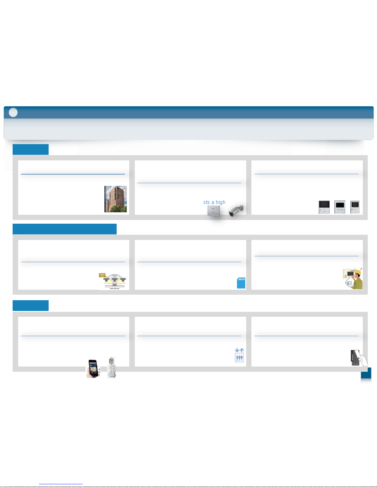
2. Role/Features/Installation
2-1. Video Intercom for Apartment Complexes
System Overview
2-2. Lobby Station (VL-V900)
Role of the VL-V900
Features of VL-V900
Installing the VL-V900
2-3. Control Box (VL-V700)
Role of the VL-V700
Features of VL-V700
2-4. Distribution Box & Repeater (VL-V701)
Role of the VL-V701
Role as a distribution mode or a repeater mode
2-5. Lift Controller (VL-V702)
Role of the VL-V702
Supported control methods of VL-V702
2-6. Extension Box (VL-V702)
Role of the VL-V703
2-7. Room Unit (Main Monitor) (VL-MVN511)
2-8. Room Unit (Main Monitor) (VL-MW251)
2-9. Room Unit (Main Monitor) (VL-MV26)
2-10. Room Unit (Main Monitor) Lineup
2-11. Room Unit Comparison chart
2-12. Apartment mode or Housing mode
INDEX
3. Wiring
3-1. Basic System Example
3-2. Basic System Configuration
3-3. Large System Example
3-4. Large System Configuration
3-5. Cable Information
3-6. Wiring type and length
3-7. Distance / How to use Repeater
3-8. Distribution Box switch settings
3-9. Lift Controller: VL-V702
3-10. Lift Controller settings (Relay control)
3-11. Lift Controller Configuration (Relay control)
3-12. Lift Controller / How to set DIP switch (relay control)
3-13. Lift Controller Configuration (Binary control)
4. Integration
4-1. PBX & Terminal (Example of configration)
4-2. Analog Security camera & Monitor
4-3. System condition and Limitations
4-4. Access Control & E-locks
4-5. Recording by SD-Card
. . . . . . . . . . . . . . . . . . . . . . . . P 4
. . . P 6
. . . . . . . . . . . . . . . . . . . . . . . P 6
. . . . . . . . . . . . . . . . . P 8
. . . . . . . . . . . . . . . . . . . . . P 8
. . . . . . . . . . . . . . . . P 9
. . . . . . . . . . . . . . . . . . . P10
. . . . . . . . . . . . . . . . . . . P12
. . . . . . . . . . . . . . . . . . . . . P12
. . . . . . . . . . . . . . . P13
. . . . . . . . . . . . . . . . P14
. . . . . . . . . . . . . . . . . . . . P14
. . . . . . . . . . . . . . . . P15
. . . . . . . . . . . . . . . . . P16
. . . . . . . . . . . . . . . . . . . P16
. . . . . . . . P17
. . . . . P19
. . . . . . P19
. . . . . . . P20
. . . . . . . . . . P21
. . . . . . . . . . . . P22
. . . . . . . . P23
. . . . . . . . P24
. . . . . . . . P25
. . . . . . . . . . . . . . . . . . . . . . . P26
. . . . . . . . . . . . . . . . . . . P27
. . . . . . . . . . . . . . . . . . . . . . . P28
. . . . . . . . . . . . . . . . . . P30
. . . . . . . . . . . . . . . . . . . . . . . . . . . P31
. . . . . . . . . . . . . . . . . . . . . . . . P32
. . . . . . . . . . . . . . . . P33
. . . . . . . . . . . . . . . . P34
. . . . . . . . . . . . . . . . . . . . . . . P35
. . . . . . . . . . . P36
. . . . . . . P37
P38
. . . . . . P42
. . . . . . . . . . . . . . . . . . . . . . . . . . . . P43
. . . . . . . . . . . . . P47
. . . . . . . . . . . . . . P49
. . . . . . . . . . . . . . . . . . . . . P50
. . . . . . . . . . . . . . . . . . . . . . . P53
5. Setup tool
5-1. Version Up by SD card
5-2. Programing
5-2-1. How to Setup
5-3. Setup tool overview
Setup tool (Create new configuration file )
Setup tool (Existing configuration file )
Setup tool ( Download the data )
5-4. Control Box – Room settings
5-5. Control Box – General settings
5-6. Lobby Station 1-3 -Room settings
5-7. Lobby Station 1-3 -General settings
5-8. Lobby station programing
5-9. Telephone programming
5-10. Main monitor programming
5-11. Restarting a device
6. Operation
6-1. Lobby station operations
6-2. Facility staff operations
. . . . . . . . . . . . . . P54
. . . . . . . . . . . . . . . . . . . . . . P55
. . . . . . . . . . . . . . . . P60
. . . . . . . P61
. . . . . . . . P62
. . . . . . . . . . P63
. . . . . . . . . . . . . P64
. . . . . . . P65
. . . . P66
. . . P67
. . . . . . . . . . . P68
. . . . . . . . . . . . P69
. . . . . . . . . P70
. . . . . . . . . . . . . . . . P71
. . . . . . . . . . . P74
. . . . . . . . . . . . . P75
INDEX
10 Appendix
10-1. VL-V900 Series (Specifications)
10-2. Installing the Power Supply Unit (VL-PS240)
10-3. Expanded system example
10-4. System Diagram of the Apartment System
. . . . . . . . . . .. P76
. P79
. . . . . . . . . . P81
7. Replace
7-1. Replace from Cat-5e Cable (IP System)
7-2. Replace from Cat-5e Cable (IP system/PoE-Switch)
7-3. Replace from Cat-3(4wire cable) system
9. FAQ
Under Construction
8. Estimate
How to make an estimate of the system ?
Question for new project and replace project
Question for replace project
. . . . . . . . . . P54
. . . . . . . .. P99
. . . . . . . . . . . . . . . . P100
. . . . . . . . . P101
. . . . . . . . . . . P109
. . . . . . . . . . . . P69
. . . . . . . . . P107

Why Choose a Panasonic
Video Intercom System?
1
4
Why Panasonic?
1
1-1. Why Panasonic Video Intercom for Apartment Complexes
Benefit
Differentiation from Competitors
Features
Large Apartment Systems
Capable of handling large apartment
buildings of up to 560 households.
Monitor Choices
Monitors can be chosen from among 3
types to suite customer needs. An exclusive
wireless monitor handset or a smartphone
can also be connected, making it is possible
to answer anywhere.
Proposed System Solutions
with the Panasonic
PBX system and security cameras
Provides communication between multiple
buildings through linked functionality with
our PBX system, which boasts a high
market share in Asia.
170 Degree Ultra Wide Angle Camera
(The industry’s largest)
This wide angle camera allows broad
lobby areas to be securely monitored.
Linked Functionality with Security
Cameras and SD Recording Functions
In addition to providing linked functionality
with security cameras, up to 90,000
images of visitors can be recorded on an
SD card.
Easy Installation and configuration
Easy and low-cost installation with 2-wire
cables. The use of PC setup tools also
shortens and simplifies configuration.
Responding to Visitors Anywhere
Throughout the Home
The door can be answered and unlocked
from anywhere in the home through the
use of a wireless monitor handset or
smartphone.
Linked Functionality
with Lift Controller
Improves convenience for visitors, and
reduces the labour cost of reception staff.
Linked Functionality
with Access Control
Linked functionality with access control
and the use of a shared residential ID
(lobby station PIN code) enables smooth
entry.

Role/ Features / Installation
1
2

System Overview
Control Box
VL-V700
Lobby Station
VL-V900
Distribution Box
VL-V701
2-1. Video Intercom for Apartment Complexes
Other Connectable Devices
Main Monitor
VL-MVN511/MW251/MV26
Role/ Features / Installation
Lift Controller
VL-V702
2
Electric Locks
PBX
Terminals
Security Camera
TV Monitor
1 unit
1 unit
4 units
Up to 1 per lobby station (up to 3 lobby stations)
1 unit
Control Box
Distribution Box
Lobby Station
Main Monitor
1 unit
28 units
3 units (w/o Extension Box)
18units (with Extension Box)
560 units
Total System
6
Extension Box
VL-V703
Entrance
7
2
Role/ Features / Installation
2-1. Video Intercom for Apartment Complexes
Guard (Security)
System
Room
Entrance
Control Box
VL-V700
Lobby Station
VL-V900
Lift Controller
VL-V702
Main Monitor
VL-MVN511/MW251/
MV26
Distribution Box
VL-V701
Monitor Lobby Station or Security Camera
Open E-Lock & Control Lift
Call & Talk
Save Images &
Logs
Security
Camera
E-LOCK
LIFT
SD
PBX
Monitor
Press
10key
Up to 3 units
Up to 560
room units total
Terminal
E-LOCK
Extension Box
VL-V703
Lobby
Station
Extend
Up to 18
Lobby Station
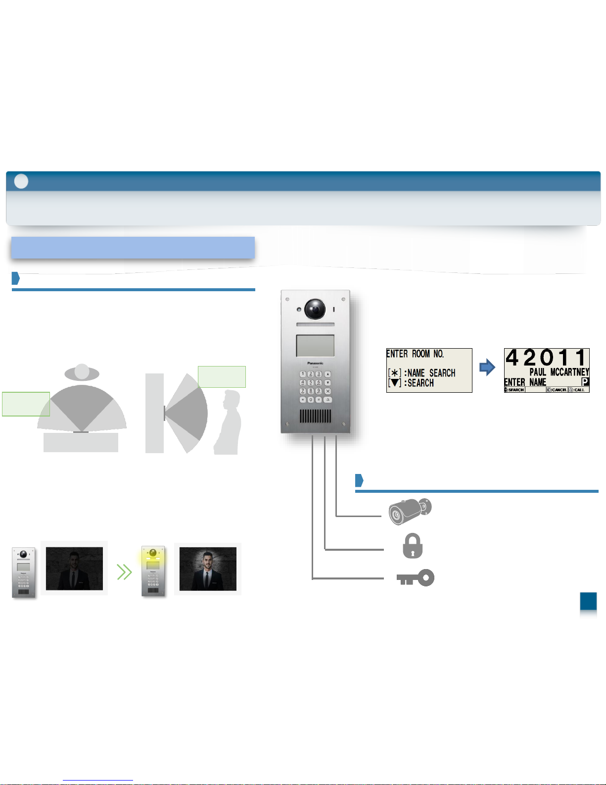
2-2. Lobby Station : VL-V900
Role of the VL-V900
Features
-4.3 inch monochrome display (white backlit LCD)
-Each resident name is registered and displayed
‐Room number can resistors up to 5 digits
-Resident Name can resistors up to 20 characters
Connectable devices
Doorphone for the public entrance of housing complexes
Destination display, calling, conversation, and electric lock
2
Role/ Features / Installation
8
Security Camera:
Panasonic Analogue Camera
Access Control:
Interface: 2Wire,
Non-Polarized
E-Lock 1:
Interface: Dry Contact
-Wide angle camera (Horizontally:170˚, vertically:115˚)
Industry
average
Approx. 90
Almost the full width is visible.
Approx.
170
Industry
average
Approx.
70
Approx.
115
The face can be seen regardless of
height and posture.
Upper/lower angle (Vertically)
Left/right angle (Horizontally)
comparison image
Equipped with White LED light
VL-V900(1.0M pixel) White LED lights
--White coloured LED lights for night color vision
The wide image taken with the wide-angle lens enables
easy, complete confirmation.
- IP55, Compliant with IK07 / -10℃to +55℃
-Blue LED backlit buttons
(Buttons that light up with a heat sensor)
Door Station is equipped with LED lights (illumination lamp).
It enables the colour display of visitors at a distance of about 50 cm at night.
9
2-2. Lobby Station : VL-V900 (Features)
2
Role/ Features / Installation
-You can program the default camera view
( Wide or 9 Zoom position) by using Setup Tool.
Wide View
Features View Angles Wide Zoom and Pan Tilt
Zoom View(Select 9 position)
- Change camera view Wide Zoom and Pan Tilt
- Change the view by MENU
‐ Select Zoom view of 9 position by
Position Guide
01
02
03
04
05
06
07
08
09
10
2
Role/ Features / Installation
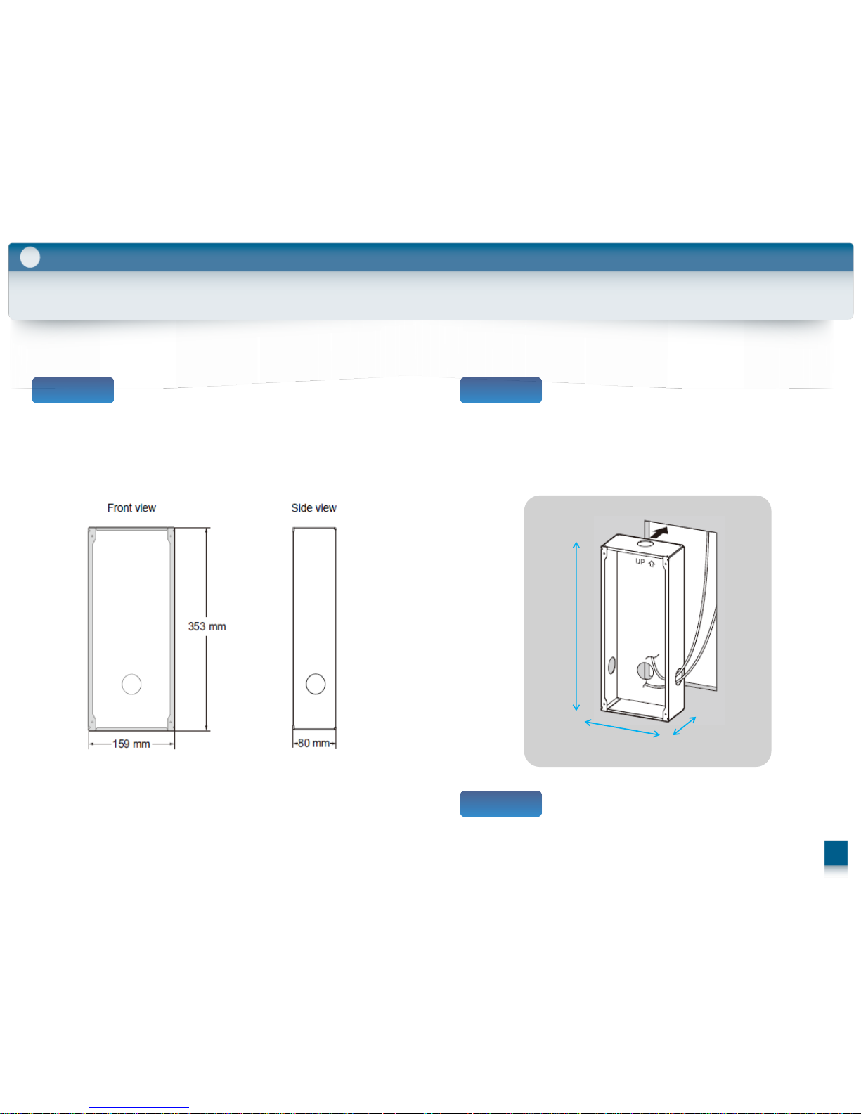
Make a hole in the wall for the flush mount box.
Step 1
159 mm
353
mm
80 mm
Open the knockout holes of the flush mount box,
and then pass all necessary cables and wires
(DC cable, wires for control box, access controller,
electric lock, etc.) through the knockout holes.
Step 2
Step 3
Mount the box in the wall.
( Note the drilling dimensions of the wall surface of the
flush mount box.)
2-2. Lobby Station : VL-V900 (Installing the Lobby Station)
2
Role/ Features / Installation
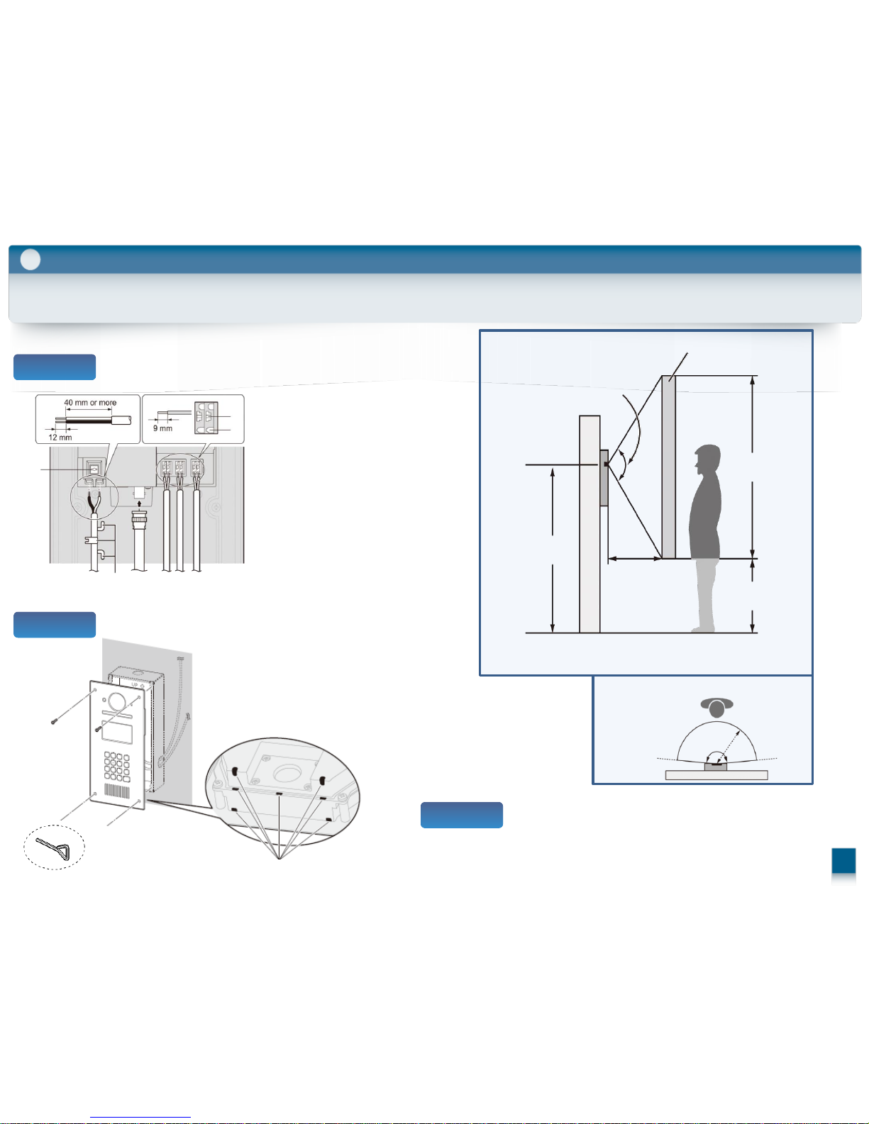
Step 4
Connect the wires and cables to the lobby station.
Attach the lobby station to the flush mount box.
Secure the lobby station to the flush mount
box with 4 screws using the hex wrench.
Step 6
(1) Cable release button for DC power
supply cable
(2) DC cable from power supply unit
(3) Hooks for securing the DC cable
(4) Coaxial cable from external camera
(5) Wires from control box
(6) Wires from access controller
(7) Wires from electric lock
(8) Wire release button
(9) Connection terminal
(1)
(2) (3) (4) (5) (6) (7)
(8)
(9)
Image range
Approx.
115°
1,500 mm
700 mm
1,600 mm
2,300 mm
500 mm
Centre of
the camera
lens
Side view
Step 5
2-2. Lobby Station : VL-V900 (Installing the Lobby Station)
Approx.
170°
Approx.
500 mm
Top view
7
11
Hex wench
Water drain holes
Distribution Box
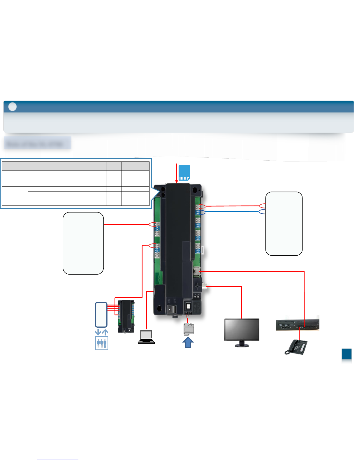
2-3. Control Box : VL-V700
2
Role/ Features / Installation
AC
Control Box
V1
V2
A1
A2
Monitor
PBX
Terminal
Lift control Box
Lift Control
System
USB
PC
Insert Here
SD card
Lobby Station
Category Meaning
POWER
(GREEN
ACCESS
(RED)
Idle Lit Off
Call or monitoring in progress Lit Lit
Accessing SD card Lit Flashing quickly
System setup PC programming in progress Lit Lit
PC connection check in progress Lit Lit
Error
Duplicate distribution box number found Off Flashing slowly
Duplicate lift controller number found Off Flashing slowly
Normal
operation
Role of the VL-V700
12
Role of the VL-V700
Features
-PBX
-PC (for program settings)
-Monitor (for real time monitoring)
13
2-3. Control Box : VL-V700
2
Role/ Features / Installation
Device for controlling the entire system
- Easy setup by Setup tool soft ware(room no. registration)
- Easy connection check by Setup tool
(Check the connections between the lobby station
and main monitor of each room)
- SD card recording (record up to 90,000 images) …...…….... (6)
& System log (date, time, action, more than 90,000events)
- Real time monitoring …………………………………………..……..….. (9)
- Operation Environment : -10℃ to 50℃
Connectable devices
….. (8)
….. (5)
….. (9)
Category Meaning
POWER
(GREEN
ACCESS
(RED)
Idle Lit Off
Call or monitoring in progress Lit Lit
Accessing SD card Lit Flashing quickly
System setup PC programming in progress Lit Lit
PC connection check in progress Lit Lit
Error
Duplicate distribution box number found Off Flashing slowly
Duplicate lift controller number found Off Flashing slowly
Normal
operation
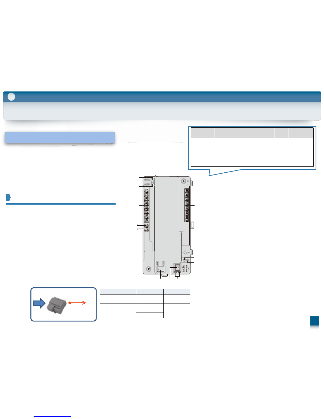
(1) Power indicator (POWER)
(2) Access indicator (ACCESS)
(3) Connection terminals for lobby stations
(4) Connection terminals for lift controllers
(5) USB port (underneath dust cover)
Used for PC programming.
(6) SD card slot
Used to save the system log.
(7) Connection terminals for distribution boxes
(8) RJ11 jack for connection to PBX
(9) Coaxial connector for external video monitor
(10) Reset button ( ・ )
Used when restarting the control box.
(11) Function button (・・)
For internal use only.
(12) Power switch
(13) Cable release button for DC power supply
cable
(14) Connection terminals for DC power supply
(1)
(2)
(3)
(4)
(5)
(6)
(7)
(8)
(9)
(10)
(11)
(12) (13) (14)
Wiring run Wire diameter Max. length
Power
supply unit
⇔
Control box
2 mm (12 AWG
)
approx. 20 m
Power
supply unit
⇔
AC power source
1.2 mm (17 AWG)
No requirement
2 mm (12 AWG)
AC
DC:24V
(14
)
Attached Power Supply Unit
(Indoor use only)
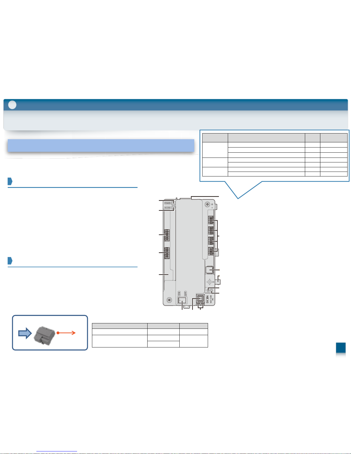
2-4. Distribution Box & Repeater : VL-V701
2
Role/ Features / Installation
AC
Distribution Box
Room unit (up to 20)
Main Monitor Door Station
#19
MVN511
MW251
#20
DB1
DB2
MV26
Termination:ON
Repeater:OFF
Control Box
Lobby Station
Category Meaning
POWER
(GREEN)
ACCESS
(RED)
Normal operation Idle Lit Off
Call or monitoring in progress Lit Lit
Error
DIP switch 8 is in the "on" position Off Flashing slowly
Two or more DIP switches are in
the "on" position
Off Flashing slowly
Role of the VL-V701
14
Role of the VL-V701
Role as a distribution mode
A repeater box is for amplifying the signal
when the control box and main monitor are
far away from each other.
Only one can be connected between
the control box and each distribution branch.
15
2-4. Distribution Box & Repeater : VL-V701
2
Functions as a distribution box or repeater.
The function can be switched ON/OFF with the Repeater switch.
Operation Environment : -10℃ to 50℃
A distribution box for connecting the control box
with the main monitor of each room. (up to 20 monitors)
Up to 7 can be connected between the control box
and the main monitors.
Role as a repeater mode
ON
REPEATER TERMINATION
As a Distribution Box (#1 to )
REPEATER TERMINATION
As a Distribution Box (#farthest only)
REPEATER TERMINATION
As a Repeater Box
Switch Setting
⑦ Dip switch
#1
⑧ Terminal Switch ⑨ Repeater switch
#2 #7
・・・
AC
DC:24V
(14
)
Attached Power Supply Unit
Role/ Features / Installation
Category Meaning
POWER
(GREEN)
ACCESS
(RED)
Normal operation Idle Lit Off
Call or monitoring in progress Lit Lit
Error
DIP switch 8 is in the "on" position Off Flashing slowly
Two or more DIP switches are in
the "on" position
Off Flashing slowly
(1) Power indicator (POWER)
(2) Access indicator (ACCESS)
(3) Connection terminals for main monitors
(4) Connection terminals (input)
for control box or distribution box
(5) DIP switches
(6) Connection terminals for main monitors
(7) Connection terminals (output)
for distribution box
(8) Terminate switch
(9) Repeater switch
(10) Reset button ( ・)
Used when restarting the distribution box.
(11) Function button (・・)
For internal use only.
(12) Power switch
(13) Cable release button for DC power supply
cable
(14) Connection terminals for DC power supply
(1)
(2)
(3)
(4)
(5)
(6)
(7)
(8)
(9)
(10)
(11)
(12) (13) (14)
Wiring run Wire diameter Max. length
Power supply unit
⇔
Distribution box
2 mm (12 AWG)
approx. 20 m
Power supply unit
⇔
AC power source
1.2 mm (17 AWG)
No requirement
2 mm (12 AWG)
(Indoor use only)
ON ON ONON ON
( on ) ( on )( on )( off )( off ) ( off )
16
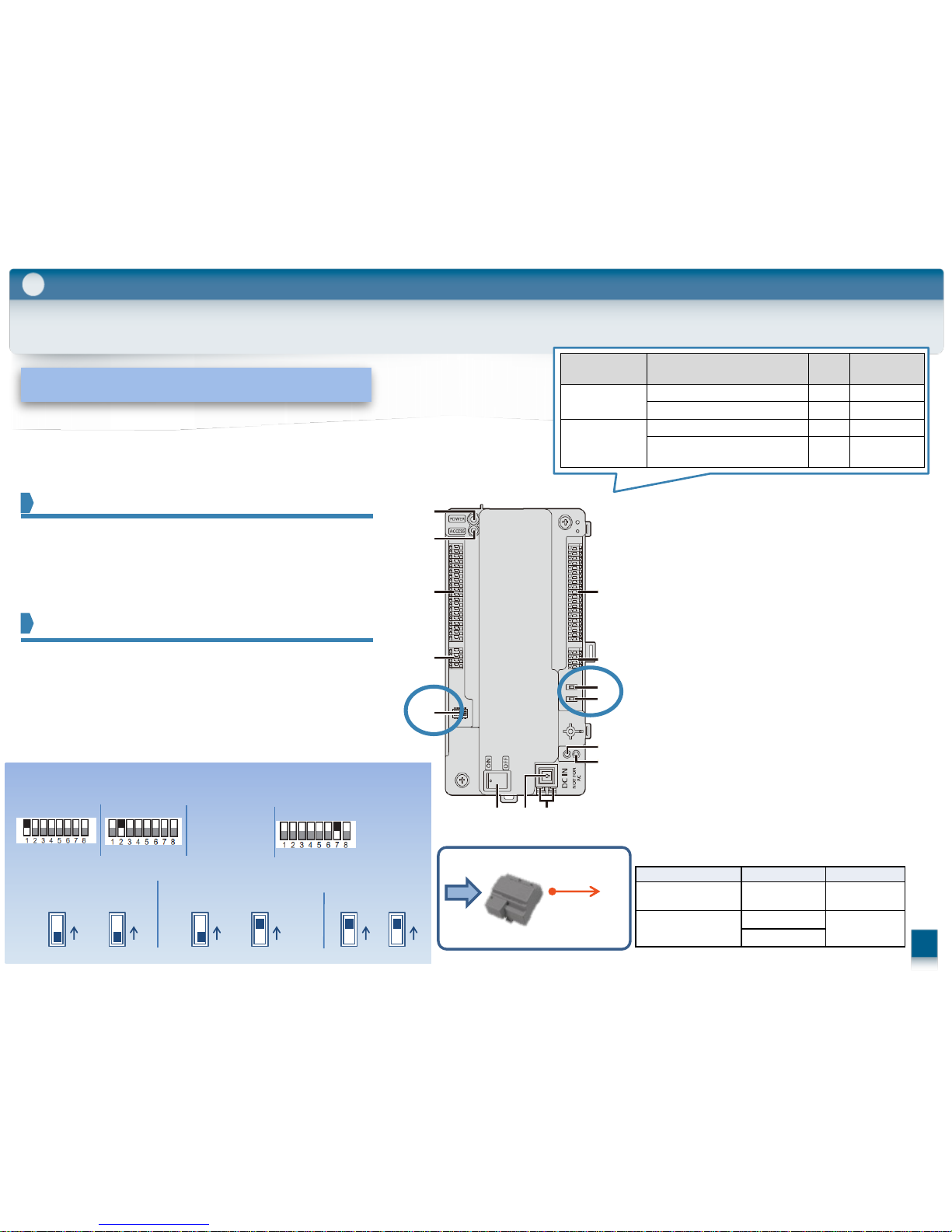
2-5. Lift Controller : VL-V702
2
Role of the VL-V702
Example Function
Controlling the destination (floor) of visitors by linking with the lift and lift control box
Role/ Features / Installation
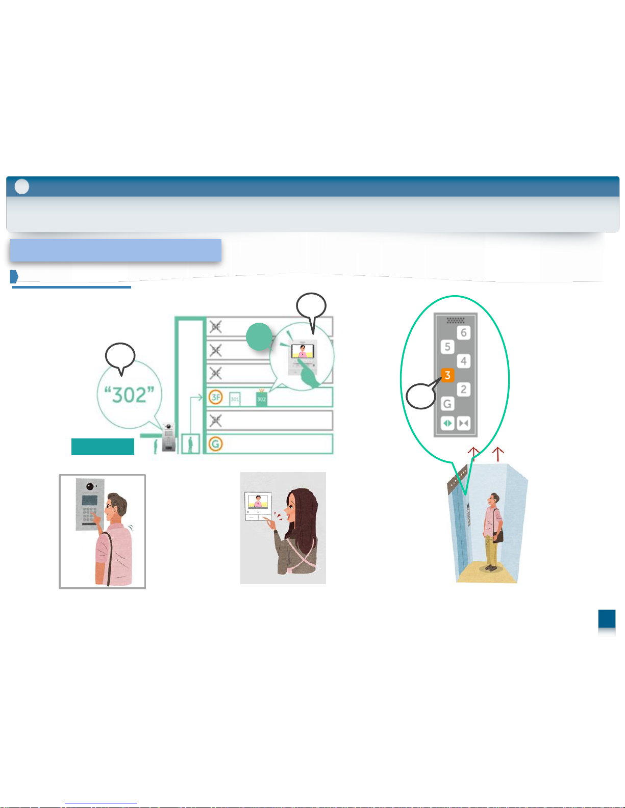
Residents 302 push the button
And answer
The Lift controller accepts
only 3rd Floor.
Visitor comes and call Room 302
For visitors
Accept
2
1
3
1. 2.
3.

2-5. Lift Controller : VL-V702
Normally Open or Close
Active time 1s-900s
2
Role/ Features / Installation
17
“302”
Accept
Door Open
Door Open
Only Relay #4(3F) will be active.
#1
(G)#2(1F)#3(2F)
#19
(18F)
#20
(19F)
Lift Control
System
Panasonic
Lift Controller
VL-V702
Lift
Control box
VL-V700
Distribution box
VL-V701
#4
(3F)
Accept
Can program the Relay operation(#1-#20)
Accept
* In order for the function to work, settings need to be confirmed in advance with the lift manufacturer.
Role of the VL-V702
Supported control methods
Controlling the destination of lifts
Controlling the destination (floor) of visitors
by linking with the lift and lift control box
Operation Environment : -10℃ to 50℃
-1:1 control (Relay Signaling) / Binary control
-Normally Open / Normally Close
-Support up to 100 Floor (up to 3 lifts)
18
2-5. Lift Controller : VL-V702
2
Role of the VL-V702
Supported control methods
Controlling the destination of lifts
Controlling the destination (floor) of visitors
by linking with the lift and lift control box
Operation Environment : -10℃ to 50℃
-1:1 control (Relay Signaling) / Binary control
-Normally Open / Normally Close
-Support up to 100 Floor (up to 3 lifts)
Role/ Features / Installation
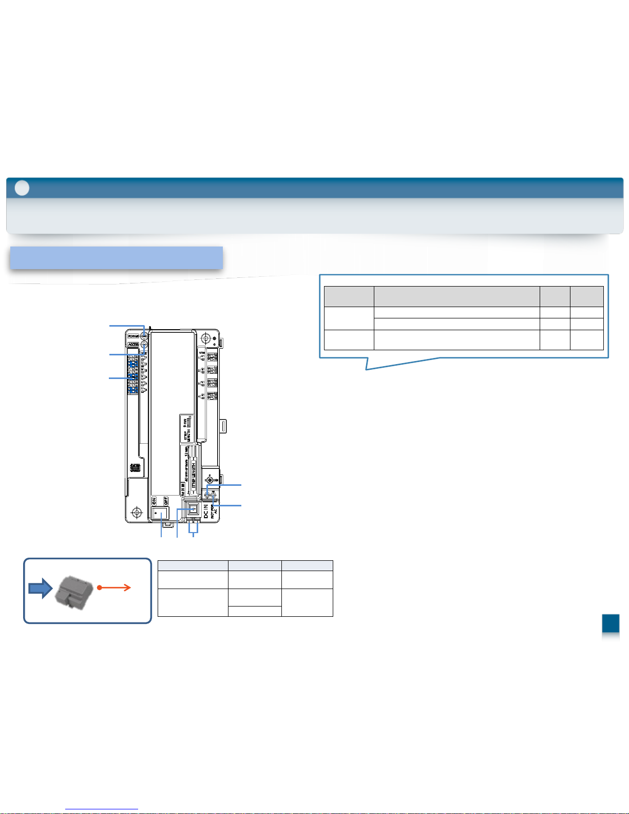
(1) Power indicator (POWER)
(2) Access indicator (ACCESS)
(3) Connection terminals for lifts
(4) Connection terminals (input)
for control box or lift controller
(5) Connection terminals (output) for lift
controller
(6) Connection terminals for lifts
(7) Reset button ( ・)
Used when restarting the lift controller.
(8) Function button (・・)
For internal use only.
(9) Power switch
(10) Cable release button for DC power supply
cable
(11) Connection terminals for DC power supply
Category Meaning
POWER
(GREEN)
ACCESS
(RED)
Idle Lit Off
Call or monitoring in progress Lit Lit
Error
DIP switch 6 or 7 is in the "on" position Off Flashing slowly
Two or more DIP switches are in the
"on" position
Off Flashing slowly
Normal
operation
(1)
(2)
(3)
(4)
(5)
(6)
(7)
(8)
(9) (10) (11)
AC
DC:24V
(11
)
Attached Power Supply Unit
Wiring run Wire diameter Max. length
Power
supply unit
⇔
Lift controller
2 mm (12 AWG)
approx. 20 m
Power
supply unit
⇔
AC power source
1.2 mm (17
AWG)
No requirement
2 mm (12 AWG)
(Indoor use only)
2-6. Extension Box : VL-V703
2
Role of the VL-V703
Extend the number of Lobby Station. ( Original 3pcs. Max. Up to 18pcs. )
Operation Environment : -10℃ to 50℃
Role/ Features / Installation
(1) Power indicator (POWER)
(2) Access indicator (ACCESS)
(3) Connection terminals for lobby station
(4) Power switch
(5) Cable release button for DC power supply cable
(6) Connection terminals for DC power supply
(7) Reset button ( ・)
Used when restarting the extension box.
(8) Function button (・・)
For internal use only.
Category Meaning
POWER
(GREEN)
ACCESS
(RED)
Idle Lit Off
Call in progress Lit Lit
Error
DIP switch 4 or 6 or 7 or 8 is in the "on" position Lit Flashing
Normal
operation
AC
DC:24V
(11
)
Attached Power Supply Unit
Wiring run Wire diameter Max. length
Power
supply unit
⇔
Lift controller
2 mm (12 AWG)
approx. 20 m
Power
supply unit
⇔
AC power source
1.2 mm (17
AWG)
No requirement
2 mm (12 AWG)
(Indoor use only)
(1)
(2)
(3)
(4) (5) (6)
(7)
(8)
19
E-Lock1
Lobby Station
E-Lock2
Door Station
Main Monitor
20
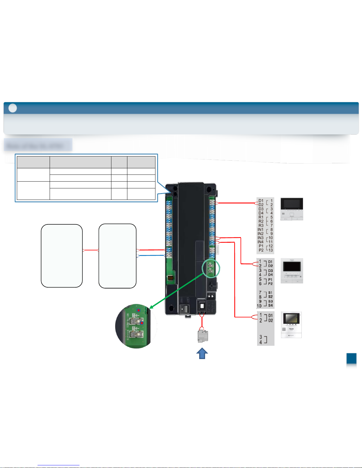
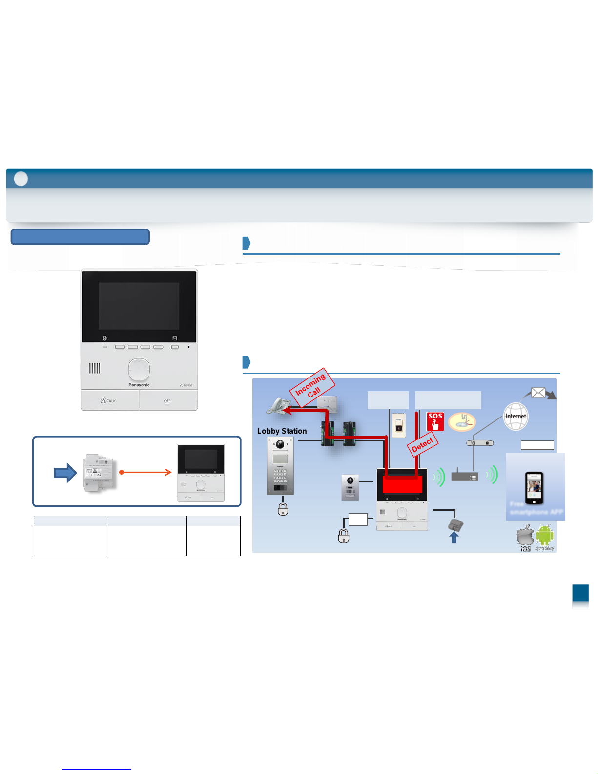
2-7. Room Unit (Main Monitor) : VL-MVN511
Easy setup, Easy installation with a Wi-Fi connection
1. Smart phone connectivity
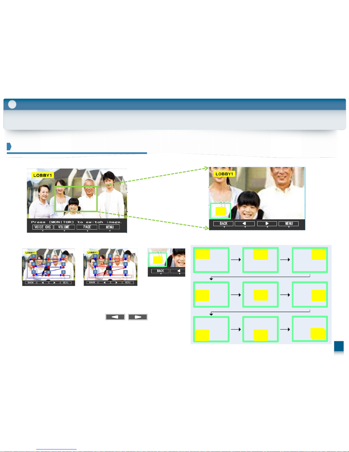
Up to 50 visitors, 8 shots per visitor can be recorded
2. Auto picture recording function
notification to smartphone by e-mail and the terminal via PBX system
3. Sensor Input, loud warning sound & notification
Sales Point
Configuration of connected devices
Role/ Features / Installation
Relay
box
*
2
*2Relay box is included with VL-SVN511,
but not included with VL-MVN511
*1Door Bell is connectable instead of a Door Station
AC
DC:24V
Attached Power Supply Unit
Wiring run Wire diameter Max. length
Power
supply unit
⇔
AC power source
Φ
1.2 mm – Φ2.0 mm
17 AWG – 12 AWG)
No requirement
2
Up to 4
Expandable
options
Free
smartphone APP
Sensor /
Door Bell
APARTMENT MODE / HOUSE MODE
*
1
*
1
AC
Power
Supply Unit
Sensor or Button
(Emergency call)
PBX
Terminal
Emergency
call
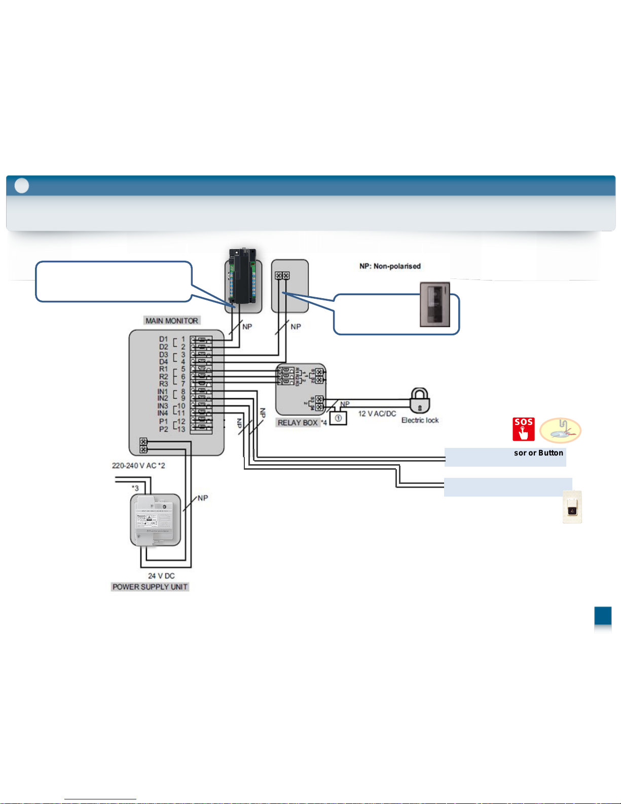
2-7. Room Unit (Main Monitor) : VL-MVN511 Rea Side
Role/ Features / Installation
2
Commercially Sensor or Button
(Support Emergency call)
Commercially Sensor or Button
(Support Door Bell)
D3,D4 :
Door Station
D1,D2 :
Distribution Box(VL-V701)
21
22
2-8. Room Unit (Main Monitor) : VL-MW251
Answer visitors anywhere at home.
Support additional sub monitors up to 4.
1. Wireless Sub Monitor
8 pictures / 1 session, max 50 sessions
Auto picture recording
2. Picture recording function
Can view visitors in color even at night
3. LED Lighting Door station
Sales Point
Configuration of connected devices
ELock1
Lobby Station
Expandable
options
E-Lock2
Main
Monitor
Door Station
VL-MW251 is connected to AC power directly.
Role/ Features / Installation
2
APARTMENT MODE / HOUSE MODE
23
2-11. Room Unit (Main Monitor) : VL-MV26
3.5 inch color LCD provides a clear image.
On screen UI helps the user to easily use.
1. Colour LCD monitor
1 pictures / 1 session, max 30 sessions
Auto picture recording
2. Picture recording function
Simple UI with big talk/off button
3. Easy to use big button
Sales Point
ELock1
Lobby Station
Main Monitor
Door Bell
Role/ Features / Installation
AC
DC:24V
Attached Power Supply Unit
Configuration of connected devices
2
Wiring run Wire diameter Max. length
Power
supply unit
⇔
AC power source
Φ
1.2 mm – Φ2.0 mm
17 AWG – 12 AWG)
No requirement
Power supply unit
⇔ Main Monitor
APARTMENT MODE
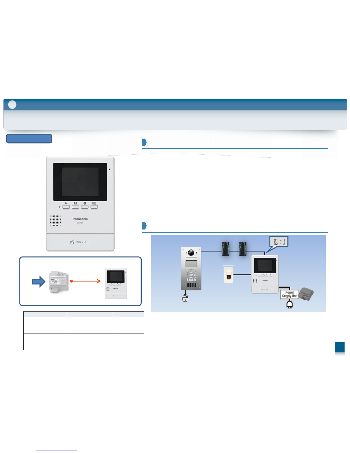
VL-V900 - VL-MVN511 series VL-V900 - VL-MW251 series VL-V900 - VL-MV26 series
Display
5-inch, wide colour 5 inch, wide colour 3.5-inch, colour
Picture recording
Yes
Up to 50 visitors, 8 shots per visitor
Yes
Up to 50 visitors, 8 shots per visitor
Yes
Up to 30
visitors, 1 shot per visitor
Door Station
Yes(Option) Yes(Option) -
Door Bell
Yes(Option: 3rdparty) - Yes(Option: 3rdparty)
E-Lock Release
Public / Individual
Yes(Option) / Yes Yes/ Yes Yes / -
Emergency
Call
Yes - -
Others
Smartphone connect (Up to 4)
E-mail notification (Up to 4)
Wireless monitor (Up to 4) -
24
2-10. Room Unit (Main Monitor) Lineup
Free App
Role/ Features / Installation
option
option
2
‘2016 release
Model
Hold
position
Image(Mode select)
Image(Apartment mode setting
VL-MVN511
VL-MW251
VL-MV26
There is no house mode
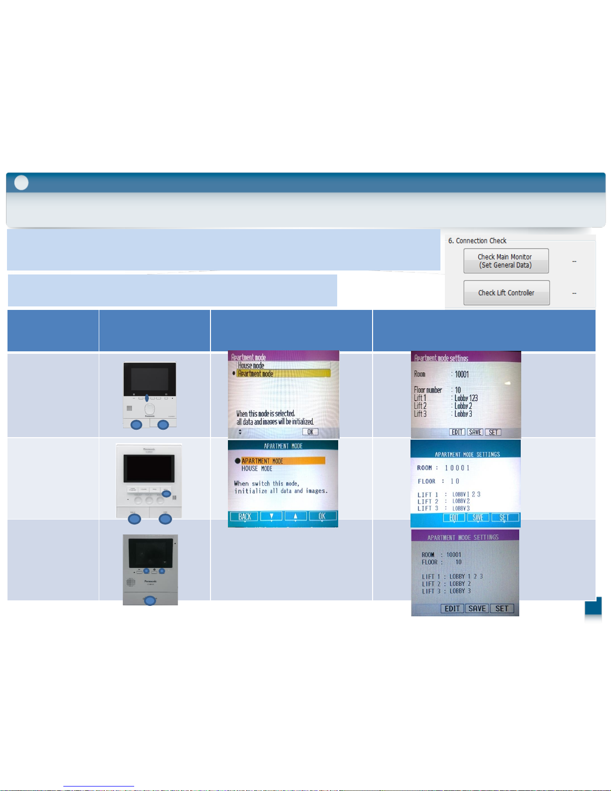
2-12. How to select the Apartment mode or Housing mode
Role/ Features / Installation
2
Default is the House mode.
But no need to change the mode. When connect to the large apartment system
and run the “Connection Check” by Setup tool, it automatically changes to Apartment mode.
Image of Setup tool
Confirmation of mode:
Just as keep hold three kind of button, and turn on the power.
25

Wiring
3
Room Units (up to 20)
3-1. Basic System Example
AC AC
AC
3
Wiring
AC AC AC AC AC AC AC AC AC
AC AC AC AC AC AC AC AC AC AC
AC
Room
System
Main Monitor
Lobby Station
Control Box
Distribution Box
Main Monitor
1 unit
1 unit
1 units
20 units
Lobby Station
VL-V900
Entrance
Control
Box
VL-V700
Distribution
VL-V701
Main Monitor
AC
26
AC
AC AC
2wire 2wire x 2 2wire
3-2. Basic System Configuration(Rear Side)
3
Wiring
Basic system example
Power Supply Unit
Lobby Station (1) Control Box (1) Distribution Box (1)
Room unit (up to 20)
Main Monitor Door Station
#1
#19
Power Supply Unit
Power Supply Unit
27
MVN511
MW251
#20
DB1
DB2
MV26
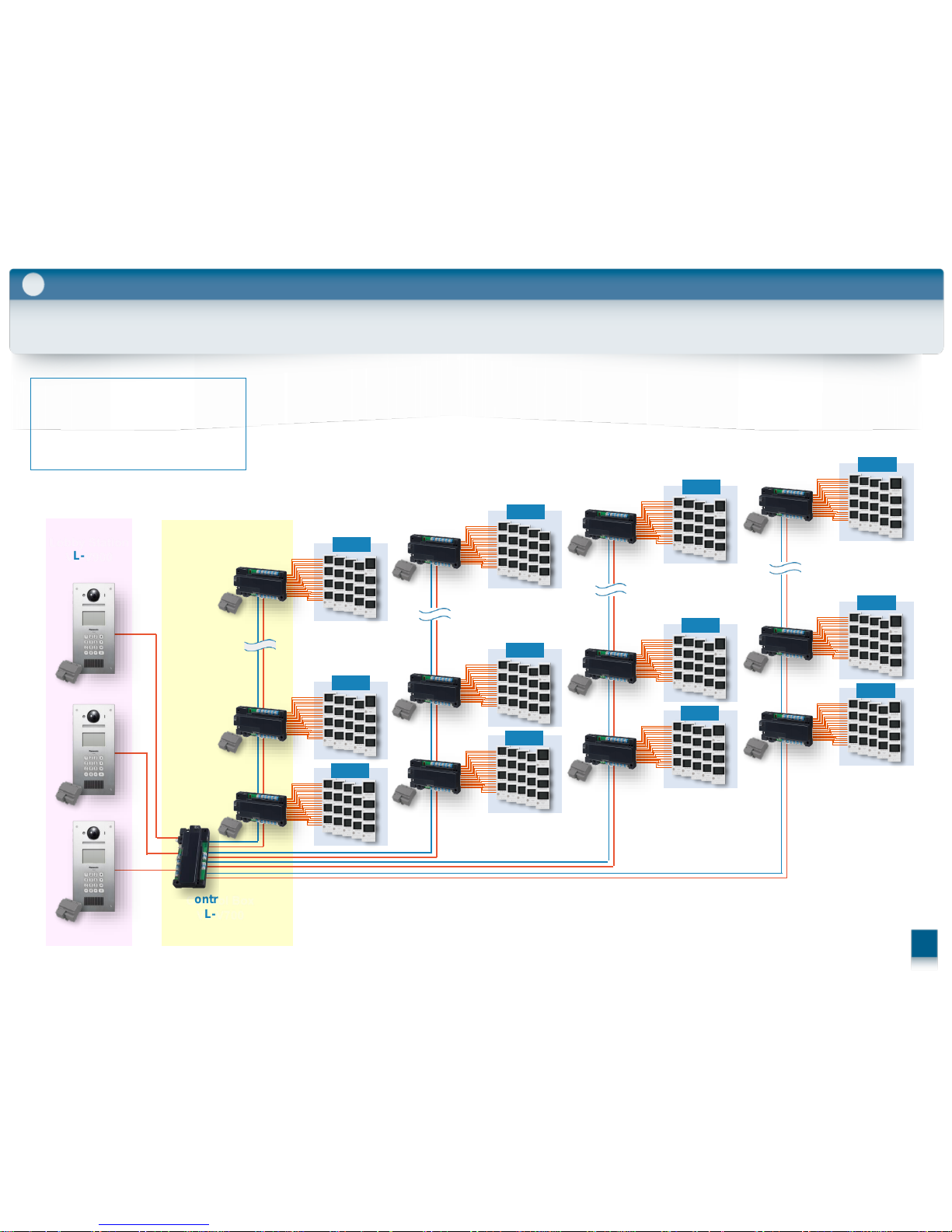
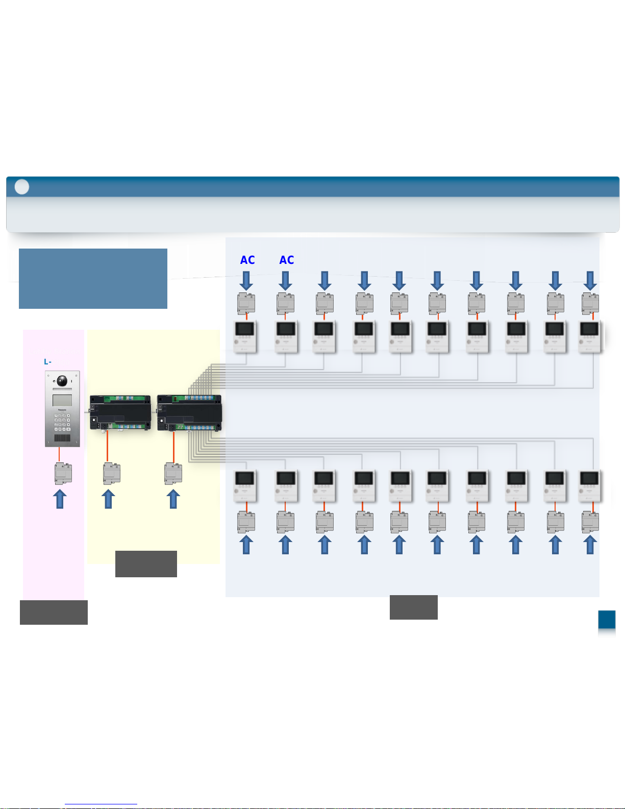
3-3. Large system example
3
Wiring
Lobby Station
VL-V900
Lobby Station
Control Box
Distribution Box
Main Monitor
3 units
1 unit
28 units
560 units
Control Box
VL-V700
4 branches x 7 series connections x 20 dividers = 560 units
1-1
1-2
1-7
2-1
2-2
2-7
3-1
3-2
3-7
4-1
4-2
4-7
Distribution
VL-V701
28
 Loading...