

Panasonic VDR-D210P, VDR-D230P, VDR-D210PC, VDR-D220PC, VDR-D230PC Service Manual
...
Digital Video Camcorder
VDR-D210P
VDR-D220P
VDR-D230P
VDR-D210PC
VDR-D220PC
VDR-D230PC
Vol. 1
ORDER NO. MKE0701450CE
B17
Colours
(S)...................Silver Type
© 2007 Panasonic Shikoku Electronics Co., Ltd. All
rights reserved. Unauthorized copying and
distribution is a violation of law.

VDR-D210P / VDR-D220P / VDR-D230P / VDR-D210PC / VDR-D220PC / VDR-D230PC
CONTENTS
Page Page
1 Safety Precautions 3
1.1. General Guidelines
2 Warning
2.1. Prevention of Electro Static Discharge (ESD) to
Electrostatically Sensitive (ES) Devices
2.2. How to Recycle the Lithium Battery
2.3. How to Replace the Lithium Battery
3 Service Navigation
3.1. Introduction
3.2. About Lead Free Solder (PbF)
4 Specifications
5 Service Mode
5.1. Error Display
5.2. Service Menu
6 Service Fixture & Tools
6.1. Service Fixture and Tools
6.2. Service Position
6.3. Removal/Installation of F.P.C. From Non ZIF (Zero
Insertion Force) Connector
6.4. Method for Ejecting the DVD Tray Manually
6.5. EEPROM Data
6.6. Special Note
6.7. Model No. Identification Mark
7 Disassembly and Assembly Instructions
7.1. Cabinet Section
8 Measurements and Adjustments
8.1. Electrical Adjustment
9 Maintenance
9.1. Cleaning Lens, Viewfinder and LCD Panel
9.2. Cleaning disc and optical pickup
10 Tr oubleshooting
11 Voltage Chart of Connectors on Main P.C.B.
3
12 Block Diagrams
4
13 Schematic Diagrams
13.1. SCHEMATIC DIAGRAM & CIRCUIT BOARD LAYOUT
4
4
5
6
6
6
7
8
8
8
10
14 Printed Circuit Board
10
11
13
14
14
15 Ex ploded View
15
15
16
16
35
35
37
16 Replacement Parts Lists
37
37
39
NOTES
13.2. FRONT SCHEMATIC DIAGRAM
13.3. BOTTOM SCHEMATIC DIAGRAM
13.4. LCD BACKLIGHT SCHEMATIC DIAGRAM
13.5. SIDE R / EVF FPC / EVF BACKLIGHT / LED LIGHT
SCHEMATIC DIAGRAMS
13.6. CCD / REAR CASE / LCD SW SCHEMATIC DIAGRAMS
13.7. SIDE L/OPERATION / DISK COVER LOCK SCHEMATIC
DIAGRAMS
13.8. INTERCONNECTION SCHEMATIC DIAGRAM
14.1. FRONT P.C.B.
14.2. BOTTOM P.C.B.
14.3. LCD BACKLIGHT P.C.B.
14.4. SIDE R P.C.B.
15.1. MAIN PARTS SECTION
15.2. FRONT HOOD AND FRONT P.C.B. SECTION
15.3. SIDE R OPERATION AND LCD SECTION
15.4. CCD AND LENS SECTION
15.5. GRIP COVER AND EVF SECTION
15.6. PACKING PARTS AND ACCESSORIES SECTION
16.1. REPLACEMENT NOTES
16.2. MECHANICAL REPLACEMENT PARTS LIST
16.3. ELECTRICAL REPLACEMENT PARTS LIST
48
49
51
51
52
53
54
55
56
57
58
59
59
60
61
62
63
63
64
65
66
67
68
69
69
70
71
2

1 Safety Precautions
1.1. General Guidelines
1. IMPORTANT SAFETY NOTICE
There are special components used in this equipment
which are important for safety. These parts are marked by
in the Schematic Diagrams, Circuit Board Layout,
Exploded Views and Replacement Parts List. It is essential
that these critical parts should be replaced with
manufacturer’s specified parts to prevent shock, fire, or
other hazards. Do not modify the original design without
permission of manufacturer.
2. An Isolation Transformer should always be used during the
servicing of AC Adaptor whose chassis is not isolated from
the AC power line. Use a transformer of adequate power
rating as this protects the technician from accidents
resulting in personal injury from electrical shocks. It will also
protect AC Adaptor from being damaged by accidental
shorting that may occur during servicing.
3. When servicing, observe the original lead dress. If a short
circuit is found, replace all parts which have been
overheated or damaged by the short circuit.
4. After servicing, see to it that all the protective devices such
as insulation barriers, insulation papers shields are properly
installed.
5. After servicing, make the following leakage current checks
to prevent the customer from being exposed to shock
hazards.
VDR-D210P / VDR-D220P / VDR-D230P / VDR-D210PC / VDR-D220PC / VDR-D230PC
3
VDR-D210P / VDR-D220P / VDR-D230P / VDR-D210PC / VDR-D220PC / VDR-D230PC
2 Warning
2.1. Prevention of Electro Static Discharge (ESD) to Electrostatically Sensitive (ES) Devices
Some semiconductor (solid state) devices can be damaged easily by static electricity. Such components commonly are called
Electrostatically Sensitive (ES) Devices. Examples of typical ES devices are integrated circuits and some field-effect transistors and
semiconductor "chip" components. The following techniques should be used to help reduce the incidence of component damage
caused by electro static discharge (ESD).
1. Immediately before handling any semiconductor component or semiconductor-equipped assembly, drain off any ESD on your
body by touching a known earth ground. Alternatively, obtain and wear a commercially available discharging ESD wrist strap,
which should be removed for potential shock reasons prior to applying power to the unit under test.
2. After removing an electrical assembly equipped with ES devices, place the assembly on a conductive surface such as
aluminum foil, to prevent electrostatic charge buildup or exposure of the assembly.
3. Use only a grounded-tip soldering iron to solder or unsolder ES devices.
4. Use only an antistatic solder removal device. Some solder removal devices not classified as "antistatic (ESD protected)" can
generate electrical charge sufficient to damage ES devices.
5. Do not use freon-propelled chemicals. These can generate electrical charges sufficient to damage ES devices.
6. Do not remove a replacement ES device from its protective package until immediately before you are ready to install it. (Most
replacement ES devices are packaged with leads electrically shorted together by conductive foam, aluminum foil or comparable
conductive material).
7. Immediately before removing the protective material from the leads of a replacement ES device, touch the protective material
to the chassis or circuit assembly into which the device will be installed.
CAUTION :
Be sure no power is applied to the chassis or circuit, and observe all other safety precautions.
8. Minimize bodily motions when handling unpackaged replacement ES devices. (Otherwise harmless motion such as the
brushing together of your clothes fabric or the lifting of your foot from a carpeted floor can generate static electricity (ESD)
sufficient to damage an ES device).
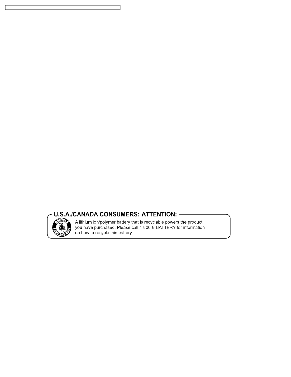
2.2. How to Recycle the Lithium Battery
4
VDR-D210P / VDR-D220P / VDR-D230P / VDR-D210PC / VDR-D220PC / VDR-D230PC
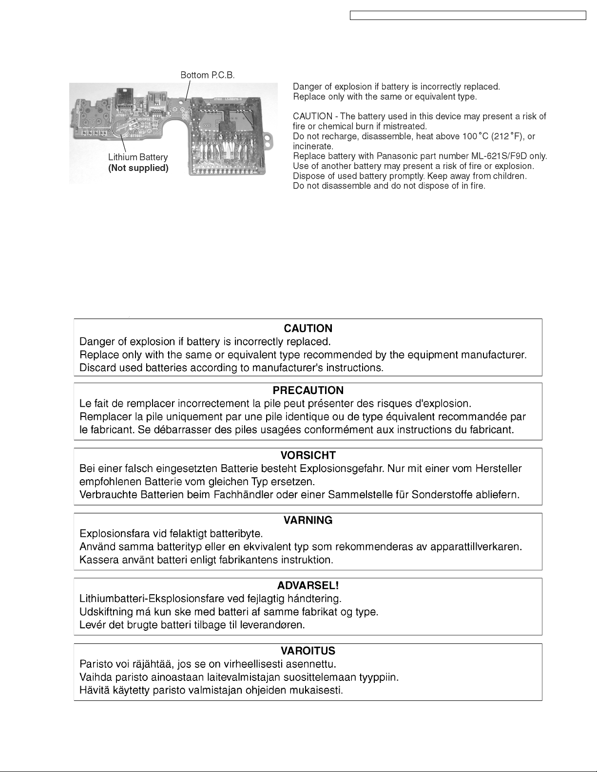
2.3. How to Replace the Lithium Battery
The lithium battery (CGR-F/202AW) is not supplied as a service part and must be replaced as part of the Bottom P.C.B. (Refer to
“Disassembly and Assembly Instructions.")
NOTE:
This Lithium battery is a critical component. (Type No.: CGR-F/202AW Manufactured by Panasonic.) (Not supplied)
It must never be subjected to excessive heat or discharge.
It must therefore only be fitted in equipment designed specifically for its use.
Replacement batteries must be of the same type and manufacture.
They must be fitted in the same manner and location as the original battery, with the correct polarity contacts observed.
Do not attempt to re-charge the old battery or re-use it for any other purpose.
It should be disposed of in waste products destined for burial rather than incineration.
5

VDR-D210P / VDR-D220P / VDR-D230P / VDR-D210PC / VDR-D220PC / VDR-D230PC
3 Service Navigation
3.1. Introduction
This service manual contains technical information which will allow service personnel´s to understand and service this model.
Please place orders using the parts list and not the drawing reference numbers.
If the circuit is changed or modified, this information will be followed by supplement service manual to be filed with original service
manual.
Note 1:
AC Adaptor used on these movie camera is PV-DAC14D. However, DE-974FB is supplied as a replacement part for PVDAC14D. This AC Adaptor is supplied only as a unit.
3.2. About Lead Free Solder (PbF)
6

4 Specifications
VDR-D210P / VDR-D220P / VDR-D230P / VDR-D210PC / VDR-D220PC / VDR-D230PC
7

VDR-D210P / VDR-D220P / VDR-D230P / VDR-D210PC / VDR-D220PC / VDR-D230PC
5 Service Mode
5.1. Error Display
"PUSH THE RESET SWITCH" is displayed automatically on the EVF or the LCD Monitor when an undesirable condition has
occurred.
Fig. 1
Note:
When "PUSH THE RESET SWITCH" is displayed repeatedly, service is required. Check the Error Code which is listed in the
Service Menu.
5.2. Service Menu
When abnormal detection contents are confirmed, do the following operation. Automatic diagnosis code will bedisplayed. (Service
Menu)
To enter the Service Menu
Push the [DELETE], [JOYSTICK CONTROL LEFT] and [RECORDING START/STOP] simultaneously for 3 seconds (with no
SD Card inserted).
Note:
If a Disc or SD Card is inserted, the above operation will not work.
Fig. 2-1
8

Note:
Only perform items 1, 3, and 4 in the Service Menu.
To select the Item
1. Set to Service Menu.
2. Press [JOYSTICK CONTROL UP/DOWN] to select item [1], [3], or [4].
3. Press [JOYSTICK CONTROL RIGHT] to display [YES/NO] screen.
4. Press [JOYSTICK CONTROL UP/DOWN] to select [YES].
5. Press [JOYSTICK CONTROL CENTER] to end.
VDR-D210P / VDR-D220P / VDR-D230P / VDR-D210PC / VDR-D220PC / VDR-D230PC
To exit the Service Menu
Unplug the AC Cord.
Fig. 2-2
9

VDR-D210P / VDR-D220P / VDR-D230P / VDR-D210PC / VDR-D220PC / VDR-D230PC
6 Service Fixture & Tools
6.1. Service Fixture and Tools
10

6.2. Service Position
VDR-D210P / VDR-D220P / VDR-D230P / VDR-D210PC / VDR-D220PC / VDR-D230PC
Laser light striking the eye may cause your eyesight
to be lost: For safety, be sure to remove any power
supply (AC adaptor/charger, battery, etc.) from the
DVD video camera/recorder before starting work.
CAUTION: VISIBLE LASER RADIATION DO NOT
STARE INTO THE BEAM OR VIEW DIRECTLY WITH
OPTICAL INSTRUMENTS CLASS 2M
Optical pickup
Caution
<CSA requirement>
6.2.1. Extension Cables for Service Position
Using the following Extension Cables, place the unit as shown for check and service.
Note :
1. The LCD open/close Switch is for changing between LCD Display or EVF Display. When turning on EVF Display, close the LCD
Shaft or place some paper or tape, etc. on LCD open/close Switch so that LCD open/close Switch stays ON.
2. To eject the DVD manually, slide the Lock lever on the Disc Cover Lock Unit for a short time or slide the EJECT switch.
3. Use a grounded ESD wrist strap while disassembling the Lens portion.
4. Connect the F.P.C.s to the connectors, verifying the direction of F.P.C.s.
The Main P.C.B. or a chip part will be damaged if the 60 Pin Extension Cable (LSUA0061) is misconnected.
5. Use extreme care when plugging in or unplugging connectors.
11

VDR-D210P / VDR-D220P / VDR-D230P / VDR-D210PC / VDR-D220PC / VDR-D230PC
Fig. 3
12
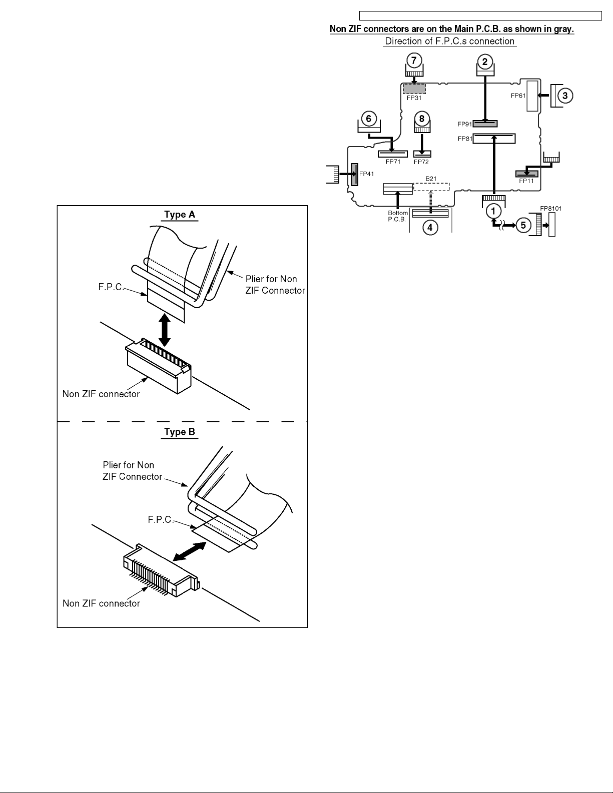
6.3. Removal/Installation of F.P.C.
From Non ZIF (Zero Insertion
Force) Connector
Removal/Installation of F.P.C. from the Non ZIF (Zero
Insertion Force) connector:
1. The Non ZIF connectors and the ZIF connectors are used
on the unit. And there are 2 types (Type A, Type B) of Non
ZIF connectors.
2. To remove the F.P.C. from the Non ZIF connector, use the
Plier for Non ZIF Connector (LSVQ0028) to pull out the
F.P.C. as shown. The same Plier for Non ZIF Connector
(LSVQ0028) should also be used to install the F.P.C. to the
Non ZIF Connector.
VDR-D210P / VDR-D220P / VDR-D230P / VDR-D210PC / VDR-D220PC / VDR-D230PC
Fig. 4-2
Fig. 4-1
3. Connect the F.P.C.s to the Non ZIF connectors, verifying
the direction of F.P.C as shown.
13
VDR-D210P / VDR-D220P / VDR-D230P / VDR-D210PC / VDR-D220PC / VDR-D230PC
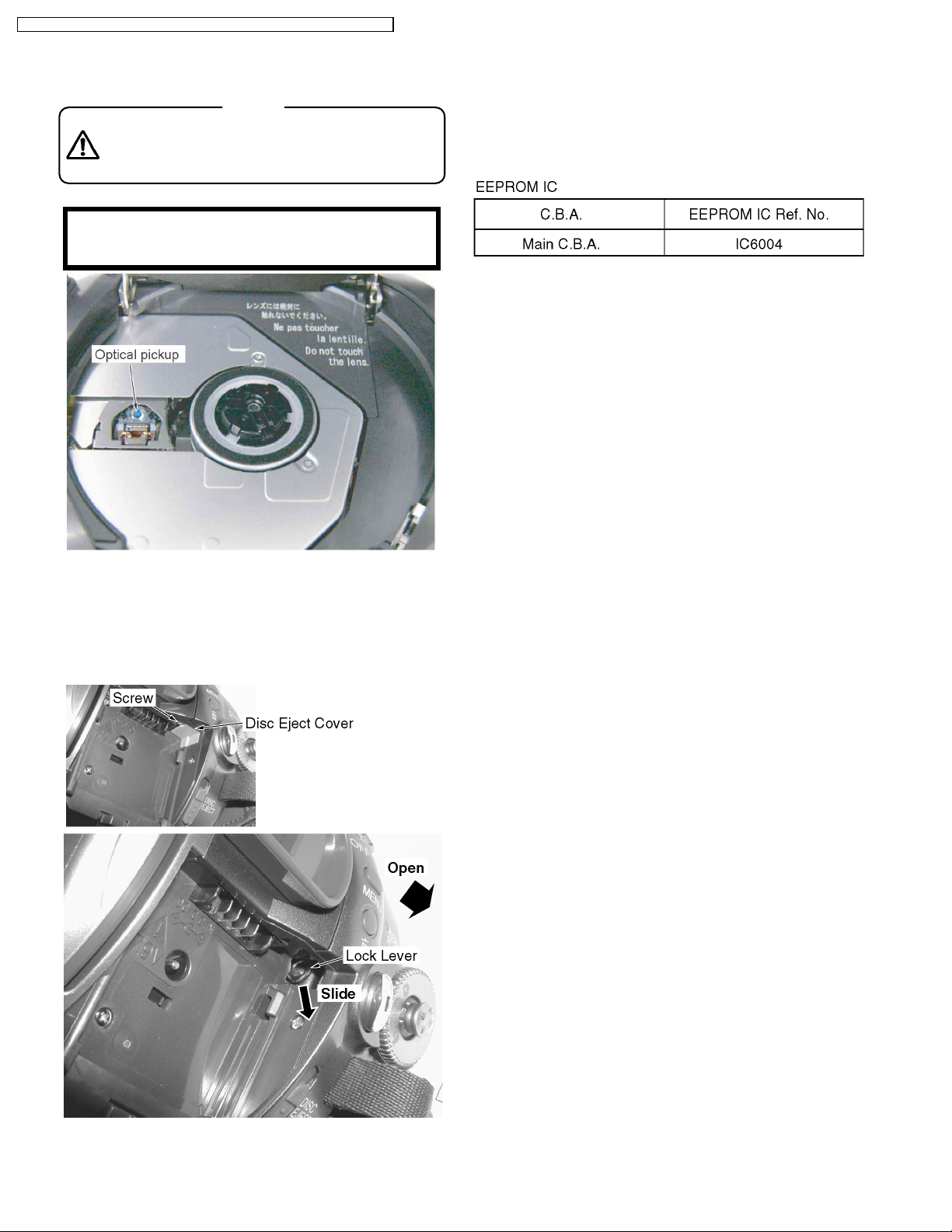
6.4. Method for Ejecting the DVD Tray Manually
Caution
Laser light striking the eye may cause your eyesight
to be lost: For safety, be sure to remove any power
supply (AC adaptor/charger, battery, etc.) from the
DVD video camera/recorder before starting work.
<CSA requirement>
CAUTION: VISIBLE LASER RADIATION DO NOT
STARE INTO THE BEAM OR VIEW DIRECTLY WITH
OPTICAL INSTRUMENTS CLASS 2M
Optical pickup
6.5. EEPROM Data
CAUTION:
Be sure to save the EEPROM data using PC-EVR
Adjustment Program before service and adjustment in
order to make sure to avoid an accidental data loss, etc.
using PC-EVR Adjustment Program by first.
Perform the following procedures;
1. Remove the Disc Eject Cover by removing the screw.
2. Slide the Lock Lever with a screwdriver, etc., to open the
Disc Cover.
3. Remove the Disc from the Tray.
Fig. 5
14

6.6. Special Note
All integrated circuits and many other semiconductor devices
are electrostatically sensitive and therefore require the special
handlings techniques described under the
"ELECTROSTATICALLY SENSITIVE (ES) DEVICES" section
of this service manual.
6.7. Model No. Identification Mark
Use Marks shown in the chart below to distinguish the different
models included in this Service Manual.
VDR-D210P / VDR-D220P / VDR-D230P / VDR-D210PC / VDR-D220PC / VDR-D230PC
15

VDR-D210P / VDR-D220P / VDR-D230P / VDR-D210PC / VDR-D220PC / VDR-D230PC
7 Disassembly and Assembly Instructions
7.1. Cabinet Section
7.1.1. DISASSEMBLY FLOWCHART
This flow chart indicates the disassembly steps of the
cabinet parts and the P.C.Boards in order to gain access to
item (s) to be serviced. When reassembling, perform the
step (s) in the reverse order. Bend, route and dress the
wires as they were originally.
Caution
Laser light striking the eye may cause your eyesight
to be lost: For safety, be sure to remove any power
supply (AC adaptor/charger, battery, etc.) from the
DVD video camera/recorder before starting work.
<CSA requirement>
CAUTION: VISIBLE LASER RADIATION DO NOT
STARE INTO THE BEAM OR VIEW DIRECTLY WITH
OPTICAL INSTRUMENTS CLASS 2M
Optical pickup
Note :
1. When removing the cabinet, work with care so as not to
break the Locking Tabs.
2. Place a cloth or some other soft material under the P.C.
Boards or Unit to prevent damage.
3. When reinstalling, ensure that the connectors are
connected and electrical components have not been
damaged.
4. Do not supply power to the unit during disassembly and
reassembly.
16
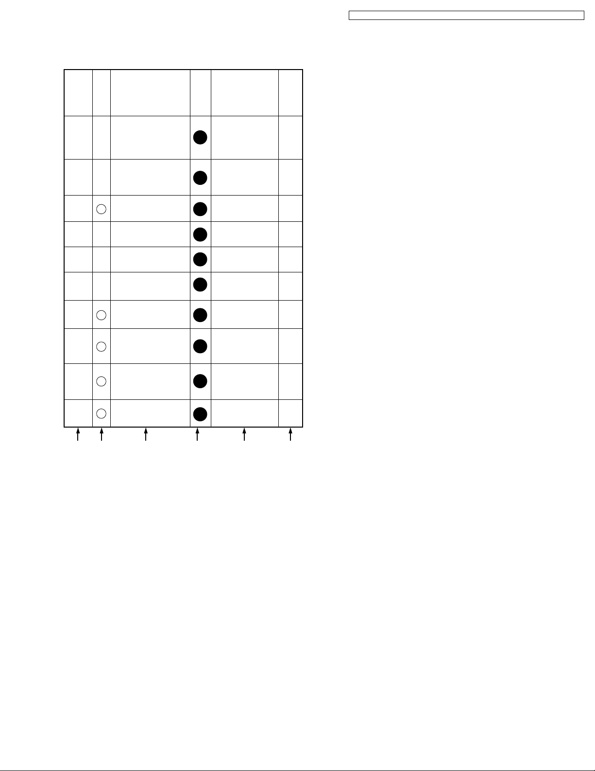
7.1.2. Disassembly Method
MAIN PARTS PORTION
STEP
No.
Ref.
No.
-
1
2
-
27
3
PART REMOVE
Front/Mic Ass'y
Side R &
LCD Ass'y
Rear Case Unit
Section
No.
1
1
1
(518), (537),
2(519), 2(533),
FP6501, Hand
Strap
2(518), 4(519),
(537), FP81,
2(L-1), (Shoe)
(537), (16)
(519), FP11
VDR-D210P / VDR-D220P / VDR-D230P / VDR-D210PC / VDR-D220PC / VDR-D230PC
NOTE
1
2
3
-
4
5 - Bottom Ass'y
6 - Lens Ass'y
7
8
9
10
Grip/EVF Ass'y
E10
Main P.C.B.
DVD Drive Frame
2
Unit
Disc Cover Lock
3
Unit
Side L Operation
1
Unit
2(519), (537),
1
FP91
3(519), B51
1
(456), FP31,
1
FP71, FP72
3(519), FP61,
1
B21
2(540), (28)
4(537), (6),
1
Connector
2(537)
1
-----
1
4
5
6
7
8
8
-
A B C D E F
How to read chart shown above:
A: Order of Procedure steps.
When reassembling, perform steps(s) in reverse order.
B: Ref No.
C: Part to be removed or installed.
D: Section No.
E: Identification of part to be removed, unhooked, unlocked,
released, unplugged, unclamped, or unsoldered.
3(404)= 3 Screws (404), 2(L-1) = 2 Looking Tabs (L-1)
F: Refer to "Notes in chart."
17
VDR-D210P / VDR-D220P / VDR-D230P / VDR-D210PC / VDR-D220PC / VDR-D230PC
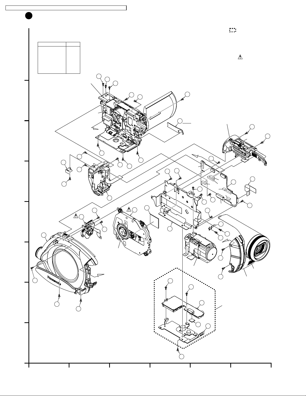
1
MAIN PARTS SECTION
COMPARISON CHART
OF MODELS & MARKS
MODEL
VDR-D210P
VDR-D210PC
H
G
VDR-D220P
VDR-D220PC
VDR-D230P
VDR-D230PC
MARK
A
B
C
D
E
F
Side R & LCD Ass'y
518
2
518
-
2
518
-
1
(L-1)
B
F
537
Note:
1. Parts with no Ref. No. in "EXPLODED VIEW" are not supplied.
And some Ref. No. will be skipped. Be sure to make your
orders of replacement parts according to the parts list.
2. The parts indicated by the dotted line are for Ass'y only
and are not supplied.
3. Disregard Ref. No. suffixes when ordering parts. They are used to
describe parts in "Disassembly and Assembly Instructions" section.
IMPORTANT SAFTY NOTICE:
COMPONENTS IDENTIFIED BY THE SIGN HAVE
SPECIAL CHARACTERISTICS IMPORTANT FOR SAFETY.
WHEN REPLACING ANY OF THESE COMPONENTS,
USE ONLY THE SPECIFIED PARTS.
519
-
10
(A,B)
2
Grip / EVF Ass'y
-
4
519
-
4
(L-1)
519
-
2
537
-
1
519
-
519
-
2
16
519
-
2
E
537
-
3
2
-
1
519
-
519
3
-
1
519
537
-
8
27
8
537
-
8
2
537
B
519
-
7
FP61
-
8
-
6
456
537
-
8
537
FP11
FP72
519
-
-
8
FP91
FP81
7
B21
FP31
B51
E10
FP71
519
11
-
7
3
D
537
-
8
6
1
28
540
-
540
8
-
8
A
Connector
533
-
533
1
FP6501
-
1
Front / Mic Ass'y
C
Lens Ass'y
A
537
-
4
519
519
B
A
519
-
5
1
-
5
519
-
519
2 3 4 5 6
706
E30
7
Bottom Ass'y
5
18

FRONT/HOOD PORTION
STEP
No.
Ref.
No.
E20
1
PART REMOVE
Front P.C.B.
Section
No.
3(537), FP6502
2
VDR-D210P / VDR-D220P / VDR-D230P / VDR-D210PC / VDR-D220PC / VDR-D230PC
NOTE
9
2
3
4
(For models with Light)
53
LED Light F.P.C.
(For models with Light)
52
LED Light Lens
51
Front/Hood Unit
2(537), (54)
2
-----
2
-----
2
2
9
9
9
A B C D E F
How to read chart shown above:
A: Order of Procedure steps.
When reassembling, perform steps(s) in reverse order.
B: Ref No.
C: Part to be removed or installed.
D: Section No.
E: Identification of part to be removed, unhooked, unlocked,
released, unplugged, unclamped, or unsoldered.
3(404)= 3 Screws (404), 2(L-1) = 2 Looking Tabs (L-1)
F: Refer to "Notes in chart."
19

VDR-D210P / VDR-D220P / VDR-D230P / VDR-D210PC / VDR-D220PC / VDR-D230PC
2
FRONT HOOD AND FRONT P.C.B. SECTION
COMPARISON CHART
OF MODELS & MARKS
MODEL
VDR-D210P
H
VDR-D210PC
VDR-D220P
VDR-D220PC
VDR-D230P
VDR-D230PC
MARK
A
B
C
D
E
F
Note:
1. Parts with no Ref. No. in "EXPLODED VIEW" are not supplied.
And some Ref. No. will be skipped. Be sure to make your
orders of replacement parts according to the parts list.
2. The parts indicated by the dotted line are for Ass'y only
and are not supplied.
3. Disregard Ref. No. suffixes when ordering parts. They are used to
describe parts in "Disassembly and Assembly Instructions" section.
G
F
E
537
537
537
FP6502
E20
(C,D,E,F)
537
51
701
705
702
D
(C,D,E,F)
537
(C,D,E,F)
54
(C,D,E,F)
C
B
A
1
2 3 4 5 6
53
(C,D,E,F)
52
20

VDR-D210P / VDR-D220P / VDR-D230P / VDR-D210PC / VDR-D220PC / VDR-D230PC
SIDE R OPERATION PORTION
STEP
No.
Ref.
No.
E60
1
PART REMOVE
Side R P.C.B.
A B C D E F
How to read chart shown above:
A: Order of Procedure steps.
When reassembling, perform steps(s) in reverse order.
B: Ref No.
C: Part to be removed or installed.
D: Section No.
E: Identification of part to be removed, unhooked, unlocked,
released, unplugged, unclamped, or unsoldered.
3(404)= 3 Screws (404), 2(L-1) = 2 Looking Tabs (L-1)
F: Refer to "Notes in chart."
Section
No.
2(537), P6301
3
NOTE
10
LCD PORTION
STEP
No.
Ref.
No.
5
1
33
2
44
3
E40
4
34
5
-
6
35
PART REMOVE
LCD Protector
LCD Case A Unit
LCD Case B Unit
LCD Backlight
P.C.B.
LCD Case B
LCD Panel Ass'y
LCD Shield Case
A B C D E F
Section
No.
(533)
3
2(519), 8(L-1)
3
FP8101
3
(533), 3(L-3),
3
FP8102
3(L-2)
3
3(L-4)
3
NOTE
11
11
11
12
12
12
STEP
No.
Ref.
No.
42
1
39
2
37
3
38
4
40
5
41
6
36
7
PART REMOVE
LCD Panel
Reflect Sheet
Lead Light Panel
Diffusion Sheet
BEF Sheet
BEF Sheet A
Panel Holder Unit
Section
No.
3
3
3
3
3
3
3
-----
-----
-----
-----
-----
-----
-----
NOTE
13
13
13
13
13
13
13
A B C D E F
How to read chart shown above:
A: Order of Procedure steps.
When reassembling, perform steps(s) in reverse order.
B: Ref No.
C: Part to be removed or installed.
D: Section No.
E: Identification of part to be removed, unhooked, unlocked,
released, unplugged, unclamped, or unsoldered.
3(404)= 3 Screws (404), 2(L-1) = 2 Looking Tabs (L-1)
F: Refer to "Notes in chart."
21

VDR-D210P / VDR-D220P / VDR-D230P / VDR-D210PC / VDR-D220PC / VDR-D230PC
3
SIDE R OPERATION AND LCD SECTION
H
34
G
A
F
B
(L-4)
LCD Panel Ass'y
35
(L-2)
42
(L-2)
Note:
1. Parts with no Ref. No. in "EXPLODED VIEW" are not supplied.
And some Ref. No. will be skipped. Be sure to make your
orders of replacement parts according to the parts list.
2. The parts indicated by the dotted line are for Ass'y only
and are not supplied.
3. Disregard Ref. No. suffixes when ordering parts. They are used
to describe parts in "Disassembly and Assembly Instructions"
section.
44
36
(L-4)
(L-4)
41
40
38
37
(L-2)
E
39
FP8101
E40
(L-3)
(L-3)
D
5
A
(L-3)
FP8102
533
(L-1)
31
C
(L-1)
(L-1)
(L-1)
(L-1)
B
533
B
P6301
519
(L-1)
33
(L-1)
537
E60
519
(L-1)
537
A
43
1
2 3 4 5 6
22
 Loading...