

Panasonic vbhn330sa17e installation
CONTENTS
SAFETY PRECAUTIONS
WARNING
CAUTIONS
2
MODULE SPECIFICATIONS
MECHANICAL LOADING
3
STANDARDS
FIRE CLASS OF PRODUCT
JUNCTION BOX, MICROINVERTER
AND TERMINALS
6
BYPASS DIODE
INSTALLATION GENERAL
OPERATING CONDITIONS
UNPACKING AND HANDLING
7
PREPARE THE MICROINVERTER
POSITION THE ENPHASE Q CABLE
8
CONNECT THE MICROINVERTER
CREATE AN INSTALLATION MAP
9
MODULE INSTALLATION 12
MANAGE THE CABLING
TERMINATE THE UNUSED END OF
THE CABLE
14
CONNECT TO A JUNCTION BOX
OR AN ENPHASE Q AGGREGATOR
ENERGIZE THE SYSTEM
15
WIRING GENERAL
MODULE WIRING
ARRAY WIRING
17
EARTH GROUND WIRING
GROUNDING METHODS
18
MAINTENANCE
ANTI-REFLECTION GLASS SURFACE
CLEANING
22
DISCLAIMER OF LIABILITY
CONTACT INFORMATION
23
“HIT” is a registered trademark of the Panasonic Group.
Enphase® is a registered trademark of Enphase Energy, Inc.
Other product and service names listed in this manual are trademarks or
registered trademarks of respective companies.
Specifications and information in this Installation Manual may change
without notice.
Check the latest version from the following website.
https://na.panasonic.com/us/energy-solutions/solar/ac-series-ac-module
General Installation Manual
AC MODULE
Model No. VBHN330SA17E
Photovoltaic Module HIT®
Thank you for choosing Panasonic photovoltaic module HIT®.
Please read this manual completely before you install or use
HIT®. With proper operation and maintenance, HIT® will pro-
vide you with clean, renewable solar electricity for many years.
This manual contains important installation, maintenance and
safety information. The word “module” as used in this manual
refers to one or more PV modules. Retain this manual for
future reference.
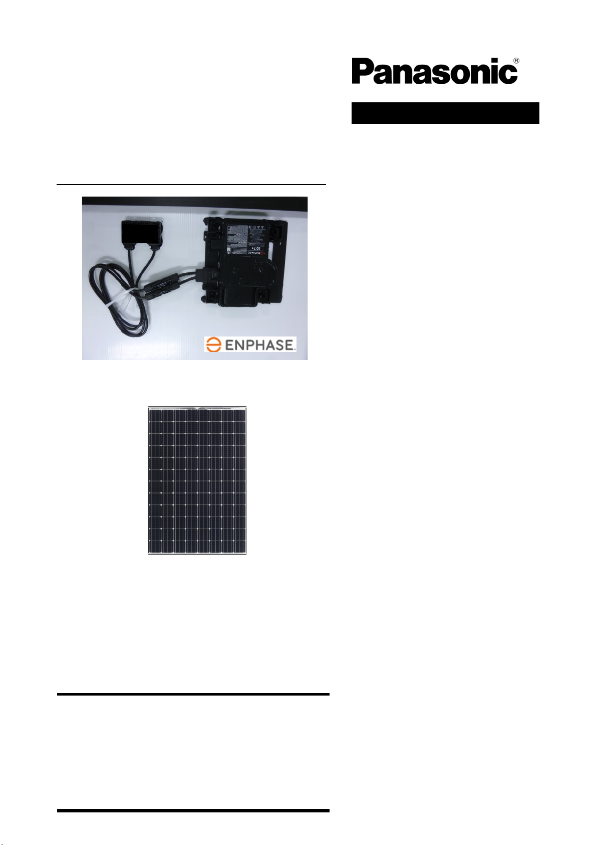
Microinverter IQ7X-96-ACM-US (Enphase Energy, Inc.)
VBHN330SA17E
Mounting on back of PV module
2
SAFETY PRECAUTIONS
This document is an installation
manual for a PV module with an
Enphase IQ7X-96-ACM-US Microin-
verter. For detailed information
about configuring and operating
the microinverter, please read
"ENPHASE Microinverters Installa-
tion Guide" .
https://enphase.com/sites/default/files/
downloads/support/IQ7-7plus-7X-Micro-
Manual-EN-US.pdf
All instructions should be read and
understood before attempting to
install, wire, operate, and maintain
the module.
The installation of modules requires
a great degree of skill and should
only be performed by qualified li-
censed professionals, including li-
censed contractors and licensed
electricians.
The installer assumes the risk of all
injury that might occur during instal-
lation, including the risk of electric
shock.
AC disconnects or breaker shall be
provided in the installation.
Before installing modules, contact
the appropriate authorities to deter-
mine permissions, installation and
inspection requirements should be
followed.
Confirm that the construction or
structure (roof, etc.) where the
modules are being installed has
enough strength.
Both roof construction and module
installation design have an effect on
the fire resistance of a building.
Improper installation may contrib-
ute to fire hazards. Additional de-
vices such as ground fault, fuses,
and disconnects may be required.
For a non-integral module or panel,
the assembly is to be mounted over
a fire resistant roof covering rated
for the application.
For modules mounted on roofs,
special construction or structures
may be required to help provide
proper installation support.
Do not install the module where
flammable gases or vapors are pre-
sent.
Do not use modules of different
specifications in the same system.
Follow all safety precautions of
other system components used.
In some areas, local electrical codes
may govern the installation and use
of modules.
WARNING
To avoid the danger of electric shock,
sparks, fire and injury
The modules generate electrical
energy when exposed to sunlight or
other light sources, so cover the
entire front surface of the modules
with a dense, opaque material such
as a cardboard box, during installa-
tion and handling of the modules.
The shock hazard increases as mod-
ules with nominal open-circuit volt-
age (Voc) in excess of 50 V, and/or
modules rated for maximum system
voltage in excess of 50 V.
Wear suitable clothing, gloves and
guards to prevent direct contact
with 30 VDC or greater.
Work only in dry conditions, with
dry modules and dry tools.
Children and unauthorized persons
should not be allowed near the
installation of modules.
Do not damage the back sheet, ca-
ble and connector of a module. Do
not use the PV module if conductive
part is found on the back sheet,
cable and connector. In such cases,
exchange to new PV module.
Do not disassemble the module, or
remove any parts installed by the
manufacturer.
Do not open a junction box's lid and
microinverter.
Do not touch the junction box and
microinverter terminals.
Do not change the wiring of bypass
diodes.
Do not connect or disconnect termi-
nals while modules generate elec-
tricity and connect electrical load.
Never leave a module unsupported
or unsecured.
CAUTIONS
To avoid the danger of injury, burn and
damage to the module
Use a module for its intended pur-
pose only.
Confirm that all other system com-
ponents are compatible, and they
do not subject the module to me-
chanical or electrical hazards.
Do not artificially concentrate sun-
light on a module.
Do not stand or step on a module.
When carrying a module, two or
more people should carry it by its
frame and wear non-slip gloves.
Do not carry a module by its wires or
junction box.
Do not drop a module.
Do not drop anything on the surface
of a module.
Do not hit the back sheet of a mod-
ule with the connector or other
things.
Do not disassemble a module, at-
tempt any repair, open the junction
box cover, nor remove any parts
installed by Panasonic. There are no
user serviceable parts within the
module or junction box.
Do not treat the back sheet or front
surface with paint or adhesives.
Do not use or install broken mod-
ules. If you find a breakdown such
as glass breakage, contact the pro-
fessional installer to replace it
promptly.
Do not touch a module unnecessari-
ly to avoid the risk of getting
burned. There is a possibility that
glass surface and frame are high
temperature.

3
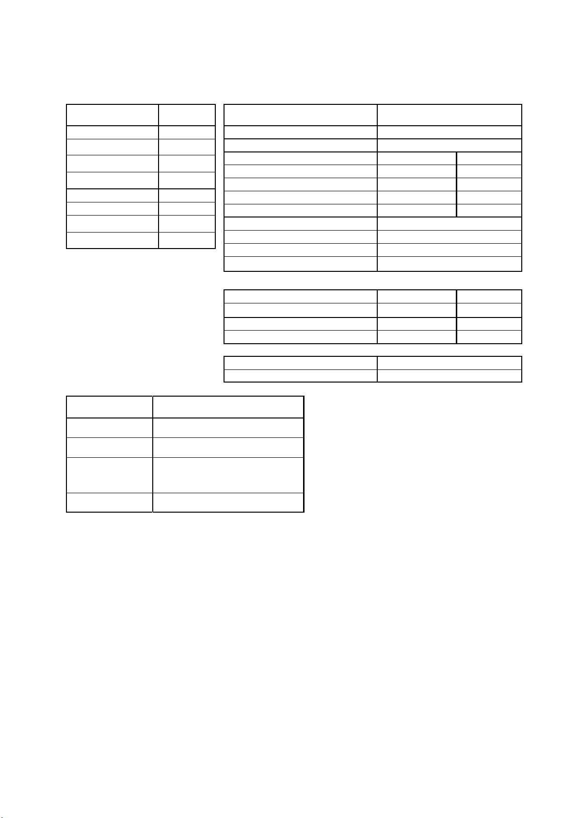
MODULE SPECIFICATIONS
Module specifications are shown in
Table 1-1 and Figure 1. (Electrical
specifications, mechanical specifica-
tions, module dimensions)
1) Rated electrical characteristics are
within the range of –5% to +10% of
the values measured at Standard
Test Conditions (STC). STC condi-
tions are; Irradiance of 1000W/m2,
25°C cell temperature, AM1.5 and
solar spectral irradiance per IEC
60904-3. Note: At the time of ship-
ment, Panasonic guarantees the
output level of its modules to be -0/
+10% against Rated Power in SPECI-
FICATIONS based on factory inspec-
tion at STC conditions.
2) Under real conditions, a photovolta-
ic module may experience condi-
tions that produce more current
and/or voltage than reported at
Standard Test Conditions. There-
fore, the Isc value of modules
should be multiplied by a factor of
1.25 to determine ampacity. An
additional factor of 1.25 may be
required for sizing conductors, fus-
es, disconnects, etc. Please refer to
section 690.8 of the National Electric
Code (NEC) for guidelines. The Voc
must be factored according to the
lowest recorded ambient tempera-
ture recorded for the location
where the modules will be installed.
Please refer to section 690.7 of the
NEC for more information regarding
voltage temperature factors.
VBHN330SA17E is equipped with a
Microinverter.
Microinverters are DC-AC inverters
connected to PV modules in order
to maximize power harvesting by
performing Maximum Power Point
Tracking (MPPT) at the module
level.
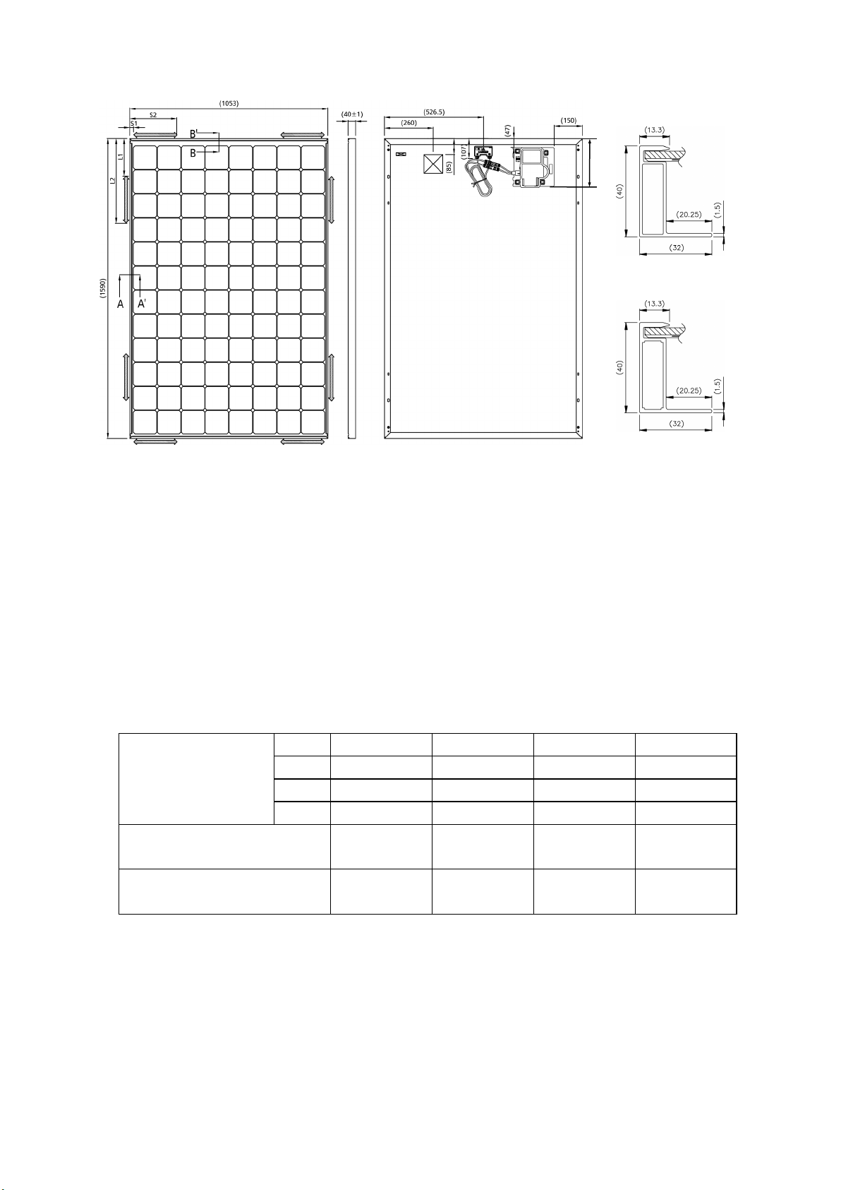
MECHANICAL LOADING
The modules should be mounted at
the four (4) quarter points by the
means shown in Figure 1.
This method offers a maximum load
shown as “Mount Location and
Load Resistance” in Table 1-2 in a
static state on the module surface.
Note: This mechanical loading value
was tested using the mounting de-
vice specified in section “MODULE
INSTALLATION”
As UL Certified Load Ratings, this
module meets design loads as be-
low.
1) Positive load with Long frame
mounting
・ 33 psf (0-450mm range from edge)
・ 75 psf (230-380mm range from edge)
2) Negative load with Long frame
mounting
・ 33 psf (0-450mm range from edge)
・ 61 psf(230-380mm range from edge)
・ 75 psf (230-345mm range from edge)
3) Positive load with Short frame
mounting
・ 33 psf (0-250mm range from edge)
4) Negative load with Short frame
mounting
・ 33 psf (0-250mm range from edge)
STANDARDS
VBHN330SA17E comply with the require-
ments of UL1703 (PV module) and UL
1741 (Microinverter, ENPHASE ENERGY,
Inc., Type IQ7X-96-ACM-US
FIRE CLASS OF PRODUCT
The fire rating of this module is valid
only when mounted in the manner
specified in the mechanical mounting instructions.
The models in this instructions are
suitable to maintain the System Fire
Class Rating A when used with a
Listed mounting system and a roof
covering that have been rated as a
Class A System when installed on a
steep slope roof and/or a low slope
roof with "Type 2" modules.
4
DC Electrical Specifications*
Model VBHN330SA17E
Cell Number in Series 96
Rated Power, Watts (Pmax) 330
Maximum Power Voltage
(Vpm)
58.0
Maximum Power Current
(Ipm)
5.70
Open Circuit Voltage (Voc) 69.7
Short Circuit Current (Isc) 6.07
Cell Type
Silicon hetero-
junction**
Factory Installed Bypass
Diodes
4
Mechanical Specifications
Model VBHN330SA17E
Length, mm (inches)
1590 (62.60)
Width, mm (inches) 1053 (41.46)
Frame Depth,
mm (inches)
40 (1.57)
Weight, kg (pounds)
19.5 (42.99)
Table 1-1. Module Specification
Silicon hetero-junction**: Mono crystalline silicon/amorphous silicon hetero-junction
AC Electrical Specifications
Model VBHN330SA17E
Peak Power Output 320VA
Maximum Continuous Output Power 315VA
Nominal (L-L) voltage 240Vac 208Vac
Nominal (L-L) voltage range 211 – 264V 183 – 229V
Nominal Output Current 1.31A 1.51A
Number of Maximum AC module 12 units 10 units
CEC Weighted Efficiency 97.5% 96.5%
Nominal Frequency 60Hz
Extended Frequency Range 47 – 68Hz
Power Factor Setting 1.0
Power Factor (adjustable) 0.7 leading / 0.7 lagging
*This specification shows the characteristics of the PV module not via the
microinverter.
UTILITY INTERCONNECTION VOLTAGE TRIP LIMITS AND TRIP TIMES
Overvoltage, Fast 288V / 0.16Sec 249.6V / 0.16Sec
Overvoltage, Slow 264V / 1.0Sec 228.8V / 1.0Sec
Undervoltage, Slow 211.2V / 2.0Sec 183.0V / 2.0Sec
Undervoltage, Fast 120V / 0.16Sec 104V / 0.16Sec
FREQUENCY TRIP LIMITS AND TRIP TIMES
OverFrequency 60.5Hz / 0.16Sec
UnderFrequency 59.3Hz / 0.16Sec
5
Figure 1. Module Dimension
(VBHN330SA17E)
Dimension in mm
Note) A module is installed using 4 points, symmetrical mounting
within setting range (Black arrows).
Note) Load Resistance shown above is UL Test-Load.
Design load is a value obtained by multiplying the above value by two thirds.
Table 1-2. Mount location and Load Resistance
Mounting location range
(mm)
L1 0 230 230 -
L2 450 380 345 -
S1 - - - 0
S2 - - - 250
Load Resistance (Positive Load)
50 psf 112 psf 112 psf 50 psf
(2400 Pa) (5400 Pa) (5400 Pa) (2400 Pa)
Load Resistance (Negative Load)
50 psf 91 psf 112 psf 50 psf
(2400 Pa) (4400 Pa) (5400 Pa) (2400 Pa)
Side
Front
Backside
Section B-B
Section A-A
Max 270mm
6
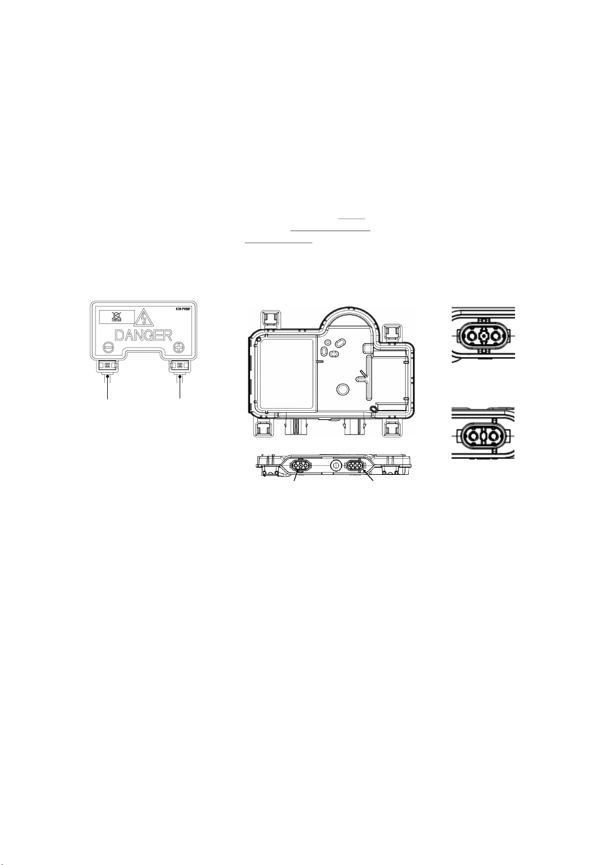
Figure 2-1. Junction Box
Positive ( + ) Negative ( - )
JUNCTION BOX, MICROINVERTER
AND TERMINALS
Modules equipped with one junc-
tion box contain terminals for both
positive and negative polarity, and
bypass diodes.
Each terminal is dedicated to one
polarity (with the polarity symbols
engraved onto the body of the junc-
tion box) . See Figure 2-1.
A microinverter has an input / out-
put terminal. See Figure 2-2.
Each terminal is provided with facto-
ry installed lead cables and a latch-
ing connector. Always use these
connectors and do not detach them
from cables.
The PV module and a microinverter
come pre-wired. Each module has
two #12 AWG type PV-wire stranded
sunlight resistant output cables each
terminated with connectors. The
positive (+) terminal has a male
connector while the negative (-)
terminal has a female connector.
Latching connectors are type IV and
supplied by STAUBLI ELECTRICAL
CONNECTORS AG, which are listed
by UL.
Figure 2-2. Output / input terminal of a Microinverter
Side view
Top view
Input terminal
Output terminal
Enlarged view of
output terminals
Enlarged view of
input terminals
7
BYPASS DIODE
When the module is shaded partial-
ly, it may cause reverse voltage
across cells, because the current
from other cells in the same series is
forced to flow through the shaded
area. This may cause undesirable
heating.
The use of a diode to bypass the
shaded area can minimize both
heating and module current reduc-
tion.
All modules are equipped with fac-
tory installed bypass diodes. The
factory installed diodes provide
proper circuit protection for the
systems within the specified system
voltage, so that you do not need
any other additional bypass diodes.
Specification of bypass diode is as
follows; Type: Number of bypass
diode: 4 diodes, Number of series
cells per bypass diode: 24 cells /
diode. See Figure 3.
INSTALLATION GENERAL
Please read this guide completely before
installation or use of the modules.
OPERATING CONDITIONS
Panasonic recommends that modules be
operated within the following Operating
Conditions. An installation location with
conditions beyond the Operating Condi-
tions or with other Special Conditions
(see below) should be avoided. Operat-
ing Conditions of Panasonic modules are
as follows:
1) The modules should be operated only
in terrestrial applications. No space or
other Special Conditions.
2) The operating module temperature
must be within –30°C (-22°F ) to 85°C
(185°F ). And the operating ambient
temperature must be within –30°C (-22°
F ) to 60°C (140°F ).
3) The wind pressure load of the installa-
tion site should be less than Load Re-
sistance shown in “Mount Locations and
Load Resistance” refer to table 1-3.
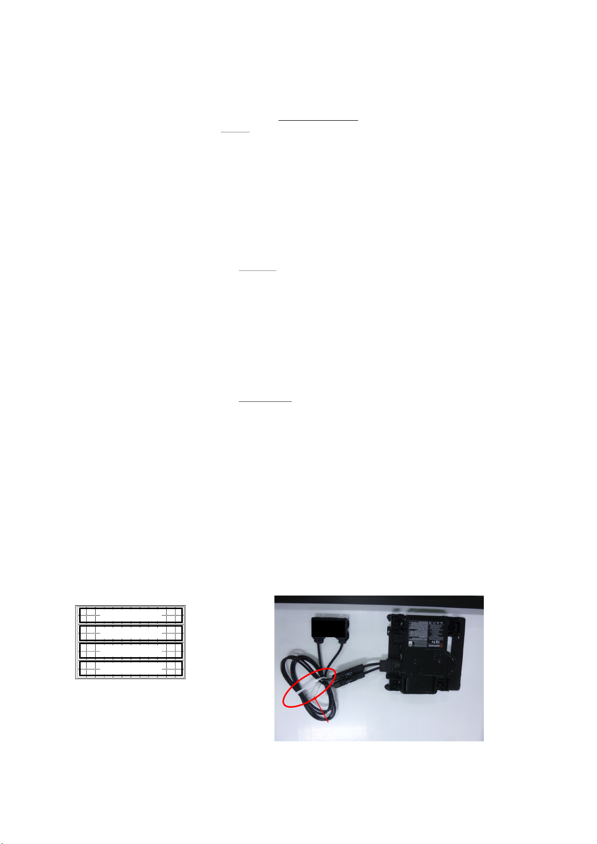
UNPACKING AND HANDLING
Do not hit the back sheet of a mod-
ule with the connector when un-
packing and handling.
Please do not expose the connector
to rain water and dust .
To avoid damage to the back sheet
by the connector, Do not cut the
string binding the cables of junction
box. See Figure 4.
Do not handle modules while hold-
ing their cables, junction box or
microinverter. Handle them while
holding the frame with both hands
in any situation.
The anti-reflection glass of a module
is easily soiled, when it is grasped by
hand or hand gloves. So it is recom-
mended to hold frames when carry-
ing or installing the solar module.
When cables and connectors touch
the surface of the glass, it may soil
the surface too. It is also recom-
mended to avoid contact of cables
and connectors with surface of the
glass. (If the glass surface becomes
dirty, see section of "anti-reflection
glass surface cleaning".)
Figure 4. The string binding the cables of Junction box
24 cells /
24 cells /
24 cells /
24 cells /
Figure 3. Number of series
cells per bypass diode
Do not cut the string binding the cables of Junction box
8
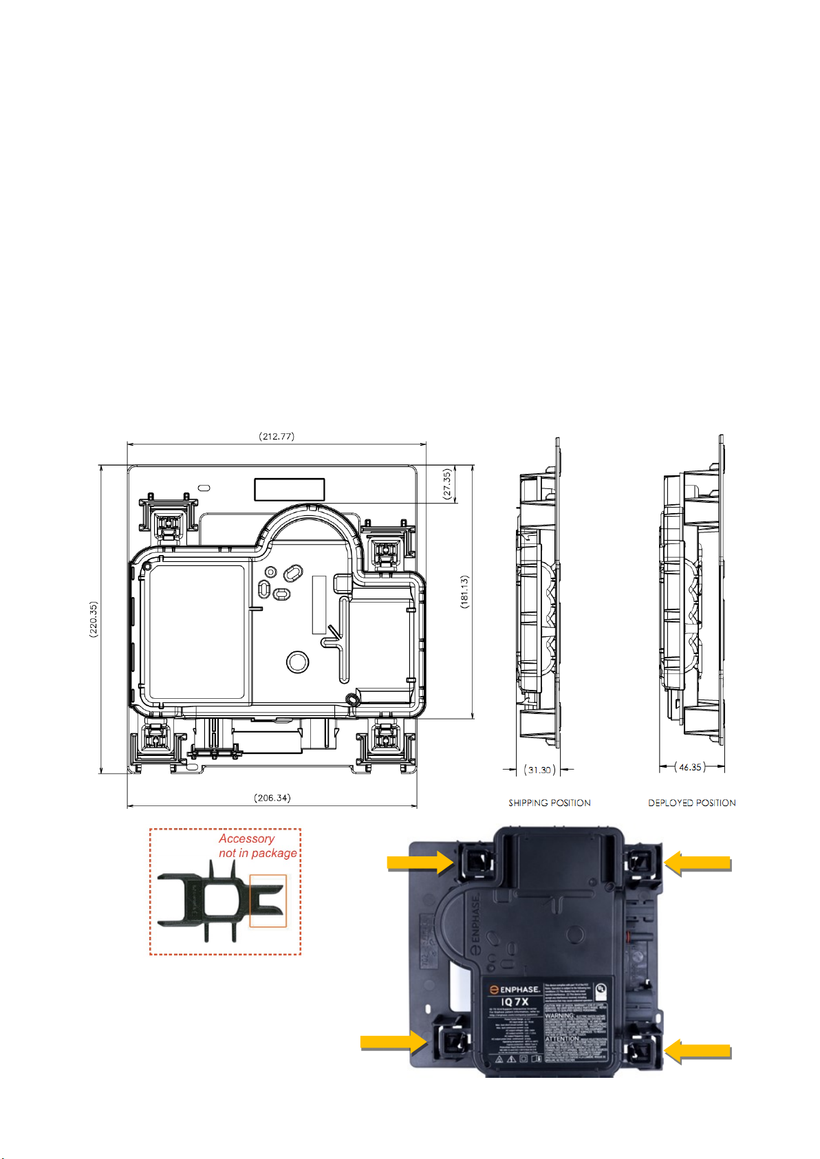
Figure 5. How to move to the shipping
position using the Enphase
Disconnect Tool.
PREPARE THE MICROINVERTER
Before installing the PV module the
microinverters must be lifted from
the shipping position. On the
ground, turn the PV module so that
the microinverter faces you.
Using both hands, lift the microin-
verter up. You will hear four clicks as
the microinverter locks into the in-
stallation position (Deployed posi-
tion). Ensure that the four latches
are locked, and the microinverter is
not tilted.
Place the PV modules on the roof.
Do not place the PV modules in such
a way that places pressure on the
microinverter.
If you need to service, you can return
the microinverter to the shipping
position using theEnphase Discon-
nect Tool. Use the tool to depress the
four locking switches on each corner
of the microinverter to return it to
the shipping position.(See Figure.5)
If the problem persists, contact Cus-
tomer Support at Website as follows,
https://enphase.com/en-us/company/
contact-us
POSITION THE ENPHASE Q CA-
BLE
Plan each cable segment to allow
drop connectors on the Enphase Q
Cable to align with each PV module.
Allow extra length for slack, cable
turns, and any obstructions.
Mark the approximate centers of
each PV module on the PV racking.
Lay out the cabling along the in-
stalled racking for the AC branch
circuit. Make sure that the cable is
positioned in a way that allows you
to connect it to the microinverter.
Cut each segment of cable to meet
your planned needs.
When transitioning between rows,
secure the cable to the rail to pre-
vent cable damage or connector
damage. Do not count on connector
to withstand tension.
When transitioning, Please do not
damage at cable or connector.
 Loading...