

Page 1
Panasonic
Digital Business System
DBS Release Notes
Version 1
(Preliminary)
Document Number: DBS-EXI O-705
Part Number: 550X07901
June
Technical Manuals Online! - http://www.tech-man.com
Page 2
Contents
Introduction
Compatibility.. ........................................................
FF-Key Progr
Additional Serial Port
Networking Capability
Modification to Toll Restriction Service
Maximum Time Priority Route Tables.
Modification to
.......................................................
...............................................
.................................................
..................................................
..................................................
............................................
Separate Volume Control for Internal vs. CO calls
Analog Adapter
MSG (Message) Key
and EM/24
.......................................................
....................................................
..............................................
.
Key Arrangement
.................................................
.............................................
........................................
................................................
Signaling Types.
.......................................
.................................
.....................................
......................................
..................................
.......................
............
5
.
.
...6
.
...6
...6
6
6
...7
...7
7
7
7
...7
...8
Installation Notes
Desi Strip Cover
Key Telephone Wall Mounting Instructions.
New Phone Features
Directory Mode
Separate Speaker Volume for Internal vs. CO calls.
MSG (Message) Key
Console
EM/24
Key Arrangement
..................................................
..................................................
..............................................
....................................................
......................................
.......................................................
...................................................
...................................................
Key Arrangement.
..............................................
.....................................
...8
..............................
...........................
Contents
8
9
9
11
15
6
8
9
19
9
22
l
Page 3
Technical Manuals Online! - http://www.tech-man.com
Page 3
DBS Release Notes
CPC-EX, Version 1 .O (Preliminary)
Panasonic@
June
Speed-Dial Enhancements.
Additional Serial Port on CPC Card
Networking
....................................................
.........................................
..................................
Network Extension to Extension Calling.
Call Forwarding to Network Extensions
Paging Across Network Nodes.
Network Route Selection
..........................................
...............................................
Remote
SMDR Network Support
................................................
Independent Node Attendant Assignment
Settings Modified for Networking
Extension Number Digits
........................................
...........................................
SMDR Printing Mode 1: Outbound and Inbound.
..................................................
Extension Numbers.
...............................................
................................................
Other Changes to Programming Addresses
New Programming Addresses
............................................
28
32
35
5
..................................
...................................
7
37
..................................
........................
..3 9
..4 0
.................................
41
Modification to
Maximum Time Priority Route Tables
Support
Hardware Requirements
Modifications to SMDR
Modification to
Outgoing Signaling Type.
Restriction Service
.................................
....................................................
.................................................
.............................................
Signaling Types
..................................
...............................................
..............................
.
42
45
46
46
47
50
0
Page 4 l Contents
Technical Manuals Online! - http://www.tech-man.com
Page 4
Panasonic@
CPC-EX, Version
Release
1 .O
Notes
(Preliminary)
Introduction
CPC-EX Version 1.0 offers the following new enhancements to the DBS phone system:
Compatibility
CPC-EX Version 1.0 supports all features of CPC-B Version 7.1 (with the exception of TSAPI
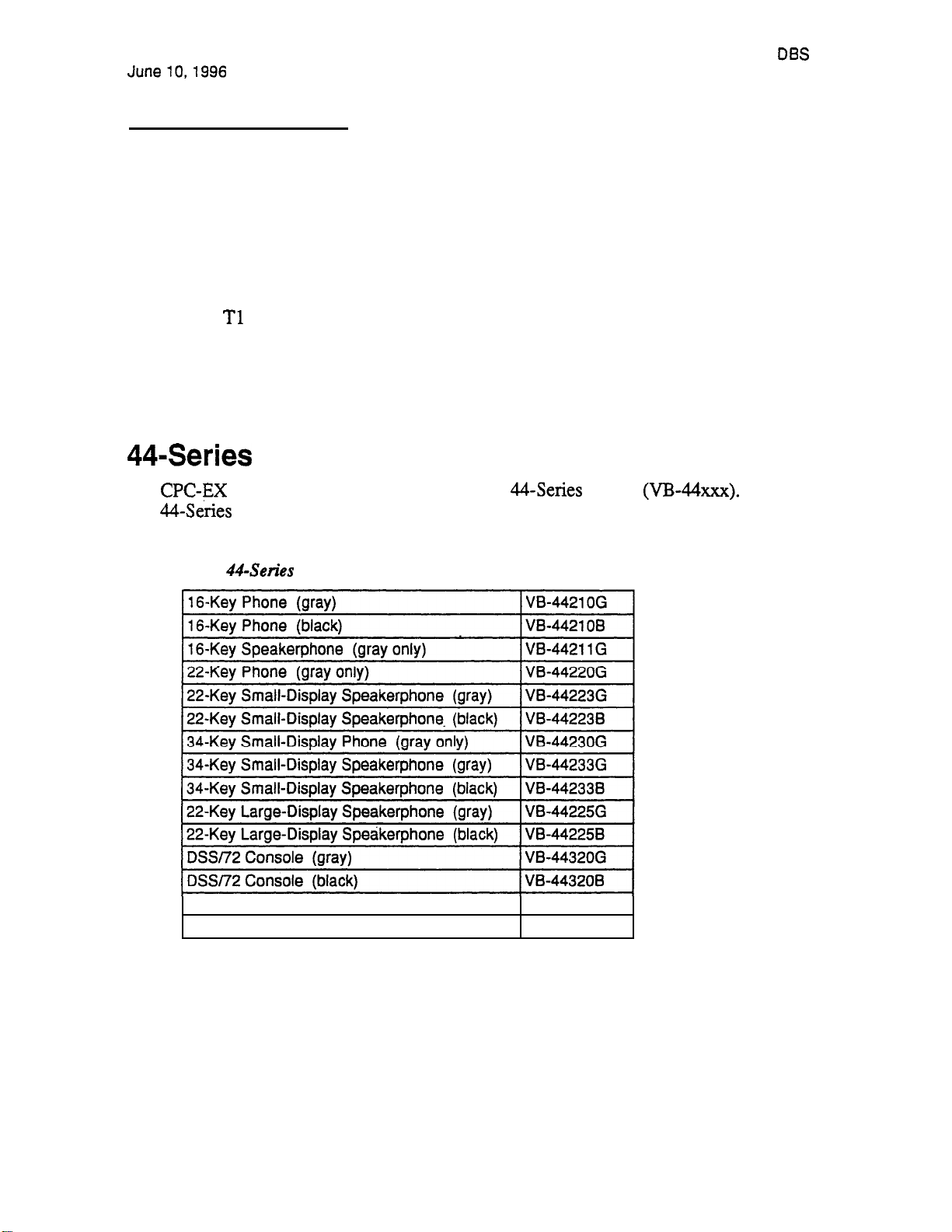
support). In addition, CPC-EX Version 1.0 adds support for new features, including the 44-Series
phones,
The CPC-EX card can be installed into an existing DBS cabinet, with no hardware modifications.
CPC-EX software uses existing CPC-B programming addresses, with the same numbering.
Additional addresses have been added for new CPC-EX features.
Networking, and ISDN.
Phone Support
provides full support for Panasonic’s
black.
Table 1.
EM/24 Unit (gray)
EM/24 Unit (black)
Phones
phones
W-4431 OG
VB-4431 OB
Table 1 below lists all
Technical Manuals Online! - http://www.tech-man.com
Introduction l
Page 5
Page 5

Release Notes
CPC-EX, Version 1 .O (Preliminary)
Panasonic@
June
New DBS features that can be executed on the
phones are described below.
Directory Mode
On the new small-display phones, you can scroll through SSD names, PSD names, or extension
names and select a displayed name for dialing.
Variable
The new small-display phones provide one-touch access to various features displayed during each of
the following call states: 1) during an intercom call; 2) during CO dial tone; 3) during a trunk call;
and 4) after dialing a busy extension.
Handset Mute
The new large-display phone now contains a MUTE key, and a new mute feature is available on all
phones. Pressing the MUTE key during an off-hook call will block audio from the handset
transmitter to the outside party. You can still hear them, but they
can’t
hear you.
Off-Hook Monitoring
If you press the ON/OFF key during an off-hook call on any 44-series speakerphone, the other
party’s voice will be heard through both the handset and the speaker. This allows a third party to
hear both sides of a conversation. Note: This feature does not activate your phone’s microphone
audio will be transmitted only through, your handset.
Separate Volume Control for Internal vs. CO calls
CPC-EX allows you to establish separate speaker volumes for internal and external calls.
Analog Adapter
The new large-display phone can be enhanced with an analog port adapter which allows you to
connect to an analog device such as a FAX or modem to the phone. This allows the same phone to
be alternately used for analog or digital communications.
MSG (Message) Key
A new MSG key on the large-display phone will perform Auto-Callback (automatically dialing the
extension that sent a “Message Waiting” to your phone), or Auto-Answer Message (automatically
dialing your voice mailbox).
Key Arrangement
The keys on the new consoles are arranged differently, affecting the text layout and default extension
numbers assigned to these keys.
Page 6 l Introduction
Technical Manuals Online! - http://www.tech-man.com
Page 6

Panasonic@
June
FF-Key Programming
Release
CPC-EX, Version 1 .O (Preliminary;
Because
up to 8 digits (not 6) into an
Networking adds the capability of 4-digit extension numbering, you can now program
Speed Dial Enhancements
CPC-EX supports up to 500 System Speed Dial (SSD) numbers. CPC-EX also allows SSD codes to
be chained, or “linked”, to another SSD number, and either PSD or SSD codes to be chained to a
PSD number.
Additional Serial Port
The CPC-EX card contains an on-board serial port (Serial Port 2) which can be used for Bus
Monitor/Maintenance. This allows remote maintenance to be accomplished without disconnecting
SMDR cabling.
Networking Capability
Up to 4 DBS’s can now be connected together via
DBS’s can be located in the same building, in separate buildings in a campus-type environment, or at
remote locations in separate states. Networked DBS’s use 4-digit extensions, with the first digit of
the extension number identifying the DBS site.
interface to form a DBS phone network. The
Each site requires its own DBS cabinet with a CPC-EX card and a
addresses are included in CPC-EX software for setting up the
Reference Manual for complete instructions)
card. ‘New programming
Network. (see the
Networking
Modification to Toll Restriction Service
The program address for TRS Operator Access (FF7 has been modified to allow an
extension to dial
phone numbers, even if “O-only” dialing is denied.
Maximum Time Priority Route Tables
CPC-EX allows a maximum of 8 Time Priority Route Tables (not 15) to be used during LCR
programming. Since few systems use more than 3 Time Priority Route Tables, this change will
allow the saved memory space to be used for future enhancements.
SMDR Modifications
SMDR reports contain several new call types and other parameters due to CPC-EX support of
Networking and ISDN calls.
Technical Manuals Online! - http://www.tech-man.com
Introduction l
Page 5
Page 7
Release Notes
CPC-EX, Version 1 .O (Preliminary)
Support
Panasonic@
June
CPC-EX
program address for Trunk Circuit Type
ISDN. New programming addresses have also been added in CPC-EX to support ISDN. (See
ISDN Reference Manual for complete instructions.)
Modification to
To allow easier programming of E&M trunks, CPC-EX uses “Wink Start” (not “Trnmediate Start”)
as the default for
supports
ISDN-PRI (Integrated Services Digital Network --
(trunk #)# 21#
has been modified to allow for
Signaling Types
Incoming and Outgoing Signal Types.
Rate Interface).
the
The
Installation Notes
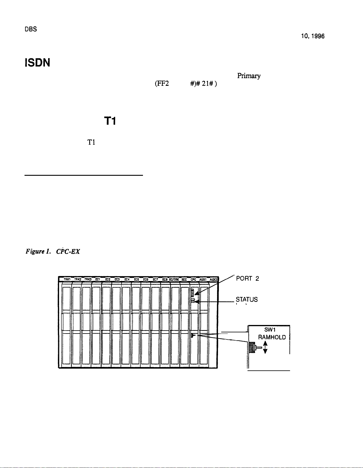
CPC-EX Installation
Use normal installation procedures to install the CPC-EX. The following illustration shows an
installed CPC-EX.
SERIAL
LED
RAMCLR
I
Page 8 l Installation Notes
Technical Manuals Online! - http://www.tech-man.com
Page 8
Panasonic@
June
CPC-EX, Version 1 .O (Preliminary)
DBS Release Notes
Key Telephone Installation
Desi Strip Cover
Tine 44-Series Key Telephones are shipped with a thin green protective film over the Desi strip
cover. Be sure to remove this film from both sides of the Desi cover before placing the phone in
service.
Key Telephone Wall Mounting Instructions
The following procedures apply to
Key Telephones only. Please be sure
to
follow these
procedures exactly. Removing the desk stand incorrectly can result in damage to the telephone
and/or desk stand.
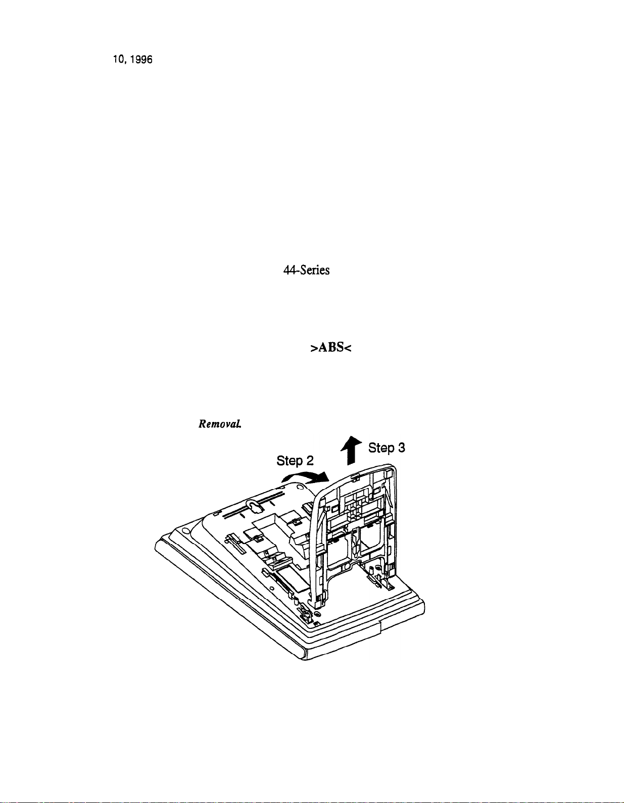
1. Place the telephone face down on a flat surface.
2. Grasp the top of the desk stand (at the
label) and pull up the end to 90” vertical (refer
Step 2 in Figure 2j. The stand will click as it releases from the plastic securing latches.
3. Lift the desk stand as shown in Step 3 of Figure 2.
Figure 2.
Desk Stand
to
Technical Manuals Online! - http://www.tech-man.com
Installation Notes l
Page 9
Page 9
Release Notes
CPC-EX, Version 1 .O (Preliminary)
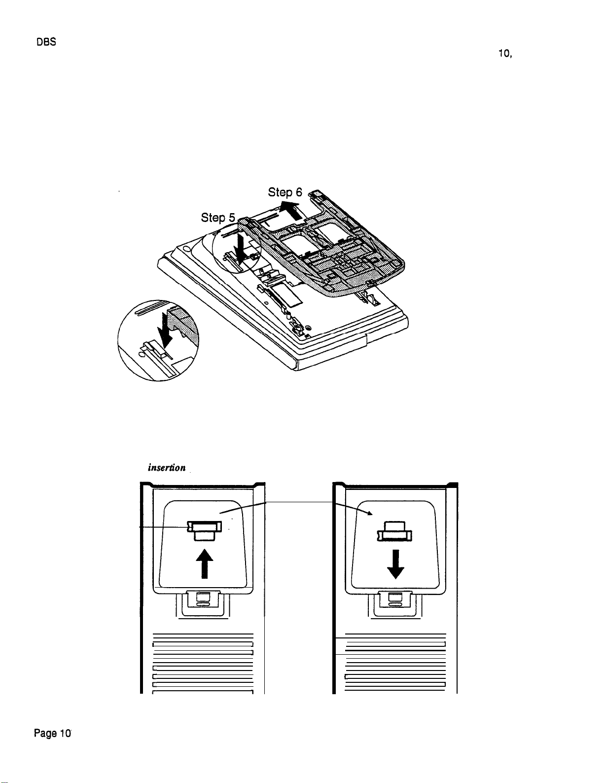
4. Rotate the desk stand 180”. In this position it doubles as a wall mount bracket.
5. Insert the wall mount bracket into the mounting guides as shown in Figure 3.
6. Slide the wall mount bracket onto the telephone.
Panasonic@
June
1996
Figure 3.
.
7. While viewing the front of the telephone, find the handset guide located just below the
Inserting the wail mount bracket (rotated desk stand)
hookswitch (see Figure 8).
8. Slide the handset guide out, rotate 180” so that the holding clip is exposed, and reinsert.
Figure 4.
Handset guide
Handset
Guide
l
Installation Notes
for wall mounting, key telephone
r
1
I
3
r
t
I
I
I
Technical Manuals Online! - http://www.tech-man.com
Page 10
Panasonic@
June
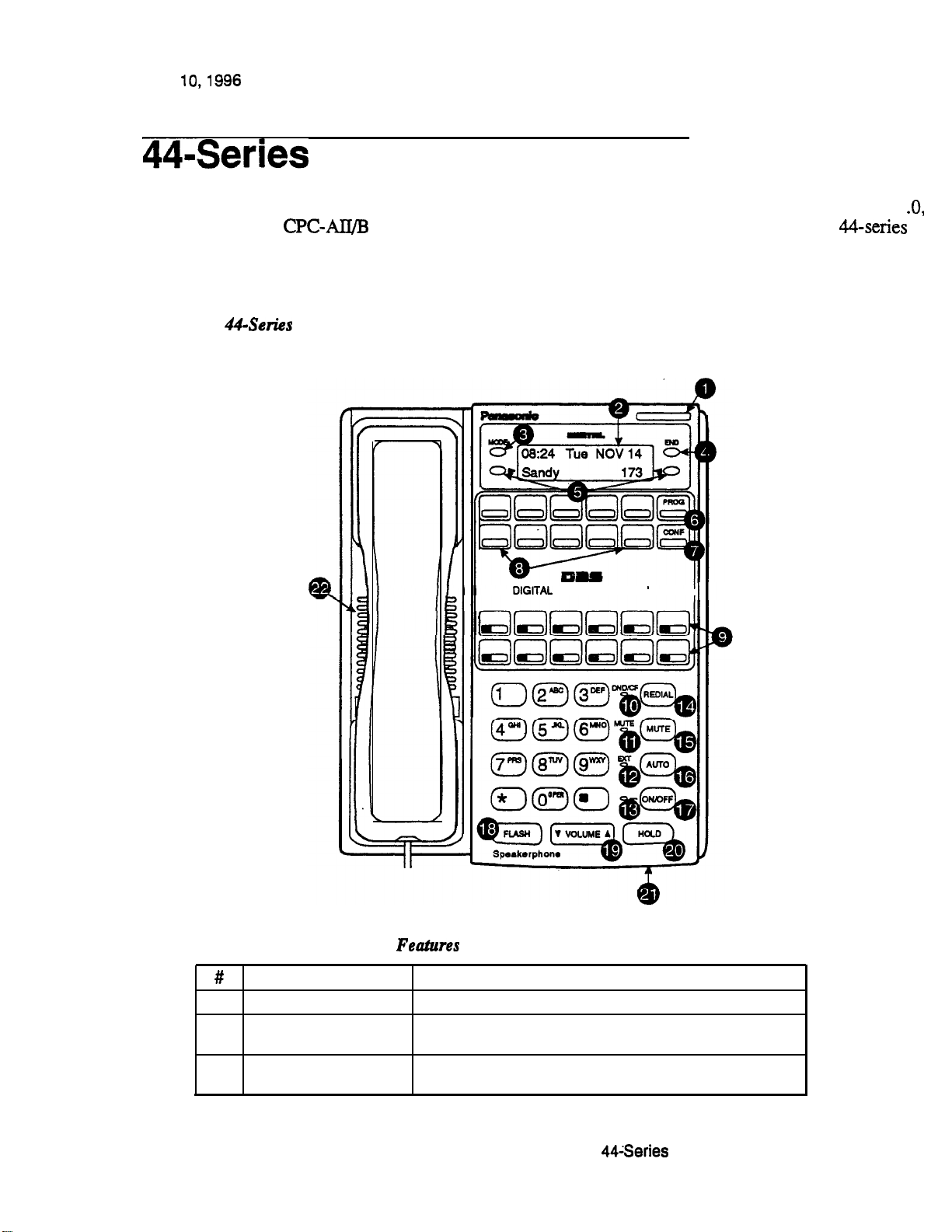
Figure 5.
DBS Release Note!
CPC-EX, Version 1 .O (Preliminary
New Phone Features
Note: The new features introduced with these phones are supported by CPC-EX Version 1
phones with previous DBS versions, but the new features won’t be supported.
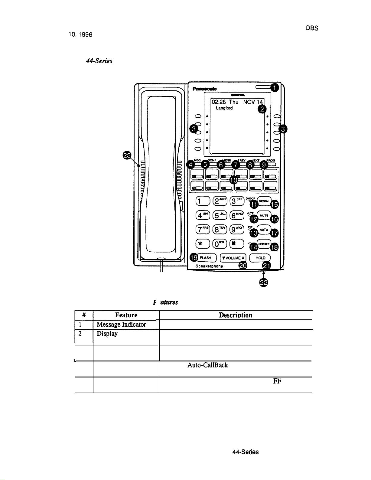
Table 2. Small-Display Phone
Feature
1
Message
2
3
Display Displays information about phone’s status, menus,
Mode Key
Indicator
BUSINESS SYSTEM
II
Description
Indicates that you have a message.
dialing directories, and text message information.
Used to change display modes from default to direc-
tory mode.
Technical Manuals Online! - http://www.tech-man.com
New Phone Features
l
Page 11
Page 11
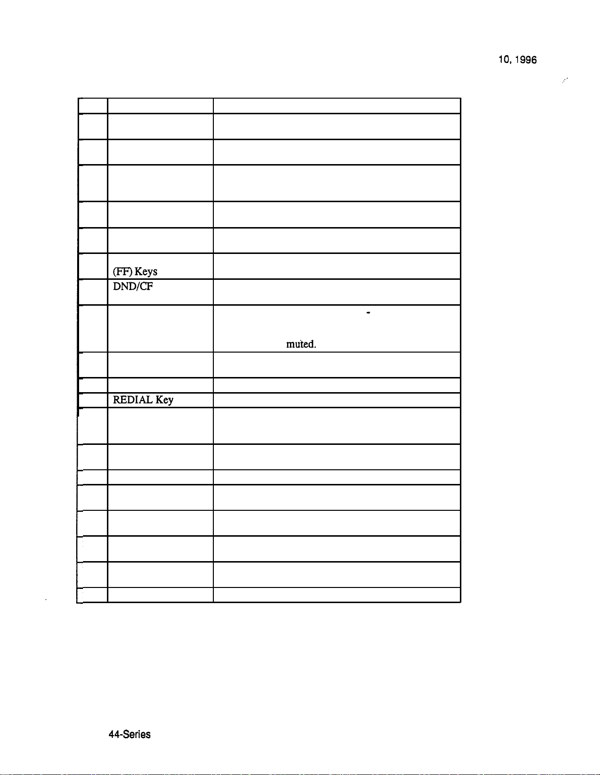
DBS Release Notes
CPC-EX, Version 1 .O (Preliminary)
Panasonic@
June
#
4
5
6
7
8
9
End Key
Select Keys
PROG Key
CONF Key
One-Touch Keys
Flexible Function
10
11
MUTE Indicator
12
EXT Indicator
13
ON/OFF Indicator
14
15
MUTE Key
AUTO Key
16
17
ON/OFF Key
FLASH Key
18
19
VOLUME Key
20
HOLD Key
21
Microphone
22
Speaker
Feature
Indicator
.
Description
Used to exit directory
mode
and return display to
default mode.
Used to select and dial System Speed Dial, Personal
Speed Dial, and Extension numbers from a directory.
Used to program FF and one-touch keys and to adjust
ringer volume. Depending on the setup of your sys-
tem, may also
be used to transfer calls.
Used to establish conference calls, check FF key and
one-touch features, and scroll through messages.
Used to make outside calls or to access call-handling
features.
Used to access outside lines or to access call-handling
features.
Indicates that Do-Not-Disturb, Call Forwarding, or
Absence Message is set.
Indicates that your voice is muted
i.e., party on the
other end cannot hear you. Lights solid when your
hands-free microphone is muted and flashes when
your handset is
Lights when you are on a call; flashes when you hold a
Cdl.
Lights when ON/OFF key has been pressed.
Used to redial last outside number dialed.
Used to activate/deactivate MUTE function. When
activated, the party on the other end cannot hear you.
(See item 11, MUTE Indicator.)
Used to access speed dialing, enter account codes, or
for message waiting answer/cancel.
Used to make a call without lifting handset.
Used to end an outside call and to restore dial tone
without hanging up receiver.
Used to adjust level of tones, background music, ring-
ing, receiver volume, and display contrast.
Used to hold calls, to retrieve held calls, and to com-
plete FF key programming.
Used to talk with other party without using the hand-
set.
Outputs tones and voice at your extension.
Page 12
.
New Phone Features
Technical Manuals Online! - http://www.tech-man.com
Page 12
Panasonic@
June
Figure 6.
Release Notes
CPC-EX, Version 1 .O (Preliminary)
S 173
PERSONAL DIAL
SYSTEM DIAL
EXTENSION
FUNCTION
HELP
.
Table 3. Large-Display Phone
Indicates that
Displays information about phone’s status, menus,
dialing directories, and text message information.
3
Soft Keys
Used to make outside calls or to access call-handling
features.
4
MSG Key
Used for
a text message or to access voice messages.
5
CONF Key
Used to establish conference calls, check
one-touch key settings, and scroll through messages.
Technical Manuals Online! - http://www.tech-man.com
YOU
have a message.
to a telephone which has left
I
I
and
New Phone Features
l Page 13
Page 13
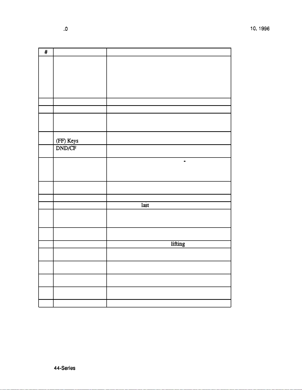
DBS Release Notes
CPC-EX, Version 1
6
MENU Key
7
PREV Key
8
NEXT Key
9
PROG Key
10
Flexible Function
11
12
MUTE Indicator
EXT Indicator
13
14
ON/OFF Indicator
15
REDIAL Key
16
MUTE Key
17
AUTO Key
18
ON/OFF Key
19
FLASH Key
20
VOLUME Key
21
HOLD Key
22
Microphone
23
Speaker
(Preliminary)
Feature Description
Used to return to the Main Menu screen. The default
Main Menu screen contains the following items:
l
PERSONAL DIAL
l SYSTEMDIAL
l
EXTENSION
l FUNCTION
l HELP
Used to return to the previous menu.
Used to advance to the next menu.
Used to program FF and one-touch keys and to adjust
ringer volume. Depending on the setup of your system, may also be used to transfer calls.
Used to access outside lines or to access call-handling
Indicator
features.
Indicates that Do-Not-Disturb, Call Forwarding, or
Absence Message is set.
Indicates that your voice is muted
other end cannot hear you. Lights solid when your
hands-free microphone is muted and flashes when
your handset is muted.
Lights when you are on a call; flashes when you hold a
call.
Lights when ON/OFF key has been pressed.
Used to redial
outside number dialed.
Used to activate/deactivate MUTE function. When
activated, the party on the other end cannot hear you.
(See item 12, MUTE Indicator.)
Used to access speed dialing, enter account codes, or
for message waiting answer/cancel.
Used to make a call without lifting handset.
Used to end an outside call and to restore dial tone
without hanging up receiver.
Used to adjust level of tones, background music, ring-
ing, receiver volume, and display contrast.
Used to hold calls, to retrieve held calls, and to com-
plete FF key programming.
Used to talk with other party without using the hand-
set.
Outputs tones and voice at your extension.
Panasonic@
June
i.e., party on the
Page 14
l
Technical Manuals Online! - http://www.tech-man.com
Page 14
June
Directory Mode
DBS Release Notes
CPC-EX, Version 1 .O (Preliminary)
Description
Operation
This new feature applies to the
small-display phone only (i.e., phones
with a 2-line LCD display).
In Directory Mode, you can use the phone’s select keys (as well as other keys) to
scroll through a directory of existing System Speed Dial (SSD) names, Personal
Speed Dial (PSD) names, or extension names -- and select one to dial.
l
For example, ifyou can’t remember the party’s extension number or
speed-dial number to which you want to transfer a call on hold, you can use
Directory Mode
the number and execute the transfer.
The select keys on the 44-series smaildisplay phone are located next to the
display’s 2nd line. Pressing select key 1
on the left) or select key 2
on
the right) will access the displayed-directory.
To use Directory Mode:
1.
Press the MODE key to turn Directory Mode on. The 2nd line of the
LCD will display “SSD” on the left and “PSD”on the right.
l
Press the MODE key again to access the directory for extension
names. The 2nd line of the LCD will display “EXT” on the left.
2.
Press the
names; or the
select key to access the directory of existing SSD or EXT
select key to access the PSD directory. The 2nd line will
show two speed-dial or extension names at a time (the first 7 characters of
each name), beginning with the A’s.
3.
To scroll through the names (two at a time), press the #key. To
back-scroll, press the * key.
4.
To jump to another letter in the directory, press the numeric key for it.
For example, press the “6” key to jump to the M’s, N’s, and
M’s will appear
jump to the
Press “6” again to jump to the N’s, and again to
This doesn’t work for PSD names unless the
The
system is a DBS 824 CPC-M Version 2.0 or higher, which allows up to
40
l
For names beginning with Q or
5.
When the correct speed-dial or extension name is displayed, you can
use the 1 key.
execute the dialing of its speed-dial or extension number by pressing
the select key that points to it
if the name is displayed on the left; or
if the name is on the right).
Technical Manuals Online! - http://www.tech-man.com
l
Page 15
Page 15
Release Notes
CPC-EX, Version 1 .O (Preliminary)
l
Or,
the END key or go on-hook.
to exit
the directory without selecting a number to dial, press
Panasonic@
June
Notes
Incompatibility with older phone versions.
new 44-Series phones only.
Hot Dial Pad and Directory Mode. The
will not work on an extension in Directory Mode.
Variable Mode
Description
This new feature
with a a-line LCD display).
When the phone is in Variable Mode, the features for Flexible Function Screen
select keys 1 and 2 will display during each of the following call states:
Call State
l
During an intercom call
l During CO
l
During a trunk call
l
After dialing a busy extension FF3
applies
Directory Mode is available on the
Hot Dial Pad feature (FF3 ExtPort#
to the 44-series small-display phone only (i.e., phones
Proaram Address*
FF3
FF3
Operation
l
In these addresses, you assign a Flexible Function Screen (2539) to appear on
the extension while it is in the call state.
The select keys on the
left and right of the display’s 2nd line.
select key 2
on the right) will perform the displayed feature.
small-display phone are labeled
Pressing select key 1
and
to the
on the left) or
To use Variable Mode:
1.
Activate Variable Mode by pressing
l
When you dial ‘61 in the above sequence, the 1st line of the LCD
ON/OFF
ON/OFF.
will display “Variable md ON”. The display will return to normal
when you press the second
l
The
l
61 code toggles Variable Mode on and off. Press
ON/OFF
2.
While the extension is engaged in an intercom call, the 2nd line will
again to turn Variable Mode off.
ON/OFF.
ON/OFF
l
61
display select key 1 and 2 features from the Flexible Function Screen
assigned to display
extension receives CO dial tone (FF3 ExtPort#
The same applies when the
during a trunk
Page 16
.
New Phone Features
Technical Manuals Online! - http://www.tech-man.com
Page 16

Panasonic@
June
Release Notes
CPC-EX, Version 1 .O (Preliminary)
Notes
call (FF3
and after dialing a busy extension (FF3
l
Use existing addresses
2#
thru
to assign select key
features to Flexible Function Screens.
l
Use existing addresses
l
Select key features for
2# 7#
Fixed
Function Screens will not appear on
to assign screen text.
small-display phones.
While the select key feature is displayed, you can execute the feature
3.
by pressing the
Variable Mode
into an FF-key: In progr
or
select key.
with an FF-Key.
mode, press FF5
You can program the
l
6 1 code
The FF-key will toggle Variable Mode on/off while the extension is idle or in an
off-hook/dial-tone state. The FF-key LED will remain lit (red) while Variable
Mode is “On”. (You can also use a one-touch key to toggle Variable Mode on and
however, one-touch keys do not contain an LED to indicate when Variable
Mode is on.)
Variable Mode After Power-Cycling.
If Variable Mode is “On”, the extension
will stay in Variable Mode even after power-cycling (system is powered down,
then powered back up).
Incompatibility with olderphone versions.
Variable Mode is available on the new
44-Series phones only.
Conditions under which Variable Mode does not work.
Variable Mode will be
temporarily overridden under the following conditions: during an incoming
message state, hold state, message-waiting state, or call-waiting state. Incoming
messages include:
CO Queuing
Incoming [trunk no.]
no.]
no.]
H-Recall
Call wait
no.]
Recall Hnt [Hunt Group no.]
DISA Incoming
Call [extension no.]
Transf [extension no.]
Recall [trunk no.]
HOLD Recall
Technical Manuals Online! - http://www.tech-man.com
New Phone Features
l
Page 17
Page 17

DBS Release Notes
CPC-EX, Version 1
(Preliminary)
Handset Mute
Panasonic@
June
Description
Operation
Notes
While using the handset (not on speaker) during a phone conversation, you can
press the MUTE key to block audio path to the other
party -- you
can still hear
them, but they can’t hear you. This feature is called “Handset Mute.”
1.
To turn on Handset Mute while using the handset, press the MUTE key.
l
The MUTE indicator lamp (LED next to MUTE key) will flash.
l
The handset transmitter will be muted. You will still be able to hear
the other party, but they can’t hear you.
2.
To turn off Handset Mute, do one of the following:
-- press the MUTE key again,
press HOLD to place the
--
replace the handset on-hook; or
on hold;
-- press the flashing FF-key to answer another call.
l
Note: This will drop the first call unless Key Bank Hold is enabled
l
The MUTE indicator lamp will stop flashing.
Headset
the phone to handle calls
Use. The Handset Mute feature also works if you are using a headset on
activates Headset mode).
Speakerphone
Use. The MUTE key works the same as before (mutes the
microphone) when you are on speaker. The MUTE lamp lights steadily when the
microphone is muted, and flashes when the handset is muted.
The
MUTE key enables or disables
Answerback the same as before. (Handsfree Answerback allows you to answer
intercom calls on speaker, without picking
up the
handset. While the phone is idle,
press the MUTE key to toggle between Handsfree Answerback On and Off. When
the MUTE indicator lamp is unlit, Handsfree Answerback is ON. When the lamp
is lit, Handsfree Answerback is OFF.)
Monitoring. This new feature and Handset Mute can both be ON
simultaneously, so that both the speaker and handset transmitters are muted (but
the speaker and handset receivers still operate). For more information about
Barge-Ins During Handset Mute.
If another phone barges in on your call while
Handset Mute is ON, and you change to conference talk (but not by pressing
HOLD), Handset Mute will remain ON.
FF-Key/One-Touch Key Restriction.
Handset Mute cannot be assigned to an
FF-key or a one-touch (soft) key.
Page18 l
Technical Manuals Online! - http://www.tech-man.com
Page 18

June
Off-Hook Monitoring
Release Notes
CPC-EX, Version 1 .O (Preliminary)
Description
Operation
Off-Hook Monitoring lets you put a call on speaker while the handset is off-hook.
You can still communicate with the outside
be able to hear the other party on the phone’s speaker. He/she will only be able to
hear what is spoken through your handset, however
through your microphone.
1.
During a call, press the ON/OFF key.
l
Another receiver
can now hear the outside party on the speaker as well as in the
handset.
l
Your phone’s microphone is muted so that the outside
only what is spoken through your handset. (To mute handset
transmission, press MUTE.)
2.
To turn off Off-Hook Monitor (“kill” the speaker but stay on the line
with the outside party through the handset), press ON/OFF again.
path
is established on the phone’s speaker -- you
party
via the handset, but you will also
audio will not be transmitted
party
hears
Separate Speaker Volume for Internal vs. CO calls
Description
Notes
You can now establish separate volumes for internal (intercom) and external (CO)
calls.
To adjust volume levels, press the
call state.
Adjusting speaker volume will affect only the speaker (i.e., not the handset), and
vice-versa.
Analog Adapter
Description
The Analog Adapter (VB-44100) consists of a base adapter and PC board which is
installed on the underside of the phone. It is used to connect the 44-series
largedisplay phone to an analog device such as an SLT telephone, cordless phone,
FAX machine, or modem. This
between normal phone calls and analog communications.
instructions supplied with VB-44100).
VOLUME
the same phone line to be used to alternate
key (A or
during the appropriate
(To install, see the
Technical Manuals Online! - http://www.tech-man.com
l
Page 19
Page 19

DBS Release Notes
CPC-EX, Version 1 .O (Preliminary)
Programming
to register the installation of the Analog Adapter on an extension...
Panasonic@
June
FF3
Extension Port where
VB-44225 Lar
Phone is ins
to
implement data security measures (intermpt tones, overrides)
For the Analog Port...
e-Display
ed
FF3
Extension Port where
VB-44225 Large-Display
Phone is installed
O=Analog Adapter is not
installed on this extension.
l=Analog Adapter is
installed on this extension.
Analog Adapter.
l=Enable data security on the
Analog Adapter.
or
(0
(0 or
data security on the
Operation
NOTE: This address will affect only the Analog Adapter, not the
Large-Display phone itself.
The first device to go off-hook will seize the line (off-hook is either lifting the
handset or
large-display phone will be unable to dial or go off-hook.
You can choose which device will ring by going off-hook at either the digital key
telephone or the analog device and dialing
will reflect “Analog port RING” or “Key Tel RING”, depending on which device
is selected
You can still
device is ringing. For example, if the analog device is ringing, you can pick up the
call on the digital key telephone by going off-hook before the analog device does.
Similarly, if the digital key telephone is ringing or has not answered a voice call,
the analog device can pick up the call by going off-hook first.
the default is “Key Tel RING”.
the ON/OFF key). If the analog device goes off-hook first, the
The digital key telephone display
an incoming call from either device, regardless of which
Page 20
Technical Manuals Online! - http://www.tech-man.com
l
New Phone Features
Page 20

Panasonic@
June
DBS
CPC-EX, Version 1 .O (Preliminary)
Release Notes
Notes
You can program the
ring select comand into an FF key. Pressing the key
toggles between “Analog Port RING” and “Key Tel RING”. When the analog port
is set to ring, the FF key LED lights red. When the key telephone is set to ring, the
LED is off.
Phone Restrictions
l
The Analog Adapter will work on the large-display phone only (VB-44225).
l
A dial-pulse SLT will not function on the analog port.
l
Stutter Dial Tone (indicating Call-Forwarding mode, Do-Not-Disturb mode,
etc.) will not function on an SLT connected to the Analog Adapter.
l
An analog phone connected to the Analog Adapter cannot program or access
speed dials.
Incoming Calls
l
You cannot program both devices to ring simultaneously.
l
The “*71” code will not work if the other device is in use.
l
The “*71” code will not work if
l
If set to “Analog port RING”, the large-display phone will work like an
(ExtPort)# 51# is set to “0”.
l
If the phone is in CF/DND (Call-Forward or Do Not Disturb), the phone will
remain in CF/DND even if the ringing device is changed via the
l
The incoming ring pattern for the analog device is the same as for the digital
1 code.
key telephone (determined by the Extension Ring Pattern in FF3 (ExtPort)#
If this address is set to “0” (determined by CO), the analog device will
automatically default to “1 second ON, 3 seconds OFF.”
Ring Patterns Not Applicable to Analog Device.
addresses
Analog Transfer Ring Pattern
SLT DISA Ring Pattern
Inbound Ring Pattern
Flash Interaction.
not
affect the analog device:
FF2
Any disconnect signal sent to the analog port must be greater
The following ring pattern
(0 or
(0-9)#
than the SLT Flash Control; otherwise the disconnect signal will be interpreted as
a flash and the call will be placed on hold.
Programming Addresses That Affect the Analog Device.
The following
addresses will control the analog device, but will not affect the digital key
telephone:
(0 or
AEC Disconnect Duration
SLT Flash Control
Technical Manuals Online! - http://www.tech-man.com
l
Page 21
Page 21

Release Notes
CPC-EX, Version 1 .O (Preliminary)
SLT Onhook Flash Timer
AEC Disconnect
Analog Port on Large-Display Phone (new)
Data Security on Analog Port (new)
MSG (Message) Key
FF3
FF3
FF3
Panasonic@
June 10, 1996
(0 or 1)#
(0 or
(0 or
Description
The new MSG key on the VB-44225 Large-Display Phone adds the following
functionality to the phone:
l
Auto-Callback.
If a callback message has been left by another extension, you
can press the MSG key to place an automatic callback to the extension that sent
the message. If more than one callback message has been received, pressing the
MSG key will perform auto-callback in the order received.
l
Auto-Answer Voice Message.
You can press the MSG key to automatically
access your voice mailbox. The phone will dial your voice mailbox and send
access codes (if programmed) for retrieving new messages.
Auto-Callback is always enabled for large display phones. Use the following to
enable the MSG key for Auto-Answer Voice Message.
to enable the MSG key for Auto-Answer Voice Message...
FF3
Extension Port where
VB-44225 Large-Display
Phone is installed
(0 or
MSG key from returning
a “Message
MSG key for returning
a “Message Waiting”.
Operation
To Program Voice Mailbox Access Codes into the MSG Key:
Press PROG MSG
number] HOLD
The display will reflect “Regist Data”.
Page 22
Technical Manuals Online! - http://www.tech-man.com
l
New Phone Features
Page 22

Panasonic@
June
CPC-EX, Version 1 .O (Preliminary)
Release Notes
To Confirm a Voice Mailbox Access Code Programmed into the
Message Key..
Notes
Press
MSG.
The programmed access code will be displayed.
Operation With Message Waiting Indicator.
The Message Waiting Indicator on
the phone’s upper right comer will flash whenever a callback message or voice
message has been received.
Operation During Call States. The
MSG key will work only when the phone is
idle, receiving dial tone, or in Directory Mode (via select key).
Operation If Phone Has Both a Callback Message from another Extension and
a Voice Message.
Messages are accessed in a First In, First Out order. If the
callback message was received before the voice message, then pressing the MSG
key
before the callback message, pressing the MSG key will access your Voice
Mailbox.
Interaction with Tone-Calling Mode.
activate Auto-Callback first. Likewise, if the voice message was received
.
If an Auto-Callback is placed to a phone
that is in tone-calling mode (i.e., not voice-calling), that phone must answer or the
message canceled before another message can be accessed.
Console
Description
FF-Key Restriction.
Reprogramming the MSG key if Extension Number Digits is changed.
These new MSG features cannot be assigned to an FF-key.
the
DBS is reprogrammed to use a different extension numbering plan (i.e., changed
from 2-digit to 3-digit extensions, 3-digit to 4-digit extensions, etc.), the Voice
Mailbox Access Code must be reprogrammed into the MSG key.
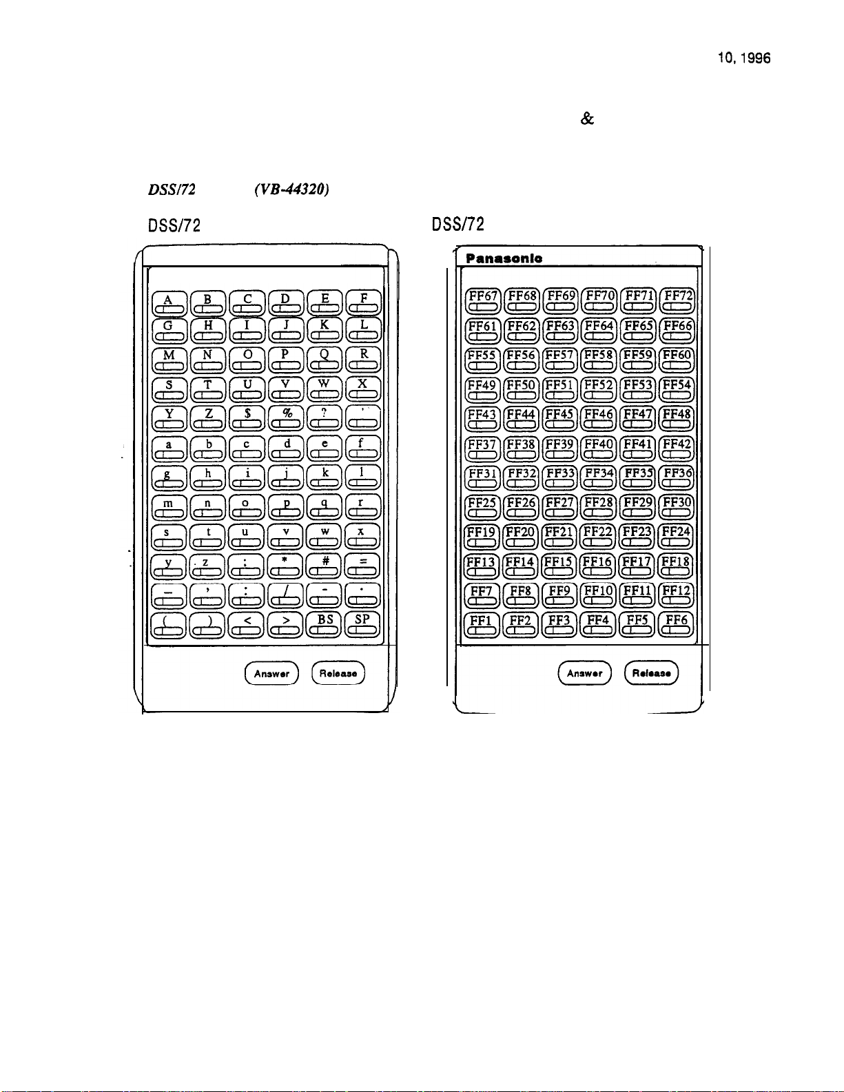
Key Arrangement
The keys on the new DSS/72 Console (VB-44320) are arranged differently from
the VB-43320 model. The new DSS console has 6 columns x 12 rows of keys (not
8 columns x 9 rows as in the previous version). This affects the following:
l
Name and Message Assignments (FF6 addresses).
arrangement of the keys is different.
l
FF-Keys.
The FF-keys on the DSS/72 console are numbered left-to-right,
bottom row first.
l
DSS #I Defaults.
The default extension number assignments on DSS
different.
The alphabetical
are
Technical Manuals Online! - http://www.tech-man.com
New Phone Features
l
Page 23
Page 23
DBS Release Notes
CPC-EX, Version
1 .O
(Preliminary)
Panasonic@
June
Figure 7.
Console
Key Layout (alphabetical)
Panasonlo
The new DSS key arrangement is shown in Figures 7
key layout
8.
Key Layout (FF-key numbering)
Page 24 l
44-Series New Phone Features
Technical Manuals Online! - http://www.tech-man.com
Page 24

Panasonic@
June
Figure 8.
Release Notes
CPC-EX, Version 1 .O (Preliminary)
DSS
Panasonio
Default Extension Numbers
Programming
The DSS/72 console (DSS
same manner as before:
Terminal Type:
where...
l
11 is the first DSS console for the first attendant
l
12 is the second DSS console for the first attendant
l
13 is the first DSS console for the second attendant
l
14 is the second DSS console for the second attendant
Technical Manuals Online! - http://www.tech-man.com
. . . DSS #4) is assigned to its extension number in the
FF3 (ExtPort)#
New Phone Features
l
Page 25
Page 25

DBS Release Notes
CPC-EX, Version 1 .O (Preliminary)
Panasonic@
June
The DSS/72 console’s FF-keys are assigned feature codes in the same manner
as
before (the only difference is the numbering arrangement of FF-keys l-72):
FF Key Assignments:
FF5 (DSSPort)# CONF (I-72)# (Code)#
The Name and Message Assignment addresses work the same way as before on
the DSS/72 console (the only difference is the placement of the keys when
entering the characters of the text):
Extension Name: FF6
SSD Name:
PSD Name:
FF6
FF6
Absence
Trunk Name:
FF6
Hunt Group Name: FF6
Reply: FF6
DID Name:
Name:
FF6
FF6
(ExtPort)# CONF (10 char.)#
(SSD)# CONF (16 char.)#
(PSD)# CONF (16 char.)#
CONF (15 char.)#
(Trunk)# CONF (6
(HuntGrp)# CONF (10 char.)#
CONF (15 char.)#
(6 char.)#
(6 char.)#
Note: If you use the 44-Series, DSS/72 for Name and Message assignment, you should use
the 44-Series phone for the attendant.
Operation
EM/24
Key Arrangement
Description
The
DSS/72 operates the same as previous models.
The keys on the new EM/24 unit (VB-44310) are arranged differently from the
VB-43310 model., The new EM/24 unit has 2 columns x 12 rows of keys (not 3
columns x 8 rows as in the previous version). This affects the following:
l
first.
The new EM/24 key arrangement is shown in Figure 9.
Page 26
Technical Manuals Online! - http://www.tech-man.com
l
New Phone Features
Page 26

Panasonic@
June
Figure 9.
DBS Release Notes
CPC-EX, Version 1 .O (Preliminary)
Programming
The terminal type for the EM/24 is specified in the same manner
Terminal Type: FF3 (EM/24 ExtPort)#
The EM/24 unit is linked to its extension phone in the same manner as before:
EM/24 Port Assignment:
The EM/24’s FF-keys are assigned feature codes in the same manner as before (the
only difference is the numbering arrangement of FF-keys l-24):
FF Key Assignments:
Operation
Technical Manuals Online! - http://www.tech-man.com
The 44-Series EM/24 operates the same as previous models.
FF3 (EM/24 ExtPort)#
FF5 (ExtPort)#
New Phone Features
as
before:
(phone ExtPort)#
CONF
.
Page 27
Page 27

DBS Release Notes
CPC-EX, Version 1 .O (Preliminary)
Speed-Dial Enhancements
Panasonic@
June 10.1996
Description
Programming
The CPC-EX supports up to 500 SSD numbers (code range 000-499) for each
system, and up to 10 PSD numbers (code range 900-909) for each extension.
With CPC-EX, you can chain up to 4 SSD codes together within a fifth SSD
number. You can also chain up to 4 SSD or PSD codes together within a fifth PSD
number. You can include both speed-dial codes and regular dialed numbers into
the same speed-dial number.
The maximum length of any speed-dial number is still 16 digits.
Assigning
to assign a System Speed Dial number from programming mode...
3-Digit SSD Code
000 thru 499 = range for CPC-EX
from programming mode
0
Version 1 .O
(up to 16 digits)#
Valid Entries (using a DSS console):
o-9 (digits O-9)
CONF
or
C
AUTO
(to clear data)
BS
(to backspace)
(to forward-space)
(to insert a pause)
(to access trunk group)
(to insert an SSD code)
EXAMPLE: To chain together SSD code 000 (C9-Pause), SSD code 001
OOO## C9 P
10288
5551212 #
OOM AUTO 000
EXAMPLE: To program SSD code 350 to access trunk group 81, then
pause, then dial
Page 26
Technical Manuals Online! - http://www.tech-man.com
l Speed-Dial Enhancements
Page 28

Panasonic3
June
10.1996
DBS Release Notes
CPC-EX, Version
1 .O
(Preliminary)
11.
SSDs from the
phone
to assign a System Speed Dial number from the attendant phone...
1. Press ON/OFF.
2. Press PROG.
3. Press AUTO.
4.
Enter the SSD code (000-499).
5.
Enter the number to be dialed.
6. Press HOLD.
7. Press ON/OFF.
EXAMPLE: To chain together SSD code 000 (CPPause), SSD
1.
Program SSD code 000 to dial “C9-Pause”:
a.
Press ON/OFF, then PROG, then AUTO.
code
001
b. Enter 000.
c.
Press CONF (to access a trunk group), then 9.
d.
Press REDIAL (to specify a “pause”).
e. Press HOLD.
2.
Program SSD code 001 to dial “10288-Pause”.
a.
Press ON/OFF, then PROG, then AUTO.
b. Enter 001.
c. Enter 10288.
d.
Press REDIAL (to specify a “pause”).
e. Press HOLD.
3.
Program SSD code 002 to dial
a.
Press ON/OFF, then PROG, then AUTO.
12 12”.
b. Enter 002.
c. Enter 5551212.
d. Press HOLD.
4.
Program SSD code 003 to chain dial all digits in SSD 000,
SSD 001, and SSD 002.
a.
Press ON/OFF, then PROG, then AUTO.
b. Enter 003.
c.
Press AUTO, 000, then AUTO, 001, then AUTO, 002.
d. Press HOLD.
Technical Manuals Online! - http://www.tech-man.com
Speed-Dial Enhancements l Page 29
Page 29

Release Notes
CPC-EX, Version 1 .O (Preliminary)
Panasonic@
June
Figure 12.
to assign a Personal Speed Dial number from programming mode...
EXAMPLE: To chain-dial SSD code
PSD code 909 on extension port 033...
EXAMPLE: To program PSD code 906 on extension port 033 to access pooled
trunk group 81, then pause, then dial 555-l 212...
Assigning PSDs from programming mode
3-Digit PSD Code
Valid Entries (using a DSS console):
o-9
CONF
or
AUTO
and PSD codes 901-902 together into
AUTO 001 AUTO 901 AUTO
C 1 P
(up to 16 digits)#
(digits O-9)
(to clear data)
BS
(to backspace)
(to forward-space)
(to insert a pause)
C
(to access trunk group)
(to insert an SSD or
PSD code)
Figure 13. Assigning
to assign a Personal Speed Dial number from a key telephone...
1. Press
2. Press PROG.
3. Press AUTO.
4.
Enter the PSD code (90-99 or 900-909).
5.
Enter the number to be dialed.
6. Press HOLD.
7. Press
EXAMPLE: To chain together SSD code 000 (C9-Pause) and SSD code
002 (555-1212) within PSD
1.
Press ON/OFF, PROG, AUTO.
2. Enter 900.
3. Press AUTO, 000,
4. Press HOLD.
a key telephone
ON/OFF.
ON/OFF.
code
then
AUTO,
002.
l
Page 30
Technical Manuals Online! - http://www.tech-man.com
Speed-Dial Enhancements
Page 30

Panasonic@
June
DBS Release Notes
CPC-EX, Version 1 .O (Preliminary)
Notes
1) Chain-Dialing Limitations and Restrictions:
l
You cannot chain-dial any PSD.codes within an SSD number, because the
system would not be able to choose which extension to take the PSD code
from (the same PSD code might exist on multiple extensions).
l
You cannot “chain-within-a-chain”. For example:
-- SSD Code 001 = AUTO 002(will not dial
returns busy tone instead)
-- SSD Code 002 = AUTO 003(will dial out)
-- SSD Code 003 = 5551212(will dial out)
(the above restriction applies to PSD codes as well)
l
You cannot chain-dial PSD or SSD codes if they are both included in each
other’s speed-dial number. For example:
-- SSD Code 000 = AUTO
-- SSD Code 001 = AUTO
2) The progr
address for SSD Display Restriction (FFl
not dial out; returns busy tone instead)
not dial out; returns busy tone instead)
[0 or
affects SSD codes 400-499.
l
If disabled (i.e., set to “O”), the numbers assigned to SSD codes 400-499 will
display during dialing. The default is
l
If enabled (set to “l”), the numbers assigned to SSD codes 400-499 will not
display during dialing.
. .
Numbers associated with SSD codes 000-399 will always display during
dialing.
Technical Manuals Online! - http://www.tech-man.com
Speed-Dial Enhancements l
Page 31
Page 31

Release Notes
CPC-EX, Version 1 .O (Preliminary)
Additional Serial Port on CPC Card
Panasonic@
June
Description
The CPC-EX card contains an on-board serial
used for Bus Monitor/ Remote Maintenance. This serial port (labeled CN5) is
located just above the
This additional serial
maintenance, without having to disconnect the SMDR cabling from the backplane
serial port (Serial Port 1).
l
Serial Port 1 (the backplane port) and Serial Port 2 have separate controls for
baud rate, stop bit, parity, and data length
Installation
Serial Port 2 requires the CPC-EX Serial Port Adapter Cable (VB-43890). This
cable connects to Serial Port 2 via a
terminal via a DB25 connector.
Figure 14. CPC-EX Serial Port 2
port
(Serial Port 2) which can be
on the front of the card (see the illustration on
port
allows you to dial directly into the system for remote
connector, and to a programming
page
8).
Master Cabinet
Serial Port Adaoter Cable End
(Requires
I
Male)
Pin No. and Connection
I
l
The standard DBS
to the programming terminal.
Page 32
Technical Manuals Online! - http://www.tech-man.com
l
Additional Serial Port on CPC Card
I
1
I I
I
5
4
7
Terminal End
or
Male)
CD
I
CTS
(Requires
In
cable (normally connected to CN6) may be
I
Page 32

Panasonic@
June
Release Notes
CPC-EX, Version 1 .O (Preliminary)
Programming
The following new addresses apply to CPC-EX Serial Port 2. (The addresses that
control the SMDR port remain at
to
program the DBS to perform
to specify
above address)...
Parity Count
thru
Parity Check
for Serial Port 2 (if Parity Check is ON in the
(0 or
on Serial Port
O=Parity check OFF
check ON
O=Odd
l=Even parity count
count,
1
to specify
to
specify
Baud Rate
for Serial Port
Stop Bit Length
for Serial Port
bits per second (bps)
bps
bps
bps
bit
bits
Technical Manuals Online! - http://www.tech-man.com
Additional Serial Port on CPC Card
l
Page 33
Page 33

DBS Release Notes
CPC-EX, Version 1 .O (Preliminary)
Panasonic@
June 10, 1996
Notes
to specify
Data Length
for Serial Port
(3 or
bits
l
Serial Port 2 requires a special interface cable.
l
Serial Port 2 can be used for Bus Monitor/Maintenance only. You must
continue to use the backplane port (Serial Port 1) for SMDR.
l
Port selections are made from the Attendant phone as follows:
dial
dial
dial
to set Serial Port I for...
Bus Monitor/Maintenance
SMDR
and Serial Port 2 for...
no output
Bus Monitor/Maintenance
no output
l
When Serial Port 2 is used(i.e.,
cannot be accessed.
has been entered), the internal RAI modem
Page 34
. Additional Serial Port on CPC Card
Technical Manuals Online! - http://www.tech-man.com
Page 34

Panasonic@
June
Networking
DBS Release Notes
CPC-EX, Version 1 .O (Preliminary)
NOTE:
The following inform&on covers Tl Networking features that directly affect CPC-EX
operation. For detailed information regarding
Reference Guide”, Part
Section 540.
Networking, see
Networking
CPC-EX allows up to 4 DBS’s to be connected together via Tl interface to form a DBS phone
network. Such a network provides the following new features:
Network Extension to Extension Calling
l
Call Forwarding to Network Extensions
.
Paging across Network nodes
l
Network Route selection
l
Remote DBS CO Access
l
SMDR Network Support
l
Independent Node Attendant Assignment
l
These feature are described in greater detail in the following sections.
Hardware Requirements
Each site (node) must contain the following hardware:
l CPC-EX
l SCC-B
l
l
l
Synch Unit
External CSU (not provided by Panasonic)
l
The maximum number of nodes which can be connected together is 4. Each node can be either a
single or double DBS cabinet configuration. The connection between these systems is accomplished
via
talk paths, with the quantity determined during installation.
Network Extension to Extension Calling
Networked DBS’s use a 4-digit extension numbering plan. The first digit determines the node being
called. For example:
Node 1
Node 2
leading digit 1
leading digit 2
Technical Manuals Online! - http://www.tech-man.com
Networking l
Page
Page 35

Release
CPC-EX, Version 1 .O (Preliminary)
Notes Panasonic@
June
Node 3
Node 4
Figure 15. Tl Network Extension Numbering.
leading digit 3
leading digit 4
Node 1
Extension
Node Network Trunks
Node 2
Extension 2XXX
When an extension in one node is called via the intercom from an extension in a different node, the
called extension rings
Intercom Voice Calling and OHVA do not work when calling from one node
to another.
The DBS determines how to route the calls based on the network trunk group priorities established
during programming. To allow optimum flexibility in a 4-node network, up to 3 different trunk
group priorities can be established.
Figure 16.
Network Call Priority Routing
Node 2
Node
1
Extension
Node 3
Extension 3XXX
Leading Digit
Priority 1.
2
.
Extension 2XXX
Node 4
Extension 4XXX
Call Forwarding to Network Extensions
Any call can forward to an extension on any node by assigning the targeted extension number in a
Personal Speed Dial bin. To establish the call forward setting, the user follows normal call
forwarding settings and uses the (AUTO)XXX personal speed dial number entry.
.
l
Page 36
Technical Manuals Online! - http://www.tech-man.com
Networking
Page 36

Panasonic@
June
CPC-EX, Version
DBS Release Notes
.O (Preliminary)
Paging Across Nefwork Nodes
Every node can allow or deny network paging for each class of service.
Network Route Selection
A’new option is available for Forced Least Cost Routing to include network route selection. This
option provides 50 6-digit entries which determine how dialed numbers are routed through the
network for optimal cost performance.
For example, if Node 1 of a networked system is in the 20 1 area code and Node 2 is in the 2 12 area
code, all calls from Node 1 to the 212 area code or surrounding area codes can be routed through the
second node to the public network.
Remote CO Access
End users in one node can also place calls manually through a distant node by dialing the node
number followed by a trunk group (9).
Network Support
New options are available in CPC-EX to support call accounting in networked systems.These
options are:
Specifying the call record to be printed. A new field has been added:
6#
In the actual SMDR record output, network traffic will be indicated by the following new record
types:
W = CO Outgoing to Network
w = CO Incoming from Network
= Network Transfer
t
The following new data output is found in the extension number field:
Incoming, Outgoing, Network
Network trunk number
Technical Manuals Online! - http://www.tech-man.com
Networking l
Page 37
Page 37

Release Notes
CPC-EX, Version 1 .O (Preliminary)
Panasonic@
June
Independent Node Attendant Assignment
A central network operator can be assigned for Dial 0 access from any node. Each node can
independantly designate a network attendant. For example, Nodes 3 can send Dial 0 calls to
the attendant on Node 1, while Node 4 sends Dial 0 calls to its local attendant.
Settings Modified for Networking
The following programming addresses have been modified to add parameters necessary for
networking. (See
Extension Number Digits
the
Networking Reference Manual
for
complete instructions)
Description
Programming
The CPC-EX card allows a 4-digit extension numbering plan to be used on
networked DBS systems. The first digit of the extension determines on which
DBS the extension is located
while extension 2547 will be on DBS 2. Each DBS routes calls based on the
leading digit of the dialed extension.
A DBS operating in a network environment must use the 4-digit extension
numbering plan. Stand-alone (non-networked) DBS systems, however, must
continue to use 2 or 3 digit extensions.
to specify the length of extension numbers...
for example, extension 1321 will be on DBS 1,
2=4-digit numbering
numbering
numbering
Note: An extra
must be entered to
confii the selection.
(or press
to cancel)
l
Technical Manuals Online! - http://www.tech-man.com
Page 38
Networking
Page 38

Panasonic@
June
Release Notes
CPC-EX, Version 1 .O (Preliminary)
SMDR Printing Mode
Description
Programming
SMDR data sent to Serial Port 1 can now include Network Calls also.
to specify the call type to be included in SMDR...
Trunk Type
Description
The setting for
Outbound and Inbound
(0
O=Include outbound calls only
Trunk Type now includes a parameter for E&M Network.
Programming
to determine the type of trunk signaling for each
new-W
(I-54)
Trunk Number (l-64)
start
Network
channel...
Technical Manuals Online! - http://www.tech-man.com
Networking l
Page 39
Page 39

DBS Release Notes
CPC-EX, Version 1 .O (Preliminary)
Extension Numbers
June 10.1996
Description
Programming
Forced
The address for extension number assignments has been modified to allow for
4-digit extensions.
to assign extension numbers to ports...
FF3 (l-l
Extension Port Extension Number
(1
Defaults: Port l=lO, 100, or 1000
Note:
Port
Port
etc.
N=DBS network node number l-4
or 1001
or 1002
Description
Programming
The address for Forced Least Cost Routing has been modified to include Network
Node Route Selection
to set individual extensions for forced
FF3 (1-I
Extension Port
Note: If not in a network
then only forced LCR is enabled.
(no forced
l=Enabled (forced
is not enabled),
l
Page 40
Technical Manuals Online! - http://www.tech-man.com
Networking
Page 40

Panasonic@
June
CPC-EX, Version 1 .O (Preliminary)
Other Changes to Programming Addresses
Flexible Function Screen Soft-Key Assignments (FFl
Key Assignments have been modified to allow up to S-digit entries.
(I-lO)#
and FF
New Programming Addresses
New programming addresses have been added to support
applicable only in a networked environment and can be ignored in a stand-alone (non-networked
DBS). Refer to the Tl Networking Reference Guide for detailed information.
Networking. These new addresses are
Technical Manuals Online! - http://www.tech-man.com
Networking l
Page 41
Page 41

DBS Release Notes
CPC-EX, Version 1 .O (Preliminary)
Panasonic@
June
Modification to Toll Restriction Service
Description
Programming
Table
IF EQUAL ACCESS CODE FORMAT IS:
0
Old Format
Setting
0
Action
Restrict
The program address for TRS Operator Access lS#...) has been modified
to allow an extension to dial “O+NXX” phone numbers, even if “O-only” dialing is
denied.
Four settings are possible. See Table 5 for descriptions.
FF7
ONLY)
Type of Call
“O-only” and “00-only” calls.
calls.
(l-l
Extension Port
IF EQUAL ACCESS CODE FORMAT IS:
Setting
0
(default)
See Table 5
New Format (1OlXXXX ONLY)
Action
Restrict
“O-only” and “00-only” calls.
Type of
calls.
additional digits per TRS tables.
additional digits per TRS tables.
additional digits per TRS tables,
Overseas Access Switch, and
tional Calls Switch.
+ additional digits per TRS
tables.
+ additional digits per
TRS tables, Overseas Access Switch,
and International Calls Switch.
continued...
Allow/Deny
+ additional digits per TRS tables.
+ additional digits per TRS tables
+ additional digits per TRS tables,
Overseas Access Switch, and International Calls Switch.
+ additional digits per
TRS tables.
+ additional digits per
TRS tables, Overseas Access Switch,
and International Calls Switch.
Page 42
l
Modification to Toll Restriction Service
Technical Manuals Online! - http://www.tech-man.com
Page 42

Panasonic@
June
CPC-EX, Version
DBS Release Notes
1 .O
(Preliminary)
IF EQUAL ACCESS CODE FORMAT IS:
0
Setting
1
2
Old Format
Action
Allow
Allow/Deny
Restrict “O-only” and “OO-only” calls.
Allow
Allow/Deny “01” + additional digits per Overseas
“O-only” and “OO-only” only calls.
+ additional digits per TRS tables.
Overseas Access Switch, and Intema- Overseas Access Switch, and International Calls Switch.
and International Calls Switch.
+ additional digits.
+ additional digits.
“IOXXXO”
Access Switch and International
Switch.
Overseas Access Switch and
tional Calls Switch.
ONLY) 1
Type of Call
calls.
+ additional digits per
additional digits.
+ additional digits per
IF EQUAL ACCESS CODE FORMAT
New Format (1OlXXXX ONLY)
Setting
2
Action
Allow
Allow/Deny
Restrict “O-only” and “00-only” calls.
Allow “0”
Allow/Deny
“O-only” and
+ additional digits per TRS tables.
tional Calls Switch.
TRS tables.
and International Calls Switch.
+ additional digits.
Access Switch and International Calls
Switch.
Overseas Access Switch and International Calls Switch.
Type of Call
additional digits.
+ additional digits.
+ additional digits per Overseas
calls.
calls.
additional digits per
additional digits per
calls.
additional digits per
3
Allow
Allow/Deny
“O-only” and “OO-only” calls.
calls.
“0” + additional digits.
additional digits.
+ additional digits.
+ additional digits
Access Switch and International Calls
Switch.
+ additional digits per
Overseas Access Switch and Intemational Calls Switch.
Overseas
3
Modification to
Allow
Allow/Deny “01” + additional digits per Overseas
“O-only” and
additional digits.
+ additional digits.
Access Switch and International Calls
Switch.
Overseas Access Switch and
tional Calls Switch.
Restriction Service l
calls.
calls.
+ additional digits per
Page 43
Technical Manuals Online! - http://www.tech-man.com
Page 43

Release Notes
CPC-EX, Version 1 .O (Preliminary)
Notes
l
The Operator Access address applies only to DBS systems using the new
(1995) NANP dialing plan (FF7
and 1 do not allow outbound dialing; TRS type 7 allows all dialing).
l
If “O-only”, “00-only”,
restricted (settings 0 or
disconnecting the call. However, if the user dials additional digits within 6
seconds, the DBS will check other switches to determine whether to allow or
deny the call.
l
For all settings
switch (FF7
preferred inter-exchange carrier.
l
For all settings
l
For settings 2 and 3, the system will not consider TRS settings for the trunk.
and FF7
Panasonic@
June
and to TRS types 2-6
or
calls are
the system will wait 6 seconds before automatically
the system will check the Equal Access Code Format
if a CIC (carrier identification code) is dialed to reach a
the system will check the international calls switches (FF7
if “01
or
is dialed.
types 0
l
Page 44
Modification to Toll Restriction Service
Technical Manuals Online! - http://www.tech-man.com
Page 44

Panasonic@
June
CPC-EX, Version 1
Maximum Time Priority Route Tables
Release Notes
(Preliminary)
Description
CPC-EX allows a maximum of 8 Time Priority Route Tables to be used during
LCR programming.
allows a maximum of 16 Time Priority Route
Tables. This number is reduced with CPC-EX since very few systems require
more than 3 of these tables and the saved memory space will allow for a planned
future enhancement.)
The DBS uses Time Priority Route Tables to route calls to the least expensive
carrier based on the time of day the call is placed. The following program
addresses use Time Priority Route Tables:
l FF8
l
FF8
l
FF8
l
Area Codes
Office Codes
LCR Office Code Tables
Priority Route Tables
Technical Manuals Online! - http://www.tech-man.com
Maximum Time Priority Route Tables
l
Page 45
Page 45

Release Notes
CPC-EX, Version
.O (Preliminary)
Panasonic@
June
.
Description
Support
CPC-EX
Interface). This ISDN Interface provides 23 voice channels (“B” channels) and a
control channel
One program address, for Trunk Circuit Type (FF2 (trunk
modified to allow for ISDN. This modification is described below. In addition,
CPC-EX provides several new programming addresses to
program addresses, as well as additional detail on ISDN, are described in the lSDN
Reference Manual, Part No.
Hardware Requirements
The following are the minimum hardware requirements for ISDN support in the DBS:
l
ISDN Trunk Card (VB-43571)
l CPC-EX (VB-43415)
. SCC-B (VB-43421) (with RGM 1.3 or later)
supports
(Integrated Services Digital Network -- Primary Rate
channel) over a 4-wire circuit.
Section 530.
21#
support
has been
ISDN. The new
l MDF Card (VB-43562)
l
l
Unit
External CSU (not provided by Panasonic)
Setting Modified for
Programming
to specify the Trunk Circuit Type...
FF2
Trunk Number
start
1 =Ground start
Page 46
Technical Manuals Online! - http://www.tech-man.com
.
Support
Page 46

Panasonic@
June
Modifications to SMDR
DBS Release Notes
CPC-EX, Version 1 .O (Preliminary)
Description
Station Message Detail Recording (SMDR) provides detailed call records of
outgoing calls. SMDR records can be output to a printer or an external call
accounting system. Additional call record types have been added to the SMDR
feature to support network calls and ISDN calls.
Figure 17 shows the SMDR format for CPC-EX. New values added for CPC-EX
are shaded.
Figure 17. SMDR Format for CPC-EX
1 2
01234567890123456789012345678901234567890~234567890~2345678901234567890~234567
12
type
3 4 5
DISA
3
DDDDDDDDDDDDDDDDDDDDDDDDDDDD
4 5
6
10-69,
CO number=DISA
(See Note
6
7 8
number (or network trunk)
digits,
O-9 or symbols l or#
2)
7
VWW
9
COS code
COS codes
start time
duration
1. Transferred calls include direct and group call pickups and conference calls.
If a station call is transferred to an outside number, an
also created for the station that is transferred.
2. The
l
appears
not appear
"Private"
with long distance calls that do not provide Caller ID information.
appears
as
a less-than sign
as
dialed digits.
appears with calls
a greater-than sign
on the
Centrex and
If the Caller ID Feature is installed and enabled,
that
have restricted Caller ID display and
PBX
codes, as well
record is
as
the
symbol
of Area"
Modifications to SMDR
l
Page 47
Technical Manuals Online! - http://www.tech-man.com
Page 47

Release Notes
CPC-EX, Version 1 .O (Preliminary) June
Setting Modified for SMDR
Values have been redefined for the SMDR Start Timer. The following table shows the new values.
Note: These new values apply to CPC-EX only.
Programming
to specify the SMDR Display Start Timer for CO Calls...
(O-1
0 =
4sec
1=6
2=8
3=10
4=12
5=14
6 =
8 =
9 =
10 =
16
20
25
30
Related Programming
l
(System): SMDR Print
l
(System): Parity Check
l
(System): Odd/Even Parity
l
(System): Baud Rate
l
(System): Stop Bit Length
l
(System):
l
l
l
l
l
l
(System): Serial Port Flow Control (X On/ X Off)
(System): SMDR Display Start Timer for CO Calls
(System): SMDR Printing Mode 1: Outbound, Inbound, Network
(System): SMDR Printing Mode 2: Long Distance and Local Calls
(System): SMDR Printing Mode 3: Header Title
FF3 (Extension) Station Message Detail Recorder (SMDR) Report
Length
l
Page 48
Modifications to SMDR
Technical Manuals Online! - http://www.tech-man.com
Page 48

Panasonic@
June
Hardware Requirements
l
A printer or external call accounting system is required to receive SMDR data.
Considerations
l
Unlike other CPC circuit cards, the CPC-EX supports two serial ports. Serial Port
1 is labeled CN4 and is located on the backplane. Serial Port 2 is labeled
is located on the front of the CPC-EX card. Serial Port 2 requires a special
interface cable.
.
Be sure to select the correct port to output SMDR data. From the Attendant’s
phone:
DBS Release Notes
CPC-EX, Version 1 .O (Preliminary)
and
dial
to set Serial Port 1 (the backplane port) to output Bus
Monitor/Maintenance and Serial Port 2 to no output.
dial
to set Serial Port 1 to output SMDR and Serial Port 2 to output
Bus Monitor/Maintenance data.
to set Serial Port 1 to output SMDR data and Serial Port 2 to
no output.
Technical Manuals Online! - http://www.tech-man.com
Modifications to SMDR
l
Page 49
Page 49

DES Release
CPC-EX, Version 1 .O (Preliminary)
Notes
June
Modification to
Description
The default values for
changed to set “Wink Start” as the default. This will allow easier programming of
E&M trunks.
Signaling Types
Outgoing Signaling Type
Programming
Incoming Signaling Type
Incoming and Outgoing Signal Types have been
Trunk Number (l-64)
O=Immediate Start
l=Wink Start
Tone Start
‘Programming
Trunk Number (l-64)
(0 or
O=Immediate
l=Wink
Start
I
Page 50
Technical Manuals Online! - http://www.tech-man.com
. Modification to Tl Signaling Types
 Loading...