

Panasonic VBHN325SA17, VBHN330SA17 installation
VBHNxxxSA17 series
General Installation Manual
Photovoltaic Module HIT®
VBHNxxxSA17 series
Thank you for choosing Panasonic HIT®.
Please read this manual completely
before installation or use of Panasonic
PV(photovoltaic) modules. With proper
operation and maintenance, Panasonic
HIT® will provide you with clean,
renewable solar electricity for many
years. This manual contains important
installation, maintenance and safety
information. The word “module” as
used in this manual refers to one or
more PV modules. Retain this manual
for future reference. The module is
considered to be in compliance with UL
1703 only when the module is mounted
in the manner specified by the
mounting instructions below.
SANYO is part of the Panasonic Group
and is in charge of the manufacturing
process for Panasonic HIT®.
Model No.
VBHN325SA17
VBHN330SA17
Contents
Please read before installation
Safety Precautions
General Information :3
Warning :3
Cautions :3
General Safety :3
UL Listing Information :3
Installation
General :4
Notes on Installation :4
Operating Conditions :5
Special Conditions :5
Specifications
Note on Specifications :6
Mechanical Loading :6
Unpacking and handling :6
Wiring
General :6
Module Wiring :6
Array Wiring :7
Earth Ground Wiring :7
Grounding Locations :7
Grounding Methods :7
Module Terminations :8
Junction Box and Terminals :8
Conduit :8
Diodes :8
Maintenance :9
Disclaimer of Liability :9
Contact Information :9
“HIT” is a registered trademark of
Panasonic Group.
Other product and service names listed
in this manual are trademarks or
registered trademarks of their
respective companies.
1

Edition
Revision
Date
Revised Item
Revised Content
New Edition
2017.11.15
2
Safety Precautions
General Information
The installation of solar modules
requires a great degree of skill and
should only be performed by qualified
licensed professionals, including,
without limitation, licensed contractors
and electricians.
WARNING
All instructions should be read and
understood before attempting to
install, wire, operate, and maintain a
photovoltaic module.
Contact with electrically active parts
of the module such as terminals can
result in burns, sparks, and lethal
shock whether the module is
connected or disconnected.
The installer assumes the risk of all
injury that might occur during
installation, including, without
limitation, the risk of electric shock.
The modules generate DC (direct
current) electrical energy when
exposed to sunlight or other light
sources. Even a single module
produces enough voltage and
current, to cause shocks and burns if
safety precautions are not followed.
The shock hazard increases as
modules are connected in parallel,
producing higher current, and as
modules are connected in series,
producing higher voltages.
Do not hit the back sheet of a
module by the connector or other
things.
To avoid the hazard of electric
sparks, shock, fire, burns, damage
and injury, work only in dry
conditions, with dry modules and
dry tools.
In order to avoid submerging cables
and connectors in the water, cables
must be fixed either to the module
frame using cable fixing holes or to
the mounting structure.
Do not stand or step on modules. Do
not puncture, cut, scratch or
damage the backsheet of a module.
Backsheet damage will void a
module’s Limited Warranty and may
cause fire. Never use modules with a
damaged back sheet.
Do not allow children and
unauthorized persons near the
installation or storage site of
modules.
Completely ground all modules.
Do not disassemble a module,
attempt any repair, open the
junction box cover, nor remove any
parts installed by Panasonic. There
are no user serviceable parts within
the module or junction box.
Unauthorized persons - except the
qualified licensed professional should not perform any electrical
work, including wiring.
Wear suitable clothing, guards, eye
protection and gloves to prevent
you from direct contact with 30 VDC
or greater.
Wear non-slip gloves and carry
modules by the frame using both
hands. Do not attempt to carry a
module by yourself.
Do not carry a module by its wires or
junction box.
Do not drop anything on the surface
of a module.
Ensure all system components are
compatible, and they do not subject
the module to mechanical or
electrical hazards.
Sparks may occur; do not install
modules where flammable gases or
vapors are present.
Never rest or leave a module
unsupported or unsecured.
Do not drop modules.
Do not use or install broken modules.
Do not artificially concentrate
sunlight on a module.
Do not touch the junction box
terminals.
Do not change the wiring of bypass
diodes.
Do not touch a module unnecessarily.
The glass surface and frames get hot.
There is a risk of burn.
CAUTIONS
Use a module for its intended
purpose only.
Do not treat the back sheet, frame,
or front surface with paint or
adhesives, to avoid reducing its’
functionality, damage, and causing
inoperable conditions, and other
unknown troubles.
Do not insert PV cable between back
side and mounting structure rail.
GENERAL SAFETY
Follow all permissions, installation
and inspection requirements.
3
Before installing modules, contact
the appropriate authorities having
jurisdiction to determine permissions,
installation and inspection
requirements, which should be
followed.
Electrically ground modules for all
systems of any voltage. If not
otherwise specified, it is
recommended that requirements of
the latest National Electrical Code
(USA) or Canadian Electric Code
(Canada) or other national or
international electrical standards be
followed. Refer to “Earth Ground
Wiring” section for more
information.
Be sure that the building or structure
(roof, façade, etc.) where the
modules are being installed has
enough strength to support the load
of the modules.
For modules mounted on roofs,
special structures may be required to
help provide proper installation
support.
The fire rating of this module is valid
only when mounted in the manner
specified in the mechanical
mounting instructions.
Both, roof construction and module
installation design have an effect on
the fire resistance of a building.
Improper installation may contribute
to fire hazards.
The models in this instructions are
suitable to maintain the System Fire
Class Rating A when used with a
Listed mounting system and a roof
covering that have been rated as a
Class A System when installed on a
steep slope roof and/or a low slope
roof with "Type 2" modules.
Additional devices such as ground
fault, fuses, and disconnects may be
required.
Do not use modules of different
specifications in the same system.
Follow all safety precautions of
other system components which are
used.
UL Listing Information
To satisfy UL requirements, when
installing the modules, be sure to:
1) Use only stranded or solid copper
single–conductor sunlight-resistant
cable rated for outdoor use (e.g.
type UF or USE) , for all wiring that is
exposed to weather.

2) Observe the requirements described
in sections labeled INSTALLATION
and SPECIFICATIONS.
INSTALLATION
General
Please read this guide completely
before installing or using your
Panasonic PV modules. This section
contains important electrical and
mechanical specifications.
Modules should be firmly fixed in
place in a manner suitable to
withstand all expected loads,
including wind and snow loads.
Metals used in locations that are
exposed to moisture shall not be
employed alone or in combinations
that could result in deterioration or
corrosion.
Install modules where they are not
shaded by obstacles like buildings
and trees. Pay special attention to
avoid partially shading the modules
by objects during the daytime.
If needed, contact an Authorized
Representative with questions
regarding mounting profiles for
Panasonic HIT®.
Notes on Installation
Clearance between the roof surface
and module frame is required to
allow cooling air to circulate around
the back of the module. This also
allows any condensation or moisture
to dissipate. The required clearance
between the roof surface and the
module is more than 4 inch.
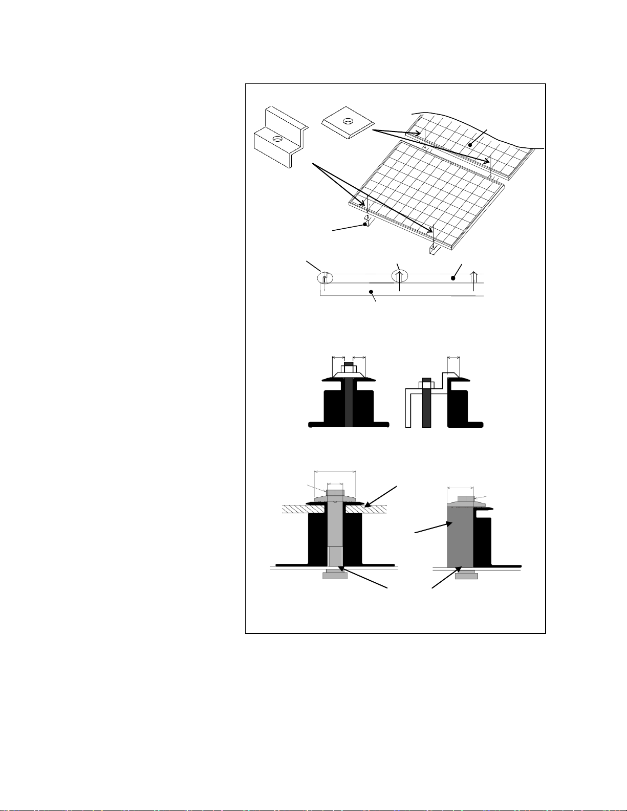
Panasonic recommends the
installation method and mounting
profile shown in Figure 1-1 and
Figure 1-2.
Figure 1-1 shows that a module
should be attached on a mount or
support structure rail by corrosiveresistant metal clamps.
The clamps should be made of
aluminum alloy or other material
that will reasonably protect against
a risk of electrolytic corrosion.
Figure 1-2 shows using a bolt and
nut for mounting.
Recommendation of bolt torque: 10
ft-lbs.
The module was tested using
IronRidge clamps with the
specifications see figure 1-1 and
below;
4
Universal
Fastening
Objects
7/16”
Head
0.37”
1.12”
Modul
Stopper
Sleeves
0.73”
7/16”
Head
End Clamp
(2 places)
Mid Clamp
(2 places)
Solar Module
Mounting
Structure Rail
Solar Module
Mid Clamp
End Clamp
Mounting Structure Rail
<Cross section of clamps>
Overlap range ≧ 0.24” (6mm)
Mid clamp
End clamp
Mid clamp
End clamp
<Ironridge clamps>
Figure 1-1. Installation
Installation (reference)
IronRidge clamps:
Provider: IronRidge Inc.
Product Line: RoofMount
Clamps type: Top Mounting
Clamps (Universal Fastening
Objects(UFOs) and Stopper
Sleeves)
IronRidge Part No. UFO-CL-001,
UFO-CL-001B, UFO-STP-40MM,
UFO-STP-40MM-B
Width: Universal Fastening
Objects; 1.12”(28.4 mm), Stopper
Sleeves; 1.09”(27.7 mm)
Thickness: Universal Fastening
Objects 0.29”(7.4mm),
Torque: 9.04 N.m (80 in-lbs).
Material: Universal Fastening
Objects; 300 Stainless steel,
Stopper Sleeves; 6000 Aluminum
alloys
Note: Please refer to IronRidge
manual, for installation method.
Panasonic does not provide a
warranty for clamps. The module
warranty Panasonic provides shall be
voided if clamps selected by the
customer are of an improper
material or size
Operating Conditions
Panasonic requires that modules are
operated within the following
Operating Conditions:
1) Terrestrial applications only-no outer
space or Special Conditions (see
below).
2) The operating temperature must be
within –40°C (-40 °F) to 85°C (185 °F).
3) The wind pressure load of the
installation site should be less than
Load Resistance shown in “Mount
Locations and Load Resistance”
table in Figure 2.
4) Some environmental conditions
could apply. Please refer to
Panasonic’s warranty exclusions.
Special Conditions
1) The operating temperature and
installation place are different from
the recommended Operating
Conditions.
2) Salt damage is severe at the
installation place.
3) Hail and snow damage is excessive
at the installation place.
4) Sand and dust damage is excessive
at the installation place.
5) Air pollution, chemically active
vapors, acid rain, and/or soot, etc.
5
 Loading...