

Panasonic U-96ME1U9E, U-96ME1U9, U-52LE1U6, U-36LE1U6, S-54MF1U6 Service Manual
...
INSTALLATION INSTRUCTIONS
Communication Adaptor
Model No. CZ-CFUNC1U
For your safety
Read the following instructions carefully, and carry out secure installation and electrical work.
■
The precautions given in this manual consist of specifi c “Warnings” and “Cautions”. They provide important safety-related information. Be
■
sure to strictly observe all safety procedures. The labels and their meanings are as described below.
Warning
Caution
* After installation is completed, perform a test run to check for operating trouble. Explain operating procedures to the customer following the
central control device Operating Instructions and then request the customer to store this Instructions for the Electrical Installer together with
the central control device Operating Instructions.
Be sure to arrange installation by the dealer where the system was purchased or by a professional installer. Electric shock or fi re may result
●
if an inexperienced person performs any installation or wiring procedures incorrectly.
Be sure that this unit is securely installed in accordance with this Instructions for the Electrical Installer. Electric shock or fi re may result if
●
any installation or wiring procedures are incorrectly performed.
Only a qualifi ed electrician should attempt to connect this system, in accordance with the instructions in this manual. Insuffi cient electrical
●
circuit capacity or incorrect installation may cause electric shock and fi re.
Use the specifi ed cables for the electrical connections, and connect the cables securely. Run and fasten the cables securely so that
●
external forces or pressure placed on the cables will not be transmitted to the connection terminals. Overheating or fi re may result if
connections or attachments are not secure.
Depending on the installation conditions and location, an earth leakage breaker may be required. If an earth-leakage breaker is not
●
installed, there is a danger of electric shock or fi re.
This symbol refers to a hazard or unsafe procedure or practice that can result in severe personal injury or
death.
This symbol refers to a hazard or unsafe procedure or practice that can result in personal injury or product or
property damage.
Warning
Caution
Ground yourself to discharge static electricity before performing any wiring.
●
Note:
This equipment has been tested and found to comply with the limits for a Class B digital device, pursuant to part 15 of the FCC Rules. These
limits are designed to provide reasonable protection against harmful interference in a residential installation. This equipment generates, uses
and can radiate radio frequency energy and, if not installed and used in accordance with the instructions, may cause harmful interference to
radio communications. However, there is no guarantee that interference will not occur in a particular installation. If this equipment does cause
harmful interference to radio or television reception, which can be determined by turning the equipment off and on, the user is encouraged to
try to correct the interference by one or more of the following measures:
• Reorient or relocate the receiving antenna.
• Increase the separation between the equipment and receiver.
• Connect the equipment into an outlet on a circuit different from that to which the receiver is connected.
• Consult the dealer or an experienced radio/TV technician for help.
FCC Caution: To assure continued compliance, follow the attached installation instructions. Any changes or modifi cations not expressly
approved by the party responsible for compliance could void the user’s authority to operate this equipment.
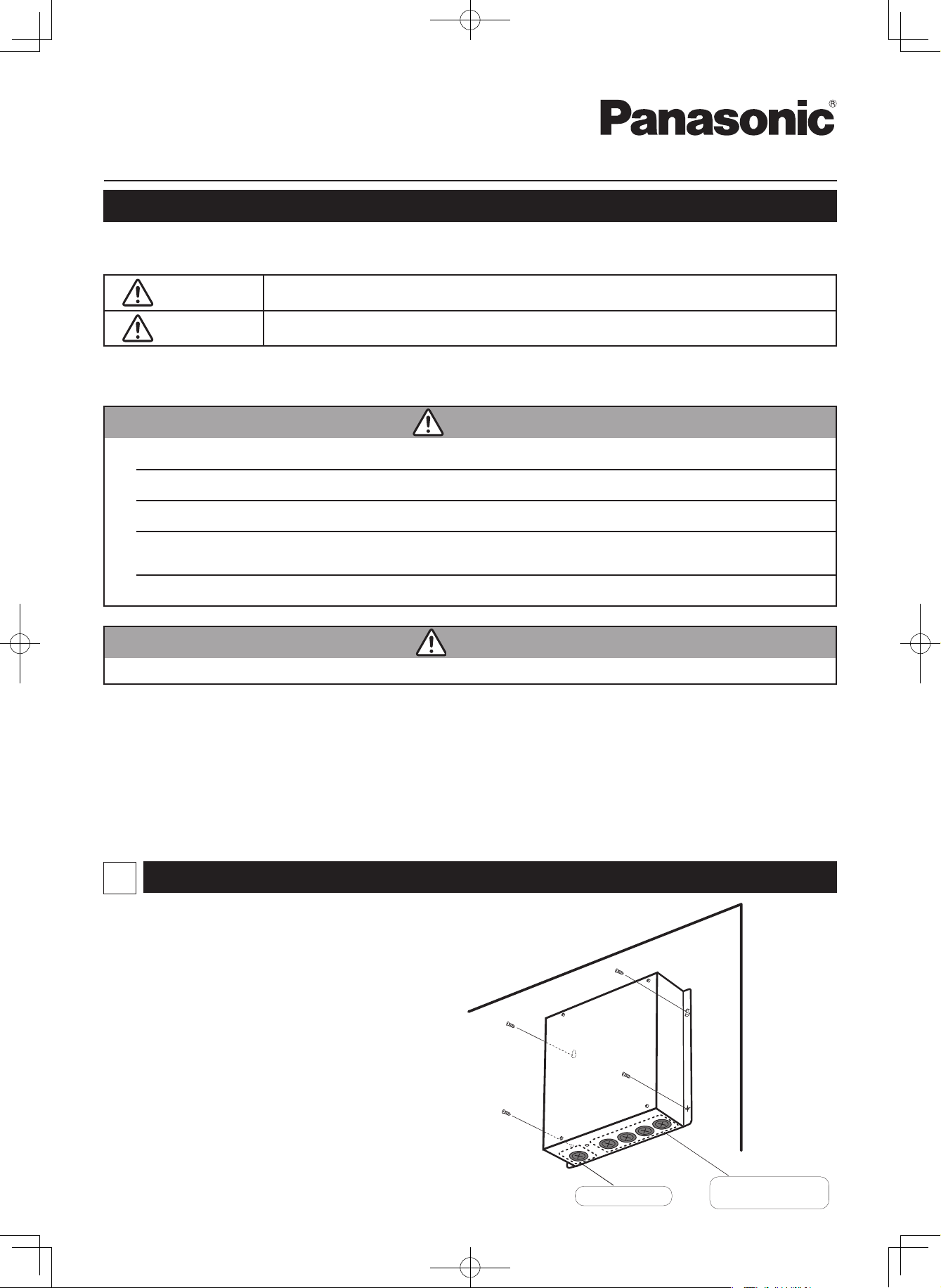
Installing
1
Note
Do not run the indoor/outdoor communication lines, input/
●
output lines, and power cables through the same conduit, or
twist those cables together, or place the cables near one
another. It can cause malfunction.
Install the main unit away from any sources of electrical
●
noise.
Avoid installing in any locations where the unit may come
●
into contact with water, or in any extremely humid locations.
Avoid installing in any location that is subject to excessive
●
vibration or physical impacts.
(1) After determining the attachment position, secure the
installation hardware as shown in the dimensions diagram. If
the included screws will not work for the installation, prepare
appropriate screws (such as metric ones) for use at the site.
(2) Attach the main unit and fasten the installation hardware as
illustrated.
(3) If the installation hardware is loose or appears like it will fall
out, remove the upper case on the unit and secure with
screws in the failsafe screw holes.
85464369525011
PanasonicCZ-CFUNC1UEng.indd1PanasonicCZ-CFUNC1UEng.indd1 2011/11/1112:03:532011/11/1112:03:53
1
Power supply line
Communication lines
Input/output lines
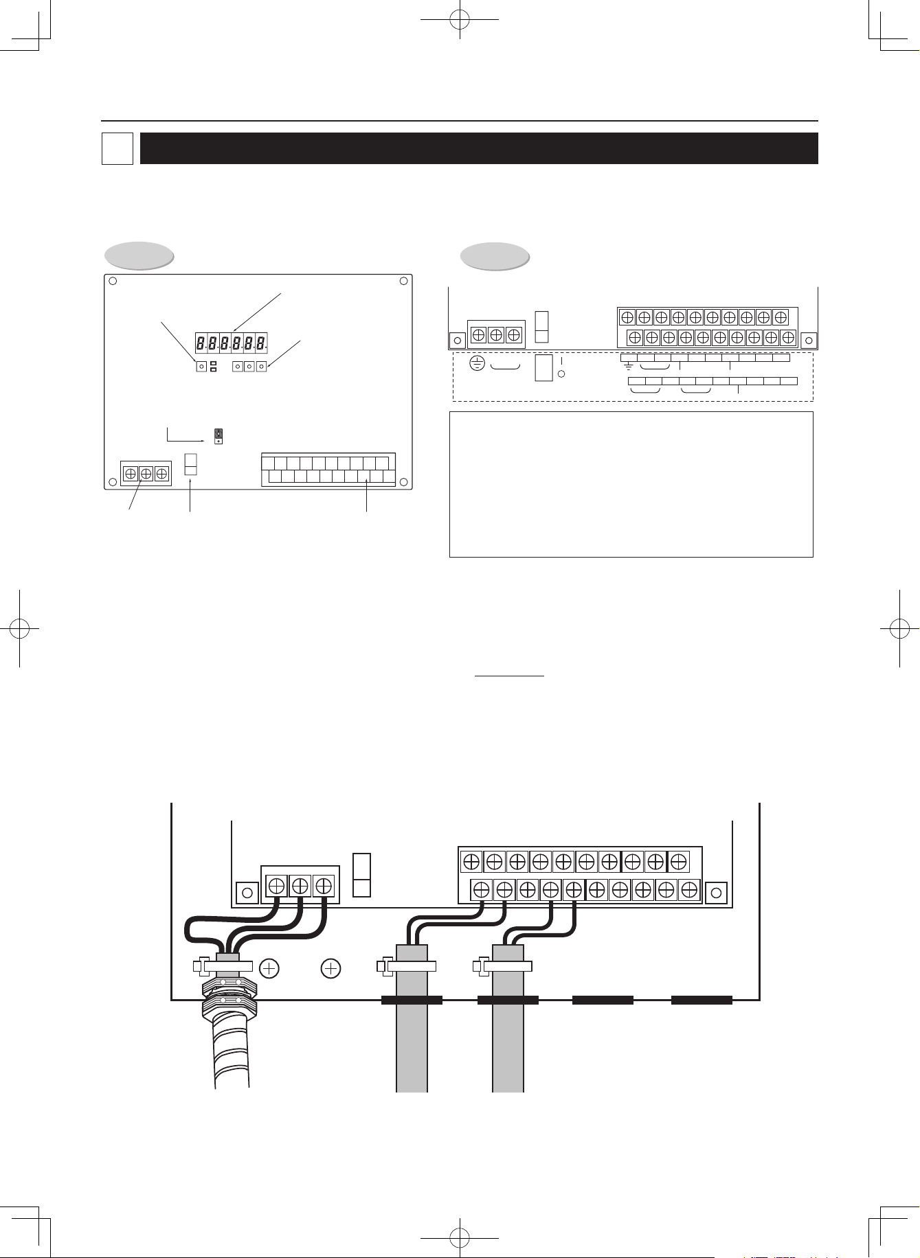
Wiring
2
Always shut off the power supply (breaker) before installing or uninstalling the Communication Adaptor.
Remove the two screws at the front of the unit and remove the upper case.
Arrangement of the terminal board and switches
Detailed board
illustration
Detailed terminal
assembly illustration
7-segment LED
Home key
Up, down and
set keys
S6 S9S8S7D1
HOME
Terminating resistance plug
for the Communication
Adaptor control wire
ADAPTER BOARD
S1
31
CN1
D2 UP
CN32
BA
DOWN
SET
N
L
100-240V
50/60Hz 1-PH
ON
OFF
POWER
ADAPT +/- : Communication Adaptor control wire (RS-485)
CN2
10
0
19
9
LINK 1/2: Inter-unit control wiring (HBS)
P1: Pulse meter inputs (gas fl ow meter and fuel fl ow meter) (*)
P2 and P3: Pulse meter input (power fl ow meter) (*)
DI1: All stop input (*)
DI2: All operation input (*)
10 11 12 13 14 15 16 17 18 19
+–
ADAPT(RS485)DO-COMMON DI-COMMON
0 1 2 3 4 5 6 7 8 9
(
LINK1
–U2
LINK1
DI3: Reserved
Power supply
terminal strip
Power switch
Signal terminal strip
(see details at right)
DO1: All alarm output (*)
DO2: All operation output (*)
(*) Input/output function when connecting to the Intelligent Controller
(1) Connecting the power supply
The unit can use AC power sources between 100 and 240 V.
Connect the power supply to terminals 2 (N) and 3 (L) on the power terminal strip CN1. (Connect the AC neutral end to N.)
Connect the ground line securely.
DO 1 DO 2
U1 U2
(
LINK2
)
)
–U2
LINK2 P-COMMON
DI 1 DI 2 DI 3
3P2P1P2U1U
(2) Connecting the communication line
For the Communication Adaptor control wires, use only two-conductor shielded wire with a cross-section between AWG#20 and AWG#14
●
(MVVS or CPEVS).
Be sure to ground only one end of the shielding.
●
The overall length of each line should be 3280 ft. or less.
●
Do not run the communication line through the same conduit as the power supply, use the same cable as the power supply, or run close to
●
the power supply line (maintain at least 11-13/16 in. separation).
Do not run the LINK1 and LINK2 signal lines through the same conduit, use the same cable for wiring, or run them close together.
●
Use different communication and power cables so they can be differentiated visually.
●
Conduit(Power cables) Inter-unit control wiring
2
PanasonicCZ-CFUNC1UEng.indd2PanasonicCZ-CFUNC1UEng.indd2 2011/11/1112:03:532011/11/1112:03:53
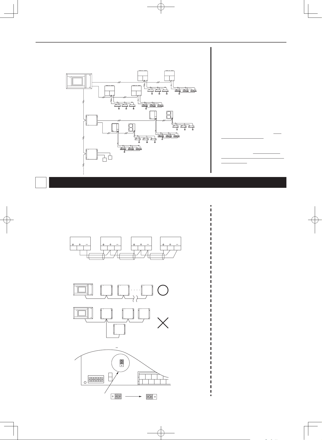
Basic wiring diagram
Wire up the Communication Adaptor control wire and Inter-unit control wiring as shown in the
fi gure below.
Intelligent controller
Inter-unit control wiring
(Example using an Intelligent Controller)
Outdoor unit
Wiring procedure
Inter-unit control wiring
●
Connect terminals 0 and 1 (LINK1)
on the Communication Adaptor signal
terminal strip CN2 to the inter-unit
control wiring terminals of the indoor
or outdoor unit. There is no polarity.
If connecting two inter-unit control
wiring systems, connect terminals 3
Communication
Adaptor control
wire
Indoor unit
Outdoor unit
Inter-unit control wiring
Outdoor unit
and 4 (LINK2) on CN2 in the same
manner.
Communication Adaptor control wire
●
Connect terminals 11 and 12 (ADAPT
+ and -) on the Communication
Adaptor signal line terminal strip
CN2 with the same terminals on the
other Communication Adaptor. The
Communication
Adaptor
W
G: Gas fl ow meter
G
Communication
Adaptor
Precautions for the Communication Adaptor control wire
3
W: Power fl ow meter
Indoor unit
terminals have polarity. Connect so
the positive and negative elements
are correct.
When connecting, be sure to use
crossover wiring, not a branching
confi guration.
(Some items are duplicated in other sections.)
(1) The overall length should be 3280 ft. or less.
(2) The communication wire has polarity. Connect so the positive and negative elements are
correct.
(3) Use only shielded wire. Be sure to ground only one end of the shielding.
Communication
Adaptor 1
ADAPT
(RS485)
10 11 12
(4) Be sure to use crossover wiring, not a branching confi guration.
* Connect the Intelligent Controller to the end of the crossover confi guration.
Intelligent
Controller
Intelligent
Controller
(5) Change the terminating resistance plug CN32 to the “B” side (with terminal resistance) on the
board for the Communication Adaptors (2 of them) at both ends of the confi guration.
Communication
Adaptor 2
ADAPT
(RS485)
10 11 12
Communication
Adaptor
Communication
Adaptor
S1
CN1
Communication
Adaptor 3
A
CN32
B
ADAPT
(RS485)
10 11 12
101112
Communication
Adaptor 4
0
123
ADAPT
(RS485)
10 11 12
13
(6) Do not hook more than 16 units up
to the Communication Adaptor. The
system you are using (such as an
Intelligent Controller) may have
further restrictions. Consult the
Installation Instructions for your
system.
* The Intelligent Controller has a
maximum restriction of seven
units.
(7) Make sure that high voltage AC
lines are not connected to the
Communication Adaptor control
wire or the inter-unit control wiring
terminals.
* If high voltage AC is accidentally
applied to the inter-unit control
wiring terminals, a fuse will blow to
protect the controller board.
If this happens, disconnect the AC
line, and connect the U2 terminal
wire of the inter-unit control wiring
to the spare terminal. (Do not
change the U1 terminal wire.)
Spare terminals are located right
next to U2.
Change terminal number 1 LINK1U2
to terminal number 2 (LINK1-
→
U2)
Change terminal number 4 LINK2U2
to terminal number 5 (LINK2-
→
U2)
Terminating resistance
plug for Communication
Adaptor control wire
BA BA
Terminating resistance
“off” (factory setting)
Terminating
resistance “on”
3
PanasonicCZ-CFUNC1UEng.indd3PanasonicCZ-CFUNC1UEng.indd3 2011/11/1112:03:532011/11/1112:03:53
 Loading...