

Panasonic U-5ML5DPQ, U-5ML5XPQ, U-4ML5DPQ, U-6ML5XPQ, U-6ML5DPQ Installation Manual
...
INSTALLATION MANUAL
URBAN MULTI AIR CONDITIONER
U-4ML5DPQ
U-5ML5DPQ
U-6ML5DPQ
U-4ML5XPQ
U-5ML5XPQ
U-6ML5XPQ
Installation manual
Urban Multi air conditioner
Installationsanleitung
Urban Multi Klimaanlage
Manuel d'installation
Unité extérieure Urban Multi
Montagehandleiding
Urban Multi airconditioner
Manual de instalación
Acondicionador de aire Urban Multi
Manuale d'installazione
Climatizzatore Urban Multi
∂Á¯ÂÈÚ›‰ÈÔ ÂÁηٿÛÙ·Û˘
KПИМ·ЩИЫЩИОfi Urban Multi
Manual de instalação
Ar condicionado Urban Multi
English
Deutsch
Français
Nederlands
Español
Italiano
EППЛУИО¿
Portugues
D2D2
L1
L2
B1
B2
D2D2
L1
L2
3
1
1
1
4
D2D2
D2
CC
L2
L2
AA
D2D2
D2
CC
L2
L2
AA
2
2
3
500
≥1
1
≥1000
≥1000
≥1000
6
≥1500
≥1500
4
5
≥1500
3
2
(mm)
2 3
B2
B2
EE
L1
L1
HH
B1B1B1
D1D1D1
B2B2B2
EE
L1
L1
HH
B1
B1
D1D1D1
L2>H
L2<H
L2>H
L2<H
≥100
≥150 ≥150
L2>H
L2<H
L1≤H
H<L1
L2≤H
H<L2
≥200 ≥1000
L2>H
L2<H
L1≤H
H<L1
L2≤H
H<L2
B
1
3
C
2
≥100
≥100
≥100
≤500
≥100
≥100
≥250
≤500
≥100
≥200
≥300≥200
≥300
≤500
≥300
≥250
≥300
≥300 ≤500
≥250
≥300
≥100
≥150
≥1000
L1≤H
L2≤H
L1≤H
L2≤H
A
2
≥500
≥500
≥500
≥500
≥750
≥1000
≥1000
≥1000
≥1000
≥1000
≥1500
≥1000
≥1250
≥1500
≤500 ≥1000
≤500
≥1000
≥1000
≥1000
≤500
≥1000
≤500
≥1000
≥1000
≥1000
≤500 ≥1000
0<L1≤1/2 H
1
/2 H<L1≤H
0<L2≤1/2 H
1
/2 H<L2≤H
0<L2≤1/2 H
1
/2 H<L2≤H
0<L1≤1/2 H
1
/2 H<L1≤H
0<L2≤1/2 H
1
/2 H<L2≤H
3
1
3
3
1+2
3
4
5
321
78
44
5 611
5
6
1
4
7
9
3
2
56
13
6
8
10
12
B
9
10
A
C
7
D
1111
1
7

U-4ML5DPQ U-4ML5XPQ
U-5ML5DPQ U-5ML5XPQ
U-6ML5DPQ U-6ML5XPQ
Urban Multi air conditioner
Installation manual
ONTENTS
C
1. Safety considerations.................................................................1
2. Introduction ................................................................................ 2
2.1. Combination ................................................................................... 2
2.2. Standard supplied accessories ......................................................2
2.3. Optional accessories...................................................................... 2
2.4. Technical and electrical specifications ........................................... 2
3. Before installation ......................................................................3
3.1. Precautions for R410A ................................................................... 3
3.2. Installation ...................................................................................... 3
3.3. Handling ......................................................................................... 3
4. Selecting installation site............................................................3
5. Precautions on installation.........................................................4
5.1. Installation method for prevention of falling over ............................ 4
5.2. Method for removing transportation stay ........................................ 4
5.3. Method for installing drain piping....................................................4
6. Installation servicing space........................................................5
7. Refrigerant pipe size and allowable pipe length.........................5
7.1. Selection of piping material............................................................ 6
8. Precautions on refrigerant piping...............................................6
8.1. Cautions for brazing ....................................................................... 6
8.2. Cautions for flare connection..........................................................6
9. Refrigerant piping.......................................................................7
9.1. Preventing foreign objects from entering........................................7
9.2. Cautions for handling stop valve .................................................... 7
9.3. How to use the stop valve .............................................................. 8
9.4. Cautions for handling the valve cover............................................. 8
9.5. Cautions for handling service port.................................................. 8
9.6. Precautions when connecting field piping and
regarding insulation........................................................................8
9.7. Leak test and vacuum drying .......................................................10
10. Additional refrigerant charge.................................................... 10
10.1. Important information regarding the refrigerant used...................10
10.2. 3 procedures for adding refrigerant..............................................11
11. Electrical wiring work ...............................................................13
11.1. Internal wiring – Parts table.......................................................... 13
11.2. Precautions on electrical wiring work ........................................... 14
11.3. Connection example of total system wiring..................................14
11.4. Connecting power wire and transmission wires ........................... 15
11.5. Power circuit and cable requirements .......................................... 15
12. Before operation ......................................................................17
12.1. Service precautions...................................................................... 17
12.2. Checks before initial start-up........................................................ 17
12.3. Field setting..................................................................................17
12.4. Test operation............................................................................... 19
12.5. Checks in normal operation.......................................................... 20
12.6. Temperature adjustment operation confirmation.......................... 20
13. Service mode operation...........................................................21
14. Caution for refrigerant leaks.....................................................21
14.1. Introduction................................................................................... 21
14.2. Maximum concentration level....................................................... 21
14.3. Procedure for checking maximum concentration ......................... 21
15. Disposal requirements ............................................................. 22
age
P
READ THESE INSTRUCTIONS CAREFULLY BEFORE
INSTALLATION. KEEP THIS MANUAL IN A HANDY
PLACE FOR FUTURE REFERENCE.
IMPROPER INSTALLATION OR ATTACHMENT OF
EQUIPMENT OR ACCESSORIES COULD RESULT IN
ELECTRIC SHOCK, SHORT-CIRCUIT, LEAKS, FIRE OR
OTHER DAMAGE TO THE EQUIPMENT. BE SURE ONLY
TO USE ACCESSORIES MADE BY PANASONIC WHICH
ARE SPECIFICALLY DESIGNED FOR USE WITH THE
EQUIPMENT AND HAVE THEM INSTALLED BY A
PROFESSIONAL.
PANASONIC EQUIPMENT IS DESIGNED FOR
COMFORT APPLICATIONS. FOR USE IN OTHER
APPLICATIONS, PLEASE CONTACT YOUR LOCAL
PANASONIC DEALER.
IF UNSURE OF INSTALLATION PROCEDURES OR USE,
ALWAYS CONTACT YOUR DEALER FOR ADVICE AND
INFORMATION.
THIS AIR CONDITIONER COMES UNDER THE TERM
"APPLIANCES NOT ACCESSIBLE TO THE GENERAL
PUBLIC".
1. S
AFETY CONSIDERATIONS
The precautions listed here are divided into the following two types.
Both cover very important topics, so be sure to follow them carefully.
WARNING
If the warning is not observed, it may cause serious casualties.
CAUTION
If the caution is not observed, it may cause injury or damage to the
equipment.
Warning
■
Ask your dealer or qualified personnel to carry out installation
work. Do not install the machine by yourself.
Improper installation may result in water leakage, electric shocks
or fire.
■
Perform installation work in accordance with this installation
manual.
Improper installation may lead to water leakage, electric shocks
or fire.
■
When a unit is installed in a small room, it is necessary to take
measures so that the leaked refrigerant amount does not exceed
the limit even if it leaks. As for the measures to prevent the leak
from not exceeding the limit, please consult with your distributor.
If the leaked amount exceeds the limit, it may cause an oxygen
deficiency accident.
■
Be sure to use only the specified accessories and parts for
installation work.
Failure to use the specified parts may result in water leakage,
electric shocks, fire, or the unit falling.
■
Install the air conditioner on a foundation that can withstand its
weight.
Insufficient strength may result in the fall of equipment and
causing injury.
■
Carry out the specified installation work in consideration of strong
winds, typhoons, or earthquakes.
Improper installation work may result in accidents due to fall of
equipment.
U-4~6ML5DPQ + U-4~6ML5XPQ
Urban Multi air conditioner
4PW40731-1
Installation manual
1
■
Make certain that all electrical work is carried out by qualified
personnel according to the local laws and regulations and this
installation manual, using a separate circuit.
Insufficient capacity of the power supply circuit or improper
electrical construction may lead to electric shocks or fire.
■
Make sure that all wiring is secure, using the specified wires and
ensuring that external forces do not act on the terminal
connections or wires.
Incomplete connection or fixing may cause a fire.
■
When wiring between the indoor and outdoor units, and wiring
the power supply, form the wires so that the frontside panel can
be securely fastened.
If the frontside panel is not in place, the terminals may overheat
and electric shocks or a fire may be caused.
■
If refrigerant gas leaks during installation work, ventilate the
area immediately.
To xic gas may be produced if refrigerant gas comes into contact
with fire.
■
After completing the installation work, check to make sure that
there is no leakage of refrigerant gas.
To xic gas may be produced if refrigerant gas leaks into the room
and comes into contact with a source of fire, such as a fan
heater, stove or cooker.
■
Before touching electric terminal parts, turn off power switch.
Caution
■
Ground the air conditioner.
Grounding resistance should be according to national
regulations
Do not connect the earth wire to gas or water pipes,
lightning conductor or telephone earth wire.
Incomplete grounding may cause electric shocks.
■
Gas pipe.
Ignition or explosion may occur if the gas leaks.
■
Water pipe.
Hard vinyl tubes are not effective grounds.
■
Lightning conductor or telephone ground wire.
Electric potential may rise abnormally if struck by a lightning
bolt.
■
Be sure to install an earth leakage breaker.
Failure to install an earth leakage breaker may cause electric
shocks or fire.
■
Install drain piping according to this installation manual to
ensure good drainage, and insulate the pipe to prevent
condensation.
Improper drain piping may cause water leakage, and make the
furniture get wet.
■
Install the indoor and outdoor units, power wire and connecting
wire at least 1 meter away from televisions or radios to prevent
image interference or noise.
(Depending on the radio waves, a distance of 1 meter may not
be sufficient to eliminate the noise.)
■
Do not rinse the outdoor unit.
This may cause electric shocks or fire.
■
Do not install the air conditioner in places such as the following:
■
Where there is mist of mineral oil, oil spray or vapour for
example a kitchen.
Plastic parts may deteriorate, and cause them to fall out or
water to leak.
■
Where corrosive gas, such as sulfurous acid gas, is
produced.
Corrosion of copper pipes or soldered parts may cause the
refrigerant to leak.
■
Where there is machinery which emits electromagnetic
waves.
Electromagnetic waves may disturb the control system, and
cause malfunction of the equipment.
■
Where flammable gases may leak, where carbon fiber or
ignitable dust is suspended in the air or where volatile
flammables, such as thinner or gasoline, are handled.
Such gases may cause a fire.
■
Where the air contains high levels of salt such as that near
the ocean.
■
Where voltage fluctuates a lot, such as that in factories.
■
In vehicles or vessels.
■
Where acidic or alkaline vapour is present.
■
Do not allow a child to mount on the outdoor unit or avoid
placing any object on the unit.
Falling or tumbling may result in injury.
■
Do not touch any refrigerant which has leaked out of refrigerant
piping connections.
This may result in frostbite.
NTRODUCTION
2. I
2.1. Combination
The indoor units can be installed in the following range.
■
Always use appropriate indoor units compatible with R410A.
To learn which models of indoor units are compatible with
R410A, refer to the product catalogs.
■
Total capacity/number of indoor units
Outdoor unit
U-4ML5 50~130 6
U-5ML5 62.5~162.5 8
U-6ML5 70~182 9
Total capacity of
indoor units
Total number of
indoor units
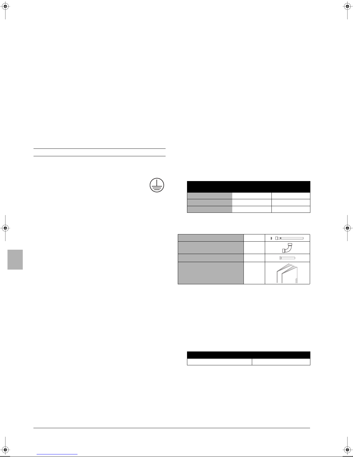
2.2. Standard supplied accessories
(*)
Gas line piping (1)
Gas line piping (2)(*)
Gas line piping (3)(*)
Installation manual
Operation manual
(*) Only for U-6ML5.
+ copper gasket
Location of accessories: refer to figure 1.
1
Accessories
1
1
1
1
1
+
2.3. Optional accessories
To install the above outdoor units, the following optional parts are
also required.
■
Refrigerant branching kit (for R410A only: Always use an
appropriate kit dedicated for your system.)
Refnet header
CZ-P29HK12Q CZ-P20BK12Q
Refnet joint
To select an optimum refrigerant branching kit, refer to "Refrigerant
branch kit selection" on page 9.
2.4. Technical and electrical specifications
Refer to the Engineering Data Book for the complete list of
specifications.
Installation manual
2
U-4~6ML5DPQ + U-4~6ML5XPQ
Urban Multi air conditioner
4PW40731-1

3. B
EFORE INSTALLATION
Since design pressure is 4.0 MPa or 40 bar, pipes of larger
wall thickness may be required. Refer to paragraph
"7.1. Selection of piping material" on page 6.
3.1. Precautions for R410A
■
The refrigerant requires strict cautions for keeping the system
clean, dry and tight.
- Clean and dry
Foreign materials (including mineral oils or moisture) should be
prevented from getting mixed into the system.
- Tight
Read "8. Precautions on refrigerant piping" on page 6 carefully
and follow these procedures correctly.
■
Since R410A is a mixed refrigerant, the required additional
refrigerant must be charged in its liquid state. (If the refrigerant
is in state of gas, its composition changes and the system will
not work properly).
■
The connected indoor units must be indoor units designed
exclusively for R410A.
3.2. Installation
■
For installation of the indoor unit(s), refer to the indoor unit
installation manual.
■
Never operate the air conditioner with the discharge pipe
thermistor (R2T), suction pipe thermistor (R3T) and pressure
sensors (S1NPH, S1NPL) removed. Such operation may burn
out the compressor.
■
Be sure to confirm the model name and the serial no. of the
outer (front) plates when attaching/detaching the plates to avoid
mistakes.
■
When closing the service panels, take care that the tightening
torque does not exceed 4.1 N•m.
1
Select an installation site where the following conditions are
satisfied and that meets with your customer's approval.
- Places which are well-ventilated.
- Places where the unit does not bother next-door neighbours.
- Safe places which can withstand the unit's weight and
vibration and where the unit can be installed level.
- Places where there is no possibility of flammable gas or
product leak.
- Places where servicing space can be well ensured.
- Places where the indoor and outdoor units' piping and wiring
lengths come within the allowable ranges.
- Places where water leaking from the unit cannot cause
damage to the location (e.g. in case of a blocked drain pipe).
- Places where the rain can be avoided as much as possible.
2
When installing the unit in a place exposed to strong wind, pay
special attention to the following.
Strong winds of 5 m/sec or more blowing against the outdoor
unit's air outlet causes short circuit (suction of discharge air),
and this may have the following consequences:
- Deterioration of the operational capacity.
-Frequent frost acceleration in heating operation.
- Disruption of operation due to rise of high pressure.
- When a strong wind blows continuously on the face of the
unit, the fan can start rotating very fast until it breaks.
Refer to the figures for installation of this unit in a place where
the wind direction can be foreseen.
■
Tu rn the air outlet side toward the building's wall, fence or
screen.
3.3. Handling
As shown in the figure, bring the unit slowly by grabbing the left and
right grips.
Place your hands on the corner instead of holding the suction inlet in
the side of the casing, otherwise the casing could be deformed.
Ta ke care not to let hands or objects come in contact with
rear fins.
4. S
This is a class A product. In a domestic environment this product may
cause radio interference in which case the user may be required to
take adequate measures.
ELECTING INSTALLATION SITE
■
Make sure to provide for adequate measures in order
to prevent that the outdoor unit be used as a shelter
by small animals.
■
Small animals making contact with electrical parts can
cause malfunctions, smoke or fire. Please instruct the
customer to keep the area around the unit clean.
Make sure there is enough room to do the installation
■
Set the outlet side at a right angle to the direction of the wind.
Strong wind
Blown air Strong wind
3
Prepare a water drainage channel around the foundation, to
drain waste water from around the unit.
4
If the water drainage of the unit is not easy, please build up the
unit on a foundation of concrete blocks, etc. (the height of the
foundation should be maximum 150 mm).
5
If you install the unit on a frame, please install a waterproof plate
within 150 mm of the underside of the unit in order to prevent the
invasion of water from the lower direction.
6
When installing the unit in a place frequently exposed to snow,
pay special attention to the following:
- Elevate the foundation as high as possible.
- Construct a large canopy (field supply).
- Remove the rear suction grille to prevent snow from
accumulating on the rear fins.
U-4~6ML5DPQ + U-4~6ML5XPQ
Urban Multi air conditioner
4PW40731-1
Installation manual
3

7
The outdoor unit may short circuit depending on its environment,
so use the louvers (field supply).
8
If you install the unit on a building frame,
please install a waterproof plate (within
150 mm of the underside of the unit) or
use a drain plug kit (option) in order to
avoid the drain water dripping.
5.1. Installation method for prevention of falling over
If it is necessary to prevent the unit from falling over, install as shown
in the figure.
■
prepare all 4 wires as indicated in the drawing
■
unscrew the top plate at the 4 locations indicated A and B
■
put the screws through the nooses and screw them back tight
The equipment described in this manual may cause
electronic noise generated from radio-frequency energy.
The equipment complies to specifications that are
designed to provide reasonable protection against such
interference. However, there is no guarantee that
interference will not occur in a particular installation.
It is therefore recommended to install the equipment and
electric wires keeping proper distances away from stereo
equipment, personal computers, etc... (See figure 2)
1 Personal computer or radio
2 Fuse
3 Earth leakage breaker
4 Remote controller
5 Cool/heat selector
6 Indoor unit
In extreme circumstances you should keep distances of
3 m or more and use conduit tubes for power and
transmission lines.
5. P
■
RECAUTIONS ON INSTALLATION
Check the strength and level of the installation ground so that
the unit will not cause any operating vibration or noise after
installation.
■
In accordance with the foundation drawing in the figure, fix the
unit securely by means of the foundation bolts. (Prepare four
sets of M12 foundation bolts, nuts and washers each which are
available on the market.)
■
It is best to screw in the foundation bolts until their length are
20 mm from the foundation surface.
A
140620
350
(345-355)
C
289
219
45
A
B
C
140
117
421
612
Discharge side
Bottom view (mm)
Drain hole
B
AA
B
C
A
location of the 2 fixation holes on the front side of the unit
B
location of the 2 fixation holes on the rear side of the unit
C
wires: field supply
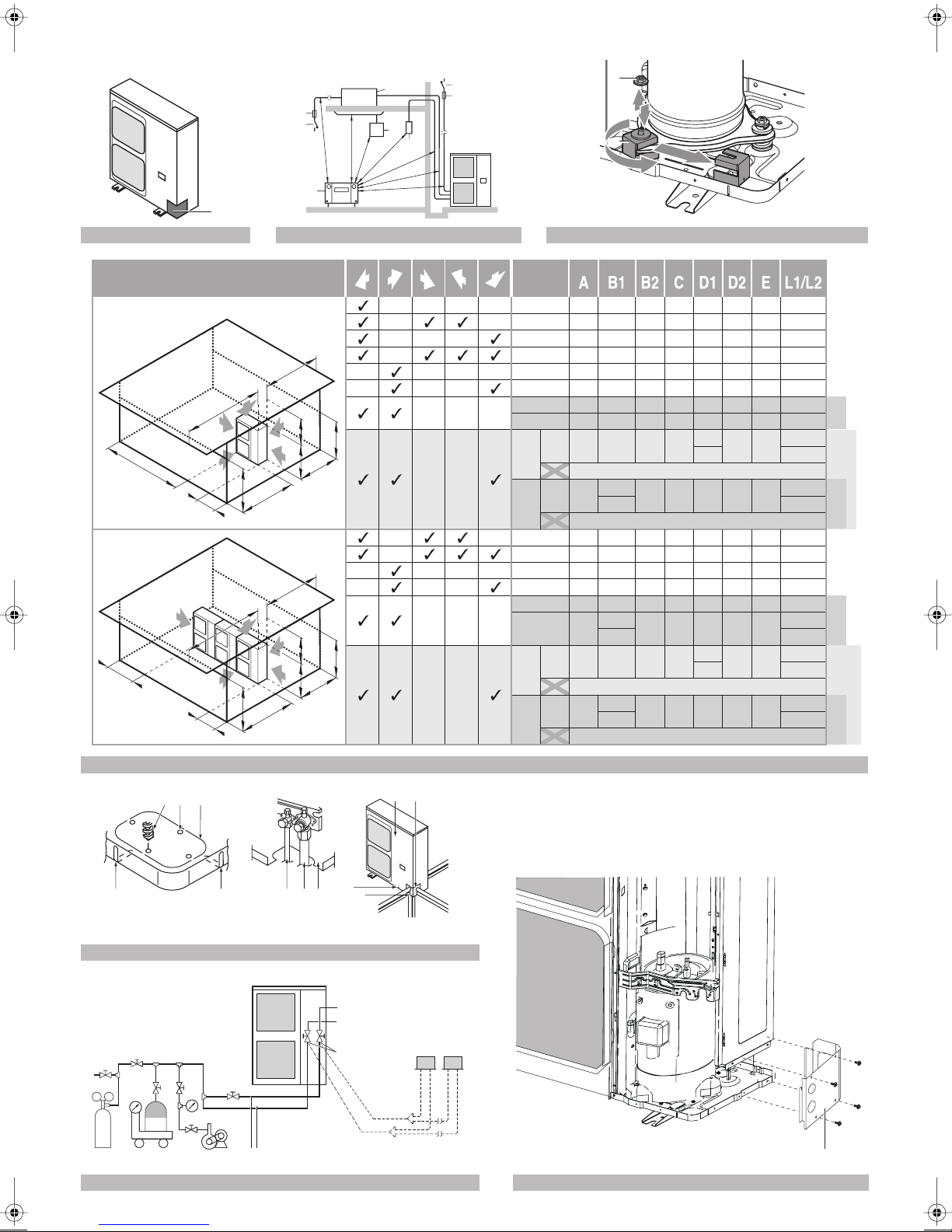
5.2. Method for removing transportation stay
The yellow transportation stay installed over the compressor leg for
protecting the unit during transport must be removed. Proceed as
shown in figure 3 and described below.
A
Compressor
B
Fixing nut
C
Tr ansportation stay
1
Slightly loosen the fixing nut (B).
2
Remove the transportation stay (C) as shown in figure 3.
3
Tighten the fixing nut (B) again.
CAUTION
If the unit is operated with the transportation stay attached,
abnormal vibration or noise may be generated.
5.3. Method for installing drain piping
Depending on installation site, it may be required to install drain plug
for drainage (option kit).
In cold areas, do not use a drain hose with the outdoor unit.
Otherwise, drain water may freeze, impairing the heating
20
performance.
1
See figure below for installation of the drain plug.
Installation manual
4
A
Drain socket
B
Drain cap
C
Drain receiver
D
Insulation tape
2
Connect a field supplied vinyl hose (internal diameter of 25 mm)
to the drain socket (A).
If the hose is too long and hangs down, fix it carefully to prevent
kinks.
U-4~6ML5DPQ + U-4~6ML5XPQ
Urban Multi air conditioner
4PW40731-1
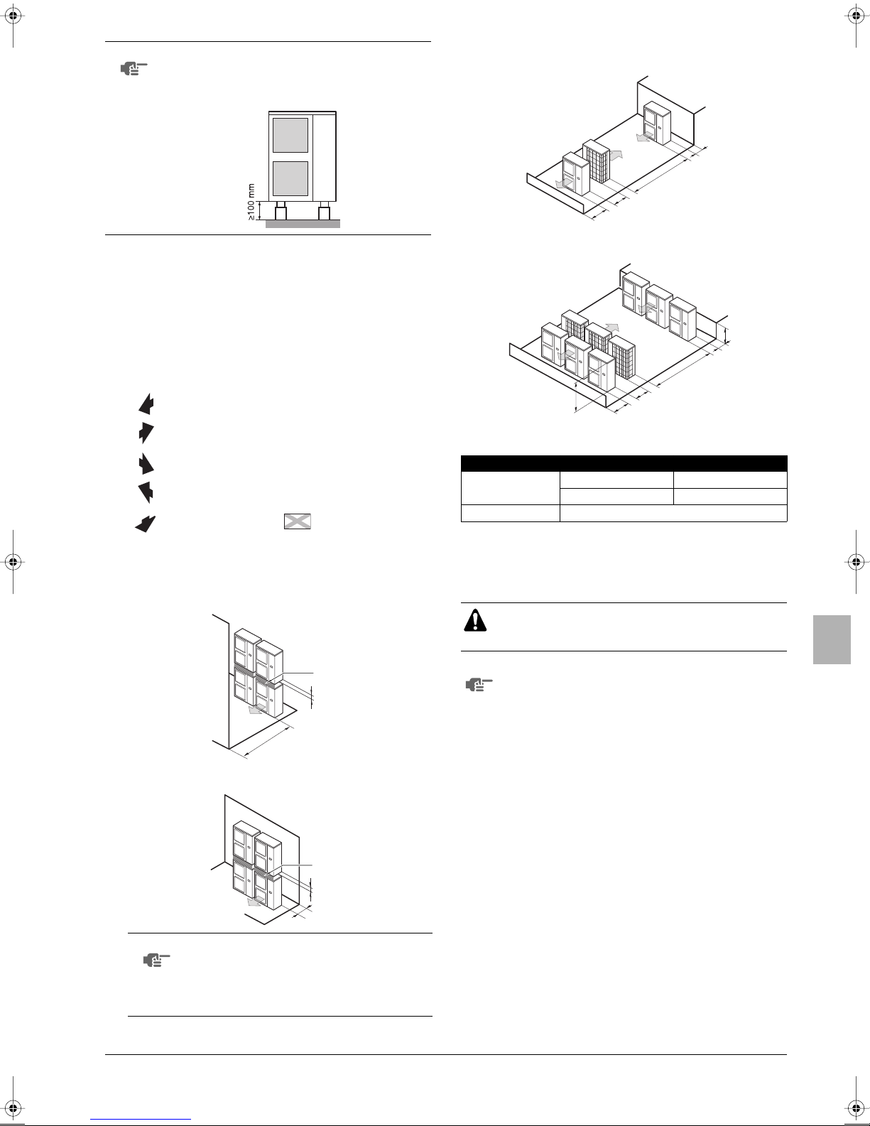
NOTE
000
000
00
000
If drain holes of the outdoor unit are covered by a
mounting base or by floor surface, raise the unit in
order to provide a free space of more than 100 mm
under the outdoor unit.
NSTALLATION SERVICING SPACE
6. I
■
The connection piping outlet direction in the installation shown in
figure 4 is frontward or downward. The unit of numeric values is
mm.
■
When routing the piping backward, secure space of ≥250 mm on
the right side of the unit.
(A) In case of non-stacked installation (See figure 4)
Suction side obstacle
Discharge side obstacle
Left side obstacle
Right side obstacle
Top side obstacle
1 In these cases, close the
bottom of the installation
frame to prevent the
discharged air from
being bypassed
2 In these cases, only 2
units can be installed.
3 In these cases, no
restriction of height L1.
This situation is not
allowed
(C) In case of multiple-row installation (for roof top use, etc.)
1.
In case of installing one unit per row.
≥100
≥2
≥2
≥1
2.
In case of installing multiple units (2 units or more) in lateral
connection per row.
L
A
≥3000
H
≥600
≥1500
Relation of dimensions between H, A and L is shown in the table
below.
L A
L≤H
H<L Installation impossible
0<L≤1/2H 250
1/2H<L≤H 300
Obstacle is present
✓
(B) In case of stacked installation
1.
In case obstacles exist in front of the outlet side.
2.
In case obstacles exist in front of the air inlet.
NOTE
■ Do not stack more than one unit.
■ About 100 mm is required as the dimension
for laying the upper outdoor unit's drain pipe.
■ Get the portion A sealed so that air from the
outlet does not bypass.
7. R
EFRIGERANT PIPE SIZE AND ALLOWABLE
PIPE LENGTH
All field piping must be installed by a licensed refrigeration
technician and must comply with relevant local and
national regulations.
A
100
≥1
A
100
≥300
To persons in charge of piping work:
■ Be sure to open the stop valve after piping installing
and vacuuming is complete. (Running the system with
the valve closed may break the compressor.)
■ It is forbidden to discharge refrigerant into the
atmosphere. Collect the refrigerant in accordance
with the freon collection and destruction law.
■ Do not use flux when brazing the refrigerant piping.
For brazing, use phosphor copper brazing filler metal
(BCuP) which does not require a flux.
(If a chlorine flux is used, the piping will corrode, and if
the flux contains fluoride, it will cause the coolant oil to
deteriorate, adversely affecting the coolant piping
system.
U-4~6ML5DPQ + U-4~6ML5XPQ
Urban Multi air conditioner
4PW40731-1
Installation manual
5
7.1. Selection of piping material
■ Foreign materials inside pipes (including oils for fabrication)
must be ≤30 mg/10 m.
■ Construction material: phosphoric acid deoxidized seamless
copper for refrigerant.
■ Temper grade: use piping with temper grade in function of the
pipe diameter as listed in table below.
■ The pipe thickness of the refrigerant piping should comply with
relevant local and national regulations. The minimal pipe
thickness for R410A piping must be in accordance with the table
below.
Temper grade of piping
Pipe Ø
6.4 / 9.5 / 12.7 O 0.80
15.9 O 1
19.1 1/2H 1
O = Annealed
1/2H = Half hard
material
■ Make sure to use the particular branches of piping that have
been selected.
■ In case the required pipe sizes (inch sizes) are not available, it is
also allowed to use other diameters (mm sizes), taken the
following into account:
■ select the pipe size nearest to the required size.
■ use the suitable adapters for the change-over from inch to
mm pipes (field supply).
Minimal thickness t
(mm)
■ Always use the supplied copper gasket when connecting the
gas pipe supplied with the unit. See "9. Refrigerant piping" on
page 7.
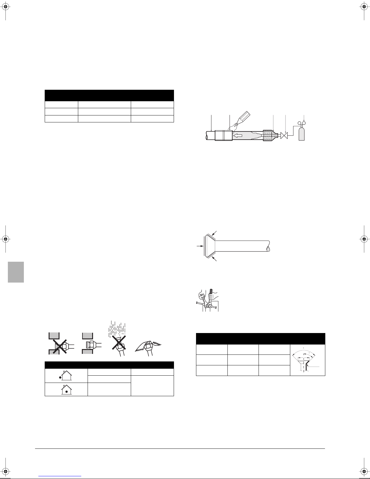
8.1. Cautions for brazing
■ Be sure to carry out a nitrogen blow when brazing.
Brazing without carrying out nitrogen replacement or releasing
nitrogen into the piping will create large quantities of oxidized
film on the inside of the pipes, adversely affecting valves and
compressors in the refrigerating system and preventing normal
operation.
■ When brazing while inserting nitrogen into the piping, nitrogen
must be set to 0.02 MPa with a pressure-reducing valve (=just
enough so that it can be felt on the skin).
12 345
6
1 Refrigerant piping
2 Part to be brazed
3 Taping
4 Hands valve
5 Pressure-reducing valve
6 Nitrogen
6
8. PRECAUTIONS ON REFRIGERANT PIPING
■ Do not allow anything other than the designated refrigerant to
get mixed into the freezing cycle, such as air, etc. If any
refrigerant gas leaks while working on the unit, ventilate the
room thoroughly right away.
■ Use R410A only when adding refrigerant
Installation tools:
Make sure to use installation tools (gauge manifold charge hose,
etc.) that are exclusively used for R410A installations to withstand
the pressure and to prevent foreign materials (e.g. mineral oils
and moisture) from mixing into the system.
Vacuum pump:
Use a 2-stage vacuum pump with a non-return valve
Make sure the pump oil does not flow oppositely into the system
while the pump is not working.
Use a vacuum pump which can evacuate to –100.7 kPa (5 Torr,
–755 mm Hg).
■ In order to prevent dirt, liquid or dust from entering the piping,
cure the piping with a pinch or taping.
Installation period Protection method
More than a month Pinch the pipe
Less than a month
Regardless of the
period
Pinch or tape the
pipe
8.2. Cautions for flare connection
■ See the following table for flare part machining dimensions.
■ When connecting the flare nuts, apply refrigerant ether or ester
oil to the inside and outside of the flares and turn them three or
four times at first.
■ When loosening a flare nut, always use two wrenches in
combination. When connecting the piping, always use a spanner
and torque wrench in combination to tighten the flare nut.
1 Piping union
2 Spanner
3 Flare nut
12 3 4
■ See the following table for tightening torque.
(Applying too much torque may cause the flares to crack.)
Pipe size
Ø9.5 32.7~39.9 12.8~13.2
Ø15.9 61.8~75.4 19.3~19.7
Ø19.1 97.2~118.6 12.3~23.7
■ After all the piping has been connected, use nitrogen to perform
a gas leak check.
4 Torque wrench
Tightening
torque (N•m)
A (mm) Flare shape
±2
90
45
±2
A
R=0.4~0.8
Great caution is needed when passing copper tubes through
walls.
■ For handling of stop valves, refer to "9.3. How to use the stop
valve" on page 8.
■ Only use the flare nuts included with the unit. Using different
flare nuts may cause the refrigerant to leak.
Installation manual
6
U-4~6ML5DPQ + U-4~6ML5XPQ
Urban Multi air conditioner
4PW40731-1
NOTE
You must use a torque wrench but if you are obliged to
install the unit without a torque wrench, you may follow
the installation method mentioned below.
After the work is finished, make sure to check that
there is no gas leak.
When you keep on tightening the flare nut with a
spanner, there is a point where the tightening torque
suddenly increases. From that position, further tighten
the flare nut within the angle shown below:
Further tightening
Pipe size
Ø9.5 (3/8") 60~90° ±200 mm
Ø15.9 (5/8") 30~60° ±300 mm
Ø19.1 (5/8") 20~35° ±450 mm
angle
Recommended
arm length of tool
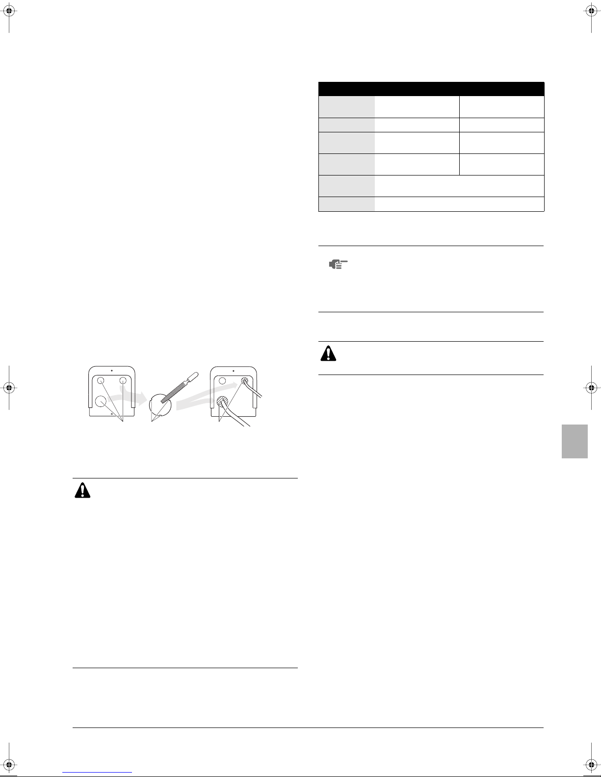
9. REFRIGERANT PIPING
■ Field pipes can be installed in four directions.
Figure - Field pipes in four directions (See figure 5)
1 Drill
2 Center area around knockout hole
3 Knockout hole
4 Slit
5 Connecting pipe liquid (field supply)
6 Bottom frame
7 Front plate
8 Pipe outlet plate
9 Screw front plate
10 Pipe outlet plate screw
11 Connecting pipe gas (field supply, except U-6ML5)
A Forward
B Backward
C Sideways
D Downward
When connecting the piping in the lateral direction (on the rear),
remove the piping cover (rear) in reference to figure 7.
1 Piping cover (rear)
■ To install the connecting pipe to the unit in a downward direction,
make a knockout hole by penetrating the center area around the
knockout hole using a Ø6 mm drill. (See figure 5).
■ Cutting out the two slits makes it possible to install as shown in
figure 5.
(Use a metal saw to cut out the slits.)
■ After knocking out the knock-out, it is recommended to apply
repair paint to the edge and the surrounding end surfaces to
prevent rusting.
For U-6ML5 only
The size of the gas side stop valve is Ø15.9 while the inter-unit piping
is Ø19.1. Use the standard supplied accessory piping to make the
connection. See figure 15.
A Front connection
B Rear connection
C Side connection
D Bottom connection
1 Gas line piping + copper gasket supplied with the unit (make sure
to always use the copper gasket).
2 Gas line piping supplied with the unit
3 Gas piping (field supply)
4 Cut to the appropriate length.
5 Gas line piping supplied with the unit
9.1. Preventing foreign objects from entering
Plug the pipe through-holes with putty or insulating material (field
supply) to stop up all gaps, as shown in the figure.
1
1 Putty or insulating material (field
supply)
Insects or small animals entering the outdoor unit may cause a short
circuit in the electrical box.
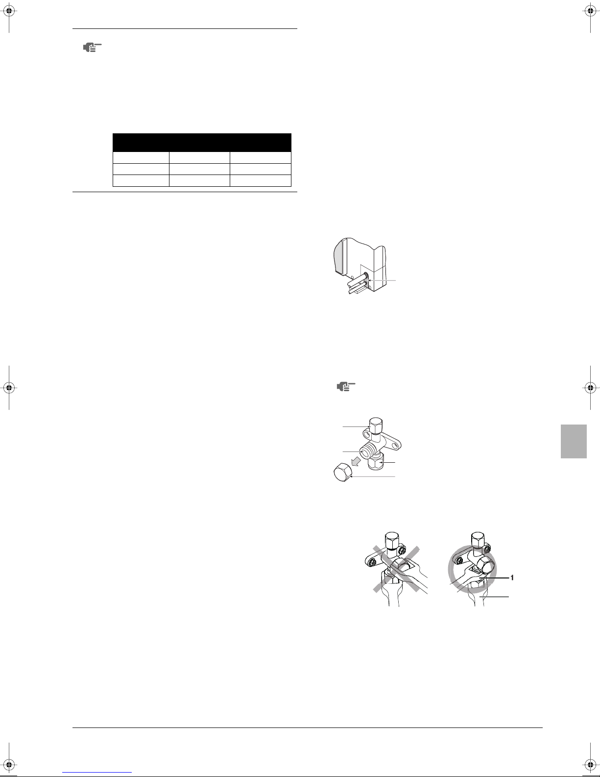
9.2. Cautions for handling stop valve
■ The stop valves for indoor-outdoor connecting piping are closed
at shipment from the factory.
Make sure to keep the valve open during operation.
The names of parts of the stop valve are shown in the figure.
1
2
3
4
■ Since the side boards may be deformed if only a torque wrench
is used when loosening or tightening flare nuts, always lock the
stop valve with a wrench and then use a torque wrench.
Do not place wrenches on the valve cover.
1 Service port
2 Stop valve
3 Field piping connection
4 Valve cover
U-4~6ML5DPQ + U-4~6ML5XPQ
Urban Multi air conditioner
4PW40731-1
1 Spanner
2 Torque wrench
Do not apply force on the valve cover, this may result in a
refrigerant leak.
Installation manual
7
■ For cooling operation under low ambient temperature or any
other operation under low pressure, apply silicon pad or similar
to prevent freezing of the gas stop valve flare nut (see figure).
Freezing of the flare nut may cause refrigerant leak.
Silicon sealing pad
(Make sure there is no gap)
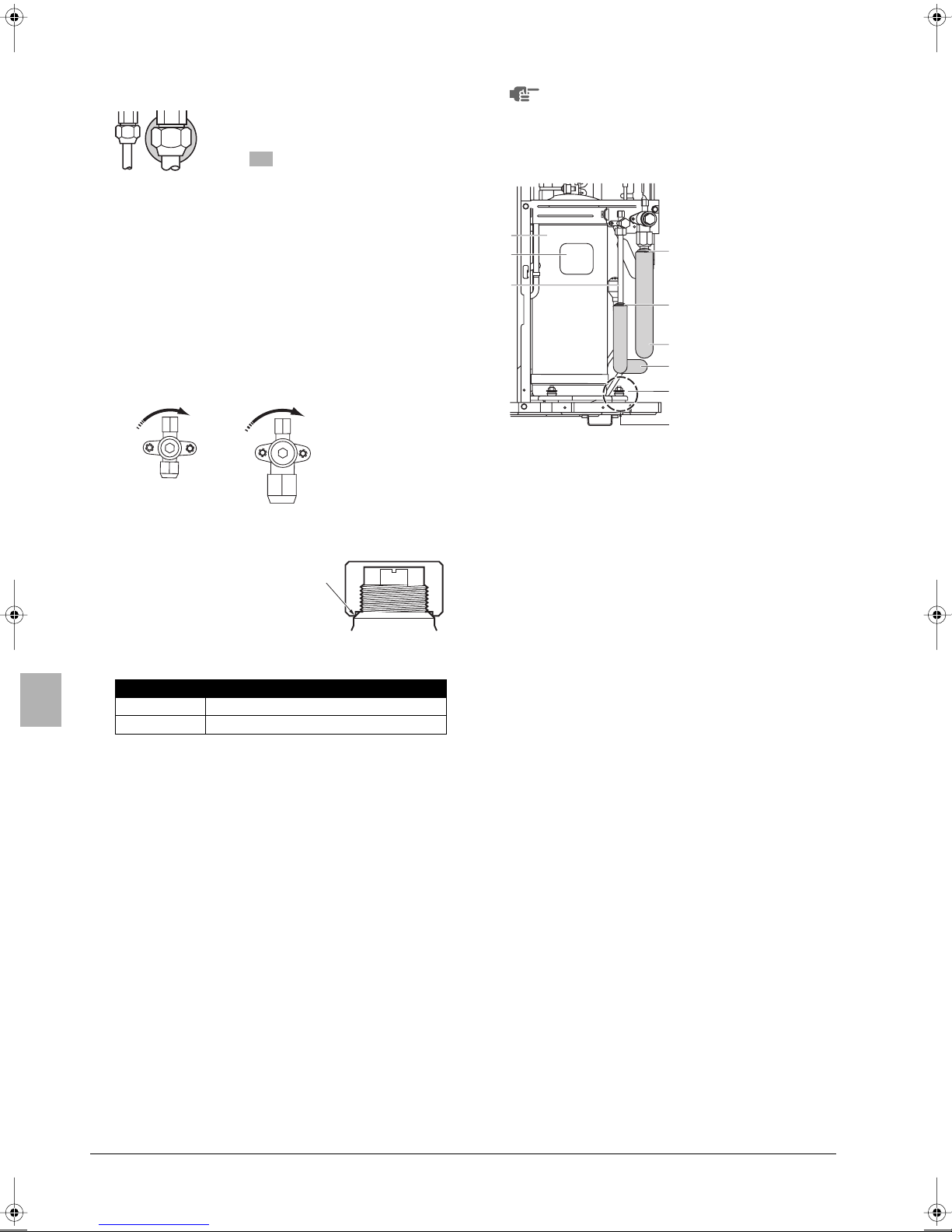
9.3. How to use the stop valve
Use hexagonal wrenches 4 mm and 6 mm.
■ Opening the valve
1. Place the hex wrench on the valve bar and turn counter-
clockwise.
2. Stop when the valve bar no longer turns. It is now open.
■ Closing the valve
1. Place the hex wrench on the valve bar and turn clockwise.
2. Stop when the valve bar no longer turns. It is now closed.
Closing direction
Liquid side Gas side
■ Be sure to insulate the liquid and gas-side field piping and the
refrigerant branch kit.
Any exposed piping may cause condensation or burns
if touched.
(The highest temperature that the gas-side piping can reach is
around 120°C, so be sure to use insulating material which is
very resistant.)
1
2
3
4
1 Compressor
2 Te r minal cover
3 Indoor and outdoor
4
4 Corking, etc.
5
5 Insulation material
5
6 Bolts
6
A Be careful with pipe,
A
field piping
(field supply)
bolt and outer panel
connections
9.4. Cautions for handling the valve cover
■ The valve cover is sealed where
indicated by the arrow.
Ta ke care not to damage it.
■ After operating the valve, be sure to tighten the valve cover
properly.
Tightening torque
Liquid pipe 13.5~16.5 N•m
Gas pipe 22.5~27.5 N•m
■ Check for refrigerant leakage after tightening the cap.
9.5. Cautions for handling service port
After the work, tighten the valve cover in place.
Tightening torque: 11.5~13.9 N•m
9.6. Precautions when connecting field piping and
regarding insulation
■ Be careful not to let the indoor and outdoor branch piping come
into contact with the compressor terminal cover.
If the liquid-side piping insulation might come into contact with it,
adjust the height as shown in the figure below. Also, make sure
the field piping does not touch the bolts or outer panels of the
compressor.
■ When the outdoor unit is installed above the indoor unit the
following can occur:
The condensated water on the stop valve can move to the
indoor unit. To avoid this, please cover the stop valve with
sealing material.
■ If the temperature is higher than 30°C and the humidity is higher
than RH 80%, then the thickness of the sealing materials should
be at least 20 mm in order to avoid condensation on the surface
of the sealing.
Installation manual
8
U-4~6ML5DPQ + U-4~6ML5XPQ
Urban Multi air conditioner
4PW40731-1
H1
Outdoor unit
capacity type
Piping size (outer diameter x minimum
thickness)
Gas pipe Liquid pipe
U-4+5ML5 Ø15.9x1.0
(Ø19.1x1.0)
Ø9.5x0.8
U-6ML5 Ø19.1x1.0
(Ø22.2x1.0)
8
H2
hi
g
f
cde
a
1234567
b
H2
k
78
j
B
h
i
g
A
b
123456
cde f
a
H1
Piping size
Gas pipe Liquid pipe
(outer diameter x minimum thickness)
Indoor capacity
index
20+25+32+40+50 Ø12.7x0.8 Ø6.4x0.8
Gas pipe Liquid pipe
Ø15.9x1.0 Ø9.5x0.8
63+80+100+125 Ø15.9x1.0 Ø9.5x0.8
connection size of indoor unit.
• Pipe size for direct connection to indoor unit must be the same as the
C. Piping between refrigerant branch kit and indoor unit
Outdoor unit capacity type Refrigerant branch kit name
U-4~6ML5 CZ-P29HK12Q
Piping size (outer diameter x minimum thickness)
• Use the pipe size from the following table.
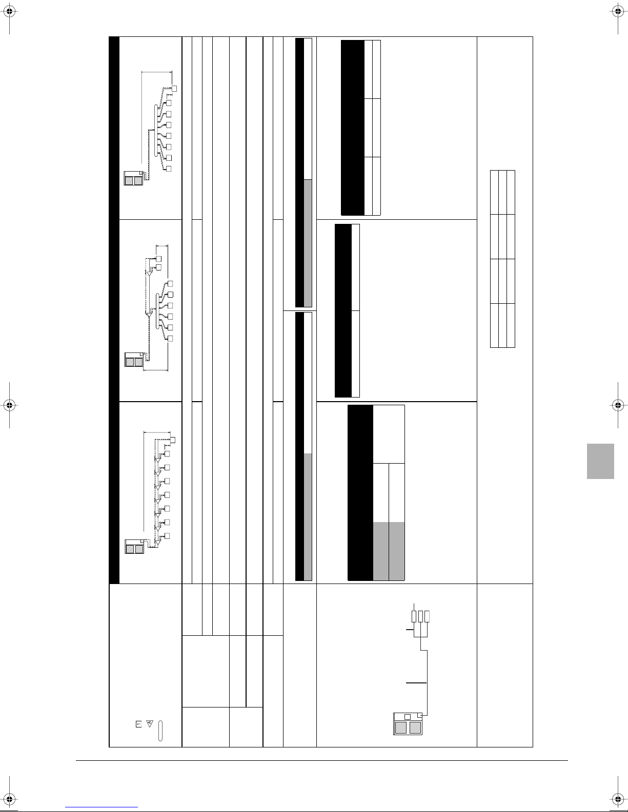
B. Piping between refrigerant branch kits
a: Ø9.5x30 m d: Ø9.5x13 m g: Ø6.4x10 m j: Ø6.4x10 m
Example for refrigerant branch using line branch pipe and header branch pipe
x0.022
b: Ø9.5x10 m e: Ø6.4x10 m h: Ø6.4x20 m k: Ø6.4x9 m
c: Ø9.5x10 m f: Ø6.4x10 m i: Ø9.5x10 m
)
R=[73 x 0.054] + [69 x 0.022] = 5.46 ⇒ 5.5 kg
p
H1
8
H2
g
Branch with line branch pipe Branch with line branch pipe and header branch pipe Branch with header branch pipe
Example of connection
(Connection of 8 indoor units Heat pump system)
ABCDEFG
ab c d e f
indoor unit
line branch pipe
1234567
hi j k l mn
header branch pipe
Pipe length between outdoor and indoor units ≤150 m
[Example] unit 8: a+b+c+d+e+f+g+p≤150 m [Example] unit 6: a+b+h≤150 m, unit 8: a+i+k≤150 m [Example] unit 8: a+i≤150 m
Actual pipe length
Equivalent length Equivalent pipe length between outdoor and indoor units ≤175 m (Assume equivalent pipe length of line branch pipe to be 0.5 m and of the header branch pipe to be 1.0 m. (for calculation purposes))
Total extension
Between outdoor and
indoor units
Maximum
allowable
length
Total piping length from outdoor unit to all indoor units between 10 m and 300 m
length
Difference in height between outdoor and indoor units (H1)≤50 m (≤40 m if outdoor unit is located in a lower position).
Difference in height between adjacent indoor units (H2)≤15 m
Pipe length from first refrigerant branch kit (either line branch pipe or header branch pipe) to indoor unit ≤40 m
Difference in
height
Difference in
height
Between outdoor and
indoor units
Between indoor and indoor
units
Allowable
height
Outdoor unit capacity type Refrigerant branch kit name
U-4~6ML5 CZ-P20BK12Q
[Example] unit 8: b+c+d+e+f+g+p≤40 m [Example] unit 6: b+h≤40 m, unit 8: i+k≤40 m [Example] unit 8: i≤40 m
Use the following line branch pipe Use the following header branch pipe
Allowable length after the branch Actual pipe length
Refrigerant branch kit selection
• Match to the size of the connection piping on the outdoor unit.
A. Piping between outdoor unit and refrigerant branch kit
Refrigerant branch kits can only be used with R410A.
Pipe size selection
Caution on selecting connection pipes
If the overall equivalent piping length is ≥90 m, be sure to
Outdoor unit connection piping size
1 2
enlarge the pipe diameter of the gas-side main piping. If the
recommended pipe size is not available, stick to the original
pipe diameter (which may result in a small capacity decrease).
[Gas side]
U-4+5ML5: Ø15.9➝Ø19.1
U-6ML5: Ø19.1➝Ø22.2
3
Total length (m) of liquid
Total length (m) of liquid
1 Main pipe (enlarge)
2 First refrigerant branch kit
3 Indoor unit
How to calculate the additional refrigerant to be charged
Additional refrigerant to be charged R (kg)
piping size at Ø6.4
(
x0.054+
)
piping size at Ø9.5
(
R=
R should be rounded off in units of 0.1 kg
U-4~6ML5DPQ + U-4~6ML5XPQ
Urban Multi air conditioner
4PW40731-1
Installation manual
9
9.7. Leak test and vacuum drying
The units were checked for leaks by the manufacturer.
See figure 6 and refer to "Additional refrigerant charge" on page 10
for nomenclature of the parts in figure 6.
• Confirm that the gas and liquid line stop valves are firmly closed
before pressure test or vacuuming.
• Make sure that valve A is completely open.
Air tight test and vacuum drying
■ Air tight test: Make sure to use nitrogen gas. (For the service
port position, refer to "9.2. Cautions for handling stop valve" on
page 7.
■ Pressurize the liquid and gas pipes to 4.0 MPa (40 bar) (do not
pressurize more than 4.0 MPa (40 bar)). If the pressure does not
drop within 24 hours, the system passes the test. If the pressure
drops, check where the nitrogen leaks from.
■ Vacuum drying: Use a vacuum pump which can evacuate to
–100.7 kPa (5 Torr, –755 mm Hg)
1. Evacuate the system from the liquid and gas pipes by using a
vacuum pump for more than 2 hours and bring the system to
–100.7 kPa. After keeping the system under that condition for
more than 1 hour, check if the vacuum gauge rises or not. If it
rises, the system may either contain moisture inside or have
leaks.
2. Following should be executed if there is a possibility of moisture
remaining inside the pipe (if piping work is carried out during the
raining season or over a long period of time, rainwater may enter
the pipe during work).
After evacuating the system for 2 hours, pressurize the system to
0.05 MPa (vacuum break) with nitrogen gas and evacuate the
system again using the vacuum pump for 1 hour to –100.7 kPa
(vacuum drying). If the system cannot be evacuated to –100.7 kPa
within 2 hours, repeat the operation of vacuum break and vacuum
drying.
Then, after leaving the system in vacuum for 1 hour, confirm that
the vacuum gauge does not rise.
4 Siphon system
5 Measuring instrument
6 Vacuum pomp
7 Valve A
8 Gas line stop valve
9 Outdoor unit
10 Liquid line stop valve
11 Indoor unit
12 Stop valve service port
13 Charge hose
To avoid compressor breakdown. Do not charge the refrigerant
more than the specified amount.
■ This outdoor unit is factory charged with refrigerant and
depending on pipe sizes and pipe lengths some systems require
additional charging of refrigerant. See "How to calculate the
additional refrigerant to be charged" on page 9.
■ In case re-charge is required, refer to the nameplate of the unit.
The nameplate states the type of refrigerant and necessary
amount.
Precautions when adding R410A
Be sure to charge the specified amount of refrigerant in liquid state to
the liquid pipe.
Since this refrigerant is a mixed refrigerant, adding it in gas form may
cause the refrigerant composition to change, preventing normal
operation.
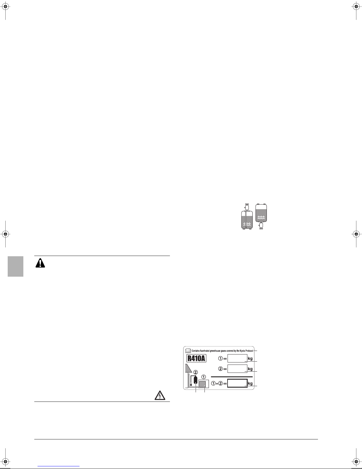
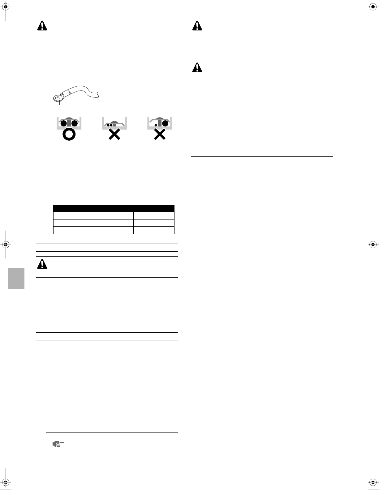
■ Before charging, check whether the refrigerant cylinder is
equipped with a siphon tube or not.
Charge the liquid
refrigerant with the cylinder
in upright position.
Charge the liquid
refrigerant with the cylinder
in up-side-down position.
10. ADDITIONAL REFRIGERANT CHARGE
■ Refrigerant cannot be charged until field wiring has
been completed.
■ Refrigerant may only be charged after performing the
leak test and the vacuum drying (see above).
■ When charging a system, care shall be taken that its
maximum permissible charge is never exceeded, in
view of the danger of liquid hammer.
■ Charging with an unsuitable substance may cause
explosions and accidents, so always ensure that the
appropriate refrigerant (R410A) is charged.
■ Refrigerant containers shall be opened slowly.
■ Always use protective gloves and protect your eyes
when charging refrigerant.
■ When performing service on the unit requiring the
refrigerant system to be opened, refrigerant must be
evacuated according to local regulations.
■ Do not use the automatic refrigerant charging function
while working on the indoor units.
When using the automatic refrigerant charging
function, the indoor units operate automatically as
well as the outdoor unit.
■ When the power is on, please close the front
panel when leaving the unit.
See figure 6.
1 Pressure reducing valve
2 Nitrogen
3 Tank
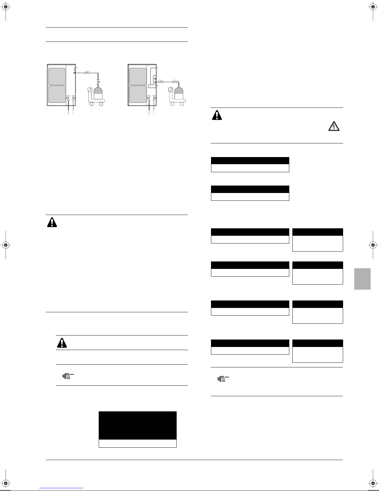
10.1. Important information regarding the refrigerant
used
This product contains fluorinated greenhouse gases covered by the
Kyoto Protocol. Do not vent gases into the atmosphere.
Refrigerant type: R410A
(1)
GWP
value: 1975
(1)
GWP = global warming potential
Please fill in with indelible ink,
■➀ the factory refrigerant charge of the product,
■➁ the additional refrigerant amount charged in the field and
■➀+➁ the total refrigerant charge
on the refrigerant charge label supplied with the product.
The filled out label must be adhered in the proximity of the product
charging port (e.g. onto the inside of the service cover).
1 factory refrigerant charge
4
of the product:
see unit name plate
1
2 additional refrigerant
amount charged in the
2
field
3 total refrigerant charge
3
4 Contains fluorinated
5
6
greenhouse gases
covered by the Kyoto
Protocol
5 outdoor unit
6 refrigerant cylinder and
manifold for charging
Installation manual
10
U-4~6ML5DPQ + U-4~6ML5XPQ
Urban Multi air conditioner
4PW40731-1
10.2. 3 procedures for adding refrigerant
Procedure 1: Adding refrigerant by using the automatic
refrigerant charging function (recommended)
How to connect the tank?
DPQ XPQ
5
4
12
6
7
3
1 Liquid line stop valve
2 Gas line stop valve
3 To indoor unit
4 Service port for adding refrigerant
5 Valve A
6 R410A tank
7 Measuring instrument
8 Pipe fixing plate
When the refrigerant tank is connected and the specified operation is
performed, the appropriate amount of refrigerant will be charged into
the system. After charging, the system will stop automatically. The
refrigerant must be charged according to the procedure described
below.
CAUTION
■ Make sure to turn ON the power 6 hours before
starting the operation. This is necessary to warm the
crankcase by the electric heater.
■ Automatic charging is able to charge 6 kg/hour
refrigerant at an outside temperature of 0°C to 24 kg/
hour refrigerant at an outside temperature of 35°C.
The charging time depends on the amount of charged
refrigerant and on the outside temperature.
■ Automatic refrigerant charging is NOT possible if the
following restrictions are exceeded:
■ Outside temperature: 0°C DB~43°C DB
■ Indoor temperature: 0°C DB~32°C DB
■ Indoor unit connection capacity: 50%~130%
Automatic refrigerant charging procedure
1 Open the liquid and gas side stop valves completely.
Note that valve A must be closed!
2 Turn on the power of the outdoor unit and indoor units.
12
3
8
5
4
6
7
Led state
Throughout the manual the state of the leds is indicated as
follows:
x
OFF
w
ON
c
blinking
❃
ON or OFF
If H2P is lit up, check the type of error based on the error code in
the remote controller and correct the error in accordance with
"12.4. Test operation" on page 19.
4 Automatically charge the refrigerant according to the procedure
described below.
WARNING
Do not touch anything else than the pushbuttons (BS1~5) on the PCB when making
the settings. These settings must be done
with the power on
4.1 Press once.
BS4 TEST
H1P H2P H3P H4P H5P H6P H7P
wwwwwww
4.2 Press for 5 seconds. The unit will start running.
BS4 TEST
H1P H2P H3P H4P H5P H6P H7P
xcxxx
❃❃
If the led display below appears, the automatic refrigerant
charging restriction has been exceeded. Additional refrigerant
must be charged by calculating the additional refrigerant
charging amount.
H1P H2P H3P H4P H5P H6P H7P Description of error
wcccw x x
Inappropriate outdoor
temperature
or
H1P H2P H3P H4P H5P H6P H7P Description of error
wccc x w x
Inappropriate indoor
temperature
If the led display below appears, check the indoor unit
connection capacity.
H1P H2P H3P H4P H5P H6P H7P Description of error
wcccc x w
Inappropriate indoor unit
connection capacity
If the led display below appears, the liquid and gas side stop
valves may be closed.
H1P H2P H3P H4P H5P H6P H7P Description of error
wx
❃❃❃❃❃
Stop valve is closed
NOTE
When an indoor unit is connected to the
refrigerant system and the indoor unit is turned
off, automatic charging will fail.
3 Make sure that the led on the PCB on the outdoor unit are as
shown in the table below. This indicates that the system is
operating normally.
MODE
TEST/HWL
H1P H2P H3P H4P H5P H6P H7P
xxwxxxx
U-4~6ML5DPQ + U-4~6ML5XPQ
Urban Multi air conditioner
4PW40731-1
IND
MASTER
SLAVE
L.N.O.P.
DEMAND
NOTE
If you want to repeat the automatic refrigerant
charging operation from step 4.2, fully open the
liquid and gas side stop valves and press the
BS1 MODE
button once.
4.3 When the led indication becomes as shown in the table below in
about 15 to 30 minutes after start of operation, open valve A at
once to start charging of the refrigerant.
Immediately after starting charging of the refrigerant by opening
valve A, press once. When is not pressed
BS4 TEST BS4 TEST
within 10 minutes after the led indication is shown, charging is
stopped.
Installation manual
11

H1P H2P H3P H4P H5P H6P H7P Code on remote controller
ccc xwxw
PA
4.4 The led indication becomes as shown in the table below during
automatic refrigerant charging.
During automatic refrigerant charging, the remote controller
indicates (test operation) and (external control).
H1P H2P H3P H4P H5P H6P H7P
wc
NOTE
❃❃❃❃❃
If the led display below appears, the refrigerant
tank is empty. Replace the refrigerant tank, open
valve A and re-charge.
H1P H2P H3P H4P H5P H6P H7P Code on remote controller
wcc x xwx
PA
The led indication becomes as shown in the table below when
automatic refrigerant charging is about to end. Prepare to close
the valve on the refrigerant tank.
H1P H2P H3P H4P H5P H6P H7P Code on remote controller
cccwwww
PE
After correcting the problem, press button once and
BS1 MODE
perform automatic refrigerant charging again starting from
step 4.2.
Case 4: Failure
Error code on remote
H1P H2P H3P H4P H5P H6P H7P
xwwxxxx
(*) An error in the system interrupted the operation of the unit. Check the
error by using the error code displayed on the remote controller. For an
explanation of the error codes, see "Error codes on the remote controller"
on page 20 and solve the problem.
After correcting the problem, press button once and
BS1 MODE
controller
See footnote
(*)
perform automatic refrigerant charging again starting from
step 4.2.
5 When charging is complete, determine the weight of refrigerant
that was added and fill in the amount in the "Additional
refrigerant charge label" attached to service precautions plate
on the unit.
6 After adding the refrigerant, do not forget to close the lid of the
service port. The tightening torque for the lid is 11.5~13.9 N•m.
NOTE
It is possible that the code PE is not shown on the
remote controller but this does not indicate a
malfunction. The led indication can immediately
shift to the situation as shown in "Case 1:
Charging complete" on page 12.
4.5 When the led indication becomes as shown in the table below,
quickly close valve A and follow instructions as described below.
CAUTION
■ When adding refrigerant is done or when
pausing, close the valve on the refrigerant tank
immediately.
More refrigerant might be charged by any
remaining pressure after the machine is stopped.
■ The outdoor fan may keep rotating a little bit
more, but this does not indicate a malfunction.
Case 1: Charging complete
H1P H2P H3P H4P H5P H6P H7P Code on remote controller
wccwwww
Charging of the refrigerant is complete. Press
P9
BS1 MODE
button once and go to step 5.
Case 2: Recharging operation
H1P H2P H3P H4P H5P H6P H7P Code on remote controller
wcc x www
Press button once and perform automatic
BS1 MODE
P8
refrigerant charging again starting from Step 4.2.
Case 3: Charging interrupted
H1P H2P H3P H4P H5P H6P H7P Code on remote controller
wcc xxxw
P2
Something is preventing normal operation:
■ Is the gas side stop valve completely open?
■ Are the valve on the refrigerant tank and valve A open?
Check if the button was pressed within 10
BS4 TEST
minutes after the valves were opened.
■ Is the indoor unit air intake vent or outlet vent blocked?
1
DPQ XPQ
2
3
1 Service port for adding refrigerant
2 Liquid line stop valve
3 Gas line stop valve
4 Pipe fixing plate
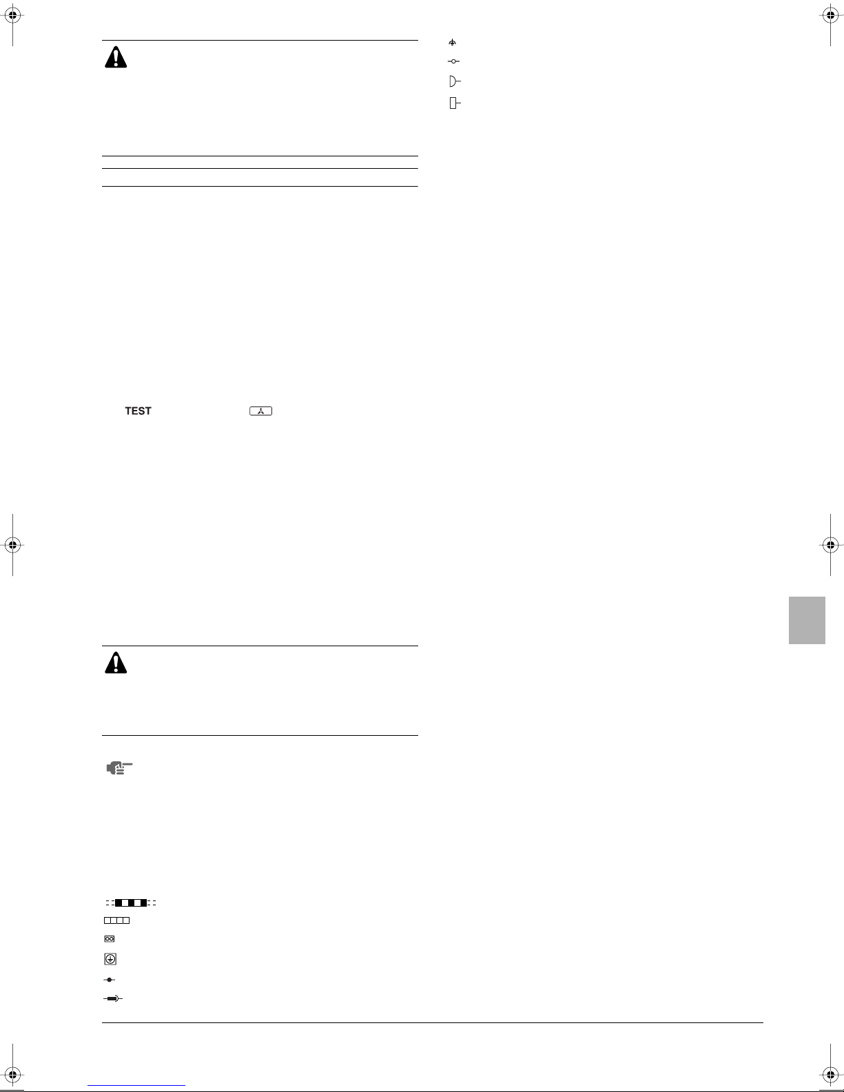
Procedure 2: Charging while the outdoor unit is at a standstill
See figure 6.
1 Determine the weight of refrigerant to be charged additionally
referring to the item "Additional refrigerant charge" in "How to
calculate the additional refrigerant to be charged" on page 9 and
fill in the amount in the "Additional refrigerant charge label"
attached to the unit.
2 After the vacuum drying is finished, open valve A and charge the
additional refrigerant in its liquid state through the service port
on the liquid stop valve taking into account following instructions:
-Turn on the power of the outdoor unit and indoor units.
- Check that gas and liquid stop valves are closed.
- Stop the compressor and charge the specified weight of
refrigerant.
4
2
3
Installation manual
12
U-4~6ML5DPQ + U-4~6ML5XPQ
Urban Multi air conditioner
4PW40731-1
■ To avoid compressor breakdown. Do not charge the
refrigerant more than the specified amount.
■ If the total refrigerant cannot be charged while the
outdoor unit is at a standstill, it is possible to charge
the refrigerant by operating the outdoor unit using the
refrigerant charge function (refer to "Setting mode 2"
on page 18) and follow "Procedure 3: Charging while
the outdoor unit is operating" on page 13.
Procedure 3: Charging while the outdoor unit is operating
See the figure in "How to connect the tank?" on page 11.
1 Completely open the gas side stop valve and liquid side stop
valve. Valve A must be left fully closed.
2 Close the front panel and turn on the power to all indoor units
and the outdoor unit.
3 Open valve A immediately after starting of the compressor.
4 Charge the additional refrigerant in its liquid state through the
service port of the liquid line stop valve.
5 While the unit is at a standstill and under setting mode 2 (refer to
Checks before initial start-up, "Setting the mode" on page 18),
set the required function A (additional refrigerant charging
operation) to (ON). Then operation starts. The blinking H2P
led indicates test operation and the remote controller indicates
6 When the specified amount of refrigerant is charged, push the
BS3 RETURN
■ The operation automatically stops within 30 minutes.
■ If the refrigerant charge cannot be finished within 30 minutes,
repeat step 5.
■ If the operation stops immediately after restart, there is a
possibility that the system is overcharged.
The refrigerant cannot be charged more than this amount.
7 After the refrigerant charge hose is removed, make sure to close
valve A.
ON
(test operation) and (external control).
button. Then operation stops.
11. ELECTRICAL WIRING WORK
■ All wiring must be performed by an authorized
electrician.
■ All field supplied components and all electric
construction should comply with the applicable local
and national codes.
To persons in charge of electrical wiring work:
Do not operate the unit until the refrigerant piping is
complete. (Running it before the piping is ready will break
the compressor.)
11.1. Internal wiring – Parts table
L............................. Live
N............................ Neutral
........... Field wiring
.................... Terminal strip
......................... Connector
......................... Protective earth (screw)
.......................... Connection
....................... Relay connector
...........................Functional earthing
...........................Terminal
..........................Movable connector
..........................Fixed connector
BLU........................Blue
BRN .......................Brown
GRN.......................Green
RED .......................Red
WHT....................... White
YLW ....................... Yellow
ORG....................... Orange
BLK ........................ Black
A1P ........................ Printed circuit board (main)
A2P ........................ Printed circuit board (inverter)
A3P ................ * .....Printed circuit board (noise filter)
A4P ................ * .....Printed circuit board (C/H selector)
BS1~BS5 ............... Push button switch (mode, set, return, test,
reset)
C1~C3....................Capacitor
C4 ..................* .....Capacitor
DS1........................DIP switch
E1HC .....................Crankcase heater
F1U, F4U .......* .....Fuse (T 6.3 A/250 V)
F1U (A1P)......# .....Fuse (T 6.3 A/250 V)
F3U (A1P)......# .....Fuse (T 6.3 A/250 V)
F4U (A1P)......# .....Fuse (T 6.3 A/250 V)
F6U ................ * .....Fuse (T 5.0 A/250 V)
FINTH ............* .....Thermistor (fin)
H1P~H8P...............Light emitting diode (service monitor orange)
Prepare, test: blinking
H2P........................Malfunction detection: light up
HAP................ * ..... Light emitting diode (service monitor green)
HAP (A1P) .....# .....Light emitting diode (service monitor green)
HAP (A2P) .....# .....Light emitting diode (service monitor green)
K1M................ * ..... Magnetic contactor (M1C)
K1M (A1P) .....# .....Magnetic contactor
K1R........................Magnetic relay (Y1S)
K2R........................Magnetic relay (Y2S)
K3R........................Magnetic relay (Y3S)
K4R........................Magnetic relay (E1HC)
K5R........................Magnetic relay
K6R................# .....Magnetic relay
L1R ........................Reactor
M1C .......................Motor (compressor)
M1F........................ Motor (fan) (upper)
M2F........................ Motor (fan) (lower)
PS .......................... Switching power supply
Q1DI.......................Field earth leakage breaker (300 mA)
R1 ..................* .....Resistor (current limiting)
R1 (A1P) ........# ..... Resistor
R1 (A2P) ........# ..... Resistor
R2 ..................* .....Resistor (current sensor)
R2 (A2P) ........# ..... Resistor
R1T ........................ Thermistor (air)
U-4~6ML5DPQ + U-4~6ML5XPQ
Urban Multi air conditioner
4PW40731-1
Installation manual
13
R2T ................* ......Thermistor (discharge)
R2T ............... #......Thermistor (M1C discharge)
R3T ........................Thermistor (suction 1)
R4T ................* ......Thermistor (heat exchanger)
R4T ............... #......Thermistor (subcool)
R5T ........................Thermistor (suction 2)
R6T ................* ......Thermistor (subcooling heat exchanger)
R6T ............... #......Thermistor (heat exchanger)
R7T ................* ......Thermistor (liquid pipe)
R7T ............... #......Thermistor (liquid pipe 1)
R8T ........................Thermistor (liquid pipe 2)
R9T ............... #......Thermistor (power module)
S1NPH ...................Pressure sensor (high)
S1NPL....................Pressure sensor (low)
S1PH......................Pressure switch (high)
V1R ........................Power module
V2R, V3R ...............Diode module
V1T.................*......IGBT (Insulated Gate Bipolar Transistor)
X1M........................Terminal strip (power supply)
X1M................*......Terminal strip (C/H selector) (A4P)
X2M................*......Terminal strip (control)
X2M............... #......Terminal strip (control) (cool/heat selector)
Y1E ........................Electronic expansion valve (main)
Y3E ........................Electronic expansion valve (subcool)
Y1S ........................Solenoid valve (4 way valve)
Y2S ........................Solenoid valve (hot gas)
Y3S ........................Solenoid valve (unload circuit)
Z1C~Z8C........*......Noise filter (ferrite core)
Z1C~Z4C....... #......Noise filter (ferrite core)
Z1F~Z4F ........*......Noise filter
Z1F................ #......Noise filter (with surge absorber)
Z2F................ #......Noise filter
Cool/heat selector
S1S ........................Selector switch (fan/cool – heat)
S2S ........................Selector switch (cool – heat)
11.2. Precautions on electrical wiring work
■ Before obtaining access to terminal devices, all supply circuits
must be interrupted.
■ Use only copper wires.
■ Do not turn on the main switch until all the wiring is completed.
Make sure that the main switch has a contact separation of at
least 3 mm in all poles.
■ Never squeeze bundled cables into a unit.
■ Secure the electrical wiring with clamping material as shown in
figure 9 so that it does not come in contact with the piping,
particularly on the high-pressure side.
Make sure no external pressure is applied to the terminal
connectors.
■ When installing the earth leakage breaker make sure that it is
compatible with the inverter (resistant to high frequency
electrical noise) to avoid unnecessary opening of the earth
leakage breaker.
■ As this unit is equipped with an inverter, installing a phase
advancing capacitor not only will deteriorate power factor
improvement effect, but also may cause capacitor abnormal
heating accident due to high-frequency waves. Therefore, never
install a phase advancing capacitor.
■ Follow the "electrical wiring diagram" when carrying out any
electrical wiring.
■ Always ground wires. (In accordance with national regulations of
the pertinent country.)
■ Do not connect the ground wire to gas pipes, sewage pipes,
lightning rods, or telephone ground wires.
• Combustion gas pipes: can explode or catch fire if there is a gas
leak.
•Sewage pipes: no grounding effect is possible if hard plastic
piping is used.
•Telephone ground wires and lightning rods: dangerous when
struck by lightning due to abnormal rise in electrical potential in
the grounding.
■ This unit uses an inverter, and therefore generates noise, which
will have to be reduced to avoid interfering with other devices.
The outer casing of the product may take on an electrical charge
due to leaked electrical current, which will have to be discharged
with the grounding.
■ XPQ: Make sure to connect power supply cables in normal
phase. If connected in reverse phase, the remote controller of
the indoor unit indicates "U1" and the equipment cannot operate.
Change any two of the three power supply cables (L1, L2, L3) to
correct phase.
Connector of option adaptor
X37A ......................Connector (option adaptor power supply)
*..............................For U-4~6ML5DPQ only
# .............................For U-4~6ML5XPQ only
Notes
1 This wiring diagram only applies to the outdoor unit.
4 When using the option adaptor, refer to the installation manual.
5 Refer to the wiring diagram sticker (on the back of the front
plate) for instructions on how to use BS1~BS5 and DS1-1,
DS1-2 switches.
6 Do not operate the unit by short-circuiting protection device
S1PH.
8 Refer to the installation manual for connection wiring to indoor-
outdoor transmission F1-F2.
9 When using the central control system, connect outdoor-
outdoor transmission F1-F2.
Installation manual
14
11.3. Connection example of total system wiring
(See figure 8)
1 Power
2 Earth leakage breaker
3 Branch switch overcurrent breaker (fuse)
4 Ground
5 Remote controller
U-4~6ML5DPQ + U-4~6ML5XPQ
Urban Multi air conditioner
4PW40731-1
11.4. Connecting power wire and transmission wires
■ Let the power wire (including ground wire) go through the power
outlet port on either the front, side or back of the outdoor unit.
■ Let the transmission wires go through the cable outlet port, pipe
outlet port or knock out hole on either the front, side or back of
the outdoor unit. (See figure 9).
A Rear direction
B Lateral direction
C Front direction
1 Power terminal block (X1M)
2 Control wiring between units
3 Power cable with ground wire. (Keep proper distance between
power cable and control wiring).
4 Clamp (field supply)
5 Stop valve mounting plate
6 Power cable
7 Ground cable (yellow/green)
8 Fix the control wiring with the clamp
9 Control terminal block (X2M)
11.5. Power circuit and cable requirements
A power circuit (see table below) must be provided for connection of
the unit. This circuit must be protected with the required safety
devices, i.e. a main switch, a slow blow fuse on each phase and an
earth leakage breaker.
U-4~6ML5DPQ U-4~6ML5XPQ
Phase and
frequency
Voltage 220-240 V 380-415 V
Recommended
field fuse
Minimum circuit
amps (MCA)
Tr ansmission line
section
Wire type
(*)
(†)
(*) Stated values are maximum values (see electrical data of combination with
indoor units for exact values).
(†) Only in protected pipes, use H07RN-F when protected pipes are not used.
1 N~50 Hz 3 N~50 Hz
32 A 16 A
27 13.5
0.75~1.25 mm
H05VV
2
Precautions when knocking out knockout holes
■ To punch a knock hole, hit on it with a hammer.
■ After knocking out the holes, we recommend you paint the
edges and areas around the edges using the repair paint to
prevent rusting.
■ When passing electrical wiring through the knock holes, remove
any burrs from the knock holes and wrap the wiring with
protective tape to prevent damage.
■ If there is any possibility that small animals enter the system
through the knock holes, plug the holes with packing materials
(to be prepared on-site).
2
1
1 Knockout hole
2 Burr
3 Packing materials
3
■ Use a power wire pipe for the power wiring.
■ Outside the unit, make sure the low voltage electric
wiring (i.e. for the remote control, between units, etc.)
and the high voltage electric wiring do not pass near
each other, keeping them at least 50 mm apart.
Proximity may cause electrical interference,
malfunctions, and breakage.
■ Be sure to connect the power wiring to the power
wiring terminal block and secure it as described under
"11.4. Connecting power wire and transmission wires"
on page 15.
■ Inter-unit wiring should be secured as described in
"11.4. Connecting power wire and transmission wires"
on page 15.
• Secure the wiring with clamps so that it does not touch
the piping.
• Make sure the wiring and the electric box lid do not
stick up above the structure, and close the cover
firmly.
NOTE
■ Select the power supply cable in accordance with
relevant local and national regulations.
■ Wire size must comply with the applicable local
and national code.
■ Specifications for local wiring power cord and
branch wiring are in compliance with IEC60245.
■ In connecting the power cable to the power terminal block,
securely clamp the cable as shown in figure 9.
After finishing the electric work, confirm that each electric
part and terminal inside the electric parts box is connected
securely.
U-4~6ML5DPQ + U-4~6ML5XPQ
Urban Multi air conditioner
4PW40731-1
Installation manual
15
Precautions when laying power wiring
Use round pressure terminals for connections to the power
terminal block.
When none are available, follow the instructions below.
■ Do not connect wiring of different thicknesses to the
power terminal block. (Slack in the power wiring may
cause abnormal heat.)
■ When connecting wiring which is the same thickness,
do as shown in the figure below.
1 Round pressure terminal
2 Power wire
12
■ For wiring, use the designated power wire and
connect firmly, then secure to prevent outside
pressure being exerted on the terminal board.
■ Use an appropriate screwdriver for tightening the
terminal screws. A screwdriver with a small head will
strip the head and make proper tightening impossible.
■ Over-tightening the terminal screws may break them.
■ See the table below for tightening torque for the
terminal screws.
Tightening torque (N•m)
M5 (Power terminal block/ground wire) 2.39~2.92
M4 (Shielded ground) 1.18~1.44
M3.5 (Control wiring block) 0.79~0.97
Field line connection: Control wiring and cool/heat selection
For low-noise operation or demand operation, it is
necessary to get the optional 'External control adaptor for
outdoor unit' (DTA104A61/62).
For details, see the installation manual attached to the
adaptor.
■ Be sure to follow the limits below. If the unit-to-unit
cables are beyond these limits, it may result in
malfunction of transmission.
Maximum wiring length: 300 m
Total wiring length: 600 m
Maximum No. of branches: 9
■ Up to 9 branches are possible for unit-to unit cabling.
No branching is allowed after branching. (See
figure 13).
1 Branch
2 Subbranching
■ Never connect the power supply to unit-to-unit cabling
terminal block. Otherwise the entire system may
break down.
■ The wiring from the indoor units must be connected to the F1/F2
(In-Out) terminals on the PC board in the outdoor unit.
■ After installing the interconnecting wires inside the unit, wrap
them along with the on-site refrigerant pipes using finishing
tape, as shown in figure 14.
1 Liquid pipe
2 Gas pipe
3 Interconnecting wiring
4 Insulator
5 Finishing tape
For the above wiring, always use vinyl cords with 0.75 to 1.25 mm
sheath or cables (2-core wires). (3-core wire cables are allowable for
the cooler/heater changeover remote controller only.)
2
If an excessive force is applied while connecting a cable to
the terminal block on the PC board, the PC board may be
damaged.
See figure 10.
1 Cool/heat selector
2 Outdoor unit PC board
3 Ta ke care of the polarity
4 Use the conductor of sheathed wire (2 wire) (no polarity)
5 Te r minal board (field supply)
Setting the cool/heat operation
1 Performing cool/heat setting with the remote controller
connected to the indoor unit.
Keep the cool/heat selector switch (DS1-1) on the outdoor unit
PC board at the factory setting position IN/D UNIT. (See
figure 11).
1 Remote controller
2 Performing cool/heat setting with the cool/heat selector.
Connect the cool/heat selector remote controller (optional) to the
A/B/C terminals and set the cool/heat selector switch (DS1-1) on
the outdoor unit PC board to OUT/D UNIT. (See figure 12).
1 Cool/heat selector
NOTE
When the cool/heat selector is set to heat, you
cannot select cooling with the remote controller.
Installation manual
16
U-4~6ML5DPQ + U-4~6ML5XPQ
Urban Multi air conditioner
4PW40731-1
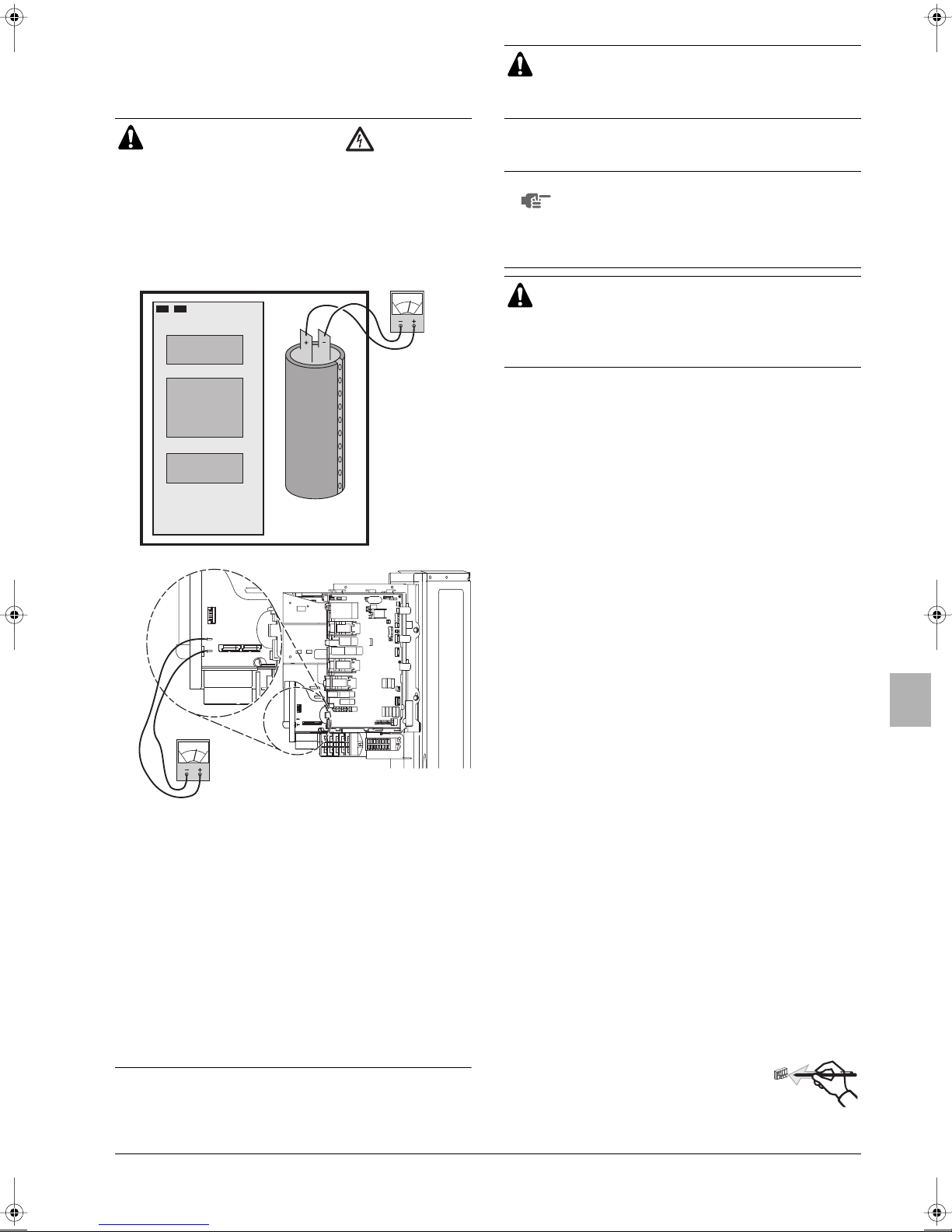
12. BEFORE OPERATION
12.1. Service precautions
Play it safe!
Touch a metal part by hand (such as the stop valve) in
order to eliminate static electricity and to protect the PCB
before performing service.
WARNING: ELECTRIC SHOCK
Caution when performing service to inverter equipment
■ Do not touch live parts for 10 minutes after the power supply is
turned off because of high voltage risk.
■ Additionally, measure the points as shown in the figure with a
tester and confirm that the voltage of the capacitor in the main
circuit is no more than 50 V DC.
DPQ
A1P
X106A X107A
A2P
A4P
X2M
A1P
XPQ
C+
C–
■ Make sure that the power supply is turned off before performing
the maintenance work. The heater of the compressor may
operate even in stop mode.
■ Please note that some sections of the electric component box
are extremely hot.
■ In order to prevent damage to the PCB, first eliminate static
electricity by touching a metal part (e.g. stop valve) with your
hand. Then pull out the connector.
■ After measuring the residual voltage, pull out the outdoor fan
connector.
■ Make sure you do not touch a conductive section.
■ The outdoor fan may rotate due to strong backblow wind,
causing the capacitor to charge. This may result in an electric
shock.
After maintenance, make sure the outdoor fan connector is
connected again. Otherwise, the unit may break down.
12.2. Checks before initial start-up
NOTE
After the installation, check the following before switching on the
circuit breaker:
1 Transportation stay
2 The position of the switches that require an initial setting
3 Power supply wiring and transmission wiring
4 Pipe sizes and pipe insulation
5 Additional refrigerant charge
6 Insulation test of the main power circuit
7 Stop valves
8 Drain pipe installation
Note that during the first running period of the unit,
required power input may be higher than stated on the
nameplate of the unit. This phenomenon originates
from the compressor that needs elapse of a 50 hours
run in period before reaching smooth operation and
stable power consumption.
■ Make sure that the circuit breaker on the power supply
panel of the installation is switched off.
■ Attach the power wire securely.
■ Introducing power with a missing N-phase or with a
mistaken N-phase will break the equipment.
Be sure that the transportation stay is removed from the
compressor.
Make sure that switches are set according to your application
needs before turning the power supply on.
Use a designated power supply and transmission wiring and
make sure that it has been carried out according to the
instructions described in this manual, according to the wiring
diagrams and according to local and national regulations.
Make sure that correct pipe sizes are installed and that the
insulation work is properly executed.
The amount of refrigerant to be added to the unit should be
written on the included "Added Refrigerant" plate and attached
to the rear side of the front cover.
Using a megatester for 500 V, check that the insulation
resistance of 2 MΩ or more is attained by applying a voltage of
500 V DC between power terminals and earth. Never use the
megatester for the transmission wiring.
Be sure that the stop valves are open on both liquid and gas
side.
Make sure that the drain piping is installed properly.
12.3. Field setting
If required, carry out any field setting according to the following
instructions. Refer to the service manual for more details.
Handling the switches
When carrying out field settings, operate the
switches with an insulated stick (such as a ballpoint pen) to avoid touching of live parts.
U-4~6ML5DPQ + U-4~6ML5XPQ
Urban Multi air conditioner
4PW40731-1
Installation manual
17
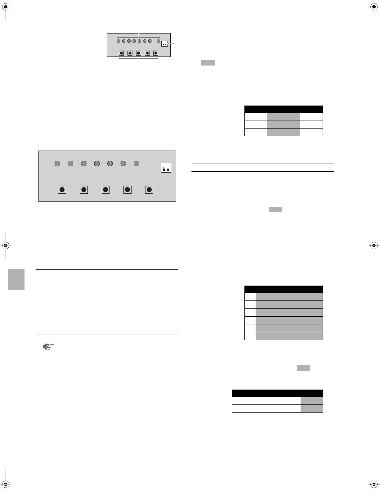
Location of the DIP switches, leds and buttons
Led H1P~H8P
1
Push button switches BS1~BS5
2
DIP switches 2 (DS1-1, DS1-2)
3
1
2
Setting mode 1
The H1P led is off (COOL/HEAT selection setting).
Setting procedure
3
1 Push the button and adjust the led indication to either
one of the possible settings as shown below in the field marked
BS2 SET
:
Led state
Throughout the manual the state of the leds is indicated as follows:
x
OFF
w
ON
c
blinking
Setting the push button switch (BS1~5)
Function of the push button switch which is located on the outdoor
unit PCB:
H1P H2P H3P H4P H5P H6P H7P
MODE
TEST/
IND MASTER SLAVE L.N.O.P. DEMAND
HWL
BS1
BS1 MODE
BS2 SET
BS3 RETURN
BS4 TEST
BS5 RESET
BS2
MODE SET RETURN TEST RESET
For changing the set mode
For field setting
For field setting
For test operation
For resetting the address when the wiring is changed or when
an additional indoor unit is installed
BS3
BS4
BS5
ON OFF
DS1 1 2
The figure shows state of the led indications when the unit is shipped
from the factory.
Setting the mode
The set mode can be changed with the button according
to the following procedure:
■ For setting mode 1: Press the button once, the led
is off x.
■ For setting mode 2: Press the button for
5 seconds, the H1P led is on w.
If the H1P led is blinking c and the button is pushed
once, it will change to setting mode 1.
NOTE
If you get confused in the middle of the setting
process, push the button. Then it returns to
setting mode 1 (H1P led is off).
BS1 MODE
BS1 MODE
BS1 MODE
BS1 MODE
BS1 MODE
1 In case of COOL/HEAT setting by each individual outdoor unit
circuit.
2 In case of COOL/HEAT setting by the master unit when outdoor
units are connected in multiple-system combination
3 In case of COOL/HEAT setting by the slave unit when outdoor
units are connected in multiple-system combination
H1P H2P H3P H4P H5P H6P H7P
xxc x xxx
1
xxx c xxx
2
xxx x cx x
3
(*) It is necessary to use the optional external control adapter for
outdoor unit (DTA104A61/62). See the instruction delivered with
the adapter.
2 Push the button and the setting is defined.
BS3 RETURN
(*)
.
(*)
.
Setting mode 2
The H1P led is on.
Setting procedure
1 Push the button according to the required function
(A~F). The led indication that matches the required function is
shown below in the field marked :
Possible functions
2 When the button is pushed, it indicates the current
setting.
3 Push the button according to the required setting
possibility as shown below in the field marked .
3.1 Possible settings for function A, B and F are (ON) or
(OFF).
BS2 SET
A additional refrigerant charging operation.
B refrigerant recovery operation/vacuuming operation.
C automatic low noise operation setting at nighttime.
D low noise operation level setting ( ) via the external
control adapter.
E power consumption limitation setting ( ) via the external
control adapter.
F enabling function of the low noise operation level setting
() and/or power consumption limitation setting
L.N.O.P
() via the external control adapter (DTA104A61/62).
DEMAND
H1P H2P H3P H4P H5P H6P H7P
w x w x w x x
A
w x w x w x w
B
w x w x w w x
C
w x w w x x w
D
w x w w w w x
E
w x x w w x x
F
BS3 RETURN
BS2 SET
H1P H2P H3P H4P H5P H6P H7P
w xxxxc x
ON
(*)
w xxxxx c
OFF
(*) This setting = factory setting.
L.N.O.P
DEMAND
ON
OFF
Installation manual
18
U-4~6ML5DPQ + U-4~6ML5XPQ
Urban Multi air conditioner
4PW40731-1
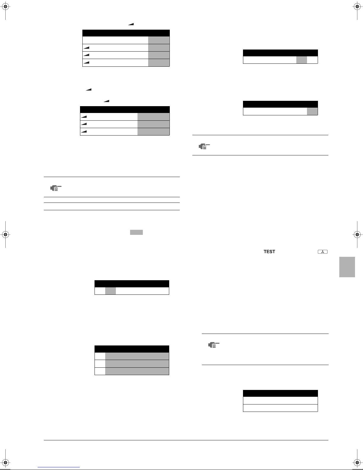
3.2 Possible settings for function C
The noise of level 3< level 2< level 1 ( ).
H1P H2P H3P H4P H5P H6P H7P
(*)
w xxxxx x
OFF
w xxxxx c
1
w xxxxc x
2
w xxxxc c
3
(*) This setting = factory setting.
3.3 Possible settings for function D and E
For function D ( ) only: the noise of level 3<
level 2< level 1 ( ).
For function E ( ) only: the power consumption of
level 1< level 2 < level 3 ( ).
(*) This setting = factory setting.
4 Push the button and the setting is defined.
5 When the button is pushed again, the operation
starts according to the setting.
Refer to the service manual for more details and for other settings.
NOTE
BS3 RETURN
BS3 RETURN
When finished, please mark the settings of function C,
D and E in the "Records" part of the label on the
backside of the front plate.
L.N.O.P
1
DEMAND
1
(*)
2
3
3
H1P H2P H3P H4P H5P H6P H7P
w xxxx x c
w xxxx c x
w xxxc x x
1
Confirmation of the set mode
The following items can be confirmed by setting mode 1 (H1P
led is off)
Check the led indication in the field marked .
1 Indication of the present operation state
normal
x
abnormal
w
under preparation or under test operation
c
H1P H2P H3P H4P H5P H6P H7P
x xwxxxx
2 Indication of COOL/HEAT selection setting
1 When set to COOL/HEAT change-over by each individual outdoor
unit circuit (= factory setting).
2 Indication on master unit when COOL/HEAT change-over is
carried out by outdoor units connected in multiple systemcombination.
3 Indication on slave unit when COOL/HEAT change-over is carried
out by outdoor units connected in multiple system-combination
H1P H2P H3P H4P H5P H6P H7P
(*)
x x w x x x x
1
x x x w x x x
2
x x x x w x x
3
(*) This setting = factory setting.
3 Indication of low noise operation state
standard operation (= factory setting)
x
w
L.N.O.P
operation
H1P H2P H3P H4P H5P H6P H7P
L.N.O.P
x xwx x xx
4 Indication of power consumption limitation setting
standard operation (= factory setting)
x
w
DEMAND
operation
H1P H2P H3P H4P H5P H6P H7P
DEMAND
xxwxxxx
12.4. Test operation
NOTE
■ Check the stop valves
■ After installation, perform the test operation.
Performing the test operation
1 To protect the compressor, make sure to turn on the power
2 Set to setting mode 1 (H1P led is off) (refer to "Setting mode 1"
3 Press the button for 5 seconds when the unit is at a
4 After the test operation (maximum 30 minutes), the unit
After turning on the power supply, the unit can not be
started until the H2P initialisation led goes off
(maximum 12 minutes).
Make sure to open the gas and liquid line stop valves.
Unless the test operation is performed, the error code "U3" is
shown on the remote controller and the unit cannot be operated.
supply 6 hours before starting operation.
on page 18).
NOTE
BS4 TEST
When you want to terminate the test operation,
press the button. The unit will keep
running for 30 seconds and then stops. During
test operation it is impossible to stop the unit with
the remote controller.
BS3 RETURN
standstill. The test operation starts when the H2P led blinks and
the remote controller indicates (test operation) and
(external control).
It may take 10 minutes to bring the state of refrigerant uniform
before the compressor starts, but that is not a malfunction.
The test operation is automatically carried out in cooling mode
during 15~30 minutes.
Depending on the situation, the refrigerant running sound or the
sound of a magnetic solenoid valve may rise during this
operation.
The following items are automatically checked:
- Check for incorrect wiring
- Check if stop valves are open
- Check of refrigerant charge
-Automatic judgement of piping length
automatically stops. Check the operation results by the outdoor
unit led indication.
U-4~6ML5DPQ + U-4~6ML5XPQ
Urban Multi air conditioner
4PW40731-1
normal
abnormal
H1P H2P H3P H4P H5P H6P H7P
xxwxxxx
xwxxxxx
Installation manual
19
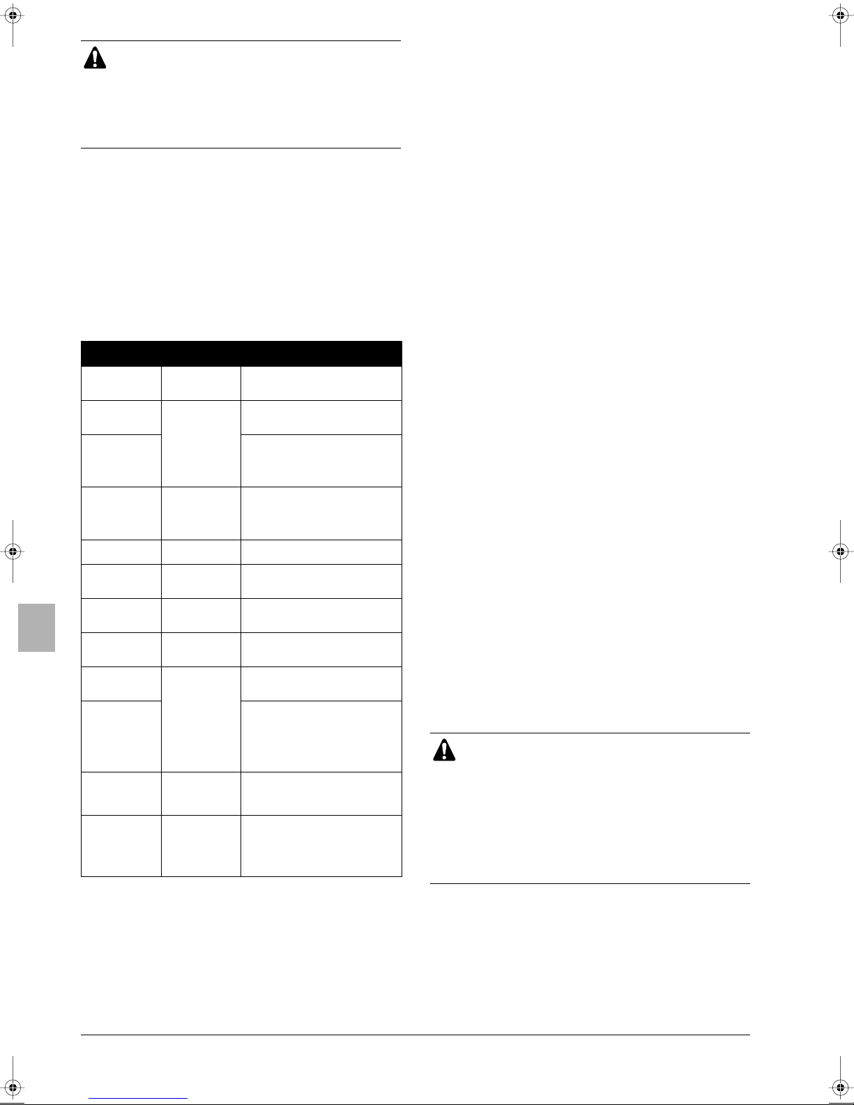
■ Indoor units cannot be checked individually. After the
test operation is finished, check the indoor units
individually via the remote controller.
■ The led indication changes during this operation, but
that is not abnormal.
■ Please attach the front plate of the outdoor unit in
order to prevent electric shocks.
5 Measure to be taken when operation finishes abnormally
1. Confirm the error code on the remote controller.
2. Correct what is abnormal.
(See the installation manual and operation manual or contact
your dealer.)
3. After the abnormality is corrected, press the
BS3 RETURN
button and reset the error code.
4. Start the unit again to confirm that the problem is properly
solved.
5. If no error code is indicated on the remote controller, it is
possible to start operation after 5 minutes.
Error codes on the remote controller
Malfunction
Installation error
The stop valve of
an outdoor unit is
left closed.
The stop valve of
an outdoor unit is
left closed.
Insufficient
refrigerant
Refrigerant
overcharge
Insufficient supply
voltage
The check
operation is not
performed.
No power is
supplied to the
outdoor unit.
Improper type of
indoor units are
connected.
The stop valve of
an outdoor unit is
left closed.
The piping and
wiring of the
specified indoor
unit are not
connected
correctly to the
outdoor unit.
Incorrect
interconnections
between units.
Power supply
cables are
connected in the
reverse phase
instead of the
normal phase.
code
E3
E4
F3
E3
F6
U2
U3
U4
UA
UF
UH
U1
Remedial action
Open the stop valve on both the gas
and liquid side.
Open the stop valve on both the gas
and liquid side.
Check if the additional refrigerant
charge has been finished correctly.
Recalculate the required amount of
refrigerant from the piping length and
add an adequate amount of refrigerant.
Recalculate the required amount of
refrigerant from the piping length and
correct the refrigerant charge level by
recovering any excessive refrigerant
with a refrigerant recovery machine.
Check if the supply voltage is supplied
properly.
Perform the check operation.
Check if the power wiring for the
outdoor unit is connected correctly.
Check the type of indoor units that are
currently connected. If they are not
proper, replace them with proper ones.
Open the stop valve on both the gas
and liquid side.
Confirm that the piping and wiring of the
specified indoor unit are connected
correctly to the outdoor unit.
Connect correctly the interconnections
between units to the F1 and F2 (TO
IN/D UNIT) terminals on the PC board
in the outdoor unit.
Connect the power supply cables in
normal phase. Change any two of the
three power supply cables (L1, L2, L3)
to correct phase.
12.5. Checks in normal operation
Set the master unit (= indoor unit having the right to select the
cooling/heating operation mode).
In case of wired remote controllers
■ After the check operation, "CHANGEOVER UNDER CONTROL"
is blinking in all connected remote controllers.
■ Select an indoor unit to be used as the master unit in
accordance with the request from the customer.
(It is recommended to select an indoor unit which will be used
most often as the master unit.)
■ Press the operation mode selector button in the remote
controller of the indoor unit selected as the master unit.
■ In that remote controller, "CHANGEOVER UNDER CONTROL"
disappears. That remote controller will control changeover of the
cooling/heating operation mode.
■ In other remote controllers, "CHANGEOVER UNDER
CONTROL" lights up.
In case of wireless remote controllers
■ After the check operation, the timer lamp is blinking in all
connected indoor units.
■ Select an indoor unit to be used as the master unit in
accordance with the request from the customer.
(It is recommended to select an indoor unit which will be used
most often as the master unit.)
■ Press the operation selector mode button in the remote
controller of the indoor unit selected as the master unit. A "peep"
sound is issued, and the timer lamp turns off in all indoor units.
■ That indoor unit will control changeover of the cooling/heating
operation mode.
For the details, refer to the instruction manual supplied together
with the indoor unit.
12.6. Temperature adjustment operation confirmation
After the test run is over, operate the unit normally. (Heating is not
possible if the outdoor temperature is 24°C or higher.)
■ Make sure the indoor and outdoor units are operating normally
(If a knocking sound can be heard in the liquid compression of
the compressor, stop the unit immediately and then energize the
heater for a sufficient length of time before restarting the
operation.)
■ Run each indoor unit one at a time and make sure the
corresponding outdoor unit is also running.
■ Check to see if cold (or hot) air is coming out of the indoor unit.
■ Press the fan direction and fan strength buttons on the indoor
unit to see if they operate properly.
Cautions for normal operation check
■ Once stopping, the compressor will not restart in
about 5 minutes even if the Run/Stop button of an
indoor unit in the same system is pressed.
■ When the system operation is stopped by the remote
controller, the outdoor units may continue operating
for a further 1 minute maximum.
■ After the test run, when handling the unit over to the
customer, make sure the electric box lid, the service
lid and the unit casing are all attached properly.
Installation manual
20
U-4~6ML5DPQ + U-4~6ML5XPQ
Urban Multi air conditioner
4PW40731-1
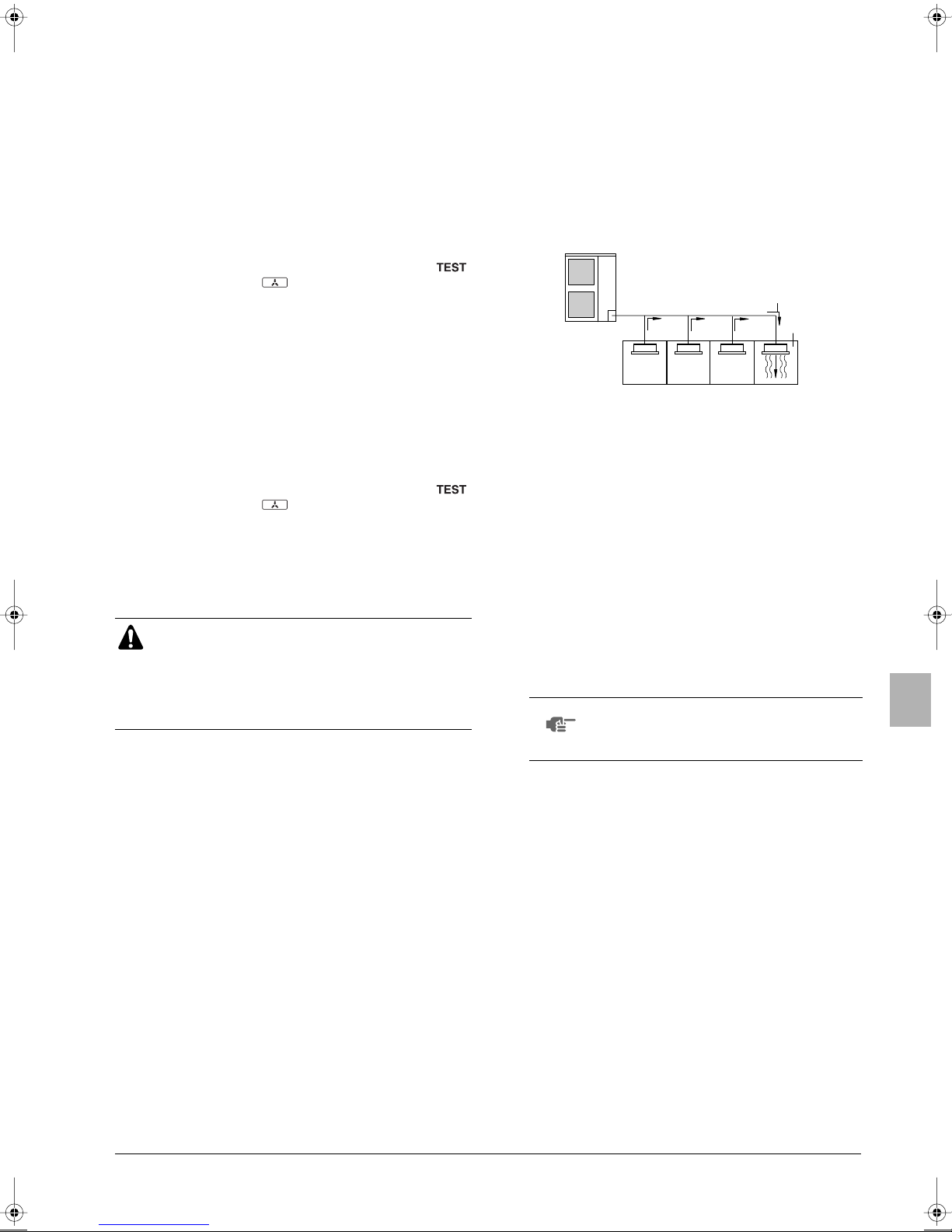
13. SERVICE MODE OPERATION
2
1
After turning on the power supply, the unit can not be started until the
H2P initialisation led, indicating that the unit is still under preparation,
goes off (maximum 12 minutes).
Vacuuming method
At the first installation, this vacuuming is not required. It is required
only for repair purposes.
1 When the unit is at a standstill and under the setting mode 2, set
the required function B (refrigerant recovery operation/
vacuuming operation) to (ON).
- After this is set, do not reset the setting mode 2 until the
vacuuming is finished.
- The H1P led is on and the remote controller indicates
(test operation) and (external control) and the
operation will be prohibited.
2 Vacuum the system with a vacuum pump.
ON
14.2. Maximum concentration level
The maximum charge of refrigerant and the calculation of the
maximum concentration of refrigerant is directly related to the
humanly occupied space in to which it could leak.
The unit of measurement of the concentration is kg/m
kg of the refrigerant gas in 1 m
Compliance to the local applicable regulations and standards for the
maximum allowable concentration level is required.
According to the appropriate European Standard, the maximum
allowed concentration level of refrigerant to a humanly space for
R410A is limited to 0.44 kg/m
3
volume of the occupied space).
3
.
3
(the weight in
3 Press the button and reset the setting mode 2.
Refrigerant recovery operation method by a refrigerant
reclaimer.
1 When the unit is at a standstill and in setting mode 2, set the
required function B (refrigerant recovery operation/vacuuming
operation) to (ON).
- The indoor unit and the outdoor unit expansion valves will
- The H1P led is on and the remote controller indicates
2 Recover the refrigerant using a refrigerant reclaimer. For details,
see the operation manual delivered with the refrigerant
reclaimer.
3 Press the button and reset the setting mode 2.
BS1 MODE
ON
fully open and some solenoid valves will open.
(test operation) and (external control) and the
operation will be prohibited.
BS1 MODE
CAUTION
Never turn the power of the outdoor unit OFF while the
refrigerant is being recovered.
If the power is turned OFF, the solenoid valves are closed
and the refrigerant cannot be recovered from the outdoor
unit.
14. CAUTION FOR REFRIGERANT LEAKS
(Points to note in connection with refrigerant leaks.)
1 direction of the refrigerant flow
2 room where refrigerant leak has occurred (outflow of all the
refrigerant from the system)
Pay special attention to places, such as a basements, etc. where
refrigerant can stay, since refrigerant is heavier than air.
14.3. Procedure for checking maximum concentration
Check the maximum concentration level in accordance with steps 1
to 4 below and take whatever action is necessary to comply.
1 Calculate the amount of refrigerant (kg) charged to each system
separately.
amount of refrigerant
in a single unit
system (amount of
refrigerant with
which the system is
charged before
leaving the factory)
NOTE
Where a single refrigerant facility is divided into
2 entirely independent refrigerant systems, use
the amount of refrigerant with which each
separate system is charged.
additional charging
amount (amount of
+
refrigerant added
locally in accordance
with the length or
diameter of the
refrigerant piping)
=
total amount of
refrigerant (kg)
in the system
14.1. Introduction
The installer and system specialist shall secure safety against
leakage according to local regulations or standards. The
following standards may be applicable if local regulations are
not available.
The Urban Multi System, like other air conditioning systems, uses
R410A as refrigerant. R410A itself is an entirely safe non-toxic, noncombustible refrigerant. Nevertheless care must be taken to ensure
that air conditioning facilities are installed in a room which is
sufficiently large. This assures that the maximum concentration level
of refrigerant gas is not exceeded, in the unlikely event of major leak
in the system and this in accordance to the local applicable
regulations and standards.
U-4~6ML5DPQ + U-4~6ML5XPQ
Urban Multi air conditioner
4PW40731-1
Installation manual
21
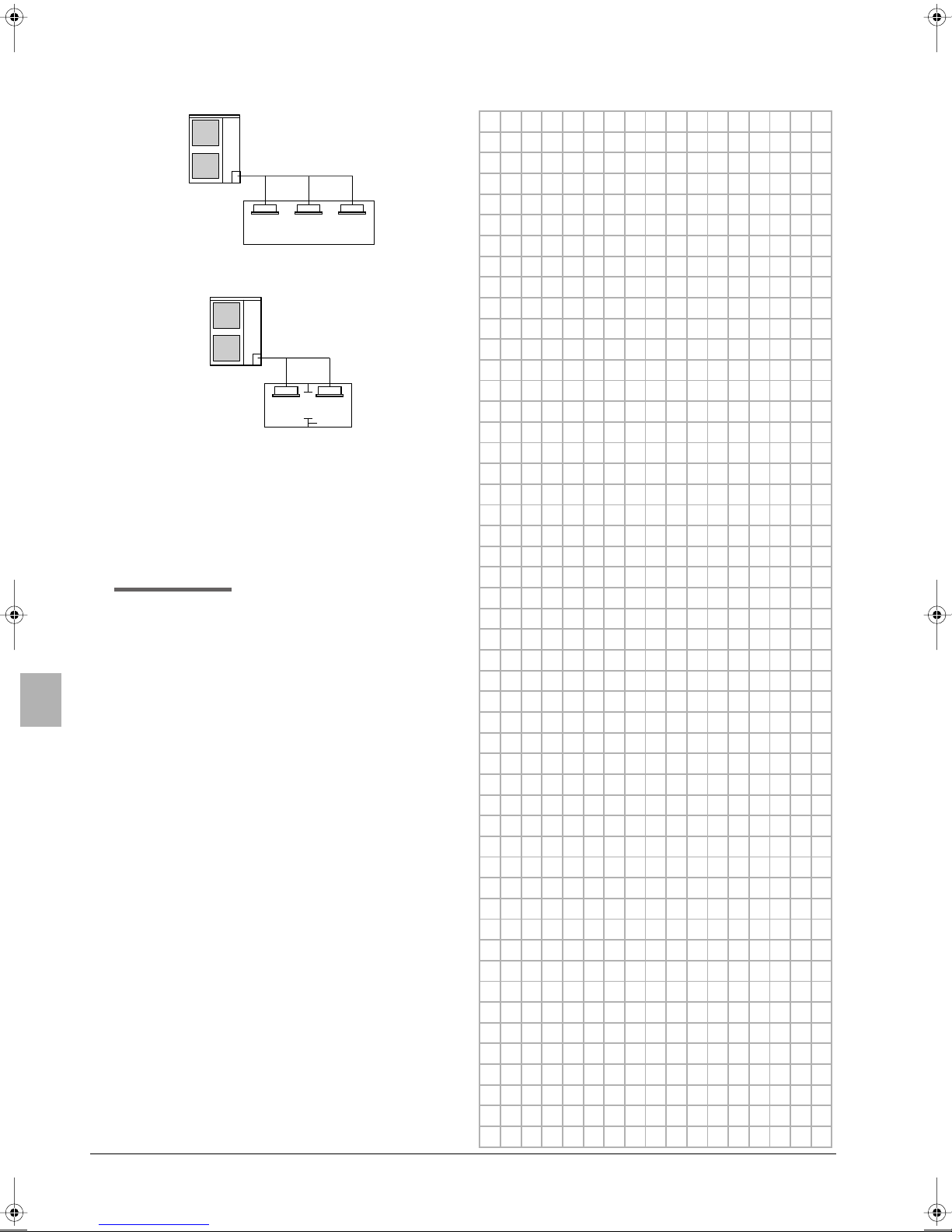
2 Calculate the smallest room volume (m3)
In a case such as the following, calculate the volume of (A), (B)
as a single room or as the smallest room.
A. Where there are no smaller room divisions
B. Where there is a room division but there is an
opening between the rooms sufficiently large to
permit a free flow of air back and forth.
1
2
1 opening between rooms
2 partition
(Where there is an opening without a door or where there
are openings above and below the door which are each
equivalent in size to 0.15% or more of the floor area.)
3 Calculating the refrigerant density using the results of the
calculations in steps 1 and 2 above.
total volume of
refrigerant in the
refrigerant system
3
) of smallest
size (m
room in which there is
an indoor unit installed
If the result of the above calculation exceeds the maximum
concentration level then make similar calculations for the second
then third smallest room and so until the result falls short of the
maximum concentration.
4 Dealing with the situations where the result exceeds the
maximum concentration level.
Where the installation of a facility results in a concentration in
excess of the maximum concentration level then it will be
necessary to revise the system.
Please consult your supplier.
maximum concentration level (kg/m3)
≤
NOTES
15. DISPOSAL REQUIREMENTS
Dismantling of the unit, treatment of the refrigerant, of oil and of other
parts must be done in accordance with relevant local and national
legislation.
Installation manual
22
U-4~6ML5DPQ + U-4~6ML5XPQ
Urban Multi air conditioner
4PW40731-1
U-4ML5DPQ U-4ML5XPQ
U-5ML5DPQ U-5ML5XPQ
U-6ML5DPQ U-6ML5XPQ
Urban Multi Klimaanlage
Installationsanleitung
INHALTSVERZEICHNIS Seite
1. Sicherheitsaspekte.....................................................................1
2. Einleitung ................................................................................... 2
2.1. Kombination ................................................................................... 2
2.2. Standardzubehör ............................................................................ 3
2.3. Sonderzubehör ............................................................................... 3
2.4. Technische und elektrische Daten ................................................. 3
3. Vor der Installation.....................................................................3
3.1. Vorsichtsmaßnahmen für R410A ................................................... 3
3.2. Installation ...................................................................................... 3
3.3. Handhabung ................................................................................... 3
4. Auswahl des Aufstellungsortes ..................................................3
5. Vorsichtsmaßnahmen bei der Installation.................................. 4
5.1. Installationsmethode zur Verhinderung des Umstürzens
der Anlage......................................................................................5
5.2. Vorgehensweise zur Entfernung der Transportstütze .....................5
5.3. Verfahren zur Installation der Kondensatleitung............................. 5
6. Platzbedarf für die Installation....................................................5
7. Durchmesser und maximal zulässige Länge der
Kältemittelleitung........................................................................6
7.1. Auswahl der Rohrleitungsmaterialien ............................................. 6
8. Vorsichtsmaßnahmen bei Kältemittelleitungen.......................... 7
8.1. Vorsichtsmaßnahmen bei Lötarbeiten............................................7
8.2. Warnhinweise zu Bördelanschlüssen.............................................7
9. Kältemittelleitungen....................................................................8
9.1. Verhindern des Eindringens von Fremdstoffen ..............................8
9.2. Vorsichtsmaßnahmen bei der Handhabung von Absperrventilen ..8
9.3. Verwendung des Absperrventils..................................................... 9
9.4. Warnhinweise zur Handhabung der Ventilabdeckung.................... 9
9.5. Warnhinweise zur Handhabung der Wartungsöffnung...................9
9.6. Vorsichtsmaßnahmen beim Anschließen
bauseitiger Leitungen und im Hinblick auf die Isolierung ............... 9
9.7. Dichtheitsprobe und Vakuumtrocknung........................................ 11
10. Einfüllen von zusätzlichem Kältemittel..................................... 11
10.1. Wichtige Informationen hinsichtlich des verwendeten
Kältemittels................................................................................... 12
10.2. 3 Vorgehensweisen für das Hinzufügen von Kältemittel...............12
11. Elektrische Anschlüsse............................................................14
11.1. Innenverkabelung - Teileübersicht ................................................ 14
11.2. Vorsichtsmaßnahmen bei Verkabelungsarbeiten......................... 16
11.3. Anschlussbeispiel des gesamten Verkabelungssystems .............16
11.4. Anschluss des Stromkabels und der Übertragungskabel ............ 16
11.5. Anforderungen an Stromkreis und Stromkabel ............................ 17
12. Vor der Inbetriebnahme ........................................................... 18
12.1. Wartungsvorsichtsmaßnahmen.................................................... 18
12.2. Kontrollen vor der erstmaligen Inbetriebnahme............................19
12.3. Bauseitige Einstellung..................................................................19
12.4. Probelauf......................................................................................21
12.5. Überprüfungen bei Normalbetrieb................................................22
12.6. Bestätigung des Temperatureinstellvorgangs............................... 22
13. Betrieb des Wartungsmodus....................................................22
14. Zur Beachtung bei austretendem Kältemittel........................... 23
14.1. Einführung....................................................................................23
14.2. Höchstwerte für die Konzentration ............................................... 23
14.3. Verfahren zur Prüfung der Höchstkonzentration ..........................23
15. Vorschriften zur Entsorgung.....................................................23
LESEN SIE SICH DIESE ANLEITUNG SORGFÄLTIG
VOR DER INSTALLATION DURCH. BEWAHREN SIE
DIESE ANLEITUNG GRIFFBEREIT AUF, DAMIT SIE
AUCH SPÄTER NOCH DARIN NACHSCHLAGEN
KÖNNEN.
UNSACHGEMÄSSE INSTALLATION ODER SICHERUNG
DER EINHEIT ODER DER ZUBEHÖRTEILE KANN ZU
ELEKTRISCHEM SCHLAG, KURZSCHLUSS,
AUSLAUFEN VON FLÜSSIGKEIT, BRAND ODER
ANDEREN SCHÄDEN FÜHREN. VERWENDEN SIE NUR
ZUBEHÖRTEILE VON PANASONIC, DIE SPEZIELL FÜR
DIE AUSRÜSTUNG ENTWICKELT WURDEN, UND
LASSEN SIE SIE VON EINEM FACHMANN
INSTALLIEREN.
PANASONIC DIE AUSRÜSTUNG IST FÜR KOMFORTZWECKE KONSTRUIERTWORDEN. FÜR DEN
GEBRAUCH IN BEZUG AUF ANDERE ANWENDUNGEN,
NEHMEN SIE BITTE KONTAKT AUF MIT IHREM
ÖRTLICHEN PANASONIC HÄNDLER.
SOLLTEN FRAGEN ZUM INSTALLATIONSVERFAHREN
ODER ZUR INBETRIEBNAHME AUFTRETEN, WENDEN
SIE SICH BITTE AN IHREN HÄNDLER. VON IHM
ERHALTEN SIE DIE NOTWENDIGEN RATSCHLÄGE
UND INFORMATIONEN.
DIESE KLIMAANLAGE FÄLLT UNTER DIE KLAUSEL
"GERÄTE NICHT ZUGÄNGLICH FÜR DIE
ALLGEMEINHEIT".
1. SICHERHEITSASPEKTE
In diesem Dokument werden die folgenden beiden Warnhinweistypen verwendet. Beide beziehen sich auf sehr wichtige Punkte;
daher sollten Sie sie unbedingt beachten.
WARNUNG
Wird ein Warnhinweis missachtet, kann dies schwerwiegende Folgen für
Leib und Leben zur Folge haben.
VORSICHT
Wird der jeweilige Vorsichthinweis nicht beachtet, kann dies
Verletzungen oder eine Beschädigung der Ausrüstung zur Folge haben.
Warnung
■ Bitten Sie Ihren Händler oder qualifiziertes Fachpersonal, die
Anlage zu installieren. Installieren Sie die Anlage auf keinen Fall
allein.
Eine falsche oder unsachgemäße Installation kann austretendes
Wasser, elektrische Schläge oder Brände zur Folge haben.
■ Führen Sie sämtliche Installationsarbeiten gemäß den
Anleitungen in dieser Installationsanleitung durch.
Eine falsche oder unsachgemäße Installation kann austretendes
Wasser, elektrische Schläge oder Brände zur Folge haben.
■ Wenn eine Einheit in einem kleinen Raum installiert wird,
müssen entsprechende Vorkehrungen getroffen werden, dass
die Menge des bei einem Leck austretenden Kältemittels nicht
die maximal zulässige Menge übersteigt. Informationen zu
diesen Vorkehrungen zum Verhindern von Lecks erhalten Sie
bei Ihrem Händler.
Wenn die ausgetretene Menge das maximal zulässig Limit
übersteigt, kann dies Unfälle durch Sauerstoffmangel zur Folge
haben.
U-4~6ML5DPQ + U-4~6ML5XPQ
Urban Multi Klimaanlage
4PW40731-1
Installationsanleitung
1
■ Verwenden Sie daher ausschließlich die angegebenen Zubehörteile und Komponenten bei der Installation der Anlage.
Werden andere nicht spezifizierte Komponenten verwendet,
kann dies Wasserverlust, elektrische Schläge, Brände oder ein
Umkippen der Anlage zur Folge haben.
■ Installieren Sie die Klimaanlage auf einem Untergrund, der ihr
Gewicht mühelos tragen kann.
Ist dies nicht der Fall, kann die Anlage umkippen, was wiederum
Ver letzungen zur Folge haben kann.
■ Berücksichtigen Sie bei der Installation, dass starke Winde,
Orkane sowie Erdbeben auftreten können.
Wurde die Anlage unsachgemäß installiert, kann sie umkippen
bzw. umgeworfen werden, was zu unvorhergesehenen Unfällen
führen kann.
■ Stellen Sie sicher, dass die gesamte Elektrik von einem qualifizierten Fachmann gemäß den jeweils geltenden Vorschriften
und gemäß den Informationen in dieser Installationsanleitung
installiert und an einen separaten Stromkreis angeschlossen
wird.
Ein Stromkreis mit unzureichender Kapazität oder eine unsachgemäß installierte Elektrik kann zu elektrischem Schlag oder zu
Bränden führen.
■ Stellen Sie daher sicher, dass sämtliche Kabel ordnungsgemäß
und sicher angeschlossen und nicht zu straff sind und dass
keine externen Kräfte darauf einwirken können.
Eine unvollständige Verkabelung oder nicht ordnungsgemäß
angeschlossene Kabel können Brände zur Folge haben.
■ Beim Verlegen der Verkabelung zwischen den Innen- und
Außengeräten sowie beim Anschließen der Stromversorgung
müssen die Kabel so verlegt werden, dass die Frontblende ohne
Probleme angebracht werden kann.
Wenn diese Frontblende nicht passend angebracht wird, kann
dies eine Überhitzung der Anschlussklemmen, elektrischen
Schlag oder Brände zur Folge haben.
■ Sollte während der Installationsarbeiten Kältemittelgas austreten, muss der Raum sofort entlüftet werden.
Wenn Kältemittelgas in Kontakt mit Flammen kommt, kann dies
giftige Gase erzeugen.
■ Stellen Sie nach Abschluss der Installationsarbeiten sicher,
dass nirgendwo Kältemittelgas austritt.
Es können giftige Gase erzeugt werden, wenn Kältemittelgas in
den Raum austritt und mit Flammen (z.B. Heizlüfter, Ofen oder
Kocher) in Kontakt kommt.
■ Schalten Sie die Stromzufuhr über den Hauptschalter aus, bevor
Sie die elektrischen Anschlussklemmen berühren.
Vorsicht
■ Schließen Sie die Klimaanlage an Masse an.
Der Erdungswiderstand muss den nationalen Vorschriften
entsprechen.
Schließen Sie das Erdungskabel weder an Gas- und
Wasserleitungen noch an Blitzableiter oder das
Erdungskabel Ihres Telefons an.
Ist die Anlage nur unzureichend geerdet, kann es zu
elektrischem Schlag kommen.
■ Gasleitung
Im Fall von Gaslecks kann es zu Verpuffungen oder
Explosionen kommen.
■ Wasserleitung.
Harte Vinylschläuche bieten nicht genügend Erdungspotenzial.
■ Blitzableiter oder Telefonerdungskabel.
Das elektrische Potenzial kann drastisch anzeigen, wenn die
Anlage von den Auswirkungen eines Blitzeinschlags
betroffen ist.
■ Installieren Sie unbedingt einen Erdschlussdetektor.
Wird dieser Unterbrecher nicht installiert, kann dies zu
elektrischem Schlag oder Brand führen.
■ Installieren Sie Kondensatleitungen gemäß den Anleitungen in
dieser Installationsanleitung, um das effiziente Ablaufen von
Kondensatwasser zu gewährleisten, und isolieren Sie diese
Leitungen, um Kondensatbildung zu verhindern.
Bei unsachgemäß installierten Kondensatleitungen kann
Wasser austreten, das beispielsweise ihre Möbel beschädigen
könnte.
■ Installieren Sie die Innen- und Außengeräte sowie das
Netzanschluss- und Verbindungskabel mindestens 1 Meter von
Fernsehgeräten oder Radios entfernt, um Interferenzen und
Rauschen zu vermeiden.
(Abhängig von den jeweiligen Radiowellen ist ein Abstand von
1 Meter möglicherweise nicht ausreichend.)
■ Spülen Sie die Außeneinheit nicht ab.
Dies kann elektrischen Schlag oder Brand verursachen.
■ Installieren Sie die Klimaanlage möglichst nicht an den
folgenden Plätzen bzw. Orten:
■ Räume mit einem Vorkommen an Mineralöl, Öldampf oder
Ölspritzern (z.B. Küchen).
Kunststoffteile könnten beschädigt werden, was zu deren
Unbrauchbarkeit oder zu Wasserlecks führen kann.
■ An Orten, an denen ätzende Gase wie Schwefelsäuregas
auftreten.
Das Korrodieren von Kupferleitungen und Lötteilen kann
austretendes Kältemittel zur Folge haben.
■ An Orten mit Geräten oder Maschinen, die elektro-
magnetische Wellen abstrahlen.
Elektromagnetische Wellen können das Steuerungssystem
stören, was einen Ausfall der Anlage zur Folge haben kann.
■ An Orten, an denen entflammbare Gase austreten, an denen
sich Kohlefasern oder entzündbarer Staub in der Luft
befinden oder an denen mit flüchtigen und/oder entflammbaren Gasen wie Verdünnern oder Benzin gearbeitet wird.
Diese Gase können einen Brand verursachen.
■ Orte mit stark salzhaltiger Umgebungsluft (z.B. in Meeres-
nähe).
■ In Umgebungen, in denen starke Spannungsschwankungen
auftreten (z.B. in Fabriken).
■ In Fahrzeugen oder auf Schiffen.
■ In Räumen, in denen säurehaltige oder alkalische Dämpfe
vorhanden sind.
■ Erlauben Sie es nicht, dass ein Kind an der Außeneinheit
hochsteigt oder vermeiden Sie das Ablegen von Gegenständen
auf der Einheit.
Fallen oder Sturz kann Verletzungen verursachen.
■ Berühren Sie kein Kältemittel, das aus den KältemittelRohranschlüssen ausgelaufen ist.
Dies kann Frostbeulen verursachen.
2. EINLEITUNG
2.1. Kombination
Die Innengeräte können in folgenden Baureihen eingebaut werden.
■ Verwenden Sie immer geeignete Inneneinheiten, die mit R410A
kompatibel sind.
Damit Sie wissen welche Modelle der Inneneinheiten mit R410A
kompatibel sind, beziehen Sie sich auf den Produktkatalog.
■ Gesamtkapazität/Menge der Inneneinheiten
Außeneinheit
U-4ML5 50~130 6
U-5ML5 62,5~162,5 8
U-6ML5 70~182 9
Gesamtkapazität
der Inneneinheiten
Gesamtmenge der
Inneneinheiten
Installationsanleitung
2
U-4~6ML5DPQ + U-4~6ML5XPQ
Urban Multi Klimaanlage
4PW40731-1
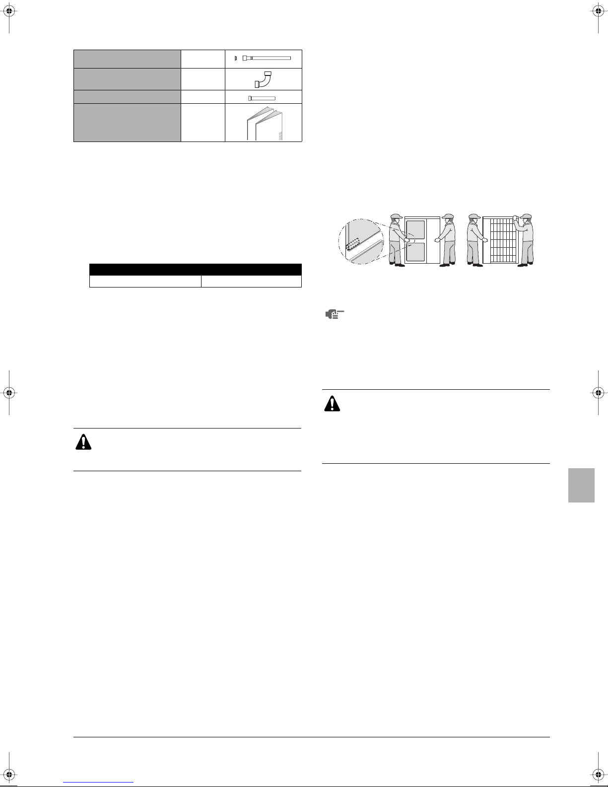
2.2. Standardzubehör
Gasleitungsrohr (1)
Kupferdichtung
Gasleitungsrohr (2)
Gasleitungsrohr (3)
Installationsanleitung
Betriebsanleitung
(*) Nur für U-6ML5.
Standort der Zubehörteile: siehe Abbildung 1.
1 Zubehör
(*)
+
(*)
(*)
1
1
1
1
1
+
2.3. Sonderzubehör
Um oben genannte Außeneinheiten zu installieren sind folgende
Zubehörteile erforderlich.
■ Kältemittel-Abzweigbausatz (nur für R410A: Verwenden Sie
immer einen geeigneten jeweiligen Satz für Ihr System).
Refnet-Verteiler Refnet-Abzweig
CZ-P29HK12Q CZ-P20BK12Q
Um einen optimalen Kältemittel-Abzweigbausatz auszuwählen,
beziehen Sie sich auf "Auswahl des Kältemittel-Abzweigbausatzes"
auf Seite 10.
3.2. Installation
■ Informationen zum Einbau von Innengeräten finden Sie in der
Installationsanleitung des jeweiligen Innengeräts.
■ Betreiben Sie die Klimaanlage niemals mit der demontierten
Thermistor-Entladung (R2T), Thermistor – Ansaugung (R3T)
und den demontierten Drucksensoren (S1NPH, S1NPL). Dieser
Vorgang kann den Kompressor durchbrennen.
■ Überprüfen Sie die Modellbezeichnungen und die
Seriennummern der äußeren Blenden (Frontblenden) beim
Anbringen/Abnehmen dieser Blenden, um Fehler zu vermeiden.
■ Achten Sie beim Schließen der Wartungsblenden darauf, dass
das Anziehdrehmoment 4,1 N•m nicht überschreitet.
3.3. Handhabung
Heben Sie die Anlage wie in der Abbildung gezeigt, an den Griffen
auf der linken und rechten Seite an, und bringen Sie sie in Position.
Positionieren Sie die Anlage, indem Sie sie an den Ecken anfassen.
Heben Sie sie auf keinen Fall am Saugeinlass an der Seite des
Gehäuses an, da dieses dadurch verformt werden könnte.
Achten Sie darauf, die Rippen auf der Rückseite nicht mit
den Händen oder mit Gegenständen zu berühren.
2.4. Technische und elektrische Daten
Die vollständigen technischen Daten sind dem technischen Datenbuch zu entnehmen.
3. VOR DER INSTALLATION
Da der Prüfdruck 4,0 MPa oder 40 bar beträgt, sind
eventuell Rohrleitungen mit einer größeren Wandstärke
erforderlich. Siehe auch "7.1. Auswahl der
Rohrleitungsmaterialien" auf Seite 6.
3.1. Vorsichtsmaßnahmen für R410A
■ Bei diesem Kältemittel sind strenge Vorsichtsmaßnahmen
erforderlich, damit das System sauber, trocken und dicht bleibt.
- Sauber und trocken
Fremdmaterialien (einschließlich Mineralöle oder Feuchtigkeit)
dürfen unter keinen Umständen in das System eindringen.
- Dicht
Lesen Sie sich sorgfältig das Kapitel "8. Vorsichtsmaßnahmen
bei Kältemittelleitungen" auf Seite 7 durch, und halten Sie sich
streng an die beschriebenen Verfahrensschritte.
■ Da es sich bei R410A um ein gemischtes Kältemittel handelt,
muss das erforderliche zusätzliche Kältemittel in flüssigem
Zustand eingefüllt werden. (Ist das Kältemittel in gasförmigem
Zustand, verändert sich seine Zusammensetzung, und das
System kann nicht korrekt arbeiten.)
■ Die angeschlossenen Innengeräte müssen speziell auf R410A
ausgelegt sein.
4. AUSWAHL DES AUFSTELLUNGSORTES
Dies ist ein Produkt der Klasse A. Dieses Produkt kann Funkstörungen in einer häuslichen Umgebung verursachen. In diesem
Fall muss der Anwender entsprechende Maßnahmen vornehmen.
■ Achten Sie darauf entsprechende Maßnahmen zu
ergreifen, um zu verhindern, dass die Außeneinheit
von Kleintieren als Unterschlupf verwendet wird.
■ Kleintiere, die in Kontakt mit Elektroteilen kommen,
können Funktionsstörungen, Rauch oder Brand
verursachen. Weisen Sie den Kunden darauf hin, den
Bereich um die Einheit sauber zu halten.
1 Wählen Sie einen Aufstellungsort, der die folgenden
Vor aussetzungen erfüllt und von Ihrem Kunden genehmigt
worden ist.
- Gut belüftete Plätze.
- Plätze, an denen die Anlage keine Nachbarn belästigen
kann.
- Plätze, die dem Gewicht und den Vibrationen der Anlage
mühelos standhalten und an denen die Anlage auf ebener
Fläche aufgestellt werden kann.
-Orte, an denen weder entflammbare Gase austreten noch
andere Stoffe auslaufen können.
- Plätze, an denen ausreichend Freiraum für die Wartung der
Anlage vorhanden ist.
- Plätze, an denen die Rohrleitungen und Kabel der Innenund Außengeräte die zulässige Länge weder über- noch
unterschreiten.
-Orte, an denen aus der Einheit auslaufendes Wasser keinen
Schaden anrichten kann (z.B. im Falle eines verstopften
Abflussrohrs).
- Plätze, die vor unmittelbaren Niederschlägen geschützt sind.
U-4~6ML5DPQ + U-4~6ML5XPQ
Urban Multi Klimaanlage
4PW40731-1
Installationsanleitung
3
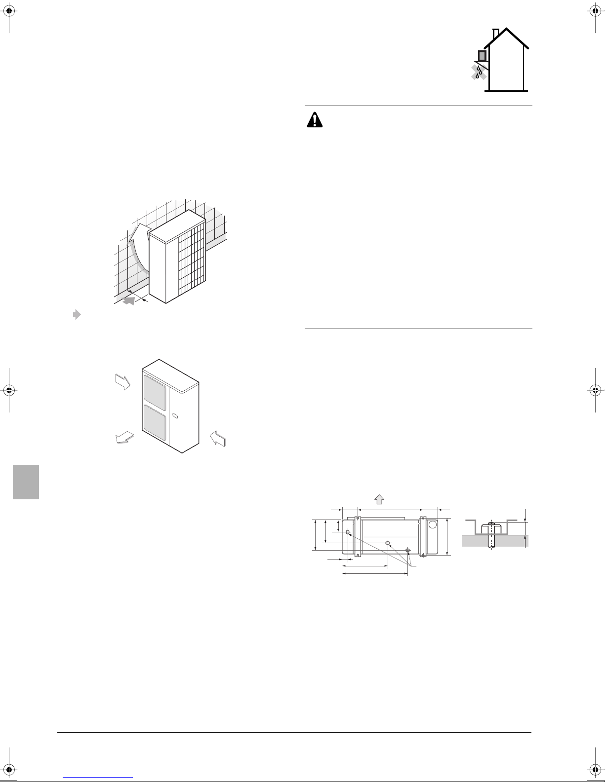
2 Bei Installation der Einheit an einem sehr windigen Ort sind
folgende Punkte zu beachten.
Starke Winde von 5 m/Sek. oder mehr, die von außen gegen
den Luftauslass des Außengeräts blasen (ausgeblasene Luft
wird herausgesaugt), können einen Kurzschluss verursachen,
was folgende Konsequenzen haben kann:
-Verminderte Betriebskapazität.
- Häufige Frostbildung während des Heizbetriebs.
- Betriebsunterbrechung aufgrund zu hohen Drucks.
- Bei starkem Wind, der kontinuierlich gegen die Vorderseite
des Geräts bläst, kann der Ventilator so stark beschleunigt
werden, dass er bricht.
Siehe die Abbildungen, die die Aufstellung dieser Einheit an
einem Platz mit vorhersehbarer Windrichtung zeigen.
■ Stellen Sie die Einheit so auf, dass die Luftauslassseite einer
Gebäudewand, einem Zaun oder einer Windschutzwand
zugewandt ist.
Stellen Sie sicher, dass ausreichend Platz für die Aufstellung
der Einheit vorhanden ist.
■ Richten Sie die Luftauslassseite im korrekten Winkel zur
Windrichtung aus.
Starker Wind
Ausgeblasene
Luft
Starker Wind
3 Legen Sie einen Wasserablaufkanal rings um das Fundament
an, damit Abwasser von der Einheit ablaufen kann.
4 Wenn der Wasserablauf der Einheit ein Problem darstellt,
installieren Sie die Einheit auf einem Fundament aus
Betonblöcken o.ä. (maximale Höhe des Fundaments: 150 mm).
5 Wenn Sie die Einheit auf einem Gestell installieren, bringen Sie
unter der Einheit in einem Abstand von maximal 150 mm eine
wasserdichte Platte an, damit das Wasser nicht von unten
eindringen kann.
6 Bei Installation der Einheit an einem Ort mit häufigem
Schneefall sind folgende Punkte zu beachten:
- Sorgen Sie dafür, dass die Standfläche der Anlage so hoch
wie möglich ist.
- Bauen Sie ein großes Vordach (bauseitig).
- Entfernen Sie das Ansauggitter auf der Rückseite der
Einheit, um zu vermeiden, dass sich Schnee auf den Rippen
ansammelt.
7 Die Außeneinheit kann abhängig von ihrer Umgebung einen
Kurzschluss erzeugen, verwenden Sie deshalb die
Luftleitbleche (bauseitig).
8 Wenn Sie die Einheit auf einem Einbau-
rahmen installieren, bringen Sie eine
wasserdichte Platte (in max. 150 mm
Abstand von der Unterseite der Einheit) an
oder verwenden Sie einen
Kondensatstopfen-Bausatz (Option), um
ein Heruntertropfen von Ablaufwasser zu
vermeiden.
Das in diesem Handbuch beschriebene Gerät kann
Elektrogeräusche verursachen, die von Radiofrequenz
erzeugt werden. Das Gerät entspricht den Spezifikationen,
die gemacht wurden um für ausreichenden Schutz gegen
solche Störungen zu sorgen. Es gibt jedoch keine
Garantie, dass eine Störung nicht bei einer
entsprechenden Installation auftritt.
Es ist deshalb empfehlenswert das Gerät und elektrische
Leitungen unter Einhaltung entsprechender Entfernungen
von Stereogeräten, Personalcomputer etc. zu installieren.
(Siehe Abbildung 2)
1 Personalcomputer oder Radio
2 Sicherung
3 Erdschlussanzeiger
4 Fernbedienung
5 Wahlschalter für Kühlen/Heizen
6 Innengerät
Bei extremen Verhältnissen, sollten Sie Entfernungen von
3 m oder mehr einhalten und Kabelkanal-Schutzrohre für
Strom- und Fernleitungen verwenden.
5. VORSICHTSMAßNAHMEN BEI DER
NSTALLATION
I
■ Überprüfen Sie die Stärke und Ebenheit der Aufstellungsfläche,
so dass die Einheit nach der Installation keine Vibrationen oder
Betriebslärm erzeugt.
■ Wie in der Abbildung gezeigt, ist die Einheit mit den dafür
vorgesehenen Ankerschrauben fest auf der Einbaufläche zu
verschrauben. (Halten Sie hierzu 4 Sätze M12-Ankerschrauben,
Muttern und Unterlegscheiben bereit, die überall erhältlich sind.)
■ Es empfiehlt sich, die Ankerschrauben nur so weit
einzuschrauben, dass noch 20 mm Schraubenlänge über der
Einbaufläche verbleiben.
A
140
117
219
289
45
A Auslassseite
B Ansicht von unten (mm)
C Abflussloch
421
612
B
140620
20
350
(345-355)
C
Installationsanleitung
4
U-4~6ML5DPQ + U-4~6ML5XPQ
Urban Multi Klimaanlage
4PW40731-1
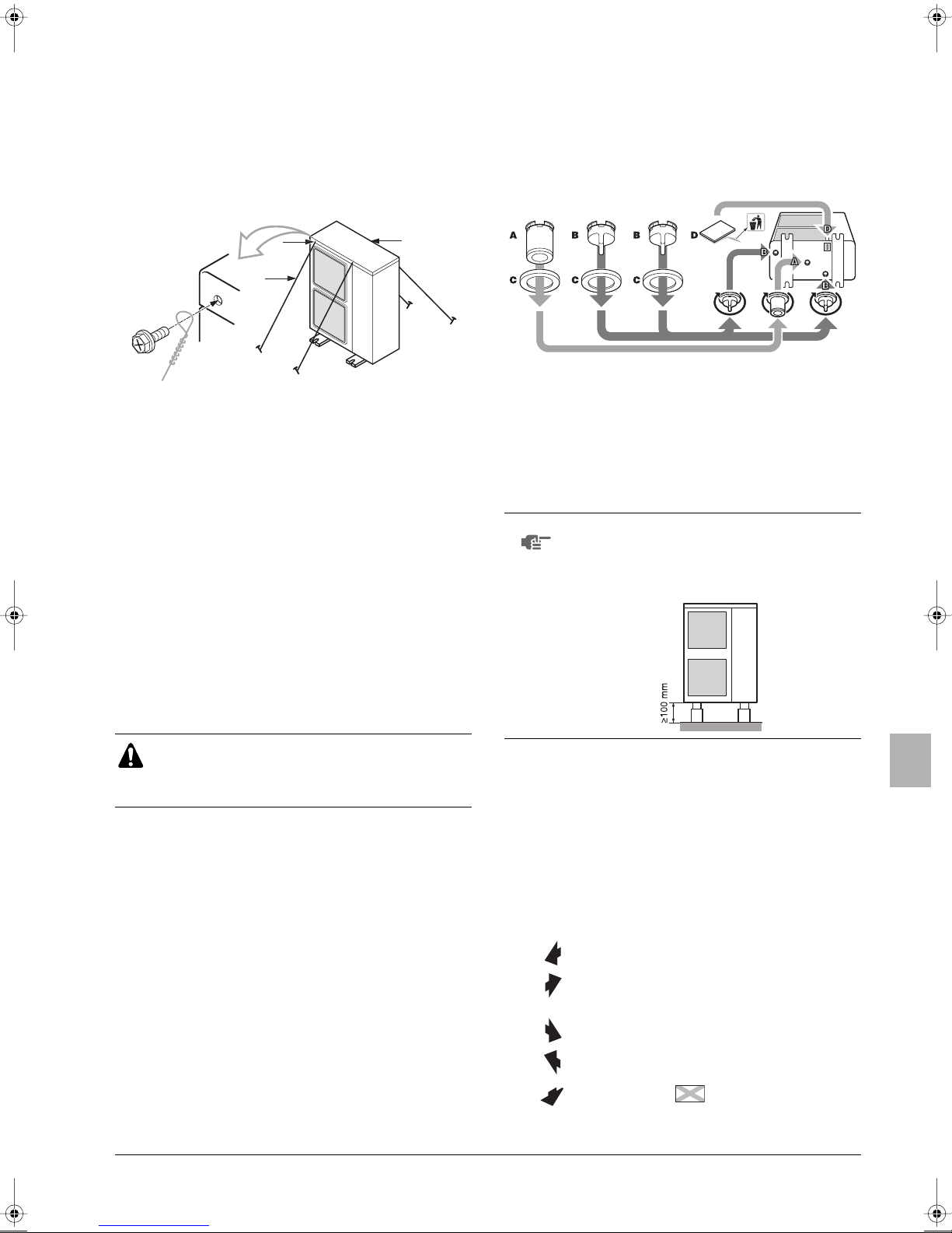
5.1. Installationsmethode zur Verhinderung des
Umstürzens der Anlage
Sollte es notwendig sein, ein Umstürzen der Anlage zu verhindern,
gehen Sie bei der Installation wie in der Abbildung vor.
■ Bereiten Sie alle 4 Haltekabel wie in der Zeichnung dargestellt
vor.
■ Lösen Sie die Schrauben der oberen Abdeckung an den vier mit
A und B bezeichneten Stellen.
■ Stecken Sie die Schrauben durch die Schlingen der Haltekabel,
und drehen Sie sie wieder fest.
5.3. Verfahren zur Installation der Kondensatleitung
Abhängig vom Installationsort, kann eine Installation des Kondensatstopfens für die Kondensatleitung erforderlich sein (Bausatz).
Verwenden Sie in kalten Gebieten keinen Kondensatschlauch
zusammen mit der Außeneinheit. Das Wasser kann ansonsten
gefrieren und die Heizleistung beeinträchtigen.
1 Siehe nachstehende Abbildung bezüglich der Installation des
Kondensatstopfens.
AA
B
C
A Position der beiden Befestigungslöcher auf der Vorderseite der
Einheit
B Position der beiden Befestigungslöcher auf der Rückseite der Einheit
C Kabel: bauseitig
5.2. Vorgehensweise zur Entfernung der
Transportstütze
Die gelbe Transportstütze, die über den Verdichterfüßen zum Schutz
des Geräts während des Transports angebracht ist, muss entfernt
werden. Gehen Sie wie in Abbildung 3 und wie nachfolgend
beschrieben vor.
A Verdichter
B Befestigungsmutter
C Tr ansportstütze
1 Lösen Sie jede Befestigungsmutter leicht (B).
2 Entfernen Sie jede Transportstütze (C), wie in Abbildung 3
dargestellt.
3 Ziehen Sie jede Befestigungsmutter (B) wieder an.
A Ablaufstutzen
B Kondensatkappe
C Kondensateinlass
D Isolierband
2 Schließen Sie einen bauseitigen Vinylschlauch (Innen-
durchmesser 25 mm) an den Kondensatstutzen (A) an.
Wenn der Schlauch zu lang ist und herunter hängt, befestigen
Sie ihn sorgfältig, um Knickstellen zu verhindern.
HINWEIS
Wenn die Kondensatöffnungen der Außeneinheit
durch eine Grundplatte oder Bodenfläche abgedeckt
sind, heben Sie die Einheit an, um für einen Freiraum
von mehr als 100 mm unter der Außeneinheit zu
sorgen.
VORSICHT
Wenn die Einheit mit der befestigten Transportstütze
betrieben wird, kann anormale Vibration oder Lärm
erzeugt werden.
U-4~6ML5DPQ + U-4~6ML5XPQ
Urban Multi Klimaanlage
4PW40731-1
6. PLATZBEDARF FÜR DIE INSTALLATION
■ Der Anschluss der Auslassleitungsrichtung in der Installation,
wie in Abbildung 4 dargestellt, erfolgt vorwärts oder nach unten.
Die Einheit der numerischen Werte beträgt mm.
■ Wenn Sie die Leitung rückwärts verlegen, muss ein sicherer
Abstand von ≥250 mm auf der rechten Seite der Einheit
sichergestellt werden.
(A) Bei nicht übereinander installierten Einheiten (Siehe
Abbildung 4)
1 Schließen Sie in diesen Fällen
den Boden des
Einbaurahmens, um zu
verhindern, dass die
ausgeblasene Luft umgeleitet
wird.
2 In diesen Fällen können nur 2
Einheiten installiert werden.
3 In diesen Fällen, gibt es keine
Einschränkung der Höhe L1.
Diese Situation ist nicht
zulässig.
Installationsanleitung
✓
Hindernis auf der
Ansaugseite
Hindernis auf der
Auslassseite
Hindernis auf der
linken Seite
Hindernis auf der
rechten Seite
Hindernis auf der
Oberseite
Hindernis
vorhanden
5

(B) Bei der Installation von mehreren Einheiten übereinander
000
1000
00
000
1. Wenn sich vor der Luftauslassseite ein Hindernis befindet.
A
100
≥1
2. Wenn sich vor der Lufteinlassseite ein Hindernis befindet.
A
100
≥300
HINWEIS
■ Installieren Sie auf keinen Fall mehr als eine
Einheit darüber.
■ Zur Verlegung des Ablaufrohrs des oberen
Außengeräts muss ein Abstand von etwa
100 mm eingehalten werden.
■ Dichten Sie Abschnitt A ab, so dass die aus
dem Auslass strömende Luft nicht umgeleitet
wird.
(C) Bei mehreren in Reihen installierten Einheiten (z.B. auf dem
Dach).
1. Bei Installation einer Einheit pro Reihe.
≥100
≥2
≥2
≥
2. Bei Installation mehrerer Einheiten (2 Einheiten oder mehr) pro
Reihe mit Seitenverbindung.
L
A
≥3000
H
≥600
≥1500
Die folgende Tabelle zeigt die Abmessungen H, A und L.
L A
L≤H
H<L Installation nicht möglich
0<L≤1/2H 250
1/2H<L≤H 300
7. DURCHMESSER UND MAXIMAL ZULÄSSIGE
ÄNGE DER KÄLTEMITTELLEITUNG
L
Sämtliche bauseitigen Rohrleitungen müssen von einem
qualifizierten Kältemitteltechniker installiert werden und
den jeweiligen örtlichen und staatlichen Vorschriften
entsprechen.
Hinweise zur Installation von Rohrleitungen:
■ Öffnen Sie auf jeden Fall das Absperrventil, nachdem
Sie die Rohrleitungen installiert und entlüftet haben.
(Ist das Absperrventil geschlossen, kann der
Verdichter irreparabel beschädigt werden.)
■ Es ist verboten, Kältemittelgas in die Atmosphäre
bzw. Umgebungsluft abzugeben. Fangen Sie das
Kältemittelgas gemäß dem Gesetz zur Sammlung
und Zerstörung von Freon auf.
■ Verwenden Sie beim Hartlöten der Kältemittelleitungen auf keinen Fall Flussmittel.
Verwenden Sie stattdessen aus Phosphor und Kupfer
bestehendes Lötzusatzmetall (BCuP), für das kein
Flussmittel erforderlich ist.
(Enthält das Kältemittel Chlor, können die Rohrleitungen korrodieren. Fluor kann das im Kältemittel
enthaltene Flussmittel auflösen, was ebenfalls einen
nachteiligen Effekt auf die Kältemittelleitungen hätte.)
7.1. Auswahl der Rohrleitungsmaterialien
■ Die Menge fremder Materialien in Rohrleitungen (einschließlich
Öle aus der Herstellung) darf 30 mg/10 m nicht überschreiten.
■ Baumaterial: Phosphorsäure-deoxidierte Kupferrohre für
Kältemittel.
■ Härtegrad: Verwenden Sie Rohrleitungssysteme mit Härtegrad
unter Berücksichtigung des Rohrdurchmessers, wie in
untenstehender Tabelle aufgelistet.
■ Die Rohrwandstärke der Kältemittelleitungen muss den geltenden lokalen und nationalen Vorschriften entsprechen. Die
Mindestrohrwandstärke für Rohrleitung R410A muss der
untenstehenden Tabelle entsprechen.
Rohr-
durchmesser
6,4 / 9,5 / 12,7 O 0,80
15,9 O 1
19,1 1/2H 1
O = geglüht
1/2H = halb hart
■ Achten Sie darauf, dass Sie die entsprechenden
Leitungsabzweigungen verwenden, die ausgewählt wurden.
■ Sollten keine Rohreitungen in der erforderlichen Größe
(Maßeinheit Zoll) zur Verfügung stehen, können auch Leitungen
mit anderen Durchmessern (Maßeinheit Millimeter) verwendet
werden. Dabei muss Folgendes berücksichtigt werden:
■ Wählen Sie eine Rohrleitungsgröße aus, die der benötigten
Leitungsgröße am nächsten kommt.
■ Verwenden Sie die entsprechenden Adapter zum Aufsetzen
von (bauseitigen) Millimeterleitungen auf Zollleitungen.
Härtegrad des
Rohrleitungsmaterials
Mindeststärke t(mm)
Installationsanleitung
6
U-4~6ML5DPQ + U-4~6ML5XPQ
Urban Multi Klimaanlage
4PW40731-1
 Loading...