

Panasonic U-4..6ML5XPQ, U-4..6ML5DPQ Service Manual

Service Manual
U-4..6ML5XPQ/DPQ
Urban Multi - Mini UM - Heat Pump


Table of Contents i
Mini UM ML4 - R-410A
Heat Pump
50Hz
1. Introduction ............................................................................................v
1.1 Safety Cautions........................................................................................v
1.2 PREFACE ...............................................................................................ix
Part 1 General Information ........................................................... 1
1. Model Names of Indoor/Outdoor Units....................................................2
2. External Appearance...............................................................................3
2.1 Indoor Units..............................................................................................3
3. Capacity Range.......................................................................................4
Part 2 Specifications .................................................................... 5
1. Specifications..........................................................................................6
1.1 Outdoor Units...........................................................................................6
1.2 Indoor Units............................................................................................10
Part 3 List of Electrical and Functional Parts............................ 29
1. List of Electrical and Functional Parts...................................................30
1.1 Outdoor Unit...........................................................................................30
1.2 Indoor Unit..............................................................................................32
Part 4 Refrigerant Circuit ........................................................... 39
1. Refrigerant Circuit.................................................................................40
1.1 Outdoor Unit...........................................................................................40
2. Functional Parts Layout ........................................................................44
2.1 U-4, 5, 6ML5XPQ ..................................................................................44
2.2 U-4, 5, 6ML5DPQ ..................................................................................45
Part 5 Function............................................................................47
1. Operation Mode ....................................................................................48
2. Basic Control.........................................................................................49
2.1 Normal Operation...................................................................................49
2.2 Compressor PI Control................... ........................................................50
2.3 Electronic Expansion Valve PI Control...................................................51
2.4 Cooling Operation Fan Control...............................................................52
3. Special Control......................................................................................53
3.1 Startup Control.......................................................................................53
3.2 Oil Return Operation ..............................................................................54
3.3 Defrosting Operation..............................................................................56
3.4 Pump-down Residual Operation ............................................................57
Panasonic

ii Table of Contents
3.5 Restart Standby......................................................................................58
3.6 Stopping Operation ................................................................................59
4. Protection Control .................................................................................60
4.1 High Pressure Protection Control ...........................................................60
4.2 Low Pressure Protection Control............................................................61
4.3 Discharge Pipe Protection Control.........................................................62
4.4 Inverter Protection Control .....................................................................63
5. Other Control.........................................................................................64
5.1 Demand Operation.................................................................................64
5.2 Heating Operation Prohibition................................................................64
6. Outline of Control (Indoor Unit).............................................................65
6.1 Drain Pump Control ................................................................................65
6.2 Louver Control for Preventing Ceiling Dirt..............................................67
6.3 Thermostat Sensor in Remote Controller...............................................68
6.4 Freeze Prevention..................................................................................70
6.5 View of Operations of Swing Flaps ........................................................71
6.6 Electronic Expansion Valve Control.......................................................72
6.7 Hot Start Control (In Heating Operation Only)........................................72
Part 6 Test Operation .................................................................73
1. Test Operation ......................................................................................74
1.1 Procedure and Outline ...........................................................................74
1.2 Operation when Power is Turned On.....................................................85
2. Outdoor Unit PC Board Layout .............................................................86
3. Field Setting..........................................................................................87
3.1 Field Setting from Remote Controller.....................................................87
3.2 Field Setting from Outdoor Unit............................................................104
Part 7 Troubleshooting .............................................................123
1. Symptom-based Troubleshooting.......................................................125
2. Troubleshooting by Remote Controller ...............................................128
2.1 The INSPECTION / TEST Button.........................................................128
2.2 Self-diagnosis by Wired Remote Controller .........................................129
2.3 Self-diagnosis by Wireless Remote Controller.....................................130
2.4 Operation of the Remote Controller’s Inspection /
Test Operation Button..........................................................................132
2.5 Remote Controller Service Mode.........................................................133
2.6 Remote Controller Self-Diagnosis Function.........................................135
3. Troubleshooting by Indication on the Remote Controller....................142
3.1 “A0” Indoor Unit: Error of External Protection Device............................142
3.2 “A1” Indoor Unit: PC Board Defect........................................................143
3.3 “A3” Indoor Unit: Malfunction of Drain Level Control System (S1L)......144
3.4 “A6” Indoor Unit: Fan Motor (M1F) Lock, Overload...............................146
3.5 “A7” Indoor Unit: Malfunction of Swing Flap Motor (M1S).....................147
3.6 Abnormal Power Supply Voltage..........................................................149
3.7 “A9” Indoor Unit: Malfunction of Moving Part of
Electronic Expansion Valve (Y1E)........................................................150
3.8 “AF” Indoor Unit: Drain Level above Limit .............................................152
3.9 “AJ” Indoor Unit: Malfunction of Capacity Determination Device..........153
Urban Multi ML5 · Mini UM · Heat Pump

Table of Contents iii
3.10 “C1” Indoor Unit: Failure of Transmission
(Between Indoor unit PC Board and Fan PC Board)............................154
3.11 “C4” Indoor Unit: Malfunction of Thermistor (R2T)
for Heat Exchanger ..............................................................................156
3.12 “C5” Indoor Unit: Malfunction of Thermistor (R3T) for Gas Pipes .........157
3.13 “C6” Indoor Unit: Failure of Combination
(Between Indoor unit PC Board and Fan PC Board)............................158
3.14 “C9” Indoor Unit: Malfunction of Thermistor (R1T) for Suction Air.........159
3.15 “CA” Indoor Unit: Malfunction of Thermistor for Discharge Air...............160
3.16 “CC” Indoor Unit: Malfunction of Humidity Sensor System....................161
3.17 “CJ” Indoor Unit: Malfunction of Thermostat Sensor in
Remote Controller................................................................................162
3.18 “E1” Outdoor Unit: PC Board Defect.....................................................163
3.19 “E3” Outdoor Unit: Actuation of High Pressure Switch..........................164
3.20 “E4” Outdoor Unit: Actuation of Low Pressure Sensor..........................166
3.21 “E5” Inverter Compressor Motor Lock...................................................168
3.22 “E7” Malfunction of Outdoor Unit Fan Motor .........................................169
3.23 “E9” Outdoor Unit: Malfunction of Moving Part of
Electronic Expansion Valve (Y1E, Y3E)...............................................170
3.24 “F3” Outdoor Unit: Abnormal Discharge Pipe Temperature..................172
3.25 “F6” Outdoor Unit: Refrigerant Overcharged.........................................173
3.26 “H9” Outdoor Unit: Malfunction of Thermistor (R1T) for Outdoor Air.....174
3.27 “J3” Outdoor Unit: Malfunction of Discharge Pipe Thermistor (R2T)....175
3.28 “J5” Outdoor Unit: Malfunction of Thermistor (R3T, R5T) for
Suction Pipe 1, 2..................................................................................176
3.29 “J6” Outdoor Unit: Malfunction of Thermistor (R6T) .............................177
3.30 “J7” Outdoor Unit: Malfunction of Thermistor (R7T) for
Outdoor Unit Liquid Pipe......................................................................1 78
3.31 “J9” Outdoor Unit: Malfunction of Thermistor (R4T) .............................179
3.32 “JA” Outdoor Unit: Malfunction of High Pressure Sensor......................180
3.33 “JC” Outdoor Unit: Malfunction of Low Pressure Sensor ......................181
3.34 “L1” Outdoor Unit: Malfunction of PC Board.........................................182
3.35 “L4” Outdoor Unit: Malfunction of Inverter Radiating Fin
Temperature Rise.................................................................................183
3.36 “L5” Outdoor Unit: Inverter Compressor Abnormal...............................184
3.37 “L8” Outdoor Unit: Inverter Current Abnormal.......................................185
3.38 “L9” Outdoor Unit: Inverter Start up Error .............................................186
3.39 “LC” Outdoor Unit: Malfunction of Transmission between
Inverter and Control PC Board.............................................................187
3.40 “P1” Outdoor Unit: High Voltage of Capacitor in
Main Inverter Circuit.............................................................................188
3.41 “U0” Low Pressure Drop Due to Refrigerant Shortage or
Electronic Expansion Valve Failure......................................................189
3.42 “U2” Power Supply Insufficient or Instantaneous Failure ......................191
3.43 “U3” Check Operation not Executed......................................................193
3.44 “U4” Malfunction of Transmission between Indoor Units and
Outdoor Units.......................................................................................194
3.45 “U5” Malfunction of Transmission between Remote Controller and
Indoor Unit............................................................................................196
3.46 “U8” Malfunction of Transmission between Main and
Sub Remote Controllers.......................................................................197
3.47 “U9” Malfunction of Transmission between Indoor and
Outdoor Units in the Same System......................................................198
Panasonic

iv Table of Contents
3.48 “UA” Excessive Number of Indoor Units................................................200
3.49 “UC” Address Duplication of Central Remote Controller........................201
3.50 “UE” Malfunction of Transmission between
Central Remote Controller and Indoor Unit..........................................202
3.51 “UF” System is not Set yet.....................................................................204
3.52 “UH” Malfunction of System, Refrigerant System Address Undefined...205
4. Troubleshooting by Indication on
the Centralized Remote Controller......................................................206
4.1 “UE” Malfunction of Transmission between
Centralized Remote Controller and Indoor Unit ...................................206
4.2 “M1” PC Board Defect...........................................................................207
4.3 “M8” Malfunction of Transmission between
Optional Controllers for Centralized Control.........................................208
4.4 “MA” Improper Combination of Optional Controllers for
Centralized Control...............................................................................209
4.5 “MC” Address Duplication, Improper Setting .........................................211
5. Troubleshooting by Indication on the Unified ON/OFF Controller.......212
5.1 Operation Lamp Blinks.........................................................................212
5.2 Display “Under Host Computer Integrate Control” Blinks
(Repeats Single Blink)..........................................................................214
5.3 Display “Under Host Computer Integrate Control” Blinks
(Repeats Double Blink) ........................................................................217
Part 8 Appendix.........................................................................221
1. Piping Diagrams..................................................................................222
1.1 Outdoor Unit.........................................................................................222
1.2 Indoor Unit............................................................................................224
2. Wiring Diagrams..................................................................................227
2.1 Outdoor Unit.........................................................................................227
2.2 Field Wiring ..........................................................................................229
2.3 Indoor Unit............................................................................................231
3. Option List...........................................................................................246
3.1 Option List of Controllers......................................................................246
3.2 Option List of Outdoor Unit...................................................................248
4. Example of Connection.......................................................................249
5. Thermistor Resistance / Temperature Characteristics........................251
6. Pressure Sensor .................................................................................253
7. Method of Replacing the Inverter’s Power Transistors Modules.........254
Part 9 Precautions for New Refrigerant (R-410A)....................257
1. Precautions for New Refrigerant (R-410A) .........................................258
1.1 Outline..................................................................................................258
1.2 Refrigerant Cylinders............................................................................260
1.3 Service Tools........................................................................................261
Index .............................................................................................i
Drawings & Flow Charts ...............................................................iii
Urban Multi ML5 · Mini UM · Heat Pump
Introduction
v
1. Introduction
1.1 Safety Cautions
Cautions and
Warnings
Be sure to read the following safety cautions before conducting repair work.
The caution items are classified into “ Warning” and “ Caution”. The “ Warning”
items are especially important since they can lead to death or serious injury if they are not
followed closely. The “ Caution” items can also lead to serious accidents under some
conditions if they are not followed. Therefore, be sure to observe all the safety caution item s
described below.
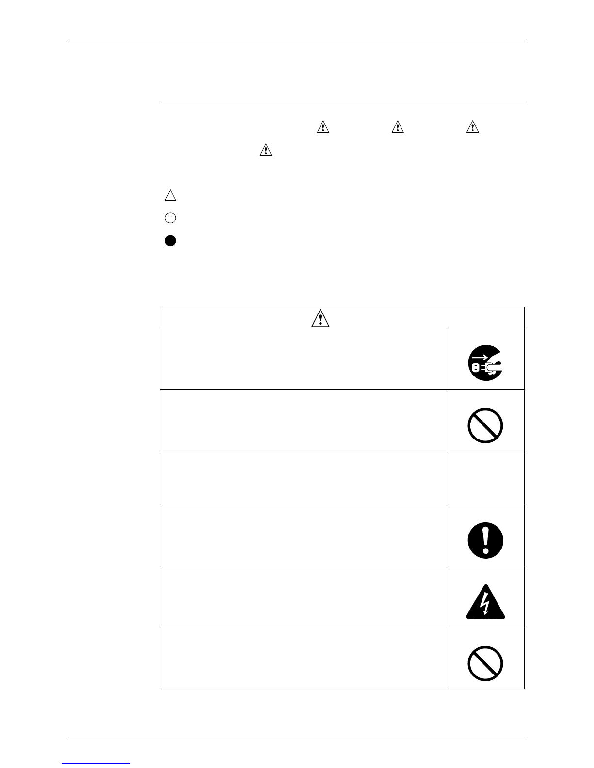
About the pictograms
This symbol indicates an item for which caution must be exercised.
The pictogram shows the item to which attention must be paid.
This symbol indicates a prohibited action.
The prohibited item or action is shown inside or near the symbol.
This symbol indicates an action that must be taken, or an instruction.
The instruction is shown inside or near the symbol.
After the repair work is complete, be sure to conduct a test operation to ensure that the
equipment operates normally, and explain the cautions for operating the product to the
customer
1.1.1 Caution in Repair
Warning
Be sure to disconnect the power cable plug from the plug socket before
disassembling the equipment for a repair.
Working on the equipment that is connected to a power supply can cause an
electrical shook.
If it is necessary to supply power to the equipment to conduct the repair or
inspecting the circuits, do not touch any electrically charged sections of the
equipment.
If the refrigerant gas discharges during the repair work, do not touch the
discharging refrigerant gas.
The refrigerant gas can cause frostbite.
When disconnecting the suction or discharge pipe of the compressor at the
welded section, release the refrigerant gas completely at a well-ventilated
place first.
If there is a gas remaining inside the compressor, the refrig e r an t g as or
refrigerating machine oil discharges when the pipe is disconnected, and it can
cause injury.
If the refrigerant gas leaks during the repair work, ventilate the area. The
refrigerant gas can generate toxic gases when it contacts flames.
The step-up capacitor supplies high-voltage electricity to the electrical
components of the outdoor unit.
Be sure to discharge the capacitor completely before conducting repair work.
A charged capacitor can cause an electrical shock.
Do not start or stop the air conditioner operation by plugging or unplugging the
power cable plug.
Plugging or unplugging the power cable plug to operate the equipment can
cause an electrical shock or fire.
Panasonic
Introduction
vi
1.1.2 Cautions Regarding Products after Repair
Caution
Do not repair the electrical components with wet hands.
Working on the equipment with wet hands can cause an electrical shock.
Do not clean the air conditioner by splashing water.
Washing the unit with water can cause an electrical shock.
Be sure to provide the grounding when repairing the equipment in a humid or
wet place, to avoid electrical shocks.
Be sure to turn off the power switch and unplug the power cable when cleaning
the equipment.
The internal fan rotates at a high speed, and cause injury.
Do not tilt the unit when removing it.
The water inside the unit can spill and wet the furniture and floor.
Be sure to check that the refrigerating cycle section has cooled down
sufficiently before conducting repair work.
Working on the unit when the refrigerating cycle section is hot can cause burns.
Use the welder in a well-ventilated place.
Using the welder in an enclosed room can cause oxygen deficiency.
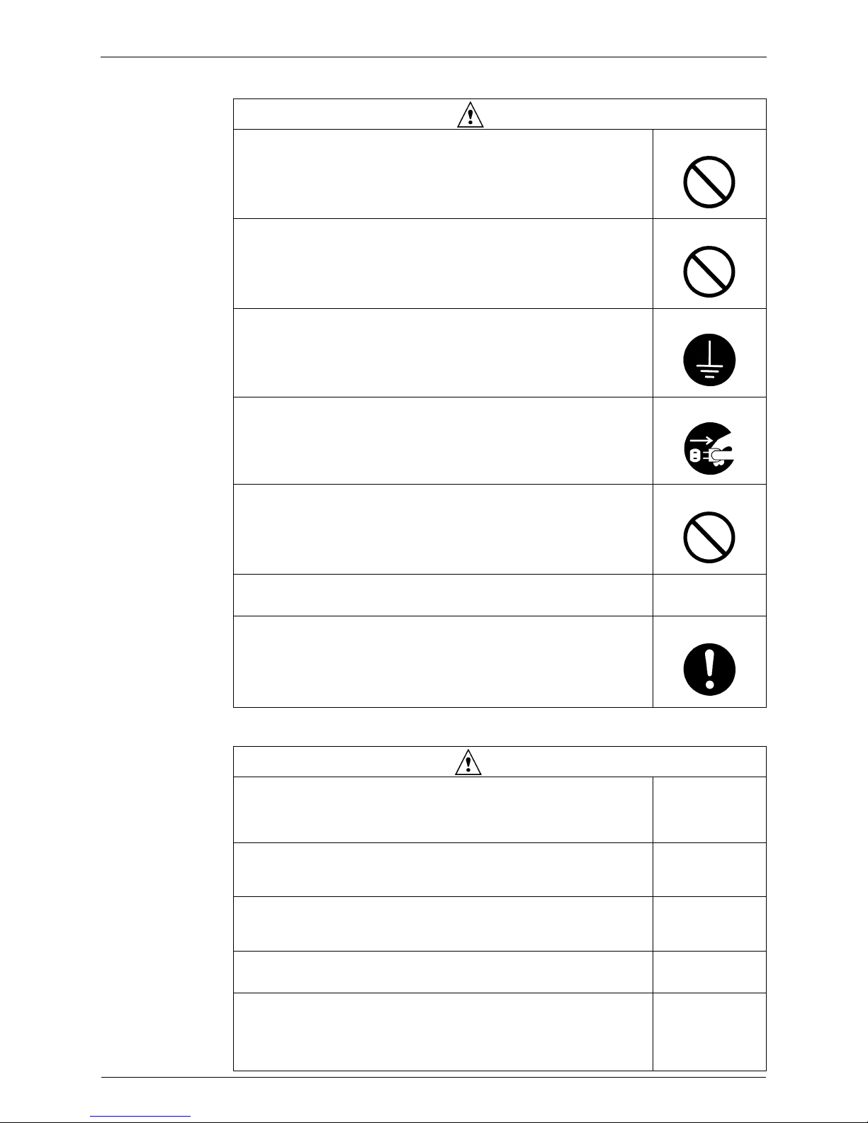
Warning
Be sure to use parts listed in the service parts list of the applicable model and
appropriate tools to conduct repair work. Never attempt to modify the
equipment.
The use of inappropriate parts or tools can cause an electrical shock,
excessive heat generation or fire.
When relocating the equipment, make sure that the new installation site has
sufficient strength to withstand the weight of the equipment.
If the installation site does not have sufficient strength and if the installation
work is not conducted securely, the equipment can fall and cause injury.
Be sure to install the product correctly by using the provided standard
installation frame.
Incorrect use of the installation frame and improper install ation can cause the
equipment to fall, resulting in injury.
For integral units
only
Be sure to install the product securely in the installation frame mounted on a
window frame.
If the unit is not securely mounted, it can fall and cause injury.
For integral units
only
Be sure to use an exclusive power circuit for the equipment, and follow the
technical standards related to the electrical equipment, the internal wiring
regulations and the instruction manual for installation when conducting
electrical work.
Insufficient power circuit capacity and improper electrical work can cause an
electrical shock or fire.
Urban Multi ML5 · Mini UM · Heat Pump
Introduction
vii
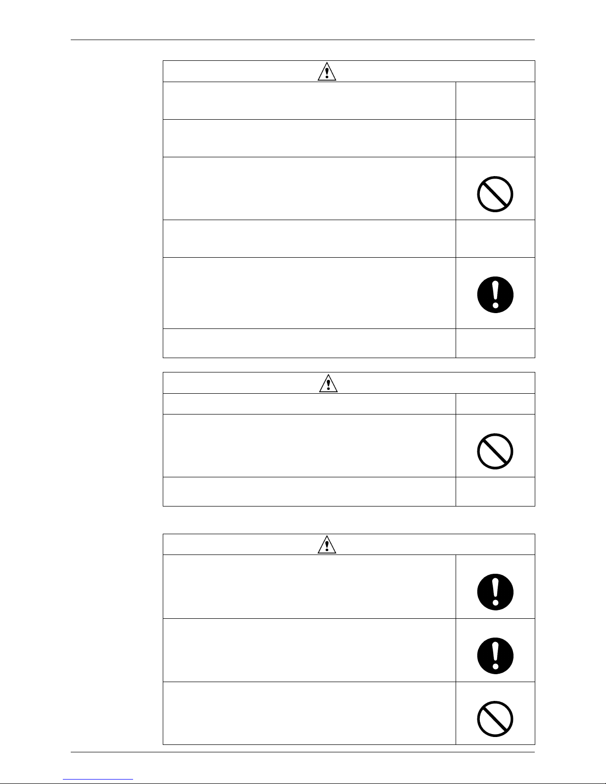
1.1.3 Inspection after Repair
Be sure to use the specified cable to connect between the indoor and outdoor
units. Make the connections securely and route the cable properly so that there
is no force pulling the cable at the connection terminals.
Improper connections can cause excessive heat generation or fire.
When connecting the cable between the indoor and outdoor units, make sure
that the terminal cover does not lift off or dismount because of the cable.
If the cover is not mounted properly, the terminal connection section can cause
an electrical shock, excessive heat generation or fire.
Do not damage or modify the power cable.
Damaged or modified power cable can cause an electrical shock or fire.
Placing heavy items on the power cable, and heating or pulling the power cable
can damage the cable.
Do not mix air or gas other than the specified refrigerant (R-410A) in the
refrigerant system.
If air enters the refrigerating system, an excessively high pressure results,
causing equipment damage and injury.
If the refrigerant gas leaks, be sure to locate the leak and repair it before
charging the refrigerant. After charging refrigerant, make sure that there is no
refrigerant leak.
If the leak cannot be located and the repair work mu st be stopped, be sure to
perform pump-down and close the service valve, to prevent the refrigerant gas
from leaking into the room. The refrigerant gas itself is harmless, but it can
generate toxic gases when it contacts flames, such as fan and other heaters,
stoves and ranges.
When replacing the coin battery in the remote controller, be sure to disposed
of the old battery to prevent children from swallowing it.
If a child swallows the coin battery, see a doctor immediately.
Warning
Caution
Installation of a leakage breaker is necessary in some cases depending on the
conditions of the installation site, to prevent electrical shocks.
Do not install the equipment in a place where there is a possibility of
combustible gas leaks.
If a combustible gas leaks and remains around the unit, it can cause a fire.
Be sure to install the packing and seal on the installation frame properly.
If the packing and seal are not installed properly, water can enter the room and
wet the furniture and floor.
For integral units
only
Warning
Check to make sure that the power cable plug is not dirty or loose, then insert
the plug into a power outlet all the way.
If the plug has dust or loose connection, it can cause an electrical shock or fire.
If the power cable and lead wires have scratches or deteriorated, be sure to
replace them.
Damaged cable and wires can cause an electrical shock, excessive heat
generation or fire.
Do not use a joined power cable or extension cable, or share the same power
outlet with other electrical appliances, since it can cause an electrical shock,
excessive heat generation or fire.
Panasonic
Introduction
viii
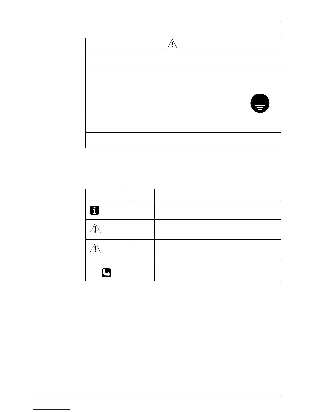
1.1.4 Using Icons
Icons are used to attract the attention of the reader to specific information. The m eaning of each
icon is described in the table below:
1.1.5 Using Icons List
Caution
Check to see if the parts and wires are mounted and connected properly, and
if the connections at the soldered or crimped terminals are secure.
Improper installation and connections can cause excessive heat generation,
fire or an electrical shock.
If the installation platform or frame has corroded, replace it.
Corroded installation platform or frame can cause the unit to fall, resulting in
injury.
Check the grounding, and repair it if the equipment is not properly grounded.
Improper grounding can cause an electrical shock.
Be sure to measure the insulation resistance after the repair, and make sure
that the resistance is 1 Mohm or higher.
Faulty insulation can cause an electrical shock.
Be sure to check the drainage of the indoor unit after the repair.
Faulty drainage can cause the water to enter the room and wet the furniture
and floor.
Icon Type of
Information
Description
Note:
Note A “note” provides information that is not indispensable, but may
nevertheless be valuable to the reader, such as tips and tricks.
Caution
Caution A “caution” is used when there is danger that the reader, through
incorrect manipulation, may damage equipment, loose data, get
an unexpected result or has to restart (part of) a procedure.
Warning
Warning A “warning” is used when there is danger of personal injury.
Reference A “reference” guides the reader to other places in this binder or
in this manual, where he/she will find additional information on a
specific topic.
Urban Multi ML5 · Mini UM · Heat Pump

Introduction
ix
1.2 PREFACE
Thank you for your continued patronage of Panasonic products.
This is the new service manual for Panasonic's Year 2008 UM ML5 series Heat Pump System.
Panasonic offers a wide range of models to respond to building and office air conditioning needs.
We are confident that customers will be able to find th e models that best suit their needs .
This service manual contains information regarding the servicing of UM ML5 series R-410A
Heat Pump System.
July, 2008
After Sales Service Division
Panasonic

Introduction
x
Urban Multi ML5 · Mini UM · Heat Pump

General Information 1
Part 1
General Information
1. Model Names of Indoor/Outdoor Units....................................................2
2. External Appearance...............................................................................3
2.1 Indoor Units..............................................................................................3
3. Capacity Range.......................................................................................4
Panasonic
Model Names of Indoor/Outdoor Units
2 General Information
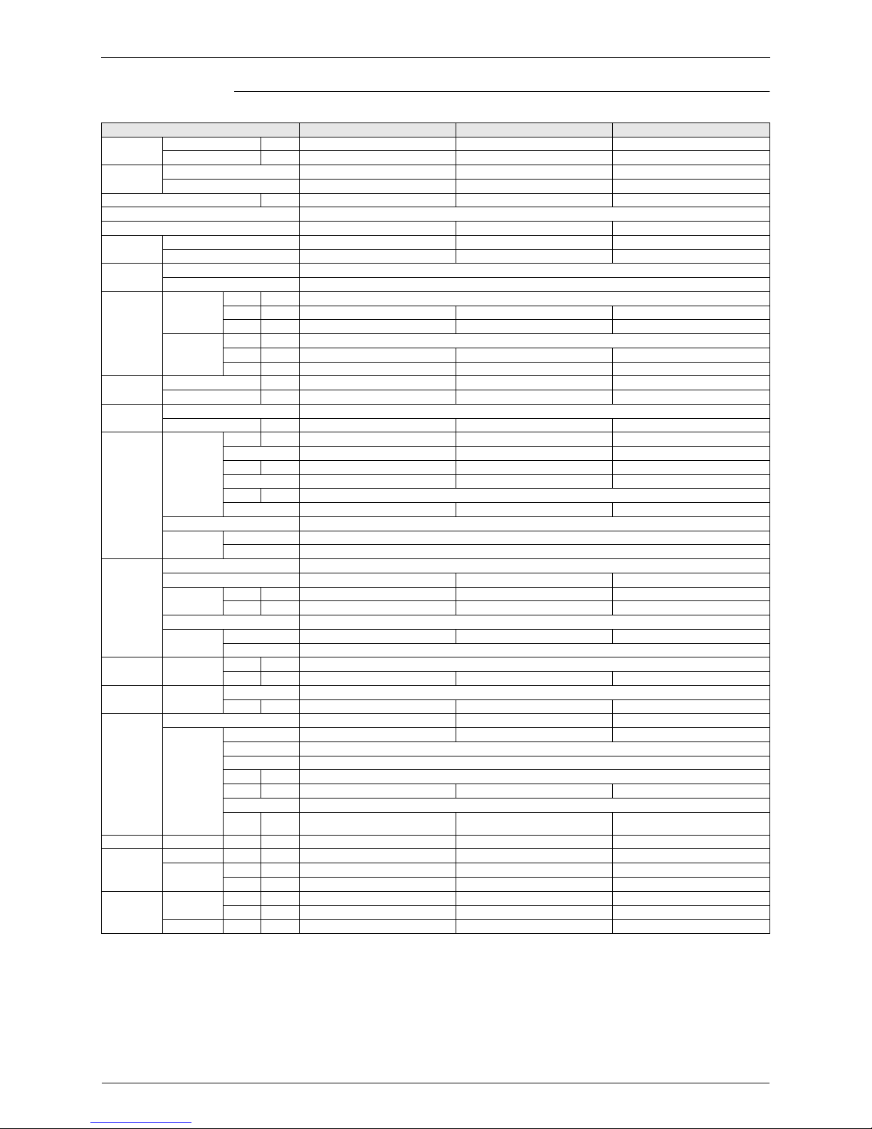
1. Model Names of Indoor/Outdoor Units
*Indoor Units
Note: VE:1f, 220~240V, 50Hz, 1f, 220V, 60Hz
V1:1f, 220~240V, 50Hz
V3:1f, 230V, 50Hz
Outdoor Units
Type Model Name
Power Supply
Ceiling Mounted
Cassette Type
(Double Flow)
LM3 20 25 32 40 50 63 80 —
125
V3
Ceiling Mounted
Cassette Type
(Round Flow)
UM4 20 25 32 40 50 63 80 100 125 VE
600×600 Ceiling
Mounted Cassette
Type (Mult Flow)
YM3 20 25 32 40 50————V1
Ceiling Mounted
Cassette Corner
Type
DM3 —
25 32 40 — 63 ——— VE
Ceiling Mounted
Built-In Type
FM3 20 25 32 40 50 63 80 100 125
Ceiling Mounted
Duct Type
EM3 ——— 40 50 63 80
100 125
VE
Ceiling Suspended
Type
TM3 —— 32 —— 63 — 100 —
Wall Mounted
Type
KM3 20 25 32 40 50 63 ———
Floor Standing
Type
PM3 20 25 32 40 50 63 ———
Concealed Floor
Standing Type
RM3 20 25 32 40 50 63 ———
Series Model Name
Power Supply
Inverter Heat Pump U-ML5 4 5 6 Y1, V1
Y1 :3φ, 380~415V, 50Hz
V1 :1φ, 220~240V, 50Hz
Concealed Ceiling
Unit (Small)
NM3 20 25 —— —————
V3
Urban Multi ML5 · Mini UM · Heat Pump
External Appearance
General Information 3
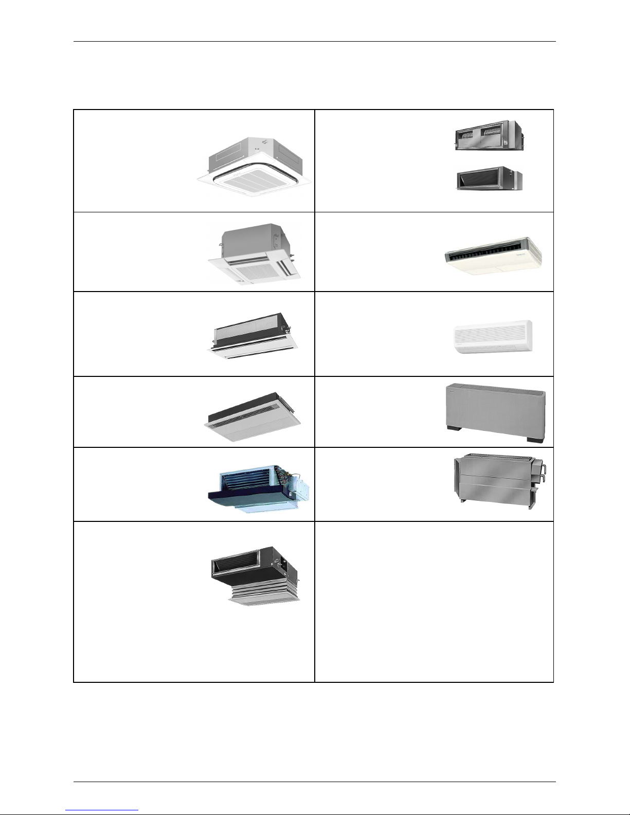
2. External Appearance
2.1 Indoor Units
Roundflow Ceiling Mounted Cassette
S-20UM4JPQ
S-25UM4JPQ
S-32UM4JPQ
S-40UM4JPQ
S-50UM4JPQ
S-63UM4JPQ
S-80UM4JPQ
S-100UM4JPQ
S-125UM4JPQ
Concealed Ceiling Unit
(Large)
S-40EM3HPS
S-50EM3HPS
S-63EM3HPS
S-80EM3HPS
S-100EM3HPS
S-125EM3HPS
S-200EM3HPS
S-250EM3HPS
S-40..125EM3HPS
S-200..250EM3HPS
600×600 4-Way Blow
Ceiling Mounted Cassette
S-20YM3HPQ
S-25YM3HPQ
S-32YM3HPQ
S-40YM3HPQ
S-50YM3HPQ
Ceiling Suspended Unit
S-32TM3JPR
S-63TM3JPR
S-100TM3JPR
2-Way Blow Ceiling Mounted Cassette
S-20LM3HPQ
S-25LM3HPQ
S-32LM3HPQ
S-40LM3HPQ
S-50LM3HPQ
S-63LM3HPQ
S-80LM3HPQ
S-125LM3HPQ
Wall Mounted Unit
S-20KM3HPR
S-25KM3HPR
S-32KM3HPR
S-40KM3HPR
S-50KM3HPR
S-63KM3HPR
Ceiling Mounted Corner Cassette
S-25DM3HPS
S-32DM3HPS
S-40DM3HPS
S-63DM3HPS
Floor Standing Unit
S-20PM3HPS
S-25PM3HPS
S-32PM3HPS
S-40PM3HPS
S-50PM3HPS
S-63PM3HPS
Concealed Floor Standing Unit
S-20RM3HPS
S-25RM3HPS
S-32RM3HPS
S-40RM3HPS
S-50RM3HPS
S-63RM3HPS
Concealed Ceiling Unit (Small)
S-20NM3HPQ
S-25NM3HPQ
Concealed Ceiling Unit
S-20FM3HPQ
S-25FM3HPQ
S-32FM3HPQ
S-40FM3HPQ
S-50FM3HPQ
S-63FM3HPQ
S-80FM3HPQ
S-100FM3HPQ
S-125FM3HPQ
Panasonic
Capacity Range
4 General Information
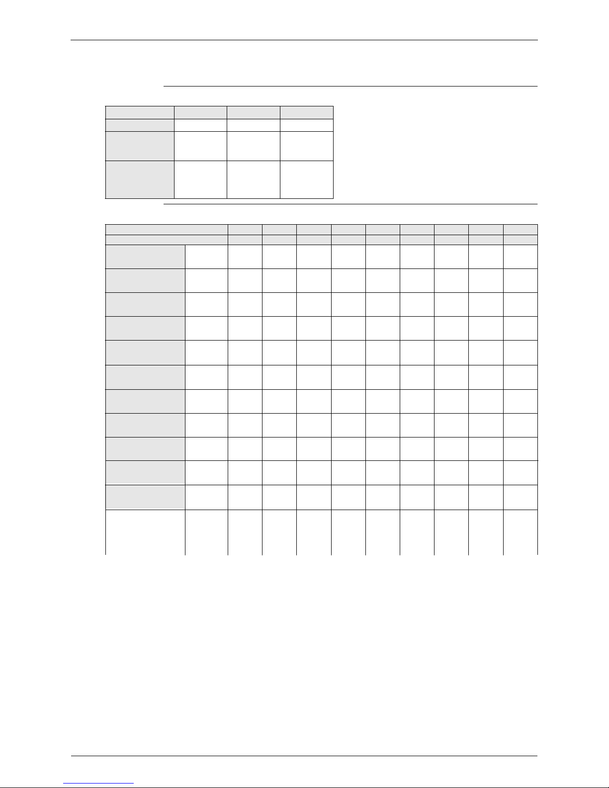
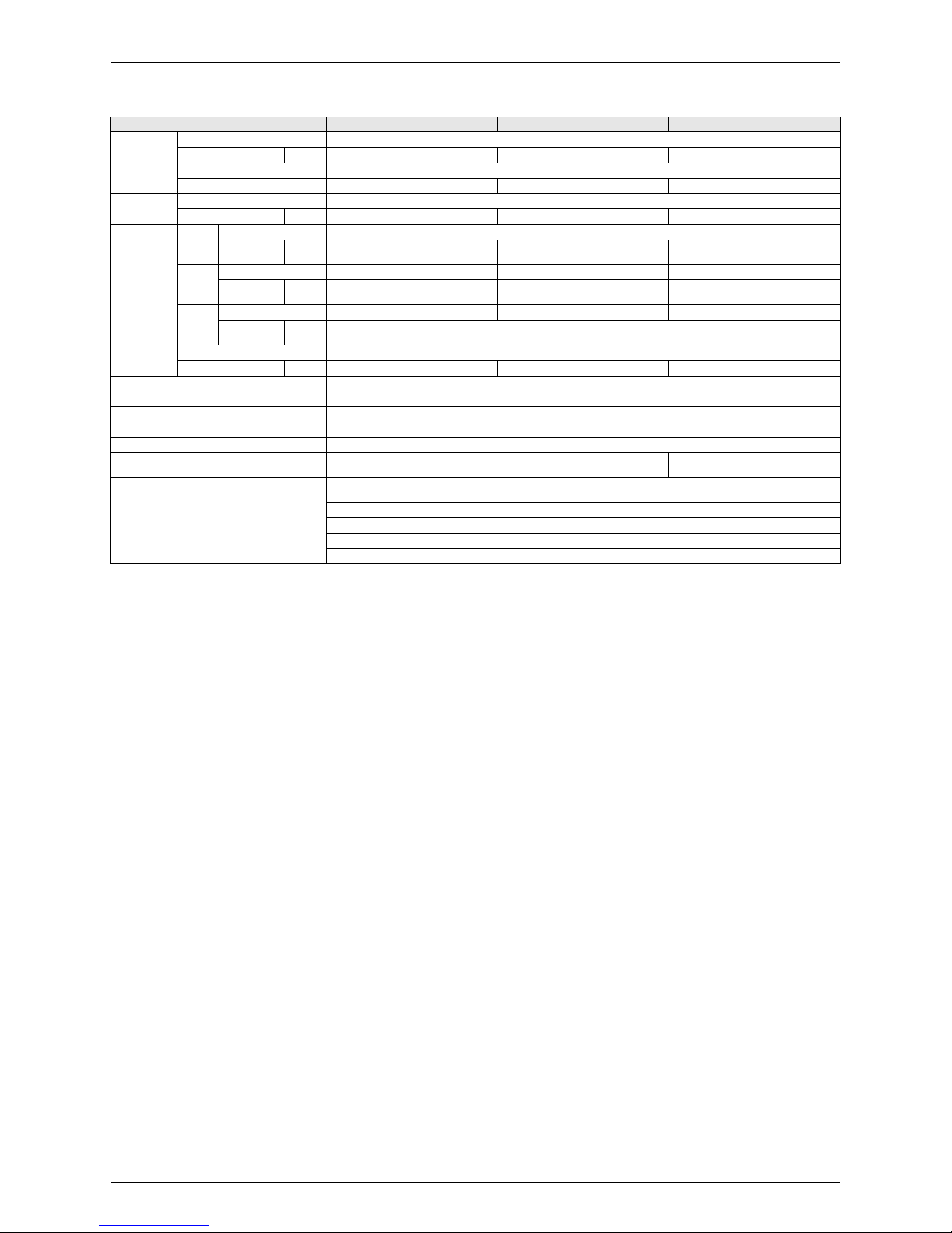
3. Capacity Range
Outdoor Units
Indoor Units
Capacity Range 4HP 5HP 6HP
U-ML5 4 5 6
No of Indoor
Units to be
Connected
689
Total Capacity
Index of Indoor
Units to be
Connected
50~130 62.5~162.5 70~182
Capacity Range 0.8HP 1HP
1.25HP
1.6HP 2HP 2.5HP 3.2HP 4HP 5HP
Capacity Index 20 25 31.25 40 50 62.5 80 100 125
Ceiling Mounted
Cassette Type
(Double Flow)
LM3 20 25 32 40 50 63 80 — 125
Ceiling Mounted
Cassette Type
(Round Flow)
UM4 20 25 32 40 50 63 80 100 125
600×600 Ceiling
Mounted Cassette
Type (Multi Flow)
YM3 20 25 32 40 50 ————
Ceiling Mounted
Cassette Corner Type
DM3 — 25 32 40 — 63 ———
Ceiling Mounted
Built-In Type
FM3 20 25 32 40 50 63 80 100 125
Ceiling Mounted
Duct Type
EM3 ———40 50 63 80 100 125
Ceiling Suspended
Type
TM3 —— 32 —— 6 —3 100 —
Wall Mounted Type
KM3 20 25 32 40 50 63 ———
Floor Standing Type
PM3 20 25 32 40 50 63 ———
Concealed Floor
Standing Type
RM3
20 25 32 40 50 63 ———
Concealed Cealing
Mounted (Small)
NM3 20 25 32 40 50 63 80 100 125
Urban Multi ML5 · Mini UM · Heat Pump

Specifications 5
Part 2
Specifications
1. Specifications..........................................................................................6
1.1 Outdoor Units...........................................................................................6
1.2 Indoor Units............................................................................................10
Panasonic
Specifications
6 Specifications
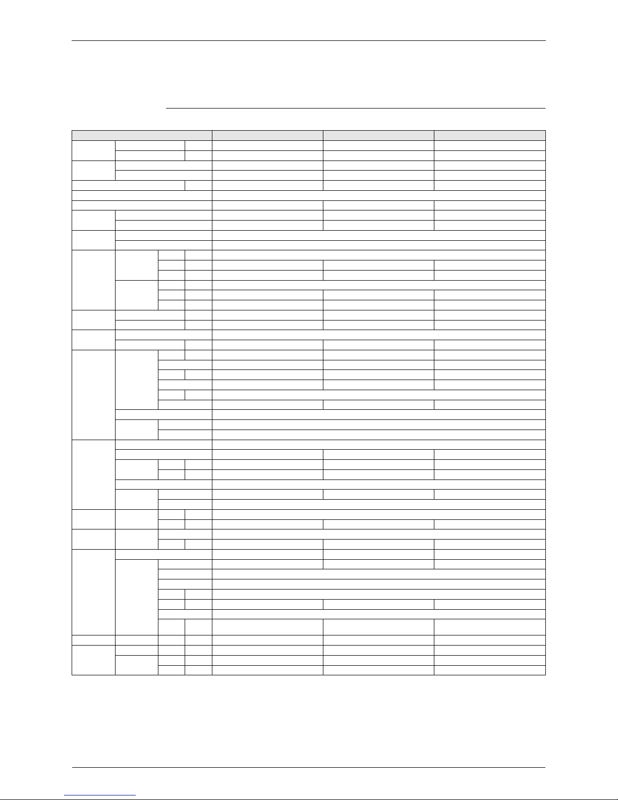
1. Specifications
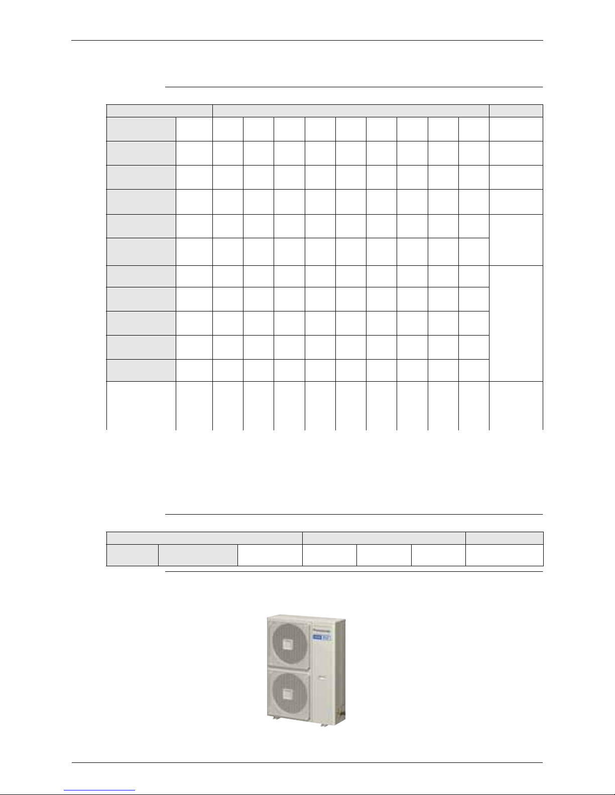
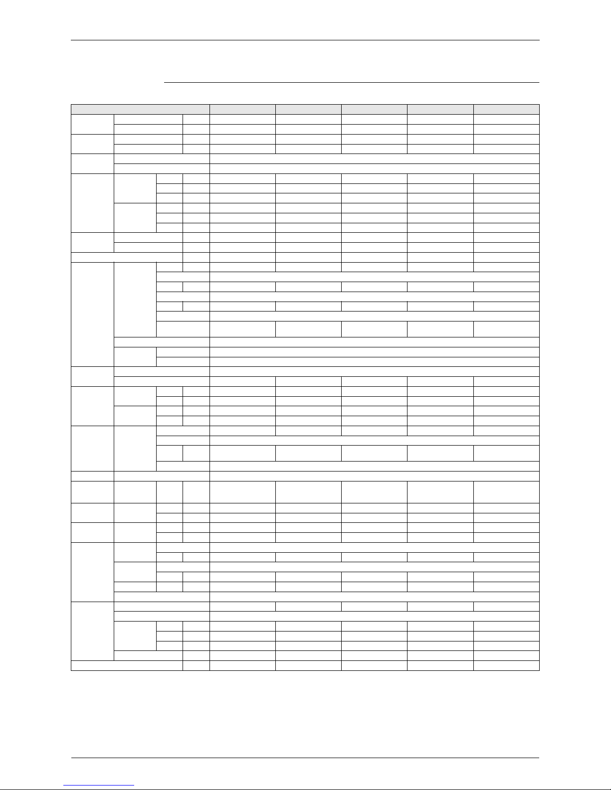
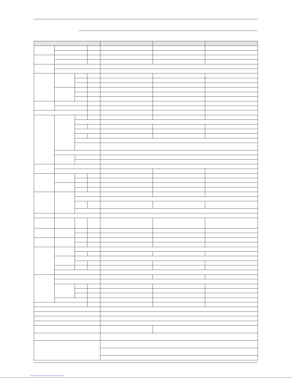
1.1 Outdoor Units
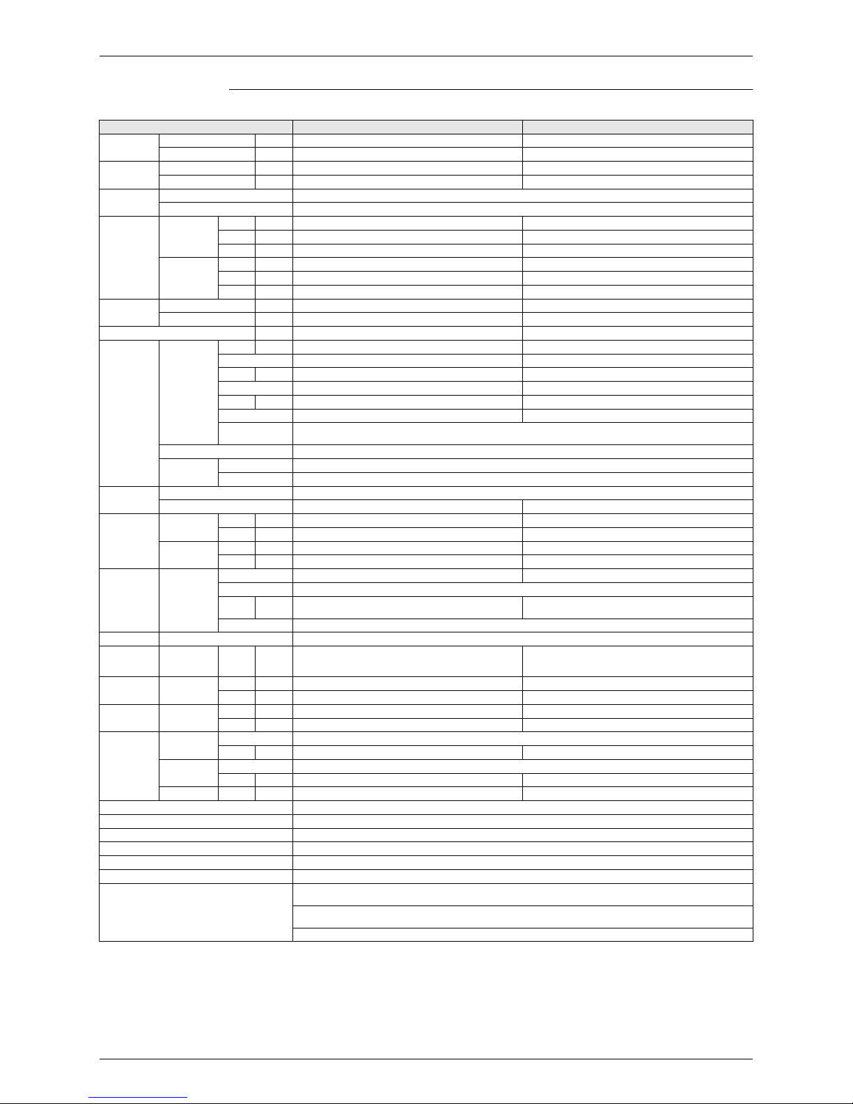
Heat Pump 50Hz <U-4..6ML5XPQ>
1-1 TECHNICAL SPECIFICATIONS U-4ML5XPQ U-5ML5XPQ U-6ML5XPQ
Capacity
Cooling kW 11.2 14.0 15.5
Heating kW 12.5 16.0 18.0
COP
Cooling 3.88 3.88 3.33
Heating 4.43 4.03 3.83
Capacity range HP 4 5 6
PED category Category I
Max n° of indoor units to be connected 6 8 9
Indoor index
connection
Minimum 50 62.5 70
Maximum 130 162.5 182
Casing
Colour White
Material Painted galvanised steel
Dimensions
Packing
Height mm 1,524
Width mm 980 980 980
Depth mm 420 420 420
Unit
Height mm 1,345
Width mm 900 900 900
Depth mm 320 320 320
Weight
Unit kg 120 120 120
Packed Unit kg 130 130 130
Packing
Material Carton, wood + EPS
Weight kg 8 8 8
Heat
Exchanger
Dimensions
Length mm 857 857 857
Nr of Rows 2 2 2
Fin Pitch
mm 2 2 2
Nr of Passes101010
Face Area
m² 1,131
Nr of Stages 60 60 60
Tube type Hi-XSS (8)
Fin
Fin type Non-sy mmetric w a ffle lo u v re
Treatment Corrosion resistant
Fan
Type Propeller
Quantity 2 2 2
Air Flow Rate
(nominal at 230V)
Cooling m³/min 106 106 106
Heating m³/min 102 105 105
Discharge direction Horizontal
Motor
Quantity 2 2 2
Model Brushless DC motor
Motor
Speed
(nominal)
Cooling rpm 850/815
Heating rpm 820/785 840/805 840/805
Fan Motor
Drive Direct d riv e
Output motor
W707070
Compressor
Quantity 1 1 1
Motor
Quantity 1 1 1
Model JT100G-VDLYR
Type Hermetically sealed scroll compressor
Speed rpm 6,480
Motor Output
kW 2.5 3.0 3.5
Starting Method Direct on line
Crankcase
Heater
W333333
Cooling Standard M in °CDB -5 -5 -5
Operation
Range
Cooling Max °CDB 46 46 46
Heating
Min °CWB -20 -20 -20
Max °CWB 15.5 15.5 15.5
Urban Multi ML5 · Mini UM · Heat Pump

Specifications
Specifications 7
1-1 TECHNICAL SPECIFICATIONS U-4ML5XPQ U-5ML5XPQ U-6ML5XPQ
Sound level
Coolin g
Sound Power
(Nominal)
dBA666769
Sound
Pressure
(Nominal)
dBA505153
Heating
Sound
Pressure
(Nominal)
dBA525355
Refrigerant
Name R-410A
Charge kg 4.0 4.0 4.0
Control Expansion valve (electronic type)
Nr of Circuits 1 1 1
Refrigerant
Oil
Name Daphne FVC68D
Charged Volume l 1.5 1.5 1.5
Piping
connections
Liquid
(OD)
Type Flare connection
Diameter
(OD)
mm 9.52 9.52 9.52
Gas
Type Flare connection Flare connection Braze connection
Diameter
(OD)
mm 15.9 15.9 19.1
Drain
Quantity 3 3 3
Diameter
(OD)
mm 26 × 3
Heat Insulation Both liquid and gas pipes
Max total length m 300 300 300
Defrost Method Reversed cycle
Defrost Control Sensor for outdoor heat exchanger temperature
Capacity Control Method Inverter controlled
Capacity Control 24 to 100
Safety devices HPS, Fan motor thermal protection, Inverter overload protector, PC board fuse
Standard Accessories Installation manual, Operation manual
Installation manual, Operation manual,
Connection pipes
Notes
Nominal cooling capacities are based on : indoor temperature : 27°CDB, 19°CWB, outdoor temperature : 35°CDB,
equivalent refrigerant piping : 5m, level difference : 0m.
Nominal heating capacities are based on: indoor temperature: 20°CDB, outdoor temperature: 7°CDB, 6°CWB, equivalent
refrigerant piping: 5m, level difference: 0m.
Sound power level is an absolute value that a sound source generates.
Sound pressure level is a relative value, depending on the distance and acoustic environment. For m ore details, please
refer to sound level drawings.
Sound values are measured in a semi-anechoic room.
Panasonic
Specifications
8 Specifications
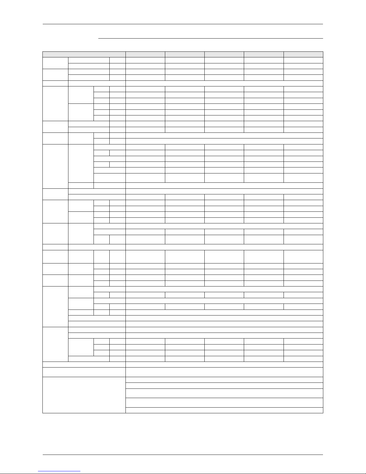
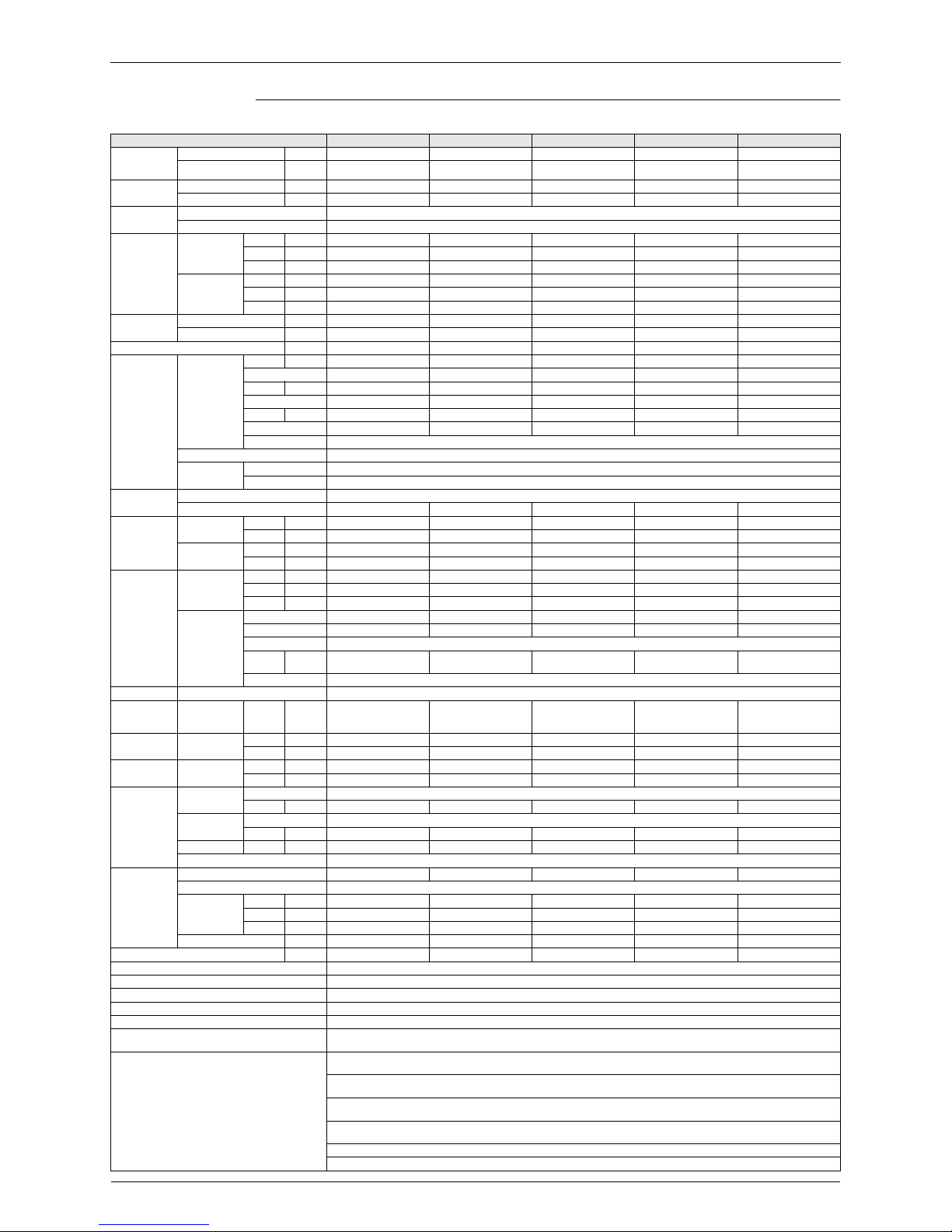
Heat pump 50Hz <U-4..6ML5DPQ>
1-1 TECHNICAL SPECIFICATIONS U-4ML5DPQ U-5ML5DPQ U-6ML5DPQ
Capacity
Cooling kW 11.2 14.0 15.5
Heating kW 12.5 16.0 18.0
COP
Cooling 3.99 3.99 3.42
Heating 4.56 4.15 3.94
Capacity range HP 4 5 6
PED category Category I
Max n° of indoor units to be connected 6 8 9
Indoor index
connection
Minimum 50 62.5 70
Maximum 130 162.5 182
Casing
Colour White
Material Painted galvanised steel
Dimensions
Packing
Height mm 1,524
Width mm 980 980 980
Depth mm 420 420 420
Unit
Height mm 1,345
Width mm 900 900 900
Depth mm 320 320 320
Weight
Unit kg 120 120 120
Packed Unit kg 130 130 130
Packing
Material Carton, wood + EPS
Weight kg 8 8 8
Heat
Exchanger
Dimensions
Length mm 857 857 857
Nr of Rows 2 2 2
Fin Pitch
mm 2 2 2
Nr of Passes101010
Face Area
m² 1,131
Nr of Stages 60 60 60
Tube type Hi-XSS (8)
Fin
Fin type Non-sy mmetric w a ffle lo u v re
Treatment Corrosion resistant
Fan
Type Propeller
Quantity 2 2 2
Air Flow Rate
(nominal at 230V)
Cooling m³/min 106 106 106
Heating m³/min 102 105 105
Discharge direction Horizontal
Motor
Quantity 2 2 2
Model Brushless DC motor
Motor
Speed
(nominal)
Cooling rpm 850/815
Heating rpm 820/785 840/805 840/805
Fan Motor
Drive Direct d riv e
Output motor
W707070
Compressor
Quantity 1 1 1
Motor
Quantity 1 1 1
Model JT100G-VDL
Type Hermetically sealed scroll compressor
Speed rpm 6,480
Motor Output
kW 2.5 3.0 3.5
Starting Method Direct on line
Crankcase
Heater
W333333
Cooling Standard Min °CDB -5 -5 -5
Operation
Range
Cooling Max °CDB 46 46 46
Heating
Min °CWB -20 -20 -20
Max °CWB 15.5 15.5 15.5
Sound Level
Coolin g
Sound Power
dBA666769
Sound Pressure
dBA505153
Heating
Sound Pressure
dBA525355
Urban Multi ML5 · Mini UM · Heat Pump
Specifications
Specifications 9
1-1 TECHNICAL SPECIFICATIONS U-4ML5DPQ U-5ML5DPQ U-6ML5DPQ
Refrigerant
Name R-410A
Charge kg 4.0 4.0 4.0
Control Expansion valve (electronic type)
N× of circu its 1 1 1
Refrigerant
Oil
Name Daphne FVC68D
Charged Volume l 1.5 1.5 1.5
Piping
connections
Liquid
(OD)
Type Flare connection
Diameter
(OD)
mm 9.52 9.52 9.52
Gas
Type Flare connection Flare connection Braze connection
Diameter
(OD)
mm 15.9 15.9 19.1
Drain
Quantity 3 3 3
Diameter
(OD)
mm 26 × 3
Heat Insulation Both liquid and gas pipes
Max total length m 300 300 300
Defrost Method Reversed cycle
Defrost Control Sensor for outdoor heat exchanger temperature
Capacity Control Method
Capacity Control
Inverter controlled
24 to 100
Safety devices HPS, Fan motor thermal protection, Inverter overload protector, PC board fuse
Standard Accessories Installation manual, Operation manual
Installation manual, Operation manual,
Connection pipes
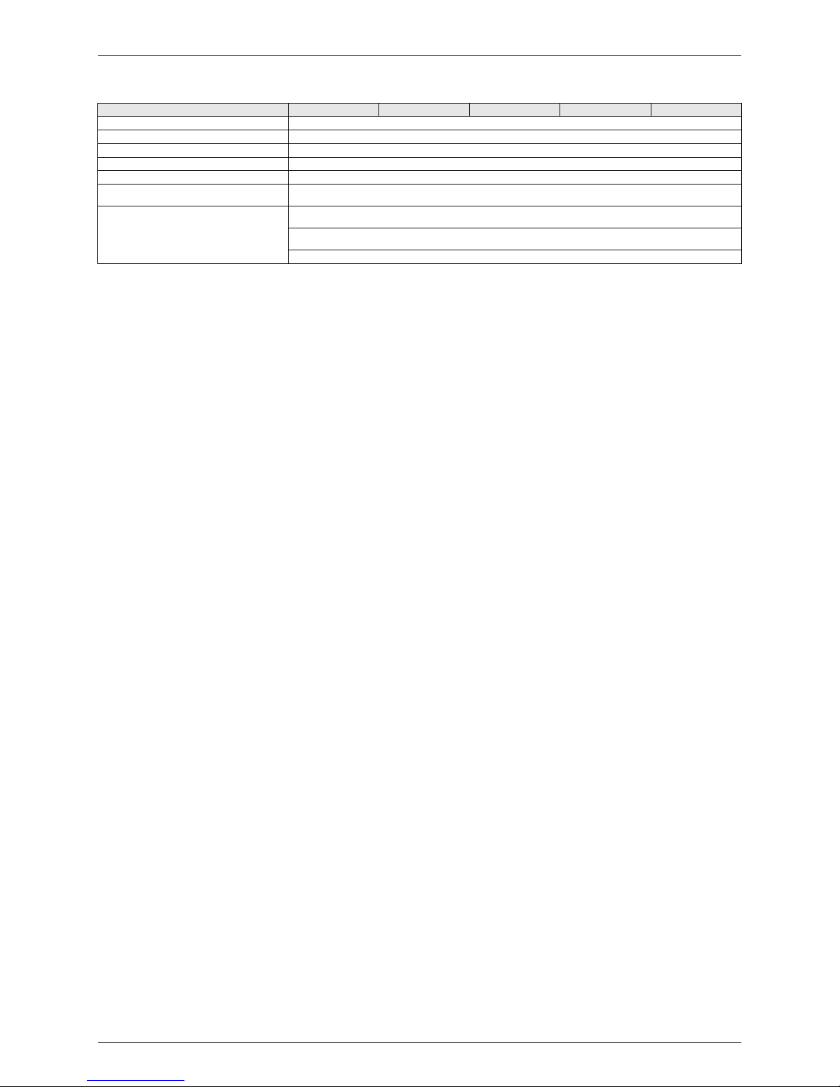
Notes
Nominal cooling capacities are based on : indoor temperature : 27°CDB, 19°CWB, outdoor temperature : 35°CDB,
equivalent refrigerant piping : 5m, level difference : 0m.
8 meter 1
Sound pressure
Sound values
Sound values are measured in a semi-anechoic room.
Panasonic
Specifications
10 Specifications
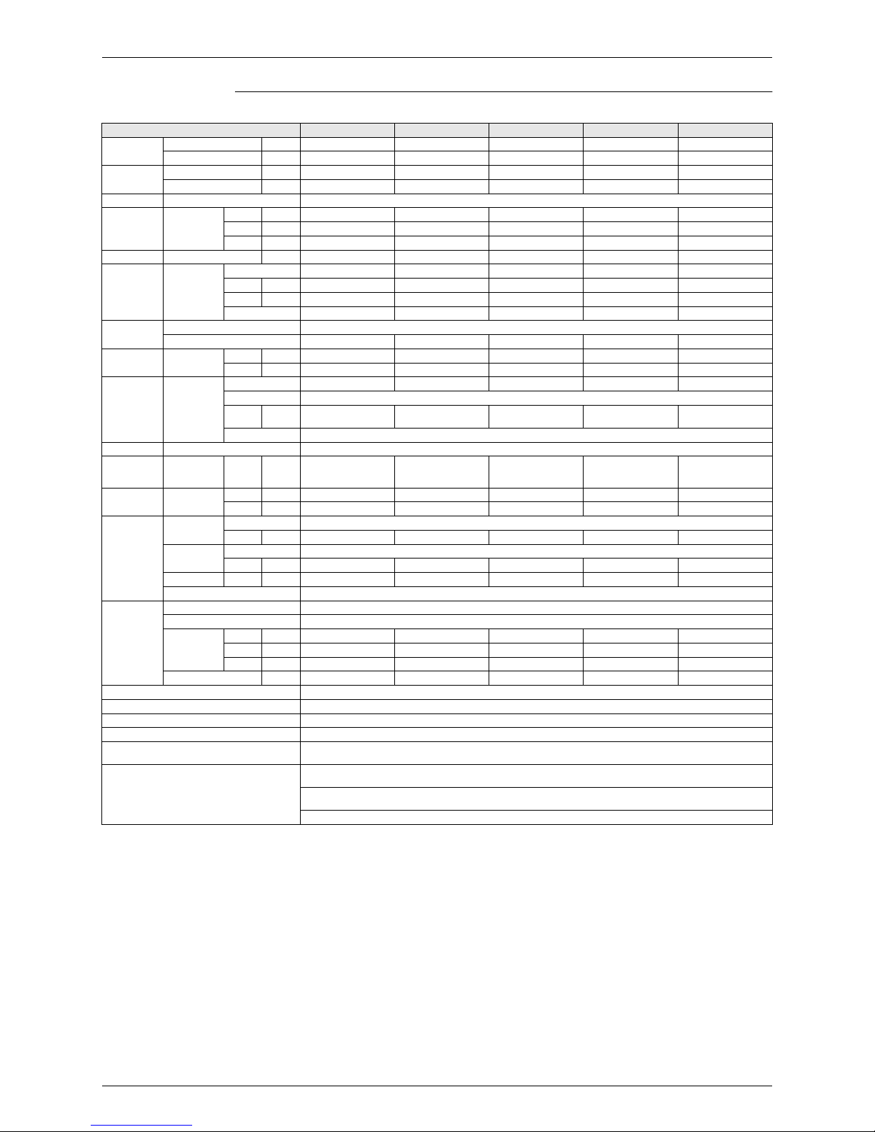
1.2 Indoor Units
Ceiling Mounted Cassette Type (Double Flow)
1-1 TECHNICAL SPECIFICATIONS S-20LM3HPQ S-25LM3HPQ S-32LM3HPQ S-40LM3HPQ S-50LM3HPQ
Nominal
Capacity
Cooling kW 2.20 2.80 3.60 4.50 5.60
Heating kW 2.50 3.20 4.0 0 5.00 6.30
Power input
(Nominal)
Cooling kW 0.077 0.092 0.092 0.130 0.130
Heating kW 0.044 0.059 0.059 0.097 0.097
Casing
Colour Non painted
Material Galvanised steel
Dimensions
Packing
Height mm 405 405 405 405 405
Width mm 1060 1060 1060 1280 1280
Depth mm 665 665 665 665 665
Unit
Height mm 305 305 305 305 305
Width mm 780 780 780 995 995
Depth mm 600 600 600 600 600
Weight
Unit kg 26 26 26 31 32
Packed Unit kg 30 30 30 37 38
Required Ceiling Void mm 350 350 350 350 350
Heat
Exchanger
Dimensions
Length mm 475×2 475×2 475×2 690×2 475×2
Nr of Rows 2×2
Fin Pitch
mm 1.50 1.50 1.50 1.50 1.50
Nr of Passes 3×2
Face Area
m² 0.1×2 0.1×2 0.1×2 0.145×2 0.145×2
Nr of Stages 10×2
Empty Tubeplate
Hole
6
Tube type Hi-XSS (7)
Fin
Fin type Symmetric waffle lo u v re
Treatment Hydrophilic
Fan
Type Sirocco fan
Quantity 11122
Air Flow R a te
Coolin g
High m³/m in 7.0 9.0 9.0 12.0 12.0
Low m³/m in 5.0 6.5 6.5 9.0 9.0
Heating
High m³/m in 7.0 9.0 9.0 12.0 12.0
Low m³/m in 5.0 6.5 6.5 9.0 9.0
Fan Motor
Quantity11111
Steps Phase cut control
Output
(high)
W1015152020
Drive Direct d riv e
Refrigerant Name R-410A
Sound Level Cooling
Sound
power
(nominal)
dBA 45.0 50.0 50.0 50.0 50.0
Coolin g
Sound
Pressure
High dBA 33.0 35.0 35.0 35.5 35.5
Low dBA 28.0 29.0 29.0 30.5 30.5
Heating
Sound
Pressure
High dBA 33.0 35.0 35.0 35.5 35.5
Low dBA 28.0 29.0 29.0 30.5 30.5
Piping
connections
Liquid (OD)
Type Flare connection
Diameter
mm 6.35 6.35 6.35 6.35 6.35
Gas
Type Flare connection
Diameter
mm 12.7 12.7 12.7 12.7 12.7
Drain
Diameter
mm 32 32 32 32 32
Heat Insulation Both liquid and gas pipes
Decoration
Panel
ModelCZ-01KPL11P CZ-01KPL11P CZ-01KPL11P CZ-02KPL11P CZ-02KPL11P
Colour White (10Y9/0,5)
Dimensions
Height mm 53 53 53 53 53
Width mm 1030 1030 1030 1245 1245
Depth mm 680 680 680 680 680
Weight kg 8.0 8.0 8 .0 8.5 8.5
Drain-up Height mm 600 600 600 600 600
Urban Multi ML5 · Mini UM · Heat Pump
Specifications
Specifications 11
1-1 TECHNICAL SPECIFICATIONS S-20LM3HPQ S-25LM3HPQ S-32LM3HPQ S-40LM3HPQ S-50LM3HPQ
Air Filter Resin net with mold resistance
Air direction control Up and downwards
Refrigerant control Electronic expansion valve
Temperature control M icroprocessor thermostat for cooling and heating
Safety devices PC board fuse, Fan motor thermal fuse, Drain pump fuse
Standard Accessories
Screws for fixing the paper pattern for installation, Washer for hanging bracket, Installation and operation manual, Paper
pattern fo r in sta lla tio n , In s u la tio n fo r fittin g , D r a in h o se
Notes
Nominal cooling capacities are based on : indoor temperature : 270CDB, 190CW B , outdoor temperature : 350CDB,
equivalent refrigerant piping : 8m, level difference : 0m.
Nominal heating capacities are based on : indoor temperature : 200CDB, outdoor temperature : 70CDB, 60CWB,
equivalent refrigerant piping : 8m, level difference : 0m.
Capacities are net, including a deduction for cooling (an addition for heating) for indoor fan motor heat.
Panasonic
Specifications
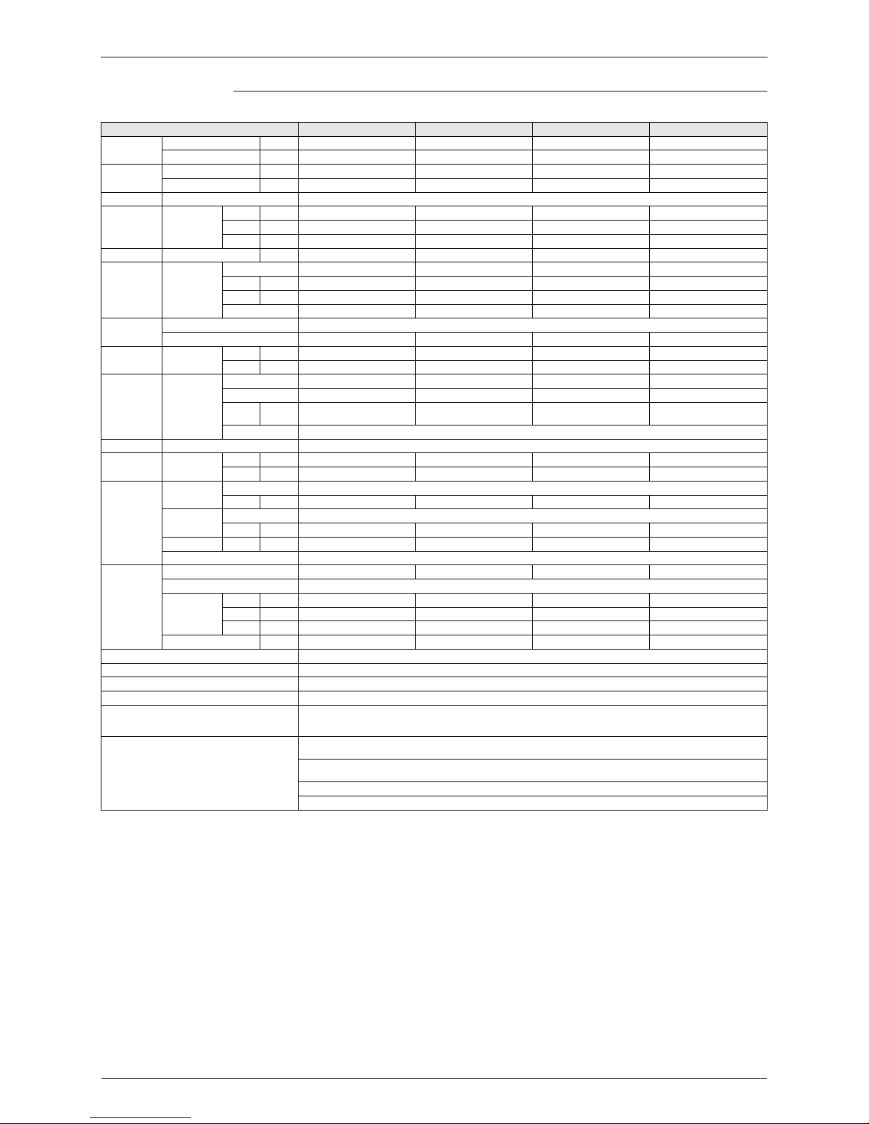
12 Specifications
Ceiling Mounted Cassette Type (Double Flow)
1-1 TECHNICAL SPECIFICATIONS S-63LM3HPQ S-80LM3HPQ S-125LM3HPQ
Nominal
Capacity
Cooling kW 7.10 9.00 14.00
Heating kW 8.00 10.00 16.00
Power input
(Nominal)
Cooling kW 0.161 0.209 0.256
Heating kW 0.126 0.176 0.223
Casing
Colour Non painted
Material Galvanised steel
Dimensions
Packing
Height mm 405 405 405
Width mm 1460 1808 1808
Depth mm 665 645 645
Unit
Height mm 305 305 305
Width mm 1180 1670 1670
Depth mm 600 600 600
Weight
Unit kg 35 47 48
Packed Unit kg 42 55 56
Required Ceiling Void mm 350 350 350
Heat
Exchanger
Dimensions
Length mm 875×2 1365 1365
Nr of Rows 2×2
Fin Pitch
mm 1.50 1.50 1.50
Nr of Passes 6×2 5×2 6
Face Area
m² 0.184×2 0.287×2 0.287×2
Nr of Stages 10×2
Empty Tubeplate
Hole
8
Tube type Hi-XSS (7)
Fin
Fin type Symmetric waffle lo u v re
Treatment Hydrophilic
Fan
Type Sirocco fan
Quantity 2 3 3
Air Flow R a te
Coolin g
High m³/m in 16.5 26.0 33.0
Low m³/m in 13.0 21.0 25.0
Heating
High m³/m in 16.5 26.0 33.0
Low m³/m in 13.0 21.0 25.0
Fan Motor
Quantity 1 1 1
Steps Phase cut control
Output
(high)
W305085
Drive Direct d riv e
Refrigerant Name R-410A
Sound Level Cooling
Sound
power
(nominal)
dBA 52.0 54.0 60.0
Coolin g
Sound
Pressure
High dBA 38.0 40.0 45.0
Low dBA 33.0 35.0 39.0
Heating
Sound
Pressure
High dBA 38.0 40.0 45.0
Low dBA 33.0 35.0 39.0
Piping
connections
Liquid (OD)
Type Flare connection
Diameter
mm 9.5 9.5 9.5
Gas
Type Flare connection
Diameter
mm 15.9 15.9 15.9
Drain
Diameter
mm 32 32 32
Heat Insulation Both liquid and gas pipes
Decoration
Panel
ModelCZ-03KPL11P CZ-06KPL11P CZ-06KPL11P
Colour White (10Y9/0,5)
Dimensions
Height mm 53 53 53
Width mm 1430 1920 1920
Depth mm 680 680 680
Weight kg 9.5 12.0 12.0
Drain-up Height mm 600 600 600
Air Filter Resin net with mold resistance
Air direction control Up and downwards
Refrigerant control Electronic expansion valve
Temperature control M icroprocessor thermostat for cooling and heating
Safety devices
PC board fuse, Fan motor thermal fuse,
Drain pump fuse
PC board fuse, Fan motor thermal protector, Drain pump fuse
Standard Accessories
Screws for fixing the paper pattern for installation, Washer for hanging bracket, C lamps, Installation and operation manual,
Paper pattern for installation, Insulation for fitting, Drain hose
Notes
Nominal cooling capacities are based on : indoor temperature : 27°CDB, 19°CWB, outdoor temperature : 35°CDB,
equivalent refrigerant piping : 8m, level difference : 0m.
Nominal heating capacities are based on : indoor temperature : 20°CDB, outdoor temperature : 7°CDB, 6°CWB,
equivalent refrigerant piping : 8m, level difference : 0m.
Capacities are net, including a deduction for cooling (an addition for heating) for indoor fan motor heat.
Urban Multi ML5 · Mini UM · Heat Pump
Specifications
Specifications 13
Ceiling Mounted Cassette Type (Round-flow)
1-1 TECHNICAL SPECIFICATIONS S-20UM4JPQ S-25UM4JPQ S-32UM4JPQ S-40UM4JPQ S-50UM4JPQ
Capacity
Cooling kW 2.2 2.8 3.6 4.5 5.6
Heating kW 2.5 3.2 4.0 5.0 6.3
Power Input
Cooling kW 0.053 0.053 0.053 0.063 0.083
Heating kW 0.045 0.045 0.045 0.055 0.067
Casing Material Galvanised steel
Dimensions
Packing
Height mm 220 220 220 220 220
Width mm 882 882 882 882 882
Depth mm 882 882 882 882 882
Unit
Height mm 204 204 204 204 204
Width mm 840 840 840 840 840
Depth mm 840 840 840 840 840
Weight
Unit kg 20.0 20.0 20.0 20.0 21.0
Packed Unit kg 24.0 24.0 24.0 24.0 26.0
Dimensions Length
Inside mm 2,096
Outside mm 2,152
Heat
Exchanger
Dimensions
Nr of Rows 2 2 2 2 2
Fin Pitch
mm 1.2 1.2 1.2 1.2 1 .2
Nr of Passes 2 2 3 3 7
Face Area
m² 0.267 0.267 0.267 0.267 0.357
Nr of Stages 6 6 6 6 8
Empty Tubeplate
Hole
44
Fin Fin type Cross fin coil (Multi louver fins and Hi-XSS tubes)
Fan
Type Turbo fan
Quantity 11111
Air Flow R a te
Coolin g
High m³/m in 12.5 12.5 12.5 13.5 15.5
Low m³/m in 9.0 9.0 9.0 9.0 10.0
Heating
High m³/m in 12.5 12.5 12.5 13.5 15.0
Low m³/m in 9.0 9.0 9.0 9.0 9.5
Fan Motor
Model QTS48D11M
Steps 22222
Output
(high)
W5656565656
Refrigerant Name R-410A
Sound Level Cooling
Sound
power
(nominal)
dBA4949495051
Coolin g
Sound
Pressure
High dBA 31 31 31 32 33
Low dBA 28 28 28 28 28
Heating
Sound
Pressure
High dBA 31 31 31 32 33
Low dBA 28 28 28 28 28
Piping
connections
Liquid (OD)
Type Flare connection
Diameter
mm 6.35 6.4 6.4 6.4 6.4
Gas
Type Flare connection
Diameter
mm 12.7 12.7 12.7 12.7 12.7
Drain
Diameter
mm VP25 (I.D. 25/O.D . 32 )
Heat Insulation Foamed polystyrene/polyethylene
Sound absorbing insulation (Foamed Polyurethane)
Decoration
Panel
ModelCZ-06KPU12P
Colour RAL9010
Dimensions
Height mm 50 50 50 50 50
Width mm 950 950 950 950 950
Depth mm 950 950 950 950 950
Weight kg 5.5 5.5 5 .5 5.5 5.5
Air Filter Resin net with mold resistance
Standard Accessories
Installation and operation manual, Drain hose, W asher for hanging bracket, Screws, Sealing Pads, Insulation for fitting,
Clamp for drain hose, Installation guide, Drain sealing pad
Notes
The sound pressure values are mentioned for a unit installed w ith rear suction
The sound power level is an absolute value indicating the power wich a sound source generates.
Nominal cooling capacities are based on : indoor temperature : 27°CDB, 19°CWB, outdoor temperature : 35°CDB,
equivalent refrigerant piping : 5m, level difference : 0m.
Nominal heating capacities are based on : indoor temperature : 20°CDB, outdoor temperature : 7°CDB, 6°CWB,
equivalent refrigerant piping : 5m (horizontal)
Capacities are net, including a deduction for cooling (an addition for heating) for indoor fan motor heat.
Panasonic

Specifications
14 Specifications
Ceiling Mounted Cassette Type (Round-flow)
1-1 TECHNICAL SPECIFICATIONS S-63UM4JPQ S-80UM4JPQ S-100UM4JPQ S-125UM4JPQ
Capacity
Cooling kW 7.1 9.0 11.2 14.0
Heating kW 8.0 10.0 12.5 16.0
Power Input
Cooling kW 0.095 0.120 0.173 0.258
Heating kW 0.114 0.108 0.176 0.246
Casing Material Galvanised steel
Dimensions
Packing
Height mm 220 262 262 304
Width mm 882 882 882 882
Depth mm 882 882 882 882
Unit
Height mm 204 246 246 288
Width mm 840 840 840 840
Depth mm 840 840 840 840
Weight
Unit kg 21.0 24.0 24.0 26.0
Packed Unit kg 26.0 28.0 28.0 31.0
Dimensions Length
Inside mm 2,096
Outside mm 2,152
Heat
Exchanger
Dimensions
Nr of Rows 2 2 2 2
Fin Pitch
mm 1.2 1.2 1.2 1.2
Nr of Passes 7 9 9 11
Face Area
m² 0.357 0.446 0.446 0.535
Nr of Stages 8 10 10 12
Fin Fin type Cross fin coil (Multi louver fins and Hi-XSS tubes)
Fan
Type Turbo fan
Quantity 1 1 1 1
Air Flow R a te
Coolin g
High m³/m in 16.5 23.5 26.5 33.0
Low m³/m in 11.0 14.5 17.0 20.0
Heating
High m³/m in 17.5 23.5 28.0 33.0
Low m³/m in 12.0 14.5 17.5 20.0
Fan Motor
Model QTS48D11M QTS48C15M QTS48C15M QTS48C15M
Steps 2 2 2 2
Output
(high)
W 56 120 120 120
Refrigerant Name R-410A
Sound Level Cooling
Sound
power
(nominal)
dBA52555861
Coolin g
Sound
Pressure
High dBA 34 38 41 44
Low dBA 29 32 33 34
Heating
Sound
Pressure
High dBA 36 38 42 44
Low dBA 30 32 34 34
Piping
connections
Liquid (OD)
Type Flare connection
Diameter
mm 9.5 9.5 9.5 9.5
Gas
Type Flare connection
Diameter
mm 15.9 15.9 15.9 15.9
Drain
Diameter
mm VP25 (I.D. 25/O.D . 32 )
Heat Insulation Foamed polystyrene/polyethylene
Sound absorbing insulation (Foamed Polyurethane)
Decoration
Panel
ModelCZ-06KPU12P
Colour RAL9010
Dimensions
Height mm 50 50 50 50
Width mm 950 950 950 950
Depth mm 950 950 950 950
Weight kg 5.5 5.5 5.5 5.5
Air Filter Resin net with mold resistance
Standard Accessories
Installation and operation manual, Drain hose, W asher for hanging bracket, Screws, Sealing Pads, Insulation for fitting,
Clamp for drain hose, Installation guide, Drain sealing pad
Notes
The sound pressure values are mentioned for a unit installed w ith rear suction
The sound power level is an absolute value indicating the power wich a sound source generates.
Nominal cooling capacities are based on : indoor temperature : 27°CDB, 19°CWB, outdoor temperature : 35°CDB,
equivalent refrigerant piping : 5m, level difference : 0m.
Nominal heating capacities are based on : indoor temperature : 20°CDB, outdoor temperature : 7°CDB, 6°CWB,
equivalent refrigerant piping : 5m (horizontal)
Capacities are net, including a deduction for cooling (an addition for heating) for indoor fan motor heat.
Urban Multi ML5 · Mini UM · Heat Pump
Specifications
Specifications 15
600×600 Ceiling Mounted Cassette Type (Multi Flow)
1-1 TECHNICAL SPECIFICATIONS S-20YM3HPQ S-25YM3HPQ S-32YM3HPQ S-40YM3HPQ S-50YM3HPQ
Nominal
Capacity
Cooling kW 2.20 2.80 3.60 4.50 5.60
Heating kW 2.50 3.20 4.00 5.00 6.30
Power input
(Nominal)
Cooling kW 0.073 0.073 0.076 0.089 0.115
Heating kW 0.064 0.064 0.068 0.080 0.107
Casing Material Galvanised steel
Dimensions Unit
Height mm 286 286 286 286 286
Width mm 575 575 575 575 575
Depth mm 575 575 575 575 575
Weight Unit kg 18 18 18 18 18
Heat
Exchanger
Dimensions
Nr of Rows 2 2 2 2 2
Fin Pitch
mm 1.50 1.50 1.50 1.50 1.50
Face Area
m² 0.269 0.269 0.269 0.269 0.269
Nr of Stages 10 10 10 10 10
Fan
Type Turbo fan
Quantity 11111
Air Flow Rate Coolin g
High m³/m in 9.00 9.00 9.50 11.00 14.00
Low m³/m in 7.00 7.00 7.50 8.00 10.00
Fan Motor
Quantity11111
Model QTS32C15M
Output
(high)
W5555555555
Drive Direct d riv e
Refrigerant Name R-410A
Sound Level Cooling
Sound
power
(nominal)
dBA 47.0 47.0 49.0 53.0 58.0
Coolin g
Sound
Pressure
High dBA 30.0 30.0 32.0 36.0 41.0
Low dBA 25.0 25.0 26.0 28.0 33.0
Piping
connections
Liquid (OD)
Type Flare connection
Diameter
mm 6.4 6.4 6.4 6.4 6 .4
Gas
Type Flare connection
Diameter
mm 12.7 12.7 12.7 12.7 12.7
Drain
Diameter
mm 26 26 26 26 26
Heat Insulation Foamed polystyrene/polyethylene
Decoration
Panel
ModelCZ-02KPY12P
Colour White (Ral 9010)
Dimensions
Height mm 55 55 55 55 55
Width mm 700 700 700 700 700
Depth mm 700 700 700 700 700
Weight kg 2.7 2.7 2 .7 2.7 2.7
Air Filter Resin net with mold resistance
Refrigerant control Electronic expansion valve
Temperature control M icroprocessor thermostat for cooling and heating
Safety devices PC board fuse, Fan motor thermal protector
Standard Accessories
Installation and operation manual, Paper pattern for installation, Drain hose, Clamp metal, Washer fixing plate,
Sealing Pads, Clamps, Screws, Washer for hanger bracket, Insulation for fitting
Notes
Nominal cooling capacities are based on : indoor temperature : 27°CDB, 19°CWB, outdoor temperature : 35°CDB,
equivalent refrigerant piping : 7,5m (horizontal)
Nominal heating capacities are based on : indoor temperature : 20°CDB, outdoor temperature : 7°CDB, 6°CWB,
equivalent refrigerant piping : 7.5m (horizontal)
Capacities are net, including a deduction for cooling (an addition for heating) for indoor fan motor heat.
Panasonic
Specifications
16 Specifications
Ceiling Mounted Cassette Corner Type
1-1 TECHNICAL SPECIFICATIONS S-25DM3HPS S-32DM3HPS S-40DM3HPS S-63DM3HPS
Nominal
Capacity
Cooling kW 2.80 3.60 4.50 7.10
Heating kW 3.20 4.00 5.00 8.00
Power input
(Nominal)
Cooling kW 0.066 0.066 0.076 0.105
Heating kW 0.046 0.046 0.056 0.085
Casing Material Galvanised steel
Dimensions Unit
Height mm 215 215 215 215
Width mm 1110 1110 1110 1310
Depth mm 710 710 710 710
Weight Unit kg 31 31 31 34
Heat
Exchanger
Dimensions
Nr of Rows 2 2 2 3
Fin Pitch
mm 1.75 1.75 1.75 1.75
Face Area
m² 0.180 0.180 0.180 0.226
Nr of Stages 11 11 11 11
Fan
Type
Sirocco fan
Quantity 1 1 1 1
Air Flow Rate Coolin g
High m³/m in 11.00 11.00 13.00 18.00
Low m³/m in 9.00 9.00 10.00 15.00
Fan Motor
Quantity 1 1 1 1
Model 3D12H1AN1V1 3D12H1AN1V1 3D12H1AP1V1 4D12H1AJ1V1
Output
(high)
W15152045
Drive Direct d riv e
Refrigerant Name R-410A
Coolin g
Sound
Pressure
High dBA 38.0 38.0 40.0 42.0
Low dBA 33.0 33.0 34.0 37.0
Piping
connections
Liquid (OD)
Type Flare connection
Diameter
mm 6.4 6.4 6.4 9.5
Gas
Type Flare connection
Diameter
mm 12.7 12.7 12.7 15.9
Drain
Diameter
mm 32 32 32 32
Heat Insulation Foamed Polyethylene
Decoration
Panel
ModelCZ-02KPD11P CZ-02KPD11P CZ-02KPD11P CZ-03KPD11P
Colour
White
Dimensions
Height mm 70 70 70 70
Width mm 1240 1240 1240 1440
Depth mm 800 800 800 800
Weight kg 8.5 8.5 8.5 9.5
Air Filter Resin net with mold resistance
Refrigerant control Electronic expansion valve
Temperature control M icroprocessor thermostat for cooling and heating
Safety devices PC board fuse, Drain pump fuse, Fan motor thermal
Standard Accessories
Installation and operation manual, Metal clam p for drain hose, Clamps, Insulation for hangar bracket,
Positioning Jig for Installation, Paper pattern for installation, Drain hose, Insulation for fitting, Sealing Pads, Screws,
Washer, Air Outlet blocking pad
Notes
Nominal cooling capacities are based on : indoor temperature : 27°CDB, 19°CWB, outdoor temperature : 35°CDB,
equivalent refrigerant piping : 7,5m (horizontal)
Nominal heating capacities are based on : indoor temperature : 20°CDB, outdoor temperature : 7°CDB, 6°CWB,
equivalent refrigerant piping : 7.5m (horizontal)
Capacities are net, including a deduction for cooling (an addition for heating) for indoor fan motor heat.
Sound pressure levels are m easured at 220V
Urban Multi ML5 · Mini UM · Heat Pump
Specifications
Specifications 17
Slim Ceiling Mounted Duct Type (with Drain Pump)
1-1 TECHNICAL SPECIFICATIONS S-20NM3HPQ S-25NM3HPQ
Nominal
Capacity
Cooling kW 2.20 2.80
Heating kW 2.50 3.20
Power input
(Nominal)
Cooling kW 0.050 0.050
Heating kW 0.050 0.050
Casing
Colour Non painted
Material Galvanised steel
Dimensions
Packing
Height mm 301 301
Width mm 584 584
Depth mm 753 753
Unit
Height mm 230 230
Width mm 502 502
Depth mm 652 652
Weight
Unit kg 17 17
Packed Unit kg 18 18
Required Ceiling Void mm 250 250
Heat
Exchanger
Dimensions
Length mm 430 430
Nr of Rows 2 2
Fin Pitch
mm 1.40 1.40
Nr of Passes 2 2
Face Area
m² 0.108 0.108
Nr of Stages 12 12
Empty Tubeplate
Hole
4
Tube type Hi-XSS (7)
Fin
Fin type Symmetric waffle lo u v re
Treatment Hydrophilic
Fan
Type Sirocco fan
Quantity 1 1
Air Flow R a te
Coolin g
High m³/m in 6.70 7.40
Low m³/m in 5.20 5.80
Heating
High m³/m in 6.70 7.40
Low m³/m in 5.20 5.80
Fan Motor
Quantity 1 1
Steps step motor
Output
(high)
W10 10
Drive Direct d riv e
Refrigerant Name R-410A
Sound Level Cooling
Sound
power
(nominal)
dBA 50.0 50.0
Coolin g
Sound
Pressure
High dBA 37.0 37.0
Low dBA 32.0 32.0
Heating
Sound
Pressure
High dBA 37.0 37.0
Low dBA 32.0 32.0
Piping
connections
Liquid (OD)
Type Flare connection
Diameter
mm 6.4 6.4
Gas
Type Flare connection
Diameter
mm 12.7 12.7
Drain
Diameter
mm 27.2 27.2
Air Filter Resin net with mold resistance
Air direction control Up and downwards
Refrigerant control Electronic expansion valve
Temperature control M icroprocessor thermostat for cooling and heating
Safety devices PC board fuse, Fan motor thermal protector
Standard Accessories Installation and operation manual, Fuse, Caution for servicing sticker, Suction air filter
Notes
Nominal cooling capacities are based on : indoor temperature : 27°CDB, 19°CWB, outdoor temperature : 35°CDB,
equivalent refrigerant piping : 8m, level difference : 0m.
Nominal heating capacities are based on : indoor temperature : 20°CDB, outdoor temperature : 7°CDB, 6°CWB,
equivalent refrigerant piping : 8m, level difference : 0m.
Capacities are net, including a deduction for cooling (an addition for heating) for indoor fan motor heat.
Panasonic
Specifications
18 Specifications
Ceiling Mounted Built-in Type
1-1 TECHNICAL SPECIFICATIONS S-20FM3HPQ S-25FM3HPQ S-32FM3HPQ S-40FM3HPQ S-50FM3HPQ
Capacity
(Conditions
specifie d in 1 )
Cooling kW 2.20 2.80 3.60 4.50 5.60
Heating kW 2.50 3.20 4.00 5.00 6.30
Power input
(Nominal)
Cooling kW 0.110 0.110 0.114 0.127 0.143
Heating kW 0.090 0.090 0.094 0.107 0.123
Casing
Colour Non painted
Material Galvanised steel
Dimensions
Packing
Height mm 354 354 354 354 354
Width mm 742 742 742 892 892
Depth mm 936 936 936 936 936
Unit
Height mm 300 300 300 300 300
Width mm 550 550 550 700 700
Depth mm 800 800 800 800 800
Weight
Unit kg 30 30 30 30 31
Packed Unit kg 34 34 34 34 35
Required Ceiling Void mm 350 350 350 350 350
Heat
Exchanger
Dimensions
Length mm 300 300 300 450 450
Nr of Rows 3 3 3 3 3
Fin Pitch
mm 1.75 1.75 1.75 1.75 1.75
Nr of Passes 3 3 3 4 4
Face Area
m² 0.088 0.088 0.088 0.132 0.132
Nr of Stages 14 14 14 14 14
Empty Tubeplate Hole
14
Tube type Hi-XSS (7)
Fin
Fin type Symmetric waffle lo u v re
Treatment Hydrophilic
Fan
Type Sirocco fan
Quantity 11111
Air Flow R a te
Coolin g
High m³/m in 9.00 9.00 9.50 11.50 15.00
Low m³/m in 6.50 6.50 7.00 9.00 11.00
Heating
High m³/m in 9.00 9.00 9.50 11.50 15.00
Low m³/m in 6.50 6.50 7.00 9.00 11.00
Fan
External static
pressure
High Pa 125 125 104 116 136
Standard
Pa 105 105 88 98 114
Low Pa 96 96 78 85 99
Motor
Quantity11111
Model D18H3AA1V1 D18H3AA1V1 D18H3AA1V1 D18H2AC1V1 D18H2AB1V1
Steps step motor
Output
(high)
W5050506585
Drive Direct d riv e
Refrigerant Name R-410A
Sound Level Cooling
Sound
power
(nominal)
dBA 50.0 50.0 51.0 56.0 58.0
Coolin g
Sound
Pressure
High dBA 32.0 32.0 33.0 33.0 35.0
Low dBA 28.0 28.0 28.0 29.0 31.0
Heating
Sound
Pressure
High dBA 32.0 32.0 33.0 33.0 35.0
Low dBA 28.0 28.0 28.0 29.0 31.0
Piping
connections
Liquid (OD)
Type Flare connection
Diameter
mm 6.35 6.35 6.35 6.35 6.35
Gas
Type Flare connection
Diameter
mm 12.7 12.7 12.7 12.7 12.7
Drain
Diameter
mm 32 32 32 32 32
Heat Insulation Both liquid and gas pipes
Decoration
Panel
ModelCZ-01HPF11P CZ-01HPF11P CZ-01HPF11P CZ-02HPF11P CZ-02HPF11P
Colour White (10Y9/0,5)
Dimensions
Height mm 55 55 55 55 55
Width mm 650 650 650 800 800
Depth mm 500 500 500 500 500
Weight kg 3 3 3 3.5 3.5
Drain-up Height mm 600 600 600 600 600
Air Filter Resin net with mold resistance
Air direction control Up and downwards
Refrigerant control Electronic expansion valve
Temperature control M icroprocessor thermostat for cooling and heating
Safety devices PC board fuse, Drain pump fuse, Fan motor therm al fuse
Standard Accessories
Metal clamp for drain hose, Paper pattern for installation, Drain hose, Insulation for fitting, Washer for hanger bracket,
Screws for duct flanges, Screws for fixing the paper pattern for installation, Fuse, Installation and operation manual
Notes
Nominal cooling capacities are based on : indoor temperature : 27°CDB, 19°CWB, outdoor temperature : 35°CDB,
equivalent refrigerant piping : 8m, level difference : 0m.
Nominal heating capacities are based on : indoor temperature : 20°CDB, outdoor temperature : 7°CDB, 6°CWB,
equivalent refrigerant piping : 8m, level difference : 0m.
The external static pressure is changeable : change the connectors inside the electrical box, this pressure means :
High static pressure -standard - low static pressure
The external static pressure is changeable : change the connectors inside the electrical box, this pressure means :
High static pressure -standard
Capacities are net, including a deduction for cooling (an addition for heating) for indoor fan motor heat.
The sound pressure values are mentioned for a unit installed w ith rear suction
Urban Multi ML5 · Mini UM · Heat Pump
 Loading...