

Panasonic TY-S42PX20U User Manual
Lift and
remove
Corner
protection pad
Support pole
(Left)
Assembly screws
(Black screws)
Support pole (Right)
(Back)
∗ Wire over the minimum distance
Power cord
Cord clamps
REPLACEMENT PARTS LIST
Part No.
TY-S50PX20U
TBLA0117
TBLH0550
TY-S42PX20U
Qty. Part No.
1 TBLA0116
1 TBLH0548
TBLA0104
TBLA0103
TBLB3110
1 TBLA0104
1 TBLA0103
1 TBLB3080
TKGA0129
TBLA3217
1 TKGA0127
1 TBLA3184
TQZH507 Printed in Japan
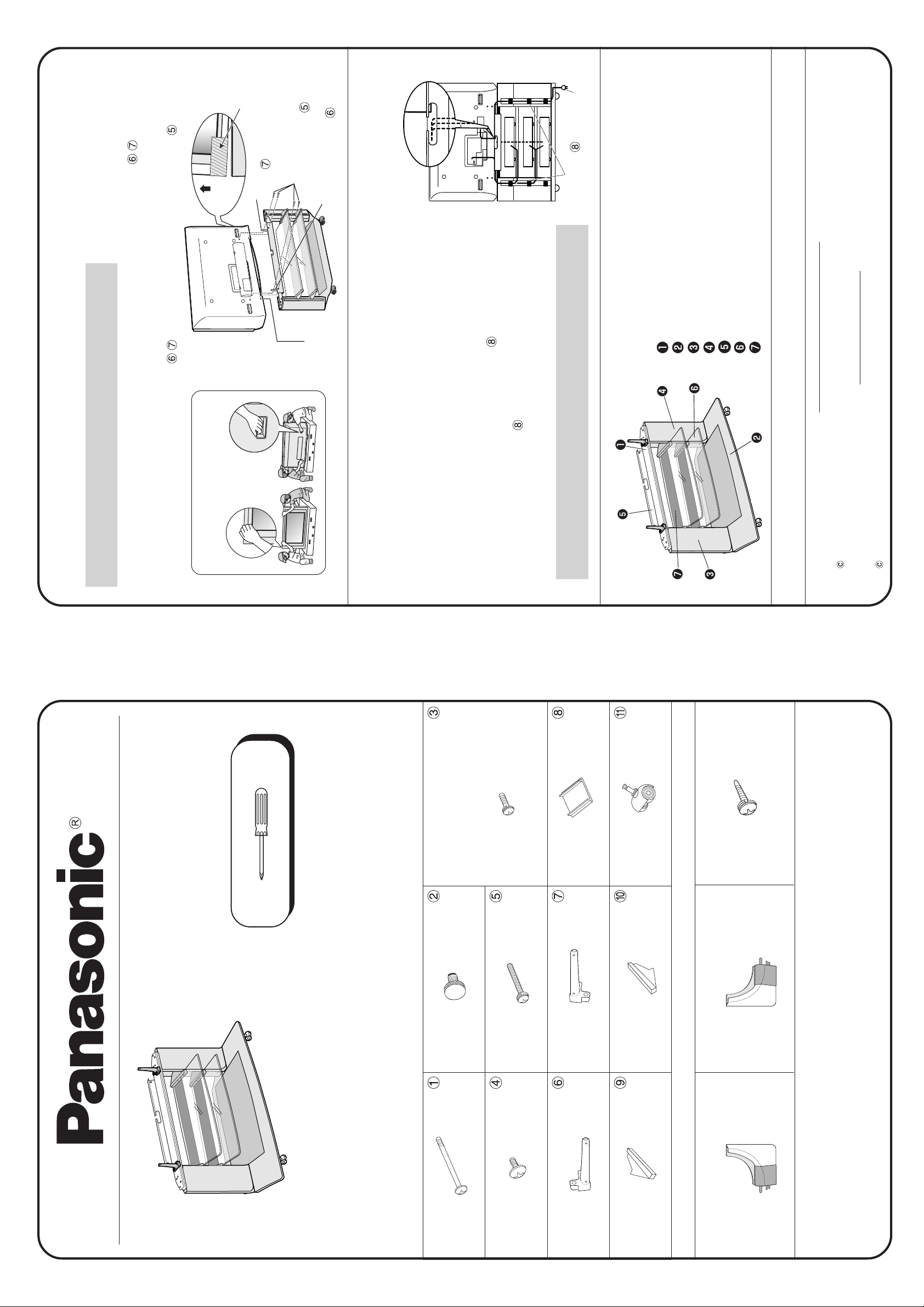
Plasma TV installation and fastening method
∗ Install the plasma TV by referring to the following illustration.
Placement
STEP 1
∗ Do not hold the plasma TV at the bottom of the front panel.
using assembly screws (black screws) (× 4)
Support pole
insertion hole
To use with equipment such as a video deck
points indicated in the illustration.
lower the plasma TV until the poles stop. Slightly lift the left and right sides of the plasma TV and
remove the corner protection pads attached to the bottom.
1. Align the support pole insertion holes of the plasma TV with the support poles (1 each), and
∗ Position by placing your hands at the
2. Fasten the plasma TV and support poles
STEP 2
Top crosspiece
Bottom panel
Ref. Description
left over, store them carefully. You will
amp. If you place a video deck here, it may badly affect the picture.
grooves in the rear cord cover, along the groves in the left and right
side panels, and along the groves in the cord holder under the glass
shelf.
the wiring over the minimum distance, as indicated by the dotted line in
the diagram.
• To thread wiring, remove the terminal cover and pass wires along the
∗ Some equipment may have short cords. In such an instance, thread
• After threading wiring, fasten with cord clamps (× 6) so that the cords
need them if you use the unit to house more equipment in the future.
do not protrude from the grooves. Finally, attach the terminal cover.
If there are any cord clamps
∗ The top glass shelf is specifically for the center speaker and AV
Rear cord cover
Side panel (Left)
Side panel (Right)
Glass shelf
Cord holder
When making a part (s) inquiry or for out of warranty purchases
please quote part no. & description.
Panasonic Canada Inc.
PANASONIC SERVICES COMPANY
2003 Matsushita Electric Industrial Co., Ltd. All rights reserved. Unauthorized copying and distribution is a violation of law.
20421 84th Avenue South, Kent, Washington 98032 Tel. : 1-800-833-9626 Fax : 1-800-237-9080
2003 Matsushita Electric Industeial Co., Ltd. All rights reserved. Unauthorized copying and distribution is a violation of law.
5770 Ambler Drive, Mississauga, Ontario L4W 2T3 Tel. : (905) 624-8447
The tools required:
TY-S42PX20U
TY-S50PX20U
Display stand
Plus (Phillips) (+) screwdriver
Assembly Instructions
IMPORTANT
screws (Black screws) ( × 4)
Rear cord cover fastening
screws (Black screws) ( × 3)
Assembly screws (Black screws)
XSB4+12FZ × 7XST5+12 × 4 XYN5+F55FZ × 4
Screws
TBLA3197 × 1 TBLB3111 × 6
TBLA3195 × 2 TBLB3074 × 4
Bottom cap (Left)
XTB4+10B × 4
TBLB3108 × 1
To maintain appearance we recommend the following:
A study of the assembly instructions will not only save you time, but may prevent possible damage to your
new stand.
Assistance may be required for some assembly procedures.
CAUTION : THIS STAND IS DESIGNED ONLY FOR USE WITH A PANASONIC PLASMA TV.
APPLIED MODEL : TH-42PX20, TH-50PX20
Use with other appliances may result in instability causing possible injury.
Assembly screws Glass shelf fastening screws Glass shelf support fastening
Your hardware pack contains / Replacement parts
THEA118 × 4 THEA102N × 8
Support pole fastening screws
Support pole (Right) Support pole (Left) Cord clamps
TBLA3196 × 1
Glass shelf supports (Right) Glass shelf supports (Left) Casters (Wheels)
Replacement parts
TBLA3194 × 2
Bottom cap (Right)
TBLB3107 × 1
Painted Surfaces:Use a damp cloth for cleaning. Do not use any abrasive or chemically treated cleaners.
NOTE: As with all indoor furniture, this unit should not be exposed to direct sunlight, extreme temperatures
or moisture, as this can result in serious irreparable damage.
For improvement purposes, design and specifications are subject to change without notice.
Dowel holes
Side panel
(Left)
Glass shelf
supports (Left)
in the same
(×1).
Glass shelf supports
(left and right)
Glass shelf support fastening
screws (Black screws)
Dowel / hole
Glass shelf
Cord holder
Caution label
Glass shelf
fastening screws
∗ Position the glass shelf such that the caution
TQZH507 Printed in Japan
label is on the top surface, on the near side.
weighing over 12 kg (26 Ib.). Do not load the
bottom storage area with equipment weighing
∗ Do not load either glass shelf with equipment
over 20 kg (44 Ib.).
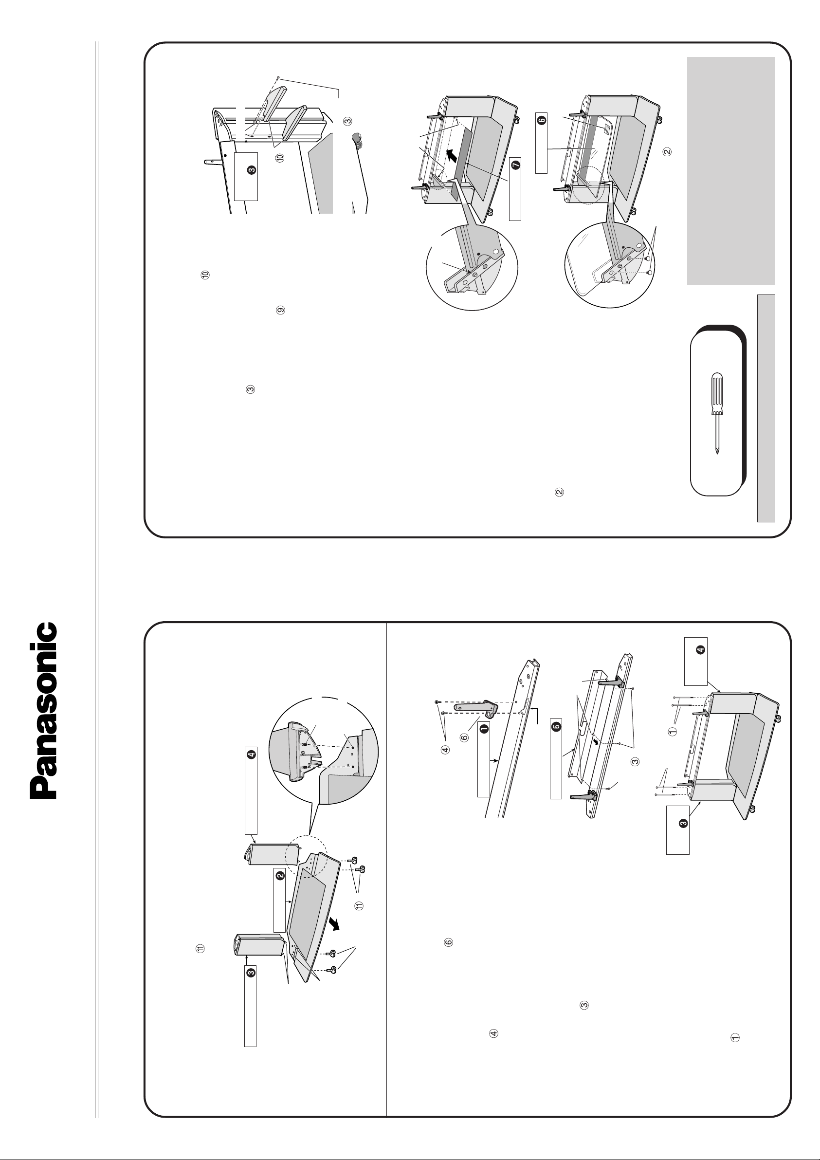
Attaching of glass shelf and cord holder
with the dowel holes in the side panel (left) and insert.
Securely fasten with the glass shelf support fastening
screws (black screws)
1. Align the dowels in the glass shelf supports (left) (× 2)
manner.
2. Attach the glass shelf supports (right)
(left and right), and align the dowels of the cord holder
with the dowel holes in the glass shelf supports. Attach
the other cord holder to the other glass shelf supports in
3. Insert a cord holder in parallel with the glass shelf supports
STEP 3
The tools required:
(× 4). Fit the other glass shelf
glass shelf on the right side,
facing the front. Insert the glass
shelf in parallel with the grooves
in the glass shelf supports (left
and right), and securely fasten
to the bottom of the (left and
right) glass shelf supports using
the same manner.
4. Attach the caution label to one
the glass shelf fastening screws
in the same manner.
Notches
Side panel
(Right)
Plus (Phillips) (+) screwdriver
∗∗
∗∗
∗ Do not use electric powered screwdrivers.
TY-S42PX20U
TY-S50PX20U
Model No.
Dowels
Dowel holes
Side panel (Right)
Bottom panel
Attaching of bottom panel, side panels and casters
Side panel (Left)
Dowels
Front
Casters
Dowel holes
Support pole
Attaching of top crosspiece and rear cord cover
Top crosspiece
fastening screws
Support pole (Right)
(× 2) using a Phillips head (+)
Notches
Rear cord cover
Assembly
screws
Side panel
Rear cord cover fastening
screws (Black screws)
(× 3) into the screw holes on
(Left)
(× 4).
insert.
2. Align the dowels of the side panels (left and right) with the dowel holes in the bottom panel and
1. Securely insert the casters (× 4) into the bottom panel.
Assembly
Assembly & Placement
Manual
STEP 1
on the right side of the top crosspiece, and
securely fasten with the support pole fastening
1. Align the support pole (right) with the notch
STEP 2
screwdriver. Fasten the support pole (left) to
screws
the left side in the same manner.
(black screws)
the back of the top crosspiece and partially
fasten. Slide the 3 notches in the rear cord
2. Insert the rear cord cover fastening screws
cover behind the screws and securely fasten
the screws.
right) with the dowel holes in the top crosspiece
and insert. Securely fasten with assembly
screws
3. Align the dowels of the side panels (left and
 Loading...