

Page 1
Specifications
A
A
A
A
ORDER NO. ITD0608050CE
U/V Tuner Board with Hospitality Port
TY-FB9TE
Receiving Systems /
Band name
OUTPUT
UDIO OUT
VIDEO OUT VIDEO (BNC Type) 1.0 Vp-p (75 W)
Others Ir System terminal × 1
INPUT
UDIO IN
VIDEO IN VIDEO (BNC Type) 1.0 Vp-p (75 W )
ANT-IN UHF / VHF
Mass (Weight) 0.55 kg
PAL B, G, H, SECAM B, G SECAM L / L´
VHF E2 - E12 VHF H1 - H2 (ITALY)
VHF A - H (ITALY) UHF E21 - E69
CATV (S01 - S05) CATV S1 - S10 (M1 - M10)
CATV S11 - S20 (U1 - U10) CATV S21 - S41 (Hyperband)
PAL D, K, SECAM D, K
VHF R1 - R2 VHF R3 - R5
VHF R6 - R12 UHF E21 - E69
PAL 525/60 Playback of NTSC tape from some PAL Video re cord ers (VCR)
M.NTSC Playback from M. NTSC Video recorders (VCR)
NTSC (AV input only) Playback from NTSC Video recorders (VCR)
UDIO L-R (RCA Pin Type × 2) 0.5 Vrms
UDIO L-R (RCA Pin Type × 2) 0.5 Vrms
S-VIDEO (MINI DIN 4-pin) Y:1.0 Vp-p (75 W) C:0.286 Vp-p (75 W)
© 2006 Matsushita Electric Industrial Co., Ltd. All
rights reserved. Unauthorized copying and
distribution is a violation of law.
Page 2

TY-FB9TE
CONTENTS
Page Page
1 Safety Precautions 3
1.1. General Guidelines
1.2. Touch-Current Check
2 Prevention of Electro Static Discharge (ESD) to
Electrostatically Sensitive (ES) Devices
3 About lead free solder (PbF)
4 Installation
5 Antenna connection
6 Connections of external equipment
7 Circuit Board Layout
7.1. HE-Board
8 Block and Schematic Diagram
8.1. Schematic Diagram Notes
8.2. HE-Board Block Diagram
8.3. HE-Board (1 of 8) Schematic Diagram
11
11
12
13
3
3
4
5
6
7
8
9
9
8.4. HE-Board (2 of 8) Schematic Diagram
8.5. HE-Board (3 of 8) Schematic Diagram
8.6. HE-Board (4 of 8) Schematic Diagram
8.7. HE-Board (5 of 8) Schematic Diagram
8.8. HE-Board (6 of 8) Schematic Diagram
8.9. HE-Board (7 of 8) Schematic Diagram
8.10. HE-Board (8 of 8) Schematic Diagram
9 Replacement Parts List
9.1. Replacement Parts List Notes
9.2. Electrical Replacement Parts List
9.3. Mechanical Replacement Parts List
9.4. Parts Location (1)
9.5. Parts Location (2)
10 Sche matic Diagram for printi ng with A4
14
15
16
17
18
19
20
21
21
22
28
29
30
31
2
Page 3

TY-FB9TE
1 Safety Precautions
1.1. General Guidelines
1. When servicing, observe the original lead dress. If a short circuit is found, replace all parts which have been overheated or
damaged by the short circuit.
2. After servicing, see to it that all the protective devices such as insulation barriers, insulation papers shields are properly
installed.
3. After servicing, make the following leakage current checks to prevent the customer from being exposed to shock hazards.
1.2. Touch-Current Check
1. Plug the AC cord directly into the AC outlet. Do not use an isolation transformer for this check.
2. Connect a measuring network for touch currents between each exposed metallic part on the set and a good earth ground such
as a water pipe, as shown in Figure 1.
3. Use Leakage Current Tester (Simpson 228 or equivalent) to measure the potential across the measuring network.
4. Check each exposed metallic part, and measure the voltage at each point.
5. Reserve the AC plug in the AC outlet and repeat each of the above measure.
6. The potential at any point (TOUGH CURRENT) expressed as voltage U
For a. c.: U
For d. c.: U
= 35 V (peak) and U2= 0.35 V (peak);
1
= 1.0 V,
1
Note:
The limit value of U
= 0.35 V (peak) for a. c. and U1= 1.0 V for d. c. correspond to the values 0.7 mA (peak) a. c. and 2.0
2
mA d. c.
The limit value U
= 35 V (peak) for a. c. correspond to the value 70 mA (peak) a. c. for frequencies greater than 100 kHz.
1
7. In case a measurement is out of the limits specified, there is a possibility of a shock hazard, and the equipment should be
repaired and rechecked before it is returned to the customer.
and U2, does not exceed the following values:
1
Figure 1
3
Page 4
TY-FB9TE
2 Prevention of Electro Static Discharge (ESD) to
Electrostatically Sensitive (ES) Devices
Some semiconductor (solid state) devices can be damaged easily by static electricity. Such components commonly are called
Electrostatically Sensitive (ES) Devices. Examples of typical ES devices are integrated circuits and some field-effect transistors and
semiconductor "chip" components. The following techniques should be used to help reduce the incidence of component damage
caused by electro static discharge (ESD).
1. Immediately before handling any semiconductor component or semiconductor-equipped assembly, drain off any ESD on your
body by touching a known earth ground. Alternatively, obtain and wear a commercially available discharging ESD wrist strap,
which should be removed for potential shock reasons prior to applying power to the unit under test.
2. After removing an electrical assembly equipped with ES devices, place the assembly on a conductive surface such as alminum
foil, to prevent electrostatic charge buildup or exposure of the assembly.
3. Use only a grounded-tip soldering iron to solder or unsolder ES devices.
4. Use only an anti-static solder removal device. Some solder removal devices not classified as "anti-static (ESD protected)" can
generate electrical charge sufficient to damage ES devices.
5. Do not use freon-propelled chemicals. These can generate electrical charges sufficient to damage ES devices.
6. Do not remove a replacement ES device from its protective package until immediately before you are ready to install it. (Most
replacement ES devices are packaged with leads electrically shorted together by conductive foam, alminum foil or comparable
conductive material).
7. Immediately before removing the protective material from the leads of a replacement ES device, touch the protective material
to the chassis or circuit assembly into which the device will be installed.
Caution
Be sure no power is applied to the chassis or circuit, and observe all other safety precautions.
8. Minimize bodily motions when handling unpackaged replacement ES devices. (Otherwise hamless motion such asthe brushing
together of your clothes fabric or the lifting of your foot from a carpeted floor can generate static electricity (ESD) sufficient to
damage an ES device).
4
Page 5

TY-FB9TE
3 About lead free solder (PbF)
Note: Lead is listed as (Pb) in the periodic table of elements.
In the information below, Pb will refer to Lead solder, and PbF will refer to Lead Free Solder.
The Lead Free Solder used in our manufacturing process and discussed below is (Sn+Ag+Cu).
That is Tin (Sn), Silver (Ag) and Copper (Cu) although other types are available.
This model uses Pb Free solder in it’s manufacture due to environmental conservation issues. For service and repair work, we’d
suggest the use of Pb free solder as well, although Pb solder may be used.
PCBs manufactured using lead free solder will have the PbF within a leaf Symbol
Caution
·
· Pb free solder has a higher melting point than standard solder. Typically the melting point is 50 ~ 70 °F (30~40°C) higher.
· ·
Please use a high temperature soldering iron and set it to 700 ± 20 °F (370 ± 10 °C).
·
· Pb free solder will tend to splash when heated too high (about 1100 °F or 600 °C).
· ·
If you must use Pb solder, please completely remove all of the Pb free solder on the pins or solder area before applying Pb
solder. If this is not practical, be sure to heat the Pb free solder until it melts, before applying Pb solder.
·
· After applying PbF solder to double layered boards, please check the component side for excess solder which may flow onto
· ·
the opposite side. (see figure below)
Suggested Pb free solder
There are several kinds of Pb free solder available for purchase. This product uses Sn+Ag+Cu (tin, silver, copper) solder.
However, Sn+Cu (tin, copper), Sn+Zn+Bi (tin, zinc, bismuth) solder can also be used.
stamped on the back of PCB.
5
Page 6

TY-FB9TE
4 Installation
6
Page 7
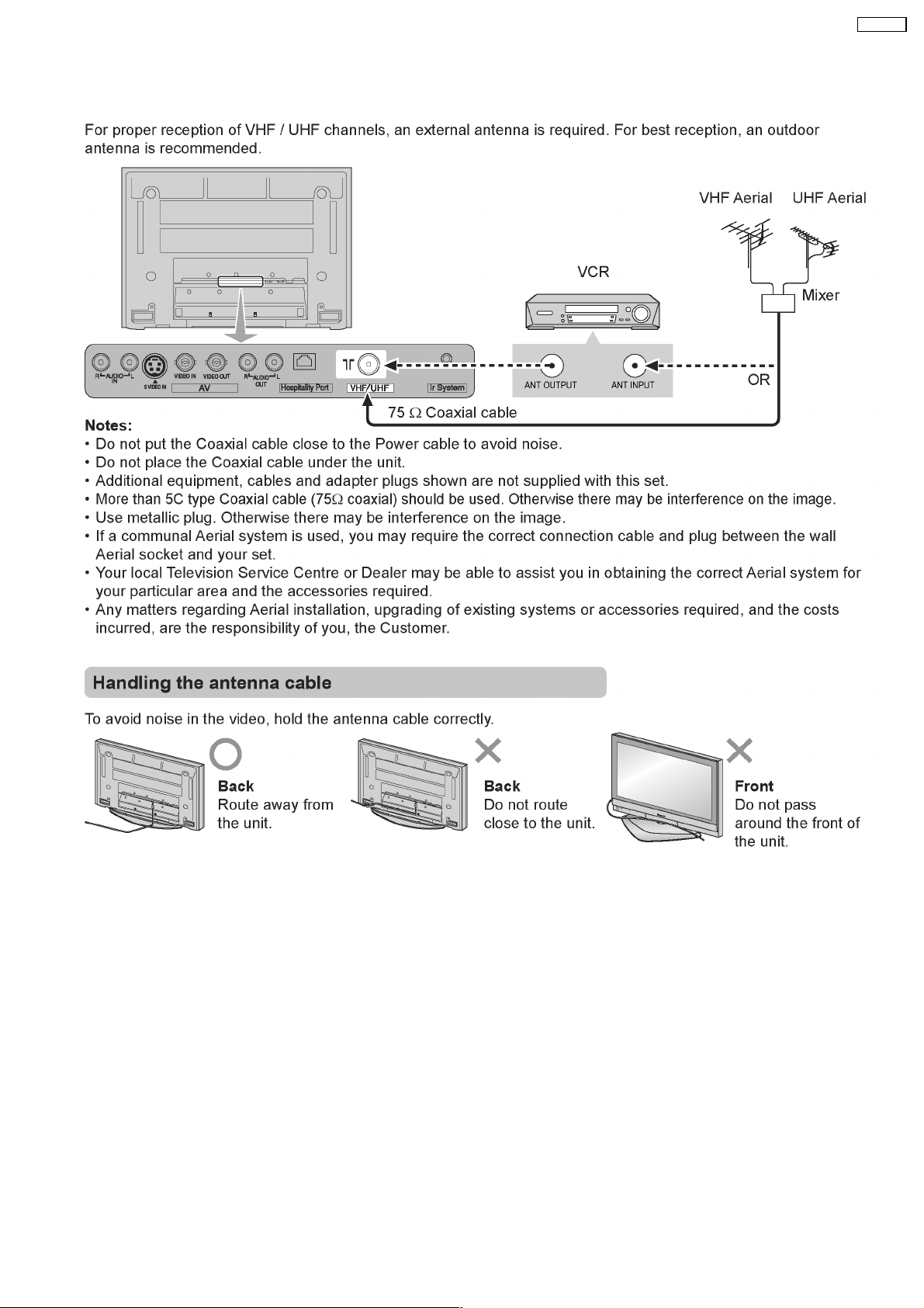
5 Antenna connection
TY-FB9TE
7
Page 8

TY-FB9TE
6 Connections of external equipment
8
Page 9

7 Circuit Board Layout
7.1. HE-Board
6
HE-BOARD (FOIL SIDE)
TXNHE1ZUTE
C525
C666
C662
C663
C664
1
L346
R603
7
TNPA3980
C655
C661
L343
C685
C688
C651
29
C656
C657
3
2
4
31
IC301
30
C481
C484
C487
1
120
8
1
R687
R693
R695
R696
C690
IC328
R682
Q336
JK301
R310
JS317
R520
1
C689
Y
A1
A2
B1
C444
B2
C447
R453
R446
R448
R747
R703
C441
R498
5
90
C490
6
25
C737
C707
1
48
R443
L324
4
91
C437
60
7
R745
R744
C434
3
C668
R437
5
R429
C704
C703
L
56
C699
C698
5
C455
R462
ZA305
R459
Q323
8
R470
C450
R748
Q320
C463
R750
24
IC324
13
4
12
1
61
14
3
IC322
1
4
R754
IC325
C728
C723
1
C729
C724
ZA307
R755
R712
8
7
C731
C726
3
8
5
6
C720
C721
R752
2
JK302
R
1
28
24
C669
5
R519
R758
R757
IC318
R509
R753
1
R485
R493
TY-FB9TE
Parts Location
HE-BOARD
ORDER
B39
10
C456
C438
C431
C402
B40
3
R576
1
5
C597
3
L342
1
R612
R620
R614
C622
R700
R506
JS307
R530
C551
C559
C621
R681
C478
R613
C619
C618
C617
R624
C616
C611
NO.
C512
C511
C601
C543
C542
IC310
R475
R615
C498
C477
R621
C620
C516
R505
C480
R471
C476
C567
C514
C513
R622
C614
C612
R481
C615
R473
C472
C470
R634
R627
C613
C568
R578
C602
C474
C475
2
R479
R502
R501
R480
R472
C479
R633
C519
C493
R562
C598
C603
C541
L332
5
R503
C473
R
C566
R580
R587
C489
IC313
L328
R561
C496
C595
C468
C676
C565
R579
L339
C492
C495
C604
C600
C594
C626
R680
JS308
C491
R500
C465
C466
R678
L337
Q324
R504
C494
R465
JK304
C608
R586
C605
R581
C488
IC308
R582
JS313
L336
C607
Q325
R584
R499
C458
R685
C599
D313
Q326
R577
C460
R676
JS306
JS314
R684
L340
R585
C673
R625
C529
D312
R611
C534
R679
R599
C553
R598
R595
R420
C558
C557
C531
C550
C554
C518
C545
C546
C549
R727
R675
C535
L
C719
C718
R477
R478
8
R544
R551
R726
R740
R739
CR NO.3
R671
R672
R674
R673
R543
R558
5
8
IC307
R440
R439
R438
C429
R626
C427
C428
L319
R449
R410
R408
4
C552
C537
C544
C548
C556
C536
JS312
C515
C517
D311
R463
R402
R516R517
4
R424
R431
C672
5
1
13
R430
8
PbF
C752
R349
L304
JS309
C580
C581
C539
C509
C508
FL306
C304
R300
VIDEOOUT
SIFOUT
AUDIOOUT
C305
RFAGC
C502
IC312
C579
C528
C743
R759
L331
C578
BTL
AFT
SDA
SCL
R527
R604
R761
BT
C505
R528
C753
IC331
R769
Q331
R771
C760
Q311
R372
FL310
R382
JS305
JS304
Q330
R770
C776
R772
R377
C362
R373
C670
D310
R768
5
IC311
R608
C561
C562
C563
R605
C624
R762
C744
R760
1
D301
R312
R311
R557
R547
C564
5
D308
Q335
R552
R554
C582
R490
FL301
R556
R545
JS310
C586
C589
C301
R555
R549
C584
R375
R483
R560
C575
Q302
L301
L300
R569
C583
C573
R376
FL300
R550
C560
C591
C555
IC330
C328
R379
C360
C361
R381
R484
C442
C443
R486
R602
R575
R568
C585
L334
C510
C572
C302
C574
C577
R482
C576
C547
8
Q313
L354
Q314
Q332
Q333
R489
Q334
R374
Q312
R371
R383
FL309
C346
C347
C338
R366
R328
Q309
C343
R363
R361
TU300
R553
R559
R532
R546
R548
JS311
R507
1
C533
C530
C532
R510
C764
IC333
X301
1
1
4
C773
C766
5
8
L356
4
1
JS301
C356
C331
R370
Q310
Q308
R339
Q304
R333
C501
IC340
R491
3
IC319
5
8
C426
4
R428
JK305
2
7
C774
C401
IC303
C321
R743
R365
Q305
R515
C771
C404
C357
C350
R367
C342
C341
L307
R358
R355
R332
C767
R765
C757
R394
C386
R395
C340
R357
R356
R742
C713
R764
C387
R398
C389
R389
R387
R409
Q303
R329
R433
R466
C358
R341
R330
1
C770
JS300
R474
C482
C483
R724
C709
Q329
C754
C772
R766
R767
IC334
C485
C486
C497
C756
R763
R401
C388
R388
R386
D307
C359
R406
R492
4
4
D309
C397
58
C761
C430
R378
R345
R677
R512
R511
TP305
1
C759
C399
Q317
C327
ZA304
C330
C504
R346
C325
Q307
R347
R348
C323
X305
R334
Q340
ZA306
R335
C320
C593
IC329
R589
R524
C677
R342
C324
R600
R344
R583
R343
R590
Q306
Q341
C678
1
5
C507
C527
C326
C329
R350
X304
BM
JK303
1
HE
A39
A40
H1
C667
R657
1
TP307
VD
HD
TP306
R609
TP304
C716
R522
C717
R749
5
IC337
4
C523
1
7
C524
1
7
IC326
C727
L353
C722
C
R637
R641
R638
C636
C635
R644
R513
R645
Q339
C526
R315
R494
R647
R588
R497
C642
R653
R456
R455
R454
R434
C499
Q338
R652
R523
R495
JS315
C633
C637
C641
C640
C639
R646
C638
R636
JK300
R746
R686
R496
JS316
R514
X303
C522
14
IC336
8
14
R467
8
C634
VIDEO IN MONITOR OUT
11
R521
R606
R650
R426
R591
4
4
C596
C606
4
1
5
R403
IC338
20
R529
ICIC
IC3301 B-4
IC3303 F-2
IC3307 E-4
IC3308 D-2
IC3310 D-2
IC3311 F-2
IC3312 G-1
IC3313 D-2
IC3318 B-5
IC3319 E-5
IC3322 A-3
IC3324 A-4
IC3325 A-2
IC3326 C-2
IC3328 B-2
IC3329 H-5
IC3330 G-5
IC3331 F-4
IC3333 E-4
IC3334 F-3
IC3336 C-2
IC3337 B-3
IC3338 C-2
IC3340 F-1
TRANSISTOR
Q3302 G-3
Q3303 F-2
Q3304 F-2
Q3305 F-2
Q3306 H-3
Q3307 H-3
Q3308 F-2
Q3309 G-3
Q3310 F-2
Q3311 F-3
Q3312 G-3
Q3313 G-4
Q3314 G-4
Q3317 F-2
Q3320 A-5
Q3323 A-4
Q3324 D-4
Q3325 D-4
Q3326 D-2
Q3329 F-1
Q3330 F-4
Q3331 F-4
Q3332 G-4
Q3333 G-4
Q3334 G-3
Q3335 G-3
Q3336 B-2
Q3338 C-3
Q3339 C-1
Q3340 H-3
Q3341 H-3
TP
TP3304 C-4
TP3305 F-1
TP3306 C-4
TP3307 C-4
TY-FB9TE
HE-BOARD TXNHE1ZUTE
ABCDEFGH I
TY-FB9TE
HE-BOARD TXNHE1ZUTE
9
Page 10

TY-FB9TE
6
HE-BOARD (COMPONENT SIDE)
TXNHE1ZUTE
C
C659
C588
R571
ZA300
R573
C587
R574
5
PbF
IC341
C742
L305
L306
BTL
AUDIOOUT
X304
SDA
SCL
C503
C337
49
64
R359
VIDEOOUT
AFT SIFOUT
RFAGC
BT
C339
48
1
IC335
HE
1
FOR
NO.
4
3
ORDER
REVERSE
TNPA3980
SEE
C334
C335
X300
C332
C333
C345
FL307
R353
R304
R309
R601
R314
C313
C314
CR NO.3
X305
AGC
R308
Q300
TP300
ZA301
2
R331
JK303
BM
1
C590 R570
R360
R572
C571
R567
C569
5
1
R564
R566
C609
R563
C570
4
C344
R565
R540
C610
3
R340
R542
R656
C348
33
16
R669
R541
C745
C592
C351
32
TU300
R536
R670
C658
C538
17
C679
R692
R698
C471
C749
C762
C353
L329
C739
FL311
Q327
R655
R697
D305
C354
C520
R487
C652 R701
C352
C355
R705C653
C654 R709
C747
D303 D304
C692
FL312
D306
R710
C740
L348
C694
5
IC332
R706
C695
C758
C368
R441
L322
R435
R425
C435 C439
C432
R427
R436
C433 L323
C746
1
3
C763
L311
C521
R488
R450
R444
R442
R445
R447
C436
C440
C741
FL313 FL314
C738
4
C765
C755
C364
R623
C349
R368
R369
Q318
Q319
C540
C768
C674
R451
C448
R469
R452
C449
R468
IC304
C367
C369
C363
C748
5
1
L315
C392
C393
C374
R384
R397
L313 C370
D
C500
R508
C459
IC309
R464
4
3
A
C378
C381
C384
C385
C390
R396
C375
R385
C391
C371
R390
C379
C380
R391
R392
C382
R393
C383
L310
C373
A
C376
C394
L317
R380
C365
C372
L314
C377
Parts Location
HE-BOARD
ICIC
IC3300 E-3
IC3302 D-2
IC3304 C-4
IC3305 D-4
IC3306 D-3
IC3309 C-5
IC3315 E-3
IC3317 F-2
IC3320 E-5
IC3321 G-3
IC3323 F-3
IC3327 H-2
IC3332 B-4
IC3335 A-4
IC3341 A-5
TRANSISTOR
Q3300 A-3
Q3301 D-1
Q3315 F-2
Q3318 C-5
Q3319 C-5
Q3321 H-5
Q3322 H-5
Q3327 B-5
Q3328 G-2
TP
TP3300 A-2
TP3301 E-5
TP3302 E-5
TP3303 E-5
TP3308 D-5
TP3309 D-5
TP3310 D-5
TP3311 D-5
TP3312 D-5
TP3313 D-5
TP3314 D-5
TP3315 D-5
TP3316 D-5
TP301
TP302RTP303
C408
C409
C405
C395
L316
C407
C366
C457
R476
C464
36
37
72
73
JS303
R325
R327
C322
NP
C317
R399
C318
2
JK305
R400
1
R665
R660
R666
R661
C316
C319
R405
JS302
25
R404
TP308
R407
C398
C396
TP309
R411
36
37
H4
D
C420
24
7
C403
TP310
8
C406
C410
1
1
TP313
TP311
TP312
R414
C411
TP314
R418
R415
C413
1
IC305
109
108
3
1
5
4
13
48
NP
C307
R323
C315
R322
R317
C419
R316
R313
Q301
144
C412
C422
C423
12
7
TP315
C414
C417
C415
C416
C418
R421
R422
R412
R413
C421
1
R416
R417
R419
IC306
IC302
C627
C625
L
H3
8
TP316
C424
C631
C632
C630
C629
C308
R592
R423
C425
R593
R432
C628
JK304
R597
C671
R630
R628
R629
R596
R663
R525
R526
R531
R534
R632
44
86
FL315
R662
R664
R594
B
9
16
A
B
C
D
EF
G
HJ
K
LM
N
P
R
TU
V
W
Y
AA
AB
AC
ADAE
AF
R631
R668
R667
G
8
1
IC320
123456789
R618
FL316
R610
R
A39
A40
R658R659
C506
101112
IC300
R619
R616
R617
IC315
C733
C735
C734
C736
C623
143
B
R688
R689
R690
R607
R691
R338
R337
C644
13
R651
C649
C650
C647
C648
C646
C645
C643
JK300
B39
R305
B40
141516
R654
171819
86
C303
D300
44
R321
H1
FL308
R307
20
R319
R649
C309
21
C311
FL302
22
R648
R643
R301
23
R320
C
24
NP
R303
C310
25
FL303
R302
26
R538
R537
R539
R642
R318
R533
R535
43
FL305
C687
C693
IC323
C680
R741
C681
C682
C714
C400
Q315
1
C660
C665
3
R694
C696
4
R518
IC317
R324
C306
C700
R639
R640
C312
C467
C701
FL304
C715
B
5
R635
C683
C684
R683
R336
1
R699
R306
C
R702
32
IC321
NP
128
Q328
L361
C469
C697
C686
C691
1
33
C732
R707
27
28
Y
JK301
R713
X302
A1
A2
B1
B2
C706
L350
R715
R717
97
1
IC327
54
L
R
ZA302
C453
Q321
C454
Q322
C461
C445
C462
C452
R457
R460
C446
C451
R458
R461
R735
L351
R721
R730
R729
R736
R731
96
65
64
R711
C710
C711
R714
L352
C730
C725
ZA303
R737
C708
R722
D302
R738
C712
R728
R732
R733
R734
R716
R725
JK302
TY-FB9TE
HE-BOARD TXNHE1ZUTE
ABCDEFGH I
TY-FB9TE
HE-BOARD TXNHE1ZUTE
10
Page 11

8 Block and Schematic Diagram
8.1. Schematic Diagram Notes
TY-FB9TE
11
Page 12

TY-FB9TE
8.2. HE-Board Block Diagram
BTL
AFT
SCL
SDA
SIF OUT
RF AGC
CY
1
2
3
4
5
6
7
5V_SDA_2
8
5V_SCL_2
Q3315
BT30V
TUNER
15
BM
3
12
10
11
13
17
14
8
1
2
5V
Q3302
5V_SCL1
5V_SDA1
TP3306
RF-AGC
1-NC
1-H
1-G
2-NC
2-H
2-G
L
L-G
R
R-G
L
L-G
R
R-G
IC3303
PLL 2.5V
MAIN_3.3V
1
5
IC3308
AD 3.3V
MAIN_5V
1
5
1:Rx
2:Tx
3:nc
4:GND
5:GND
6:Remote
7:SDA
8:SCL
JK3305
HOSPITALITY PORT
JK3303
IR OUT
TU3300
TUNER
AUDIO OUT
VIDEO OUT
JK3301
VIDEO IN(C,Y)
JK3300
MONITOR OUT(V)
VIDEO IN(V)
JK3302
AUDIO IN(L,R)
JK3304
MONITOR OUT(L,R)
HE
INV. INV.
Q3328
Q3340,
Q3341
Q3306,
Q3307
2.5V
PLL
4
OSD
3.3V
4
TUNER,AV IN/OUT,
IR OUT,HOSPITALITY PORT
Q3336
IC3336
CLOCK
X3303
1
STB5V
4
14
VCC
IC3302
MON-V
VIDEO SW
34
47
5
3
1
7
14
Q3301
Q3300
MAIN+9V
AV-S-DET
AV-S-DET
TV
AV-C
AV-Y
AV-V
IC3335
AUDIO SW & MSP
SC1_IN_L
41
SC1_IN_R
42
I,D/K:Lo
60 D_CTR_I/O
L,B/G:Hi
SIF
AV-L
AV-R
MON-L
MON-R
Q3332
Q3333
DEMOD
50
ADC
44
ADC
45
26
25
MUTE
D3310
IC3304
AD 2.5V
MAIN_3.3V
1
4
5
IC3312
DDIF/OUT PLL 3.3V
MAIN_5V
4
1
5
INV.
LOGIC
2.5V
AD
RXD_MAGI
TXD_MAGI
2
3
6dB
6dB
6dB
6dB
DAC
DAC
SOUND SELECT
3.3V
PLL
REMOTE
MAIN_9V
OUTPUT SELECT
D3309
MAIN_3.3V
MAIN_3.3V
IC3329
IC3330
Y
43
C
45
V
40
36
27
26
33
29
28
SDA
2
SCL
1
Q3334
Q3335
IC3306
MAIN 2.5V
1
5
IC3313
SDRAM PLL 1.8V
1
5
TUNER 5V
1
2
MSP 8V
1
2
SDA1
SCL1
L
R
MSP+8V
4
4
SDA1
SCL1
D3308
3
6
3
6
Q3314
Q3313
TUNER+5V
TUNER+5V
MSP+8V
MSP8V
MAIN
2.5V
1.8V
PLL
STB_5V
MUTE
IC3331
STB 2.5V
1
2
IC3332
STB 3.3V
1
5
3
4
STB+2.5V
STB+3.3V
MAIN
3.3V
MAIN_3.3V
MAIN+9V
Q3303
OSD_B
OSD_G
OSD_R
Q3305
Q3304
IC3333
MAIN 1.8V
6
IC3334
U/V TUNER 30V
3
4
IC3323
STB+3.3V
3.3V
OSD
X3301
20.25MHZ
5
1
8 VCC
5
5
Q3331
Q3327
RESET
RST
2
Q3318,Q3321
Q3319,Q3322
Q3320,Q3323
MAIN
3.3V
3
20.25MHZ
7
IC3307
Q3310,Q3311
Q3309,Q3312
MAIN+3.3V
1
CLOCK
MAIN
1.8V
BT30V
SDA0
SCL0
D3302
LED G
D3306
Q3330
X3302
Q3326
HS
VS
OSD_R
OSD_G
OSD_B
HS
VS
SDA0
SCL0
2.5V_AD
IC3321
G
LED
80
R
108
XTAL1
109
XTAL2
5
REMOTE IN
125
AFC
90
MUTE
97
LCD MUTE
103
HSYNC
102
VSYNC
121
CVBS1
112
OSD R
113
OSD G
114
OSD B
73
RESET IN
78
GC3 RST
IC3301
OSD RGB A/D
FORMAT CONVERTER
58
NRST
110
YIN
PBIN
41
PRIN
44
54
55
67
CKXI
71
HSIN
65
VSIN
27
PROUT3
23
PROUT7
18
PBOUT2
13
PBOUT7
7
YOUT3
SDA
SCL
YOUT7
CLK IN
YSOUT7
YSOUT6
YSOUT5
YSOUT4
IC3305
33
NRST
24
FRCLKIN
56
VIN3
42
VIN1
26
SDA
25
SCL
3
70
93
94
95
96
GC3FM
MICOM
ALFA3
ALFA2
ALFA1
ALFA0
YUVO0
YUVO9
MDO10
MDIN0
MDIN15
TXD MAGINET
RXD MAGINET
MDO0
UART_SEL
TXDO
RXDO
SCL2
SDA2
SCL1
SDA1
SCL0
SDA0
EEPROM-WP
20
8
5
3
143
136
132
115
IC3327
64M SDRAM
IC3328
16M FLASH
81
IC3340
STB3.3V
14
1183
Q3329
PORT B
OSDIN0
OSDIN15
HSOD
VSOD
CLKOD
OSDYS
OSDYM
YINC1
YINC0
PORT C
NRST
FRCLKIN
PORT B
SDA
SCL
PORT A
YUVINA0
YUVINA9
MDINA0
MDINA10
MDOA0
MDOA15
4
8
12
9
SRQ
94
88
89
100
101
98
99
74
75
76
HS
VS
SDA0
SCL0
SW
VCC
STB+3.3V
IC3300
STB+3.3V
STB+3.3V
12
10
5
3
13
9
6
8 VCC
5
SDA
IC3322
6
SCL
7
SDRAM A
SDRAM B
GC3I
EEPROM
WP
MAIN
1.8V
1.8V_PLL
MAIN_3.3V
3.3V_PLL
PORT E
R0E2-9
G0E2-9
B0E2-9
HD
TP3306
HSOE
VSOE
CLKE TxCLKIN
LCD MUTE
TP3307
Q3317
VD
INV.
SCL0
SDA0
STB+5V
IC3315
64M SDRAM
IC3317
64M SDRAM
50
51
56
2
3
4
14
15
16
18
24
27
28
31
IC3338
RS232C DRIVER
13
15
20
SHUTDOWN
1
VCC
EN
IC3324
3.3V->5V
24
VCC
11
B10
A10
9
A8
B8
8
B7
A7
7
B6
A6
6
A5
B5
5
B4
A4
4
A3
B3
3
A2
B2
2
A1
B1
IC3319
EEPROM
(CARD DATA)
MAIN
3.3V
MAIN
3.3V
IC3320
6
10
IC3318
LVDS TRANSMITTER
TxIN27
TxIN0
TxIN4
TxIN5
TxIN6
TxIN7
TxIN14
TxIN15
TxIN16
TxIN17
TxIN22
TxIN24
TxIN25
TxOUT0-
TxOUT0+
TxOUT1-
TxOUT1+
TxOUT2-
TxOUT2+
TxOUT3-
TxOUT3+
TxCLKOUT-
TxCLKOUT+
17
16
19
13
15
16
17
18
19
20
21
22
Ex.I/O
P2
P5
PWRDWN
R_FB
STB+3.3V
SDA
SCL
WP
SCL
SDA
32
17
48
47
46
45
42
41
38
37
40
39
5V_SCL2
5V_SDA2
5V_SCL1
5V_SDA1
5V_SCL0
5V_SDA0
8VCC
5
6
7
14
15
MAIN+3.3V
TXD_MAGI
RXD_MAGI
STB+5V
STB+5V
REMOTE
Q3317
MAIN+3.3V
STB+5V
MAIN+9V
MAIN+5V
5V_SCL1
5V_SDA1
5V_SCL0
5V_SDA0
STB+5V
5V_SCL2
5V_SDA2
FOR
FACTORY
H3
USE
SRQ
2
SCL1
4
SDA1
5
SCL0
6
SDA0
7
STB5V
1
FOR
FACTORY
H4
USE
STB5V
1
SRQ
8
SCL2
4
SDA2
5
SCL_PANEL
6
SDA_PANEL
7
SRQ_PANEL
2
H1
TO PDP SLOT
B23
SRQ_PANEL
B26
TXD
B27
RXD
B24
SDA_PANEL
B25
SCL_PANEL
B30
REMOTE
A22
5V_STB
A21
9V_MAIN
B21
9V_MAIN
A19
5V_MAIN
B19
5V_MAIN
A17
3.3V_MAIN
B17
3.3V_MAIN
B2
RX0-
B3
RX0+
B5
RX1-
B6
RX1+
B8
RX2-
B9
RX2+
B14
RX3-
B15
RX3+
B11
RXCLK-
B12
RXCLK+
A26
LOUT
A28
ROUT
TY-FB9TE
HE-Board Blcok Diagram
TY-FB9TE
HE-Board Block Diagram
12
Page 13

8.3. HE-Board (1 of 8) Schematic Diagram
TY-FB9TE
TUNER5V
RF_AGC
AUDIO_OUT
SIF_OUT
VIDEO_OUT
D3300
MAZ31000ML
!
TU3300
ENG37A26GF
BM
TUNER
3
NC
4
NC
5
NC
6
BT
7
8
NC
9
SCL
10
SDA
11
AFT
12
13
14
BTL
15
NC
16
17
R3301
180k
R3302
180k
R3303
75
1%
R3304
J0HABB000004
C3303
25V
0.1u
R3306
C3304
50V
56p
C3305
50V
56p
0
FL3307
R3308
220
75
R3307
FL3302
J0HABB000004
123
123
FL3303
J0HABB000004
J0HABB000003
123
1%
75
J0HABB000004
123
L3300
EXC3BB102H
L3301
EXC3BB102H
123
123
4
4
FL3304
4
123
1%
FL3305
R3311
100
R3312
100
FL3306
J0HABB000004
4
4
R3314
560
R3601
560
C3309
1u
16V
C3310
16V
C3306
0.1u
25V
FL3308
J0HABB000004
4
R3310
100
NP
C3311
4
10u
10V
IC3302
C1AB00000461
1u
C3313
Q3300
2SB0709A0L
NP
C3312
10u
10V
16V
1u
R3319
1k
R3320
1k
R3318
220
R3321
220
A
C3503
10u
16V
FL3301
ELKE103FA
TP3300
+
123
C3301
0.1u
16V
R3300
0
B
BT30V
FL3300
ELKE103FA
123
C3302
0.01u
50V
JK3302
K2HA204B0097
AUDIO IN
L
L_IN
L-G
R
R_IN
R-G
C
JK3301
K1CB106B0027
S-VIDEO IN
D
JK3300
K1QBB2AB0005
VIDEO OUT
VIDEO IN
CY
1
2
1-NC
1-H
1-G
2-NC
2-H
2-G
AV SW
FL3315
R3315
1k
JK3304
K2HA204B0097
AUDIO OUT
L
L-G
R
R-G
E
JK3305
K2LC108B0063
HOSPITALITY PORT
F
JK3303
K2HC103B0105
IR OUT
1:Rx
2:Tx
3:nc
4:GND
5:GND
6:Remote
7:SDA
8:SCL
1
2
3
R3428
0
4
5
R3402
6
R3463
7
R3465
8
J0HABB000003
123
4
123
4
FL3316
J0HABB000003
AJ_RXD_MAGI
AJ_TXD_MAGI
100
AI_SDA_2
68
AI_SCL_2
68
R3305
R_MON_OUT
L_MON_OUT
C3307
Q3301
16V
2SD0601A0L
0.1u
75
1%
C3308
470u
16V
R3317
+
100
R3313
R3316
470
470
R3602
100k
C3314
50V
0.1u
R3324
220
10Y211
12
RV2
13
S-2
14
V3
C2
15
S2-2
LV3
16
Y3
17
RV3
18
C3
19
S2-3
20
RV425ADR
S-3
21
LV4
22
V4
23
24
SCL27SDA28DC OUT29COUT230LOUT231YOUT232ROUT233VOUT234Vcc35MUTE
26
22
R3325
R3327
AI_SCL_1
AI_SDA_1
R3322
10k
NP
C3315
R3323
10V
15k
10u
AI_SCL_1
LV2
22
AI_SDA_1
R3328
4.7k
AFC
Q3302
2SB0709A0L
1V12
3Y14
5C16
7
8V29
LV1
RV1
S-1
S2-1
TV
LTV
COUT1
GND
RTV
YOUT1
TRAP1
ROUT1
BIAS
VOUT1
YIN1
LOUT1
CIN1
36
C3316
0.1u
16V
STB5V
Q3315
2SB0709A0L
R3331
39
TY-FB9TE
AS_AFC
C3507
16V
AC_AV_L
AC_AV_R
1u
C3527
16V
10u
16V
41
43
44
46
ASG
VREFTOP
SC1_IN_L45SC1_IN_R
MONO_IN
AVSS
AVSUP
ANA_IN-
ANA_IN1+
ADR_SEL63STANDBYQ64NC
l2C_CL
l2C_DA
l2S_CL
l2S_WS5l2S_DA_OUT6l2S_DA_IN17ADR_DA8ADR_WS9ADR_CL10DVSUP11DVSS12l2S_DA_IN213NC
3
4
C3344
0.1u
R3360
100
1u
SC4_IN_L
SC2_IN_L42SC2_IN_R
50V
40
RESETQ
AS_REMOTE
ASG
AGNDC
AHVSS
+
+
C3348
3.3u
50V
34
35
36
37
38
ASG
SC4_IN_R
SC3_IN_L39SC3_IN_R
SC1_OUT_L
SC1_OUT_R
VREF1
SC2_OUT_L
CAPL_A31AHVSUP32CAPL_M
SC2_OUT_R
NC
DACM_SUB
NC
DACA_R18DACA_L19VREF2
DACM_L
DACM_R
NC
15NC16
14
R3368
12k
R3369
C3345
15k
6.3V
100u
L3305
G1C330K00017
C3334
50V
0.1u
C3329
C3326
56p
50V
47p
50V
C3327
R3349
50V
470
10p
C3328
50V
22p
L3304
AS_AFC
D3301
MA3X152K0L
R3334
10k
C3320
0.1u
R3342
16V
3.3k
R3524
C3593
0.1u
330
16V
Q3304
2SD0601A0L
R3333
150
R3339
330
Q3305
100
Q3328
2SD0601A0L
2SD0601A0L
R3332
150
C3321
16V
R3330
0.1u
1k
C3322
16V
Q3303
2SB0709A0L
R3519
4.7k
Q3336
2SD0601A0L
48
47
46
45
44
43
42
41
40
C3319
39
1u
16V
38
37
+
C3318
47u
C3317
16V
1u
16V
C3400
16V
0.1u
R3329
R3518
10k
R3336
1k
R3343
3.3k
Q3306
2SD0601A0L
X3304
EFCT7004BF
X3305
EFCT6504BF
R3341
330
NP
10u
AA_CVBS1
H0J367200001
C3523
R3520
22k
Q3340
2SD0601A0L
X3303
22p
50V
R3346
470
Q3341
R3600
680
2SD0601A0L
R3344
560
R3583
1k
C3677
50V
0.1u
C3522
R3513
50V
470k
22p
R3509
4.7k
ELJFA6R8MFB
C3325
C3678
50V
0.1u
Q3307
2SD0601A0L
50V
0.1u
R3348
560
R3590
1k
CLOCK GEN.
IC3336
C0JBAB000472
1
2
3
4
5
9.1M
R3514
6
78
R3353
4.7k
R3350
100
14
13
12
11
10
9
C3335
50V
47p
H0J184500027
L3306
G1C330K00017
STB5V
C3524
16V
0.1u
+
C3337
16V
0.1u
C3339
47
48
49
50
51
52
ANA_IN2+
53
TESTEN
54
XTAL_IN
55
XTAL_OUT
56
TP
X3300
57
AUD_CL_OUT
58
NC
59
NC
60
D_CTR_I/O_1
61
D_CTR_I/O_0
62
1
2
R3359
100
AI_SCL_1
AI_SDA_1
5V
JS3316
C3351
16V
0.1u
33
30
29
28
27
26
25
24
23
22
21
20
17
C3349
1u
6.3V
C3352
50V
0.1u
C3353
+
10u
16V
C3354
+
10u
16V
IC3335
C1AB00001942
MSP
MSQ_RST
MSP8V
C3360
10V
R3375
1u
100
R3376
C3361
100
10V
R3379
1u
C3442
R3482
100
R3483
C3443
100
10V
!
R3381
100k
100k
Q3313
10V
1u
1u
UNR521100L
R3484
R3486
180k
180k
Q3332
UNR521100L
Q3314
UNR521100L
Q3333
UNR521100L
HE-BOARD TXNHE1ZUTE (1/8)
HE-Board (1 of 8) Schematic Diagram
L_OUT
R_OUT
AS_MUTE
D3309
MA3X152E0L
Q3335
2SB0709A0L
MSP8V
R3488
180k
+
C3521
16V
22u
R3490
10k
L_MON_OUT
R_MON_OUT
D3310
MA3X152E0L
Q3334
2SB0709A0L
D3308
MA3X157A0L
R3487
1M
+
C3520
16V
47u
R3489
10k
TY-FB9TE
HE-Board (1 of 8) Schematic Diagram
1
2
3
4
5
5 914
13
6
72
83
Page 14

TY-FB9TE
8.4. HE-Board (2 of 8) Schematic Diagram
1
!
HE-BOARD TXNHE1ZUTE (2/8)
C3338
16V
0.1u
R3361
2
470
R3363
560
R3366
820
1%
C3343
50V
Q3309
22p
1%
2SB0709A0L
3
C3331
16V
0.1u
4
R3356
0
C3341
50V
R3358
18p
287
L3307
1%
G1C6R8K00005
C3340
C3342
50V
56p
150p
R3370
680
Q3310
2SB0709A0L
R3365
1%
510
50V
1%
1.33k
R3367
5
TY-FB9TE
HE-Board (2 of 8) Schematic Diagram
11
12
AB_FM_TDO
J0JHC0000078
R3380
JS3303
JS3304
JS3305
MAIN9V
L3311
C3368
16V
0.1u
IC3304
C0CBCAD00012
MAIN3.3V
C3367
16V
0.1u
R3382
0
0
G1C100KA0009
1
Vcont
Vin4Vout
5
R3383
0
C3370
L3313
C3371
50V
0.01u
2
3
Np
AD2.5V
GND
J0JCC0000241
C3369
6.3V
1u
C3372
+
47u
4V
16V
1%
R3385
C3375
470
16V
50V
68p
R3384
0
R3387
L3314
C3373
0.01u
C3382
C3386
0.1u
0.1u
1.4k
MAIN3.3V
16V
50V
C3380
16V
16V
0.1u
16V
R3392
16V
16V
16V
16V
50V
R3386
1.4k
1%
1%
J0JHC0000078
C3377
16V
36
0.1u
C3378
C3379
C3384
C3385
R3394
R3395
C3387
37
0.1u
16V
0.1u
R3391
33
0.1u
C3381
0.1u
33
R3393
33
C3383
0.1u
0.1u
0.1u
33
33
0.1u
C3390
1000p
R3388
R3389
1k
C3376
16V
0.1u
L3315
AVDAD11
40
R3390
VRH1
41
1%
33
VIN1
42
R3399
1%
VRL1
43
1%
150
AVSAD22
44
AVDAD22
45
AVSAD21
46
AVDAD21
47
VRH2
1%
48
R3400
VIN2
49
150
1%
VRL2
50
1%
AVSAD32
51
AVDAD32
52
AVSAD31
53
AVDAD31
54
VRH3
1%
55
R3401
VIN3
56
150
1%
VRL3
57
1%
AVDCLP
58
AVSCLP
59
UCLP
60
VCLP
61
R3396
YCLP
62
2.7k
1%
VRO1
63
1k
VREF1
1%
64
C3388
AVSDA1
65
1u
6.3V
AVDDA1
66
R3398
AOUT1
67
2.7k
VRO2
1%
68
1%
VREF2
69
C3389
70
6.3V
1u
73
R3397
1%
470
C3392
16V
C3393
0.1u
C3391
16V
L3316
0.1u
J0JCC0000241
C3363
16V
0.1u
+
C3362
C3346
Q3312
6.3V
2SD0601A0L
1u
33
R3374
470
Q3311
2SD10300TL
R3373
330
IC3303
C0CBCAD00012
1
2
Vcont
GND
Vin4Vout
5
C3358
6.3V
1u
PLL2.5V
R3377
C3359
16V
1u
R3378
0
C3357
50V
0.01u
3
Np
R3371
C3347
6.3V
1u
C3350
6.3V
R3372
10u
33
MAIN3.3V
C3356
6.3V
1u
JS3300
JS3301
JS3302
C3364
16V
16V
47u
1u
0
C3365
50V
68p
L3310
G1C100KA0009
JTAG_TMS
JTAG_TDI
R3411
SDA_0
SCL_0
EXB38V560JV
22
22
R3408
R3410
0
0
100
R3404
R3405
R3407
0.1u
0.1u
0.1u
C3396
34
35
C3403
C3398
16V
16V
16V
22
23
24
25
30
31
32
VSS
VDDI
VDDE33NRST
EXVPIN
EXHPIN
TDO
AVSAD1238AVDAD1239AVSAD11
VSS
SCL26SDA27VPD28TMS29TDI
VDDE
FRCLKIN
20.25MHz
R3414
EXB38V560JV
56
56
YUVO3
YUVO2
YUVO1
YUVO5
YUVO4
YUVO6
YUVO0
16V
16V
0.1u
C3410
C3406
21
VDDI
IC3305
C1AB00002165
GC3FM_s
AVSDA271AVDDA272AOUT2
VDDE
BXSDDIF
VDDI
DDIF35877VSS78AVSPL179AVDPL180CPO181VGS182VGS283CPO284AVDPL285AVSPL286VSS87FRNT35888VDDI89BXSFRNT90VDDE91VSS92TEST93TRST94TCK95HADIN996HADIN897HADIN798HADIN699HADIN5
74
75
76
C3394
0.1u
16V
0.1u
16V
50V
0.01u
330
R3406
R3409
1u
C3395
C3397
6.3V
6.3V
C3399
C3401
1u
6.3V
0.1u
16V
0.1u
16V
C3407
470
1u
6.3V
C3405
0.1u
C3409
C3408
16V
0
R3413
R3412
L3317
1u
J0JCC0000241
JTAG_TRST
JTAG_TCK
13
14
R3415
EXB38V560JV
56
MDO2
MDO1
MDO0
YUVO8
YUVO7
YUVO9
YUVHPO
YUVVPO
YUVCLKO
R3592
0
56
56
56
39
R3419
R3417
R3416
R3418
C3413
6
YUVHPO(VP)7YUVVPO(HP)
VSS
MHVPO
HADIN1
103
MDO3
MHPO
HADIN0
16V
0.1u
1
2
3
4
144
MDO15MDO0
143
142
MDO5
141
MDO6
140
MDO7
139
MDO8
138
MDO4
MDO9
137
MDO10
136
VDDI
135
VDDE
134
VSS
133
MDIN0
132
MDIN1
131
MDIN2
130
MDIN3
129
MDIN4
128
MDIN5
127
MDIN6
126
MDIN7
125
VSS
124
VDDI
123
MDIN8
122
MDIN9
121
MDIN10
120
MDIN11
119
MDIN12
118
MDIN13
117
MDIN14
116
MDIN15
MCLK
115
VDDI
114
VDDE
113
VSS
112
111
R3420
110
39
VDDE
109
107
108
104
105
106
C3412
16V
0.1u
R3423
D1HG5608A002
MDO3
MDO4
MDO5
MDO6
MDO7
C3414
16V
0.1u
C3417
16V
0.1u
C3415
16V
0.1u
C3416
16V
0.1u
C3418
16V
0.1u
R3422
56
C3419
MDO8
MDO9
MDO10
MDIN0
MDIN1
MDIN2
MDIN3
MDIN4
MDIN5
MDIN6
MDIN7
MDIN8
MDIN9
MDIN10
MDIN11
MDIN12
MDIN13
MDIN14
MDIN15
R3595
0
MCLK
MHPO
MVPO
R3421
56
16V
0.1u
C3420
4V
220u
IC3306
C0CBCAD00012
MAIN2.5V
C3422
16V
0.01u
1
2
3
Vcont
Np
GND
MAIN3.3V
Vin
Vout
5
4
+
C3423
C3425
10V
10V
1u
1u
C3424
C3421
0.1u
16V
16V
0.1u
16V
0.1u
0.1u
C3411
8
10
11
12
13
VSS
VDDI
VDDE
YUVO99YUVO8
YUVO714YUVO615YUVO516YUVO417YUVO318YUVO219YUVO120YUVO0
MDO2
YUVCLKO
27.0MHz
VDDE
FRCLK
HADCLK
VSS
HADIN4
HADIN3
HADIN2
100
101
102
0
15
16
17
18
19
TY-FB9TE HE-Board (2 of 8) Schematic Diagram
14 1811 13 161210 1715
14
Page 15

8.5. HE-Board (3 of 8) Schematic Diagram
11
12
AS_GC3_RST
C3428
10V
C3429
0.01u
50V
11A
23Y
32A
4 GND 5
R3424
1M
X3301
H0J202500016
20.25MHz
C3426
18p
50V
1u
R3431
C3430
22p
50V
CLOCK GEN.
IC3307
C0JBAB000620
C3427
100p
50V
J0JGC0000021
8
VCC
7
1Y
6
3A
2Y
1k
R3438
22
TY-FB9TE
21
22
23
24
!
HE-BOARD TXNHE1ZUTE (3/8)
L3319
0
R3626
MAIN3.3V
R3449
100
R3439
22
0
R3611
22
R3440
0
R3625
13
14
15
MAIN9V
L3329
J0JHC0000078
C3471
16V
0.1u
16V
0.1u
R3468
16V
0.1u
C3465
50V
0.01u
2
3
Np
GND
L3328
J0JCC0000241
C3466
0.1u
16V
0.1u
16V
R3485
R3469
22k
R3479
R3472
102
1%
22k
R3470
22k
+
C3467
47u
4V
C3472
R3473
68
1%
R3471
102
1u
R3477
SDA_0
SCL_0
C3468
0.1u
16V
D1HG6808A002
29
30
31
68
1%
C3473
1u
6.3V
0.0V
R3480
68
1%
6.3V
1u
1%
C3474
6.3V
R3481
68
22
R3478
22
R3474
22
N.C
34
AVDAD1
35
C3479
0.1u
N.C
36
16V
VRH1
37
AVSAD1
38
C3475
N.C
6.3V
39
1u
VRL1
40
PBIN
41
CRMP1
42
CRMP2
43
PRIN
44
VRL2
45
AVSAD2
46
VRH2
47
N.C
48
0.1u
16V
C3480
AVDAD2
49
1%
N.C
50
N.C
51
C3477
SDO
52
1000p
VDD
53
SDA
54
50V
SCL
55
ADRS0
56
R3475
10k
ADRS1
57
58
C3478
1000p
50V
61
62
AS_OSDB
AS_OSDG
AS_OSDR
C3445
0.1u
16V
R3441
R3425
330
0
C3446
0.1u
16V
R3427
R3442
330
0
C3444
0.1u
16V
R3429
R3443
0
330
C3452
16V
R3451
0.1u
1k
C3448
10u
6.3V
R3457
470
Q3318
2SB0709A0L
C3451
16V
0.0V
1k
Q3319
2SB0709A0L
Q3320
2SB0709A0L
0.1u
C3449
10u
6.3V
R3458
470
C3447
16V
0.1u
R3459
C3450
470
6.3V
10u
R3452
R3453
1k
C3461
Q3321
2SD0601A0L
C3453
39p
50V
R3460
1k
C3462
Q3322
C3454
2SD0601A0L
39p
50V
R3461
1k
C3463
Q3323
2SD0601A0L
C3455
39p
50V
R3462
1k
AD 3.3V
1
Vcont
C3458
MAIN5V
0.1u
Vin4Vout
16V
5
C3460
1u
IC3308
C0CBCBD00008
10V
16
OSDIN6
OSDIN7
OSDIN5
OSDIN12
OSDIN13
OSDIN14
OSDIN15
OSDIN11
D1HG6808A002
C3481
1000p
50V
21
23
28
63
VDD22VSS
PROUT724PROUT625PROUT526PROUT427PROUT3
PROUT2
PROUT1
PROUT0
VSS32N.C33N.C
Red in
TST365VIN66HIN267CKXI68VDD69VSS70CKIN71HIN172VDD73VSS74PLLH75HOUT76PORT077PORT178PORT279PORT380PORT481CKO82VDD83VSS84PHIN285VDD(PLL)86VSS(PLL)87PHCO
RSTN59VDD60VSS
64
VSOD
OE
TST1
TST2
(IIC Decorder CLK)
C3482
1000p
50V
OSD
RGB_AD
8bit A/D
FORMAT CONV.
IC3301
C1AB00001834
C3483
1000p
50V
HSOD
CLKOD
OSDIN0
OSDIN8
OSDIN9
OSDIN1
OSDIN10
R3493
C3484
50V
1000p
11
13
VDD12VSS
PBOUT714PBOUT615PBOUT516PBOUT417PBOUT318PBOUT219PBOUT120PBOUT0
YOUT7
VDD
VSS
Green inBlue in
XTST
XSM
VCOI
C3485
C3486
R3492
1000p
0.1u
0
50V
16V
OSDIN3
OSDIN2
N.C
N.C
VPD
FB in
VSS92VDD93YSOUT7
OSDIN4
3.3V_MAIN
C3487
50V
1000p
1
2
3
4
120
119
YOUT65YOUT56YOUT47YOUT38YOUT29YOUT110YOUT0
118
R3499
N.C
68
117
1%
AVDAD4
116
AVSAD4
AVDAD3
AVSAD3
YSOUT0
YSOUT1
YSOUT2
YSOUT3
YSOUT4
YSOUT5
YSOUT6
0.0V
N.C
VRH4
N.C
VRL4
YIN
CRMP4
YSIN
VRL3
N.C
VRH3
N.C
N.C
88
89
C3494
115
114
113
112
111
110
109
108
107
106
105
104
103
102
101
100
90
1u
6.3V
C3488
1%
0.1u
R3500
16V
68
C3489
51
16V
1%
R3502
0.1u
R3501
6.3V
R3503
1u
C3493
99
98
97
96
95
94
R3498
EXB38V680JV
91
C3490
0.01u
50V
BUFFER
R3504
102
C3495
1u
6.3V
1%
150
C3496
1u
1%
6.3V
51
ALFA0
ALFA1
ALFA2
ALFA3
R3505
100
1%
IC3310
C0JBAZ002186
4
MAIN3.3V
C3497
1u
10V
C3498
16V
0.1u
5
123
AS_BLK
25
26
27
17
18
19
28
29
30
TY-FB9TE HE-Board (3 of 8) Schematic DiagramTY-FB9TE HE-Board (3 of 8) Schematic Diagram
242220 272521 23 2619
15
Page 16

TY-FB9TE
8.6. HE-Board (4 of 8) Schematic Diagram
21
22
23
24
41
42
IC3300
C1AB00002281
MAIN3.3V
NC
VDDE
C3502
0.1u
A
16V
YUVO0
YUVO1
YUVO2
YUVO3
YUVO4
YUVO5
YUVO6
YUVO7
YUVO8
YUVO9
J0JHC0000078
IC3300 A1 NC
L3331
C3505
16V
0.1u
C3508
0.1u
16V
C3509
1000p
50V
C3510
16V
0.1u
C3511
1000p
50V
C3512
10u
6.3V
C3513
0.1u
16V
C3514
1000p
C3515
0.1u
16V
C3516
1000p
C3517
0.1u
C3518
1000p
C3519
0.1u
16V
IC3300 B3 YUVINA0
IC3300 B2 YUVINA1
IC3300 B1 YUVINA2
IC3300 C4 YUVINA3
IC3300 C3 YUVINA4
IC3300 C2 YUVINA5
IC3300 C1 YUVINA6
IC3300 D4 YUVINA7
IC3300 D3 YUVINA8
IC3300 D2 YUVINA9
MDO0
MDO1
MDO2
MDO3
MDO4
MDO5
MDO6
MDO7
MDO8
MDO9
MDO10
IC3300 AF1 NC
1000p
1000p
0.1u
1000p
1000p
IC3300 E4 MDINA0
IC3300 E2 MDINA1
IC3300 E1 MDINA2
IC3300 F5 MDINA3
IC3300 F4 MDINA4
IC3300 F3 MDINA5
IC3300 F2 MDINA6
IC3300 F1 MDINA7
IC3300 G4 MDINA8
IC3300 G3 MDINA9
IC3300 G2 MDINA10
IC3300 A26 NC
+
C3506
4V
220u
IC3300 D6 VDDE#1
IC3300 D11 VDDE#1
IC3300 D12 VDDE#1
IC3300 H4 VDDE#1
IC3300 M4 VDDE#1
IC3300 N4 VDDE#1
IC3300 W4 VDDE#4
IC3300 V4 VDDE#2
50V
IC3300 AC5 VDDE#2
IC3300 AC6 VDDE#2
50V
IC3300 AC7 VDDE#2
IC3300 AC11 VDDE#2
16V
IC3300 AC12 VDDE#2
50V
IC3300 AC13 VDDE#2
IC3300 Y4 VDDE#5
IC3300 AF26 NC
C3529
0.1u
C3530
C3531
0.1u
C3532
C3533
C3534
C3536
C3537
0.1u
C3539
6.3V
16V
10u
50V
IC3300 D22 VDDE#3
16V
IC3300 D23 VDDE#3
50V
IC3300 F23 VDDE#3
IC3300 G23 VDDE#3
IC3300 J23 VDDE#3
IC3300 K23 VDDE#3
IC3300 L23 VDDE#3
IC3300 P23 VDDE#3
16V
IC3300 R23 VDDE#3
50V
C3535
16V
0.1u
IC3300 T23 VDDE#3
IC3300 V23 VDDE#3
IC3300 W23 VDDE#3
IC3300 AB23 VDDE#3
IC3300 AC17 VDDE#3
IC3300 AC18 VDDE#3
50V
IC3300 AC19 VDDE#6
16V
IC3300 AC23 VDDE#3
R3525
D1HG5608A002
MDIN0
MDIN1
MDIN2
MDIN3
MDIN4
MDIN5
MDIN6
MDIN7
D1HG5608A002
MDIN8
MDIN9
MDIN10
MDIN11
MDIN12
MDIN13
MDIN14
MDIN15
GC3I
25
MAIN1.8V
L3332
J0JHC0000078
C3541
0.1u
16V
C3542
0.1u
16V
C3543
50V
1000p
C3544
16V
0.1u
C3545
50V
1000p
C3546
0.1u
16V
C3547
1000p
50V
C3548
0.1u
16V
C3549
0.1u
16V
C3550
1000p
50V
C3551
0.1u
16V
C3552
0.1u
16V
C3553
1000p
50V
C3554
0.1u
16V
C3555
0.0V
50V
1000p
C3556
0.1u
16V
C3557
50V
1000p
C3558
0.1u
16V
C3559
0.1u
16V
IC3300 G1 MDOA0
IC3300 H3 MDOA1
IC3300 H2 MDOA2
IC3300 H1 MDOA3
IC3300 J5 MDOA4
IC3300 J4 MDOA5
IC3300 J3 MDOA6
IC3300 J2 MDOA7
IC3300 J1 MDOA8
R3526
IC3300 K5 MDOA9
IC3300 K4 MDOA10
IC3300 K3 MDOA11
IC3300 K2 MDOA12
IC3300 K1 MDOA13
IC3300 L5 MDOA14
IC3300 L1 MDOA15
VDDI
IC3300 E8 VDDI#1
IC3300 E7 VDDI#1
IC3300 G5 VDDI#1
IC3300 H5 VDDI#1
IC3300 M5 VDDE#1
IC3300 U5 VDDI#2
IC3300 V5 VDDI#2
IC3300 AB6 VDDI#2
IC3300 AB7 VDDI#2
IC3300 AB12 VDDI#2
IC3300 AB13 VDDI#2
IC3300 E22 VDDI#3
IC3300 H22 VDDI#3
IC3300 J22 VDDI#3
IC3300 M22 VDDI#3
IC3300 N22 VDDI#3
IC3300 T22 VDDI#3
IC3300 U22 VDDI#3
IC3300 AB16 VDDI#3
IC3300 AB17 VDDI#3
IC3300 AB21 VDDI#3
IC3300 AB22 VDDI#3
MCLK
IC3300 L4 MCLKA
MHPO
IC3300 L3 MHPINA
MVPO
IC3300 L2 MVPINA
YUVVPO
IC3300 D1 VSIA
YUVHPO
IC3300 E5 HSIA
YUVCLKO
IC3300 E3 CLKA
IC3300 N5 CLKO
E
47
R3530
AB_LCD_ENB
AB_LCD_G0
AB_LCD_G1
AB_LCD_G2
AB_LCD_G3
AB_LCD_G4
AB_LCD_G5
AB_LCD_G6
AB_LCD_G7
LCD_ENB
IC3300 AA5 GOE0
LCD_BL2
IC3300 AA4 GOE1
IC3300 Y2 GOE2
IC3300 Y3 GOE3
IC3300 Y5 GOE4
IC3300 W1 GOE5
IC3300 W2 GOE6
IC3300 W3 GOE7
IC3300 W5 GOE8
IC3300 V3 GOE9 IC3300 Y1 BOE9
R3531
D1HG6808A002
AB_LCD_R0
AB_LCD_R1
AB_LCD_R2
AB_LCD_R3
AB_LCD_R4
AB_LCD_R5
AB_LCD_R7
!
HE-BOARD TXNHE1ZUTE (4/8)
AB_LCD_R6
IC3300 C23 ROE0
IC3300 A24 ROE1
IC3300 B24 ROE2
IC3300 A25 ROE3
IC3300 B26 ROE4
IC3300 B25 ROE5
IC3300 C26 ROE6
IC3300 C25 ROE7
IC3300 C24 ROE8
IC3300 D24 ROE9
R3533
D1HG6808A002
LCD_SS
LCD_BL0
EXB38V680JV
AS_LCD_MUTE
R3534
68
AB_LCD_B7
AB_LCD_B5
AB_LCD_B6
R3536
AB_LCD_B4
22
AB_LCD_B2
AB_LCD_B0
AB_LCD_B1
AB_LCD_B3
IC3300 A23 BOE0
IC3300 B23 BOE1
IC3300 V26 BOE2
IC3300 V25 BOE3
IC3300 V24 BOE4
IC3300 W26 BOE5
IC3300 AA1 BOE6
IC3300 AA2 BOE7
IC3300 AA3 BOE8
R3535
EXB38V680JV
68
LCD_MUTE
LCD_BL1
47
R3538
R3537
AB_LCD_HS
AB_LCD_VS
47
47
R3539
AB_LCD_CLK
IC3300 W24 HSOE
IC3300 W25 VSOE
IC3300 Y26 CLKE
65.0MHz
AB_FM_TDO
ETC
MAIN3.3V
R3542
10k
FBPIN
JTAG_TRST
0
JTAG_TMS
R3540
JTAG_TCK
JTAG_TDO
MAIN3.3V
JTAG_TRST
JTAG_TMS
JTAG_TCK
JTAG_TDI
C3564
50V
100p
R3545
R3546
R3547
R3548
R3549
R3543
22k
IC3300 A22 NRST
IC3300 D21 LCDMODE
IC3300 B22 HFR
IC3300 D20 VPD
IC3300 E21 TEST
IC3300 A21 FBPIN
0
IC3300 E20 TRST
0
IC3300 C22 TMS
0
IC3300 B21 TCK
0
IC3300 C21 TDI
0
IC3300 C20 TDO
R3553
R3552
22k
22k
R3555
1k
B
IC3300 B7 YGINB0
IC3300 A7 YGINB1
IC3300 E6 YGINB2
IC3300 C6 YGINB3
IC3300 B6 YGINB4
IC3300 A6 YGINB5
IC3300 D5 YGINB6
IC3300 C5 YGINB7
IC3300 C9 UBINB0
IC3300 A9 UBINB1
IC3300 D8 UBINB2
IC3300 C8 UBINB3
IC3300 B8 UBINB4
IC3300 A8 UBINB5
IC3300 D7 UBINB6
IC3300 C7 UBINB7
IC3300 C11 VRINB0
IC3300 E10 VRINB1
IC3300 D10 VRINB2
IC3300 C10 VRINB3
IC3300 B10 VRINB4
IC3300 A10 VRINB5
IC3300 E9 VRINB6
IC3300 D9 VRINB7
SDA_0
SCL_0
R3527
22
R3528
22
IC3300 B5 HSIB
IC3300 A5 VSIB
IC3300 B4 FRCLKIN
IC3300 B9 CLKINB
IC3300 A2 CLKINB2
IC3300 A4 SDA
IC3300 A3 SCL
26
27
28
29
30
43
44
45
TY-FB9TE HE-Board (4 of 8) Schematic DiagramTY-FB9TE HE-Board (4 of 8) Schematic Diagram
28
3129
33 34 363230 35
16
Page 17

8.7. HE-Board (5 of 8) Schematic Diagram
41
42
51
52
53
TY-FB9TE
VSS
IC3300 A11 VSS
IC3300 A20 VSS
IC3300 B11 VSS
IC3300 B20 VSS
IC3300 C12 VSS
IC3300 C19 VSS
IC3300 D19 VSS
IC3300 E11 VSS
IC3300 E18 VSS
IC3300 E19 VSS
IC3300 F22 VSS
IC3300 G22 VSS
IC3300 K22 VSS
IC3300 L22 VSS
IC3300 M1 VSS
IC3300 M2 VSS
IC3300 N3 VSS
IC3300 P5 VSS
IC3300 P22 VSS
IC3300 R22 VSS
PLL
54
IC3300 T5 VSS
IC3300 U3 VSS
IC3300 U4 VSS
IC3300 V1 VSS
IC3300 V2 VSS
IC3300 V22 VSS
IC3300 W22 VSS
IC3300 AB14 VSS
IC3300 AB15 VSS
IC3300 AC14 VSS
IC3300 AC15 VSS
IC3300 AC16 VSS
IC3300 AD13 VSS
IC3300 AD14 VSS
IC3300 AD15 VSS
IC3300 AD16 VSS
IC3300 AE13 VSS
IC3300 AE16 VSS
IC3300 AF13 VSS
IC3300 AF16 VSS
JS3308
C3565
6.3V
1u
R3561
R3562
470
2.2k
IC3300 K10 VSS
IC3300 K11 VSS
IC3300 K12 VSS
IC3300 K13 VSS
IC3300 K14 VSS
IC3300 K15 VSS
IC3300 K16 VSS IC3300 AF11 DQA3
IC3300 K17 VSS
IC3300 L10 VSS
IC3300 L11 VSS
IC3300 L12 VSS
IC3300 L13 VSS
IC3300 L14 VSS
IC3300 L15 VSS
IC3300 L16 VSS
IC3300 L17 VSS
DDIF/OUT PLL 3.3V
C0CBCBC00062
C3567
6.3V
IC3300 P2 PLL1_AVS2
1u
IC3300 P4 PLL1_AVD2
IC3300 N2 PLL1_VCI
IC3300 N1 PLL1_CPO
IC3300 P1 PLL1_AVS1
IC3300 P3 PLL1_AVD1
C3568
6.3V
1u
C3570
16V
DA/AD
TP3302
0.1u
R3563
1.1k
1%
C3569
1u
6.3V
R3565
C3572
1u
6.3V
R3566
1%
C3573
6.3V
1u
C3574
6.3V
R3567
75
1%
C3575
6.3V
C3571
16V
G
IC3312
R3564
2.2k
1%
1%
2.7k
75
1u
1u
0.1u
IC3300 M10 VSS
IC3300 M11 VSS
IC3300 M12 VSS
IC3300 M13 VSS
IC3300 M14 VSS
IC3300 M16 VSS
IC3300 M17 VSS
IC3300 N10 VSS
IC3300 N11 VSS
IC3300 N12 VSS
IC3300 N13 VSS
IC3300 N14 VSS
IC3300 N15 VSS
IC3300 N16 VSS
IC3300 N17 VSS
Cont
Vin4Vo
MAIN5V
C3579
C3578
6.3V
1u
0.01u
C3577
50V
6800p
1%
R3568
C3576
6.3V
620
0.33u
IC3300 A17 DA1_COMP
IC3300 A16 DA1_VREF
IC3300 B17 DA1_VRO
IC3300 C17 DA1_AVS1
IC3300 D17 DA1_AVD1
IC3300
B16 DA1_AOUT
IC3300 E17 DA1_AVD2
IC3300 C16 DA1_AVS2
IC3300 C15 DA2_AVS2
IC3300 D16 DA2_AVD2
IC3300 B15 DA2_AOUT
IC3300 E16 DA2_AVD1
IC3300 D15 DA2_AVS1
IC3300 A15 DA2_COMP
IC3300 P10 VSS
0.0V
IC3300 P11 VSS
IC3300 P12 VSS
IC3300 P13 VSS
IC3300 P14 VSS
IC3300 P15 VSS
IC3300 P16 VSS
IC3300 P17 VSS
IC3300 R10 VSS
IC3300 R11 VSS
IC3300 R12 VSS
IC3300 R13 VSS
IC3300 R14 VSS
IC3300 R15 VSS
IC3300 R16 VSS
IC3300 R17 VSS
C3580
50V
0.01u
1
2
3
Noise
GND
5
C3581
C3585
6.3V
50V
50V
1u
0.01u
C3582
1u
6.3V
C3583
16V
0.1u
1%
R3569
2.2k
C3584
50V
JS3309
0.01u
C3589
6.3V
1u
R3572
75
1%
C3591
6.3V
1u
C3590
16V
0.1u
R3573
75
1%
R3574
2.7k
R3570
1.1k
1%
C3587
6.3V
C3588
1u
16V
0.1u
MAIN3.3V
J0JCC0000241
L3334
J0JCC0000241
IC3300 B18 PLL2_AVS2
IC3300 D18 PLL2_AVD2
IC3300 B19 PLL2_VCI
IC3300 A19 PLL2_CPO
IC3300 A18 PLL2_AVS1
IC3300 C18 PLL2_AVD1
C3586
16V
0.1u
IC3300 C14 DA3_AVS2
IC3300 E15 DA3_AVD2
IC3300 B14 DA3_AOUT
IC3300 E14 DA3_AVD1
IC3300 D14 DA3_AVS1
IC3300 A14 DA3_COMP
IC3300 C13 DA4_AVS2
IC3300 E13 DA4_AVD2
IC3300 B13 DA4_AOUT
IC3300 E12 DA4_AVD1
IC3300 D13 DA4_AVS1
1%
IC3300 B12 DA4_VRO
R3571
IC3300 A13 DA4_VREF
1%
2.2k
IC3300 A12 DA4_COMP
IC3300 T10 VSS
IC3300 T11 VSS
IC3300 T12 VSS
IC3300 T13 VSS
IC3300 T14 VSS
IC3300 T15 VSS
IC3300 T16 VSS
IC3300 T17 VSS
IC3300 U10 VSS
IC3300 U11 VSS
IC3300 U12 VSS
IC3300 U13 VSS
IC3300 U14 VSS
IC3300 U15 VSS
IC3300 U16 VSS
IC3300 U17 VSS
L3336
Vcont
C3594
6.3V
1u
MAIN3.3V
C3599
50V
1
2
GND
Vin4Vout
5
C3595
50V
0.01u
JS3312
C3596
6.3V
J0JCC0000241
C3598
6.3V
R3580
R3581
0.01u
Np
1u
1.1k
150
R3577
820
3
IC3313
C0CBCAD00015
C3600
50V
0.01u
C3597
470p
50V
1u
R3576
330
L3337
C3601
6.3V
R3578
1%
1%
1%
C3605
16V
0.1u
R3582
0
Q3324
2SB0709A0L
C3602
1u
6.3V
C3603
1u
6.3V
C3604
6.3V
1u
MAIN3.3V
1u
2.7k
1%
R3579
2.2k
SDRAM PLL 1.8V
C3606
6.3V
1u
IC3300 AE15 PLL3_AVS
IC3300 AE14 PLL3_AVD
IC3300 AF14 PLL3_CPO
IC3300 AF15 PLL3_VGS
L3339
J0JCC0000241
IC3300 R5 DA5_AVD
IC3300 R2 DA5_VRO
IC3300 R1 DA5_VREF
IC3300 R4 DA5_AVS
IC3300 R3 DA5_AOUT
R3584
680
R3585
L3340
100
1%
G1C100KA0009
IC3300 U1 AD1_AVS
IC3300 T1 AD1_VR
IC3300 U2 AD1_AVD
IC3300 T2 AD1_VIN3
IC3300 T3 AD1_VIN2
IC3300 T4 AD1_VIN1
DQA0
DQA2
DQA3
DQA4
DQA5
DQA6
DQA7
DQA8
DQA9
DQA10
DQA11
DQA12
DQA13
DQA14
DQA15
C3607
50V
120p
SDRAM A
R3586
330
C3608
16V
0.1u
Q3325
2SB0709A0L
IC3300 AF12 DQA0
IC3300 AE12 DQA1
IC3300 AD12 DQA2
IC3300 AE11 DQA4
IC3300 AD11 DQA5
IC3300 AB11 DQA6
IC3300 AF10 DQA7
IC3300 AC2 DQA8
IC3300 AC3 DQA9
IC3300 AC4 DQA10
IC3300 AB1 DQA11
IC3300 AB2 DQA12
IC3300 AB3 DQA13
IC3300 AB4 DQA14
IC3300 AB5 DQA15
M3 PLL1CLKIN
IC3300
SDRAM B
DQA16
IC3300 AF8 DQA16
DQA17DQA1
IC3300 AE8 DQA17
DQA18
IC3300 AD8 DQA18IC3300 M15 VSS
DQA19
IC3300 AC8 DQA19
DQA20
IC3300 AB8 DQA20
DQA21
IC3300 AF7 DQA21
DQA22
IC3300 AE7 DQA22
DQA23
IC3300 AD7 DQA23
DQA24
IC3300 AF6 DQA24
DQA25
IC3300 AE6 DQA25
DQA26
IC3300 AD6 DQA26
DQA27
IC3300 AF5 DQA27
DQA28
IC3300 AE5 DQA28
DQA29
IC3300 AD5 DQA29
DQA30
IC3300 AF4 DQA30
DQA31
IC3300 AE4 DQA31
OSDIN7
OSDIN6
OSDIN5
OSDIN4
OSDIN3
AA0
AA1
AA2
AA3
AA4
AA5
AA6
AA7
AA8
AA9
AA10
SDCLKOA
SDCKEA
BAA0
BAA1
RASA
CASA
WEA
OSDIN2
OSDIN1
R3587
OSDIN0
IC3300 AD9 AA0
IC3300 AC9 AA1
IC3300 AB9 AA2
IC3300 AD4 AA3
IC3300 AF3 AA4
IC3300 AE3 AA5
IC3300 AF2 AA6
IC3300 AE1 AA7
IC3300 AE2 AA8
IC3300 AD1 AA9
IC3300 AE9 AA10
56
IC3300 AC1 SDCLKOA
IC3300 AD2 SDCKEA
IC3300 AB10 BAA0
IC3300 AF9 BAA1
IC3300 AC10 RASA
IC3300 AD10 CASA
IC3300 AE10 WEA
IC3300 AD3 SDCLKIA
IC3300 U23 OSDIN0
IC3300 U24 OSDIN1
IC3300 U25 OSDIN2
IC3300 T24 OSDIN4
IC3300 T25 OSDIN5
IC3300 T26 OSDIN6
IC3300 R24 OSDIN7
OSDIN15
DQB0
IC3300 Y25 DQB0
DQB1
IC3300 Y24 DQB1
DQB2
IC3300 Y23 DQB2
DQB3
IC3300 Y22 DQB3
DQB4
IC3300 AA26 DQB4
DQB5
IC3300 AA25 DQB5
DQB6
IC3300 AA24 DQB6
DQB7
IC3300 AA23 DQB7
DQB8
IC3300 AB19 DQB8
DQB9
IC3300 AF18 DQB9
DQB10
IC3300 AE18 DQB10
DQB11
IC3300 AD18 DQB11
DQB12
IC3300 AB18 DQB12
DQB13
IC3300 AF17 DQB13
DQB14
IC3300 AE17 DQB14
DQB15
IC3300 AD17 DQB15
OSDIN14
OSDIN13
OSDIN12
OSDIN11
OSDIN10
OSDIN9
OSDIN8
!
HE-BOARD TXNHE1ZUTE (5/8)
DQB16
DQB17
DQB18
DQB19
DQB20
DQB21
DQB22
DQB23
DQB24
DQB25
DQB26
DQB27
DQB28
DQB29
DQB30
DQB31
ALFA0
IC3300 L24 YINC0
ALFA1
IC3300 L25 YINC1
IC3300 K24 YINC2
IC3300 K25 YINC3
IC3300 K26 YINC4
IC3300 J24 YINC5
IC3300 J25 YINC6
IC3300 J26 YINC7
IC3300 H23 YINC8
IC3300 H24 YINC9
IC3300 E26 HSIC
IC3300 D25 VSIC
IC3300 R25 OSDIN8
IC3300 R26 OSDIN9
IC3300 P24 OSDIN10
IC3300 P25 OSDIN11IC3300 U26 OSDIN3
IC3300 P26 OSDIN12
IC3300 N23 OSDIN13
IC3300 N24 OSDIN14
IC3300 N25 OSDIN15
IC3300 AE26 DQB16
IC3300 AF25 DQB17
IC3300 AE25 DQB18
IC3300 AF24 DQB19
IC3300 AE24 DQB20
IC3300 AD24 DQB21
IC3300 AF23 DQB22
IC3300 AE23 DQB23
IC3300 AD23 DQB24
IC3300 AF22 DQB25
IC3300 AE22 DQB26
IC3300 AD22 DQB27
IC3300 AC22 DQB28
IC3300 AF21 DQB29
IC3300 AE21 DQB30
IC3300 AD21 DQB31
ALFA3
ALFA2
AJ_VSYNC
AJ_HSYNC
AB0
AB1
AB2
AB3
AB4
AB5
AB6
AB7
AB8
AB9
AB10
SDCLKOB
SDCKEB
BAB0
BAB1
RASB
CASB
WEB
R3598
R3599
IC3300 AC24 AB0
IC3300 AD26 AB1
IC3300 AD25 AB2
IC3300 AC21 AB3
IC3300 AF20 AB4
IC3300 AE20 AB5
IC3300 AD20 AB6
IC3300 AC20 AB7
IC3300 AB20 AB8
IC3300 AF19 AB9
IC3300 AC25 AB10
R3606
56
IC3300 AD19 SDCLKOB
IC3300 AE19 SDCKEB
IC3300 AB24 BAB0
IC3300 AC26 BAB1
IC3300 AB25 RASB
IC3300 AB26 CASB
IC3300 AA22 WEB
IC3300 H26 UVINC0
IC3300 G24 UVINC1
IC3300 G25 UVINC2
IC3300 G26 UVINC3
IC3300 F24 UVINC4
IC3300 F25 UVINC5
IC3300 F26 UVINC6
IC3300 E23 UVINC7
IC3300 E24 UVINC8
IC3300 E25 UVINC9
IC3300 H25 CLKIC
IC3300 D26 CLKOC
TP3305
TP3304
22
22
HSOD
IC3300 N26 OSDYS
IC3300 M23 OSDYM
470
R3608
IC3300 M24 VSOD
22
R3609
IC3300 M25 HSOD
56
R3610
IC3300 M26 CLKOD
IC3300 L26 CLKID
VSOD
CLKOD
65.0MHz
55
43
44
45
56
57
TY-FB9TE HE-Board (5 of 8) Schematic DiagramTY-FB9TE HE-Board (5 of 8) Schematic Diagram
38 403937 43 4441 42 45
17
Page 18

TY-FB9TE
8.8. HE-Board (6 of 8) Schematic Diagram
51
52
53
MAIN3.3V
L3343
54
55
MAIN3.3V
C3621
0.1u
16V
DQA0
DQA1
DQA3
DQA4
DQA7
DQA2
DQA5
DQA6
WEA
CASA
RASA
BAA0
AA0
AA1
AA2
BAA1
AA10
DQA16
DQA17
DQA19
DQA20
DQA21
DQA23
DQA22
R3619
D1HG6808A002
R3612
R3613
R3614
R3615
D1HG6808A002
R3616
R3617
D1HG6808A002
C3622
6.3V
2.2u
L3342
+
J0JHC0000078
C3623
220u
4V
C3611
50V
1000p
1 VDD
C3612
0.01u
2 DQ0
50V
3 VDDQ
C3613
0.01u
4 DQ1
50V
5 DQ2
6 VSSQ
C3614
0.01u
7 DQ3
8 DQ4
50V
9 VDDQ
10 DQ5
68
68
68
68
R3620
68
68
R3621
R3618
C3619
68
50V
0.01u
11 DQ6
12 VSSQ
13 DQ7
C3615
14 NC
0.01u
15 VDD
50V
16 DQM0
17 WE
18 CAS
19 RAS
20 CS
R3622
21 NC
0
22 BA0
23 BA1
24 A10
25 A0
C3616
26 A1
50V
27 A2
0.01u
28 DQM2
29 VDD
30 NC
R3624
31 DQ16
0
32 VSSQ
33 DQ17
C3617
34 DQ18
35 VDDQ
50V
36 DQ19
0.01u
37 DQ20
38 VSSQ
C3618
50V
39 DQ21
0.01u
40 DQ22
41 VDDQ
42 DQ23
43 VDD 44
C3620
50V
1000p
IC3315
C3ABPJ000065
86
VSS
85
DQ15
84
VSSQ
83
DQ14
82
DQ13
81
VDDQ
80
DQ12
C3626
79
DQ11
10V 1u
78
VSSQ
77
DQ10
50V
76
DQ9
75
VDDQ
74
DQ8
73
10V
NC
72
VSS
71
DQM1
70
NC
69
NC
68
CLK
67
CKE
66
A9
65
A8
64
A7
63
A6
62
A5
61
A4
60
A3
59
DQM3
58
C3629
VSS
57
NC
50V
56
DQ31
55
VDDQ
54
DQ30
C3630
53
DQ29
10V 1u
52
VSSQ
C3631
51
DQ28
50V
50
DQ27
49
VDDQ
48
DQ26
C3632
47
DQ25
10V
46
VSSQ
45
DQ24
VSS
R3633
C3625
D1HG6808A002
68
R3632
0
R3634
D1HG6808A002
R3631
68
DQA15
DQA14
DQA13
DQA10
DQA9
DQA12
R3628
68
DQA11
DQA8
R3630
68
SDCLKOA
SDCKEA
AA9
AA8
AA7
AA6
AA5
AA4
AA3
DQA31
DQA30
DQA29DQA18
DQA28
DQA27
DQA26
DQA25
DQA24
50V
0.01u
C3627
0.01u
R3629
C3628
1u
D1HG6808A002
R3627
0.01u
0.01u
1u
DQB0
DQB1
DQB2
DQB3
DQB6
DQB7
DQB4
DQB5
WEB
CASB
RASB
BAB1
AB10
AB1
AB2
BAB0
AB0
DQB18
DQB19
DQB20
DQB21
DQB16
DQB17
DQB22
DQB23
R3635
R3641
D1HG6808A002
R3639
R3640
R3642
D1HG6808A002
R3637
R3638
EXB38V680JV
EXB38V680JV
R3636
68
R3643
R3644
C3633
50V
1000p
C3634
50V
0.01u
C3635
0.01u
50V
C3636
0.01u
50V
C3637
50V
0.01u
R3645
0
C3638
50V
0.01u
R3646
0
C3639
0.01u
50V
C3640
50V
0.01u
C3642
50V
1000p
1 VDD
2DQ0
3 VDDQ
4DQ1
5DQ2
6 VSSQ
7DQ3
8DQ4
9 VDDQ
10 DQ5
11 DQ6
12 VSSQ
13 DQ7
14 NC
15 VDD
16 DQM0
17 WE
18 CAS
19 RAS
20 CS
21 NC
22 BA0
23 BA1
24 A10
25 A0
26 A1
27 A2
28 DQM2
29 VDD
30 NC
31 DQ16
32 VSSQ
33 DQ17
34 DQ18
35 VDDQ
36 DQ19
37 DQ20
38 VSSQ
39 DQ21
40 DQ22
41 VDDQ
42 DQ23
43 VDD 44
IC3317
C3ABPJ000065
68
68
68
68
68
C3641
50V
0.01u
86
VSS
85
DQ15
84
C3643
VSSQ
50V
83
DQ14
0.01u
82
DQ13
81
VDDQ
80
DQ12
C3644
79
DQ11
VSSQ
DQ10
DQ9
VDDQ
DQ8
VSS
DQM1
CLK
CKE
DQM3
VSS
DQ31
VDDQ
DQ30
DQ29
VSSQ
DQ28
DQ27
VDDQ
DQ26
DQ25
VSSQ
DQ24
VSS
1u
10V
78
C3645
77
0.01u
50V
76
75
74
C3646
73
10V 1u
NC
72
71
70
NC
69
NC
68
67
66
A9
65
A8
64
A7
63
A6
62
A5
61
A4
60
A3
59
R3647
58
0
57
NC
56
55
54
C3648
53
1u
10V
52
C3649
51
0.01u
50V
50
49
48
C3650
47
10V 1u
46
45
64M SDRAM
R3650
EXB38V680JV
DQB15
DQB12
DQB8
DQB11
R3651
EXB38V680JV
DQB14
DQB13
DQB10
DQB9
R3652
EXB38V680JV
AB6
AB7
AB8
AB3
SDCLKOB
SDCKEB
AB9
AB5
AB4
R3654
EXB38V680JV
R3648
C3647
0.01u
68
R3649
R3653
D1HG6808A002
DQB30
DQB29
68
DQB31
DQB28
DQB27
DQB26
DQB25
DQB24
50V
J0JHC0000078
MAIN3.3V
+
C3661
C3660
16V
4V
100u
0.1u
C3666
50V
0.1u
C3652
AB_LCD_R1
0.1u
16V
AB_LCD_R7
C3653
0.1u
16V
AB_LCD_G2
C3654
0.1u
16V
AB_LCD_G3
AB_LCD_G4
AB_LCD_G0
16V
C3655
0.1u
16V
C3656
0.1u
AB_LCD_G1
16V
C3657
0.1u
AB_LCD_G5
50V
C3658
1000p
AB_LCD_G6
50V
C3659
1000p
AB_LCD_G7
AB_LCD_B2
AB_LCD_B0
AB_LCD_B1
AB_LCD_B3
AB_LCD_B4
AB_LCD_B5
AB_LCD_B6
AB_LCD_B7
TP3306
TP3307
AB_LCD_HS
AB_LCD_VS
C3662
16V
R3655
10k
C3665
50V
0.01u
R3511
22
R3512
22
1 Vcc
2 TxIN5
3 TxIN6
C3663
4 TxIN7
0.01u
50V
5 GND
6 TxIN8
7 TxIN9
8 TxIN10
9 Vcc
10 TxIN11
11 TxIN12
C3664
50V
12 TxIN13
0.01u
13 GND
14 TxIN14
0.1u
15 TxIN15
16 TxIN16
17 R_FB
18 TxIN17
19 TxIN18
20 TxIN19
21 GND
22 TxIN20
23 TxIN21
24 TxIN22
25 TxIN23
26 Vcc
27 TxIN24
28 TxIN25
IC3318
C0ZBZ0000967
LVDS TX
TxIN27
LVDSGND
TxOUT0-
TxOUT0+
TxOUT1-
TxOUT1+
LVDSVcc
LVDSGND
TxOUT2-
TxOUT2+
TxCLKOUT-
TxCLKOUT+
TxOUT3-
TxOUT3+
LVDSGND
PLLGND
PLLVcc
PLLGND
PWRDWN
TxCLKIN
TxIN26
56
TxIN4
55
TxIN3
54
TxIN2
53
GND
52
TxIN1
51
TxIN0
50
49
48
47
46
45
C3668
44
0.01u
43
42
41
40
39
38
37
C3669
36
35
34
33
32
31
30
29
GND
50V
50V
0.1u
AB_LCD_ENB
C3667
1000p
50V
R3657
10k
AB_LCD_CLK
AB_LCD_R6
AB_LCD_R5
AB_LCD_R4
AB_LCD_R3
AB_LCD_R2
AB_LCD_R0
C3651
50V
0.01u
64M SDRAM
IC3320
C0JBAZ000801
C3671
10V
1u
1A0
2A1
3A2
4P0
R3658
5P1
22
6P2
7P3
8GND 9
IC3319
TVRN983
1A0
2A1
3A2
4GND 5
!
HE-BOARD TXNHE1ZUTE (6/8)
16k EEPROM
RXD0
TXD0
R_OUT
L_OUT
AS_REMOTE
R3345
1k
Q3317
2SD0601A0L
R3667
22
R3669
R3668
R3670
22
I/O
VCC
SDA 1
SCL 1
VDAC
P7
P6
P5
P4
R3659
22
R3516
C3672
10k
8
VCC
7
WP
6
SCL
SDA
STB5V
R3663
16
22
15
14
13
12
11
10
1u
10V
R3660
22
R3661
SDA_PANEL
SCL_PANEL
R3664
22
R3662
10k
R3665
10k
R3666
10k
SCL_PANEL
SDA_PANEL
22
STB5V
R3517
SCL_PANEL
SDA_PANEL
SRQ_PANEL
SRQ_PANEL
SCL_PANEL
SDA_PANEL
22
Rx3+
Rx3-
RxCLK+
RxCLK-
Rx2+
Rx2-
Rx1+
Rx1-
Rx0+
Rx0-
22
22
R3340
10k
5V
FOR
FACTORY
USED
H4
B40
A40
0.0V
B39
A39
B38
G
A38
B37
A37
B36
B
A36
B35
A35
B34
R
A34
B33
A33
B32
HD
A32
B31
A31
B30
VD
A30
B29
A29
B28
R
A28
B27
A27
B26
L
A26
B25
A25
B24
A24
B23
A23
B22
B21
B20
B19
B18
B17
B16
B15
B14
B13
B12
B11
B10
B9
B8
B7
B6
B5
B4
B3
B2
B1
1
2
3
4
5
6
7
8
STB5V
A22
MAIN9V
A21
A20
MAIN5V
A19
A18
MAIN3.3V
A17
A16
A15
A14
A13
A12
A11
A10
A9
A8
A7
A6
A5
A4
A3
A2
A1
H1
TO
SLOT1
FOR
FACTORY
USED
STB5V
H3
1
R3593
68
SRQ
2
3
SCL2
SDA6000
Tuner
EEPROM
CONFIG
R3432
AV SW
MSP
GC3i
ROM
GC3FM
OSD A/D
0
SDA2
SCL
SDA
4
SCL1
5
SDA1
6
SCL0
7
SDA0
R3596
68
R3597
68
R3594
EXB38V680JV
AS_SRQ
AI_SCL_1
AI_SDA_1
AI_SCL_0
AI_SDA_0
AI_SCL_2
AI_SDA_2
61
62
63
64
65
66
67
68
56
CLK_SEL
POW_DWN
69
57
TY-FB9TE HE-Board (6 of 8) Schematic DiagramTY-FB9TE HE-Board (6 of 8) Schematic Diagram
5149 50 5446 52 5347 48
18
Page 19

8.9. HE-Board (7 of 8) Schematic Diagram
61
62
63
64
65
66
67
STB3.3V
22k
R3671
22k
R3672
22k
R3673
22k
R3674
22k
R3675
22k
R3676
For DEBUGER
AS_AFC
STB2.5V
+
C3525
6.3V
10u
C3685
C3688
16V
1u
R3678
AQ_M2_TCK
AQ_M2_TMS
AQ_M2_TDIAQ_M2_TDI
AQ_M2_TDOAQ_M2_TDO
AS_REMOTE
REMOTE_OUT
REMOTE_SEL
68k
R3677
22k
5V
TP3308
RESET
TP3309
AQ_M2_RESET
TCK
TP3310
AQ_M2_TCK
TMS
TP3311
AQ_M2_TMS
TDI
TP3312
TDO
TP3313
TRGi
TP3314
AS_M2_TRGI
TRGo
TP3315
AS_M2_TRGO
GND
TP3316
0.1u
10V
R3680
68k
R3684
3.3V
10k
Q3326
2SD0601A0L
R3679
100k
3.3V
AA_CVBS1
MAIN9V
RXD_SOFT
C3687
4V
220u
22
R3688
22
R3689
22
R3690
22
R3691
R3685
0
R3337
R3338
1.8k
C3680
16V
0.1u
C3681
16V
0.1u
C3682
C3683
50V
1000p
C3684
16V
0.1u
AO_A19
AO_A18
AO_A17
AO_A16
AO_A8
AO_A7
AO_A9
AO_A6
AO_A5
AO_A10
AO_A11
AO_A12
EXB38V680JV
EXB38V680JV
EXB38V680JV
R3683
MAIN5V
R3686
R3682
Q3327
2SD0601A0L
C3679
R3697
16V
10k
0.1u
R3692
3.9k
R3698
4.7k
L3361
J0JHC0000078
+
R3694
C3469
4V
100u
10k
125
126
127
128
1
2
AFC
3
TDD
4
5
RMCN_IN
6
RMCN_OUT
7
TMS
TDI
Q-LINK OUT /HDMI_CEC_OUT
3.3k
8
Main5V_Det
9
RxD_Maginet
10
RESQ
11
REMOTE_SEL
DCC
12
VSS33-1
13
VDD33-1
14
15
16
A19
17
A18
18
A17
19
VSS25-1
20
VDD25-1
21
A16
22
A8
23
1u10V
24
25
VSS33-2
A6
26
A12
27
A10
28
A11
29
30
31
A1 A0 A13A14A15
32
33343536373839404142434445464748495051525354555657585960616263
3.3V_STB
R3699
EXB38V680JV
123
124
VDDA-4
KEY
/MAINSW_DET
TCK
VDD33-2
A4
A3
A2
0.1u
C3686
122
VSSA-4
DVD_KEY1
DVD_KEY2
TMODE
C3689
R3702
EXB38V680JV
TY-FB9TE
AJ_HSYNC
AJ_VSYNC
71
72
73
AQ_D15
AQ_D14
AQ_D13
AQ_D12
AQ_D11
AQ_D10
AR_CLK
74
AQ_D7
AQ_D6
AQ_D5AO_A19
AQ_D4
C3737
0.1u
16V
AQ_D3
AQ_D2
AQ_D9
AQ_D1
AQ_D8
AQ_D0
0.1u
16V
C3735
C3733
270p
50V
C3736
C3734
50V
16V
270p
0.1u
R3591
100
IC3338
C0ZBZ0000911
EN1
2 C1+
C3431
C3402
16V
0.1u
C3438
0.1u
16V
R3705
100
R3706
330
C3692
0.1u
16V
C3693
C3691
16V
0.1u
16V
0.1u
16V
116
117
118
119
120
121
VDDA-2
CVBS2
VSSA-3
VDDA-3
CVBS1B
CVBS1A
IC3321
C2CBYF000031
C3456
0.1u
16V
0.1u
16V
AS_OSDB
115
R3709
L3348
ELJFA8R2KFB
R3710
C3694
50V
150p
AS_OSDR
AS_OSDG
113
114
OSD BD2VSSA-2
OSD G
470
10k
C3696
3V+
4 C1-
5 C2+
6 C2-
7V-
8 T2_OUT
9 R2_IN
10 R2_OUT 11
J0JGC0000021
R3715
100
X3302
H0J600400006
50V
18p
C3697
18p
C3700
50V
16V
0.1u
C3701
100
R3713
106
107
108
109
110
111
112
XTAL1
XTAL2
VSSA-1
VDDA-1
OSD R
VDD33-8A5VSS33-8
MICON
VSS33-3
VDD33-3
MEMCLK
50V
0.1u
C3690
1000p
22
R3703
CSSDRAM
16V
R3707
CLKEN
CSROM
EXB38V680JV
AP_RD
AP_CSD
WR
D15
VSS33-4
VDD33-4
UDQM
LDQM
C3698
R3712
AP_WR
1000p
50V
R3711
0
C3699
EXB38V680JV
AQ_D15
0.1u
16V
AQ_D7
EXB38V680JV
D7D0D14D8D6D1VSS33-5
AQ_D0
AQ_D14
R3714
RD
L3350
16V
105
LCD_MUTE
0.1u
104
SDA1
SCL1
D5
D9
D13
SHUTDOWN
C3706
103
HSYNCA7CORA9BLK
TRGO
AQ_D8
AS_BLK
T1_OUT
R1_OUT
ONLINE
STATUS
16V
10u
102
VSYNC
TRGI
D12
R1_IN
T1_IN
T2_IN
C3703
AQ_D6
VCC
GND
RXD_MON
101
SDA2
SRQ
Q-LINK_SEL
D10
1000p
50V
RS232C DRIVER
STB3.3V
20
19
18
17
16
15
14
13
12
R3491
RXD_SOFT
RXD_HARD
J0JHC0000078
+
C3707
16V
0.1u
R3717
EXB38V680JV
100
SCL2
SOS
LVDS_POW_DWN
LVDS_CLK_SEL
MUTE
RXDO
TXDO
VDD25-2
VSS25-2
VDD33-7
VSS33-7
TXD_Maginet
MAGI_DET
UART_SEL
LED_R
GC3_RST
CLKOD
EEPROM_WP
SDA0
SCL0
RSTIN
D11
D3
D4
VDD33-6
VSS33-6
VDD33-5
0.1u
C3704
16V
R3716
EXB38V680JV
AQ_D1
AQ_D13
R3588
100
C3499
10V
1u
R3434
100
R3454
100
R3455
100
R3403
0
R3456
100
IC3340
C0JBAS000128
11A
21B
32B
22
42A
52C
63C
7 GND 8
UART_SEL
L3351
R3721
100
979899
96
95
94
93
92
91
90
89
88
87
C3712
86
16V
85
84
C3708
0.1u
83
82
R3466
81
R3722
80
79
R3724
78
77
76
75
74
73
72
C3710
71
50V
70
1000p
69
68
67
C3711
66
16V
65
0.1u
64
HI:ON
LO:OFF
0.1u
16V
R3726
R3727
EXB38V103JV
R3729
R3730
R3731
R3732
R3733
R3734
22
270
56
EXB38V680JV
EXB38V680JV
SHUTDOWN
R3735
R3725
R3728
EN HILO
STB3.3V
14
Vcc
13
1C
12
4C
11
4A
10
4B
9
3B
3A
22
22
100
0
22
22
G
R
68
68
AQ_D11
AQ_D3
AQ_D4
AQ_D10
AQ_D12
AQ_D2
AQ_D5
AQ_D9
MAGI SA
UART_SEL
LOHI
AJ_TXD_MAGI
AJ_RXD_MAGI
C3501
10V
1u
R3515
22
R3736
10k
RXD_HARD
TXD_HARD
TXD_SOFT
TXD_MON
TXD_HARD
UART_SEL
MAGI SA
HI
R3737
10k
D3302
LNJ107W5PRW
R3738
STB3.3V
R3467
10k
Q3339
UNR521100L
64k EEPROM
IC3322
TVRP130
1E0
2E1
3E3
4 Vss 5
AS_LCD_MUTE
AS_M2_TRGO
AS_M2_TRGI
RXD_HARD
TXD_HARD
TXD_SOFT
UART_SEL
AS_GC3_RST
AS_M2_WP
R3739
SRQ
RXD_MON
TXD_MON
AQ_M2_RESET
10k
LO
10k
C3713
16V
0.1u
R3740
10k
R3544
R3551
IC3323
C0EBE0000120
Vcc
WC
SCL
SDA
100
100
RESET
STB3.3V
R3742
100
R3743
100
C3715
0.1u
R3741
16V
2
3
GND
VDD
NC
R3744
4.7k
Q3329
UNR521100L
1NC
2A1
3A2
4A3
5A4
6A5
7A6
8A7
9A8
IC3324
10 A9
11 A10
12 GND 13
5.6k
1
RST
R3746
100
5Cd4
C3714
16V
0.1u
Vcc
OE
B1
B2
B3
B4
B5
B6
3.3V->5V
B7
C0JBBZ000281
B8
B9
B10
STB5V
R3748
EXB38V103JV
R3750
EXB38V103JV
10k
R3747
SDA_0
AI_SCL_1
AI_SDA_1
R3749
0
Invertor
SCL_0
AI_SDA_1
AI_SCL_1
AI_SDA_2
AI_SCL_2
RXD0
TXD0
AS_MUTE
MAGI_DET
AI_SDA_2
AI_SCL_2
C3720
C3721
50V
16V
R3752
0.1u
0.01u
5
Vcc4Y
1NC2A3
24
C3719
C3718
10V
16V
1u
23
0.1u
22
21
20
19
18
17
16
15
14
AI_SCL_0
AI_SDA_0
AS_SRQ
IC3325
C0JBAB000591
8
7
6
10k
GND
11A
21B
31Y
42A
52B
IC3326
C0JBAE000231
62Y
7GND 8
R3754
0
14
Vcc
13
4B
12
4A
11
4Y
Y=A+B(OR)
10
3B
9
3A
3Y
AP_WR
C3722
16V
0.1u
AP_CSD
STB3.3V
L3353
J0JHC0000078
L3352
J0JHC0000078
C3725
100u
4V
C3723
C3726
AO_A16
AO_A15
1 A15
AO_A14
2 A14
AO_A13
3 A13
AO_A12
4 A12
AO_A11
5 A11
AO_A10
6 A10
AO_A9
7A9
AO_A8
8A8
9 A19
10 NC
11 WE#
12 RESET#
13 NC
14 NC
R3758
5.6k
AO_A18
AO_A17
AO_A7
AO_A6
AO_A5
AO_A4
AO_A3
AO_A2
AO_A1
AO_A0
C3730
16V
0.1u
AQ_D0
AQ_D1
270p
AQ_D2
50V
AQ_D3
270p
AQ_D4
50V
AQ_D5
AQ_D6
AQ_D7
AO_A15
AO_A14
AO_A12
AO_A13
AO_A10
AO_A0
AO_A1
AO_A2
AO_A3
C3732
16V
0.1u
15 RY/BY#
16 A18
17 A17
18 A7
19 A6
20 A5
21 A4
22 A3
23 A2
24 A1 25
1VDD
2DQ0
3VDDQ
4DQ1
5DQ2
6 VSSQ
7DQ3
8DQ4
9VDDQ
10 DQ5
11 DQ6
12 VSSQ
13 DQ7
64M SD-RAM
14 VDD
15 LDQM
16 WE
17 CAS
18 RAS
19 CS
20 BA0
IC3327
21 BA1
22 A10/AP
23 A0
24 A1
25 A2
26 A3
27 VDD 28
C3727
10V
1u
+
0.1u
16V
C3728
16V
0.1u
C3729
C3724
C3731
50V
16V
270p
0.1u
AR_LDQM
AR_WR
AR_CS
48
A16
47
BYTE#
46
VSS
45
DQ15/A-1
44
DQ7
43
DQ14
42
DQ6
41
DQ13
40
DQ5
39
DQ12
38
DQ4
37
VCC
36
DQ11
35
DQ3
34
DQ10
33
16M FLASH MEMORY
DQ2
32
DQ9
31
DQ1
30
DQ8
29
DQ0
28
OE#
27
VSS
TVRP129
26
CE#
IC3328
A0
54
VSS
AQ_D15
53
DQ15
52
VSSQ
AQ_D14
51
DQ14
AQ_D13
50
DQ13
49
VDDQ
AQ_D12
48
DQ12
AQ_D11
47
DQ11
46
VSSQ
AQ_D10
45
DQ10
44
DQ9
43
VDDQ
42
DQ8
41
VSS
40
NC/RFU
39
UDQM
38
CLK
37
CKE
36
NC
AO_A11
35
A11
34
C3ABPG000133
A9
33
A8
32
A7
31
A6
30
A5
29
A4
VSS
AP_RD
AP_CSD
AQ_D9
AQ_D8
AR_UDQM
AO_A9
AO_A8
AO_A7
AO_A6
AO_A5
AO_A4
AR_CLK
AR_CS
AR_CKE
AR_UDQM
AR_LDQM
AO_A15
AO_A0
AO_A2
AO_A13
AO_A4
AO_A14
AO_A3
AO_A1
AR_WR
AR_CKE
68
!
HE-BOARD TXNHE1ZUTE (7/8)
69
TY-FB9TE HE-Board (7 of 8) Schematic DiagramTY-FB9TE HE-Board (7 of 8) Schematic Diagram
55 58 59 61 6256 57 60 63
19
Page 20

TY-FB9TE
8.10. HE-Board (8 of 8) Schematic Diagram
71
72
73
74
IC3330
C0DBEZE00006
MSP 8V
C3738
TUNER5V
MSP8V
!
STB 2.5V
IC3331
C0CBAYG00011
R3766
24.9k
3Vo
4ADJ5
C3765
0.1u
Np
3
C3763
16V
0.01u
GC 1.8V
IC3333
C3764
16V
4.7u
GND6GND7GND8GND
STB3.3V
16V
B1ABPF000010
SYNC/MODE
1%
R3767
23.7k
1%
C3674
IC3332
C0CBCBD00008
C3770
50V
0.1u
C3767
0.1u
50V
Q3330
VREF
VIN
C3766
0.1u
16V
1Vc
2VIN
C3754
16V
0.1u
STB5V
C3745
16V
0.1u
C3747
16V
0.1u
C3746
16V
0.1u
C3748
16V
0.1u
Vadj5GND
R3760
2k
1%
D3303
B0JCME000037
C3749
10V
1u
+
C3762
16V
47u
+
C3768
6.3V
47u
+
C3500
4V
220u
U/V TUNER 5V
IC3329
C0DBZHE00019
6
Vo
R3604
0
6
Vo
3Vo4
R3605
0
R3762
4.12k
1%
D3304
B0JCME000037
MAIN9V
MAIN5V
MAIN3.3V
Vin2Vc3Vo4NC5GND
1
C3752
0.1u
16V
Vin2ON/OFF
1
C3753
0.01u
50V
5
D3305
B0JCME000037
R3508
0
Vin4Vout
GND
Vcont
1
2
C3758
16V
0.1u
C3761
50V
0.1u
L3354
G1C101M00018
BT30V
D3306
B0JCME000037
+
R3765
C3759
R3763
50V
1000p
15k
C3760
1000p
50V
R3764
620k
1%
10k
1%
C0DBAZE00008
1ITH
2 RUN/SS
3 VFB
4GND 5
C3755
47u
35V
FL3311
ELKE103FA
C3739
16V
0.1u
C3740
0.1u
C3741
0.1u
16V
0.1u
123
FL3312
ELKE103FA
123
16V
FL3313
ELKE103FA
123
16V
FL3314
ELKE103FA
123
+
C3743
C3742
0.1u
100u
16V
6.3V
+
C3355
47u
16V
C3744
0.1u
16V
220u
4V
1EaIn
SW
+
STB3.3V
2SCP
C3771
50V
270p
8
7
6
3VCC
R3768
12k
G1C220MA0077
G1C330K00017
C3772
0.1u
16V
D3307
MA2J11100L
4BR/CTL5
C3774
16V
0.1u
L3346
R3770
Out6GND7OSC8FB
L3356
STB2.5V
2k
Q3331
UNR221100L
IC3334
C0DBAMA00015
U/V TUNER 30V
MAIN1.8V
+
C3540
4V
220u
R3771
91k
1%
R3772
71.5k
1%
C3776
50V
220p
HE-BOARD TXNHE1ZUTE (8/8)
TY-FB9TE
HE-Board (8 of 8) Schematic Diagram
TY-FB9TE
HE-Board (8 of 8) Schematic Diagram
69 71 7266 6765 68 7064
20
Page 21

9 Replacement Parts List
9.1. Replacement Parts List Notes
TY-FB9TE
21
Page 22

TY-FB9TE
9.2. Electrical Replacement Parts List
Ref. No. Part No. Part Name &
C3301 ECJ1XB1C104K C 0.1UF, Z, 16V 1
C3302 ECJ2VF1H103Z C 0.010UF, Z,
C3303 ECJ2XB1E104K C 0.1UF, K, 25V 1
C3304,05 ECJ2XC1H560J C 56PF, J, 50V 2
C3306 ECJ2XB1E104K C 0.1UF, K, 25V 1
C3307 ECJ1XB1C104K C 0.1UF, Z, 16V 1
C3308 EEVHB1C471 E 470UF, 16V 1
C3309,10 ECJ2VF1C105Z C 1UF, Z, 16V 2
C3311,12 EEEHP1A100R E 10UF, 10V 2
C3313 ECJ2VF1C105Z C 1UF, Z, 16V 1
C3314 ECJ1VF1H104Z C 0.1UF, Z, 50V 1
C3315 EEEHP1A100R E 10UF, 10V 1
C3316 ECJ1XF1C104Z C 0.1UF, Z, 16V 1
C3317 ECJ2VF1C105Z C 1UF, Z, 16V 1
C3318 EEEHB1C470P C 47PF, J, 16V 1
C3319 ECJ2VF1C105Z C 1UF, Z, 16V 1
C3320 ECJ1XB1C104K C 0.1UF, Z, 16V 1
C3321 ECJ1XF1C104Z C 0.1UF, Z, 16V 1
C3322 EEVHP1C100R E 10UF, 16V 1
C3325 ECJ1VF1H104Z C 0.1UF, Z, 50V 1
C3326 ECJ1VC1H560J C 56PF, J, 50V 1
C3327 ECJ1VC1H100C C 10PF, C, 50V 1
C3328 ECJ1XC1H220J C 22PF, J, 50V 1
C3329 ECJ1XC1H470J C 47PF, J, 50V 1
C3331 ECJ1XF1C104Z C 0.1UF, Z, 16V 1
C3334 ECJ1VF1H104Z C 0.1UF, Z, 50V 1
C3335 ECJ1XC1H470J C 47PF, J, 50V 1
C3337,38 ECJ1XF1C104Z C 0.1UF, Z, 16V 2
C3339 EEVHB1C100R E 10UF, 16V 1
C3340 ECJ1VC1H560J C 56PF, J, 50V 1
C3341 ECJ1XC1H180J C 18PF, J, 50V 1
C3342 ECJ1XC1H151J C 150PF, J, 50V 1
C3343 ECJ1XC1H220J C 22PF, J, 50V 1
C3344 ECJ1VF1H104Z C 0.1UF, Z, 50V 1
C3345 EEEHB0J101P C 100PF, J, 6.3V 1
C3346,47 ECJ1XB0J105K C 1UF, K, 16V 2
C3348 EEEHB1H3R3R C 3.3PF, J, 50V 1
C3349 ECJ1XB0J105K C 1UF, K, 16V 1
C3350 ECJ3XB0J106M C 10UF, M,6.3V 1
C3351 ECJ1XF1C104Z C 0.1UF, Z, 16V 1
C3352 ECJ1VF1H104Z C 0.1UF, Z, 50V 1
C3353,54 EEVHB1C100R E 10UF, 16V 2
C3355 EEVHB1C470P E 47UF, 16V 1
C3356 ECJ1XB0J105K C 1UF, K, 16V 1
C3357 ECJ1VB1H103K C 0.001UF, K,
C3358 ECJ1XB0J105K C 1UF, K, 16V 1
C3359 ECJ2VF1C105Z C 1UF, Z, 16V 1
C3360,61 ECJ1VF1A105Z C 1UF, Z, 10V 2
C3362 ECJ2VF1C105Z C 1UF, Z, 16V 1
C3363 ECJ1XB1C104K C 0.1UF, Z, 16V 1
C3364 EEVHB1C470P E 47UF, 16V 1
C3365 ECJ1XC1H680J C 68PF, J, 50V 1
C3367 ECJ1XB1C104K C 0.1UF, Z, 16V 1
C3368 ECJ1XF1C104Z C 0.1UF, Z, 16V 1
C3369 ECJ1XB0J105K C 1UF, K, 16V 1
C3370 ECJ1XC1H680J C 68PF, J, 50V 1
C3371 ECJ1VB1H103K C 0.001UF, K,
C3372 F2H0G470A005 E 47UF, 50V 1
C3373 ECJ1VB1H103K C 0.001UF, K,
C3375-77 ECJ1XF1C104Z C 0.1UF, Z, 16V 3
C3378-84 ECJ1XB1C104K C 0.1UF, Z, 16V 7
C3385 ECJ1XF1C104Z C 0.1UF, Z, 16V 1
C3386,87 ECJ1XB1C104K C 0.1UF, Z, 16V 2
C3388,89 ECJ1XB0J105K C 1UF, K, 16V 2
C3390 ECJ1XC1H102J C 1000PF, J, 50V 1
C3391 ECJ1XB1C104K C 0.1UF, Z, 16V 1
C3392,93 ECJ1XF1C104Z C 0.1UF, Z, 16V 2
Description
50V
50V
50V
50V
Pcs Remarks
Ref. No. Part No. Part Name &
C3394 ECJ1XB1C104K C 0.1UF, Z, 16V 1
1
1
1
1
C3395 ECJ1XB0J105K C 1UF, K, 16V 1
C3396 ECJ1XF1C104Z C 0.1UF, Z, 16V 1
C3397 ECJ1VB1H103K C 0.001UF, K,
C3398 ECJ1XF1C104Z C 0.1UF, Z, 16V 1
C3399 ECJ1XB0J105K C 1UF, K, 16V 1
C3400 ECJ1XF1C104Z C 0.1UF, Z, 16V 1
C3401 ECJ1XB0J105K C 1UF, K, 16V 1
C3402,03 ECJ1XF1C104Z C 0.1UF, Z, 16V 2
C3405 ECJ1XB0J105K C 1UF, K, 16V 1
C3406 ECJ1XF1C104Z C 0.1UF, Z, 16V 1
C3407 ECJ1XB1C104K C 0.1UF, Z, 16V 1
C3408-18 ECJ1XF1C104Z C 0.1UF, Z, 16V 11
C3419 ECJ1XB1C104K C 0.1UF, Z, 16V 1
C3420 EEVHB0G221P E 220UF, 4V 1
C3421 ECJ1XF1C104Z C 0.1UF, Z, 16V 1
C3422 ECJ1VB1C103K C 0.010UF, K,
C3423 ECJ1VF1A105Z C 1UF, Z, 10V 1
C3424 ECJ1XF1C104Z C 0.1UF, Z, 16V 1
C3425 ECJ1VF1A105Z C 1UF, Z, 10V 1
C3426 ECJ1XC1H180J C 18PF, J, 50V 1
C3427 ECJ1XC1H101J C 100PF, J, 50V 1
C3428 ECJ1VF1A105Z C 1UF, Z, 10V 1
C3429 ECJ1VB1H103K C 0.001UF, K,
C3430 ECJ1XC1H220J C 22PF, J, 50V 1
C3431 ECJ1XF1C104Z C 0.1UF, Z, 16V 1
C3438 ECJ1XF1C104Z C 0.1UF, Z, 16V 1
C3442,43 ECJ1VF1A105Z C 1UF, Z, 10V 2
C3444-47 ECJ1XB1C104K C 0.1UF, Z, 16V 4
C3448-50 ECJ3XB0J106M C 10UF, M,6.3V 3
C3451,52 ECJ1XB1C104K C 0.1UF, Z, 16V 2
C3453-55 ECJ1XC1H390J C 39PF, J, 50V 3
C3456 ECJ1XF1C104Z C 0.1UF, Z, 16V 1
C3458 ECJ1XB1C104K C 0.1UF, Z, 16V 1
C3460 ECJ1VF1A105Z C 1UF, Z, 10V 1
C3461-63 ECJ1XB1C104K C 0.1UF, Z, 16V 3
C3465 ECJ1VB1H103K C 0.001UF, K,
C3466 ECJ1XB1C104K C 0.1UF, Z, 16V 1
C3467 F2H0G470A005 E 47UF, 50V 1
C3468 ECJ1XB1C104K C 0.1UF, Z, 16V 1
C3469 EEVHB0G101R E 100UF 4V 1
C3471 ECJ1XF1C104Z C 0.1UF, Z, 16V 1
C3472-75 ECJ1XB0J105K C 1UF, K, 16V 4
C3477,78 ECJ1XC1H102J C 1000PF, J, 50V 2
C3479,80 ECJ1XB1C104K C 0.1UF, Z, 16V 2
C3481-85 ECJ1XC1H102J C 1000PF, J, 50V 5
C3486 ECJ1XB1C104K C 0.1UF, Z, 16V 1
C3487 ECJ1XC1H102J C 1000PF, J, 50V 1
C3488,89 ECJ1XB1C104K C 0.1UF, Z, 16V 2
C3490 ECJ1VB1H103K C 0.001UF, K,
C3493-96 ECJ1XB0J105K C 1UF, K, 16V 4
C3497 ECJ1VF1A105Z C 1UF, Z, 10V 1
C3498 ECJ1XB1C104K C 0.1UF, Z, 16V 1
C3499 ECJ1VF1A105Z C 1UF, Z, 10V 1
C3500 EEVHB0G221P E 220UF, 4V 1
C3501 ECJ1VF1A105Z C 1UF, Z, 10V 1
C3502 ECJ1XF1C104Z C 0.1UF, Z, 16V 1
C3503 EEVHB1C100R E 10UF, 16V 1
C3505 ECJ1XF1C104Z C 0.1UF, Z, 16V 1
C3506 EEVHB0G221P E 220UF, 4V 1
C3507 ECJ2VF1C105Z C 1UF, Z, 16V 1
C3508 ECJ1XF1C104Z C 0.1UF, Z, 16V 1
C3509 ECJ1XC1H102J C 1000PF, J, 50V 1
C3510 ECJ1XF1C104Z C 0.1UF, Z, 16V 1
C3511 ECJ1XC1H102J C 1000PF, J, 50V 1
C3512 ECJ3XB0J106M C 10UF, M,6.3V 1
C3513 ECJ1XF1C104Z C 0.1UF, Z, 16V 1
Description
50V
16V
50V
50V
50V
Pcs Remarks
1
1
1
1
1
22
Page 23

TY-FB9TE
Ref. No. Part No. Part Name &
C3514 ECJ1XC1H102J C 1000PF, J, 50V 1
C3515 ECJ1XF1C104Z C 0.1UF, Z, 16V 1
C3516 ECJ1XC1H102J C 1000PF, J, 50V 1
C3517 ECJ1XF1C104Z C 0.1UF, Z, 16V 1
C3518 ECJ1XC1H102J C 1000PF, J, 50V 1
C3519 ECJ1XF1C104Z C 0.1UF, Z, 16V 1
C3520 EEEHB1C470P C 47PF, J, 16V 1
C3521 EEEHB1C220R C 22PF, J, 16V 1
C3522,23 ECJ1XC1H220J C 22PF, J, 50V 2
C3524 ECJ1XF1C104Z C 0.1UF, Z, 16V 1
C3525 ECJ3XB0J106M C 10UF, M,6.3V 1
C3527 ECJ2VF1C105Z C 1UF, Z, 16V 1
C3529 ECJ1XF1C104Z C 0.1UF, Z, 16V 1
C3530 ECJ1XC1H102J C 1000PF, J, 50V 1
C3531 ECJ1XF1C104Z C 0.1UF, Z, 16V 1
C3532 ECJ1XC1H102J C 1000PF, J, 50V 1
C3533 ECJ1XF1C104Z C 0.1UF, Z, 16V 1
C3534 ECJ1XC1H102J C 1000PF, J, 50V 1
C3535 ECJ1XF1C104Z C 0.1UF, Z, 16V 1
C3536 ECJ1XC1H102J C 1000PF, J, 50V 1
C3537 ECJ1XF1C104Z C 0.1UF, Z, 16V 1
C3539 ECJ3XB0J106M C 10UF, M,6.3V 1
C3540 EEVHB0G221P E 220UF, 4V 1
C3541,42 ECJ1XF1C104Z C 0.1UF, Z, 16V 2
C3543 ECJ1XC1H102J C 1000PF, J, 50V 1
C3544 ECJ1XF1C104Z C 0.1UF, Z, 16V 1
C3545 ECJ1XC1H102J C 1000PF, J, 50V 1
C3546 ECJ1XF1C104Z C 0.1UF, Z, 16V 1
C3547 ECJ1XC1H102J C 1000PF, J, 50V 1
C3548,49 ECJ1XF1C104Z C 0.1UF, Z, 16V 2
C3550 ECJ1XC1H102J C 1000PF, J, 50V 1
C3551,52 ECJ1XF1C104Z C 0.1UF, Z, 16V 2
C3553 ECJ1XC1H102J C 1000PF, J, 50V 1
C3554 ECJ1XF1C104Z C 0.1UF, Z, 16V 1
C3555 ECJ1XC1H102J C 1000PF, J, 50V 1
C3556 ECJ1XF1C104Z C 0.1UF, Z, 16V 1
C3557 ECJ1XC1H102J C 1000PF, J, 50V 1
C3558,59 ECJ1XF1C104Z C 0.1UF, Z, 16V 2
C3564 ECJ1XC1H101J C 100PF, J, 50V 1
C3565 ECJ1XB0J105K C 1UF, K, 16V 1
C3567-69 ECJ1XB0J105K C 1UF, K, 16V 3
C3570,71 ECJ1XB1C104K C 0.1UF, Z, 16V 2
C3572-75 ECJ1XB0J105K C 1UF, K, 16V 4
C3576 ECJ1VB0J334K C 0.33UF, K,6.3V 1
C3577 ECJ1VB1H682K C 6800PF, K, 50V 1
C3578 ECJ1XB0J105K C 1UF, K, 16V 1
C3579-81 ECJ1VB1H103K C 0.001UF, K,
C3582 ECJ1XB0J105K C 1UF, K, 16V 1
C3583 ECJ1XB1C104K C 0.1UF, Z, 16V 1
C3584 ECJ1VB1H103K C 0.001UF, K,
C3585 ECJ1XB0J105K C 1UF, K, 16V 1
C3586 ECJ1XB1C104K C 0.1UF, Z, 16V 1
C3587 ECJ1XB0J105K C 1UF, K, 16V 1
C3588 ECJ1XB1C104K C 0.1UF, Z, 16V 1
C3589 ECJ1XB0J105K C 1UF, K, 16V 1
C3590 ECJ1XB1C104K C 0.1UF, Z, 16V 1
C3591 ECJ1XB0J105K C 1UF, K, 16V 1
C3593 ECJ1XB1C104K C 0.1UF, Z, 16V 1
C3594 ECJ1XB0J105K C 1UF, K, 16V 1
C3595 ECJ1VB1H103K C 0.001UF, K,
C3596 ECJ1XB0J105K C 1UF, K, 16V 1
C3597 ECJ1XC1H471J C 470PF, J, 50V 1
C3598 ECJ1XB0J105K C 1UF, K, 16V 1
C3599,00 ECJ1VB1H103K C 0.001UF, K,
C3601-04 ECJ1XB0J105K C 1UF, K, 16V 4
C3605 ECJ1XB1C104K C 0.1UF, Z, 16V 1
C3606 ECJ1XB0J105K C 1UF, K, 16V 1
C3607 ECJ1XC1H121J C 120PF, J, 50V 1
C3608 ECJ1XB1C104K C 0.1UF, Z, 16V 1
C3611 ECJ1XC1H102J C 1000PF, J, 50V 1
Description
50V
50V
50V
50V
Pcs Remarks
Ref. No. Part No. Part Name &
C3612-19 ECJ1VB1H103K C 0.001UF, K,
C3620 ECJ1XC1H102J C 1000PF, J, 50V 1
C3621 ECJ1XB1C104K C 0.1UF, Z, 16V 1
C3622 ECJ1VB0J225K C 2.2UF, K, 6.3V 1
C3623 EEVHB0G221P E 220UF, 4V 1
C3625 ECJ1VB1H103K C 0.001UF, K,
C3626 ECJ1VF1A105Z C 1UF, Z, 10V 1
C3627 ECJ1VB1H103K C 0.001UF, K,
C3628 ECJ1VF1A105Z C 1UF, Z, 10V 1
C3629 ECJ1VB1H103K C 0.001UF, K,
C3630 ECJ1VF1A105Z C 1UF, Z, 10V 1
C3631 ECJ1VB1H103K C 0.001UF, K,
C3632 ECJ1VF1A105Z C 1UF, Z, 10V 1
C3633 ECJ1XC1H102J C 1000PF, J, 50V 1
C3634-41 ECJ1VB1H103K C 0.001UF, K,
C3642 ECJ1XC1H102J C 1000PF, J, 50V 1
C3643 ECJ1VB1H103K C 0.001UF, K,
C3644 ECJ1VF1A105Z C 1UF, Z, 10V 1
C3645 ECJ1VB1H103K C 0.001UF, K,
C3646 ECJ1VF1A105Z C 1UF, Z, 10V 1
C3647 ECJ1VB1H103K C 0.001UF, K,
C3648 ECJ1VF1A105Z C 1UF, Z, 10V 1
C3649 ECJ1VB1H103K C 0.001UF, K,
C3650 ECJ1VF1A105Z C 1UF, Z, 10V 1
C3651 ECJ1VB1H103K C 0.001UF, K,
C3652 ECJ1XB1C104K C 0.1UF, Z, 16V 1
C3653,54 ECJ1XF1C104Z C 0.1UF, Z, 16V 2
C3655 ECJ1XB1C104K C 0.1UF, Z, 16V 1
C3656,57 ECJ1XF1C104Z C 0.1UF, Z, 16V 2
C3658,59 ECJ1XC1H102J C 1000PF, J, 50V 2
C3660 EEVHB0G101R E 100UF 4V 1
C3661 ECJ1XF1C104Z C 0.1UF, Z, 16V 1
C3662 ECJ1XB1C104K C 0.1UF, Z, 16V 1
C3663-65 ECJ1VB1H103K C 0.001UF, K,
C3666 ECJ1VF1H104Z C 0.1UF, Z, 50V 1
C3667 ECJ1XC1H102J C 1000PF, J, 50V 1
3
1
1
2
C3668 ECJ1VB1H103K C 0.001UF, K,
C3669 ECJ1VF1H104Z C 0.1UF, Z, 50V 1
C3671,72 ECJ1VF1A105Z C 1UF, Z, 10V 2
C3674 EEVHB0G221P E 220UF, 4V 1
C3677,78 ECJ1VF1H104Z C 0.1UF, Z, 50V 2
C3679-81 ECJ1XF1C104Z C 0.1UF, Z, 16V 3
C3682 ECJ1VF1A105Z C 1UF, Z, 10V 1
C3683 ECJ1XC1H102J C 1000PF, J, 50V 1
C3684-86 ECJ1XF1C104Z C 0.1UF, Z, 16V 3
C3687 EEVHB0G221P E 220UF, 4V 1
C3688 ECJ1VF1A105Z C 1UF, Z, 10V 1
C3689 ECJ1XC1H102J C 1000PF, J, 50V 1
C3690,91 ECJ1XF1C104Z C 0.1UF, Z, 16V 2
C3692 ECJ1XB1C104K C 0.1UF, Z, 16V 1
C3693 ECJ1XF1C104Z C 0.1UF, Z, 16V 1
C3694 ECJ1XC1H151J C 150PF, J, 50V 1
C3696 ECJ1XB1C104K C 0.1UF, Z, 16V 1
C3697 ECJ1XC1H180J C 18PF, J, 50V 1
C3698 ECJ1XC1H102J C 1000PF, J, 50V 1
C3699 ECJ1XB1C104K C 0.1UF, Z, 16V 1
C3700 ECJ1XC1H180J C 18PF, J, 50V 1
C3701 ECJ1XB1C104K C 0.1UF, Z, 16V 1
C3703 ECJ1XC1H102J C 1000PF, J, 50V 1
C3704 ECJ1XF1C104Z C 0.1UF, Z, 16V 1
C3706 EEVHB1C100R E 10UF, 16V 1
C3707,08 ECJ1XB1C104K C 0.1UF, Z, 16V 2
C3710 ECJ1XC1H102J C 1000PF, J, 50V 1
Description
50V
50V
50V
50V
50V
50V
50V
50V
50V
50V
50V
50V
50V
Pcs Remarks
8
1
1
1
1
8
1
1
1
1
1
3
1
23
Page 24

TY-FB9TE
Ref. No. Part No. Part Name &
C3711-13 ECJ1XF1C104Z C 0.1UF, Z, 16V 3
C3714,15 ECJ1XB1C104K C 0.1UF, Z, 16V 2
C3718 ECJ1VF1A105Z C 1UF, Z, 10V 1
C3719 ECJ1XF1C104Z C 0.1UF, Z, 16V 1
C3720 ECJ1VB1H103K C 0.001UF, K,
C3721 ECJ1XB1C104K C 0.1UF, Z, 16V 1
C3722 ECJ1XF1C104Z C 0.1UF, Z, 16V 1
C3723,24 ECJ1XB1C104K C 0.1UF, Z, 16V 2
C3725 EEVHB0G101R E 100UF 4V 1
C3726 ECJ1XB1C104K C 0.1UF, Z, 16V 1
C3727 ECJ1VF1A105Z C 1UF, Z, 10V 1
C3728,29 ECJ1XC1H271J C 270PF, J, 50V 2
C3730 ECJ1XF1C104Z C 0.1UF, Z, 16V 1
C3731 ECJ1XC1H271J C 270PF, J, 50V 1
C3732 ECJ1XF1C104Z C 0.1UF, Z, 16V 1
C3733,34 ECJ1XC1H271J C 270PF, J, 50V 2
C3735,36 ECJ1XB1C104K C 0.1UF, Z, 16V 2
C3737-41 ECJ1XF1C104Z C 0.1UF, Z, 16V 5
C3742 EEEHB0J101P C 100PF, J, 6.3V 1
C3743,44 ECJ1XB1C104K C 0.1UF, Z, 16V 2
C3745-48 ECJ1XF1C104Z C 0.1UF, Z, 16V 4
C3749 ECJ1VF1A105Z C 1UF, Z, 10V 1
C3752 ECJ1XB1C104K C 0.1UF, Z, 16V 1
C3753 ECJ2VF1H103Z C 0.010UF, Z,
C3754 ECJ1XF1C104Z C 0.1UF, Z, 16V 1
C3755 EEEHB1V470P E 47UF, 35V 1
C3758 ECJ1XF1C104Z C 0.1UF, Z, 16V 1
C3759,60 ECJ1XC1H102J C 1000PF, J, 50V 2
C3761 ECJ2VF1H104Z C 0.1UF, Z, 50V 1
C3762 EEVHB1C470P E 47UF, 16V 1
C3763 ECJ1VB1C103K C 0.010UF, K,
C3764 ECJ3XF1C475Z C 4.7UF, Z, 16V 1
C3765,66 ECJ1XF1C104Z C 0.1UF, Z, 16V 2
C3767 ECJ2VF1H104Z C 0.1UF, Z, 50V 1
C3768 EEVHB0J470R E 47UF, 6.3V 1
C3770 ECJ2VF1H104Z C 0.1UF, Z, 50V 1
C3771 ECJ2XB1H271K C 270PF, K, 50V 1
C3772 ECJ1XF1C104Z C 0.1UF, Z, 16V 1
C3774 ECJ1XF1C104Z C 0.1UF, Z, 16V 1
C3776 ECJ1XC1H221J C 220PF, J, 50V 1
D3300 MA3100M ZENER DIODE 1
D3301 MA152K DIODE 1
D3302 LNJ107W5PRW LED 1
D3303-06 B0JCME000037 DIODE 4
D3307 MA111 DIODE 1
D3308 MA157A DIODE 1
D3309,10 MA152 DIODE 2
FL3300,01 ELKE103FA NOISE FILTER 2
FL3302,03 J0HABB000004 LC FILTER 2
FL3304 J0HABB000003 LC FILTER 1
FL3305-08 J0HABB000004 LC FILTER 4
FL3311-14 ELKE103FA NOISE FILTER 4
FL3315,16 J0HABB000003 LC FILTER 2
H1 K1KA80B00037 80P CONNECTOR 1
H3 K1KA07AA0150 7P CONNECTOR 1
H4 K1KA08AA0150 8P CONNECTOR 1
IC3300 C1AB00002281 IC 1
IC3301 C1AB00001834 IC 1
IC3302 CXA2089Q LINEAR IC 1
IC3303,04 C0CBCAD00012 IC 2
IC3305 C1AB00002165 IC 1
IC3306 C0CBCAD00012 IC 1
IC3307 C0JBAB000620 IC 1
IC3308 C0CBCBD00008 IC 1
IC3310 C0JBAZ002186 IC 1
IC3312 C0CBCBD00008 IC 1
IC3313 C0CBCAD00015 IC 1
Description
50V
50V
16V
Pcs Remarks
Ref. No. Part No. Part Name &
IC3315 C3ABPJ000065 IC 1
IC3317 C3ABPJ000065 IC 1
IC3318 C0ZBZ0000967 IC 1
1
1
1
IC3319 TVRN983 IC 1
IC3320 JLC1562BF MOS IC (MICON
IC3321 C2CBYF000031 IC 1
IC3322 TVRP130 IC 1
IC3323 C0EBE0000120 IC 1
IC3324 C0JBBZ000281 IC 1
IC3325 C0JBAB000591 IC 1
IC3326 C0JBAE000231 IC 1
IC3327 C3ABPG000133 IC 1
IC3328 TVRP129 IC 1
IC3329 C0DBZHE00019 IC 1
IC3330 C0DBEZE00006 IC 1
IC3331 C0CBAYG00011 IC 1
IC3332 C0CBCBD00008 IC 1
IC3333 C0DBAZE00008 IC 1
IC3334 C0DBAMA00015 IC 1
IC3335 C1AB00001942 IC 1
IC3336 C0JBAB000472 IC 1
IC3338 C0ZBZ0000911 IC 1
IC3340 C0JBAS000128 IC 1
JK3300 K1QBB2AB0005 CONNECTOR 1
JK3301 K1CB106B0027 CONNECTOR 1
JK3302 K2HA204B0097 JACK 1
JK3303 K2HC103B0105 JACK 1
JK3304 K2HA204B0097 JACK 1
JK3305 K2LC108B0063 JACK 1
JS3300-05 ERJ3GEY0R00 M 0 OHM, 1/16W 6
JS3308,09 ERJ3GEY0R00 M 0 OHM, 1/16W 2
JS3312 ERJ3GEY0R00 M 0 OHM, 1/16W 1
JS3316 ERJ3GEY0R00 M 0 OHM, 1/16W 1
L3300,01 EXC3BB102H BEAD CHOKE 2
L3304 ELJFA6R8MFB CHIP INDUCTOR 1
L3305,06 G1C330K00017 INDUCTOR COIL 2
L3307 TALC168T6R8K CHIP INDUCTOR
L3310 TALC168T100K CHIP INDUCTOR
L3311 J0JHC0000078 CHIP INDUCTOR 1
L3313 TALC168T100K CHIP INDUCTOR
L3314 J0JCC0000241 CHIP INDUCTOR 1
L3315 J0JHC0000078 CHIP INDUCTOR 1
L3316,17 J0JCC0000241 CHIP INDUCTOR 2
L3319 J0JGC0000021 CHIP INDUCTOR
L3328 J0JCC0000241 CHIP INDUCTOR 1
L3329 J0JHC0000078 CHIP INDUCTOR 1
L3331,32 J0JHC0000078 CHIP INDUCTOR 2
L3334 J0JCC0000241 CHIP INDUCTOR 1
L3336,37 J0JCC0000241 CHIP INDUCTOR 2
L3339 J0JCC0000241 CHIP INDUCTOR 1
L3340 TALC168T100K CHIP INDUCTOR
L3342,43 J0JHC0000078 CHIP INDUCTOR 2
L3346 G1C330K00017 INDUCTOR COIL 1
L3348 ELJFA8R2KFB CHIP INDUCTOR 1
L3350 J0JGC0000021 CHIP INDUCTOR
L3351-53 J0JHC0000078 CHIP INDUCTOR 3
L3354 G1C101M00018 INDUCTION COIL 1
L3356 G1C220MA0077 INDUCTOR COIL 1
L3361 J0JHC0000078 CHIP INDUCTOR 1
Q3300 2SB709A TRANSISTOR 1
Q3301 2SD601A TRANSISTOR 1
Q3302,03 2SB709A TRANSISTOR 2
Q3304-07 2SD601A TRANSISTOR 4
Description
LSI)
COIL
COIL
COIL
COIL
COIL
COIL
Pcs Remarks
1
1
1
1
1
1
1
24
Page 25

TY-FB9TE
Ref. No. Part No. Part Name &
Q3309,10 2SB709A TRANSISTOR 2
Q3311 2SD1030 TRANSISTOR 1
Q3312 2SD601A TRANSISTOR 1
Q3313,14 UN5211 TRANSISTOR 2
Q3315 2SB709A TRANSISTOR 1
Q3317 2SD601A TRANSISTOR 1
Q3318-20 2SB709A TRANSISTOR 3
Q3321-23 2SD601A TRANSISTOR 3
Q3324,25 2SB709A TRANSISTOR 2
Q3326-28 2SD601A TRANSISTOR 3
Q3329 UN5211 TRANSISTOR 1
Q3330 B1ABPF000010 TRANSISTOR 1
Q3331 UN2211 TRANSISTOR 1
Q3332,33 UN5211 TRANSISTOR 2
Q3334,35 2SB709A TRANSISTOR 2
Q3336 2SD601A TRANSISTOR 1
Q3339 UN5211 TRANSISTOR 1
Q3340,41 2SD601A TRANSISTOR 2
R3300 ERJ3GEY0R00 M 0 OHM, 1/16W 1
R3301,02 ERJ3GEYJ184 M
R3303 ERJ6ENF75R0 M 75 OHM, 1/10W 1
R3304 ERJ3GEY0R00 M 0 OHM, 1/16W 1
R3305-07 ERJ6ENF75R0 M 75 OHM, 1/10W 3
R3308 ERJ3GEYJ221 M 220
R3310-12 ERJ3GEYJ101 M 100
R3313 ERJ6GEYJ471 M 470
R3314 ERJ3GEYJ561 M 560
R3315 ERJ3GEYJ102 M 1KOHM,J,1/16W 1
R3316 ERJ6GEYJ471 M 470
R3317 ERJ3GEYJ101 M 100
R3318 ERJ3GEYJ221 M 220
R3319,20 ERJ3GEYJ102 M 1KOHM,J,1/16W 2
R3321 ERJ3GEYJ221 M 220
R3322 ERJ3GEYJ103 M 10KOHM,J,1/16W 1
R3323 ERJ3GEYJ153 M 15KOHM,J,1/16W 1
R3324 ERJ3GEYJ221 M 220
R3325 ERJ3GEYJ220 M 22 OHM,J,1/16W 1
R3327 ERJ3GEYJ220 M 22 OHM,J,1/16W 1
R3328 ERJ3GEYJ472 M
R3329 ERJ3GEYJ101 M 100
R3330 ERJ3GEYJ102 M 1KOHM,J,1/16W 1
R3331 ERJ8GEYJ390 M 39 OHM, J,1/8W 1
R3332,33 ERJ3GEYJ151 M 150
R3334 ERJ3GEYJ103 M 10KOHM,J,1/16W 1
R3336 ERJ3GEYJ102 M 1KOHM,J,1/16W 1
R3337 ERJ3GEYJ182 M
R3338 ERJ3GEYJ332 M
R3339 ERJ6GEYJ331 M 330
R3340 ERJ3GEYJ103 M 10KOHM,J,1/16W 1
R3341 ERJ6GEYJ331 M 330
R3342,43 ERJ3GEYJ332 M
R3344 ERJ3GEYJ561 M 560
R3345 ERJ3GEYJ102 M 1KOHM,J,1/16W 1
R3346 ERJ3GEYJ471 M 470
R3348 ERJ3GEYJ561 M 560
Description
180KOHM,J,1/16W
OHM,J,1/16W
OHM,J,1/16W
OHM,J,1/10W
OHM,J,1/16W
OHM,J,1/10W
OHM,J,1/16W
OHM,J,1/16W
OHM,J,1/16W
OHM,J,1/16W
4.7KOHM,J,1/16W
OHM,J,1/16W
OHM,J,1/16W
1.8KOHM,J,1/16W
3.3KOHM,J,1/16W
OHM,J,1/10W
OHM,J,1/10W
3.3KOHM,J,1/16W
OHM,J,1/16W
OHM,J,1/16W
OHM,J,1/16W
Pcs Remarks
Ref. No. Part No. Part Name &
R3349 ERJ3GEYJ471 M 470
R3350 ERJ3GEYJ101 M 100
R3353 ERJ3GEYJ472 M
R3356 ERJ3GEY0R00 M 0 OHM, 1/16W 1
R3358 ERJ3EKF2870 M 287 OHM, 1/16W 1
R3359,60 ERJ3GEYJ101 M 100
R3361 ERJ3EKF4700 M 470 OHM, 1/16W 1
R3363 ERJ3EKF5600 M 560 OHM, 1/16W 1
R3365 ERJ3GEYF5100 M 510 OHM, 1/16W 1
R3366 ERJ6GEYJ821 M 820
R3367 ERJ3EKF1331 M13.3KOHM, 1/16W 1
R3368 ERJ3GEYJ123 M 12KOHM,J,1/16W 1
R3369 ERJ3GEYJ153 M 15KOHM,J,1/16W 1
R3370 ERJ6GEYJ681 M 680
R3371,72 ERJ3GEYJ330 M 33 OHM,J,1/16W 2
2
1
3
1
1
1
1
1
1
1
1
1
2
1
1
1
1
2
1
1
1
R3373 ERJ6GEYJ331 M 330
R3374 ERJ6GEYJ471 M 470
R3375,76 ERJ3GEYJ101 M 100
R3377,78 ERJ3GEY0R00 M 0 OHM, 1/16W 2
R3379 ERJ3GEYJ104 M
R3380 ERJ3GEY0R00 M 0 OHM, 1/16W 1
R3381 ERJ3GEYJ104 M
R3382-84 ERJ3GEY0R00 M 0 OHM, 1/16W 3
R3385 ERJ3EKF4700 M 470 OHM, 1/16W 1
R3386,87 ERJ3EKF1401 M 1.4KOHM, 1/16W 2
R3388,89 ERJ3EKF1001 M 1KOHM, 1/16W 2
R3390-95 ERJ3EKF33R0 M 33 OHM, 1/16W 6
R3396 ERJ3EKF2701 M 2.7KOHM, 1/16W 1
R3397 ERJ3EKF4700 M 470 OHM, 1/16W 1
R3398 ERJ3EKF2701 M 2.7KOHM, 1/16W 1
R3399-01 ERJ3EKF1500 M 150 OHM, 1/16W 3
R3402 ERJ3GEYJ101 M 100
R3403 ERJ3GEY0R00 M 0 OHM, 1/16W 1
R3404 ERJ3GEYJ101 M 100
R3405 ERJ3GEY0R00 M 0 OHM, 1/16W 1
R3406 ERJ3GEYJ331 M 330
R3407 ERJ3GEY0R00 M 0 OHM, 1/16W 1
R3408 ERJ3GEYJ220 M 22 OHM,J,1/16W 1
R3409 ERJ3GEYJ471 M 470
R3410 ERJ3GEYJ220 M 22 OHM,J,1/16W 1
R3411 EXB38V560J RESISTOR ARRAY 1
R3412,13 ERJ3GEY0R00 M 0 OHM, 1/16W 2
R3414,15 EXB38V560J RESISTOR ARRAY 2
R3416-18 ERJ3GEYJ560 M 56 OHM,J,1/16W 3
R3419,20 ERJ3GEYJ390 M 39 OHM,J,1/16W 2
R3421,22 ERJ3GEYJ560 M 56 OHM,J,1/16W 2
R3423 D1HG5608A002 NETWORK RESISTER 1
R3424 ERJ3GEYJ105 M 1MOHM,J,1/16W 1
R3425 ERJ3GEY0R00 M 0 OHM, 1/16W 1
R3427-29 ERJ3GEY0R00 M 0 OHM, 1/16W 3
R3431 ERJ3GEYJ102 M 1KOHM,J,1/16W 1
R3432 ERJ3GEY0R00 M 0 OHM, 1/16W 1
R3434 ERJ3GEYJ101 M 100
R3438-40 ERJ3GEYJ220 M 22 OHM,J,1/16W 3
R3441-43 ERJ3GEYJ331 M 330
R3449 ERJ3GEYJ101 M 100
R3451-53 ERJ6GEYJ102 M 1KOHM,J,1/10W 3
R3454-56 ERJ3GEYJ101 M 100
Description
OHM,J,1/16W
OHM,J,1/16W
4.7KOHM,J,1/16W
OHM,J,1/16W
OHM,J,1/10W
OHM,J,1/10W
OHM,J,1/10W
OHM,J,1/10W
OHM,J,1/16W
100KOHM,J,1/16W
100KOHM,J,1/16W
OHM,J,1/16W
OHM,J,1/16W
OHM,J,1/16W
OHM,J,1/16W
OHM,J,1/16W
OHM,J,1/16W
OHM,J,1/16W
OHM,J,1/16W
Pcs Remarks
1
1
1
2
1
1
1
1
2
1
1
1
1
1
1
1
3
1
3
25
Page 26

TY-FB9TE
Ref. No. Part No. Part Name &
R3457-59 ERJ3GEYJ471 M 470
R3460-62 ERJ3GEYJ102 M 1KOHM,J,1/16W 3
R3463 ERJ3GEYJ680 M 68 OHM,J,1/16W 1
R3465 ERJ3GEYJ680 M 68 OHM,J,1/16W 1
R3466 ERJ3GEYJ220 M 22 OHM,J,1/16W 1
R3467 ERJ3GEYJ103 M 10KOHM,J,1/16W 1
R3468-70 ERJ3GEYJ223 M 22KOHM,J,1/16W 3
R3471,72 ERJ3EKF1020 M 102 OHM, 1/16W 2
R3473 ERJ3EKF68R0 M 68 OHM,J,1/16W 1
R3474 ERJ3GEYJ220 M 22 OHM,J,1/16W 1
R3475 ERJ3GEYJ103 M 10KOHM,J,1/16W 1
R3477,78 ERJ3GEYJ220 M 22 OHM,J,1/16W 2
R3479-81 ERJ3EKF68R0 M 68 OHM,J,1/16W 3
R3482,83 ERJ3GEYJ101 M 100
R3484 ERJ3GEYJ104 M
R3485 D1HG6808A002 NETWORK RESISTER 1
R3486 ERJ3GEYJ104 M
R3487 ERJ3GEYJ105 M 1MOHM,J,1/16W 1
R3488 ERJ3GEYJ184 M
R3489,90 ERJ3GEYJ103 M 10KOHM,J,1/16W 2
R3491 ERJ3GEYJ220 M 22 OHM,J,1/16W 1
R3492 ERJ3GEY0R00 M 0 OHM, 1/16W 1
R3493 D1HG6808A002 NETWORK RESISTER 1
R3498 EXB38V680J RESISTOR ARRAY 1
R3499,00 ERJ3EKF68R0 M 68 OHM,J,1/16W 2
R3501 ERJ3GEYJ510 M 51 OHM,J,1/16W 1
R3502 ERJ3EKF1500 M 150 OHM, 1/16W 1
R3503 ERJ3GEYJ510 M 51 OHM,J,1/16W 1
R3504 ERJ3EKF1020 M 102 OHM, 1/16W 1
R3505 ERJ3GEYJ101 M 100
R3508 ERJ6GEY0R00 M 0 OHM, 1/10W 1
R3509 ERJ3GEYJ472 M
R3511,12 ERJ3GEYJ220 M 22 OHM,J,1/16W 2
R3513 D0GB474JA007 M
R3514 ERJ6GEYJ915 M
R3515 ERJ3GEYJ220 M 22 OHM,J,1/16W 1
R3516 ERJ3GEYJ103 M 10KOHM,J,1/16W 1
R3517 ERJ3GEYJ220 M 22 OHM,J,1/16W 1
R3518 ERJ3GEYJ103 M 10KOHM,J,1/16W 1
R3519 ERJ3GEYJ472 M
R3520 ERJ3GEYJ223 M 22KOHM,J,1/16W 1
R3524 ERJ3GEYJ331 M 330
R3525,26 D1HG5608A002 NETWORK RESISTER 2
R3527,28 ERJ3GEYJ220 M 22 OHM,J,1/16W 2
R3530 ERJ3GEYJ470 M 47 OHM,J,1/16W 1
R3531 D1HG6808A002 NETWORK RESISTER 1
R3533 D1HG6808A002 NETWORK RESISTER 1
R3534,35 EXB38V680J RESISTOR ARRAY 2
R3536 ERJ3GEYJ220 M 22 OHM,J,1/16W 1
R3537-39 ERJ3GEYJ470 M 47 OHM,J,1/16W 3
R3540 ERJ3GEY0R00 M 0 OHM, 1/16W 1
R3542 ERJ3GEYJ103 M 10KOHM,J,1/16W 1
R3543 ERJ3GEYJ223 M 22KOHM,J,1/16W 1
R3544 ERJ3GEYJ101 M 100
R3545-49 ERJ3GEY0R00 M 0 OHM, 1/16W 5
R3551 ERJ3GEYJ101 M 100
R3552,53 ERJ3GEYJ223 M 22KOHM,J,1/16W 2
R3555 ERJ3GEYJ102 M 1KOHM,J,1/16W 1
R3561 ERJ3GEYJ471 M 470
R3562 ERJ3GEYJ222 M
R3563 ERJ3EKF1101 M 1.1KOHM, 1/16W 1
Description
OHM,J,1/16W
OHM,J,1/16W
100KOHM,J,1/16W
100KOHM,J,1/16W
180KOHM,J,1/16W
OHM,J,1/16W
4.7KOHM,J,1/16W
470KOHM,J,1/16W
9.1MOHM,J,1/10W
4.7KOHM,J,1/16W
OHM,J,1/16W
OHM,J,1/16W
OHM,J,1/16W
OHM,J,1/16W
2.2KOHM,J,1/16W
Pcs Remarks
Ref. No. Part No. Part Name &
3
2
1
1
1
1
1
1
1
1
1
1
1
1
1
R3564 ERJ3EKF2201 M 2.2KOHM, 1/16W 1
R3565 ERJ3EKF2701 M 2.7KOHM, 1/16W 1
R3566,67 ERJ3EKF75R0 M 0.75HM, 1/16W 2
R3568 ERJ3EKF6200 M 620 OHM, 1/16W 1
R3569 ERJ3EKF2201 M 2.2KOHM, 1/16W 1
R3570 ERJ3EKF1101 M 1.1KOHM, 1/16W 1
R3571 ERJ3EKF2201 M 2.2KOHM, 1/16W 1
R3572,73 ERJ3EKF75R0 M 0.75HM, 1/16W 2
R3574 ERJ3EKF2701 M 2.7KOHM, 1/16W 1
R3576 ERJ3GEYJ331 M 330
R3577 ERJ3GEYJ821 M 820
R3578 ERJ3EKF2701 M 2.7KOHM, 1/16W 1
R3579 ERJ3EKF2201 M 2.2KOHM, 1/16W 1
R3580 ERJ3EKF1101 M 1.1KOHM, 1/16W 1
R3581 ERJ3EKF1500 M 150 OHM, 1/16W 1
R3582 ERJ3GEY0R00 M 0 OHM, 1/16W 1
R3583 ERJ3GEYJ102 M 1KOHM,J,1/16W 1
R3584 ERJ3GEYJ681 M 680
R3585 ERJ3EKF1000 M 100 OHM, 1/16W 1
R3586 ERJ3GEYJ331 M 330
R3587 ERJ3GEYJ560 M 56 OHM,J,1/16W 1
R3588 ERJ3GEYJ101 M 100
R3590 ERJ3GEYJ102 M 1KOHM,J,1/16W 1
R3591 ERJ3GEYJ101 M 100
R3592 ERJ3GEY0R00 M 0 OHM, 1/16W 1
R3593 ERJ3GEYJ680 M 68 OHM,J,1/16W 1
R3594 EXB38V680J RESISTOR ARRAY 1
R3595 ERJ3GEY0R00 M 0 OHM, 1/16W 1
R3596,97 ERJ3GEYJ680 M 68 OHM,J,1/16W 2
R3598,99 ERJ3GEYJ220 M 22 OHM,J,1/16W 2
R3600 ERJ3GEYJ681 M 680
R3601 ERJ3GEYJ561 M 560
R3602 ERJ3GEYJ104 M
R3604,05 ERJ3GEY0R00 M 0 OHM, 1/16W 2
R3606 ERJ3GEYJ560 M 56 OHM,J,1/16W 1
R3608 ERJ3GEYJ471 M 470
R3609 ERJ3GEYJ220 M 22 OHM,J,1/16W 1
R3610 ERJ3GEYJ560 M 56 OHM,J,1/16W 1
R3611 ERJ3GEY0R00 M 0 OHM, 1/16W 1
R3612-18 ERJ3GEYJ680 M 68 OHM,J,1/16W 7
R3619-21 D1HG6808A002 NETWORK RESISTER 3
R3622 ERJ3GEY0R00 M 0 OHM, 1/16W 1
R3624-27 ERJ3GEY0R00 M 0 OHM, 1/16W 4
R3628-31 ERJ3GEYJ680 M 68 OHM,J,1/16W 4
R3632-34 D1HG6808A002 NETWORK RESISTER 3
R3635-40 ERJ3GEYJ680 M 68 OHM,J,1/16W 6
R3641,42 D1HG6808A002 NETWORK RESISTER 2
R3643,44 EXB38V680J RESISTOR ARRAY 2
R3645-47 ERJ3GEY0R00 M 0 OHM, 1/16W 3
R3648,49 ERJ3GEYJ680 M 68 OHM,J,1/16W 2
R3650-52 EXB38V680J RESISTOR ARRAY 3
R3653 D1HG6808A002 NETWORK RESISTER 1
R3654 EXB38V680J RESISTOR ARRAY 1
R3655 ERJ3GEYJ103 M 10KOHM,J,1/16W 1
R3657 ERJ3GEYJ103 M 10KOHM,J,1/16W 1
R3658-61 ERJ3GEYJ220 M 22 OHM,J,1/16W 4
R3662 ERJ3GEYJ103 M 10KOHM,J,1/16W 1
R3663,64 ERJ3GEYJ220 M 22 OHM,J,1/16W 2
R3665,66 ERJ3GEYJ103 M 10KOHM,J,1/16W 2
R3667-70 ERJ3GEYJ220 M 22 OHM,J,1/16W 4
R3671-77 ERJ3GEYJ223 M 22KOHM,J,1/16W 7
R3678 ERJ3GEYJ683 M 68KOHM,J,1/16W 1
R3679 ERJ3GEYJ104 M
R3680 ERJ3GEYJ683 M 68KOHM,J,1/16W 1
Description
OHM,J,1/16W
OHM,J,1/16W
OHM,J,1/16W
OHM,J,1/16W
OHM,J,1/16W
OHM,J,1/16W
OHM,J,1/16W
OHM,J,1/16W
100KOHM,J,1/16W
OHM,J,1/16W
100KOHM,J,1/16W
Pcs Remarks
1
1
1
1
1
1
1
1
1
1
1
26
Page 27

TY-FB9TE
Ref. No. Part No. Part Name &
R3682,83 EXB38V680J RESISTOR ARRAY 2
R3684 ERJ3GEYJ103 M 10KOHM,J,1/16W 1
R3685 ERJ3GEY0R00 M 0 OHM, 1/16W 1
R3686 EXB38V680J RESISTOR ARRAY 1
R3688-91 ERJ3GEYJ220 M 22 OHM,J,1/16W 4
R3692 ERJ3GEYJ392 M
R3694 ERJ3GEYJ103 M 10KOHM,J,1/16W 1
R3697 ERJ3GEYJ103 M 10KOHM,J,1/16W 1
R3698 ERJ3GEYJ472 M
R3699 EXB38V680J RESISTOR ARRAY 1
R3702 EXB38V680J RESISTOR ARRAY 1
R3703 ERJ3GEYJ220 M 22 OHM,J,1/16W 1
R3705 ERJ3GEYJ101 M 100
R3706 ERJ3GEYJ331 M 330
R3707 EXB38V680J RESISTOR ARRAY 1
R3709 ERJ3GEYJ471 M 470
R3710 ERJ3GEYJ103 M 10KOHM,J,1/16W 1
R3711 EXB38V680J RESISTOR ARRAY 1
R3712 ERJ3GEY0R00 M 0 OHM, 1/16W 1
R3713 ERJ3GEYJ101 M 100
R3714 EXB38V680J RESISTOR ARRAY 1
R3715 ERJ3GEYJ101 M 100
R3716,17 EXB38V680J RESISTOR ARRAY 2
R3721 ERJ3GEYJ101 M 100
R3722 ERJ3GEYJ271 M 270
R3724 ERJ3GEYJ560 M 56 OHM,J,1/16W 1
R3725 EXB38V680J RESISTOR ARRAY 1
R3726,27 ERJ3GEYJ680 M 68 OHM,J,1/16W 2
R3728 EXB38V680J RESISTOR ARRAY 1
R3729,30 ERJ3GEYJ220 M 22 OHM,J,1/16W 2
R3731 ERJ3GEYJ101 M 100
R3732 ERJ3GEY0R00 M 0 OHM, 1/16W 1
R3733,34 ERJ3GEYJ220 M 22 OHM,J,1/16W 2
R3735 EXB38V103J RESISTOR ARRAY 1
R3736-40 ERJ3GEYJ103 M 10KOHM,J,1/16W 5
R3741 ERJ3GEYJ562 M
R3742,43 ERJ3GEYJ101 M 100
R3744 ERJ3GEYJ472 M
R3746 ERJ3GEYJ101 M 100
R3747 ERJ3GEYJ103 M 10KOHM,J,1/16W 1
R3748 EXB38V103J RESISTOR ARRAY 1
R3749 ERJ3GEY0R00 M 0 OHM, 1/16W 1
R3750 EXB38V103J RESISTOR ARRAY 1
R3752 ERJ3GEYJ103 M 10KOHM,J,1/16W 1
R3754 ERJ3GEY0R00 M 0 OHM, 1/16W 1
R3758 ERJ3GEYJ562 M
R3760 ERJ6ENF2001 M 2KOHM, 1/10W 1
R3762 ERJ6ENF4121 M4.12KOHM, 1/10W 1
R3763 ERJ3GEYJ153 M 15KOHM,J,1/16W 1
R3764 ERJ6ENF6203 M 620KOHM, 1/10W 1
R3765 ERJ6ENF1002 M 10KOHM, 1/10W 1
R3766 ERJ3EKF2492 M24.9KOHM, 1/16W 1
R3767 ERJ3EKF2372 M23.7KOHM, 1/16W 1
R3768 ERJ3GEYJ123 M 12KOHM,J,1/16W 1
R3770 ERJ3GEYJ202 M 2KOHM,J,1/16W 1
R3771 ERJ3EKF9102 M91.0KOHM, 1/16W 1
R3772 ERJ3EKF7152 M71.5KOHM, 1/16W 1
Description
3.9KOHM,J,1/16W
4.7KOHM,J,1/16W
OHM,J,1/16W
OHM,J,1/16W
OHM,J,1/16W
OHM,J,1/16W
OHM,J,1/16W
OHM,J,1/16W
OHM,J,1/16W
OHM,J,1/16W
5.6KOHM,J,1/16W
OHM,J,1/16W
4.7KOHM,J,1/16W
OHM,J,1/16W
5.6KOHM,J,1/16W
Pcs Remarks
Ref. No. Part No. Part Name &
X3300 H0J184500027 CRYSTAL 1
X3301 H0J202500016 CRYSTAL 1
X3302 H0J600400006 CRYSTAL 1
1
1
1
1
1
1
1
1
1
1
1
2
1
1
1
X3303 H0J367200001 CRYSTAL 1
X3304 EFCS7004BF CERAMIC FILTER 1
X3305 EFCS6504BF CERAMIC FILTER 1
Description
Pcs Remarks
RTL TXNHE1ZUTE U/V TUNER BOARD 1
TU3300 ENG37A26GF TUNER 1
27
Page 28

TY-FB9TE
9.3. Mechanical Replacement Parts List
Ref. No. Part No. Part Name &
1 K2ZZ02C00006 IR SYSTEM CABLE 1
2 N2QAYB000065 REMOTE CONTROL 1
3 TBMU634 TUNER TERMINAL
4 THEL0239 SCREW FOR
5 THEL027N SCREW FOR SHIELD
6 TPCB06813 CARTON BOX 1
7 TPDF1137 PARTITION 2
8 TPDF1193 PARTITION B 4
9 TPEH161 AIR MAT 1
10 TQE6691 POLY BAG (SCREW) 1
11 TQZH763 INSTRUCTION
11 TQZH779 INSTRUCTION
11 TQZH780 INSTRUCTION
11 TQZH781 INSTRUCTION
11 TQZH782 INSTRUCTION
12 XTV3+10JFJ SCREW 3
13 XYN3+C6FJ SCREW(TUNER) 1
14 XZBT6506 POLY BAG
Description
SHEET
INSTALLATION
PLATE
BOOK(ENGLISH)
BOOK(GERMAN)
BOOK(FRENCH)
BOOK(ITALIAN)
BOOK(SPANISH)
(INSTRUCTION
BOOK)
Pcs Remarks
1
4
4
1
1
1
1
1
1
28
Page 29

9.4. Parts Location (1)
TY-FB9TE
29
Page 30

TY-FB9TE
9.5. Parts Location (2)
30
 Loading...