

Panasonic TX-29P190T Schematic
TX-29P190T
MD3N Chassis
Order No. MTV0501406C3
Colour Television
Specifications
Power Source AC Auto 110-240 V, 50/60 Hz
Power Consumption 197 W
Standby condition: 11 W
Receiving System
Function 21 Systems
Reception of broadcast PAL B, G, H
transmissions and Playback PAL I
from Video Cassette Tape PAL D, K
Recorders SECAM B, G
SECAM D, K
SECAM K1
NTSC M (NTSC 3.58/4.5 MHz
Playback from special NTSC 4.43/5.5 MHz
VCRs NTSC 4.43/6.0 MHz
NTSC 4.43/6.5 MHz
NTSC 3.58/5.5 MHz
NTSC 3.58/6.0 MHz
NTSC 3.58/6.5 MHz)
SECAM I
Playback from Special Disc PAL 60 Hz/5.5 MHz
Players and Special VCRs PAL 60 Hz/6.0 MHz
PAL 60 Hz/6.5 MHz
SECAM 60 Hz/5.5 MHz
SECAM 60 Hz/6.0 MHz
SECAM 60 Hz/6.5 MHz
NTSC 50 Hz/4.5 MHz
Receiving Channels Regular TV
VHF BAND 2-12 (PAL/SECAM B, K1)
0-12 (PAL B AUST.)
1-9 (PAL B N.Z.)
1-12 (PAL/SECAM D)
1-12 (NTSC M Japan)
2-13 (NTSC M U.S.A.)
UHF BAND 21-69 (PAL G,H,I/SECAM G,K,K1)
28-69 (PAL B AUST.)
13-57 (PAL D,K)
13-62 (NTSC M Japan)
14-69 (NTSC M U.S.A.)
CATV S1-S20 (OSCAR)
1-125 (U.S.A. CATV)
C13-C49 (JAPAN)
S21-S41 (HYPER)
Z1-Z37 (CHINA)
5A, 9A (AUST.)
Receiving Stereo System NICAM I, NICAM B/G, NICAM D, A2
(German)
Tuning System Frequency synthesizer
Auto Search Tuning
POSITION: 100 Position
DIRECT: 125 Position
High Voltage 31.0 ± 1.0 kV at zero beam current
Picture Tube Overall Picture tube measured
diagonally: 73 cm
Viewable Picture tube measured
diagonally: 68 cm
© 2005 Matsushita Electric Industrial Co., Ltd. All
rights reserved. Unauthorized copying and
distribution is a violation of law.
TX-29P190T
CRT Deflection: 104°
Audio Output 8W x 2 (Speaker)
Headphones 3.5 mm Plug
Aerial Impedance 75 Ω Unbalanced Coaxial
Video/Audio/Component
AV 1, 2, 3, 4
S-Video In Y:1 Vp-p, 75 Ω
DVD C:0:3 Vp-p 75 Ω
Y1.0Vp-p,75Ω
P
0.7Vp-p, 75Ω
B
P
0.7Vp-p, 75Ω
R
Monitor Out Video In 1 Vp-p, 75 Ω
Audio In Approx 0.4 V 47 kΩ
Video Out 1 Vp-p, 75 Ω
Audio Out Approx. 0.4 V 1 kΩ
AV1 IN (Rear): S-Video,
Video, Audio L/R terminals
AV2 IN (Front): S-Video,
Video, Audio L/R RGB
Terminals
AV3 IN (Rear): Video, Audio
L/R terminals
AV4 IN (Rear): Video or
Y/PB/PR, Audio L/R
terminals
RGB Input High-DENSITY D-sub 15 pin
31.5 kHz/60 Hz (640 x 480 dot) and
31.5 kHz/70 Hz (640 x 400 dot)
Remote Control Transmitter R6 (AA) Battery x 2
75 Ω coaxial aerial plug
Dimensions (W x D x H) 758 mm x 515 mm x 582 mm
Weight (Mass) 44 kg (Net)
Note
Design and Specifications are subject to change without notice.
Weight and Dimensions shown are approximate.
:
CONTENTS
Page Page
1 Safety Precautions 4
1.1. General Guide
1.2. Leakage Current Cold Check
1.3. Leakage Current Hot Check (See Fig. 1)
1.4. X-Radiation
2 SERVICE HINTS
2.1. HOW TO REMOVE THE REAR COVER
2.2. HOW TO MOVE THE CHASSIS INTO SERVICE
POSITION
2.3. HOTEL MODE
3 SELF CHECK
4 SERVICE MODE FUNCTION
4.1. HOW TO ENTER SERVICE 1
4.2. HOW TO ENTER SERVICE 2
5 ADJUSTMENT PROCEDURE
5.1. VOLTAGE CONFIRMATION
5.2. E.H.T CHECK
5.3. SUB CONTRAST
5.4. SUB TINT
5.5. SUB COLOUR
5.6. VRS ADJUSTMENT
5.7. COLOUR PURITY
5.8. CONVERGENCE
5.9. CUT OFF
5.10. WHITE BALANCE
5.11. FOCUS
5.12. GEOMAGNETIC
12
12
12
12
13
13
14
15
15
16
17
17
17
4
4
4
5
6
6
6
6
7
8
8
8
5.13. SUB BRIGHT
6 DEFLECTION ADJUSTMENT
6.1. V-ADJUSTMENT/CONFIRMATION (4:3 MODE)
6.2. H-DEFLECTION CONFIRMATION/ADJUSTMENT (4:3
MODE)
6.3. EW ADJUSTMENT/CONFIRMATION (4:3 MODE)
6.4. V LINIALITY ADJUSTMENT / CONFIRMATION (4:3
MODE)
6.5. DEFLECTION (16:9 MODE) ADJUSTMENT /
CONFIRMATION
6.6. 525p DEFLECTION ADJUSTMENT / CONFIRMATION
6.7. 625p DEFLECTION ADJUSTMENT
6.8. VGA480 / 60 Hz DEFLECTION ADJUSTMENT /
CONFIRMATION
6.9. VGA400 / 70 Hz DEFLECTION ADJUSTMENT /
CONFIRMATION
6.10. TABLE 1
7 CONDUCTOR VIEWS
7.1. A-Board 1/2
7.2. A-Board 2/2
8 SCHEMATIC DIAGRAMS
8.1. SCHEMATIC DIAGRAM NOTES
8.2. A BOARD
8.3. G BOARD
8.4. X BOARD
8.5. DG BOARD
8.6. DG2 BOARD
17
18
18
18
19
20
20
20
21
21
21
23
24
24
25
26
26
28
32
33
35
39
2

TX-29P190T
8.7. L BOARD 42
8.8. P BOARD
8.9. H BOARD
9 PARTS LOCATION
10 Replacement Parts List
45
46
10.1. Replacement Parts List Notes
10.2. Replacement Part List
48
49
49
50
3
TX-29P190T
1 Safety Precautions
1.1. General Guide
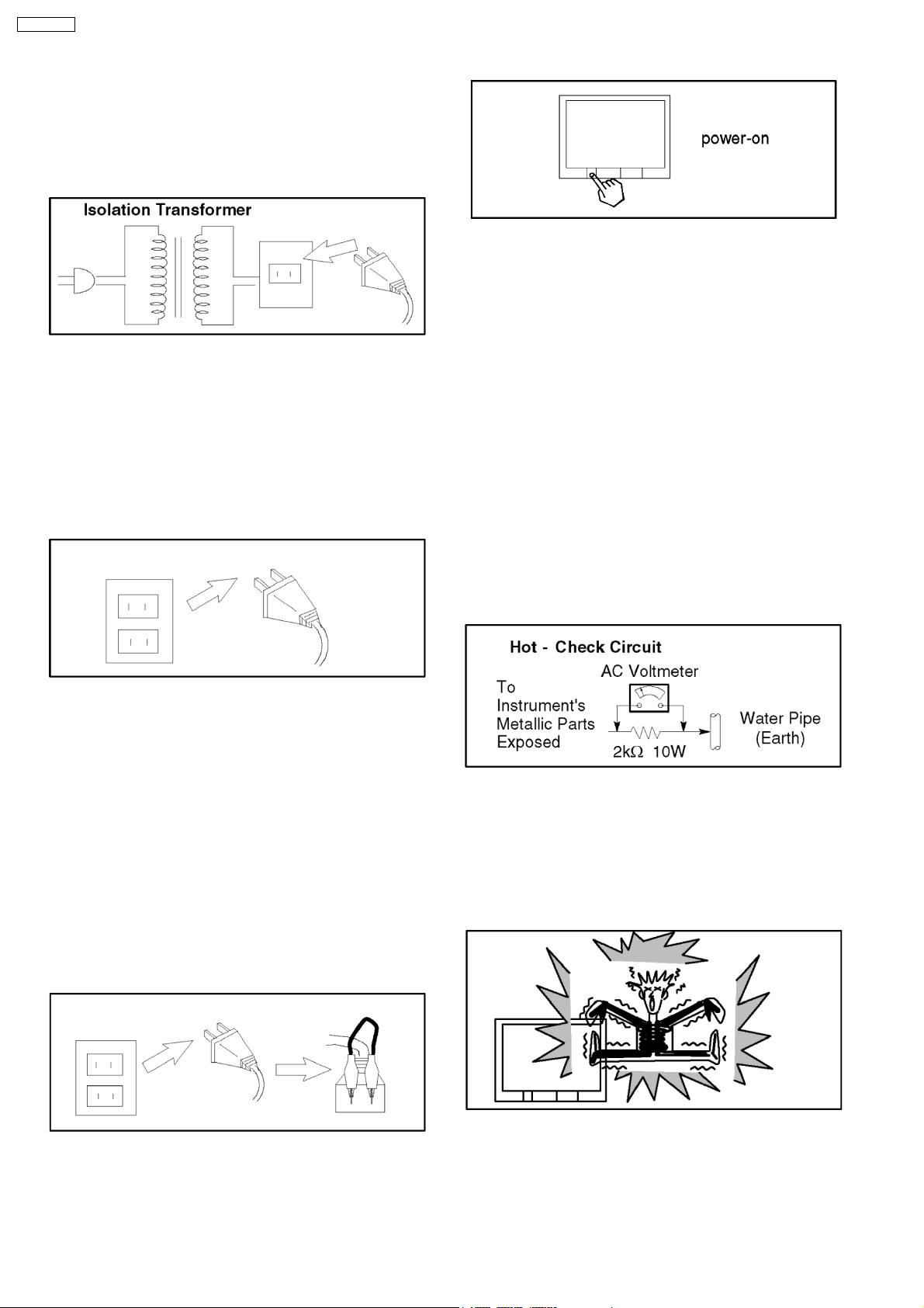
1. It is advisable to insert an isolation transformer in the AC
supply before servicing a hot chassis.
2. When servicing, observe the original lead dress, especia lly
the lead dress in the high voltage circuits. If a short circuit is
found, replace all parts which have been overheated or
damaged by the short circuit.
3. After servicing, see to it that all the protective devices such
as insulation barriers, insulation papers, shields and
isolation R-C combinations, are properly installed.
4. When the receiver is not to be used for a long period of
time, unplug the power cord from the AC outlet.
3. Measure the resistance value, with an ohmmeter, between
the jumper AC plug and each exposed metallic cabinet part
on the receiver, such as screw heads, aerials, connectors,
control shafts, etc. When the expose d metallic part has a
return path to the chassis, the reading should be between
M
and 20 M
ΩΩΩΩ
return path to the chassis, the reading must be infinite.
ΩΩΩΩ
. When the exposed metal does not have a
1.3. Leakage Current Hot Check
(See Fig. 1)
1. Plug the AC cord directly into the AC outlet. Do not use an
isolation transformer for this check.
2. Connect a 2kΩ, 10 W resistor in series with an exposed
metallic part on the receiver and an earth such as a water
pipe.
3. Use an AC voltmeter, with high impedance type, to
measure the potential across the resistor.
4. Check each exposed metallic part, and measure the
voltage at each point.
4
5. Potential, as high as
is in operation. Operation of the receiver without the rear
cover involves the danger of a shock hazard from the
receiver power supply. Servicing should not be attempted
by anyone who is not thoroughly familiar with the
precautions necessary when working on high voltage
equipment. Always discharge the anode of the picture tube
to the receiver chassis before handling the tube.
6. After servicing make the following leakage current checks to
prevent the customer from being exposed to shock
hazards.
32.0
kV is present when this receiver
1.2. Leakage Current Cold Check
1. Unplug the AC cord and connect a jumper between the two
prongs on the plug.
5. Reverse the AC plug in the AC outlet and repeat each of the
above measurements.
6. The potential any point should not exceed
case of a measurement being outside of the limits specified,
there is a possibility of a shock hazard, and the receiver
should be repaired and rechecked before it is returned to
the customer.
1.0 V rms
. In the
2. Turn on the receiver’s power switch.
4

1.4. X-Radiation
Warning:
1. The potential sources of X-Radiation in TV sets are the EHT
section and the picture tube.
2. When using a picture tube test rig for service, ensure that
the rig is capable of handling
Radiation.
Note:
It is important to use an accurate periodically calibrated
high voltage meter.
1. Set the brightness to minimum.
2. Measure the High Voltage. The meter reading should
indicate
tolerance, immediate service and correction is required to
prevent the possibility of premature component failure.
3. To prevent the possibility of X-Radiation, it is essential to
use the specified picture tube.
31.0 ± 1 kV
. If the meter indication is out of
32.0 kV
without causing X-
TX-29P190T
5
TX-29P190T
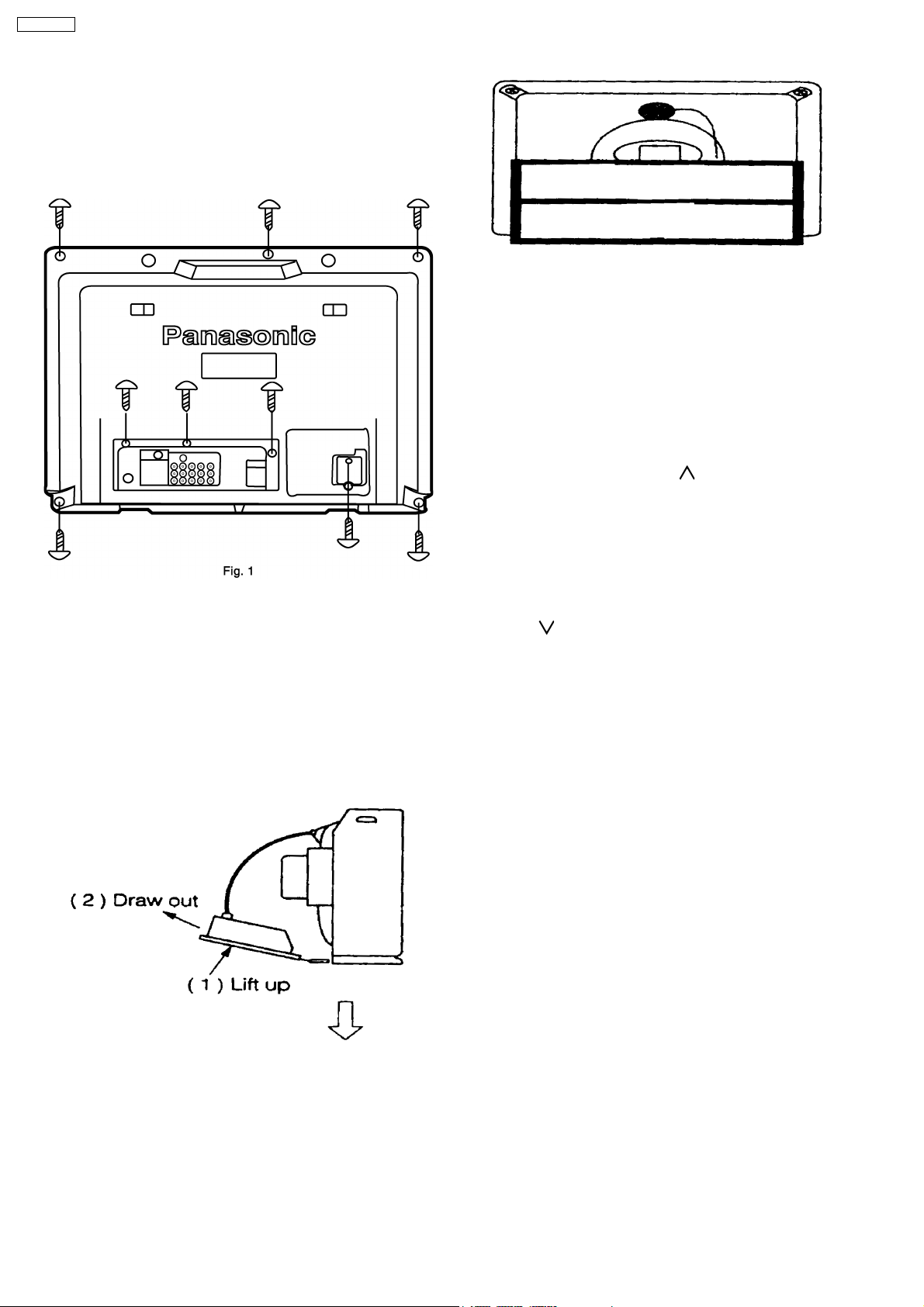
2 SERVICE HINTS
2.1. HOW TO REMOVE THE REAR
COVER
1. Remove the 9 screws as shown in Fig. 1.
2.2. HOW TO MOVE THE CHASSIS
INTO SERVICE POSITION
1. Hold and lift the rear of the chassis and gently pull the
chassis towards you as shown in Fig. 3.
2. Release the respective wiring clips and rotate the chassis
vertically through 90° anticlockwise.
3. After servicing replace the bead clamper and ensure all
wiring is returned to its original position before returning the
receiver to the customer.
2.3. HOTEL MODE
Purpose
1. At Hotels, this Mode prevents the customer from changing
the TV preset data such as Channel preset data.
Note
: This Mode is useful for Hotels. You should not get
into “Hotel mode” with Normal use.
Operation
1. To get into “Hotel Mode”, press the remote control “Recall”
button and Channel up “[+/
simultaneously, after setting the “Off-Timer” mode.
2. In this mode, the Channel up and down Function will be
enabled as normal and the maximum volume level for this
mode is set at the current volume level, i.e. the setting at
the level before entering the mode. However, other
functions will be disabled.
To exit this mode
3.
Down [-/
* This information is informed by Service Manual only.
, exit “Off-Timer” mode and the “Volume
]” key simultaneously.
]” key on the TV set
6
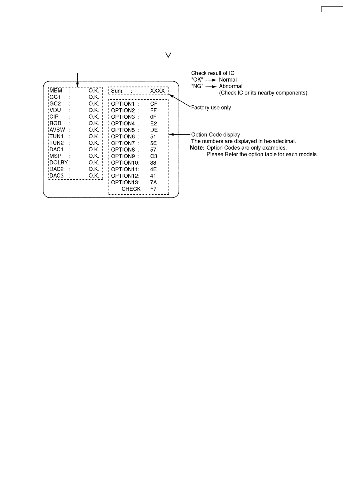
3 SELF CHECK
1. Self-Check is used to automatically check the bus lines and hexadecimal code of the TV set.
2. To get into the Self-Check mode, press the down n [-/
time pressing the HELP button on the remote control and the screen will show:
] button on the customer controls at the front of the set, at the same
TX-29P190T
7
TX-29P190T
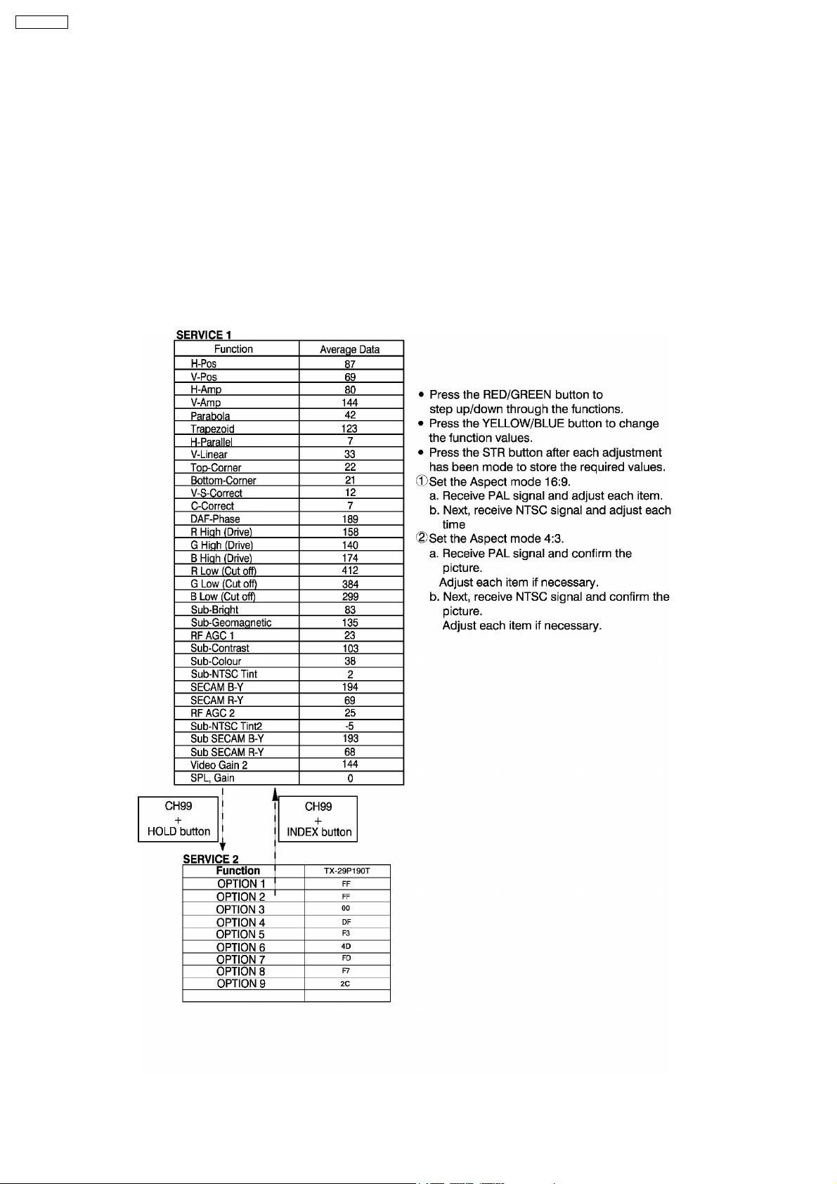
4 SERVICE MODE FUNCTION
MPU controls the functions switching for each IIC through IIC bus in this chassis. The following setting and adjustment can be
adjusted by remote control in Service Mode.
4.1. HOW TO ENTER SERVICE 1
1. In sound menu, set BASS to MAX and set TREBLE to MINIMUM.
2. Simultaneously press INDEX button on remote control and VOLUME DOWN button [-] on the TV set.
4.2. HOW TO ENTER SERVICE 2
1. Set the channel to CH99.
2. Press HOLD button on remote control.
Note
:
To exit Service mode, press N or Power button on remote control.
8
TX-29P190T
9
TX-29P190T
10
TX-29P190T
11
TX-29P190T
5 ADJUSTMENT PROCEDURE
5.1. VOLTAGE CONFIRMATION
Item / preparation
1. +B voltage
Adjustment procedure
1. TPA55: 144.8 ± 1V
2. TPA56: 12 ± 1V
3. TPA57: 9 ± 1V
4. TPA: 2.5 ± 0.25V
5.2. E.H.T CHECK
Item / preparation
1. Receive an RF signal, window or crosshatch pattern.
2. Set the Brightness and Contrast to minimum (0 Beam)
3. Connect the High Voltage Voltmeter to the CRT ANODE
CAP.
4. The set should be switched to AV (no input) contrast and
brightness minimum.
Adjustment procedure
1. Check the EHT voltage is (32.0 1.0) kV.
2. Switch from AV mode to TV.
3. With the Brightness and the contrast controls MAX, check
that the high voltage does not drop more than 3.0 kV from
the above measurement with R.F. signal.
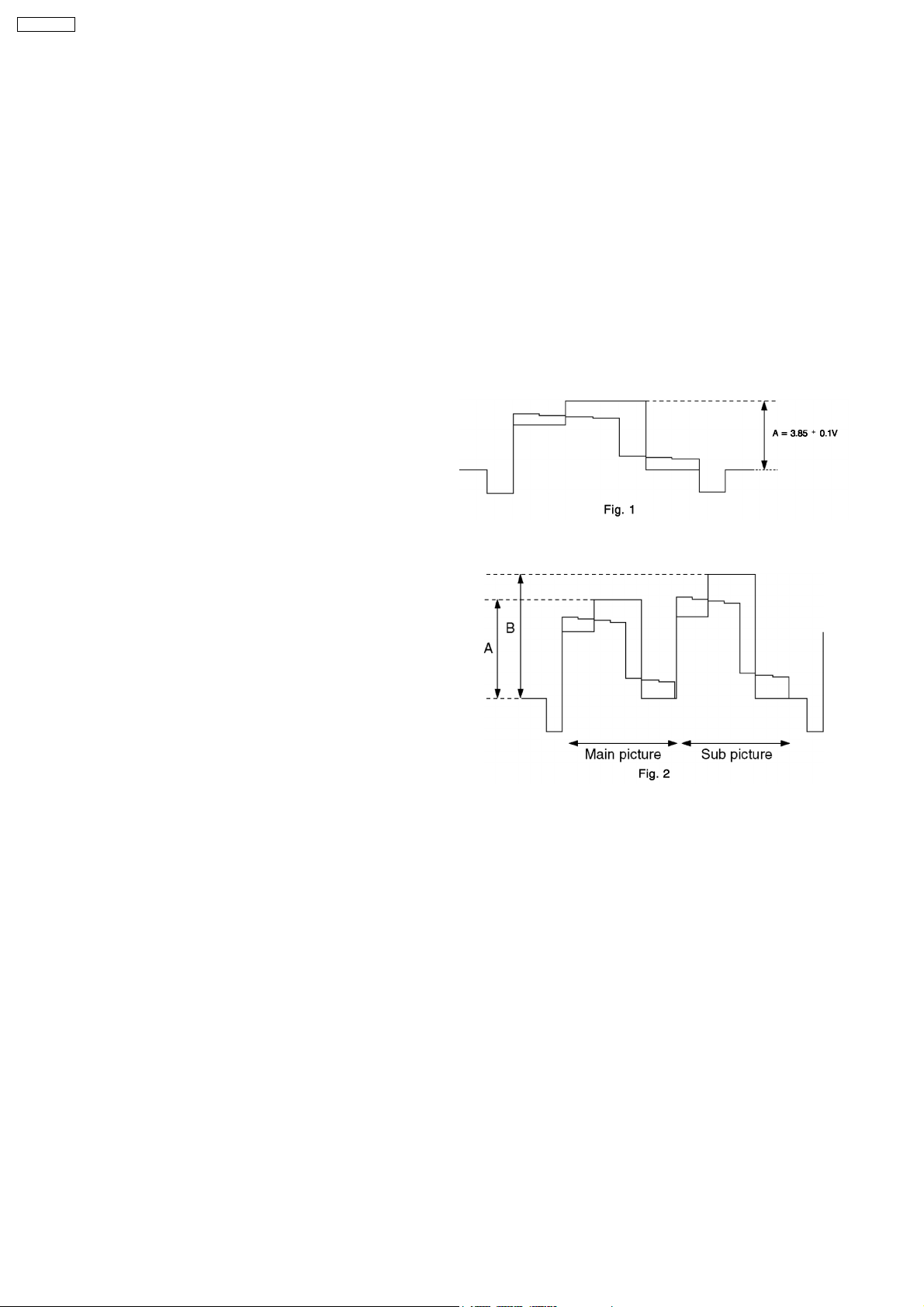
5.3. SUB CONTRAST
Item / preparation
1. Receive PAL colour bar pattern
2. Connect oscilloscope to A51 pin 48.
3. Set controls: CAP.
BRT................CENTER
COLOUR........CENTER
CONTRAST....MAX
AI....................OFF
Adjustment procedure
1. Adjust Sub Contrast (Service 1):
A = 3.85 0.1V
2. Adjust Video gain 2 (Service 1) so that Sub picture level B
becomes as same as Main picture level A.
12
TX-29P190T
5.4. SUB TINT
Item / preparation
1. Receive a 3.58 MHz NTSC rainbow pattern.
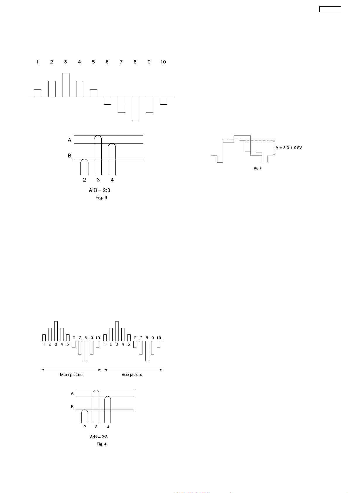
5.5. SUB COLOUR
Item / preparation
1. Receive a 3.58 MHz NTSC rainbow pattern.
2. Connect oscilloscope to A51 pin 48.
3. Set controls:
BRT................CENTER
COLOUR........CENTER
CONTRAST....MAX
AI....................OFF
Adjustment procedure
1. Adjust Sub Colour:
A = 3.3 0.5V
2. Connect oscilloscope to A51 pin 50.
3. Set controls:
BRT................CENTER
COLOUR........CENTER
CONTRAST....MAX
NTSC TINT.....CENT ER
AI....................OFF
Adjustment procedure
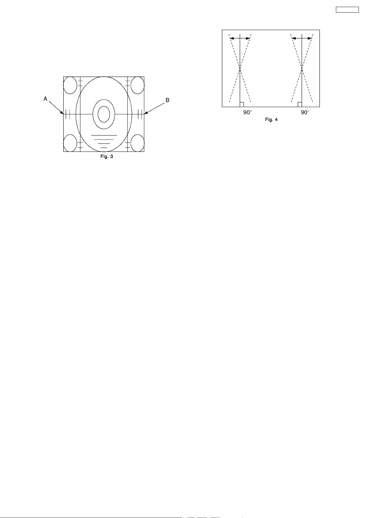
1. Adjust Sub NTSC Tint so that the peak of level of waveform
is similar to Fig. 3
2. Receive the Rainbow pattern (3.58 MHz NTSC) on both of
Main and Sub pictures.
3. Adjust Sub NTSC Tint 2 so that the peak of level of
waveform is similar to Fig. 4.
13
TX-29P190T
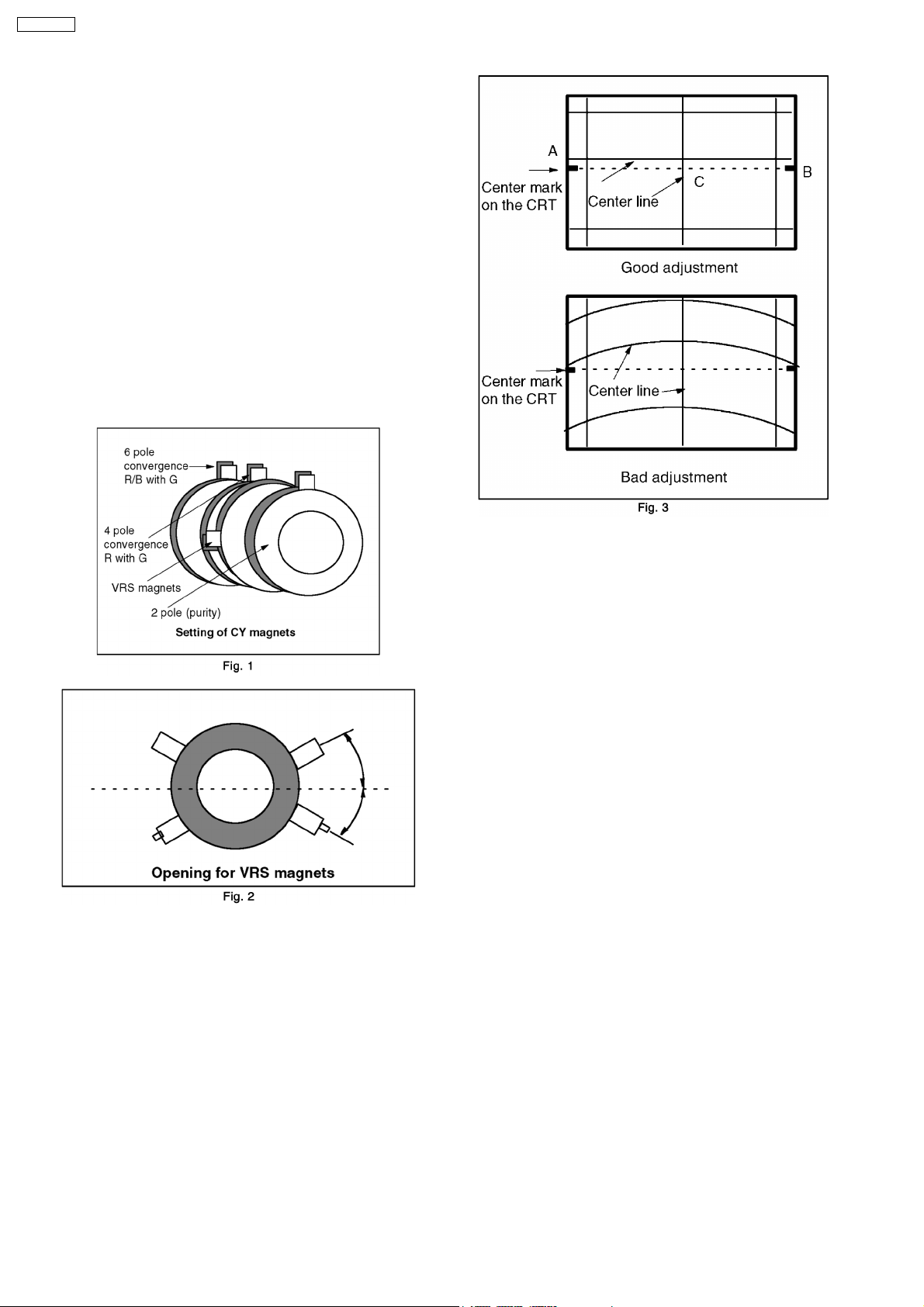
5.6. VRS ADJUSTMENT
1. PREPARATIO N
a. Set DY to CRT not to tilt up and down and left and right
deflection. (Fig. 1)
b. Set CY to CRT and set CY magnet primarily.
Pur Mg: Set Pur Mg that 2 magnets are vertical position.
VRS Mg: Set VRS Mg that 2 magnets are side position.
c. Set geomagnetic correction DAC [0].
2. ADJUSTMENT
a. Receive the white balance pattern.
b. Adjust V-CENTER.
c. Set R,B CUT OFF to minimum (0) and set G CUT OFF
to center (511).
d. Receive the aging pattern.
e. Set 2 magnets of vertical position to up and down
equally so that center part of CRT. (Fig. 3)
14
TX-29P190T
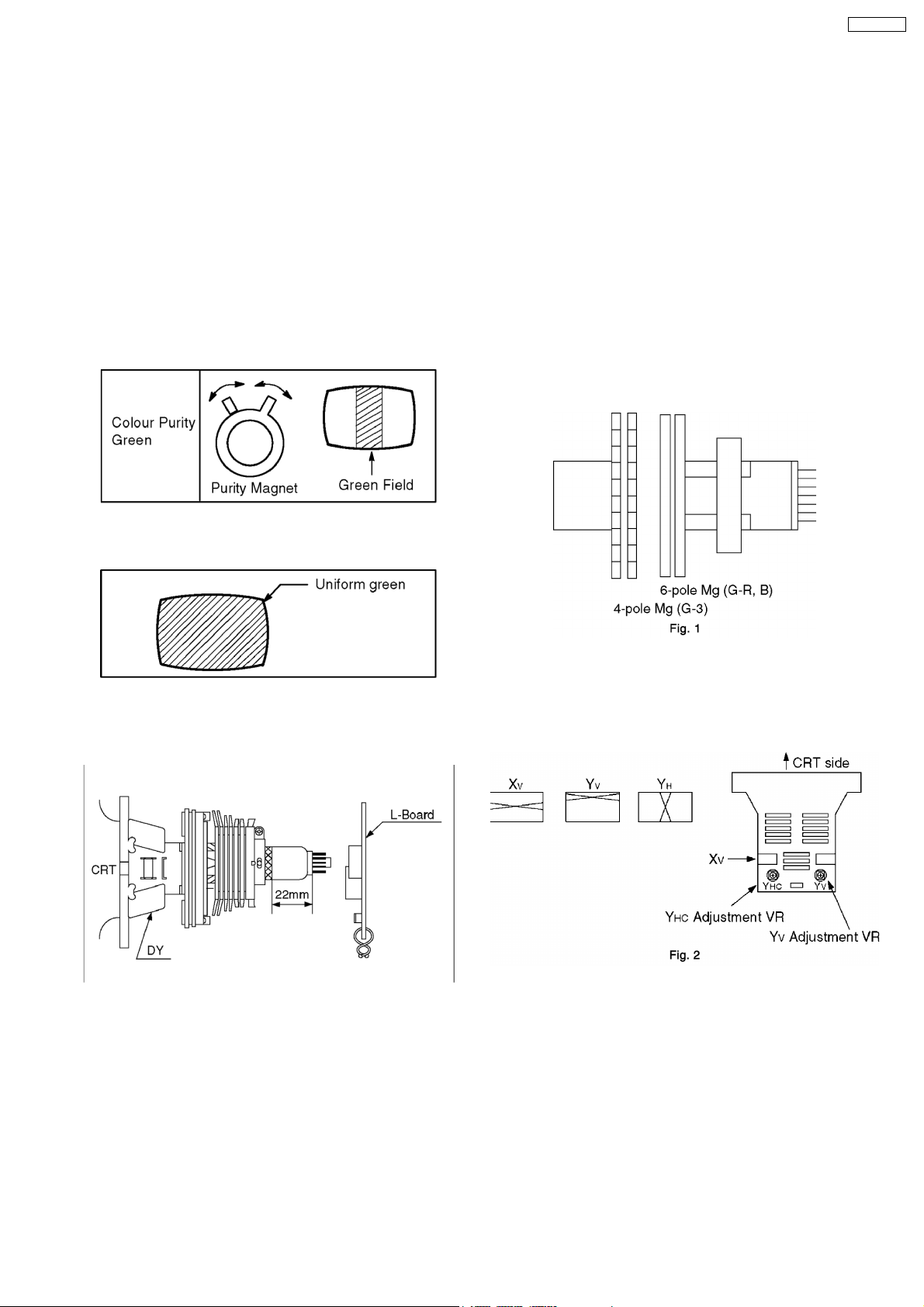
5.7. COLOUR PURITY
1. Operate the TV set for over 60 minutes.
2. Receive a purity pattern signal. (white pattern)
3. Set Bright and Contrast controls to their maximum
positions.
4. Set V-POS to 63 DAC.
5. Adjust roughly the static convergence magnets.
6. Fully degauss the picture tube using an external
degaussing coil.
7. Loosen a clamp screw for the deflection yoke and move the
deflection yoke as close to the purity magnet as possible.
8. Adjust the purity magnet so that a vertical green field is
obtained at the center of the screen.
9. Slowly press the deflection yoke and set it where a uniform
green field is obtained.
d. Set DY to CRT not to tilt (up and down and left and
right).
3. ADJUSTMENT
a. Static convergence Adjustment
a. Make sure that magnets are positioned shown in
Fig. 1.
b. Adjust 4-pole magnets (Fig. 1) to align center dots of
R and B and adjust 6-pole magnets to align center
dots to G.
c. After adjustment, secure magnets with magnet lock
of white lacquer.
*Beams move with rotating when static magnets are
turned.
Rotational reduce of beams differs by angle of two
magnets.
Therefore, repeat magnet adjustments several times
so that all are aligned completely.
10. Adjust roughly the Low Light controls and make sure that a
uniform white field is obtained.
11. Tighten the clamp screw.
5.8. CONVERGENCE
1. INSTRUMENT
a. Helmhortz device
2. PREPARATIO N
a. Set the Helmhortz device to local magnetic field.
Horizontal: 0 ± 0.03 x10
b. Receive the cross hatch pattern.
c. Picture menu: DYNAMIC Normal and adjust BRIGHT
DAC until gray portion of cross hatch.
-4
T
b. YHC, YV, XV, Adjustment (Fig. 2)
a. Adjust so that Static and Dynamic convergence is
best with YHC, VR, YV and XV coil.
In case of static convergence is tilted, repeat (1)
Static convergence Adjustment.
c. Dynamic convergence Adjustment
a. When dynamic convergence is bad, fixing permalloy
between neck and DY so that dynamic convergence
is best.
4. Confirm that left upper side line is straight.
When left upper side line isn’t straight, put magnet on DY
and adjust the left upper side line to straight.
15
TX-29P190T
5.9. CUT OFF
Preparation
1. Receive a colour bar signal with colour “OFF” and operate
the TV set more than 15 minutes.
2. Set the picture menu to “DYNAMIC NORMAL” and the AI to
off.
3. Connect an oscilloscope to TPL7 with DC mode.
4. Set the TV set to Service Mode 1.
5. Screen VR: Min.
6. Set the data level of SUB BRIGHT, R, G, B-CUTOFF and
R, G, B-DRIVE to the table values.
•
•
R High (R-CUT OFF) - 256
• •
•
•
G High (G-CUT OFF) - 512
• •
•
•
B High (B-CUT OFF) - 256
• •
•
•
R Low (R-DRIVE) - 128
• •
•
•
G Low (G-DRIVE) - 128
• •
•
•
B Low (B-DRIVE) - 128
• •
•
•
SUB RIGHT - 136
• •
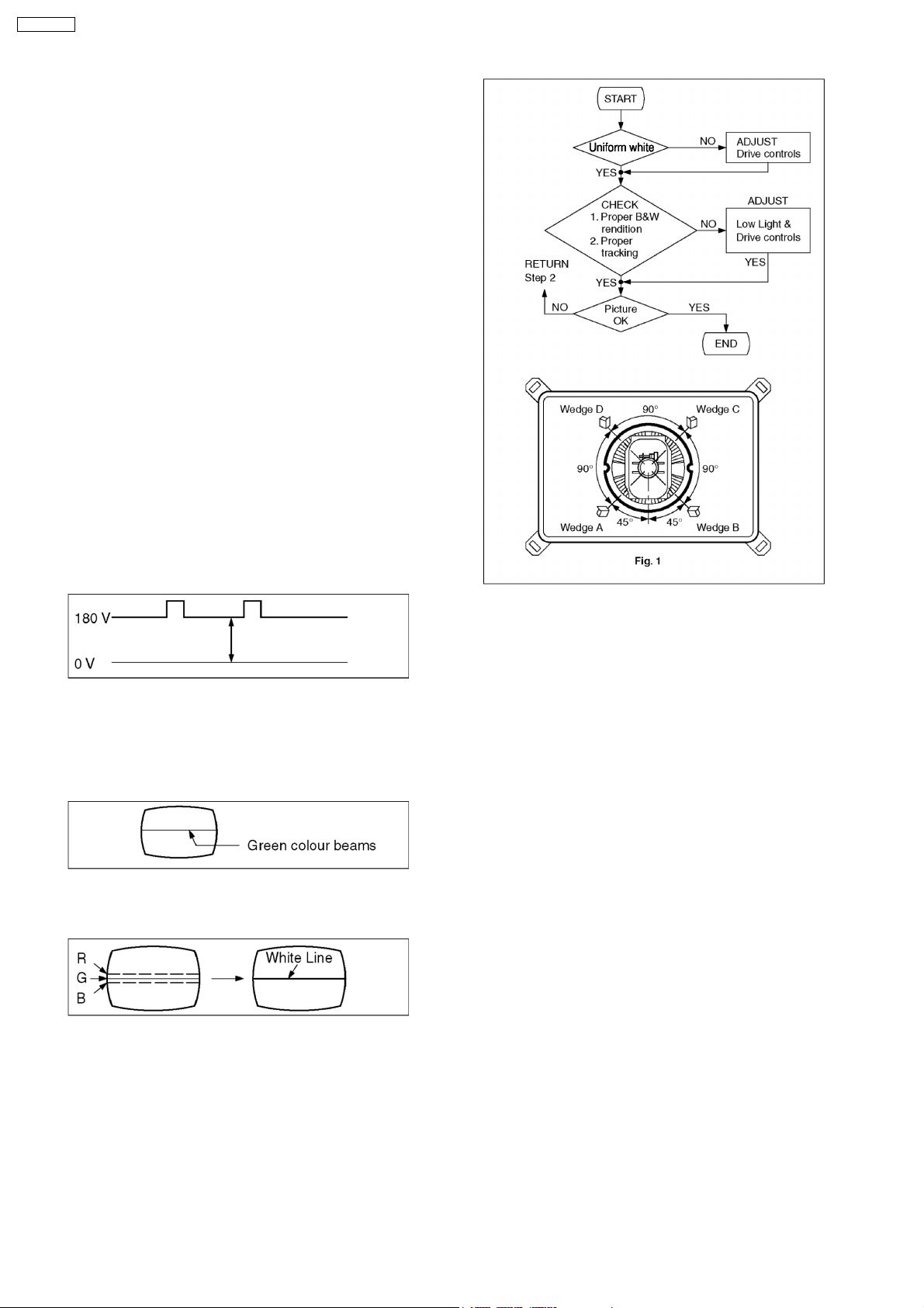
Adjustment
1. Select G-CUTOFF adjustment mode and collapse vertical
scan.
2. Adjust G-CUTOFF control to become the DC = 0V to video
level at 180V as shown below.
3. Slowly turn the screen control clockwise until a green colour
horizontal line appears on the picture tube. This is the
setting point for the screen control.
Note that do not adjust the G-CUTOFF setting in the
following procedure.
4. Adjust the remained R and B-CUTOFF controls so as to get
a white horizontal line on the screen.
5. Return to full field SCAN by pushing the position 5 key on
the remote control.
6. Adjust the R-Drive and B-Drive controls as to obtain uniform
white on the white bar of the greyscale pattern.
7. Confirm correct B/W rendition and greyscale tracking or
repeat CUTOFF and drive control setup.
Note
:
Write down the original value for each address
adjusment before adjusting anything.
8. Wedge A shown in Fig. 1 should be fixed within a range of
45° to the left of the vertical line as shown.
9. After inserting wedge A, insert wedges B, C and D.
The wedges should be set 90° apart from each other.
10. Be certain that the four wedges are firmly fixed and the
deflection yoke is tightly clamped in place otherwise the
deflection yoke may shift its position and cause a loss of
convergence and purity.
16
TX-29P190T
5.10. WHITE BALANCE
Item / preparation
1. Select Service Mode 1.
2. Aging should have been performed over 30 minutes.
3. Receive the white balance pattern.
4. Picture menu: DYNAMIC NORMAL.
AI: OFF
5. Degauss the CRT face.
6. Connect the photo sensors of the Colour Analyser to the
CRT.
Note
:
CRT cut off adjustment is completed.
Adjustment procedure
1. Adjustment of Low Light
Adjustment SUB BRIGHT, so that “Y” axis indicates 6.5
Adjustment R-CUT OFF, so that y axis indicates 0.248.
Adjustment B-CUT OFF, so that x axis indicates 0.247
2. Adjustment of High Light
Adjust SUB BRIGHT, so that “Y” axis indicates 150.
Adjust R-DRIVE, so that y axis indicates 0.264.
Adjust B-DRIVE, so that x axis indicates 0.258.
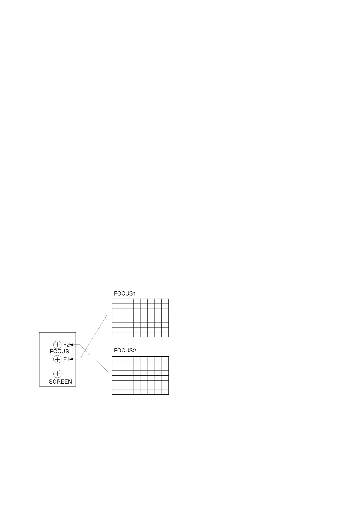
5.11. FOCUS
Item / preparation
1. Receive a cross-hatch pattern signal.
Adjustment procedure
1. Adjust the Focus to thin all the Lines by Focus 1 Control.
(Prefer to thin the Vertical Lines than Horizontal Line.)
2. Adjust the Focus to thin the Horizontal Lines by Focus 2
Control.
5.12. GEOMAGNETIC
Item / preparation
1. Demagnetize the GM-Board around its perimeter with the
Demagnetizer.
2. Set to control:
Geomagnetic.....Auto
Adjustment procedure
1. Connect a DC voltage meter to TPGM1-2pin (GM-Board)
2. Adjust the R4863 (GM-Board) so that the Vx Out at
TPGM1-2pin becomes 4.9 0.05 V
3. Connect a DC voltage meter to TPGM1-1pin (GM Board)
4. Adjust the R4861 (GM-Board) so that the Vy Out at
TPGM1-1pin becomes 4.9 0.05 V
5.13. SUB BRIGHT
Item / preparation
1. Receive the sub bright pattern.
2. Picture Menu:
BRT..................CENTER
COLOUR..........CENTER
CONT...............MAX
3. Connect the photo sensor of the Colour Analyser to the
center of the CRT.
Adjustment procedure
1. Adjust Sub Bright so that brightness level becomes 1 0.2
cd/m2.
17
TX-29P190T
6 DEFLECTION ADJUSTMENT
6.1. V-ADJUSTMENT/
CONFIRMATION (4:3 MODE)
6.1.1. V-CENTER ADJUSTMENT (4:3
MODE)
6.1.1.1. 100i V-POS ADJUSTMENT
1. Receive PAL monoscope pattern.
2. Set scan mode to 100Hz by remote control key.
3. Adjust V-POS (100i / 4:3) so that the scale of the top and
bottom side is equal.
6.1.1.2. 120i V-POS ADJUSTMENT
1. Receive NTSC monoscope pattern.
2. Set scan mode to 100Hz by remote control key.
3. Adjust V-POS (120i / 4:3) so that the scale of the top and
bottom side is equal.
6.1.1.3. 50p V-POS ADJUSTMENT
1. Receive PAL monoscope pattern.
2. Set scan mode to progressive by remote control key.
3. Adjust V-POS (50p / 4:3) so that the scale of the top and
bottom side is equal.
6.1.1.4. 60p V-POS ADJUSTMENT
1. Receive NTSC monoscope pattern.
2. Set scan mode to progressive by remote control key.
3. Adjust V-POS (60p / 4:3) so that the scale of the top and
bottom side is equal.
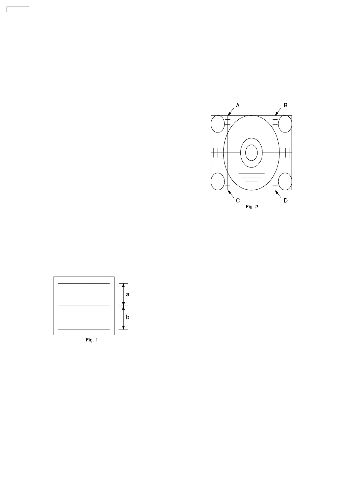
2. Set scan mode to progressive by remote control key.
3. Adjust V-AMP (50p / 4:3) so that B, D (Fig. 2) is 2.1 ± 0.1.
6.1.2.4. 60p V-AMP ADJUSTMENT
1. Receive NTSC monoscope pattern.
2. Set scan mode to progressive by remote control key.
3. Adjust V-AMP (60p / 4:3) so that B, D (Fig. 2) is 2.1± 0.1.
6.2. H-DEFLECTION
CONFIRMATION/ADJUSTMENT
(4:3 MODE)
6.2.1. H-CENTER ADJUSTMENT (4:3
MODE)
6.2.1.1. 100i H-POS ADJUSTMENT
6.1.2. V-HEIGHT ADJUSTMENT (4:3
MODE)
6.1.2.1. 100i V-AMP ADJUSTMENT
1. Receive PAL monoscope pattern.
2. Set scan mode to 100 Hz by remote control key.
3. Adjust V-AMP (100i / 4:3) so that B, D (Fig. 2) is 2.1 ± 0.1.
6.1.2.2. 120i V-AMP ADJUSTMENT
1. Receive NTSC monoscope pattern.
2. Set scan mode to 100 Hz by remote control key.
3. Adjust V-AMP (120i / 4:3) so that B, D (Fig. 2) is 2.1 ± 0.1.
6.1.2.3. 50p V-AMP ADJUSTMENT
1. Receive PAL monoscope pattern.
2. Set scan mode to 100 Hz by remote control key.
3. Adjust H-POS (100i / 4:3) so that the horizontal position is
center of CRT.
6.2.1.2. 120i H-POS ADJUSTMENT
1. Receive NTSC monoscope pattern.
2. Set scan mode to 100 Hz by remote control key.
3. Adjust H-POS (120i / 4:3) so that the horizontal position is
center of CRT.
6.2.2. H-WIDTH ADJUSTMENT (4:3
MODE)
6.2.2.1. 100i H-AMP ADJUSTMENT
1. Receive PAL monoscope pattern.
2. Set scan mode to 100 Hz by remote control key.
3. Adjust H-AMP (100i / 4:3) so that both of the edges are
within A, B = 2.5 ± 0.2.
1. Receive PAL monoscope pattern.
18
6.2.2.2. 120i H-AMP ADJUSTMENT
1. Receive NTSC monoscope pattern.
2. Set scan mode to 100 Hz by remote control key.
3. Adjust H-AMP (120i / 4:3) so that both of the edges are
within A, B = 2.5 ± 0.2.
6.3. EW
ADJUSTMENT/CONFIRMATION
(4:3 MODE)
6.3.1. 100i SIDE EW ADJUSTMENT (4:3
MODE)
1. Receive PAL cross-hatch pattern.
2. Set scan mode to 100 Hz by remote control key.
3. Adjust the vertical line to straight by Parabola (100i / 4:3).
4. Adjust the vertical line to straight line of both sides vertical
line in Fig. 4 by Trapezoid (100i / 4:3).
5. Confirm there is no H-parallel distortion.
If there is distortion, adjust by H-Parallel (100i / 4:3).
In that case, repeat 4 and 5 so that there is no trapezoid /
parallel distortion.
6. Confirmation EW of the corner side.
If need, adjust Top-Corner (100i / 4:3) and Bottom Corner
(100i / 4:3).
7. Confirm bow level of the both side.
If it is not symmetrical, adjust C-Correct (100i / 4:3).
6.3.2. 120i EW ADJUSTMENT (4:3 MODE)
1. Receive NTSC cross-hatch pattern.
2. Set scan mode to 100 Hz by remote control key.
3. Adjust the vertical line to straight by Parabola (120i / 4:3).
4. Adjust the vertical line to straight line of both sides vertical
line in Fig. 4 by Trapezoid (120i / 4:3).
5. Confirm there is no H-parallel distortion.
If there is distortion, adjust by H-Parallel (120i / 4:3).
In that case, repeat 4 and 5 so that there is no trapezoid /
parallel distortion.
6. Confirmation EW of the corner side.
If need, adjust Top-Corner (120i / 4:3) and Bottom Corner
(120i / 4:3).
7. Confirm bow level of the both side.
If it is not symmetrical, adjust C-Correct (120i / 4:3).
TX-29P190T
6.3.3. 50p EW ADJUSTMENT (4:3 MODE)
1. Receive PAL cross-hatch pattern.
2. Set scan mode to progressive by remote control key.
3. Adjust the vertical line to straight by Parabola (50p / 4:3).
4. Adjust the vertical line to straight line of both sides vertical
line in Fig. 5 by Trapezoid (50p / 4:3).
5. Confirm there is no H-parallel distortion.
If there is distortion, adjust by H-Parallel (50p / 4:3).
In that case, repeat 4 and 5 so that there is no trapezoid /
parallel distortion.
6. Confirmation EW of the corner side.
If need, adjust Top-Corner (50p / 4:3) and Bottom Corner
(50p / 4:3).
7. Confirm bow level of the both side.
If it is not symmetrical, adjust C-Correct (50p / 4:3).
6.3.4. 60p SIDE PINCUSSION
ADJUSTMENT (4:3 MODE)
1. Receive NTSC cross-hatch pattern.
2. Set scan mode to progressive by remote control key.
3. Adjust the vertical line to straight by Parabola (60p / 4:3).
4. Adjust the vertical line to straight line of both sides vertical
line in Fig. 5 by Trapezoid (60p / 4:3).
5. Confirm there is no H-parallel distortion.
If there is distortion, adjust by H-Parallel (60p / 4:3).
In that case, repeat 4 and 5 so that there is no trapezoid /
parallel distortion.
6. Confirmation EW of the corner side.
If need, adjust Top-Corner (60p / 4:3) and Bottom Corner
(60p / 4:3).
7. Confirm bow level of the both side.
If it is not symmetrical, adjust C-Correct (60p / 4:3).
19
 Loading...