

Panasonic TX-25P80T Service Manual
TX-25P80T
MX-10 Chassis
Order No. MTV0110238C3
Colour Television
Specification
Power Source AC Auto 110-240 V, 50/60 Hz
Power Consumption 138 W
Standby condition : 0.8 W
Aerial Terminal Impedance : 75Ω, Coaxial type
Tuning System Frequency Synthesizer
Auto Search Tuning
Pos : 100 Positions
Receiving System 17 Systems
Receiving Channels Regular TV
VHF BAND
UHF BAND
21-69 (PAL G,H,I/SECAM G,K,K1)
CATV
Intermediate Frequency
2-12 (PAL/SECAM B, K1)
0-12 (PAL B AUST.)
1-9 (PAL B N.Z.)
1-12 (PAL/SECAM D)
1-12 (NTSC M Japan)
2-13 (NTSC M U.S.A.)
28-69 (PAL B AUST.)
13-57 (PAL D,K)
13-62 (NTSC M Japan)
14-69 (NTSC M U.S.A.)
S1-S20 (OSCAR)
1-125 (U.S.A. CATV)
C13-C49 (JAPAN)
S21-S41 (HYPER)
Z1-Z37 (CHINA)
Video
Sound
Colour
Receiving Stereo Sound System QUADRA STEREO / TEXT
Video/Audio/Terminals
AV 1, 2, 3
Y/PB/PR
Monitor Out
High Voltage 31.0 (+0.7, -1.5kV) at zero beam
Picture Tube A60LUQ085X Type 25 (60 cm)
Audio Output 16 W speaker
Dimensions (WxDxH) 634 mm x 471 mm x 534 mm
Weight (Mass) 37 kg (Net)
Accessories Supplied
Remote Control Transmitter 1. R6(AA) Battery x 2
31.5 MHz (D,K) / 32.5 MHz (B,G)
32.0 MHz (I) / 32.5 MHz (M)
33.57 MHz (PAL) /
33.6 MHz (SECAM)
34.42 MHz (NTSC) /
33.75 MHz (SECAM)
IN S-Video Y:1.0Vp-p 75Ω
DVD IN S-Video C:0.3Vp-p 75Ω
(Phone type) Y:1.0Vp-p 75Ω PB,
PR:0.7Vp-p 75Ω Video 1.0Vp-p
75Ω Audio Approx. 400mV 47KΩ
Video 1,0Vp-p 75Ω
Audio Approx. 400mV 47KΩ
Measured diagonally, 104°
38.0 MHz
current
deflection
© 2001 Matsushita Electric Industrial Co., Ltd. All
rights reserved. Unauthorized copying and
distribution is a violation of law.
TX-25P80T
Partlist
Note:
Specifications are subject to change without notice. Mass and
Dimensions shown are approximate.
CONTENTS
Page Page
1 Safety Precautions
1.1. General Guide
1.2. Leakage Current Cold Check
1.3. Leakage Current Hot Check (See Fig. 1)
1.4. X-Radiation
2 Location of Controls and Circuit Boards
2.1. BACK VIEW
2.2. LOCATION AND FUNCTION NAME OF CIRCUIT BOARD
3 Service Hints
3.1. HOW TO MOVE CHASSIS INTO SERVICE POSITION.
4 MARKET MODE FUNCTION
5 ADJUSTMENT PROCEDURE
5.1. B VOLTAGE
5.2. RF AGC
5.3. HIGH VOLTAGE
5.4. SUB TINT
5.5. SUB CONTRAST
5.6. PAL COLOUR OUTPUT
5.7. NTSC COLOUR OUTPUT
3
3
3
3
3
4
4
4
5
5
6
8
8
8
8
8
8
9
9
5.8. COLOUR PURITY
5.9. CONVERGENCE
5.10. WHITE BALANCE (MARKET MODE CHK 3)
6 CONDUCTOR VIEWS
6.1. T-Board (TNP4G115AH) and L-Board (TNP4G107AW)
6.2. A-Board (TNP4G164AQ)
6.3. H-Board (TNP4G173AB), X-Board (TNP4G108BC) and
7 SCHEMATIC DIAGRAMS
7.1. SCHEMATIC DIAGRAM FOR MODEL TX-25P80T (MX10A CHASSIS)
7.2. Main Board (TNP4G164AQ)
7.3. Rear AV Circuit (TNP4G173AB)
7.4. CRT Circuit (TNP4G107AW)
7.5. Pincushion Circuit (TNP4G108BC)
7.6. Teletext Circuit (TNP4G115AH)
9 Replacement Parts List
9.1. Replacement Parts List Notes
9.2. Replacement Parts List
10
10
11
13
13
14
16
17
17
18
20
21
22
23
27
29
29
30
2
TX-25P80T
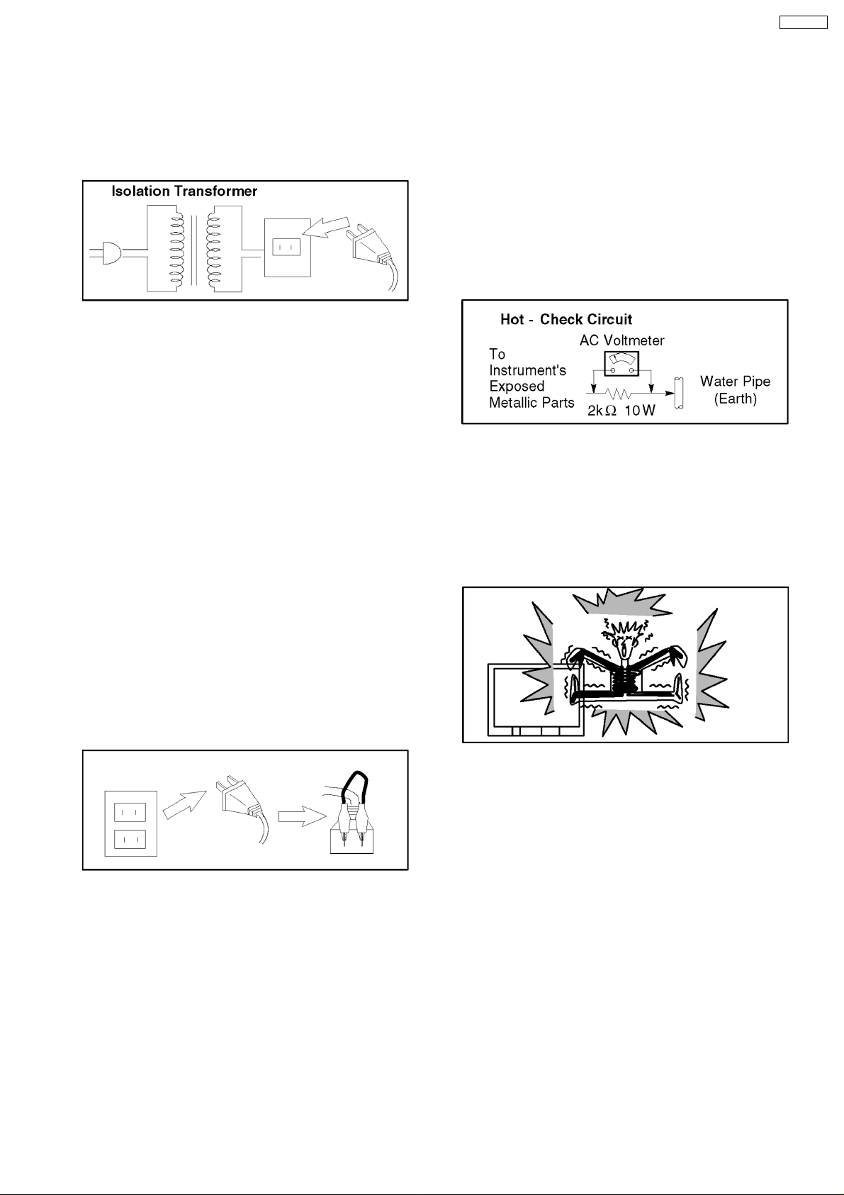
1 Safety Precautions
1.1. General Guide
1. It is advisable to insert an isolation transformer in the AC
supply before servicing a hot chassis. Fig. 1.
Fig. 1
2. When servicing, observe the original lead dress, especially
the lead dress in the high voltage circuits. If a short circuit is
found, replace all parts which have been overheated or
damaged by the short circuit.
3. After servicing, observe that all the protective devices such
as insulation barriers, insulation papers, shields, and
isolation R-C combinations, are properly installed.
4. When the receiver is not to be used for a long period of
time, unplug the power cord from the AC outlet.
5. Potential, as high as
is in operation. Operation of the receiver without the
receiver power supply. Servicing should not be attempted
by anyone who is not thoroughly familiar with the
precautions necessary when working on high voltage
equipment. Always discharge the anode of the picture tube
to the receiver chassis before handling the tube.
After servicing make the following leakage current checks to
prevent the customer from being exposed to shock
hazards.
30.0
kV is present when this receiver
1.3. Leakage Current Hot Check
(See Fig. 1)
1. Plug the AC cord directly into the AC outlet. Do not use an
isolation transformer for this check.
2. Connect a 2 kΩ, 10 W resistor in series with an exposed
metallic part on the receiver and an earth such as a water
pipe.
3. Use an AC voltmeter, with high impedance type, to
measure the potential across the resistor.
4. Check each exposed metallic part, and measure the
voltage at each point. Fig. 3.
Fig. 3
5. Reverse the ACplug in the AC outlet and repeat each of the
above measurements.
6. The potential any point should not exceed
case of a measurement being outside of the limits specified,
there is a possibility of a shock hazard, and the receiver
should be repaired and re-checked before it is returned to
the customer. Fig. 4.
1.0 V rms
. In the
1.2. Leakage Current Cold Check
1. Unplug the AC cord and connect a jumper between the two
prongs on the plug. Fig. 2.
Fig. 2
2. Turn on the receiver’s power switch.
3. Measure the resistance value, with an ohmmeter, between
the jumpered AC plug and each exposed metallic cabinet
part on the receiver, such as screw heads, aerials,
connectors, control shafts, etc. When the exposed metallic
part has a return path to the chassis, the reading should be
ΩΩΩΩ
4M
between
not have a return path to the chassis, the reading must be
zero.
and 20 M
ΩΩΩΩ
. When the exposed metal does
Fig. 4
1.4. X-Radiation
Warning :
1. The potential sources of X-Radiation in TV sets are the EHT
section and the picture tube.
2. When using a picture tube test rig for service, ensure that
the rig is capable of handling
Radiation.
Note:
It is important to use an accurate periodically calibrated
high voltage meter.
1. Set the brightness to minimum.
2. Measure the High Voltage. The meter reading should
indicate
tolerance, immediate service and correction is required to
prevent the possibility of premature component failure.
3. To prevent the possibility of X-Radiation, it is essential to
use the specified picture tube.
30.0 +0.7, -1.5kV
28.5 kV
. If the meter indication is out of
without causing X-
3
TX-25P80T
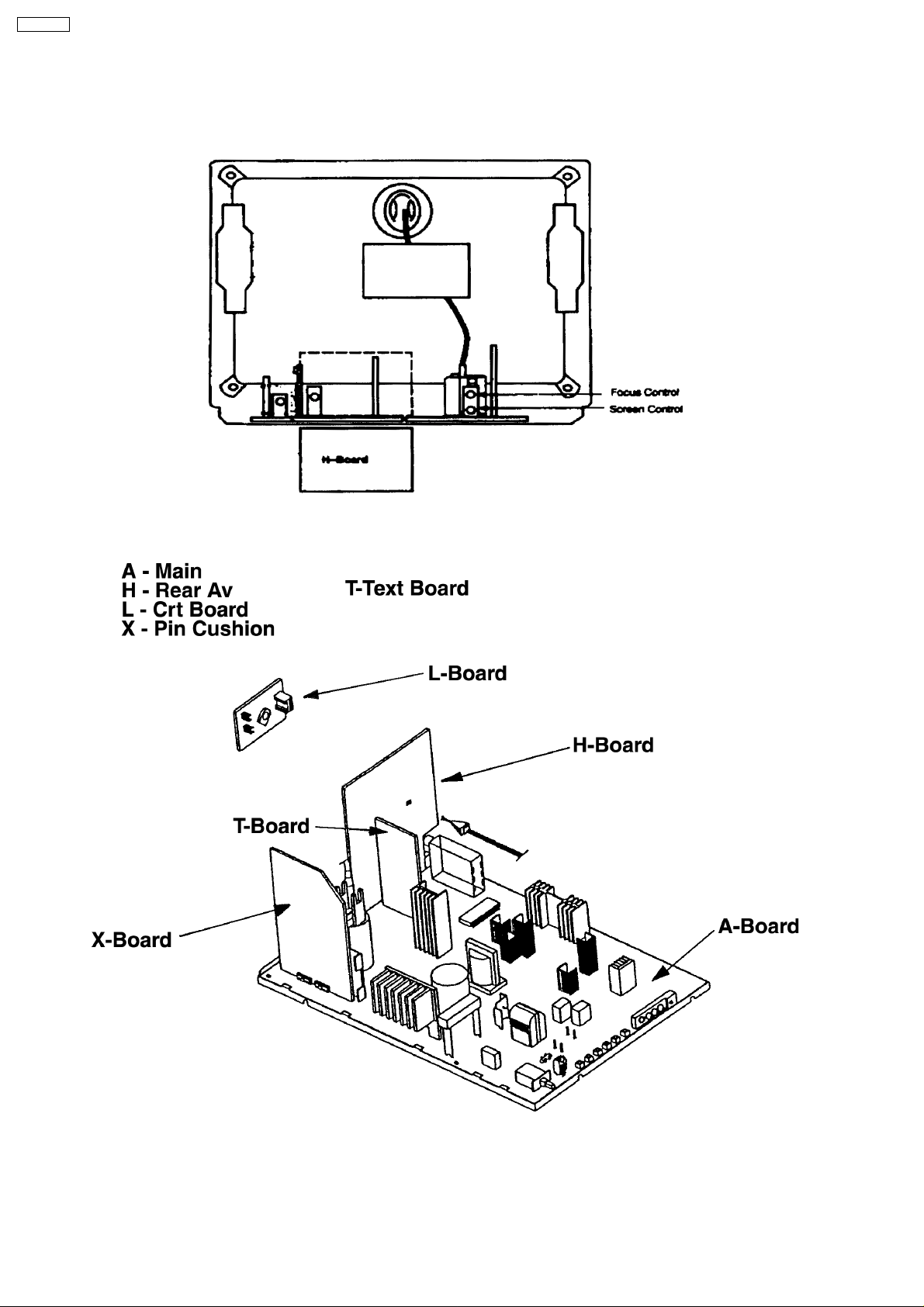
2 Location of Controls and Circuit Boards
2.1. BACK VIEW
2.2. LOCATION AND FUNCTION NAME OF CIRCUIT BOARD
4
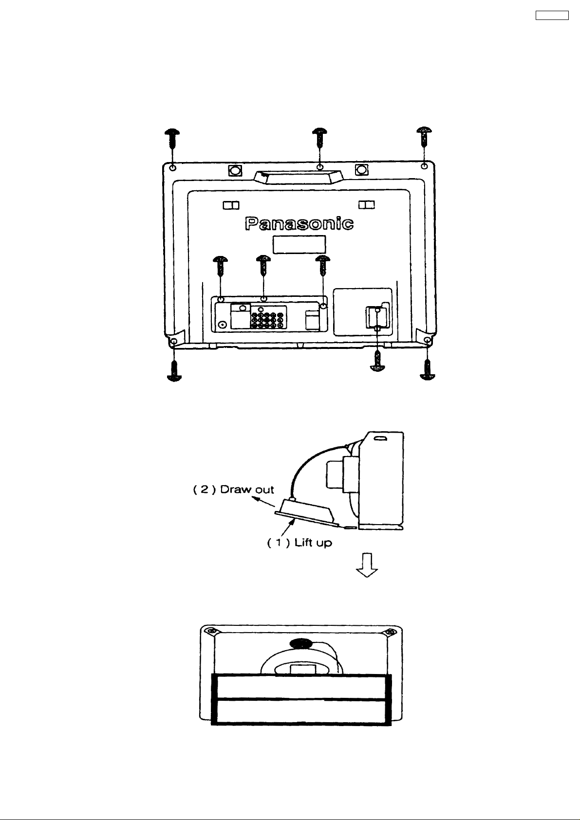
3 Service Hints
3.1. HOW TO MOVE CHASSIS INTO SERVICE POSITION.
1. Remove 9 screws.
TX-25P80T
2. Draw out Main Chassis.
3. Stand the Main Chassis.
5
TX-25P80T
4 MARKET MODE FUNCTION
Outline:
MPU controls the functions switching for each ICs through IIC bus in this chassis. The following setting and adjustment can be
adjusted by remote control in Market Mode.
1. Selection of Market Mode
Adjust the VOLUME “zero” and set OFF TIMER Button to 30 min. Then, simultaneously press the RECALL Button on the
remote control and the VOLUME DOWN button - the TV set.
2. Selection of CHK Mode
Cursor moves each CHK Mode by pressing “1” or “2” of 10 key button on the remote control.
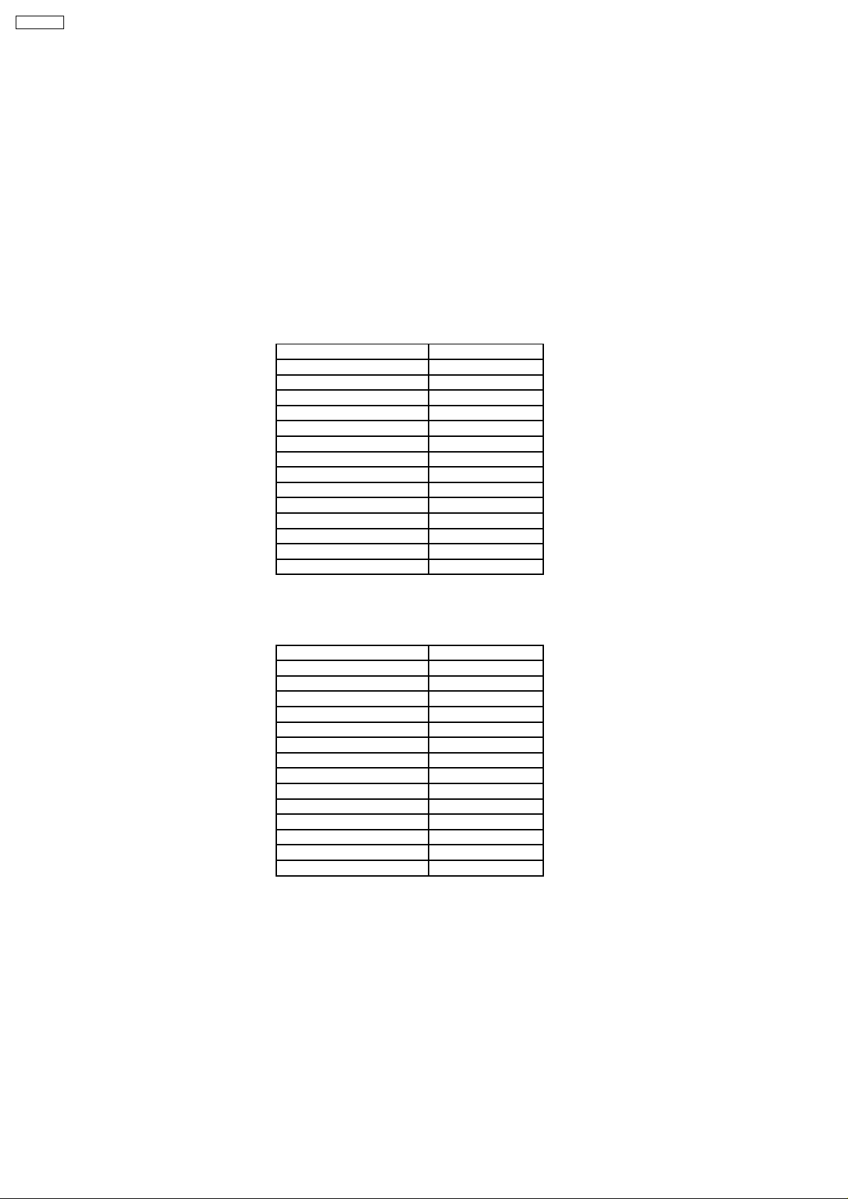
1. Option Code Setting Mode (CHK 1)
If the memory IC (IC1102) is replaced, option code should be re-memorized. Option code can be changed by pressing Volume
“+” or “-” button. To memorize, press “0” of the 10 key button.
Display Adj. Range
COLOUR SYSTEM 0~6
MX 10A OFF / ON
C4 BIT OFF / ON
NOISE MUTE OFF / ON
SPEED OFF / ON
VCR / GAME OFF / ON
YUV OFF / ON
AV3 OFF / ON
STEREO OFF / ON
GEO 0~2
SASO 0~2
TEXT OFF / ON
PANA DISPLAY OFF / ON
SOUND SYS 0~5
2. VCJ Adjustment Mode
To change the screen (item) in CHK mode, press “3” or “4” of the 10 key button. Then the Date and Level changes by pressing
Volume “+” or “-” button.
Display Adj. Range
SUB COLOUR 00H ~ 3FH
COLOUR 0~63
RF AGC 00H ~ FFH
SECAM B-Y 00H ~ 0FH
SECAM R-Y 00H ~ 0FH
B-Y 00H ~ 0FH
R-Y 00H ~ 0FH
SUB TEXT CONT 00H ~ 3FH
SHARPNESS 0~63
SUB Y CONT 00H ~ 3FH
CONT 0~63
SUB BRIGHT 00H ~ FFH
BRIGHT 0~63
SUB NTS-TINT 00H ~ 3FH
6
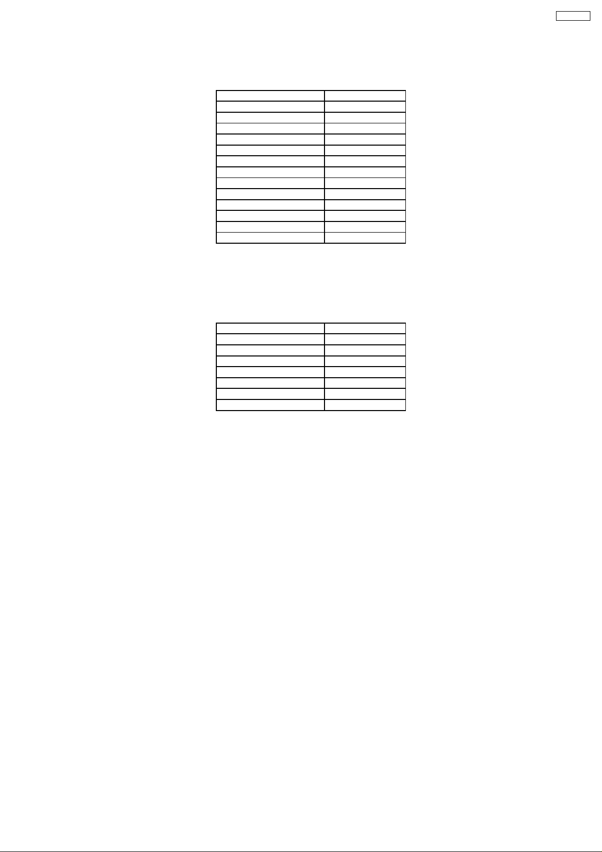
3. Pincushion Adjustment Mode
To change the screen (item) in CHK mode, press “3” or “4” of the 10 key buttons. Then the Date and Level changes by pressing
Volume “+” or “-” button.
Display Adj. Range
PARABOLA 00H ~ 3FH
60 V-HEIGHT 00H ~ 3FH
50 V-HEIGHT 00H ~ 3FH
SUB GEO 00H ~ 3FH
GEOMAGNETIC -9 AUTO 9
V CENTER 00H ~ 07H
50Hz CENTER 00H ~ 1FH
EW-CORNER 1 00H ~ 0FH
TRAPEZOID 00H ~ 3FH
V-LINEAR 00H ~ 3FH
60 VS CORRECT 00H ~ 3FH
50 VS CORRECT 00H ~ 3FH
H-WIDTH 00H ~ 3FH
Note : Picture will be changed to one horizontal line by pressing “5” of the 10 key button in the remote control. (1 - 5).
4. White Balance Adjustment Mode
To change the screen (item) in CHK mode, press “3” or “4” of the 10 key buttons. Then the Date and Level changes by pressing
Volume “+” or “-” button.
Display Adj. Range
B. DR 00H ~ FFH
G. DR 00H ~ FFH
SUB.BR 00H ~ FFH
BRIGHT 0~63
B - CUT 00H ~ FFH
G - CUT 00H ~ FFH
R - CUT 00H ~ FFH
TX-25P80T
7
TX-25P80T
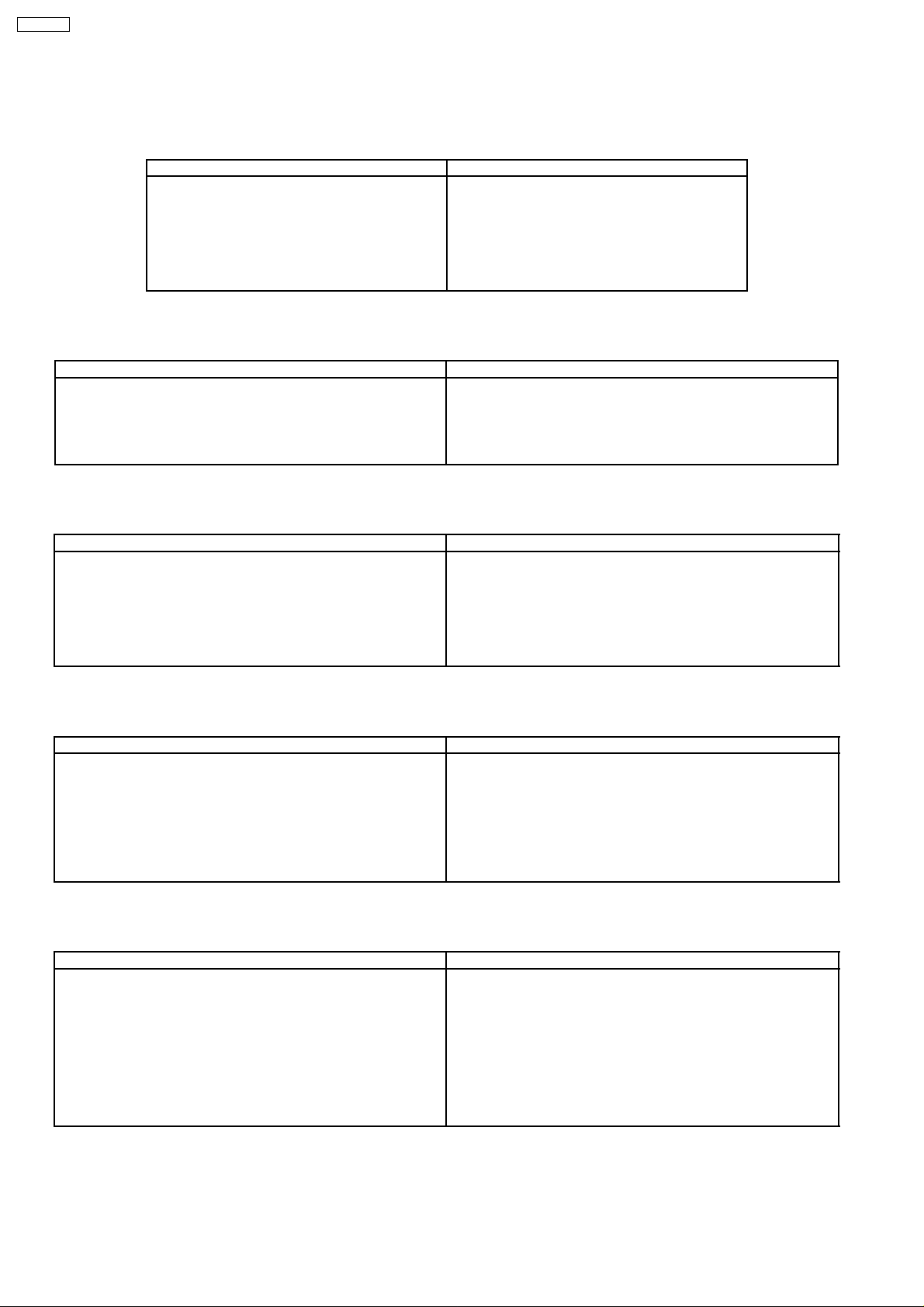
5 ADJUSTMENT PROCEDURE
5.1. B VOLTAGE
Item/Preparation Adjustment Procedure
1. Operate the TV set.
2. Set controls : (MARKET MODE CHK 2)
Bright ............. Minimum
Contrast ......... Minimum
Volume ............. Minimum
5.2. RF AGC
Item/Preparation Adjustment Procedure
1. Receive a colour bar pattern.
2. Set the input level to 66 (+1.2) db.
(75Ω opened)
3. Connect an oscilloscope to AGC : TPA 20 with DC mode.
1. Confirm that the indicated test points for the
specified voltage:
TPA 140 : 141±2V
TPA 12 : 12±1.0V
TPA 9 : 9±1V
TPA 5 & TPA 32 : 5±1V
TPA 220 : 220±15V
1. Set RF AGC Control such as to procedure a snowy picture.
2. Set RF AGC Control at the point just before the voltage at AGC :
TPA 20 begins to drop.
3. Increase the input level by 3 db and confirm that the voltage
changes.
5.3. HIGH VOLTAGE
Item/Preparation Adjustment Procedure
1. Operate the TV set.
2. Receive the crosshatch pattern.
3. Set to 0 Beam
(Screen Control : min. CONTRAST : min)
5.4. SUB TINT
Item/Preparation Adjustment Procedure
1. Receive a 3.58 MHz NTSC rainbow pattern
2. Connect oscilloscope to A21 pin 6.
3. Set controls:
BRT................CENTER
COLOUR........CENTER
CONTRAST....MAX
NTSC TINT.....CENTER
AI....................OFF
5.5. SUB CONTRAST
Item/Preparation Adjustment Procedure
1. Receive a colour bar pattern.
2. Connect an oscilloscope to TPA40.
3. Connect a short jumper between D11-1 and D11-2 / TPA53 and
TPA54 FBT pin 3 or TPA34 and TPA32.
4. Set controls:
Picture menu ........ Dynamic Normal
AI ............................. off
1. Connect a DC voltage meter to D850 cathode and confirm the
voltage is 141.0±2.0V.
2. Connect a high voltage meter (Electrostatic Type) to an anode of
the picture tube.
3. Confirm that the high voltage is within the range of 31.0+0.7V,
-1.5V.
1. Adjust Sub NTSC Tint so that the peak of level of waveform is
similar to Fig. 3
2. Receive the Rainbow pattern (3.58 MHz NTSC) on both of Main
and Sub pictures.
3. Adjust Sub NTSC Tint 2 so that the peak of level of 1.3±0.5V
1. Adjust Bright Colour:
a=2.4±0.2Vp-p
2. Adjust Sub Contrast Colour:
b=2.4±0.1Vp-p
8
5.6. PAL COLOUR OUTPUT
Item/Preparation Adjustment Procedure
1. Receive PAL colour bar pattern.
2. Connect an oscilloscope probe to TPA40.
3. Connect a short jumper to FBT pin 3 or TPA34 and TPA32.
4. Set control :
Picture menu.....................DYNAMIC NORMAL
AI.................................... ..off (for model with AI only)
5.7. NTSC COLOUR OUTPUT
Item/Preparation Adjustment Procedure
1. Apply 3.58MHz NTSC Rainbow pattern.
2. Connect an oscilloscope to TPA40.
3. Connect a short jumper to FBT pin 3 or TPA34 and TPA32.
4. Set control :
Picture menu.......................DYNAMIC CONTROL
Channel Colour Set...........STD
TX-25P80T
1. Adjust Bright Control.
a = 2.3±-0.2Vp-p
2. Adjust Sub Colour control.
3. Connect the osciloscope probe to TPA40.
4. Connect the waveform.
b = 3.1±-0.5Vp-p
1. Adjust Bright Control.
a = 2.3±-0.2Vp-p
2. Connect the waveform.
b = 1.3±-0.5Vp-p
9
 Loading...