

Panasonic TX-25P20T Service Manual
TX-25P20T
MX-8A Chassis
ORDER NO. MT V0005131C3
Colour Television
Specification
Power Source : AC AUTO 110 / 240V, 50/60Hz
Power Consumption : 165W (Max) 0.7W (Stand-by
condition)
Aerial Impedance: 75Ω Coaxial type
Tuning System: Frequency Synthesizer Auto
Search Tuning Pos : 100 Positions
Receiving System : 17 System
Receiving Channels :
VHF 2-12 (PAL/SECAM B,K1) 0-12
(PAL B AUST)1-9 (PAL B N.Z) 1-
12 (PAL/SECAM D) 1-12 (NTSC M
JAPAN) 2-13 (NTSC M U.S.A)
UHF 21-69 (PAL G,H,I/SECAM
G,K,K1)28-69 (PAL B AUST) 13-
57 (PAL D,K)13-62 (NTSC M
JAPAN)14-69 (NTSC M U.S.A)
CATV S1-S20 (OSCAR) 1-125 (U.S.A
CATV) C13-C49 (JAPAN) S21-
S41 (HYPER)Z1-Z37 (CHINA)
Intermediate Frequency :
Video 38.0 MHz
Sound 31.5 MHz (D,K) / 32.5MHz (B,G)
32.0 MHz (I) / 32.5MHz (M)
Colour 33.57 MHz (PAL)33.6 MHz
(SECAM) 34.42 MHz (NTSC)33.75
MHz (SECAM)
Receiving Stereo Sound System AV STEREO / TEXT
Video / Audio Terminals :
AV 1,2,3 IN S-Video Y:1.0V p-p 75Ω DVD IN S-Video C:0.3Vp-p 75Ω
Y/PB/PR (Phone type) Y:1.0 Vp-p 75Ω PB, PR:0.7 Vp-p 75Ω Video 1.0
Vp-p 75Ω Audio Approx. 400mV 47KΩ
Monitor Out : Video 1.0 Vp-p 75ΩAudio Approx,
400mV 1kΩ
High Voltage : 31.0 kV (+0.7, -1.5kV )at zero
beam current
Picture Tube : A60LQK285X Type 25
(60cm)Measured diagonally, 104°
deflection
Audio Output : 16W
Dimensions : Height : 530 mmWidth : 626
mmDepth : 456 mm
Mass : 35.0 kg (Net)
Accessories Supplied Remote Control Transmitter x 1, R6 Battery x 2
Specifications are subject to change without notice. Mass and
dimensions shown are approximate.
© 2001 Matsushita Electric Industrial Co., Ltd. All
rights reserved. Unauthorized copying and
distribution is a violation of law.

TX-25P20T
CONTENTS
Page Page
1 Safety Precautions 3
1.1. General Guide
1.2. Leakage Current Cold Check
1.3. Leakage Current Hot Check
1.4. X-Radiation
2 Location of Controls and Circuit Boards
3 Service Hints
4 Special Service Procedure
4.1. Market Mode Function
5 Adjustments
5.1. White Balance (MARKET MODE CHK 3)
6 G-BOARDTNP4G120AK
6.1. A-BOARDTNP4G104BM
7 H-BOARDTNP4G131AC
8 X-BOARDTNP4G108AQ
9 T-BOARDTNP4G115AC
3
10 L-BOARDT NP4G107A Q
3
11 Schematic Diagram for models TC-15PM10R (MX-7 Chassis)
3
4
4
6
6
7
9
11
13
14
15
12 SCHEMAT IC 1
13 SCHEMAT IC 2
14 SCHEMAT IC 3
14.1. SCHEMATIC 4
14.2. SCHEMATIC 5
14.3. SCHEMATIC 6 (LEFT HALF)
14.4. SCHEMATIC 6 (RIGHT HALF)
14.5. EXPLODED VIEW
15 Replaceme nt Parts List
16
16
17
18
19
20
21
22
23
24
25
26
27
2
TX-25P20T
1 Safety Precautions
1.1. General Guide
1. It is advisable to insert an isolation transformer in the AC supply before servicing this hot chassis.
Fig. 1
2. When servicing, observe the original lead dress, especially the lead dress in the high voltage circuits. If a short circuit is found,
replace all parts which have been overheated or damaged by the short circuit.
3. After servicing, see to it that all the protective devices such as insulation barriers, insulation papers, shields, and isolation R-C
combinations, are properly installed.
4. When the receiver is not to be used for a long period of time, unplug the power cord from the AC cord outlet.
5. Potential, as high as
involves the danger of a shock hazard from the receiver power supply. Servicing should not be attempted by anyone who is not
thoroughly familiar with the precautions necessary when working on high voltage equipment. Always discharge the anode of the
picture tube to the receiver chassis before handling the tube. After servicing make the following leakage current checks to
prevent the customer from being exposed to shock hazards.
31.7
kV. is present when this receiver is in operation. Operation of the receiver without the rear cover
1.2. Leakage Current Cold Check
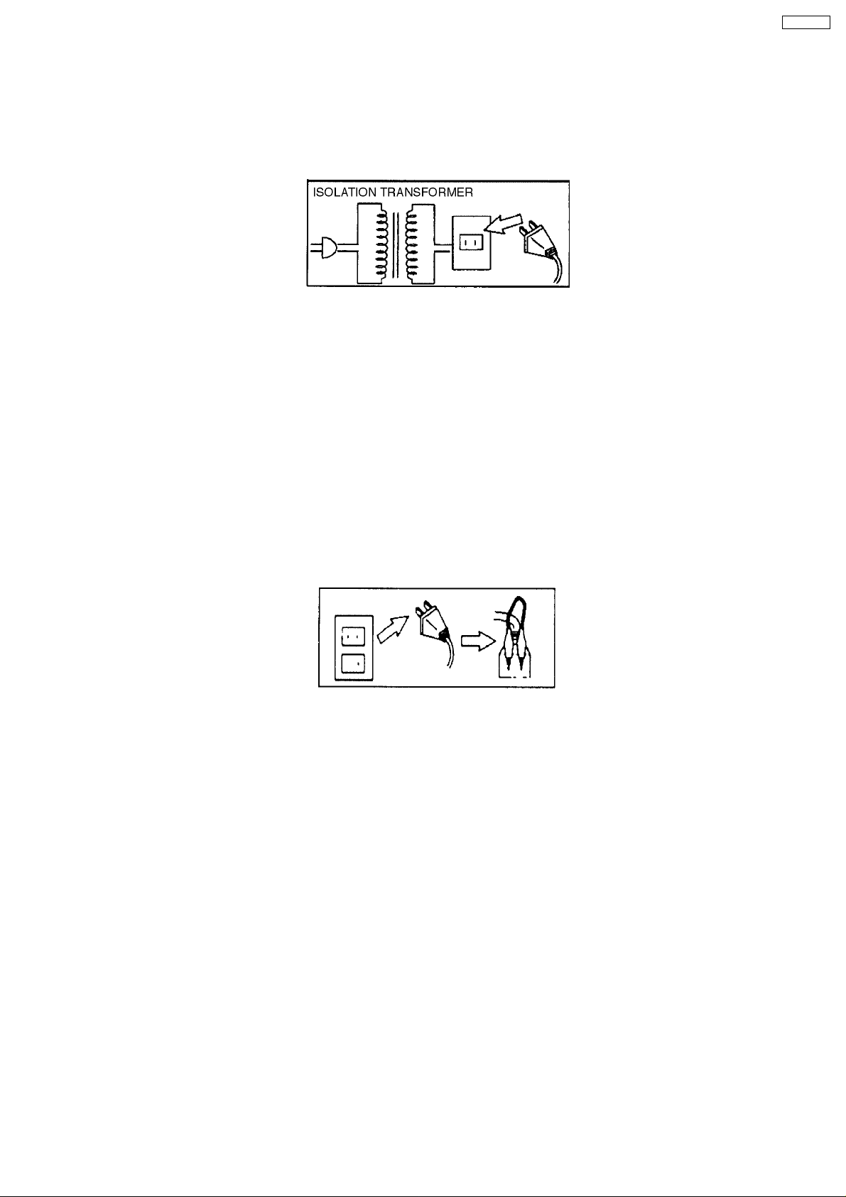
1. Unplug the AC cord and connect a jumper between the two prongs on the plug. Fig. 2.
Fig. 2
2. Turn on the receiver’s power switch.
3. Measure the resistance value, with an ohmmeter, between the jumper AC plug and each exposed metallic cabinet part on the
receiver, such as screw heads, aerials, connectors, control shafts, etc. When the expose d metalli c part has a return path to the
4M
and 20 M
chassis, the reading should be between
the reading must be zero.
ΩΩΩΩ
ΩΩΩΩ
. When the exposed metal does not have a return path to the chassis,
1.3. Leakage Current Hot Check
1. Plug the AC cord directly into the AC outlet.
Do not use an isolation transformer for this check.
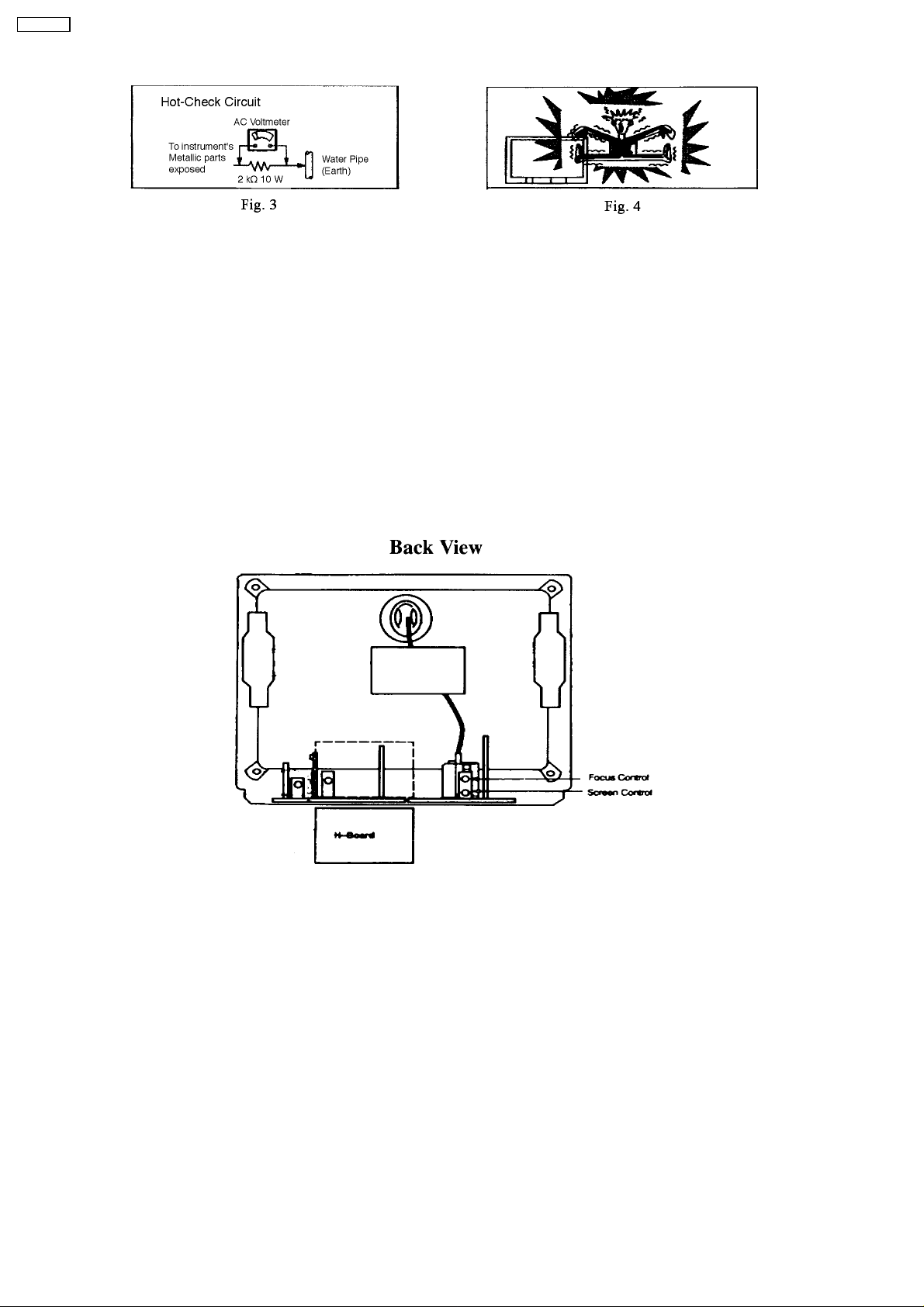
2. Connect a 2kΩ, 10W resistor, in series with an exposed metallic part on the receiver and an earth such as a water pipe.
3. Use an AC voltmeter, with high impedance type, to measure the potential across the resistor.
4. Check each exposed metallic part, and measure the voltage at each point. Fig. 3.
5. Reverse the AC plug in the AC outlet and repeat each of the above measurements.
6. The potential at any point should not exceed
In the case of a measurement being outside of these limits specified, there is a possibility of a shock hazard, and the receiver
should be repaired and rechecked before it is returned to the customer. Fig. 4.
1.0V rms
.
3
TX-25P20T
1.4. X-Radiation
Warning :
1. The potential sources of X-Radiation in TV sets are the High Voltage section and the picture tube.
2. When using a picture tube test rig for service, ensure that the rig is capable of handling
Note: It is important to use an accurate periodically calibrated high voltage meter.
1. Set brightness to minimum.
2. Measure the High Voltage. The meter reading should indicate
immediate service and correction is required to prevent the possibility of premature component failure.
3. To prevent possibility of X-Radiation, it is essential to use the specified picture tube.
31.0 +0.7, -1.5 kV
31.7kV
. If the meter indication is out of tolerance,
without causing X-Radiation.
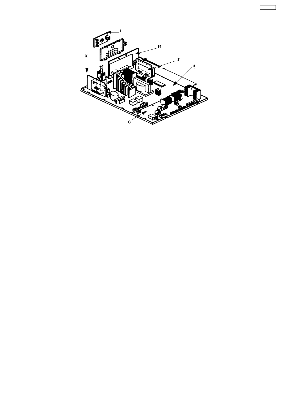
2 Location of Controls and Circuit Boards
Location and Function Name of Circuit Board
A - Main
T - Text
H - Rear Av
L - Crt Board
X - Pin Cushion
G - Power Board
4
TX-25P20T
5
TX-25P20T
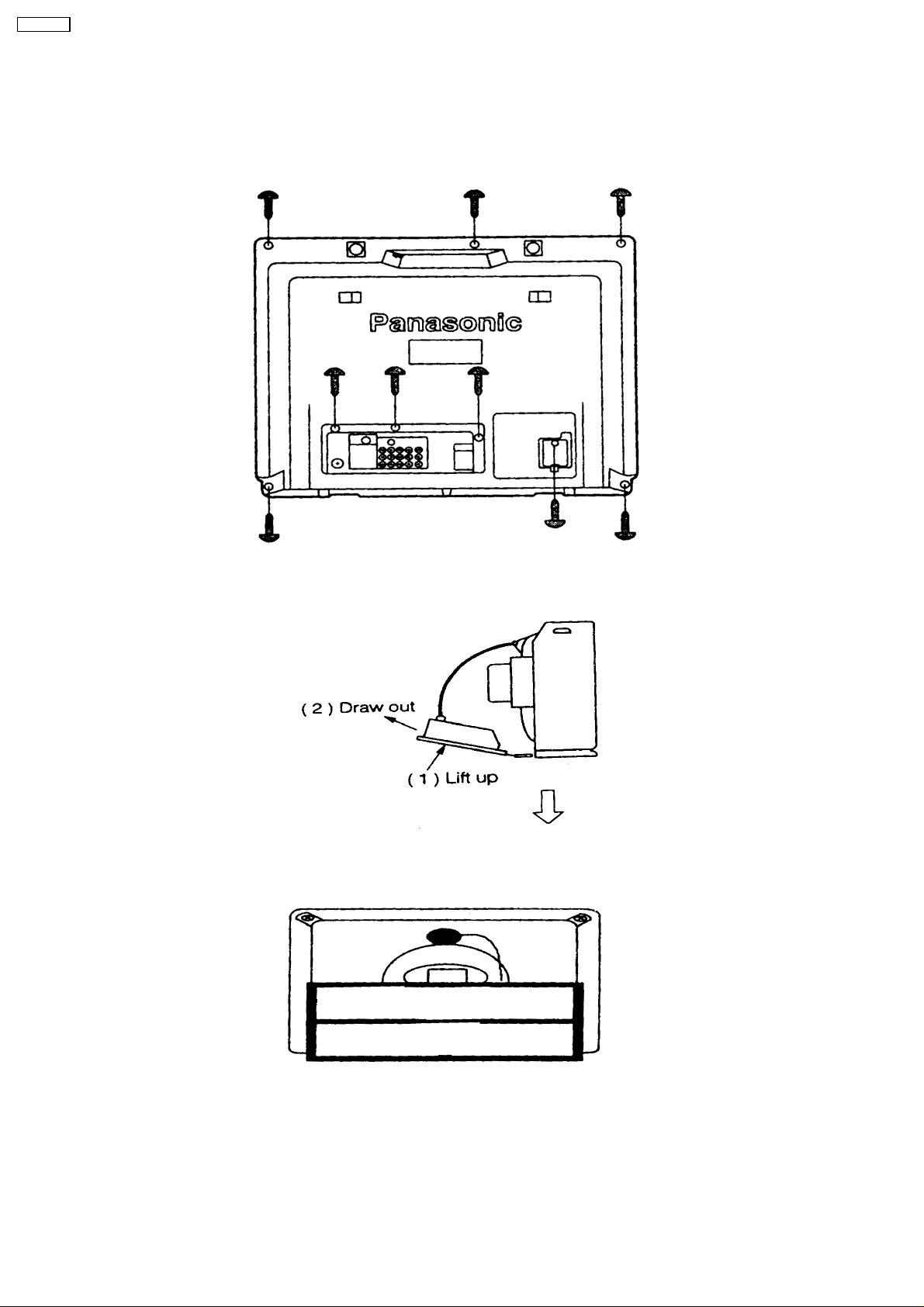
3 Service Hints
How to move chassis into service position
1. Remove 9 screws
2. Draw out Main Chassis
3. Stand the Main Chassis
4 Special Service Procedure
Self Check Function
1.
SELF CHECK is used to automatically check the Bus Lines and Option code of the TV set. Contents of the SELF CHECK are
as follows:
6
a. Confirmation result for IC function.
b. Option code.
Procedure
a. Simultaneously push the OFF TIMER button on the remote control and the Volume Down button - on the TV set panel.
b. The TV enters the selfcheck mode and the result is displayed on the screen (as shown below). Please note that the
programme number will be changed to position “1”.
c. Press any key to clear the selfcheck mode and return to the normal state.
2. How to replace memory IC (1102)
Much data for controlling circuits in the TV set is memorized in the Memory IC (IC1102).
a. Change the defective memory IC to the replacement IC.
b. Turn the TV set ON and perform the SELF CHECK Function.
c. When exiting SELF CHECK Mode the customer settings will return to factory setup.
d. Confirm the correct Deflection and White Balance adjustment.
4.1. Market Mode Function
Outline : MPU controls the functions switching for each IC through IIC bus in this chassis. The
following settings and adjustments can be adjusted by remote control in Market Mode.
1. Selection of Market Mode
Adjust VOLUME to “zero” and set OFF TIMER Button (turn on the timer).
Then simultaneously press the RECALL Button on the remote control and the VOLUME DOWN Button on the TV set.
2. Selection of CHK Mode
Cursor moves to each CHK mode by pressing “1” or “2” of 10 key buttons on the remote control.
TX-25P20T
1. Option Code Setting Mode (CHK 1)
If the memory IC (IC1102) is replaced, option code should be re-memorized.
Option code can be changed by pressing Volume “+” or “-” button.
To memorize, press “0” of 10 key buttons. Fig. A.
Display Adj. Range
Colour sys
Ch. Plan
Noise Mute
Speed
Vcr / Game
Av
Stereo
Geo
Saso
Text
Pana Display
0~6
0~9
Off / On
Off / On
Off / On
Off / On
Off / On
0~2
Off / On
0~2
Off / On
2. VCJ Adjustment Mode
To change the screen (item) in CHK mode, press “3” or “4” of 10 key buttons. Then Data and Level changes by pressing Volume
“+” or “-” button.
Display Adj. Range
RF AGC
BELL FILTER
BY
RY
SHARPNESS
SUB Y CONTRAST
CONTRAST
SUB-BRIGHT
BRIGHT
SUB NTSC TINT
NTSC-TINT
SUB COLOUR
COLOUR
00H ~ FFH
00H ~ 03H
00H ~ 0FH
00H ~ 0FH
0~63
00H ~ 1FH
0~63
00H ~ FFH
0~63
00H ~ 3FH
00H ~ 3FH
00H ~ 3FH
0~63
3. Pincushion Adjustment Mode
To change the screen (item) in CHK mode, press “3” or “4” of 10 key buttons. Then Data and Level changes by pressing Volume
“+” or “-” button.
7
TX-25P20T
Display Adj. Range
PARABOLA
V-HEIGHT (60Hz)
V-HEIGHT (50Hz)
V-CENTER
50 H.CENTER
EW CORNER 2
EW CORNER 1
TRAPEZOID
V-LINEAR
60Hz VS CORRECT
50Hz VS CORRECT
H-WIDTH
00H ~ 3FH
00H ~ 7FH
00H ~ 7FH
00H ~ 07H
00H ~ 1FH
00H ~ 0FH
00H ~ 0FH
00H ~ 3FH
00H ~ 3FH
00H ~ 3FH
00H ~ 3FH
00H ~ 3FH
Note: Picture will be changed to the one horizontal line by pressing “5” of 10 key buttons on the remote control (no. 1-5)
4. White Balance Adjustment Mode
To change the screen (item) in CHK mode, press “3” or “4” of 10 key buttons. Then Data and Level changes by pressing Volume
“+” or “-” button.
Display Adj. Range
B.DR
R.DR
SUB.BR
BRIGHT
B-CUT
G-CUT
R-CUT
00H ~ FFH
00H ~ FFH
00H ~ FFH
0~63
00H ~ FFH
00H ~ FFH
00H ~ FFH
8
5 Adjustments
Item / Preparation Adjustment Procedure
B Voltage
1. Operate the TV set.
2. Set control: (MARKET MODE CHK 2)
Brightness.............minimum
Sub Bright.............minimum
Volume.................minimum
RF AGC
1. Receive a colour bar pattern.
2. Set the input level to 63 ± 1dB. (75Ω opened).
3. Connect an oscilloscope to AGC:TPA20 with DC mode.
High Voltage
1. Operate the TV set.
2. Receive the crosshatch pattern.
3. Set to 0 Beam.
(Screen Control : min. CONTRAST : min)
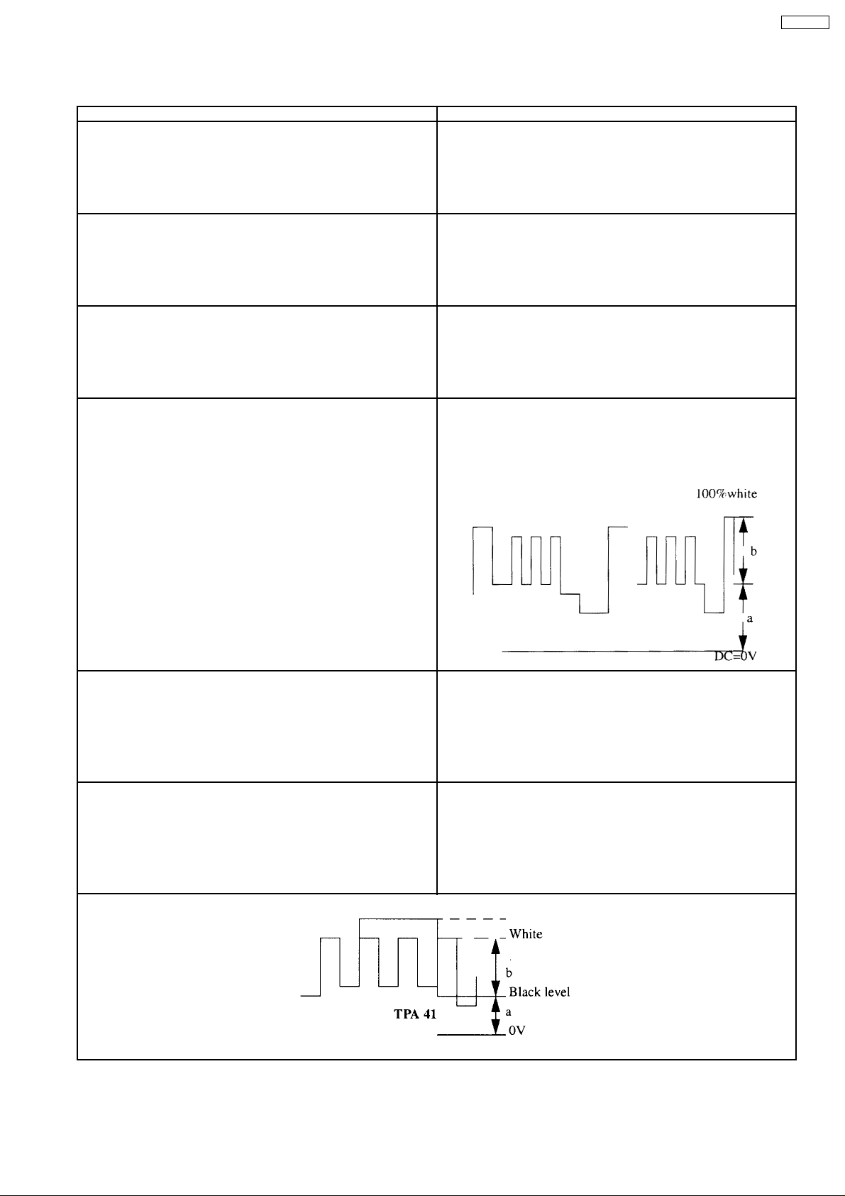
Sub Contrast
1. Receive a colour bar pattern.
2. Connect an oscilloscope to TPA41.
3. Connect a short jumper between TPA57 & TPA50 FBT pin3 &
TPA32.
4. Set controls:
Picture menu....................Dynamic Normal
Confirm the indicated test points for the specified voltage:
TPA 140 : 140 ± 0.2V
TPA 12 : 12 ± 1V
TPA9:9±1V
TPA 5 & TPA 32 : 5 ± 1V
TPA 220 : 220 ± 15V
1. Set RF AGC Control such as to procedure a snowy picture.
2. Set RF AGC Control at the point just before the voltage at
AGC:TPA20 begins to drop.
3. Increase the input level by 2dB and confirm that the voltage
changes.
1. Connect a DC voltage meter to TPD 16 and confirm the +B voltage
is 141.0 ± 2.0V.
2. Connect a high voltage meter (Electrostatic Type) to an anode of
the picture tube.
3. Confirm that the high voltage is within the range of 31.0 ± 0.7 kV.
1. Adjust Bright Control:
a=2.3 ± 0.2 Vp-p
2. Adjust Sub Contrast Control:
b=2.8 ± 0.1 Vp-p
TX-25P20T
PAL Colour Output
1. Receive a PAL colour bar pattern.
2. Connect an oscilloscope probe to TPA41.
3. Connect a short jumper between TPA57 & TPA50 FBT pin3 &
TPA32.
4. Set controls:
Picture menu....................DYNAMIC NORMAL
NTSC Colour Output
1. Apply 3.58MHz NTSC Rainbow pattern.
2. Connect an oscilloscope probe to TPA40.
3. Connect a short jumper between D11-1 and D11-2 / TPA53 and
TPA54.
4. Set controls:
Picture menu....................DYNAMIC NORMAL
1. Adjust Bright Control:
a=2.3 ± 0.2 V
2. Adjust Sub Colour control.
3. Connect the oscilloscope probe to TPA41.
4. Connect the waveform:
b=2.2 ± 0.1 Vp-p
1. Adjust Bright Control:
a=2.3 ± 0.2 V
2. Confirm that the waveform:
b=1.3 ± 0.5Vp-p
p-p
9
TX-25P20T
Before Colour Purity, Convergence and White Balance adjustments are attempted, V.
Center, V. Height, H. Width, H. Centre and Focus adjustments must be completed.
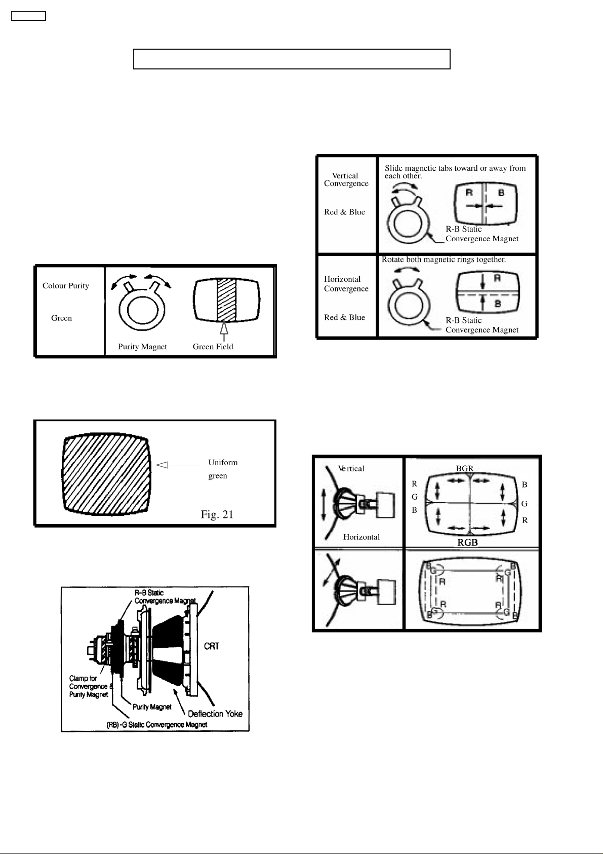
Colour Purity
1. Set the Brightness and Contrast controls to their maximum
positions.
2. Operate the TV set for over 15 minutes.
3. Fully degauss the picture tube by using an external
degaussing coil by rotating R-B static convergence magnet.
4. Apply a crosshatch pattern signal and adjust the static
convergence magnets roughly.
5. Apply a green pattern signal.
6. Loosen a clamp screw for the deflection yoke and move the
deflection yoke as close to the purity magnet as possible.
7. Adjust the purity magnetic so that a vertical green field is
obtained at the centre of the screen.
Fig. 20
8. Slowly press the deflection yoke and set it where a uniform
green field is obtained.
Convergence
1. Apply a crosshatch pattern signal and set Contrast control
to the maximum position.
2. Adjust Brightness control to obtain a clear pattern.
3. Adjust the Red and Blue line at the centre of the screen.
Fig. 22
4. Adjust Red and Blue with Green line at centre of the screen
by rotating (RB) -G static convergence magnet.
5. Lock convergence magnets with silicone sealer.
6. Remove the DY wedges and slightly tilt the deflection yoke
vertically and horizontally to obtain the good overall
convergence.
9. Adjust roughly the Low Light controls and make sure that a
uniform white field is obtained.
10. Tighten the clamp screw.
Fig. 23
7. Fix the deflection yoke by reinserting the DY wedges. Refer
to Fig. 24.
8. If purity error is found, repeat “Colour Purity” adjustment.
10
5.1. White Balance (MARKET MODE CHK 3)
TX-25P20T
5.1.1. Preparation
1. Receive a colour bar signal with colour “OFF”, and operate
the TV set for more than 15 minutes.
2. Set the picture menu to “DYNAMIC NORMAL” and the AI to
off.
3. Connect an oscilloscope to TPL7 with DC mode.
4. Set the TV set to Market Mode : white balance adjustment
(CHK 3).
5. Set the data level of SUB BRIGHT, R,G,B-CUT OFF and
R,G,B-DRIV to the table values.
Display Data Level
R-CUT OFF 63
G-CUT OFF 128
B-CUT OFF 63
R-DRIVE 128
B-DRIVE 128
SUB BRIGHT 63
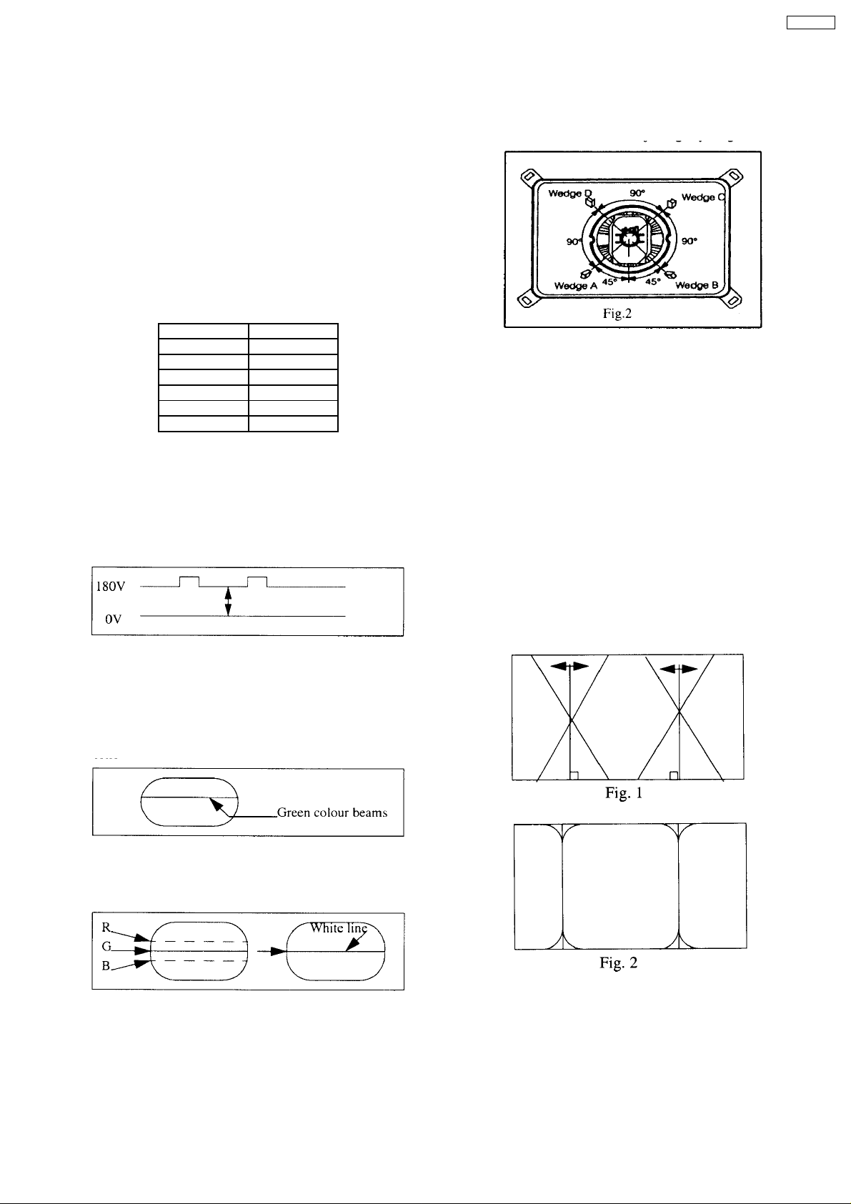
5.1.2. Adjustment
1. Select G-CUT OFF adjustment mode and collapse vertical
scan.
2. Adjust G-CUT OFF control to become the DC=0V to video
level at 180 V as shown in Fig. 1.
Note : Write down the original value for each address
before adjusting anything.
8. Wedge A shown in Fig. 2 should be fixed within a range of
45 to the left of the vertical line as shown.
9. After inserting wedge A, insert wedges B, C and D. The
wedges should be set 90 degrees apart from each other.
10. Be certain that the four wedges are firmly fixed and the
Deflection Yoke is tightly clamped in place otherwise the
Deflection Yoke may shift its position and cause a loss of
convergence and purity.
5.1.3. Adjustment of Pincushion
1. Receive the crosshatch pattern.
2. Adjust the vertical line to straight line by PARABOLA.
3. Adjust the vertical line to straight line of bothside vertical
line in Fig. 1 by TRAPEZOID.
4. Adjust the corner-pincushion in Fig. 2 by EW-CORNER 1
and EW-CORNER 2.
3. Slowly turn the screen control clockwise until a green colour
horizontal line appears on the picture tube. This is the
setting point for the screen control.
Note that do not adjust the G-CUT OFF setting in the
following procedure.
4. Adjust the remained R and B-CUT OFF contyrols so as to
get a white horizontal line on the screen.
5. Return to full SCAN by pushing the position 5 key on the
remote control.
6. Adjust the R-Drive and B-Drive controls as to obtain uniform
white on the white bar of the grey scale pattern.
7. Confirm correct B/W rendition and greyscale tracking or
repeat CUT OFF and drive control set up.
11
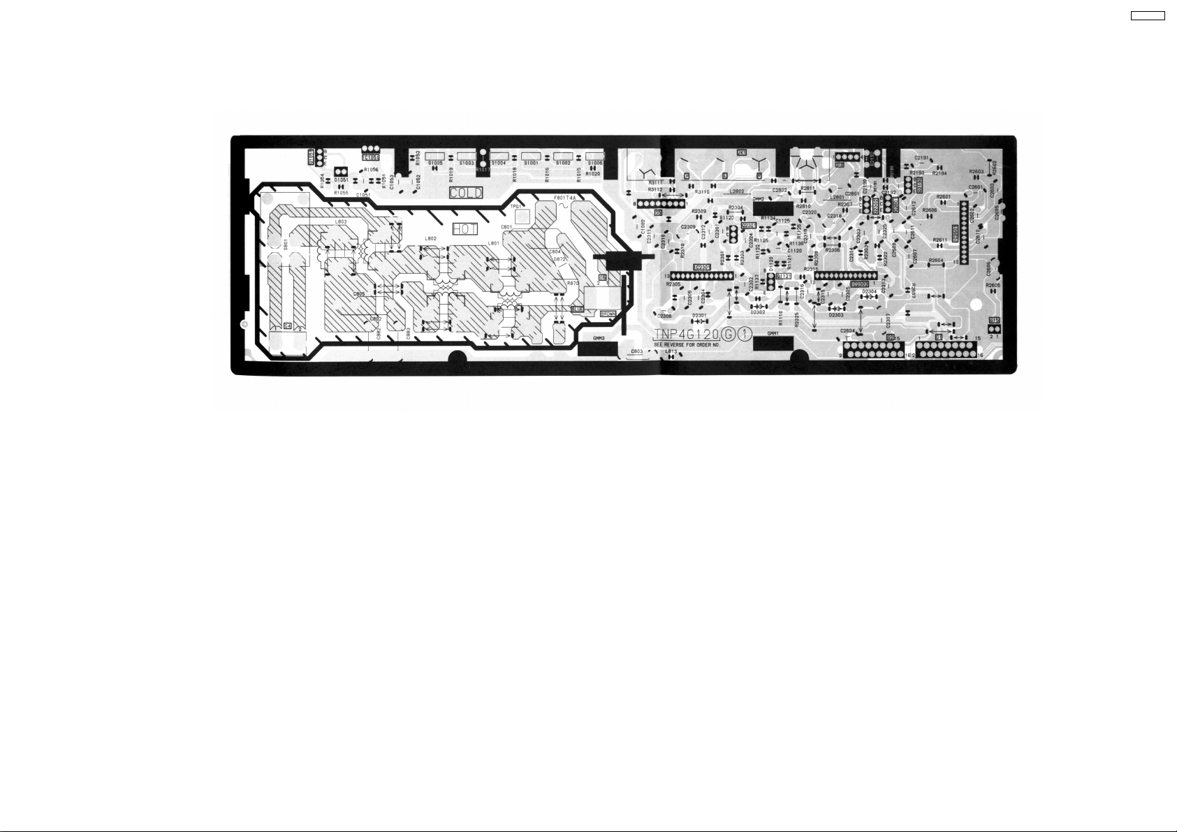
6 G-BOARD
TNP4G120AK
TX-25P20T
13
TX-25P20T
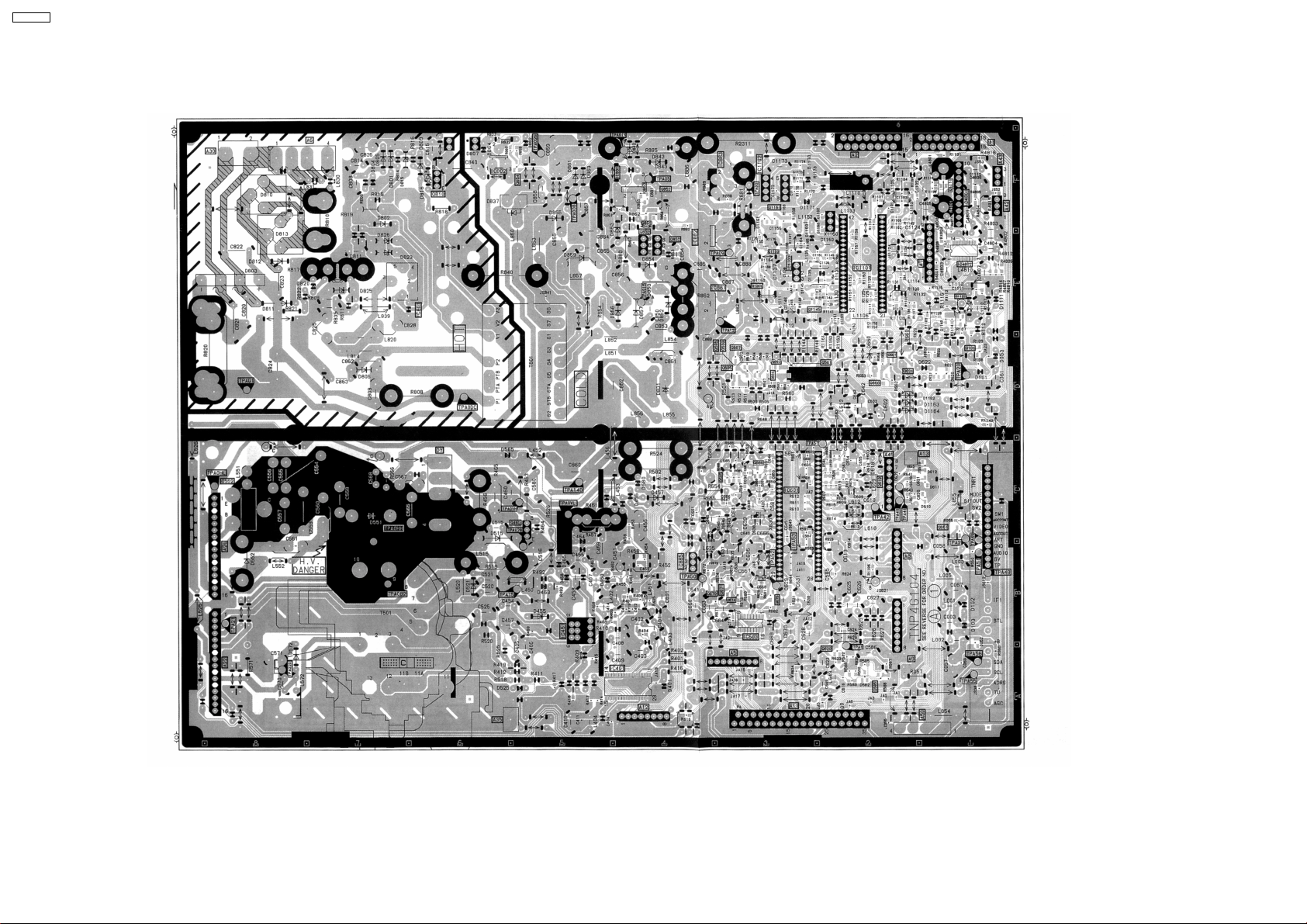
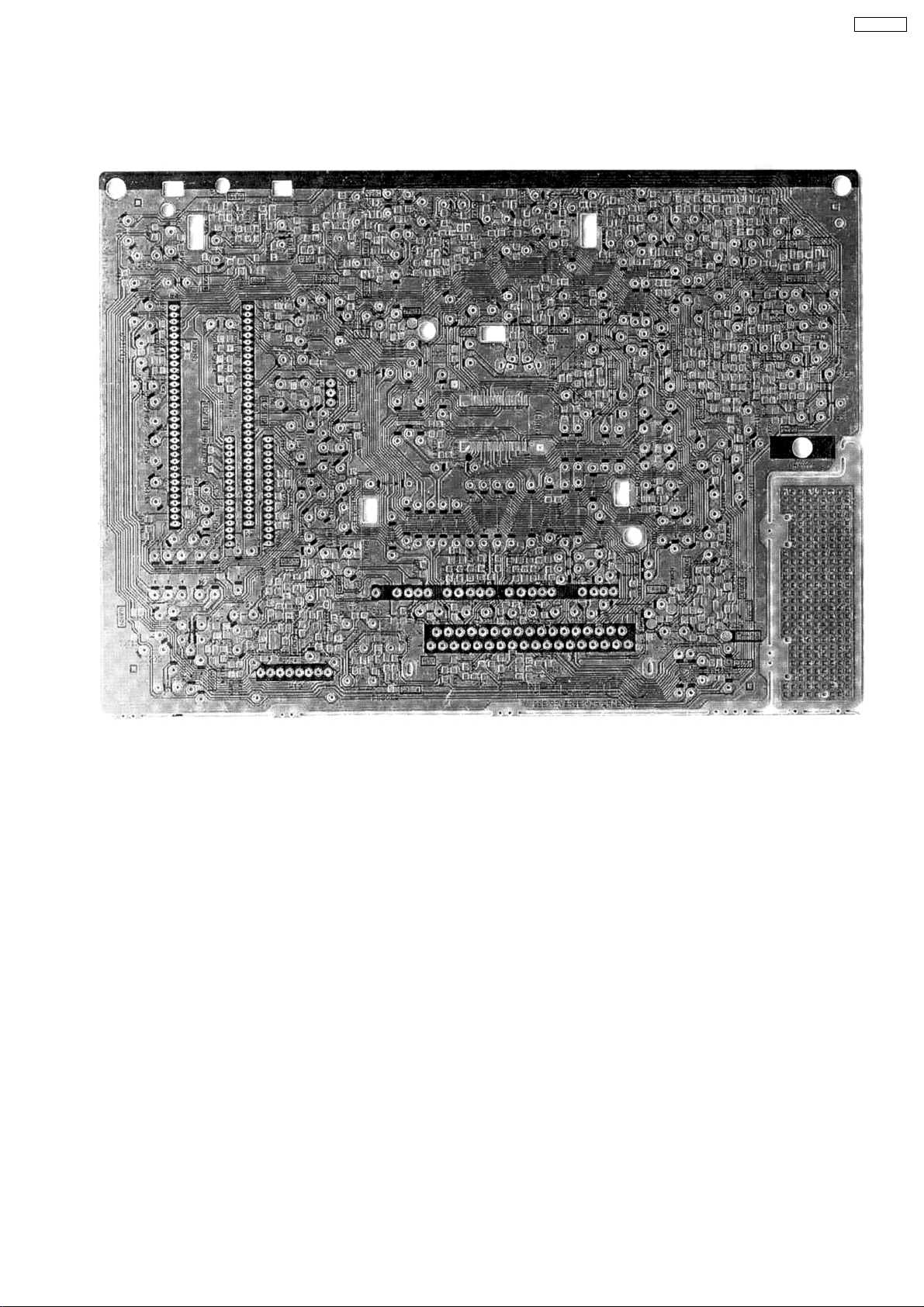
6.1. A-BOARD
TNP4G104BM
14
7 H-BOARD
TNP4G131AC
TX-25P20T
15
 Loading...