

Panasonic TX-23LX50A User Manual
STILL
ASPECT
SURROUND
N
R-TUNE
OK
MENU
TV/AV
TV/TEXT
HOLD
1 2 3
4 5 6
7 8 9
REC
F.P. INDEX
0
VCR DVD
TV
Operating Instructions
LCD TV
Model No.
TX-23LX50A
The illustration shown is an image.
Please read these instructions before operating your set and retain them for future reference.
English
TQBC2012-1
Dear Panasonic Customer
Welcome to the Panasonic family of customers. We hope that you will have
many years of enjoyment from your new LCD TV.
To obtain maximum benefit from your set, please read these Instructions before
making any adjustments, and retain them for future reference.
Retain your purchase receipt also, and note down the model number and serial
number of your set in the space provided on the back cover of these instructions.
Contents
Accessories ............................................................... 2
Warnings and Precautions ........................................ 3
Fitting remote control batteries ................................. 5
How to use the LCD stand ........................................ 5
How to hang the LCD TV on the wall ........................ 6
Antenna connection .................................................. 6
Audio / Video connections......................................... 7
How to connect the Headphones terminal ............. 7
To bundle the cables with the clamper .................. 7
How to connect the Monitor Output
terminals to other Equipment ...................... 8
How to connect the AV1 Input terminals ................ 8
How to connect the DVD Input terminals ............... 8
Basic controls: top panel and remote control ............ 9
Power On / Off ........................................................ 10
Using the On Screen Displays ................................ 10
Tuning ......................................................................11
Accessories
Tuning menu ......................................................... 11
Auto tuning .......................................................... 12
Auto tuning (via top panel) ................................... 12
Manual tuning ...................................................... 13
Manual tuning (via top panel) .............................. 13
Picture menu ........................................................... 14
Sound menu ............................................................ 15
Setup menu ............................................................. 16
Aspect Controls ....................................................... 17
Teletext operation .................................................... 18
VCR / DVD operation .............................................. 20
Stereo / Bilingual Sound Selection .......................... 21
Remote control setting ............................................ 21
Troubleshooting ...................................................... 22
Maintenance ........................................................... 22
Specifications .......................................................... 23
WARRANTY............................................... back cover
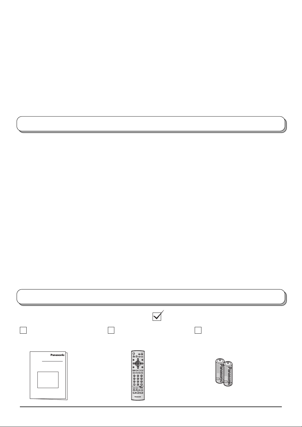
Check that you have the accessories and items shown
Operating Instruction
book
Remote Control
Transmitter
(N2QAJB000121)
STILL
ASPECT
SURROUND
R-TUNE
N
OK
MENU
TV/AV
F.P. INDEX
TV/TEXT
HOLD
1 2 3
4 5 6
7 8 9
0
VCR DVD
REC
TV
2
Batteries for
the Remote
Control Transmitter
(2 × R6 (AA) size)
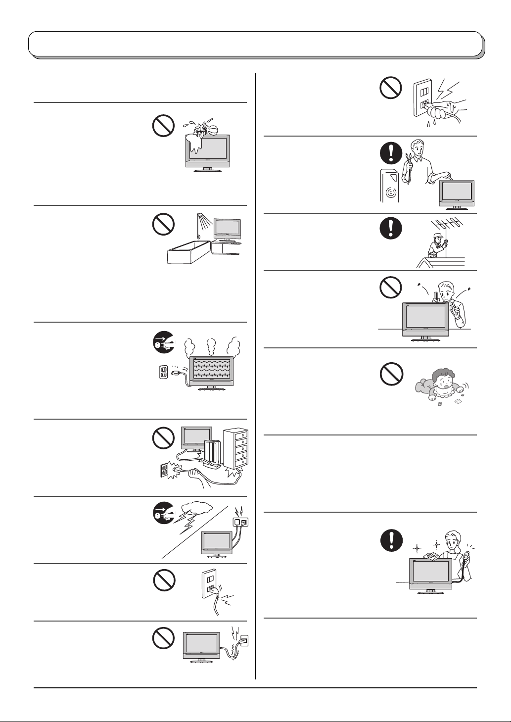
Warnings and Precautions
• This TV set is designed to operate on AC 110-240 V,
50 / 60 Hz.
• To prevent damage which
might result in electric shock
or fire, do not expose this TV
set to rain or excessive
moisture. This TV must not
be exposed to dripping or
splashing water, and objects
filled with liquid, such as vases, must not be placed
on top of or above the TV.
• DO NOT use this unit near
water. (Near a bath tub, etc.)
Refer all servicing to
qualified service personnel.
Servicing is required when
the apparatus has been
damaged in any way, such as power-supply cord or
plug is damaged, liquid has been spilled or objects
have fallen into the apparatus, the apparatus has been
exposed to rain or moisture, does not operate normally,
or has been dropped.
•
Unplug the power cord in the
event of any malfunction
(screen goes blank, no
sound, odd sounds, smoke or
unusual odours coming from
the unit).
Unplug the power cord if
foreign matter or water falls into the unit, or if the unit
is dropped or the cabinet is damaged.
• TAKE CARE NOT to
damage the power cord.
• DO NOT touch the aerial
cable and this unit when
there is lightning.
• DO NOT use if the power
cord or power plug is
damaged, or if the plug does
not fit tightly into the socket.
• DO NOT touch the power
plug if your hands are wet.
• Turn the power “Off”
before connecting other
electrical equipment.
• Ask your sales outlet to
install the aerial.
•
WARNING : HIGH VOLTAGE!!!
Do not remove the rear
cover as live parts are
accessible when it is
removed. There are no user
serviceable parts inside.
• WARNING
Keep unneeded small parts
and other objects out of the
reach of small children.
These objects can be
accidentally swallowed.
Also, be careful about packaging materials and plastic
sheets.
• Refer all servicing to qualified service personnel.
Servicing is required when the apparatus has been
damaged in any way, such as power-supply cord or
plug is damaged, liquid has been spilled or objects
have fallen into the apparatus, the apparatus has been
exposed to rain or moisture, does not operate normally,
or has been dropped.
• Cabinet and LCD panel care
Remove the mains plug
from the wall socket. The
cabinet and LCD panel
can be cleaned with a soft
cloth moistened with mild
detergent and water.
Do not use solutions
containing benzol or petroleum.
• DO NOT use at a voltage
other than indicated.
• When ambient temperature is cool, the picture may
take a short time to reach normal brightness, but this
is not a malfunction. (After brief moment, the picture
will have normal brightness.)
3
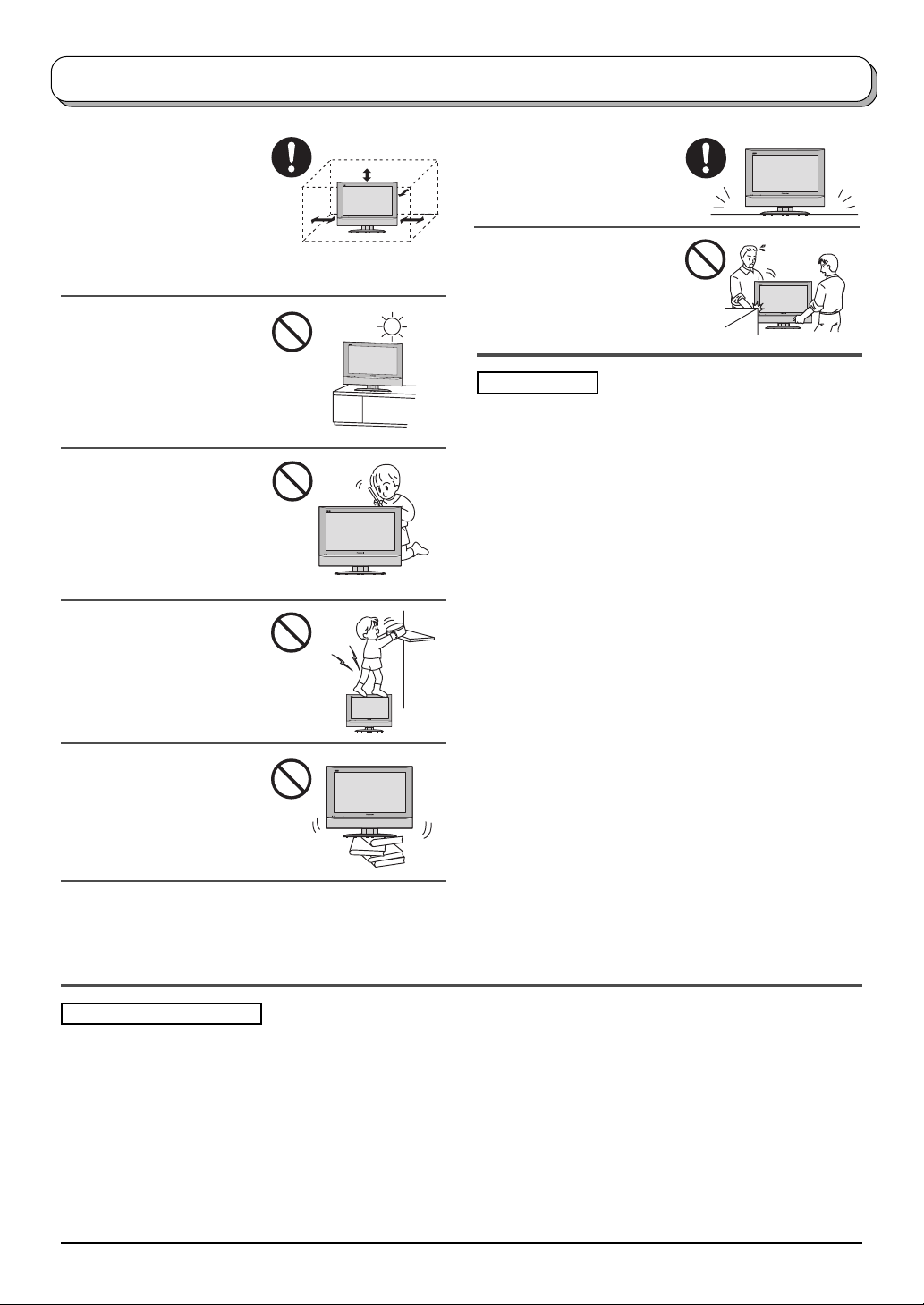
Warnings and Precautions
• Adequate ventilation is
essential to prevent failure
of electrical components,
we recommend that a gap
of at least 10cm is left all
around this TV set even
when it is placed inside a
cabinet or between shelves.
• Avoid exposing the TV set
to direct sunlight and other
sources of heat. To
prevent fire, never place
any type of candle or
naked flame on top or
near the TV set.
• DO NOT insert foreign
objects (metal or easily
flammable objects).
• DO NOT stand, or place
heavy objects on the unit.
Particular care should be
taken by families with
small children.
• DO NOT place in an
unstable location.
• Place in a safe location.
• DO NOT jolt the unit.
Preparation
• Receiver Location
Locate for comfortable viewing. Avoid placing where
sunlight or other bright light (including reflections) will
fall on the screen.
Use of some types of fluorescent lighting can reduce
remote control transmitter range.
Adequate ventilation is essential to prevent internal
component failure. Keep away from areas of excessive
heat or moisture.
To insure optimum picture do not position magnetic
equipment (motors, fans, other speakers, etc.) nearby.
• Optional External Equipment
The Audio / Video connection between components
can be made with shielded video and audio cables.
For best performance, we recommend 75 Ω coaxial
aerial cable is used. Cables are available from your
dealer or electronic supply store.
Before you purchase any cables, be sure you know
what type of output and input connectors your various
components require. Also determine the length of cable
you will need.
• For optimum quality picture
When the LCD is exposed to light from outdoors or
lighting fixtures, high-contrast pictures may not be
displayed clearly. Turn off florescent lamps near the
LCD and place in a location not exposed to outdoor
light.
Pixel Statement (LCD)
An image on an LCD panel is created by many dots known as pixels. The more pixels on the panel, the more
detailed image can be displayed. To create a colour image each pixel is made up of three tiny coloured dots (1 each
of red, green and blue). This gives a total far in excess of one million individual dots manufactured into the panel.
Each one of these dots is precisely controlled by the electronics of the TV to produce the picture.
Whilst Panasonic maintains the highest standards in manufacturing technology and processes in the construction
of these panels, there are a number of allowable Pixel/Dot failures that would still allow the panel to be defined as
a good panel. It is not possible to guarantee absolutely no pixel loss.
4
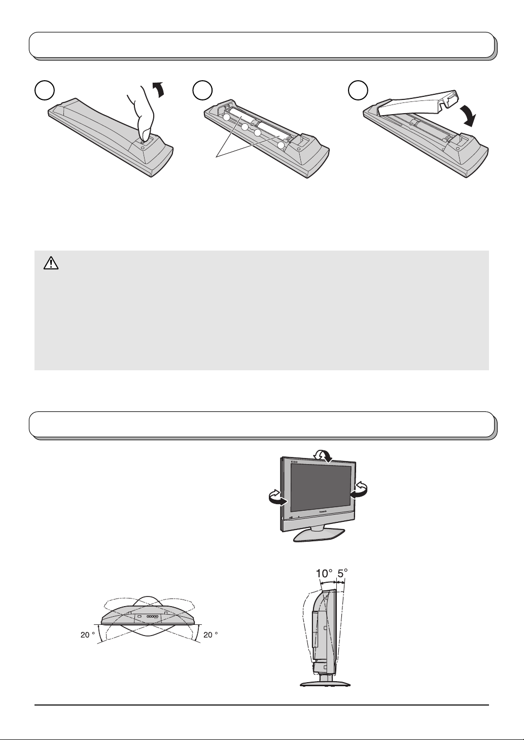
Fitting remote control batteries
1 2 3
+
-
+
“R6 (AA)” size
Pull and hold the hook, then
open the battery cover.
Do not use rechargeable (Ni-Cad) batteries.
They are different in shape and performance and may fail to ensure correct operation.
Insert batteries - note correct
polarity ( + and
-
).
Replace the cover.
Battery cautions
The incorrect use of batteries can cause electrolyte leakage which will corrode the Remote Control or cause
the batteries to burst.
Observe the following precaution:
1. Batteries shall always be replaced as a pair. Always use new batteries when replacing the old set.
2. Do not combine a used battery with a new one.
3. Do not mix battery types (example:“Zinc Carbon” with “Alkaline”).
4. Do not attempt to charge, short-circuit, disassemble, heat or burn used batteries.
5. Battery replacement is necessary when remote control acts sporadically or stops operating the TV set.
How to use the LCD stand
Adjust the LCD panel to your desired angle.
The LCD panel can be adjusted the following direction:
5 ° Forward
10° Backward
20° Right
20° Left
(View from the top)
POWER TV/VIDEO – VOL + CH
(View from the side)
5
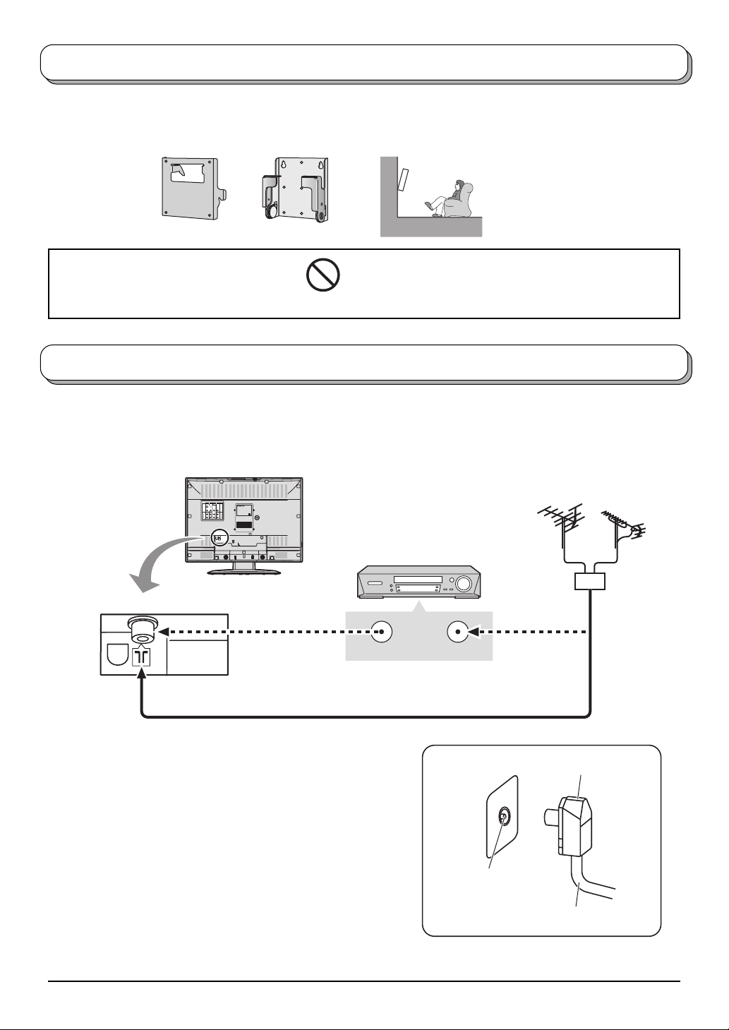
How to hang the LCD TV on the wall
This LCD TV is for use only with the following optional accessory.
Wall-hanging bracket ........................................................ TY-WK22LR1W
•
Always be sure to ask a
qualified technician to carry
out set-up.
WARNING
• DO NOT use other optional accessories.
Use with any other type of optional accessories may cause instability which could result in the possibility of injury.
Antenna connection
For proper reception of VHF / UHF channels, an external antenna is required. For best reception, an outdoor
antenna is recommended.
Back of the TV
MONITOR OUTAV1 IN AV2 IN
COMPONENT
S-VIDEO
VIDEO VIDEO
L/MONO
AUDIO
R
LCD TV
Model No. :
TX-23LX50*
Power Rating : AC Auto 110-240V 〜 50/60 Hz Max.Amps. : 1.65A
Y
Matsushita Electric Industrial Co., Ltd.
Made in Japan
B/CB
P
L
PR/CR
AUDIO
R
DO NOT REMOVE COVER,
NO USER-SERVICEABLE PARTS INSIDE.
REFER SERVICING TO QUALIFIED
Though surface of the unit may feel
warm during operation, this condition
is definitely normal.
>PS< TBMF***
75 Ω Coaxial cable
Notes:
• Additional equipment, cables and adapter plugs shown are not
supplied with this TV set.
• To obtain optimum quality picture and sound, an Aerial, the
correct cable (75 Ω coaxial) and the correct terminating plug are
required.
• If a communal Aerial system is used, you may require the correct
connection cable and plug between the wall Aerial socket and
your TV.
• Your local Television Service Centre or Dealer may be able to
assist you in obtaining the correct Aerial system for your particular
area and the accessories required.
• Any matters regarding Aerial installation, upgrading of existing
systems or accessories required, and the costs incurred, are
the responsibility of you, the Customer.
VCR
ANT INPUTANT OUTPUT
RF in terminal
VHF Aerial UHF Aerial
Mixer
OR
Coaxial Aerial plug
75 Ω Coaxial cable
6
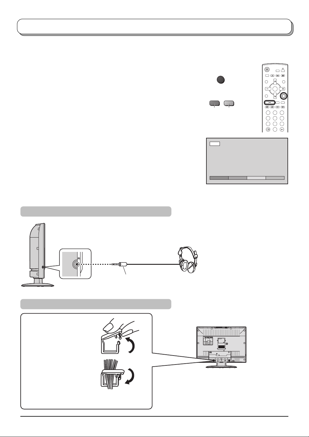
Audio / Video connections
It is possible to connect a variety of additional equipment to this TV. The following pages detail how to connect
external equipment to the rear of the TV.
Once your equipment is connected, use the following procedure to view the input:
Press the TV/AV button.
Whilst the on screen selector keys are displayed, press coloured buttons
to select the AV source you wish to view.
Red button : AV1
Green button : AV2
The on screen selector keys that appear clear after a few seconds. If you
want to select an input when the keys are not shown, press any coloured
button and the keys will reappear.
Notes:
• You can also select an AV source using the TV/AV button on the
top panel of the TV.
Press the TV/AV button repeatedly until you reach the AV source
you wish to view.
• When a Monaural VCR is used, connect the Monaural Audio cable
to the AUDIO L terminal.
• Additional equipment and cables shown are not supplied with this
TV set.
How to connect the Headphones terminal
TV/AV
GreenRed
AV1
AV1 AV2
OK
1 2 3
4 6
5
7 8 9
0
M3 plug
To bundle the cables with the clamper
1. Pull upward.
2. Put the cables and close.
Note:
Do not put the antenna cable and the power cord
together to avoid noise.
(Not supplied)
S-VIDEO
VIDEO VIDEO
L/MONO
AUDIO
R
MONITOR OUTAV1 IN AV2 IN
COMPONENT
LCD TV
Model No. :
TX-23LX50*
Power Rating : AC Auto 110-240V 〜 50/60 Hz Max.Amps. : 1.65A
Y
Matsushita Electric Industrial Co., Ltd.
Made in Japan
P
B/CB
L
PR/C
R
AUDIO
R
DO NOT REMOVE COVER,
NO USER-SERVICEABLE PARTS INSIDE.
REFER SERVICING TO QUALIFIED
Though surface of the unit may feel
warm during operation, this condition
is definitely normal.
>PS< TBMF***
7
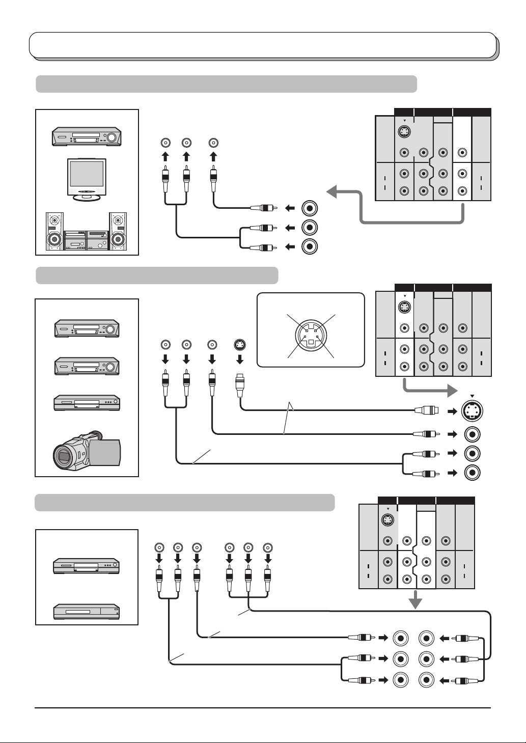
Audio / Video connections
How to connect the Monitor Output terminals to other Equipment
Example of output signal source
VCR
MONITOR
Amplifier to speaker system
AUDIOINVIDEO
IN
LR
MONITOR
OUT
MONITOR OUTAV1 IN AV2 IN
COMPONENT
S-VIDEO
VIDEO VIDEO
L/MONO
AUDIO
R
P
PR/CR
Y
B/CB
AUDIO
L
R
How to connect the AV1 Input terminals
Example of input signal source
VCR
AUDIO
OUT
VIDEO
OUT
LR
S-VIDEO VCR
DVD PLAYER
CAMCORDER
To receive monaural output, connect to AUDIO L/MONO terminal.
How to connect the DVD Input terminals
AUDIO
Example of input signal source
DVD PLAYER
Digital TV-SET-TOP-BOX
(DTV-STB)
OUT
VIDEO
OUT
LR
S-VIDEO 4 pin terminal
S-VIDEO
P
Chrominance in
OUT
Chrominance earth
Connect the S-VIDEO
or VIDEO terminal.
Y, PB, PR,
OUT
COMPONENT VIDEO OUT
R
Y
P
B
Luminance in
Luminance earth
MONITOR OUTAV1 IN AV2 IN
COMPONENT
S-VIDEO
COMPONENT
Y
P
B/CB
PR/C
R
P
PR/CR
Y
B/CB
MONO
MONITOR OUTAV1 IN AV2 IN
AUDIO
VIDEO VIDEO
L/MONO
AUDIO
R
S-VIDEO
VIDEO VIDEO
L/MONO
AUDIO
R
L
AUDIO
R
AV1 IN
L
R
Connect the VIDEO or COMPONENT
VIDEO terminal.
To receive monaural output, connect to
AUDIO L/MONO terminal.
Note:
Component input terminals are used for 525i/p or 625i/p signal.
8
MONO
AV2 IN
Y
B/CB
P
PR/C
R
 Loading...