

A
A
TX-22LX2
LH35 Chassis
ORDER NO. PCZ0408011C2
Wide LCD TV
Power Source
C 220-240V, 50/60Hz
Power Consumption
verage use: 90W
Standby condition: 1.3W
LCD
Wide XGA (1,280 × 720 pixels)
16 : 9 aspect ratio LCD panel
Screen Size
487.7mm(W) × 274.3mm(H)
Sound
Speaker
12cm × 4cm, 2pcs, 16W
Audio Output
6W (3W + 3W), 10% THD
Headphones
M3 (3.5 mm) Jack x 1
Receiving Systems/ Band name
PAL I
UHF E21 - 68.
PAL 525/60
Playback of NTSC tape from some PAL Video recorders
(VCR).
M.NTSC
Playback from M.NTSC Video recorders (VCR).
NTSC (AV input only)
Playback from NTSC Video recorders (VCR).
Aerial-Rear
UHF
Operating Conditions
Temperature: 5°C-35°C
Humidity: 5%-90% RH (non-condensing)
Connection Terminals
AV1 (Scart connecter)
21 Pin terminal (Audio/Video in, Audio/Video out, RGB in,
Q-Link)
AV2 (Scart connecter)
21 Pin terminal (Audio/Video in, Audio/Video out, S-Video
in, Q-Link)
AV3
VIDEO
RCA PIN Type × 1
S-VIDEO
Mini DIN 4-pin
AUDIO L-R
RCA PIN Type × 2
Dimensions (W x H x D)
Including TV Stand
592mm × 503.1mm × 260mm
TV Set Only
592mm × 420mm × 99mm
Weight
10kg Net
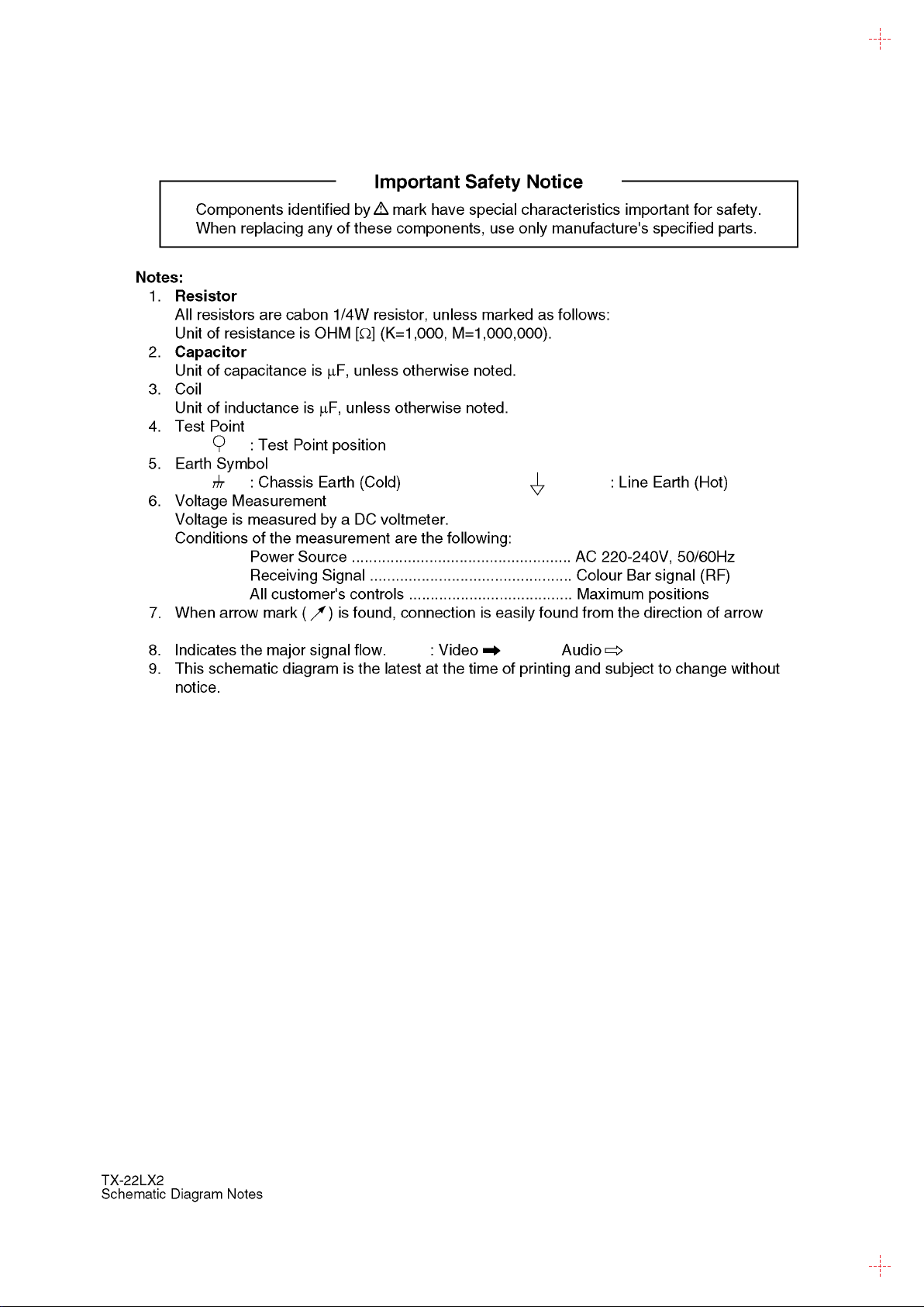
Note:
Design and Specifications are subject to change without notice.
Weight and Dimensions shown are approximate.
© 2004 Matsushita Electric Industrial Co., Ltd. All
rights reserved. Unauthorized copying and
distribution is a violation of law.
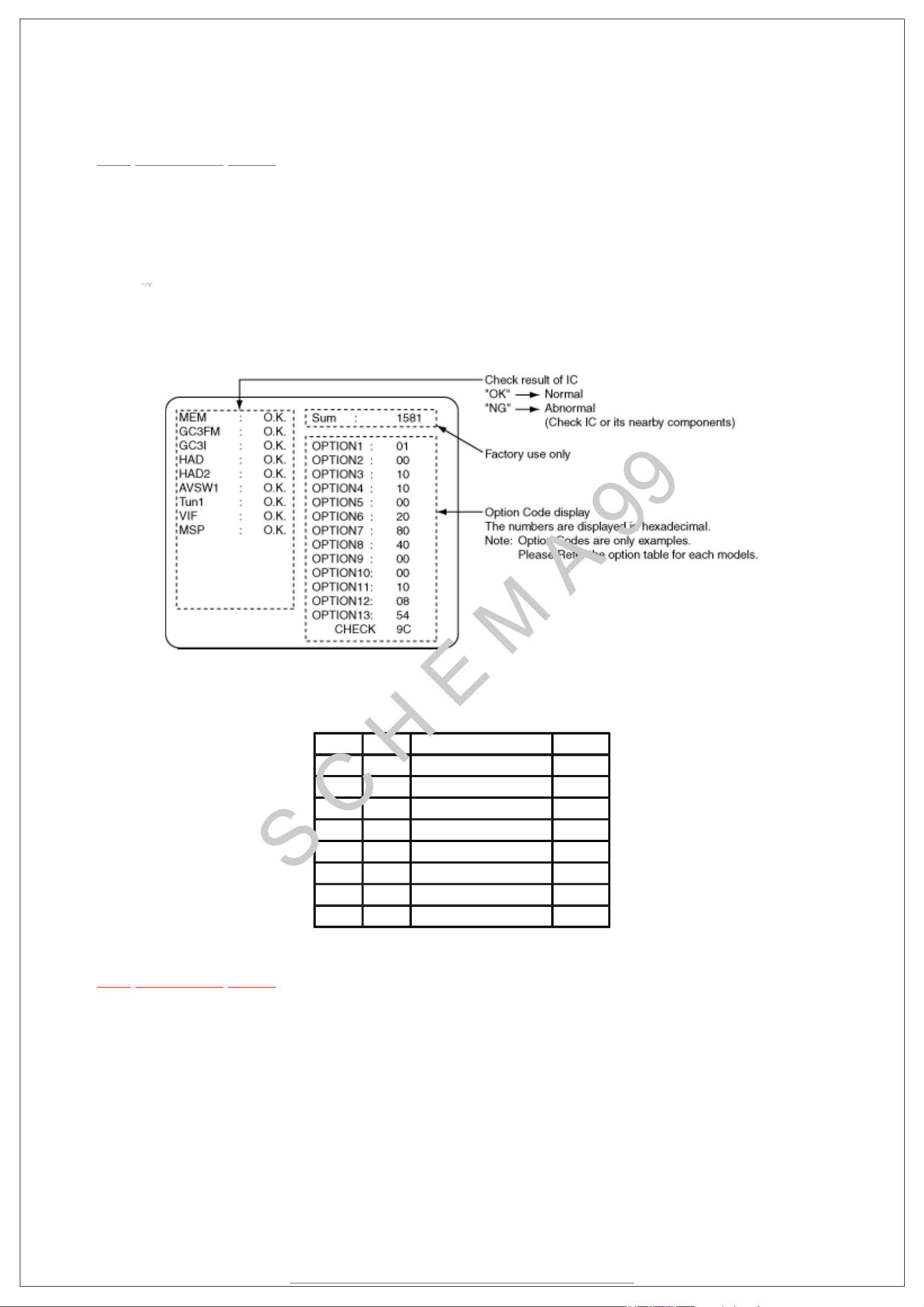
4 Self Check
TOP PREVIOUS NEXT
1.Self-Check is used to automatically check the bus lines and hexadecimal code of the TV set.
2.To get into the Self -Check mode press the Down (
) button on the customer controls at the front of the set, at the same time pressing the Recall
button on theremote control, and the screen will show :
3.Turn off the TV to reset JPEG Viewer circuit after SELF-CHECK.
If the CCU ports have been checked and found to be incorrect or not located then “--” will appear in
place of “O.K.”.
Display Ref .No. Description P.C.B.
MEM IC1107 EEPROM DG-Board
GC3FM IC4017 Global Core MAIN DG-Board
GC3I IC4003 Global Core DG-Board
HAD IC4001 SCART RGB A/D Converter DG-Board
HAD2 IC4002
AVSW1 IC3001 AV Selector A-Board
Tun1 TU101 Tuner B-Board
MSP IC2501 Stereo Decoder A-Board
OSD RGB A/D Converter DG-Board
TOP PREVIOUS NEXT
http://servis-manual.com/
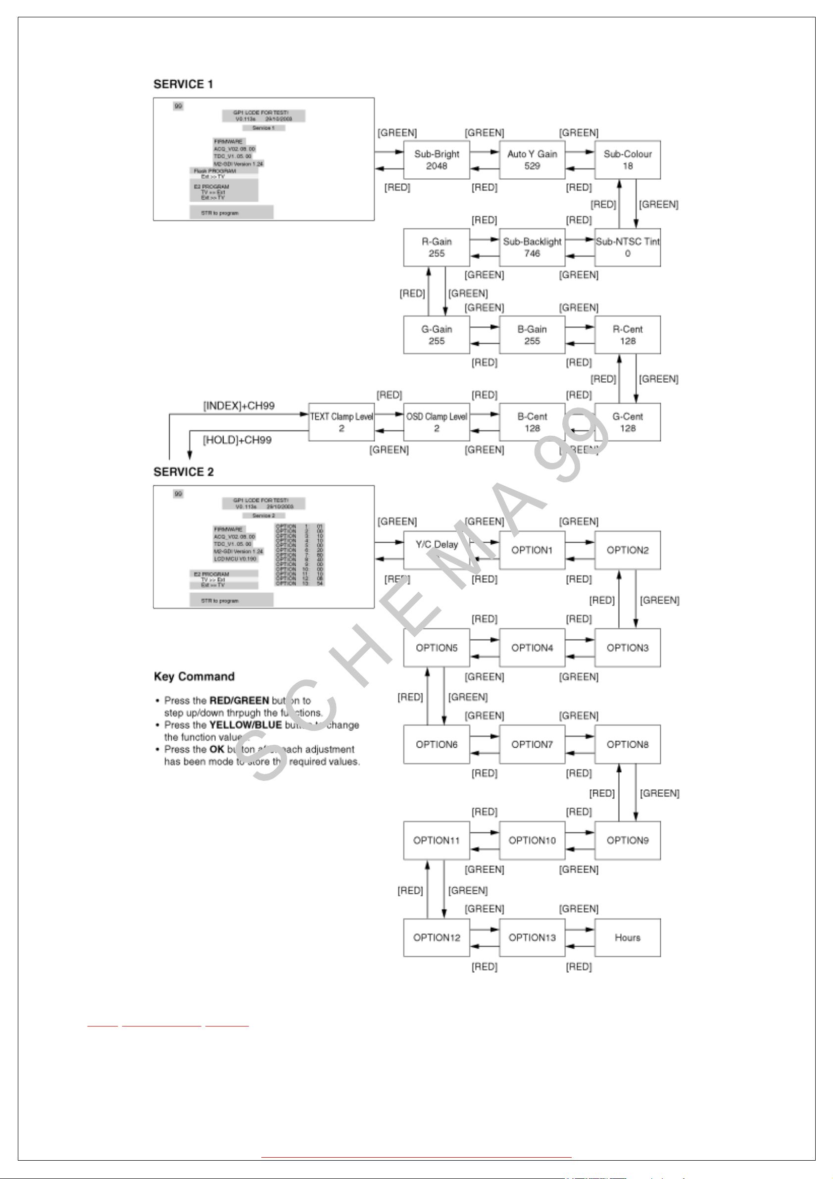
8.1 How to enter SERVICE 1
TOP PREVIOUS NEXT
1.In main menu, move to choose sound menu, set BASS to MAXIMUM, and set TREBLE to
MINIMUM.
2.Simultaneously press INDEX button on remote control and DOWN button [
] on the TV set.
TOP PREVIOUS NEXT
http://servis-manual.com/
8.2 How to enter SERVICE 2
TOP PREVIOUS NEXT
1.Select the TEXT Clamp Level (service 1).
2.Set the channel to CH99.
3.Press HOLD button on remote control.
Note:
To exit to Service mode, press N or Power button on remote control.
http://servis-manual.com/
TOP PREVIOUS NEXT
http://servis-manual.com/
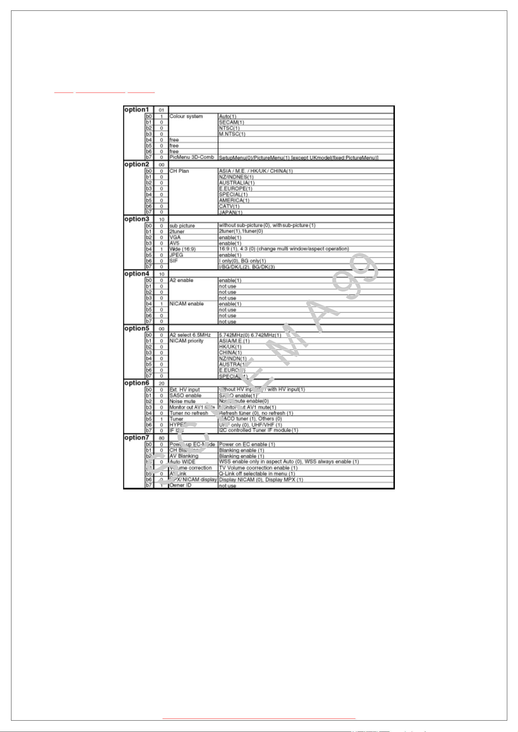
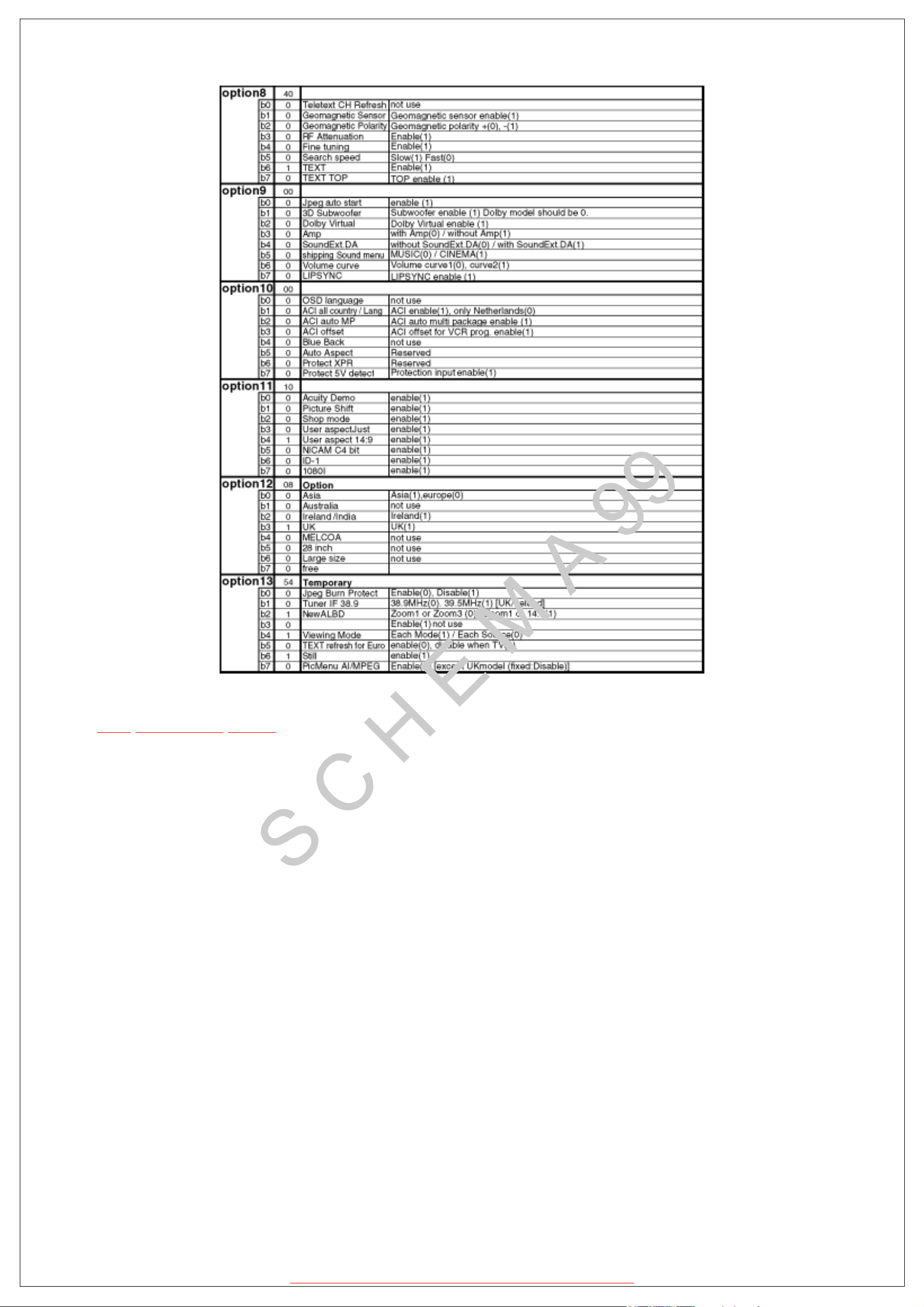
8.3 Option Description
TOP PREVIOUS NEXT
http://servis-manual.com/
TOP PREVIOUS NEXT
http://servis-manual.com/
9.1.1 RF video
TOP PREVIOUS NEXT
Instrument Name Connect to Remarks
Remote controller
Internal signal (studio color bar)
RF input
1.Receive full color bar by RF signal input.
(Aspect mode : wide, Viewing mode: standard, LCD AI: OFF)
2.Go to "Auto Y Gain" under Service 1 and make automatic adjustment of video signal level by
the blue key.
¡
When Service 1 appears, presetting takes place automatically as shown below.
¡
Sharpness: 0
¡ AI: OFF
¡
3D-Comb filter: On
3.Press STR key to write the value of adjustment results to EEPROM.
4.Check that the automatic adjustment of video signal level has completed normally.
¡ When the adjustment is completed normally, the "Auto Y Gain" color turns black.
Note:
In the adjustment mode, the M2 MCU changes automatically to the mode shown in the left.
TOP PREVIOUS NEXT
http://servis-manual.com/
9.2 WB Adjustment
TOP PREVIOUS NEXT
Instrument Name Connect to Remarks
1. Remote controller
2. LCD WB meter (Minolta CS-1000 equivalent)
3. Communication jig
4. Computer for external control
l
Basically perform checking using the production software and make automatic adjustment
Correlation can be also taken by CA-110 or equivalent
using external computer.
l
Let the panel stand for more than 3 hours at more than 20°C.
l
Basically perform assemble to completion in the ambient environment of room temperature
more than 20°C.
l
The aging time is more than 20 min at above room temperature.
1.Enter into WB adjustment in the plant adjustment mode and measure the WHITE brightness
data to check that it is higher than 400 cd /m2
(When it is below 400 cd /m2, make re-measurement in 30 minutes after cold-on.)
2.For the Excel calculation sheet, use "LX1 series, calculation software".
3.Using the jig, measure the brightness and chromaticity coordinates of single colors, white, red,
green and blue, at the maximum brightness (using basic data) and calculate the gamma data
corrected at the maximum brightness using Excel calculationsheet on the external computer.
4.Write the values calculated in 3 above in the gamma data part in EEPROM.
EEPROM Adr :
0C58h - 0C5Bh, 0C5Ch - C5Fh ...R(color temperature Normal)
0C08h - 0C0Bh, 0C0Ch - 0C0Fh ...G(color temperature Normal)
0C30h - 0C33h, 0C34h - 0C37h ...B(color temperature Normal)
5.Reflect the data in 4 above and select gray and measure the brightness and chromaticity
coordinate at that time and calculate the gamma data (color temperature, normal) and cool and
warm color temperatures, corrected at half-tone, using theexternal computer.
6.Write the values calculated in 5 above in the gamma data part in EEPROM.
EEPROM Adr:
0C58h - 0C5Bh, 0C5Ch - 0C5Fh ...R(color temperature Normal)
0C08h - 0C0Bh, 0C0Ch - 0C0Fh ...G(color temperature Normal)
http://servis-manual.com/
0C30h - 0C33h, 0C34h - 0C37h ...B(color temperature Normal)
0C50h - 0C53h, 0C54h - 0C57h ...R(color temperature Warm)
0C00h - 0C03h, 0C04h - 0C07h ...G(color temperature Warm)
0C28h - 0C2Bh, 0C2Ch - 0C2Fh ...B(color temperature Warm)
0C60h - 0C63h, 0C64h - 0C67h ...R(color temperature Cool)
0C10h - 0C13h, 0C14h - 0C17h ...G(color temperature Cool)
0C38h - 0C3Bh, 0C3Ch - 0C3Fh ...B(color temperature Cool)
7.Reflect the data in 6 above and CHECK that the chromaticity coordinates at check and GRAY,
are within the values given below.
CHECK: x= 0.264 ± 0.005 y= 0.269 ± 0.005
GRAY: x= 0.268 ± 0.005 y= 0.267 ± 0.005
¡
When writing data into EEPROM, make this procedure after sending the WP (write
protect) cancellation command (70 88 00).
Also, WP (write protect) setting command is 70 88 FF.
8.EEPROM DATA saving place for WB (gamma data) backup
<Housing address> <Writing address>
0C18h - 0C1Bh → 0C08h - 0C0Bh
0C1Ch - 0C1Fh → 0C0Ch - 0C0Fh
0C40h - 0C43h → 0C30h - 0C33h
0C44h - 0C47h → 0C34h - 0C37h
0C68h - 0C6Bh → 0C58h - 0C5Bh
0C6Ch - 0C6Fh → 0C5Ch - 0C5Fh
Note:
After completion of adjustment, record the completion time if it took more than 35 minutes after
aging.
LCD panels that do not fit in to the above check specification shall be discussed separately.
TOP PREVIOUS NEXT
http://servis-manual.com/
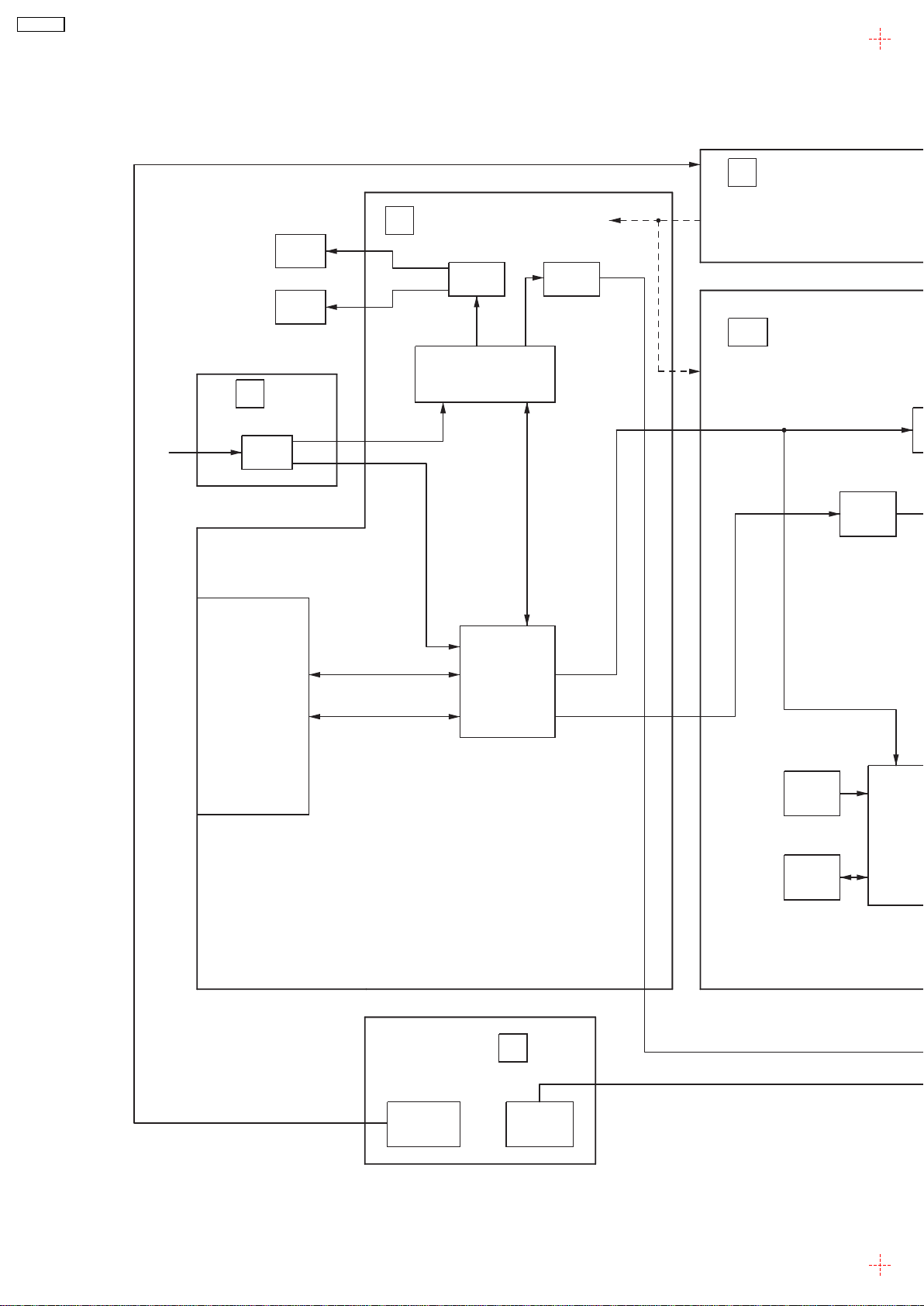
11 Block and Sche matic Diagrams
11.1. Schematic DiagramNotes
31
TX-22LX2
31
TX-22LX2
11.2. Main Block Diagram
B
SP
Left
SP
Right
P
UNIT
STB5V/REG5V
A
IC2100
Audio
Amp.
IC2200
HP
Amp.
INTERTER15V
UNREG32V
DG
Sound
processor
IC2501
PANEL VCC
STB5V,MAIN5V
STB3.3V,MAIN3.3V
MAIN1.8V,MAIN9V
IC4017
RF in
AV1
SCART
AV2
SCART
AV3/S
S-VIDEO
V
L,R
TU101
Tuner
L/R
V/R/G/B
TV_V
SIF
L/R
GC3FM
IC4002
RGB AD
AV
SW
V/Y
R/G/B
IC3001
IC1115
16M
FLASH
IC1104
IC1114
64M
SDRAM
TX-22LX2
Main Block Diagram
Main
Power SW
K
Key SW
32
 Loading...