

Panasonic TX-22LT2 User Manual
PICTURE
SOUND
SET UP
TV/AV
F.P. INDEX HOLD
TV/TEXT
DIRECT
TV REC
1
2 3
4
5 6
TX-22LT2
ASPECT
7
8 9
VCR
C
0
Operating Instructions
22˝ Diagonal LCD TV
TX-22LT2Model No.
X
T
Please read these instruction before operating your set and retain them for future reference.
2
T
L
2
2
-
TQBC 0356

Dear Panasonic Customer
Welcome to the Panasonic family of customers. We hope that you will have many
years of enjoyment from your new 22
″
Diagonal LCD TV.
To obtain maximum benefit from your set, please read these Instructions before
making any adjustments, and retain them for future reference.
Retain your purchase receipt also, and note down the model number and serial
number of your set in the space provided on the rear cover of these instructions.
Table of Contents
Warnings and Precautions...............................3
Before Operating This Set................................4
Supplied Accessories............................................. 4
Fitting remote control batteries .............................. 4
Receiver Location .................................................. 5
Optional External Equipment ................................. 5
For optimum quality picture ................................... 5
How to use the LCD stand..................................... 5
Quick start Guide ..............................................6
1. Choose Your Connection Type .......................... 6
2. Connecting the AC Adaptor ............................... 9
3. Switch TV ON .................................................... 9
4. Auto set up......................................................... 9
5. TV to VCR download ....................................... 10
6. Owner ID.......................................................... 11
7. The two basic functions ................................... 11
Basic controls ................................................. 12
Side panel controls and Remote control.............. 12
Using the On Screen Displays .......................15
Picture menu ................................................... 16
Sound menu .................................................... 18
Setup menu .....................................................20
Tuning menu-overview ................................... 21
Programme edit ................................................... 22
Auto setup............................................................ 24
Manual tuning ...................................................... 25
Shipping condition .............................................. 26
Owner ID.............................................................. 27
Aspect Controls .............................................. 28
Q-Link............................................................... 30
Tuning your VCR and satellite reciver ..........31
Advanced Remote Control Operation...........32
VCR / DVD Operation.......................................... 32
TELE TEXT.......................................................... 33
Connections .................................................... 36
How to connect the input terminals...................... 36
How to connect the AUDIO OUT terminals.......... 37
Connecting Headphones / Earphones................. 37
Troubleshooting.............................................. 38
Maintenance .................................................... 38
Specifications.................................................. 39
2
Warnings and Precautions
• This TV set is designed to operate on DC 15V.
•
To prevent damage which might result in electric shock
or fire, do not expose this TV set to rain or excessive
moisture. This TV must not be exposed to dripping or
splashing water and objects filled with liquid, such as
vases, must not be placed on top of or above the TV.
• WARNING : HIGH VOLTAGE!!!
Do not remove the rear cover as live parts are
accessible when it is removed. There are no user
serviceable parts inside.
• TV Games / Home Computers
Extended use of TV games or home computers with any
television set can cause a permanent ‘shadow’ on the
screen. This type of irreversible LCD panel damage, can
be limited by observing the following points:
• Reduce the brightness and contrast levels to a
minimum viewing level.
• Do not allow a still picture to be displayed for an
extended period, as this can cause a
permanent after-image to remain on the LCD
TV screen.
• Examples of still
games, computer images, teletext and images
displayed in 4:3 mode.
• This type of LCD panel damage, is not an
operating defect, and as such is not covered by
the Panasonic warranty.
pictures include logos, video
•The On/Off switch on this model does not fully
disconnect the TV from the mains supply. Remove the
mains plug from the wall socket when the TV set is not
used for a prolonged period of time.
Note:
• If the set is not switched off when the TV station
stops transmitting, it will automatically go to stand-by
mode after 30 minutes. This function will not operate
when the TV is in AV mode.
• Cabinet and LCD panel care
Remove the mains plug from the wall socket. The
cabinet and LCD panel can be cleaned with a soft
cloth moistened with mild detergent and water. Do not
use solutions containing benzol or petroleum.
•
When ambient temperature is cool, the picture may take a
short time to reach normal brightness, but this is not a
malfunction. (After brief moment, the picture will have normal
brightness.)
•
Adequate ventilation is essential to prevent failure of
electrical components, we recommend that a gap of at least
10cm is left all around this television receiver even when it is
placed inside a cabinet or between shelves.
• Avoid exposing the TV set to direct sunlight and other
sources of heat.
FOR YOUR SAFETY PLEASE READ THE FOLLOWING TEXT CAREFULLY
This appliance is supplied with a fitted three pin mains plug for your safety and convenience. A 5 amp fuse is
fitted in this plug. If the fuse is replaced then the replacement fuse must be 5 amp rated and should be approved
by ASTA or BSI to BS1362.
Check for the ASTA mark or the BSI mark on the body of the fuse.
If the fitted plug has a removable fuse cover you must ensure that it is refitted when the fuse is replaced. If you
lose the fuse cover the plug must not be used until a replacement cover is obtained. Replacement fuse covers
can be purchased through your local Panasonic dealer.
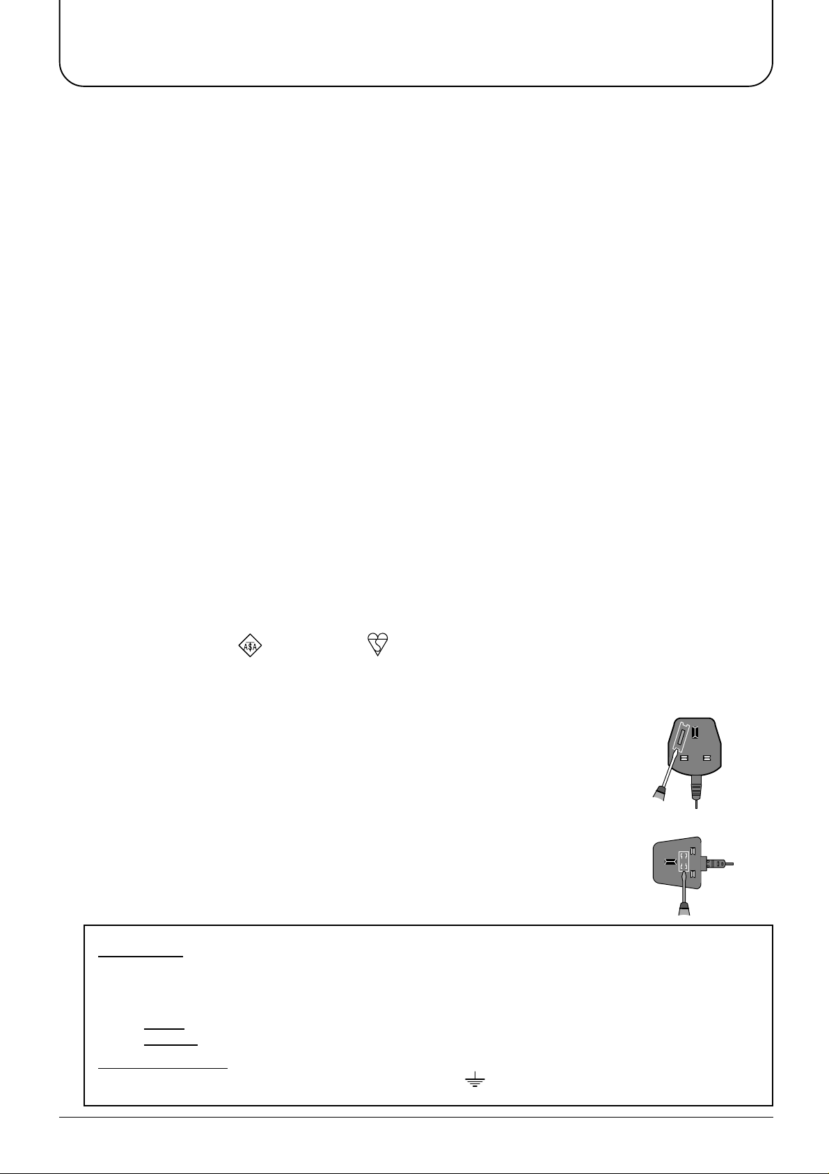
If the fitted moulded plug is replaced, the fuse should be taken out and the cut-off
plug disposed of safely. There is danger of severe electrical shock if the cut off
plug is inserted into any 13 amp socket.
If a new plug is to be fitted please observe the wiring code as shown below.
If in any doubt please consult a qualified electrician.
How to replace the fuse (for plug type shown in example 1):
Lift out the removable fuse compartment with a screwdriver and replace the fuse, then
refit securely into the mains plug (see example 1).
How to replace the fuse (for plug type shown in example 2):
Lift open the fuse compartment, in the mains plug, with a screwdriver, and replace the
fuse, then press the fuse cover down securely (see example 2).
IMPORTANT: -
The wires in the mains lead of this appliance are coloured in accordance with the following code :-
BLUE : NEUTRAL BROWN : LIVE
Example 1
Example 2
As the colours of the wires in the mains lead of this appliance may not correspond to the markings
identifying the terminals in your plug, proceed as follows :-
1. The BLUE wire must be connected to the terminal marked ‘N’ or coloured black.
2. The BROWN wire must be connected to the terminal marked ‘L’ or coloured red.
IMPORTANT NOTE:
the three pin plug, marked with the letter ‘E’ or the earth symbol.
Under no circumstances should either of these wires be connected to the Earth terminal of
3
Before Operating This Set
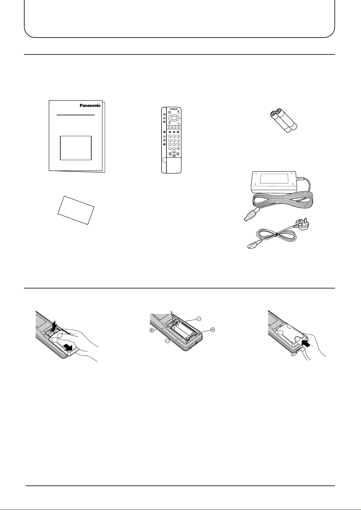
Supplied Accessories
Check the accessories before installations.
Operating Instruction book
•
(TQBC0356)
Warranty Card
•
Remote Control Transmitter
•
(EUR511252)
PICTURE
SOUND
SET UP
TV/AV
F.P. INDEX HOLD
TV/TEXT
DIRECT
TV REC
1
2 3
4
5 6
ASPECT
7
8 9
VCR
C
0
Batteries for the Remote Control
•
Transmitter
(2 × R6 (UM3) size)
AC Adaptor & Main Lead
•
AC Adaptor: (N0JZHK000004)
Main Lead: (K2CT3AA00001)
Fitting remote control batteries
1
Slide off the battery cover
• Make sure that the batteries are fitted the correct way round.
• Do not mix old batteries with new batteries. Remove old, exhausted batteries immediately.
• Do not mix different battery types, i.e. Alkaline and Manganese or use rechargeable (Ni - Cad) batteries.
23
Two “R6 (UM3)” size
Insert batteries - note
correct polarity (+ and -)
Replace the cover
4
Before Operating This Set
Receiver Location
Locate for comfortable viewing. Avoid placing where sunlight or other bright light (including reflections) will fall on
the screen.
Use of some types of fluorescent lighting can reduce remote control transmitter range.
Adequate ventilation is essential to prevent internal component failure. Keep away from areas of excessive heat
or moisture.
To insure optimum picture do not position magnetic equipment (motors, fans, other speakers, etc.) nearby.
Optional External Equipment
The Video/Audio connection between components can be made with shielded video and audio cables. For best
performance, we recommend 75 ohm coaxial aerial cable is used. Cables are available from your dealer or
electronic supply store.
Before you purchase any cables, be sure you know what type of output and input connectors your various
components require. Also determine the length of cable you’ll need.
For optimum quality picture
When the LCD is exposed to light from outdoors or lighting fixtures, high-contrast pictures may not be displayed
clearly. Turn off florescent lamps near the LCD and place in a location not exposed to outdoor light.
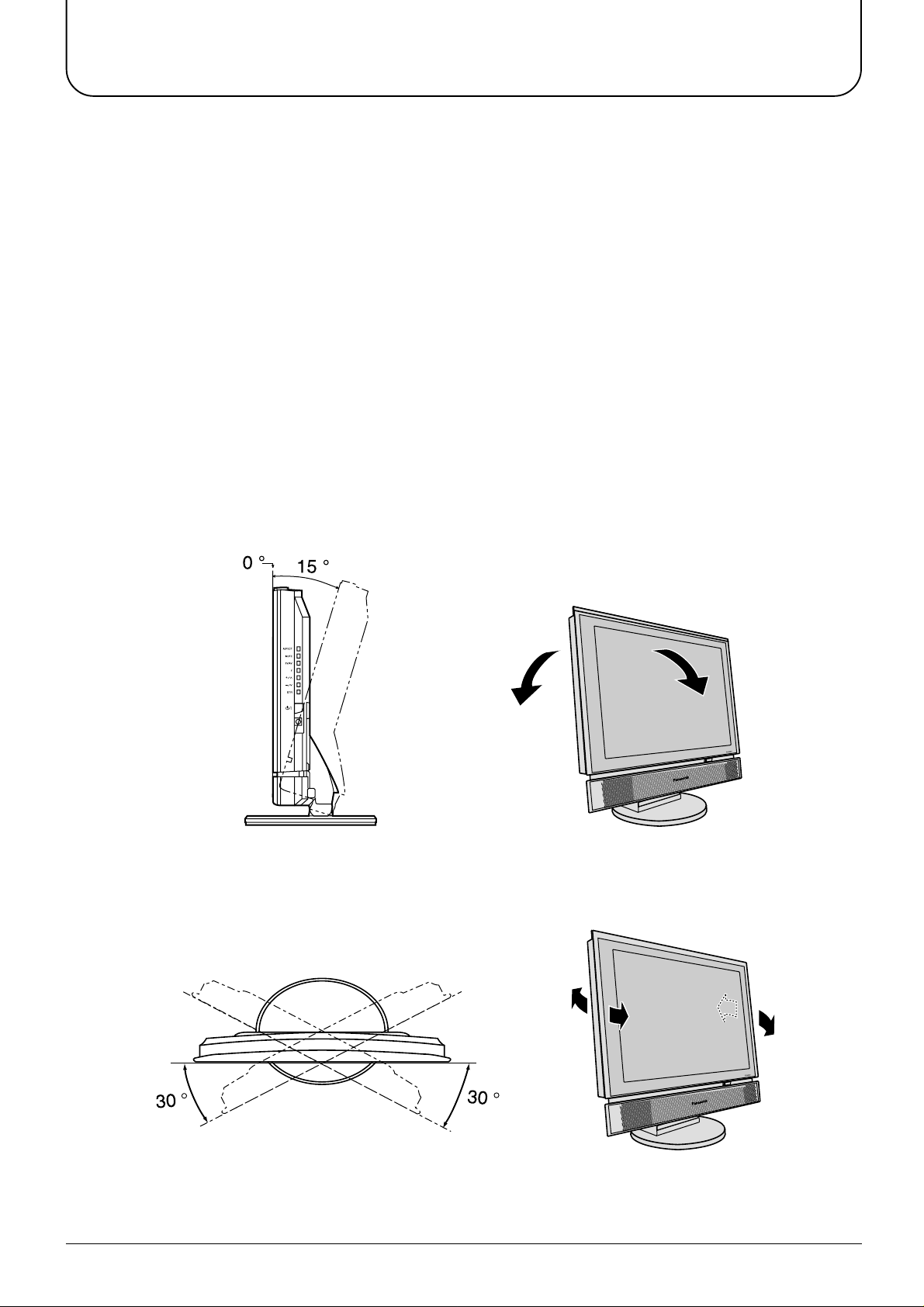
How to use the LCD stand
Adjust the stand to your desired angle. The stand angle can be adjusted between 0 ° to 15 ° back, 30 ° left and
30 ° right.
5
Quick start Guide
1. Choose Your Connection Type
Connection and setting up options
• If connecting the TV using an RF cable only, see below.
• If connecting the TV using Scart and RF cables, see page 7.
• If connecting the TV to a Q-Link (or Q-Link compatible) VCR, see page 7.
• If connecting the TV to a Q-Link (or Q-Link compatible) VCR and a satellite receiver, see page 8.
What is Q-Link?
Q-Link allows direct communication between the TV and a Q-Link (or Q-Link compatible) VCR, this will enable
features such as downloading of tuning information from the TV to the VCR.
When using a “NEXTVIEWLINK” VCR the main features possible are the following:
• Preset Download Downloading of tuning information from the TV to the VCR.
• Direct TV Record
When using a “Q-Link” VCR the main features possible are the following:
• Preset Download Downloading of tuning information from the TV to the VCR.
• Direct TV Record For immediate recording of the current program (What You See Is What You
• TV/VCR Auto Power On When the VCR plays a tape the TV will automatically switch On (From Stand-
• VCR Auto Power Stand-by When the TV is switched into Stand-by, the VCR will also switch into Stand-by .
• VCR Image view On If the TV is in Stand-by mode and the VCR sends a menu to be displayed on
For immediate recording of the current program (What You See Is What You Record).
Record).
by) and select the AV2 input.
the TV screen (e.g. Main menu), the TV will automatically switch On and the
menu will be displayed.
This TV will also communicate with other VCRs that bear the following logos:
• “DATA LOGIC” (a trademark of Metz Corporation).
• “Easy Link” (a trademark of Philips Corporation).
• “Megalogic” (a trademark of Grundig Corporation).
• “SMARTLINK” (a trademark of Sony Corporation).
These VCRs may support some or all of the above funcitons. Refer to the VCR operating instruction book.
Further information on Q-Link can be found on page 30.
In order for Q-Link to function correctly, the Scart cables must be connected in a certain way, dependent on
whether the TV is being connected to a VCR or to a VCR and Satellite Receiver.
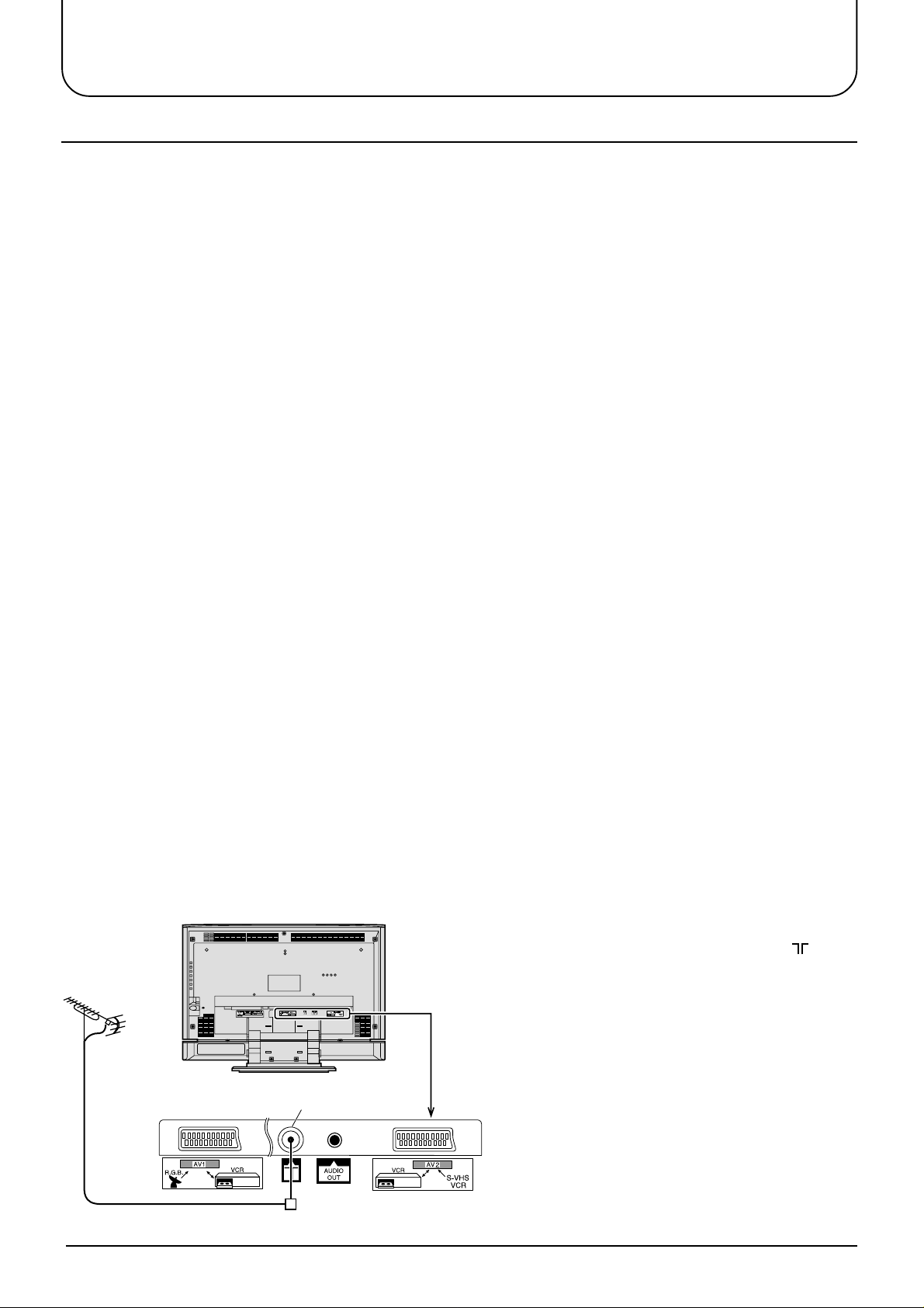
1. Connecting the TV directly to an aerial only
RF connection
LCD TV
Aerial
(Not Supplied)
Connect the Aerial lead into the TV Aerial socket ( ).
6
Aerial Input socket
Aerial Lead
Quick start Guide
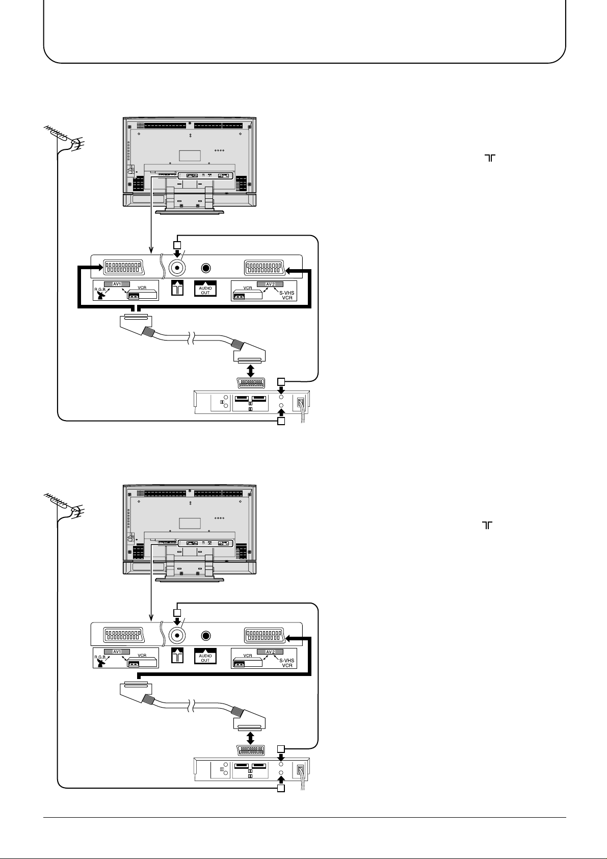
2. Connection of TV and VCR using Scart and RF cables
RF connection
Connect the AERIAL to the Aerial in socket of the
VCR and an RF cable from the VCR Aerial Out
socket to the TV Aerial socket ( ).
Scart Connections
The VCR can also be connected to the TV using
a Scart cable if you are using a Scart equipped
VCR.
• Use the TV’s AV1 Scart socket for a VCR.
• Use the TV’s AV2S Scart socket for an S-Video
VCR.
Aerial
(Not Supplied)
AV1,AV2
Scart sockets
LCD TV
Aerial Input socket
Notes:
• Additional equipment and cables are not
supplied.
• Further details of audio / video connections can
be found on pages 36 and 37.
Aerial Lead
Scart socket
VCR
AV1
Aerial
Input
socket
Aerial
Output
socket
3. Q-Link connection of TV and VCR using Scart and RF cables
RF connection
Connect the AERIAL to the Aerial in socket of the
LCD TV
Aerial
(Not Supplied)
Aerial Input socket
VCR and on RF cable from the VCR Aerial Out
socket to the TV Aerial socket ( ).
Scart connection
The VCR must be connected to the AV2 Scart
socket of this TV using a ‘fully wired’ Scart cable.
Note:
If using a “Q-Link” VCR then the AV1 Scart of the
VCR must be connected to the AV2 socket of the
TV. If your VCR is not a “Q-Link” VCR, please
consult your VCR operating instruction book.
AV2
Scart socket
Aerial Lead
Scart socket
VCR
AV1
Aerial
Input
socket
Aerial
Output
socket
Notes:
• Additional equipment and cables are not
supplied.
• Further details of audio/ video connections can
be found on page 36 and 37.
• Further information for VCR and Satellite
Receiver installation with this TV can be found
on page 31.
7
Quick start Guide
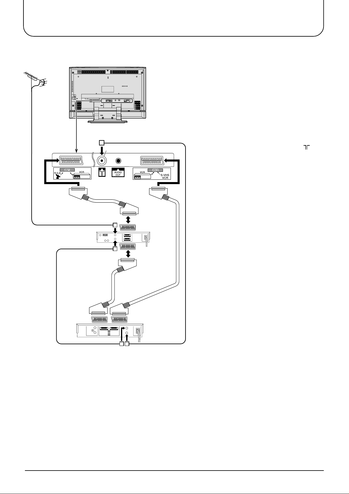
4. Q-Link connection of TV, VCR and Satellite using Scart and RF cables
For Q-Link to function correctly the TV, VCR
and Satellite Receiver must be connected as
shown in the diagram below.
RF connections
• Connect an RF cable to the Aerial In socket
of the Satellite Receiver.
• Connect an RF cable from the RF Out
socket of the Satellite Receiver to the RF In
socket of the VCR.
• Connect an RF cable from the RF Out socket
to the VCR of the TV Aerial In socket ( ).
Scart connections
‘Fully wired’ Scart Cables should be used for
all of the Scart connections.
• The AV2 Scart of the VCR must be
connected to the VCR socket of the Satellite
Receiver.
• The TV Scart socket of the Satellite
Receiver must be connected to the AV1
Scart socket of the TV.
Note:
If using a “Q-Link” VCR then the AV1 Scart
of the VCR must be connected to the AV2
socket of the TV. If your VCR is not a “Q-
Link” VCR, please consult your VCR
operating instruction book.
Aerial
(Not Supplied)
AV1
Scart socket
Aerial Input socket
Aerial Input
socket
Aerial
Output
socket
AV2
Scart socket
TV
Scart
socket
VCR
Scart
socket
LCD TV
Satellite
Receiver
8
AV2
Scart
socket
Aerial
Input
socket
AV1
Scart
socket
Aerial
Output
socket
VCR
Notes:
• Additional equipment and cables are not
supplied.
• Further details of audio/ video connections
can be found on pages 36 and 37.
• Further information for VCR and Satellite
Receiver installation with this TV can be
found on page 31.
Quick start Guide
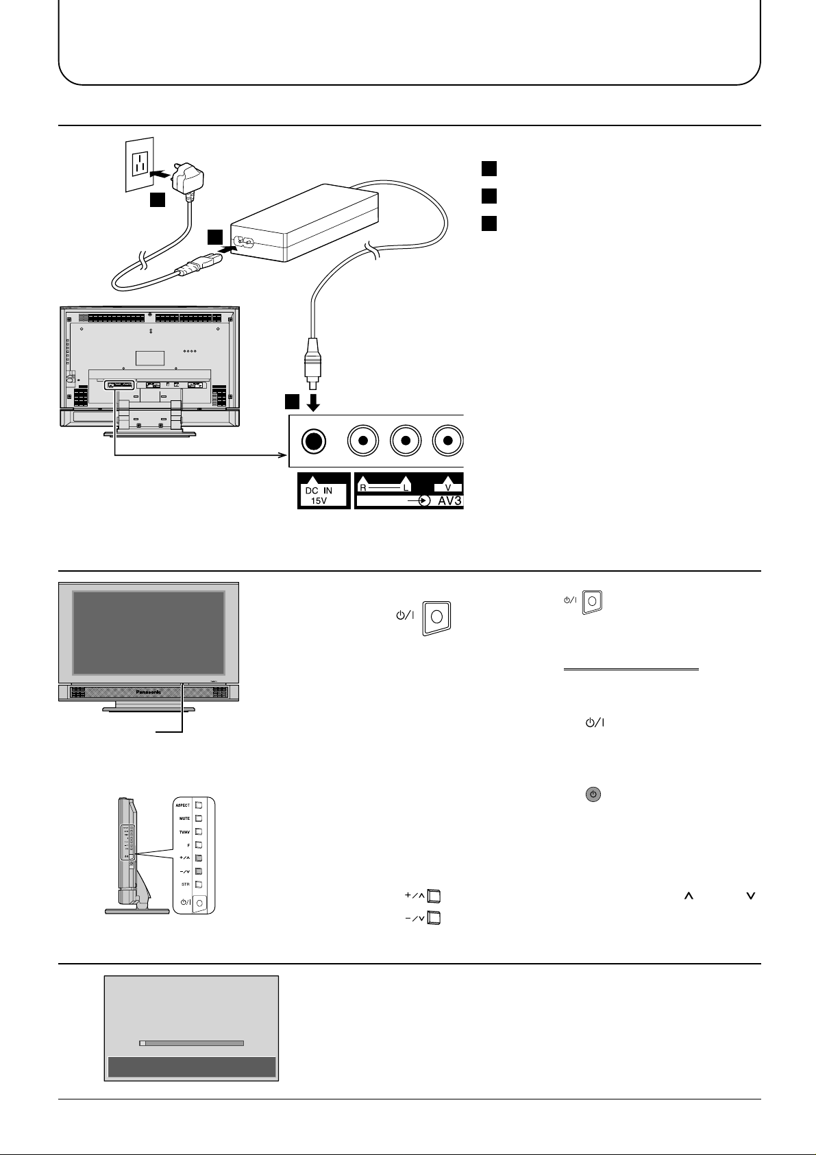
2. Connecting the AC Adaptor
3
First, ensure that the VCR is in Stand-by mode.
1
Connect the mains lead to the AC Adaptor.
2
Connect the AC Adaptor DC plug to the DC IN socket.
1
3. Switch TV ON
3 Plug into household mains socket.
• Be sure to use the power cord and AC
adaptor included in the accessories.
• Do not use the AC adaptor for other than
the specified equipment.
• Unplug the AC adaptor if it is not used for
long time.
• Do not place any objects on the AC adaptor.
• Do not use the AC adaptor outdoors.
• Do not attempt to repair the AC adaptor if it
2
is broken or malfunctioning. Refer the
servicing to the service representative.
• Do not try to open the AC adaptor.
• Do not use water or wet cloth for cleaning
the AC adaptor.
Press the switch on the LCD TV to
Power-Indicator
The RED LED when lit indicates that not
only the TV set is in stand-by mode but
also the external AC adaptor is still on.
4. Auto set up
AUTO SETUP IN PROGRESS
SEARCHING:PLEASE WAIT
turn the set on.
IMPORTANT NOTES
There are two ways to switch the TV set to
stand-by mode.
(A) Press the switch on the LCD TV
and check RED LED is lit.
OR
(B) Press the Stand-by button on the
remote control.
The TV set cannot be switched on by the remote
controller if it was switched to stand-by using
method (A) or vice versa if method (B) was used.
When programme number up ( )/down ( )
buttons on the side panel of the main part
are pressed in stand-by mode, TV turns on.
Programmes will appear immediately if your dealer has
programmed the TV for you.
21 68
SETUP : Return to tuning menu
TV/AV : To exit
If the TV has not been programmed for you then Auto setup
will begin, your stations will be located, sorted into order and
stored ready for use.
9
Quick start Guide
5. TV to VCR download
If a Q-Link, NEXTVIEWLINK or compatible VCR has been connected to the
AV2 socket before starting Step 1, programme information will be downloaded
TV −> VCR DOWNLOAD IN PROGRESS
PLEASE WAIT
Programme : 63
Remote control unavailable
Notes:
If the VCR has not accepted download data from the TV, you may need to select the Download option from the
VCR’s menu system.
Refer to the VCR operating instruction book.
If Q-Link is not operating correctly, check the following:
• The Scart cable is connected to the TV’s AV2 Scart socket.
• The Scart cable is connected to the VCR’s compatible (Q-Link, NEXTVIEWLINK or similar technology) Scart
socket.
• The Scart cable is a “fully wired” type.
to the VCR.
Downloaded tuning data will match the television’s.
Not all VCRs support this download of programme information, some may
require to be started manually. Refer to the VCR operating instruction book.
If a VCR other than those described above has been connected, then there will
be no download operation.
For further information on Q-Link and connecting equipment, see pages 13, 30 and 36.
• The sorted programme order depends upon the TV signal, the broadcasting system, and reception conditions.
If the order is not to your preference it can be rearranged. Refer to the Programme edit menu - see page 22 for
details.
• If you have an analogue satellite receiver, select ‘SKY ONE’ or ‘SKY NEWS’ on the receiver before starting
Auto Setup.
After Auto Setup is complete, the satellite position will be shown as ‘SAT’ in the channel listing to denote
programmes from the satellite receiver.
• If you have a digital satellite receiver, you can start Auto setup with the receiver set to any channel. You will
then have to manually name the ‘SAT’ position after Auto setup is complete. Refer to the Programme edit menu
- see page 23 for details.
Prog. Position All channels No CH5
1 BBC1 BBC1 BBC1 BBC1 BBC1 BBC1 BBC1
2 BBC2 BBC2 BBC2 BBC2 BBC2 BBC2 BBC2
3 ITV ITV ITV ITV ITV ITV ITV
4 CH4 CH4 CH4 S4C CH4 CH5 SAT
5 S4C S4C SAT SAT CH5 SAT
6 CH5 SAT
7SAT
Note:
The next available channel will appear, if no other stations are available then the Programme position will
remain unused.
°
°°°°°°
No CH5 / S4C
No CH4 / CH5 No S4C
°°
SAT
No CH4 / S4C
No CH4 / S4C / CH5
°
°°
10
Quick start Guide
REC VCR
DVD
PROGRAMME
N
STR
F.P. INDEX HOLD
PICTURE
SOUND
SET UP
TV/TEXT
ASPECT
TV/AV
1
2 3
4
5 6
7
8 9
C
0
VCR
DIRECT
TV REC
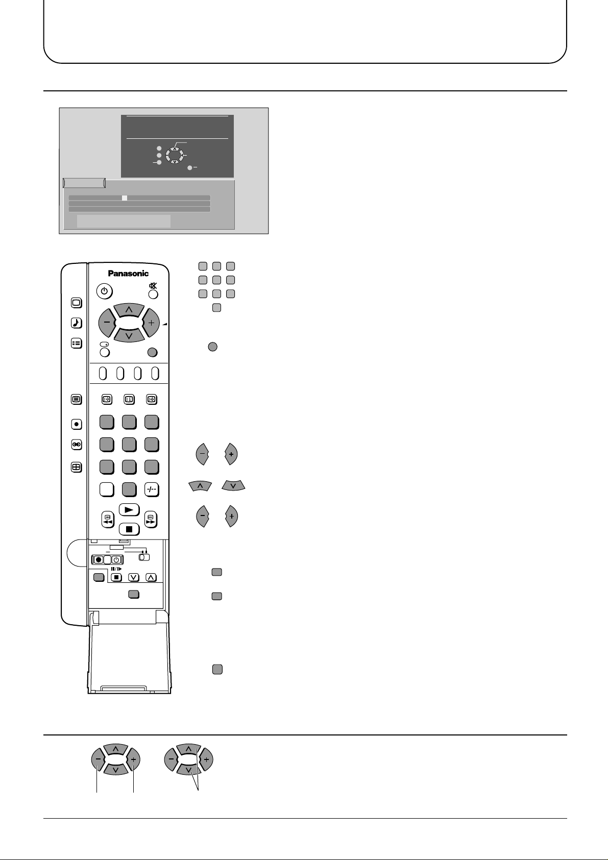
6. Owner ID
You now have the opportunity
to enter your details and
help the police crack crime
see instruction book
Return
Owner ID
PIN NUMBER :
HOUSE NO :
POST CODE :
ABCDEFGHIJKLMNOPQRST
UVWXYZ
∗∗∗∗
NAME :
∗∗∗∗∗∗∗∗∗∗∗∗∗∗
∗∗∗∗∗∗∗∗∗∗∗
∗∗∗∗∗∗∗∗∗∗∗
+− .
0123456789
Change
Character
Select
character
'STR' Button - Store Owner ID
TV/AV
Exit
1
4
7
23
56
89
0
TV/AV
As an added feature, this TV has the option of
entering a security code (Owner ID) and personal
details into its memory, so that in the unfortunate
event of theft it will help the police to trace the owner.
Enter required 4 digit Owner ID PIN NUMBER (using 0 to 9 on the
remote control)
Press the TV/AV button at any time to exit the Owner ID feature
without saving any information you may have entered.
Enter NAME, HOUSE NUMBER and POSTCODE
STR
STR
N
If a 4 digit PIN NUMBER was entered above, you will be taken
automatically to the NAME line.
If not, move to the NAME line.
Change character.
Select character position.
Repeat above until NAME, HOUSE NUMBER and POSTCODE are entered.
Press STR to store the details.
Press STR again, when you are asked “Are you sure?”
For further information on Owner ID, including how to view the
details you have stored, see page 27.
A space is provided on page 27 to write down your PIN NUMBER for future reference.
We recommend that as soon as you have stored Owner ID details (or have
exited the feature), the picture controls are reset to normal viewing levels. To
do this, press the “N” button, found under the remote control’s pull down flap.
7. The two basic functions.
Adjust Volume
Change
Programme
You are now ready to begin viewing programmes
The cursor controls provide the two basic functions:
11
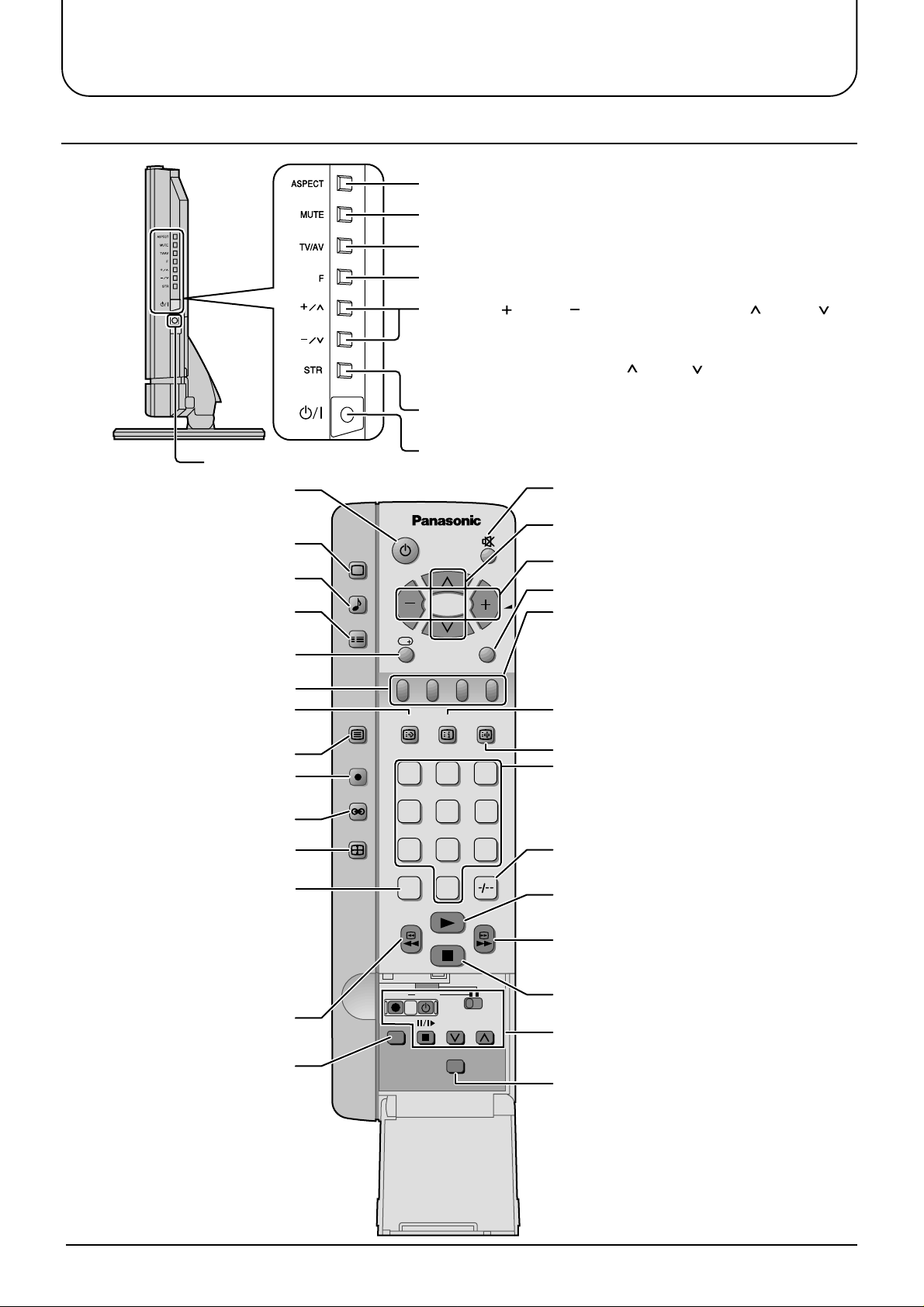
Basic controls
Side panel controls and Remote control
Aspect (see page 28, 29)
Sound mute (see page 13)
TV/AVmode Selection (see page 13)
Function button (see page 14)
Volume Up ( ), Down ( )/ Programme Number Up ( ), Down ( )
Volume adjustment which uses these buttons is performed
after pressing Function button. (see page 14)
When programme number up ( )/down ( ) buttons on the side
panel of the main part are pressed in stand-by mode, TV turns on.
Store (see page 14)
Headphone Jack (M3 jack)
TV ON / Stand-by (see page 9)
Picture menu (see page 16)
Sound menu (see page 18)
Set up menu (see page 20)
Recall(see page 14)
TELE TEXT (see page 33)
TEXT Favourite page selection
(see page 34)
TV/TEXT selection (see page 33)
Direct TV Record button
(see page 30)
Ambience (see page 19)
Aspect (see page 28, 29)
Direct channel access
During normal TV viewing or when
in the Tuning, programme edit or
Manual tuning menus, press and
then enter channel number using
the numeric buttons
VCR/DVD Rewind/Review
(see page 32)
Normalization
Resets all settings to their
default levels
PICTURE
SOUND
SET UP
TV/TEXT
DIRECT
TV REC
ASPECT
TV ON / Stand-by (see page 9)
TV/AV
F.P. INDEX HOLD
1
2 3
4
5 6
7
8 9
VCR
C
0
DVD
REC VCR
N
PROGRAMME
STR
Sound mute (see page 13)
Programme Number Up and Down
(see page 11)
Volume Up and Down (see page 11)
TV/AV mode selection (see page 13)
Coloured buttons used for
Aspect functions (see page 28)
Programme edit functions (see page 22)
Teletext functions (see page 33)
AV selection (see page 13)
TEXT Index (see page 34)
TEXT hold (see page 34)
Programme / Channel change buttons
(0-9) and Teletext page buttons
(see page 13, 33)
When in Stand-by mode, switche TV On.
Two Digit- programme Number
selection (see page 13)
VCR/DVD Play (see page 32)
VCR/DVD Fast Forward/cue
(see page 32)
VCR/DVD Stop (see page 32)
VCR/DVD Control (see page 32)
Store (see page 14)
12
 Loading...