

Panasonic TX-14GV2 User Manual
T X --- 1 4 G V 2
Colour TV---Video
Combination
(U.K. Standard)
R
Operating Instructions
TQB8E3833
WARNINGS AND PRECAUTIONS
D
D
This TV---Video is designed to operate on 220--240V, 50Hz
A.C.
D
To prevent damage which might result in electric shock or
fire, do not expose this TV ---Video to rain or excessive
moisture.This TV must not be exposed to dripping or
splashing water and objects filled with liquid, such as
vases, must not be placed on top of or above the TV.
D
WARNING : HIGH VOLTAGE !!!
Do not remove the rear cover as live parts are accessible
when it is removed. There are no user serviceable parts
inside.
D
Avoid exposing the TV---Video to direct sunlight and other
sources of heat.
D
The On/Off switch on this model does not fully disconnect
the TV---Video from the mains supply. Remove the mains
plug from the wall socket when the TV---Video is not used
for a prolonged period of time.
FOR YOUR SAFETY PLEASE READ THE FOLLOWING TEXT CAREFULLY
This appliance is supplied with a fitted three pin mains plug for your safety and convenience. A 5 amp fuse is fitted in this plug. If the
fuse is replaced then the replacement fuse must be 5 amp rated and should be approved by ASTA or BSI to BS1362.
CABINET AND PICTURE TUBE CARE
Remove the mains plug from the wall socket. The cabinet
and picture tube can be cleaned with a soft cloth moistened
with mild detergent and water. Do not use solutions
containing benzol or petroleum. TVs can produce static
electricity, care must be taken whenever touching the TV
screen.
D
Adequate ventilation is essential to prevent failure of
electrical components, we recommend that a gap of at least
5cm is left all around this television receiver even when it is
placed inside a cabinet or between shelves.
D
Playback and recording of S---VHS type tapes is not
possible on this unit.
D
To prevent fire,never placeany typeof candleor nakedflame
on top of, or near the TV set.
Check for the ASTA mark
If thefittedplug has aremovable fuse coveryoumust ensure thatitis refitted when thefuse is
replaced. If you lose the fuse cover the plug must not be used until a replacement cover is
obtained. Replacementfuse coverscan be purchased through yourlocal Panasonic dealer.
The plug fitted to this appliance incorporates a mains filter circuit. If this is removed or
replaced with a non--filtered plug this television will no longer meet the European
standards for Electromagnetic Compatibility (EMC). If thefitted plug is unsuitable for
the socket outlet in your home an appropriate adapter should be used.
Nonetheless,if thefitted plug is replaced, thefuse shouldbe taken out and thecut--off
plug disposed of safely. There is danger of severe electrical shock if the cutoff plug is
inserted into any 13 amp. socket.
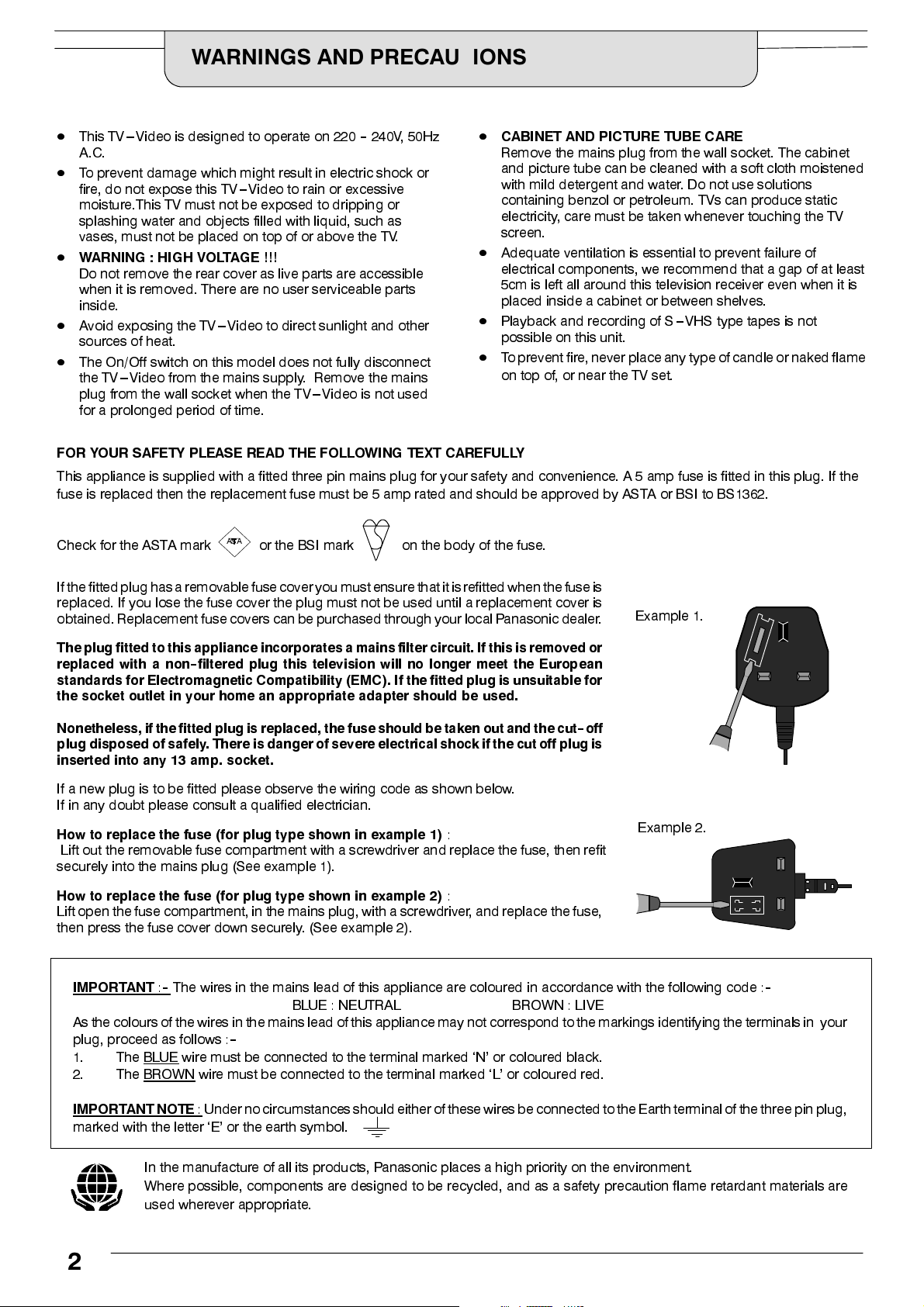
If a new plug is to be fitted please observe the wiring code as shown below.
If in any doubt please consult a qualified electrician.
How to replace the fuse (for plug type shown in example 1)
Lift out the removable fuse compartment with a screwdriver and replace the fuse, then refit
securely into the mains plug (See example 1).
How to replace the fuse (for plug type shown in example 2)
Lift open the fuse compartment,in the mains plug,with a screwdriver, and replace the fuse,
then press the fuse cover down securely. (See example 2).
IMPORTANT:--
As thecolours of the wiresin the mains lead ofthis appliancemay not correspond to the markings identifying the terminalsin your
plug, proceed as follows :
1. The BLUE
2. The BROWN
The wires in the mains lead of this appliance are coloured in accordance with the following code :
ASA
or the BSI mark on the body of the fuse.
:
:
BLUE : NEUTRAL BROWN : LIVE
--
wire must be connected to the terminal marked ‘N’ or coloured black.
wire must be connected to the terminal marked ‘L’ or coloured red.
Example 1.
Example 2.
--
IMPORTANT NOTE
marked with the letter ‘E’ or the earth symbol.
In the manufacture of all its products, Panasonic places a high priority on the environment.
Where possible, components are designed to be recycled, and as a safety precaution flame retardant materials are
used wherever appropriate.
: Under no circumstancesshould either ofthese wires beconnected to theEarth terminal ofthe three pin plug,
2
WELCOME
Dear Panasonic Customer,
Welcome to the Panasonic family of customers. We hope that you have many years of enjoyment from your
newcolourTV---Video combination. Thisis a veryadvanced unit;however,the Quick StartGuide will allowyou
to use the TV---Video as quicklyas possible.You can then readthe instructions completelyand retain themfor
future reference.
CONTENTS
Page Page
Accessories 4.....................................
Inserting the remote control batteries 4..............
Basic controls 5...................................
Quick start guide 6................................
On screen displays 10.............................
Main Menu
Picture adjustments 11............................
TV setup menu
Aspect 12.......................................
Off timer 13.....................................
On / Off timer 14.................................
Tuning menu --- overview 15.......................
Programme edit 16.........................
Delete a programme position 17..........
Swap two programme positions 17........
Name a programme position 18...........
Lock a programme channel 18............
Auto setup 19.............................
VCR setup menu
Auto repeat 24...................................
VCR Child lock 24................................
Record Speed 24................................
Clock --- date and time 25.........................
VCR operation --- basic controls 26..................
VCR indicators 27.................................
Recording
Manual recording 28..............................
One touch recording (OTR) 28.....................
Timer programme recording (manual entry) 29.......
VIDEO Plus+Rrecording 31.......................
Daily / weekly recordings 32.......................
Programme Delivery Control (PDC) 33...............
Index 34.......................................
Teletext operation 35...............................
Connections
Front AV inputs and headphone socket 37...........
Rear AV input (SCART socket) 37...................
Manual tuning 20..........................
Manual tuning (front panel controls) 21........
Shipping condition 22......................
Owner ID 23..............................
Recording system.
VIDEO Plus+Rand PlusCodeRare trademarks of Gemstar Development Corporation.
The VIDEO Plus+ system is manufactured under licence from Gemstar Development Corporation.
Troubleshooting 38................................
Specifications 39..................................
3
ACCESSORIES
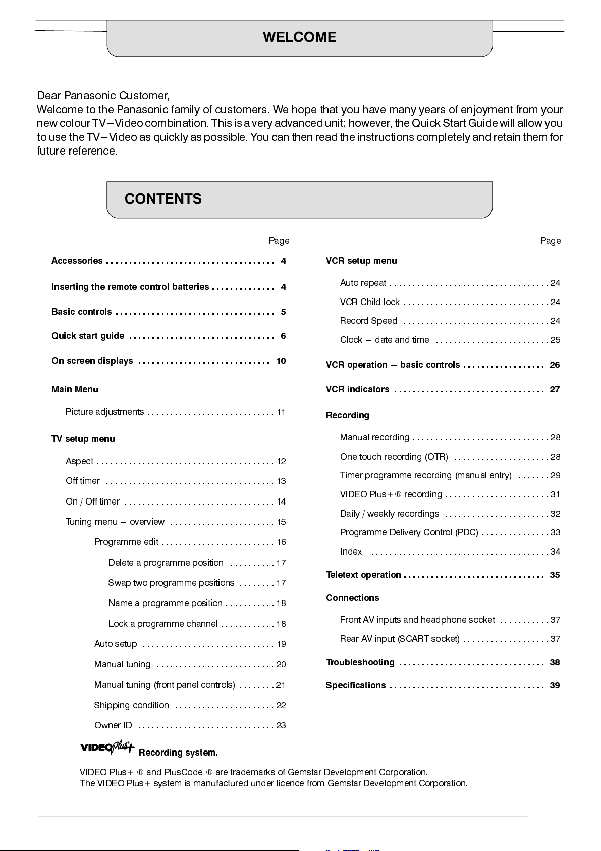
Check that you have the accessories and items shown
Operating Instruction book
TQB8E3833
TX-- 14GV2
Batteries for the Remote Control
Transmitter.
(2 x R6 (UM3) size)
Indoor antenna
CRT Guarantee
Guarantee
n
Remote Control Transmitter
EUR51941
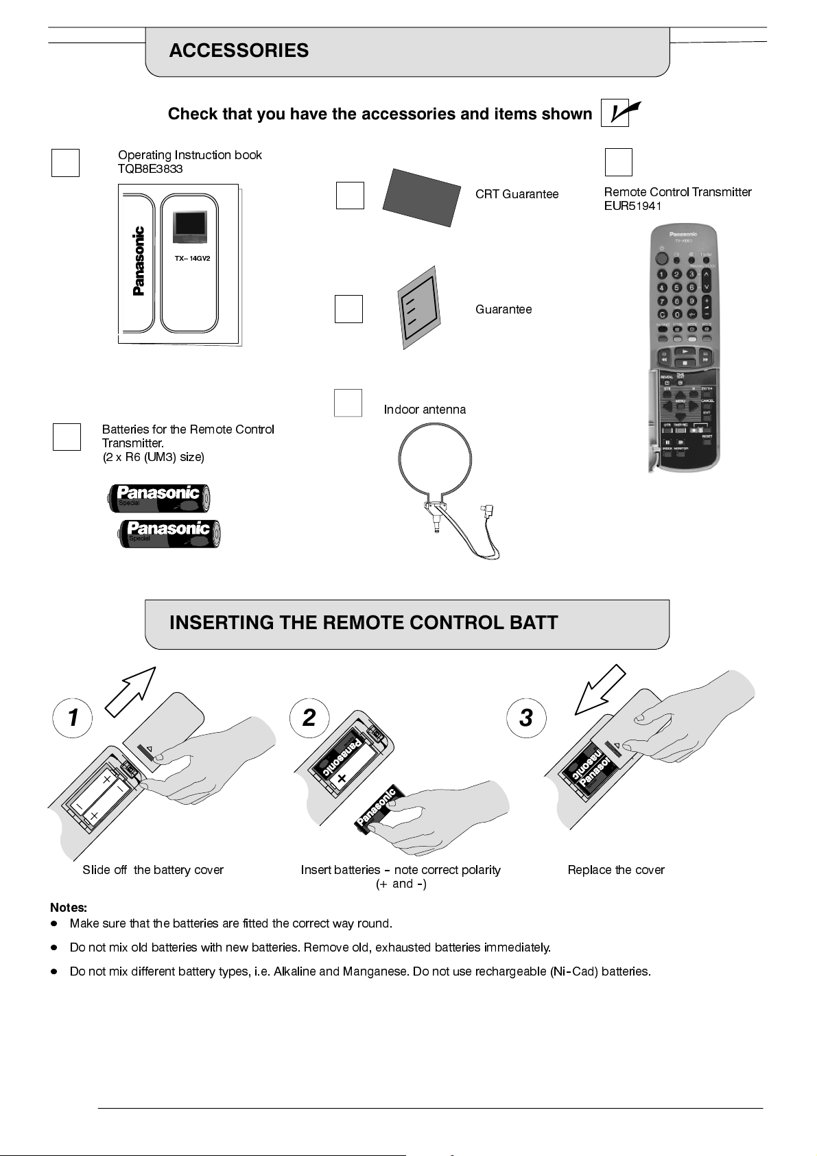
INSERTING THE REMOTE CONTROL BATTERIES
1 2 3
Slide off the battery cover Insert batteries--note correct polarity
(+ and--)
Notes:
D
Make sure that the batteries are fitted the correct way round.
D
Do not mix old batteries with new batteries. Remove old, exhausted batteries immediately.
D
Do not mix different battery types, i.e. Alkaline and Manganese. Do not use rechargeable (Ni--Cad) batteries.
Replace the cover
4
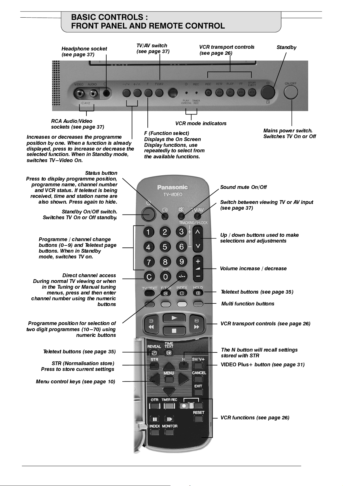
BASIC CONTROLS :
FRONT PANEL AND REMOTE CONTROL
Headphone socket
(see page 37)
RCA Audio/Video
sockets (see page 37)
Increas es or decr eases the pro gramme
position by one. When a function is already
displayed, press to increase or decrease the
selected function. When in Sta nd b y mode,
switches TV---Video On.
Status button
Press to display programm e position,
programme name, channel number
and VCR status. If teletext is being
received, time and station name are
also shown. Press again to hide.
Standby On/Off switch.
Switches TV On or Off standby.
TV/AV switch
(see page 37)
VCR mode indicators
F (Function select)
Displays the On Screen
Display functions, use
repeatedly to select from
the available functions.
VCR transport controls
(see page 26)
Sound mut e On/Off
Switch between viewing TV or AV input
(see page 37)
Standby
Mains power switch.
Switches TV On or Off
Programme / channel change
buttons (0---9) and T eletext page
buttons. When in Standby
mode, swi tches TV on.
Direct channel access
During norma l TV v iewing or when
in the Tuning or Manual tuning
menus, press and then enter
channel number using the numeric
buttons
Programme position for selection of
two digit progra m m es (10 ---70) using
numeric butt ons
Teletext buttons (see page 35)
STR (Norm a lisa t ion store)
Press to store current settings
Menu control keys (see page 10)
Up / down b ut t ons used t o make
selections and adjustments
Volume increase / d ecrease
Teletext buttons (see page 35)
Multi function buttons
VCR transport controls (see page 26)
The N button will recall settings
stored with STR
VIDEO Plus
+ button (see page 31)
VCR functions (see page 26)
5
QUICK START GUIDE
Connection and setting up options
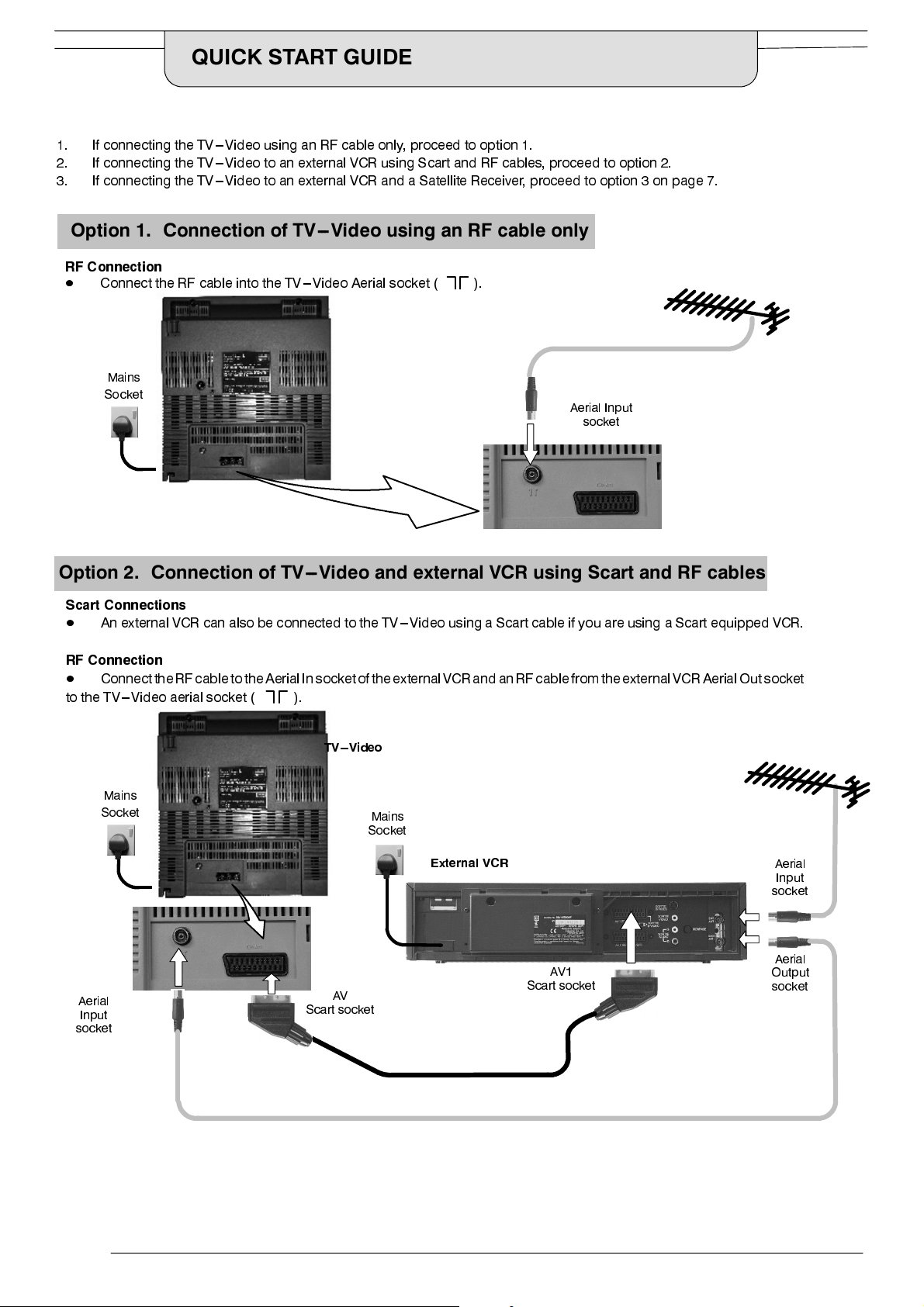
1. If connecting the TV---Video using an RF cable only, proceed to option 1.
2. If connecting the TV---Video to an external VCR using Scart and RF cables, proceed to option 2.
3. If connecting the TV---Video to an external VCR and a Satellite Receiver, proceed to option 3 on page 7.
Option 1. Connection of TV---Video using an RF cable only
RF Connection
D
Connect the RF cable into the TV---Video Aerial socket ( ).
Mains
Socket
Aerial Input
socket
Option 2. Connection of TV---Video and external VCR using Scart and RF cables
Scart Connections
D
An external VCR can alsobe connected to the TV---Video using a Scart cable if you are using a Scart equipped VCR.
RF Connection
D
ConnecttheRF cable to theAerialIn socket of theexternalVCR and anRF cable from theexternalVCR AerialOut socket
to the TV---Video aerial socket ( ).
TV --- Video
Mains
Aerial
Input
socket
Socket
Scart socket
AV
Mains
Socket
External VCR
AV1
Scart socket
Aerial
Input
socket
Aerial
Output
socket
6
QUICK START GUIDE
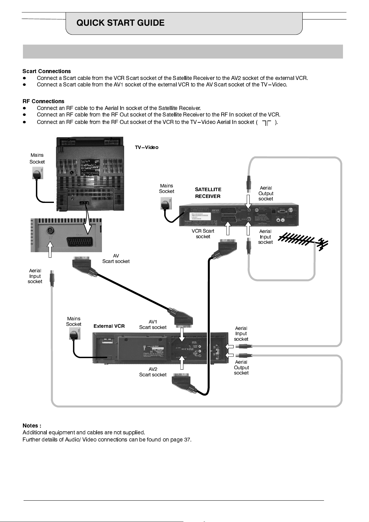
Option 3. Connection of TV ---Video, VCR and Satellite Receiver using Scart and RF cables
Scart Connections
D
Connect a Scart cable from the VCR Scart socket of the Satellite Receiver to the AV2 socket of the external VCR.
D
Connect a Scart cable from the AV1 socket of the external VCR to the AV Scart socket of the TV---Video.
RF Connections
D
Connect an RF cable to the Aerial In socket of the Satellite Receiver.
D
Connect an RF cable from the RF Out socket of the Satellite Receiver to the RF In socket of the VCR.
D
Connect an RF cable from the RF Out socket of the VCR to the TV---Video Aerial In socket (
TV --- Video
Mains
Socket
).
Aerial
Input
socket
Mains
Socket
AV
Scart socket
External VCR
Mains
Socket
AV1
Scart socket
AV2
Scart socket
SATELLITE
RECEIVER
VCR Scart
socket
Aerial
Output
socket
Aerial
Input
socket
Aerial
Input
socket
Aerial
Output
socket
Notes :
Additional equipment and cables are not supplied.
Further details of Audio/ Video connections can be found on page 37.
7
QUICK START GUIDE
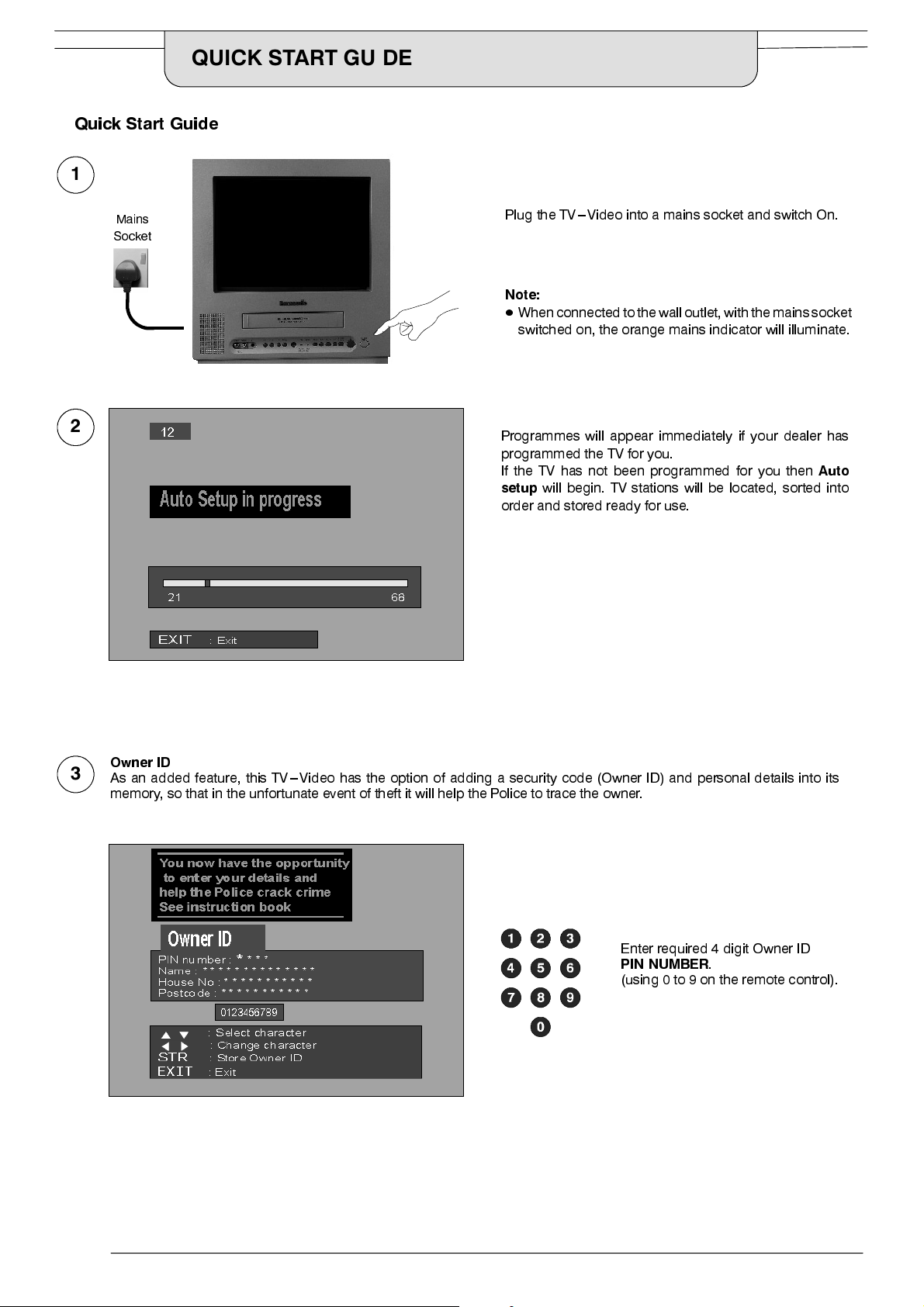
QuickStart Guide
1
Mains
Socket
2
Plug the TV---Video into a mains socket and switch On.
Note:
D
When connected to thewalloutlet,with the mainssocket
switched on, the orange mains indicator will illuminate.
Programmes will appear immediately if your dealer has
programmed the TV for you.
If the TV has not been programmed for you then
setup
will begin. TV stations will be located, sorted into
order and stored ready for use.
Auto
Owner ID
3
As an added feature, this TV---Video has the option of adding a security code (Owner ID) and personal details into its
memory, so that in the unfortunate event of theft it will help the Police to trace the owner.
Enter required 4 digit Owner ID
PIN NUMBER
(using 0 to 9 on the remote control).
.
8
QUICK START GUIDE
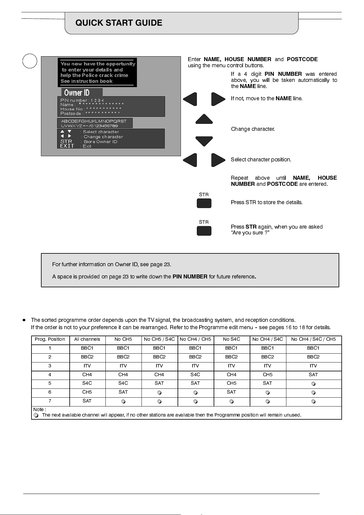
Enter
4
NAME, HOUSE NUMBER
using the menu control buttons.
If a 4 digit
above, you will be taken automatically to
the
NAME
and
PIN NUMBER
line.
POSTCODE
was entered
For further information on Owner ID, see page 23.
STR
STR
If not, move to the
NAME
line.
Change character.
Select character position.
Repeat above until
NUMBER
and
POSTCODE
NAME, HOUSE
Press STR to store the details.
Press
STR
again, when you are asked
“Are you sure ?”
are entered.
A space is provided on page 23 to write down the
D
The sorted programme order depends upon the TV signal, the broadcasting system, and reception conditions.
PIN NUMBER
for future reference
.
If the order is not to your preference it can be rearranged. Refer to the Programme edit menu--see pages 16 to 18 for details.
Prog. Position All channels No CH5 No CH5 / S4C No CH4 / CH5 No S4C No CH4 / S4C No CH4 / S4C / CH5
1 BBC1 BBC1 BBC1 BBC1 BBC1 BBC1 BBC1
2 BBC2 BBC2 BBC2 BBC2 BBC2 BBC2 BBC2
3 ITV ITV ITV ITV ITV ITV ITV
4 CH4 CH4 CH4 S4C CH4 CH5 SAT
5 S4C S4C SAT SAT CH5 SA T
6 CH5 SA T
7 SAT
Note :
~
The next available channel will appear, if no other stations are available then the Programme position will remain unused.
~ ~ ~ ~ ~ ~
~ ~
SAT
~ ~
~
9
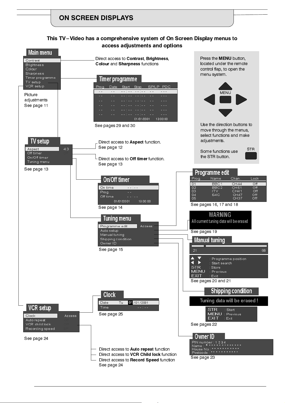
ON SCREEN DISPLAYS
This TV--Video has a comprehensive system of On Screen Display menus to
access adjustments and options
Picture
adjustments
See page 11
See page 13
Direct access to
Colour
See pages 29 and 30
and
Direct access to
See page 12
Direct access to
See page 13
Contrast,Brightness
Sharpness
Aspect
Off timer
functions
function.
function.
,
Press the
located under the remote
control flap, to open the
menu system.
Use the direction buttons to
move through the menus,
select functions and make
adjustments.
Some functions use
the STR button.
MENU
MENU
button,
STR
See page 24
See page 14
See page 15
See page 25
See pages 16, 17 and 18
See pages 19
See pages 20 and 21
See pages 22
10
Direct access to
Direct access to
Direct access to
See page 24
Auto repeat
VCR Child lock
Record Speed
function
function
function
See page 23
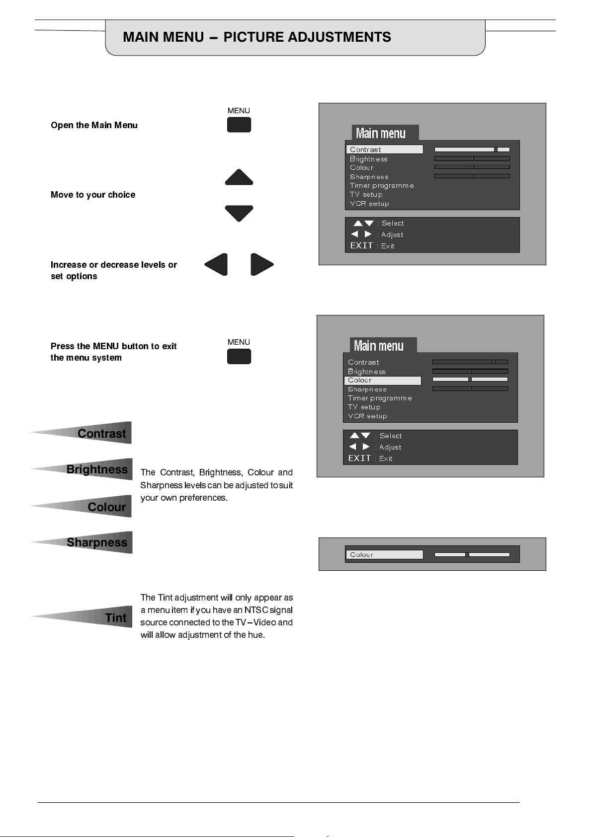
MAIN MENU --- PICTURE ADJUSTMENTS
Open the Main Menu
Move to your choice
Increase or decrease levels or
set options
MENU
Press the MENU button to exit
the menu system
Contrast
Brightness
The Contrast, Brightness, Colour and
Sharpnesslevelscan be adjustedtosuit
your own preferences.
Colour
Sharpness
The Tint adjustment will only appear as
Tint
a menuitem if you have anNTSC signal
sourceconnected tothe TV---Video and
will allow adjustment of the hue.
MENU
11
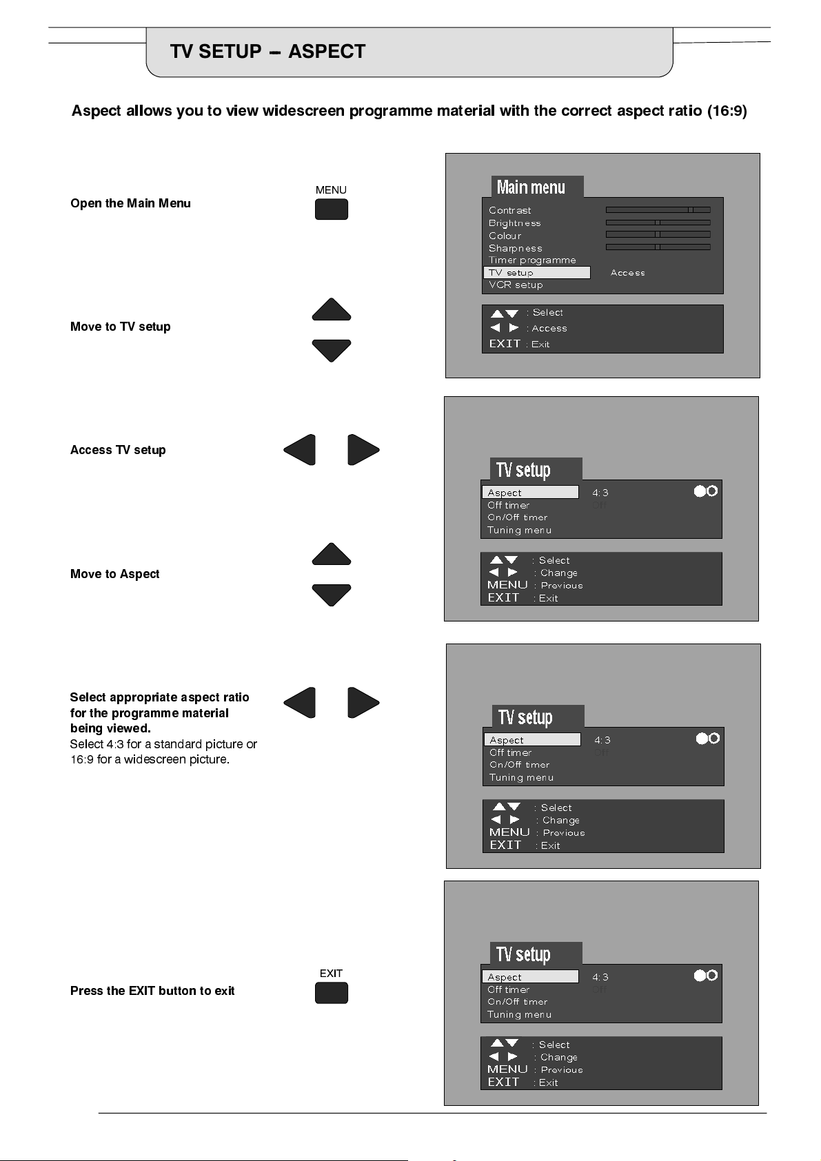
TV SETUP --- ASPECT
Aspect allows you to view widescreen programme material with the correct aspect ratio (16:9)
MENU
Open the Main Menu
Move to TV setup
Access TV setup
Move to Aspect
Select appropriate aspect ratio
for the programme material
being viewed.
Select 4:3 for a standard picture or
16:9 for a widescreen picture.
Press the EXIT button to exit
EXIT
12
 Loading...