

Panasonic TX 14B4T-B, TX-14B4T, TX-14B4TL, TC-14B4R, TC-14B4R-B Service Manual

ORDER No. SM-02008
Colour Television
TX-14B4T
TX-14B4T/B
TX-14B4TL
TC-14B4R
TC-14B4R/B
SPECIFICATIONS
Power Source: 220-240V a.c., 50Hz
Power Consumption: 39W
Stand-by Power
Consumption: 2.9W
Aerial Impedance: 75Ω unbalanced, Coaxial Type
Receiving System: PAL I, PAL-525/60
M.NTSC
NTSC (AV only)
Receiving Channels: UHF E21-E68
CH01-CH99 (L (IRISH) MODELS)
Intermediate Frequency:
Video/Audio
Video 39.5MHz
Audio 33.5MHz
32.95MHz (NICAM)
Colour 35.07MHz (PAL)
Terminals:
AV1 IN Video (21 pin)1V p-p 75Ω
Audio (21 pin) 500mV rms 10kΩ
RGB (21 pin)
Audio (RCA x 1) 500mV rms 10kΩ
Video (RCA x 1) 1V p-p 75Ω
Z-185 Chassis
AV1 OUT Video (21 pin) 1V p-p 75Ω
Audio (21 pin) 500mV rms 1kΩ
Picture Tube:
High Voltage: 26.5
Audio Output: 2.5W
(Music Power) 8Ω Impedance
Headphones: 8Ω Impedance
Accessories
supplied : Remote Control
Dimensions:
Height: 342mm
Width: 366mm
Depth: 376mm
Net weight: 9.6kg
Specifications are subject to change without notice.
Weights and dimensions shown are approximate.
A34EAC01X06 34cm
± 1kV
3.5mm
2 x R6 (UM3) Batteries
CONTENTS
SAFETY PRECAUTIONS..........................................................................................................................................................2
SERVICE HINTS.......................................................................................................................................................................3
ALIGNMENT PROCEDURE AND OPTION SETTINGS............................................................................................................4
WAVEFORM PATTERN TABLE...............................................................................................................................................5
BLOCK DIAGRAMS..................................................................................................................................................................6
PARTS LOCATION...................................................................................................................................................................7
REPLACEMENT PARTS LIST..................................................................................................................................................8
SCHEMATIC DIAGRAMS.......................................................................................................................................................14
CONDUCTOR VIEWS.............................................................................................................................................................16
SAFETY PRECAUTIONS
GENERAL GUIDE LINES
1. It is advisable to insert an isolation transformer in the
a.c. supply before servicing a hot chassis.
2. When servicing, observe the original lead dress in the
high voltage circuits. If a short circuit is found, replace
all parts that have been overheated or damaged by
the short circuit.
3. After servicing, see that all the protective devices
such as insulation barriers, insulation papers, shields
and isolation R-C combinations are correctly
installed.
4. When the receiver is not being used for a long period
of time, unplug the power cord from the a.c. outlet.
5. Potentials as high as 27.5kV are present when this
receiver is in operation. Operation of the receiver
without the rear cover involves the danger of a shock
hazard from the receiver power supply. Servicing
should not be attempted by anyone who is not
familiar with the precautions necessary when working
on high voltage equipment. Always discharge the
anode of the tube.
6. After servicing make the following leakage current
checks to prevent the customer from being exposed
to shock hazard.
LEAKAGE CURRENT COLD CHECK
1. Unplug the a.c. cord and connect a jumper between
the two prongs of the plug.
2. Turn on the receiver’s power switch.
3. Measure the resistance value with an ohmmeter,
between the jumpered a.c. plug and each exposed
metallic cabinet part on the receiver, such as screw
heads, aerials, connectors, control shafts etc. When
the exposed metallic part has a return path to the
chassis, the reading should be between 4M ohm and
20M ohm. When the exposed metal does not have a
return path to the chassis, the reading must be
infinite.
LEAKAGE CURRENT HOT CHECK
1. Plug the a.c. cord directly into the a.c. outlet. Do not
use an isolation transformer for this check.
2. Connect a 2kΩ 10W resistor in series with an
exposed metallic part on the receiver and an earth,
such as a water pipe.
3. Use an a.c. voltmeter with high impedance to
measure the potential across the resistor.
4. Check each exposed metallic part and check the
voltage at each point.
5. Reverse the a.c. plug at the outlet and repeat each of
the above measurements.
6. The potential at any point should not exceed
1.4V rms. In case a measurement is outside the limits
specified, there is a possibility of a shock hazard, and
the receiver should be repaired and rechecked before
it is returned to the customer.
X-RADIATION WARNING
1. The potential sources of X-Radiation in TV sets are
the high voltage section and the picture tube.
2. When using a picture tube test jig for service, ensure
that the jig is capable of handling 27.5kV without
causing X-Radiation.
NOTE: It is important to use an accurate periodically
calibrated high voltage meter.
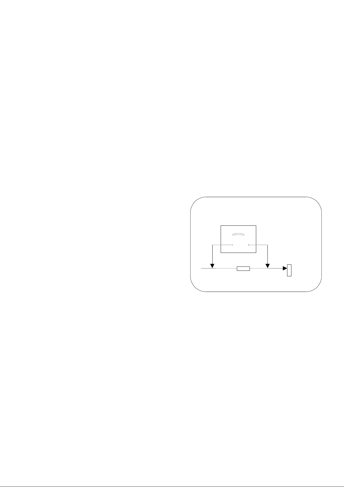
HOT CHECK CIRCUIT
a.c. VOLTMETER
2kΩ 10 Watts
TO INSTRUMENT’S EXPOSED
METALLIC PARTS
1. Set the brightness to minimum.
2. Measure the high voltage. The meter should indicate
26.5kV ± 1kV.
If the meter indication is out of tolerance, immediate
service and correction is required to prevent the
possibility of premature component failure.
3. To prevent any X-Radiation possibility, it is essential
to use the specified tube.
Fig. 1.
WATER PIPE
(
EARTH)
2
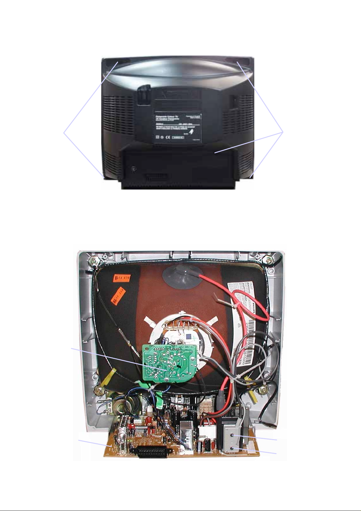
SERVICE HINTS
How to remove the rear cover
1. Remove the 10 screws as shown in Fig.2.
SCREWS
LOCATION OF CONTROLS
SCREWS
Fig.2.
Y-Board
E-Board
Focus
Screen
Fig.3.
3
ALIGNMENT PROCEDURE AND OPTION SETTING
Entering SERVICE mode
Service mode is entered by selecting the “mute” remote key and local “down” simultaneously with the sharpness DAC set to
Minimum and programme position 99 selected.
Service mode 2 is selected by pressing the Recall remote key while in service mode 1.
Service mode navigation
- Up /Down remote keys :cycle through the service items available.
- -/+ remote keys :Decrement/Increment the values within range.
- TV/AV :Store the current data.
- 0 – 7 digit keys :Toggle bits 0-7 in option byte (service mode 2).
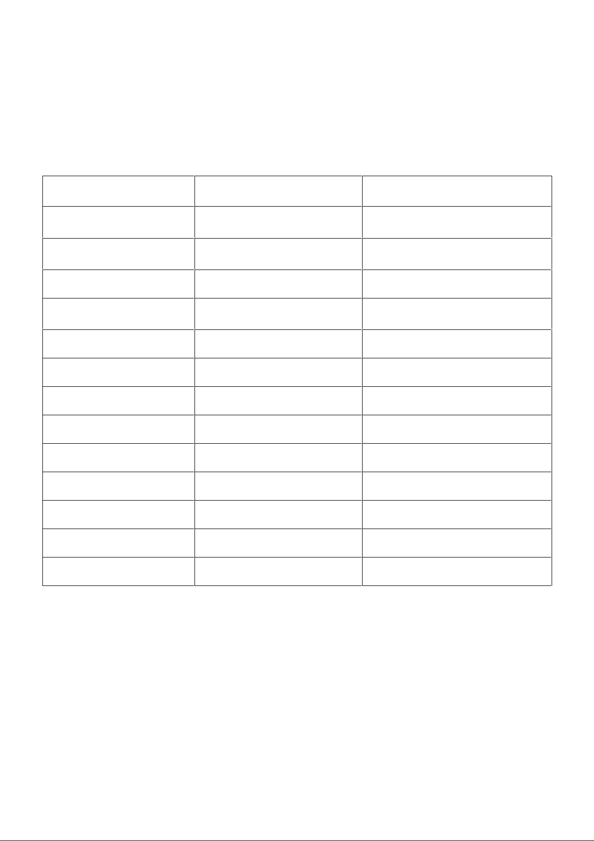
Order
1
2
3 Vertical Shift 0-63
4 Vertical amplitude 0-63
5 Horizontal shift 0-63
6 Red Cut 0-63
7 Green Cut 0-63
8 Red Drive 0-63
9 Green Drive 0-63
Item
Cut off (VG2)
Vertical slope
LED ON , LED OFF
Range
0-63
10 Blue Drive 0-63
11 AGC 0-63
12 Sub-Colour 0-63
13 Sub-Brightness 0-63
Sub-Colour: Set sub-colour to 16.
Sub-Brightness: Set sub-colour to 33.
G2 alignment: Before entering into service mode, recall the nominal picture setting :remote key “N”.
From this setting, increase brightness by 11 steps and reduce sharpness to minimum.
Tune a colour bar signal on Prg 99 and enter into SVC mode. In SVC mode , select “G2” item
and press – or + remote key to control software disable vertical deflection. The user must then
adjust G2 voltage on FBT, to find the point where LED is ON. Press – or + remote key to return
to normal SVC mode.
White balance: - Select a dark picture and adjust Red Cut and Green Cut to the desired colour temperature.
- Select a bright picture, set Blue Drive to 32 and adjust Red Drive, and Green Drive to the
desired colour temperature.
4
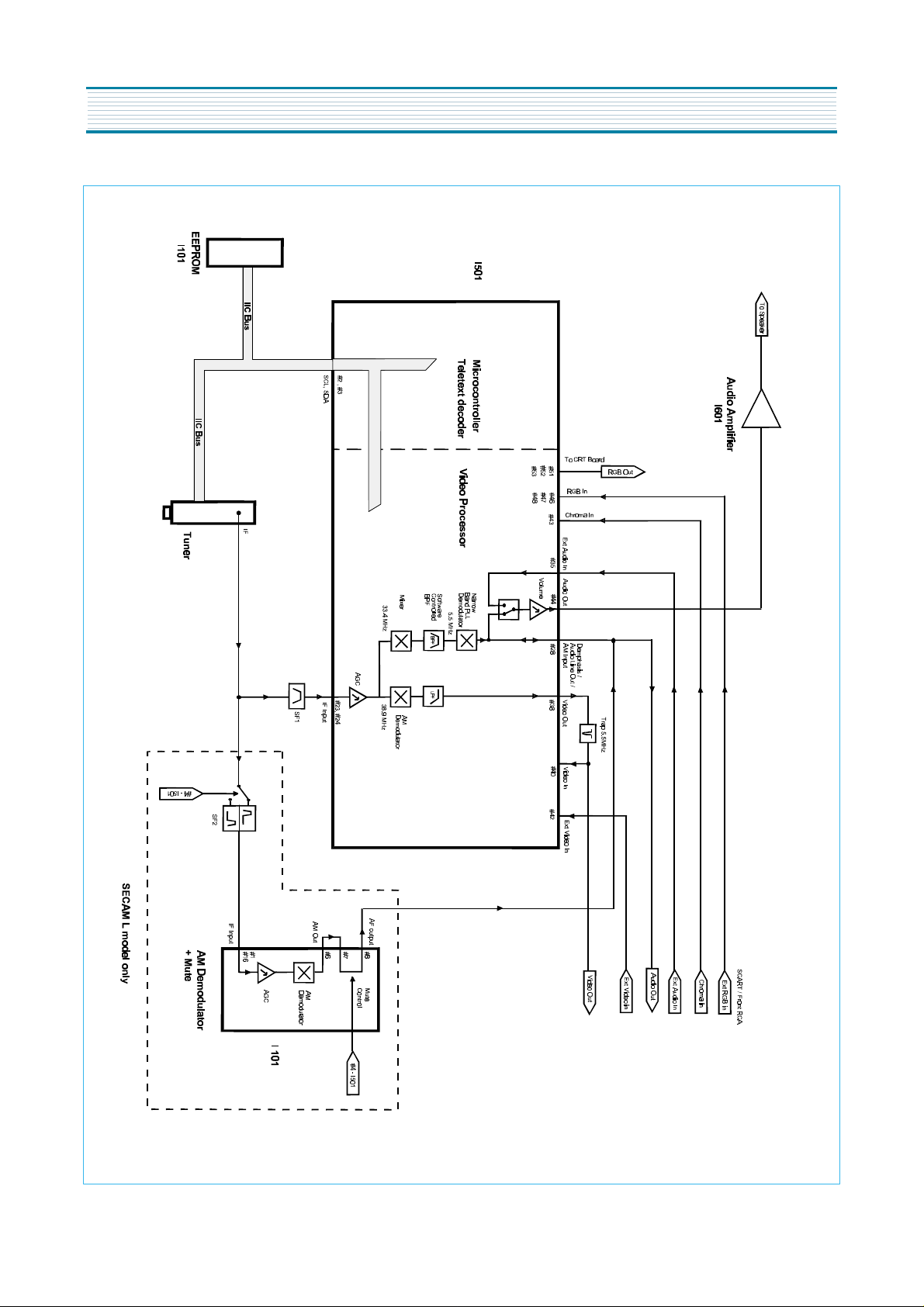
CIRCUIT BLOCK DIAGRAM
8
 Loading...