

Panasonic TH-42LFE7E, TH-42LFE7ER, TH-50LFE7U, TH-65LFE7E, TH-50LFE7E User Manual
...
Operating Instructions
FULL HD LCD Display (for business use)
Model No.
TH-42LFE7U
TH-42LFE7E
TH-50LFE7U
TH-50LFE7E
TH-65LFE7U
TH-65LFE7E
TH-42LFE7ER
English
h
Please read these instructions before operating your set
and retain them for future reference.
Dear Panasonic Customer
Welcome to the Panasonic family of customers. We hope that you will have many years of
enjoyment from your new LCD Display.
To obtain maximum benefit from your set, please read these Instructions before making
any adjustments, and retain them for future reference.
Retain your purchase receipt also, and note down the model number and serial number of
your set in the space provided on the rear cover of these instructions.
Visit our Panasonic Web Site http://panasonic.net
Table of Contents
Before use
Illustrations and screens in this Operating Instructions are images for illustration purposes, and may •
be different from the actual ones.
Descriptive illustrations in this Operating Instructions are created mainly based on the 65 inch model.
•
Important Safety Instructions .................................. 1
FCC STATEMENT ...................................................... 2
Important Safety Notice ........................................... 3
Safety Precautions ................................................... 4
Accessories .............................................................. 7
Accessories Supply ................................................. 7
Remote Control Batteries ........................................ 7
Connections .............................................................. 8
AC cord connection ................................................. 8
Video equipment connection ................................... 8
AUDIO OUT connection .......................................... 9
HDMI connection ..................................................... 9
DVI-D IN connection .............................................. 10
PC Input Terminals connection ...............................11
SERIAL Terminals connection ............................... 12
IR IN/OUT (infrared signal) connection ................. 13
CHARGE Terminals connection ............................ 13
Power On / Off ......................................................... 14
Selecting the input signal ...................................... 16
Basic Controls ........................................................ 17
ASPECT Controls ................................................... 19
Digital Zoom ............................................................ 20
On-Screen Menu Displays ..................................... 21
Adjusting Pos./Size ................................................ 22
Picture Adjustments ............................................... 24
Advanced settings ................................................. 25
Sound Adjustment .................................................. 26
PRESENT TIME Setup / Set up TIMER .................. 27
PRESENT TIME Setup .......................................... 27
Set up TIMER ........................................................ 28
Screensaver (For preventing image retention) .... 29
Setup of Screensaver Time ................................... 30
Wobbling ................................................................. 30
No activity power off .............................................. 31
ECO Mode settings ................................................. 32
Customizing the Input labels ................................. 33
Selecting the On-Screen Menu Language ............ 34
Customizing the On-Screen Menu Display .......... 34
Setup for MULTI DISPLAY ...................................... 35
How to Setup MULTI DISPLAY ............................. 35
ID Remote Control Function .................................. 36
Setup for Input Signals .......................................... 37
YUV / RGB-IN select ............................................. 37
Signal menu .......................................................... 38
Cinema reality ....................................................... 38
XGA Mode ............................................................. 39
Sync ...................................................................... 39
HDMI Range .......................................................... 40
Input signal display ................................................ 40
Network Setup ........................................................ 41
Options Adjustments ............................................. 43
Input Search .......................................................... 45
RS-232C/LAN Information Timing ......................... 46
Using Network Function ........................................ 47
Network Connection .............................................. 47
Command Control ................................................. 48
PJLink™ Protocol .................................................. 48
Using Web Browser Control .................................. 49
Before Using Web Browser Control....................... 49
Access from Web Browser .................................... 49
Display Control (BASIC CONTROL/OPTION
CONTROL Screen) ............................................... 50
NETWORK SETTING (NETWORK SETTING Screen)
Password Setting (CHANGE PASSWORD Screen) ....51
Crestron Connected™ page .................................. 52
Troubleshooting ..................................................... 54
Applicable input signals ........................................ 55
Shipping condition ................................................. 56
Speci¿ cations ......................................................... 57
... 51
ii
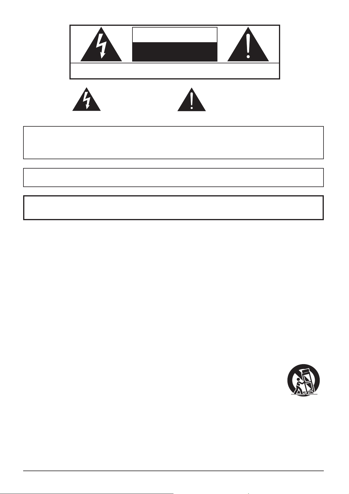
CAUTION
RISK OF ELECTRIC SHOCK
DO NOT OPEN
WARNING: To reduce the risk of electric shock, do not remove cover or back.
No user-serviceable parts inside. Refer servicing to quali¿ ed service personnel.
The lightning flash with
arrow-head within a triangle
is in tend ed to tell the user
that parts inside the product
are a risk of electric shock
to per sons.
WARNING : To prevent damage which may result in ¿ re or shock hazard, do not expose this apparatus to
rain or mois ture.
Do not place containers with water (À ower vase, cups, cosmetics, etc.) above the set.
(including on shelves above, etc.)
WARNING : To prevent electric shock, do not remove cover. No user serviceable parts inside. Refer servicing to
quali¿ ed service personnel.
The exclamation point within
a triangle is intended to
tell the user that important
operating and servicing
instructions are in the papers
with the ap pli ance.
Important Safety Instructions
1) Read these instructions.
2) Keep these instructions.
3) Heed all warnings.
4) Follow all instructions.
5) Do not use this apparatus near water.
6) Clean only with dry cloth.
7) Do not block any ventilation openings. Install in accordance with the manufacturer’s instructions.
8) Do not install near any heat sources such as radiators, heat registers, stoves, or other apparatus (including
ampli¿ ers) that produce heat.
9) Do not defeat the safety purpose of the polarized or grounding-type plug. A polarized plug has two blades with
one wider than the other. A grounding type plug has two blades and a third grounding prong. The wide blade
or the third prong are provided for your safety. If the provided plug does not ¿ t into your outlet, consult an
electrician for replacement of the obsolete outlet.
10) Protect the power cord from being walked on or pinched particularly at plugs, convenience receptacles, and
the point where they exit from the apparatus.
11) Only use attachments / accessories speci¿ ed by the manufacturer.
12) Use only with the cart, stand, tripod, bracket, or table speci¿ ed by the manufacturer, or sold
with the apparatus. When a cart is used, use caution when moving the cart / apparatus
combination to avoid injury from tip-over.
13) Unplug this apparatus during lightning storms or when unused for long periods of time.
14) Refer all servicing to quali¿ ed service personnel. Servicing is required when the apparatus has been damaged
in any way, such as power-supply cord or plug is damaged, liquid has been spilled or objects have fallen into
the apparatus, the apparatus has been exposed to rain or moisture, does not operate normally, or has been
dropped.
1
FCC STATEMENT
This equipment has been tested and found to comply with the limits for a Class B digital device, pursuant to Part
15 of the FCC Rules. These limits are designed to provide reasonable protection against harmful interference
in a residential installation. This equipment generates, uses and can radiate radio frequency energy and, if not
installed and used in accordance with the instructions, may cause harmful interference to radio communications.
However, there is no guarantee that interference will not occur in a particular installation. If this equipment does
cause harmful interference to radio or television reception, which can be determined by turning the equipment
off and on, the user is encouraged to try to correct the interference by one or more of the following measures:
• Reorient or relocate the receiving antenna.
• Increase the separation between the equipment and receiver.
• Connect the equipment into an outlet on a circuit different from that to which the receiver is connected.
• Consult the dealer or an experienced technician for help.
This device complies with Part15 of the FCC Rules. Operation is subject to the following two conditions: (1) This
device may not cause harmful interference, and (2) this device must accept any interference received, including
interference that may cause undesired operation.
FCC CAUTION:
To assure continued compliance, follow the attached installation instructions and use only shielded
interface cables when connecting to computer or peripheral devices. Any changes or modi¿ cations not
expressly approved by Panasonic Corp. of North America could void the user’s authority to operate this
device.
FCC Declaration of Conformity
Model No. TH-42LFE7U, TH-50LFE7U, TH-65LFE7U
Responsible Party: Panasonic Corporation of North America
Two Riverfront Plaza, Newark, New Jersey 07102-5490
Contact Source: Panasonic System Communications Company of North America
1-877-655-2357
CANADIAN NOTICE:
This Class B digital apparatus complies with Canadian ICES-003.
Note:
Image retention may occur. If you display a still picture for an extended period, the image might remain on the
screen. However, it will disappear after a while.
Trademark Credits
• VGA is a trademark of International Business Machines Corporation.
• Microsoft®, Windows®, Windows Vista®, and Internet Explorer® are the registered trademarks or trademarks of
Microsoft Corporation in the United States and/or other countries.
• Macintosh, Mac, Mac OS, OS X and Safari are the trademarks of Apple Inc. registered in the United States and
other countries.
• PJLink is a pending trademark in Japan, the United States and other countries and regions.
• SVGA, XGA, SXGA and UXGA are registered trademarks of the Video Electronics Standard Association.
Even if no special notation has been made of company or product trademarks, these trademarks have been
fully respected.
• HDMI, the HDMI Logo, and High-De¿ nition Multimedia Interface are trademarks or registered trademarks of
HDMI Licensing LLC in the United States and other countries.
• RoomView, Crestron RoomView and Fusion RV are registered trademarks of Crestron Electronics, Inc, and
Crestron Connected is the trademark of Crestron Electronics, Inc.
2
Important Safety Notice
IMPORTANT: THE MOULDED PLUG
WARNING
1) To prevent damage which may result in ¿ re or shock hazard, do not expose this appliance to dripping
or splashing.
Do not place containers with water (À ower vase, cups, cosmetics, etc.) above the set. (including on
shelves above, etc.)
No naked À ame sources, such as lighted candles, should be placed on / above the set.
2) To prevent electric shock, do not remove cover. No user serviceable parts inside. Refer servicing to quali¿ ed
service personnel.
CAUTION
This appliance is intended for use in environments which are relatively free of electromagnetic ¿ elds.
Using this appliance near sources of strong electromagnetic ¿ elds or where electrical noise may overlap with the
input signals could cause the picture and sound to wobble or cause interference such as noise to appear.
To avoid the possibility of harm to this appliance, keep it away from sources of strong electromagnetic ¿ elds.
IMPORTANT INFORMATION
If a display is not positioned in a suf¿ ciently stable location, it can be potentially hazardous due to falling. Many
injuries, particularly to children, can be avoided by taking simple precautions such as:
• Using cabinets or stands recommended by the manufacturer of the display.
• Only using furniture that can safely support the display.
• Ensuring the display is not overhanging the edge of the supporting furniture.
• Not placing the display on tall furniture (for example, cupboards or bookcases) without anchoring both the furniture
and the display to a suitable support.
• Not standing the displays on cloth or other materials placed between the display and supporting furniture.
• Educating children about the dangers of climbing on furniture to reach the display or its controls.
FOR YOUR SAFETY, PLEASE READ THE FOLLOWING TEXT CAREFULLY.
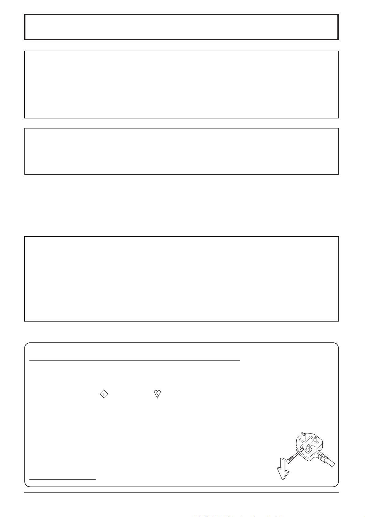
This display is supplied with a moulded three pin mains plug for your safety and convenience. A 10 amp fuse is
¿ tted in this plug. Shall the fuse need to be replaced, please ensure that the replacement fuse has a rating of 10
amps and that it is approved by ASTA or BSI to BS1362.
Check for the ASTA mark
If the plug contains a removable fuse cover, you must ensure that it is re¿ tted when the fuse is replaced.
If you lose the fuse cover the plug must not be used until a replacement cover is obtained.
A replacement fuse cover can be purchased from your local Panasonic dealer.
Do not cut off the mains plug.
Do not use any other type of mains lead except the one supplied with this display.
The supplied mains lead and moulded plug are designed to be used with this display to avoid
interference and for your safety.
If the socket outlet in your home is not suitable, get it changed by a quali¿ ed electrician.
If the plug or mains lead becomes damaged, purchase a replacement from an authorized dealer.
IMPORTANT: THE MOULDED PLUG
or the BSI mark on the body of the fuse.
ASA
How to replace the fuse.
Open the fuse compartment with a screwdriver and replace the fuse.
3

Safety Precautions
WARNING
Setup
This LCD Display is for use only with the following optional accessories. Use with any other type of optional
accessories may cause instability which could result in the possibility of injury.
(All of the following accessories are manufactured by Panasonic Corporation.)
• Pedestal ....................................................... TY-ST42PE7 (for TH-42LFE7U/E/ER, TH-50LFE7U/E)
TY-ST65PE7 (for TH-65LFE7U/E)
We are not responsible for any product damage, etc. caused by use of the pedestal or wall-hanging bracket made
by other companies, or by failures in the installation environment for the pedestal or wall-hanging bracket even
during the warranty period.
Always be sure to ask a quali¿ ed technician to carry out set-up.
Small parts can present choking hazard if accidentally swallowed. Keep small parts away from young children. Discard
unneeded small parts and other objects, including packaging materials and plastic bags/sheets to prevent them from
being played with by young children, creating the potential risk of suffocation.
Do not place the Display on sloped or unstable surfaces, and ensure that the Display does not hang over the
edge of the base.
• The Display may fall off or tip over.
Do not place any objects on top of the Display.
• If water is spills onto the Display or foreign objects get inside it, a short-circuit may occur which could result in ¿ re
or electric shock. If any foreign objects get inside the Display, please consult your local Panasonic dealer.
Transport only in upright position!
• Transporting the unit with its display panel facing upright or downward may cause damage to the internal
circuitry.
Ventilation should not be impeded by covering the ventilation openings with items such as newspapers, table
cloths and curtains.
For suf¿ cient ventilation;
Leave a space of 3 15/16” (10 cm) or more at the top, left and right, and 1 31/32” (5 cm) or more at the rear, and
also keep the space between the bottom of the display and the À oor surface.
Cautions for Wall Installation
• Wall installation should be performed by an installation professional. Installing the Display incorrectly may lead to
an accident that results in death or serious injury. Furthermore, when installing on a wall, a wall hanging bracket
that conforms to VESA standards (TH-42LFE7U/E/ER: VESA 200×200, TH-50LFE7U/E: VESA 400×200,
TH-65LFE7U/E: VESA 400×400) must be used.
• If you terminate the use of the Display on the wall, ask a professional to remove the Display as soon as possible.
• When mounting the Display on the wall, prevent the mounting screws and power cable from contacting metal objects
inside the wall. An electric shock may occur if they contact metal objects inside the wall.
When installing the Display vertically, be sure to install the power indicator onto the top of the Display.
Do not install the product to a place where the product is exposed to direct sunlight.
• If the screen is exposed to direct sunlight, the liquid crystal panel may have adverse effect.
During installation, impacts and the like may damage the Display. Please handle with care.
4

Safety Precautions
When using the LCD Display
The Display is designed to operate on 110 - 127 or 220 - 240 V AC, 50/60 Hz.
Do not cover the ventilation holes.
• Doing so may cause the Display to overheat, which can cause ¿ re or damage to the Display.
Do not stick any foreign objects into the Display.
• Do not insert any metal or À ammable objects into the ventilations holes or drop them onto the Display, as doing so
can cause ¿ re or electric shock.
Do not remove the cover or modify it in any way.
• High voltages which can cause severe electric shocks are present inside the Display. For any inspection, adjustment
and repair work, please contact your local Panasonic dealer.
Ensure that the mains plug is easily accessible.
Do not use any power supply cord other than that provided with this unit.
• Doing so may cause ¿ re or electric shocks.
Securely insert the power supply plug as far as it will go.
• If the plug is not fully inserted, heat may be generated which could cause ¿ re. If the plug is damaged or the wall
socket is loose, they shall not be used.
Do not handle the power supply plug with wet hands.
• Doing so may cause electric shocks.
Do not do anything that may damage the power cable. When disconnecting the power cable, pull on the plug
body, not the cable.
• Do not damage the cable, make any modi¿ cations to it, place heavy objects on top of it, heat it, place it near any
hot objects, twist it, bend it excessively or pull it. To do so may cause ¿ re and electric shock. If the power cable is
damaged, have it repaired at your local Panasonic dealer.
Do not remove covers and NEVER modify the Display yourself
• Do not remove the rear cover as live parts are accessible when it is removed. There are no user serviceable parts
inside. (High-voltage components may cause serious electrical shock.)
• Have the Display checked, adjusted, or repaired at your local Panasonic dealer.
If the Display is not going to be used for any prolonged length of time, unplug the power supply plug from
the wall outlet.
To prevent the spread of ¿ re, keep candles or other open À ames away from this product at all times.
If problems occur during use
If a problem occurs (such as no picture or no sound), or if smoke or an abnormal odour starts to come out
from the Display, immediately unplug the power supply plug from the wall outlet.
• If you continue to use the Display in this condition, ¿ re or electric shock could result. After checking that the smoke
has stopped, contact your local Panasonic dealer so that the necessary repairs can be made. Repairing the Display
yourself is extremely dangerous, and shall never be done.
If water or foreign objects get inside the Display, if the Display is dropped, or if the cabinet becomes damages,
disconnect the power supply plug immediately.
• A short circuit may occur, which could cause ¿ re. Contact your local Panasonic dealer for any repairs that need to
be made.
5

Safety Precautions
CAUTION
When using the LCD Display
Do not bring your hands, face or objects close to the ventilation holes of the Display.
• Heated air comes out from the ventilation holes at the top of Display will be hot. Do not bring your hands or face,
or objects which cannot withstand heat, close to this port, otherwise burns or deformation could result.
Be sure to disconnect all cables before moving the Display.
• If the Display is moved while some of the cables are still connected, the cables may become damaged, and ¿ re or
electric shock could result.
Disconnect the power supply plug from the wall socket as a safety precaution before carrying out any
cleaning.
• Electric shocks can result if this is not done.
Clean the power cable regularly to prevent it becoming dusty.
• If dust built up on the power cord plug, the resultant humidity can damage the insulation, which could result in ¿ re.
Pull the power cord plug out from the wall outlet and wipe the mains lead with a dry cloth.
Do not burn or breakup batteries.
• Batteries must not be exposed to excessive heat such as sunshine, ¿ re or the like.
Cleaning and maintenance
The front of the display panel has been specially treated. Wipe the panel surface gently using only a cleaning
cloth or a soft, lint-free cloth.
• If the surface is particularly dirty, wipe with a soft, lint-free cloth which has been soaked in pure water or water in
which neutral detergent has been diluted 100 times, and then wipe it evenly with a dry cloth of the same type until
the surface is dry.
• Do not scratch or hit the surface of the panel with ¿ ngernails or other hard objects, otherwise the surface may
become damaged. Furthermore, avoid contact with volatile substances such as insect sprays, solvents and thinner,
otherwise the quality of the surface may be adversely affected.
If the cabinet becomes dirty, wipe it with a soft, dry cloth.
• If the cabinet is particularly dirty, soak the cloth in water to which a small amount of neutral detergent has been
added and then wring the cloth dry. Use this cloth to wipe the cabinet, and then wipe it dry with a dry cloth.
• Do not allow any detergent to come into direct contact with the surface of the Display. If water droplets get inside
the unit, operating problems may result.
• Avoid contact with volatile substances such as insect sprays, solvents and thinner, otherwise the quality of the
cabinet surface may be adversely affected or the coating may peel off. Furthermore, do not leave it for long periods
in contact with articles made from rubber or PVC.
Usage of a chemical cloth
• Do not use a chemical cloth for the panel surface.
• Follow the instructions for the chemical cloth to use it for the cabinet.
Notes before use
The usage environment of the liquid crystal panel may have an effect on the screen display. In addition,
depending on the viewing angle, changes in hue or irregularities in brightness may occur.
• Please note that this is a characteristic of the liquid crystal panel and not a malfunction.
6
Accessories
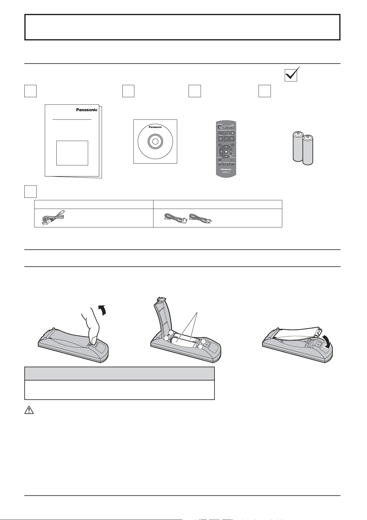
Accessories Supply
Check that you have the accessories and items shown
Operating Instruction book
Power supply cord
TH-42LFE7U, TH-50LFE7U, TH-65LFE7U TH-42LFE7E/ER, TH-50LFE7E, TH-65LFE7E
CD-ROM
(Operating
instructions)
Remote Control
Transmitter
N2QAYB000691
Attention
Store small parts in an appropriate manner, and keep them away from young children.
Remote Control Batteries
Batteries for the Remote
Control Transmitter
(R6 (UM3) Size × 2)
Requires two R6 batteries.
1. Pull and hold the hook, then open
the battery cover.
2. Insert batteries - note correct
polarity (+ and -).
“R6 (UM3)” size
-
+
+
-
3. Replace the cover.
Helpful Hint:
For frequent remote control users, replace old batteries with Alkaline
batteries for longer life.
Precaution on battery use
Incorrect installation can cause battery leakage and corrosion that will damage the remote control transmitter.
Disposal of batteries should be in an environment-friendly manner.
Observe the following precaution:
1. Batteries shall always be replaced as a pair. Always use new batteries when replacing the old set.
2. Do not combine a used battery with a new one.
3. Do not mix battery types (example: “Zinc Carbon” with “Alkaline”).
4. Do not attempt to charge, short-circuit, disassemble, heat or burn used batteries.
5.
Battery replacement is necessary when remote control acts sporadically or stops operating the Display set.
6. Do not burn or breakup batteries.
Batteries must not be exposed to excessive heat such as sunshine, ¿ re or the like.
7

Connections
AC cord connection
AC cord
(accessory)
Notes:
• Insert the AC cord ¿ rmly into place.
• When disconnecting the AC cord, be absolutely sure to disconnect the AC cord plug at the socket outlet ¿ rst.
• The included AC cord is for use with this unit only.
Video equipment connection
PC IN
PC Input Terminal
(see page 11)
IR IN/OUT
IR IN/OUT (infrared signal) Terminal
Enable connection of multiple displays.
(see page 13)
CHARGE OUT
Connect to separately sold devices such as
stick PCs to supply power. (see page 13)
SERIAL
SERIAL Input Terminal
Control the Display by connecting to PC.
(see page 12)
LAN: Connect to a network
to control the unit.
(see page 41, 47)
AUDIO IN (DVI-D / PC IN)
Connect the audio output
of a device connected to
DVI-D IN, PC IN.
(see page 10, 11)
8
DVI-D IN
DVI-D Input Terminal
(see page 10)
AV IN (HDMI 1, HDMI 2)
HDMI Input Terminal
(see page 9)
AUDIO OUT
Connect to sound equipment
(see page 9)

Connections
AUDIO OUT connection
Notes:
• Additional equipment and cables shown are not supplied with this set.
• To output sound from the AUDIO OUT terminal of the Display, be sure to set “Output Select” to “AUDIO OUT” in the
“Sound Adjustment” menu. (see page 26)
Stereophonic sound code
HDMI connection
[Pin assignments and signal names]
Pin No.
10
Signal name
1
T.M.D.S Data2+
T.M.D.S Data2
2
Shield
3
T.M.D.S Data2-
4
T.M.D.S Data1+
T.M.D.S Data1
5
Shield
6
T.M.D.S Data1-
7
T.M.D.S Data0+
T.M.D.S Data0
8
Shield
9
T.M.D.S Data0T.M.D.S Clock+
Pin No.
11
12
13
14
15
16
17
18
19
T.M.D.S Clock
Shield
T.M.D.S Clock-
CEC
Reserved
(N.C. on device)
SCL
SDA
DDC/CEC
Ground
+5V Power
Hot Plug Detect
Stereo mini plug (M3)
Signal name
audio equipment
line-in
19
3 1
HDMI cable
2
18
4
Note:
Additional equipment and HDMI cable shown are not supplied with this set.
HDMI
AV OUT
HDMI
AV OUT
DVD player
9

Connections
DVI-D IN connection
Stereo mini plug (M3)
Shared
with PC
IN.
DVI-video cable (Within 5 m)
PC with DVI-D
video out
DVI-D Input Connector
Pin Layouts
1
9
17
8
24
Connection port view
16
Pin No.
Signal Name
T.M.D.S. data 2-
1
T.M.D.S. data 2+
2
T.M.D.S. data 2 shield
3
4
5
DDC clock
6
DDC data
7
8
T.M.D.S. data 1-
9
T.M.D.S. data 1+
10
T.M.D.S. data 1 shield
11
12 24
Pin No.
13
14
15
16
17
18
19
20
21
22
23
Notes:
• Additional equipment and cables shown are not supplied with this set.
• Image deterioration may occur depending on the length or the quality of the cable.
Signal Name
+5 V DC
Ground
Hot plug detect
T.M.D.S. data 0T.M.D.S. data 0+
T.M.D.S. data 0 shield
T.M.D.S. clock shield
T.M.D.S. clock+
T.M.D.S. clock-
10

PC Input Terminals connection
Connections
(Female)
Mini D-sub 15p
(Male)
Shared with
DVI-D IN.
Stereo mini plug (M3)
Connect a cable which matches
the audio output terminal on the computer.
Conversion adapter
(if necessary)
Audio
COMPUTER
Notes:
• Computer signals which can be input are those with a horizontal scanning frequency of 30 to 110 kHz and vertical scanning
frequency of 48 to 120 Hz. (However, the image will not be displayed properly if the signals exceed 1,200 lines.)
• The display resolution is a maximum of 1,440 × 1,080 dots when the aspect mode is set to “4:3”, and 1,920 × 1,080
dots when the aspect mode is set to “16:9”. If the display resolution exceeds these maximums, it may not be possible
to show ¿ ne detail with suf¿ cient clarity.
• The PC input terminals are DDC2B-compatible. If the computer being connected is not DDC2B-compatible, you will
need to make setting changes to the computer at the time of connection.
• Some PC models cannot be connected to the set.
• There is no need to use an adapter for computers with DOS/V compatible Mini D-sub 15P terminal.
• The computer shown in the illustration is for example purposes only.
• Additional equipment and cables shown are not supplied with this set.
• Do not set the horizontal and vertical scanning frequencies for PC signals which are above or below the speci¿ ed
frequency range.
Signal Names for Mini D-sub 15P Connector
Pin No. Signal Name Pin No. Signal Name Pin No. Signal Name
1
3
4 5
2
9
10
15 14 13 12 11
6 7 8
Pin Layout for PC Input
Terminal
1
2
3
4
NC (not connected)
5
GND (Ground)
R
G
B
6
7
8
9
10
GND (Ground)
GND (Ground)
GND (Ground)
+5 V DC
GND (Ground)
11
NC (not connected)
12
13
14
15
HD/SYNC
SDA
VD
SCL
11
Connections
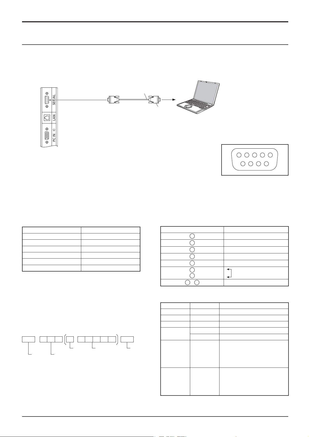
SERIAL Terminals connection
The SERIAL terminal is used when the Display is controlled by a computer.
Note:
To use serial control for this unit, make sure to set the “Control I/F Select” in the “Network Setup” menu to “RS-232C”.
(see page 41)
COMPUTER
(Male)
Notes:
• Use the RS-232C straight cable to connect the computer to the Display.
RS-232C Straight cable
(Female)
D-sub 9p
1 3 4 5 2
6 7 8 9
• The computer shown is for example purposes only.
• Additional equipment and cables shown are not supplied with this set.
Pin layout for SERIAL Terminal
The SERIAL terminal conforms to the RS-232C interface speci¿ cation, so that the Display can be controlled by a
computer which is connected to this terminal.
The computer will require software which allows the sending and receiving of control data which satis¿ es the conditions
given below. Use a computer application such as programming language software. Refer to the documentation for the
computer application for details.
Communication parameters
Signal level RS-232C compliant
Synchronization method Asynchronous
Baud rate 9600 bps
Parity None
Character length 8 bits
Stop bit 1 bit
Flow control -
Signal names for SERIAL IN terminal
Pin No. Details
2
3
4
5
6
7
8
1
9
•
(Shorted in this set)
R X D
T X D
DTR
GND
DSR
NC
These signal names are those of computer speci¿ cations.
Basic format for control data
Command
The transmission of control data from the computer
starts with a STX signal, followed by the command, the
parameters, and lastly an ETX signal in that order. If there
are no parameters, then the parameter signal does not
need to be sent.
STX C1C2C3 P1P2P3P4:P5ETX
Start
(02h)
Colon Parameter(s)
3-character
command (3 bytes)
(1 - 5 bytes)
End
(03h)
Notes:
• If multiple commands are transmitted, be sure to wait for
the response for the ¿ rst command to come from this unit
before sending the next command.
• If an incorrect command is sent by mistake, this unit will
send an “ER401” command back to the computer.
• Consult an Authorized Service Center for detail instructions
With the power off, this display responds to PON command
only.
on command usage.
12
Command Parameter Control details
PON None Power ON
POF None Power OFF
AVL *** Volume 000 - 100
AMT
IMS None
DAM None
0 Audio MUTE OFF
1 Audio MUTE ON
HM1
HM2
DV1
PC1
ZOOM
FULL
NORM
ZOM2
Input select (toggle)
HDMI 1 input (HDMI1)
HDMI 2 input (HDMI2)
DVI-D IN input (DVI)
PC IN input (PC)
Screen mode select (toggle)
Zoom1
16:9
4:3
Zoom2
Connections
IR IN/OUT (infrared signal) connection
Connect between the IR OUT terminal of the ¿ rst display and the IR IN terminal of the second display with a 3.5 mm
stereo mini plug.
Infrared signals will be sent from the ¿ rst display to the second display.
First display
* *
* Stereo mini plug (M3)
IR of the second display will not work in this connection.
It is possible to con¿ gure a daisy chain connection by repeating the connection above.
Second display
Third display
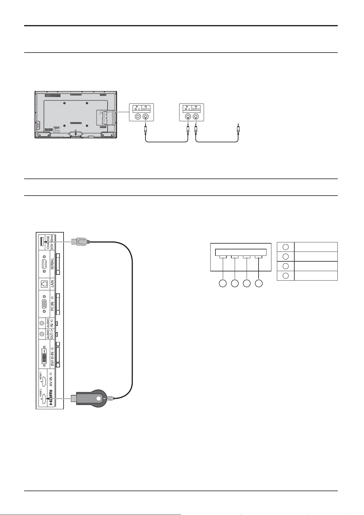
CHARGE Terminals connection
Power can be supplied when a separately sold stick PC or such other device is connected.
Note:
To supply power, be sure to set “5V Charge” to “On” in the “Options” menu. (see page 44)
Pin Layout and Signal Names of CHARGE Terminal
1
42
3
1
2
3
4
+5V
NC
NC
GND
stick PC
USB cable
Up to 5V/500 mA power can be supplied to an external device when an image is received.
Ɣ
If current exceeding the supply capacity À ows, output will be shut off and the following message will appear.
“5V CHARGE OUT overload. Please remove cable, then turn the display off/on.”
In this case, turn the power off and on with the remote control, etc.
Note:
If there is dust in a terminal, the protection circuit may function.
Cover the terminals, such as with tape, when not in use.
(The terminals are protected by tape when shipped from the factory.)
13
Power On / Off
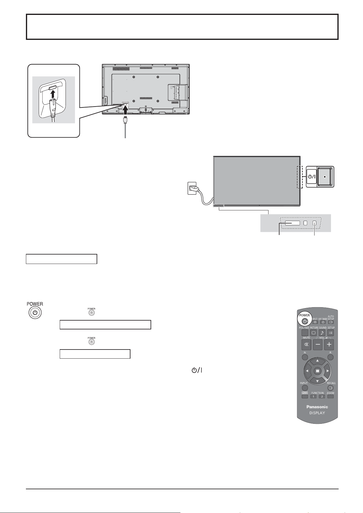
Connecting the AC cord plug to the Display.
Connecting the plug to the Wall Outlet
Notes:
• Main plug types vary between countries. The power
plug shown at right may, therefore, not be the type
¿ tted to your set.
• When disconnecting the AC cord, be absolutely
sure to disconnect the AC cord plug at the socket
outlet ¿ rst.
Power switch
Press the Power switch on the Display to turn the
set on: Power-On.
Power Indicator: Green
Press the button on the remote control to turn the Display off.
Power Indicator: Red (standby)
Press the button on the remote control to turn the Display on.
Power Indicator: Green
Turn the power to the Display off by pressing the switch on the unit, when
the Display is on or in standby mode.
Note:
During operation of the power management function, the power indicator turns
orange in the power off state.
Remote Control Sensor Power Indicator
14
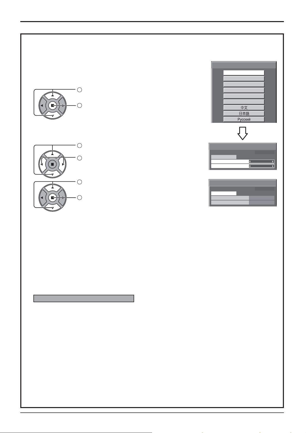
When ¿ rst switching on the unit
Following screen will be displayed when the unit is turned on for the ¿ rst time.
Select the items with the remote control. Unit buttons are invalid.
OSD Language
1
Select the language.
2
Set.
PRESENT TIME Setup
1
Select “DAY” or “PRESENT TIME”.
2
Setup “DAY” or “PRESENT TIME”.
Power On / Off
OSD Language
English (UK)
Deutsch
Français
Italiano
Español
ENGLISH (US)
PRESENT TIME Setup
PRESENT TIME MON 99 : 99
Set
DAY
PRESENT TIME
MON
99 : 99
1
Select “Set”.
2
Set.
PRESENT TIME Setup
PRESENT TIME MON 99 : 99
Set
DAY
PRESENT TIME
TUE
10 : 00
Notes:
• Once the items are set, the screens won't be displayed when switching on the unit next time.
• After the setting, the items can be changed in the following menus.
OSD Language (see page 34)
PRESENT TIME Setup (see page 27)
Power ON warning message
The following message may be displayed when turning the unit power ON:
No activity power off Precautions
’No activity power off’ is enabled.
If “No activity power off” in Setup menu is set to “Enable”, a warning message is displayed every time
the power is turned ON. (see page 31)
This message display can be set with the following menu: Options menu
Power On Message (see page 44)
15
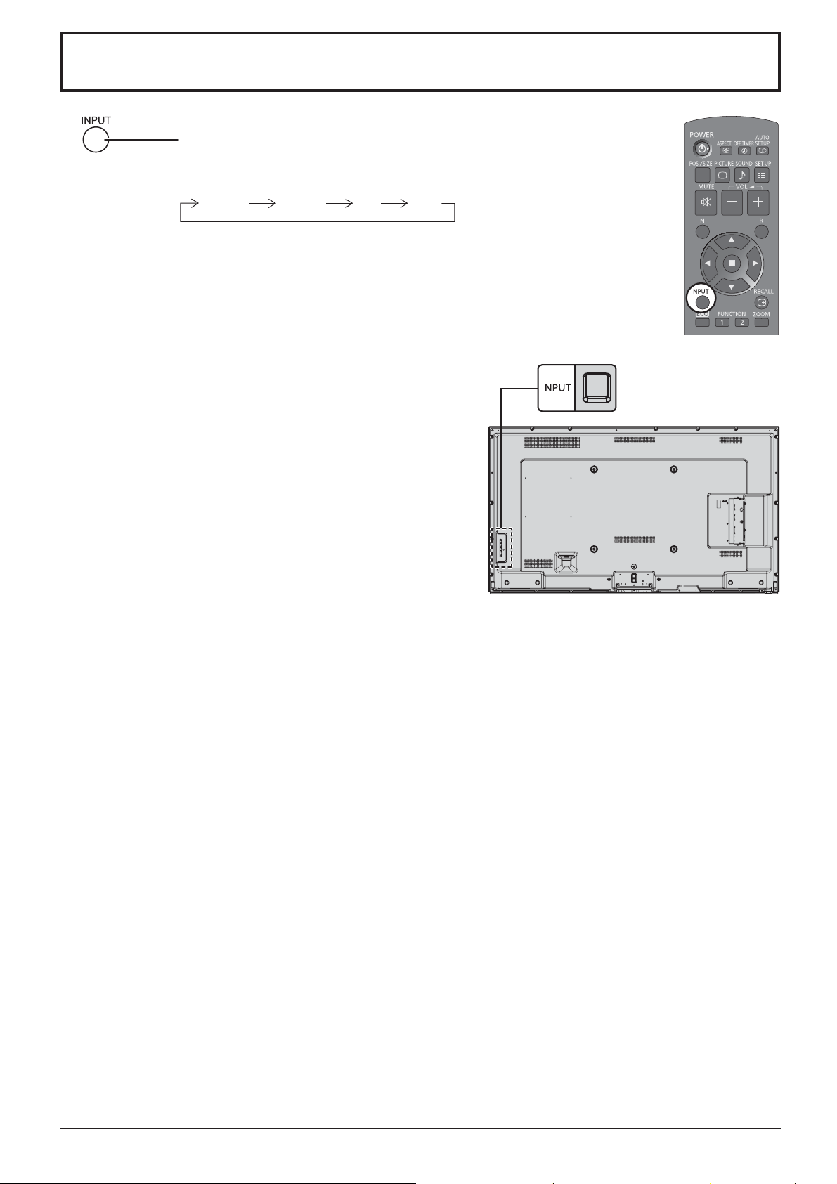
Selecting the input signal
Press to select the input signal to be played back from the equipment which
has been connected to the Display.
Input signals will change as follows:
HDMI1 HDMI2 DVIPC
HDMI1: HDMI input terminal in AV IN (HDMI1).
HDMI2: HDMI input terminal in AV IN (HDMI2).
PC: PC input terminal in PC IN.
DVI: DVI input terminal in DVI-D IN.
Note:
Selecting is also possible by pressing the INPUT button on the
unit.
1616
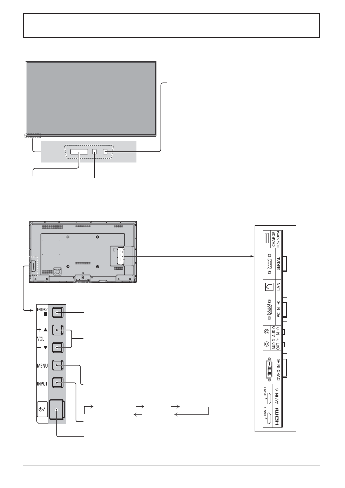
Basic Controls
Main Unit
Remote
control sensor
Brightness Sensor
Detects the brightness in the
viewing environment.
(See page 32)
Power Indicator
The Power Indicator will light.
• Power-OFF .... Indicator not illuminated (The unit will
still consume some power as long as the
power cord is still inserted into the wall
outlet.)
• Standby ......... Red
Orange (When the control terminal
selection is “LAN”. See page 41)
• Power-ON ...... Green
• HDMI1 Power management
HDMI2 Power management
......................... Orange (With HDMI1 or HDMI2 input
signal. See page 32)
• PC Power management
....................... Orange (With PC input signal.
See page 32)
• DVI-D Power management
....................... Orange (With DVI input signal.
See page 32)
External input terminals
Connects such devices as video
equipment or personal computers.
(see page 8)
Enter / Aspect button
(see page 19, 21)
Volume Adjustment
Volume Up “+” Down “–”
When the menu screen is displayed:
“+” : press to move the cursor up
“–” : press to move the cursor down
(see page 21)
MENU Screen ON / OFF
Each time the MENU button is pressed, the menu screen
will switch. (see page 21)
Normal Viewing Picture Setup
Sound Pos./Size
INPUT button (Input signal selection) (see page 16)
Main Power On / Off Switch
1717
 Loading...