

Page 1
Operating Instructions
EU
Display Operations
Touch Screen LCD Display For business use
Model No. TH-80BF1U
TH-65BF1U
TH-50BF1U
TH-80BF1E
TH-65BF1E
TH-50BF1E
TH-80BF1W
TH-65BF1W
TH-50BF1W
80-inch model
65-inch model
50-inch model
80-inch model
65-inch model
50-inch model
80-inch model
65-inch model
50-inch model
This manual is common to all the models regardless of suffixes of the model number.
*
U : for US, Canada and Mexico
E : for EU and CIS
W : for South East Asia and Middle East Asia
English
Please read these instructions before operating your set and retain
them for future reference.
DPQP1034ZD
Page 2

Dear Panasonic Customer
Welcome to the Panasonic family of customers. We hope that you will have many years of
enjoyment from your new LCD Display.
To obtain maximum benefit from your set, please read these Instructions before making any
adjustments, and retain them for future reference.
Retain your purchase receipt also, and note down the model number and serial number of your
set in the space provided on the rear cover of these instructions.
Visit our Panasonic Web Site https://panasonic.net/cns/prodisplays/
Table of Contents
Before use
Illustrations and screens in this Operating Instructions are images for illustration purposes, and may
•
be different from the actual ones.
Descriptive illustrations in this Operating Instructions are created mainly based on the 50 inch model.
•
Important Safety Instructions .................................. 1
FCC STATEMENT ...................................................... 2
Important Safety Notice ........................................... 4
Safety Precautions ................................................... 5
Precautions for use .................................................. 9
Accessories ............................................................ 11
Contents in the CD-ROM ...................................... 12
Connections ............................................................ 15
AC cord connection and fixing, cable fixing ........... 15
Video equipment connection ................................. 17
Before connecting ................................................. 19
VIDEO and COMPONENT / RGB IN connection
HDMI connection ................................................... 20
DVI-D IN connection .............................................. 21
PC Input Terminals connection .............................. 22
SERIAL Terminals connection ............................... 23
PC OUT connection............................................... 24
Example connection using the DIGITAL LINK
Terminal ................................................................. 25
Speaker connection ............................................... 26
Power On / Off ......................................................... 27
Selecting the input signal ...................................... 29
Basic Controls ........................................................ 30
ASPECT Controls ................................................... 33
Digital Zoom ............................................................ 34
MULTI PIP ................................................................ 35
Multi-touch Operation ............................................ 36
Touch Zoom ............................................................ 41
Memory Viewer Function ....................................... 42
Using Built-in WhiteBoard ..................................... 49
Using WhiteBoard Software .................................. 57
Using the Panasonic APPLICATION function ...... 58
Using the MIRRORING function ............................ 59
On-Screen Menu Displays ..................................... 60
Adjusting Pos./Size ................................................ 62
Picture Adjustments ............................................... 65
Advanced settings ................................................. 66
... 20
Picture Profiles ....................................................... 67
Saving profiles ....................................................... 68
Loading profiles ..................................................... 69
Editing profiles ....................................................... 69
Sound Adjustment .................................................. 70
SDI sound output ................................................... 70
Setup menu ............................................................. 71
Day/Time settings / On/Off timer settings ............ 72
Day/Time settings .................................................. 72
On/Off timer settings .............................................. 72
Touch screen settings ............................................ 73
MULTI PIP settings ................................................. 75
Screensaver (For preventing image retention) .... 76
Setup of Screensaver Time ................................... 77
ECO mode settings ................................................ 78
Customizing the Input labels ................................. 80
Function button settings ....................................... 81
Memory viewer settings ......................................... 82
Monitor out .............................................................. 82
No activity power off .............................................. 83
Menu display duration / OSD brightness ............. 83
OSD language ......................................................... 83
COLOR UNIVERSAL DESIGN setting ................... 84
Setup for Input Signals .......................................... 84
Component / RGB-in select ................................... 84
YUV / RGB-in select .............................................. 84
Signal menu .......................................................... 85
Options Adjustments ............................................. 88
Troubleshooting ..................................................... 96
When using MIRRORING function ........................ 98
List of Aspect Modes ........................................... 100
Preset Signals ....................................................... 102
Shipping condition ............................................... 104
Command list of Weekly command timer .......... 105
Specifications ....................................................... 106
Software License .................................................. 109
Note:
Image retention may occur. If you display a still picture for an extended period, the image might remain on the
screen. However, it will disappear after a while.
ii
Page 3
WARNING
WARNING: To reduce the risk of electric shock, do not remove cover or back.
No user-serviceable parts inside. Refer servicing to qualified service personnel.
The lightning flash with
arrow-head within a triangle
is intended to tell the user
that parts inside the product
are a risk of electric shock
to persons.
WARNING : To prevent damage which may result in fire or shock hazard, do not expose this apparatus to
rain or moisture.
Do not place containers with water (flower vase, cups, cosmetics, etc.) above the set.
(including on shelves above, etc.)
WARNING : 1) To prevent electric shock, do not remove cover. No user serviceable parts inside. Refer servicing
to qualified service personnel.
2) Do not remove the grounding pin on the power plug. This apparatus is equipped with a three pin
grounding-type power plug. This plug will only fit a grounding-type power outlet. This is a safety
feature. If you are unable to insert the plug into the outlet, contact an electrician.
Do not defeat the purpose of the grounding plug.
The exclamation point within
a triangle is intended to
tell the user that important
operating and servicing
instructions are in the
papers with the appliance.
Important Safety Instructions
1) Read these instructions.
2) Keep these instructions.
3) Heed all warnings.
4) Follow all instructions.
5) Do not use this apparatus near water.
6) Clean only with dry cloth.
7) Do not block any ventilation openings. Install in accordance with the manufacturer’s instructions.
8) Do not install near any heat sources such as radiators, heat registers, stoves, or other apparatus (including
amplifiers) that produce heat.
9) Do not defeat the safety purpose of the polarized or grounding-type plug. A polarized plug has two blades with
one wider than the other. A grounding type plug has two blades and a third grounding prong. The wide blade
or the third prong are provided for your safety. If the provided plug does not fit into your outlet, consult an
electrician for replacement of the obsolete outlet.
10) Protect the power cord from being walked on or pinched particularly at plugs, convenience receptacles, and
the point where they exit from the apparatus.
11) Only use attachments / accessories specified by the manufacturer.
12) Use only with the cart, stand, tripod, bracket, or table specified by the manufacturer, or sold
with the apparatus. When a cart is used, use caution when moving the cart / apparatus
combination to avoid injury from tip-over.
13) Unplug this apparatus during lightning storms or when unused for long periods of time.
14) Refer all servicing to qualified service personnel. Servicing is required when the apparatus has been damaged
in any way, such as power-supply cord or plug is damaged, liquid has been spilled or objects have fallen into
the apparatus, the apparatus has been exposed to rain or moisture, does not operate normally, or has been
dropped.
15) To prevent electric shock, ensure the grounding pin on the AC cord power plug is securely connected.
1
Page 4

FCC STATEMENT
This equipment has been tested and found to comply with the limits for a class A digital device, pursuant to Part
15 of the FCC Rules. These limits are designed to provide reasonable protection against harmful interference
when the equipment is operated in a commercial environment. This equipment generates, uses and can radiate
radio frequency energy and, if not installed and used in accordance with the instructions manual, may cause
harmful interference to radio communications. Operation of this equipment in a residential area is likely to cause
harmful interference in which case the user will be required to correct the interference at his own expense.
FCC CAUTION:
To assure continued compliance, follow the attached installation instructions and use only the provided
power supply cord. Any changes or modifications not expressly approved by Panasonic Corp. of North
America could void the user’s authority to operate this device.
FCC and Industry Canada (IC) RF Exposure
Warning:
This Display is provided with built-in transmitter:
•
Wireless LAN Adapter with FCC ID:
H8N-WLU5150/IC ID:1353A-WLU5150;
This transmitter complies with FCC and IC radiation exposure limits set forth for an uncontrolled
•
environment for mobile use with minimum 8 inches (20 cm) spacing requirement between transmitter
and all person’s body (excluding extremities of hands, wrist and feet) during wireless modes of
operation.
Other third-party wireless transmitters should not be used as they have not been RF exposure
•
evaluated for use with this Display and may not comply with RF exposure requirements.
<Only for wireless LAN if capable of transmission in the 5.15 ~ 5.25 GHz frequency band>
This product is restricted to indoor use due to its operation in the 5.15 to 5.25 GHz frequency range.
IC requires this product to be used indoors for the frequency range 5.15 to 5.25 GHz to reduce the potential for
harmful interference to co-channel Mobile Satellite systems. High power radars are allocated as primary users
of the 5.25 to 5.35 GHz and 5.65 to 5.85 GHz bands. These radar stations can cause interference with and/or
damage this product.
Declaration of Verification
Model No. TH-80BF1U, TH-65BF1U, TH-65BF1U
Responsible Party: Panasonic Corporation of North America
Two Riverfront Plaza, Newark, New Jersey
07102-5490
Contact Source: Panasonic System Communications Company of North America
1-877-655-2357
General Contact: http://shop.panasonic.com/support
This device complies with Part 15 of the FCC Rules and all applicable IC RSS standards. Operation is subject
to the following two conditions: (1) This device may not cause harmful interference, and (2) this device must
accept any interference received, including interference that may cause undesired operation.
2
Page 5

FCC STATEMENT
CANADIAN NOTICE:
This Class A digital apparatus complies with Canadian ICES-003.
WARNING:
Not for use in a computer room as defined in the Standard for the Protection of Electronic Computer/Data
•
Processing Equipment, ANSI/NFPA 75.
For permanently connected equipment, a readily accessible disconnect device shall be incorporated in the
•
building installation wiring.
For pluggable equipment, the socket-outlet shall be installed near the equipment and shall be easily
•
accessible.
Note:
Image retention may occur. If you display a still picture for an extended period, the image might remain on the
screen. However, it will disappear when a general moving picture is displayed for a while.
Trademark Credits
HDMI, the HDMI Logo, and High-Definition Multimedia Interface are trademarks or registered trademarks of
•
HDMI Licensing LLC in the United States and other countries.
RoomView, Crestron RoomView are registered trademarks of Crestron Electronics, Inc.
•
Crestron Connected™ and Fusion RV are trademarks of Crestron Electronics, Inc.
Wi-Fi®, Wi-Fi Direct™ and Miracast™ are registered trademarks or trademarks of Wi-Fi Alliance.
•
Windows, Windows Vista, Internet Explorer, PowerPoint, Microsoft Word and Microsoft Excel are registered
•
trademarks or trademarks of Microsoft Corporation in the United States and other countries.
Mac, Mac OS, OS X, iPad, iPhone, iPod touch and Safari are trademarks of Apple Inc., registered in the
•
United States and other countries.
iOS is a trademark and registered trademark of Cisco in the United States and other countries and is used
•
under license.
Android is a trademark of Google Inc.
•
Adobe, Adobe Flash Player and Adobe Reader are trademarks or registered trademarks of Adobe Systems
•
Inc. in the United States and/or other countries.
Intel and the Intel logo are trademarks of Intel Corporation in the U.S. and/or other countries.
•
Even if no special notation has been made of company or product trademarks, these trademarks have been
fully respected.
3
Page 6
Important Safety Notice
WARNING
1)
To prevent damage which may result in fire or shock hazard, do not expose this appliance to dripping or splashing.
Do not place containers with water (flower vase, cups, cosmetics, etc.) above the set. (including on
shelves above, etc.)
No naked flame sources, such as lighted candles, should be placed on / above the set.
2) To prevent electric shock, do not remove cover. No user serviceable parts inside. Refer servicing to qualified
service personnel.
3) Do not remove the earthing pin on the power plug. This apparatus is equipped with a three pin earthing-type
power plug. This plug will only fit an earthing-type power outlet. This is a safety feature. If you are unable to
insert the plug into the outlet, contact an electrician.
Do not defeat the purpose of the earthing plug.
4) To prevent electric shock, ensure the earthing pin on the AC cord power plug is securely connected.
CAUTION
This appliance is intended for use in environments which are relatively free of electromagnetic fields.
Using this appliance near sources of strong electromagnetic fields or where electrical noise may overlap with
the input signals could cause the picture and sound to wobble or cause interference such as noise to appear.
To avoid the possibility of harm to this appliance, keep it away from sources of strong electromagnetic fields.
WARNING:
This equipment is compliant with Class A of CISPR32. In a residential environment this equipment may cause radio interference.
IMPORTANT INFORMATION
If a display is not positioned in a sufficiently stable location, it can be potentially hazardous due to falling. Many
injuries, particularly to children, can be avoided by taking simple precautions such as:
Using cabinets or stands recommended by the manufacturer of the display.
•
Only using furniture that can safely support the display.
•
Ensuring the display is not overhanging the edge of the supporting furniture.
•
Not placing the display on tall furniture (for example, cupboards or bookcases) without anchoring both the
•
furniture and the display to a suitable support.
Not standing the displays on cloth or other materials placed between the display and supporting furniture.
•
Educating children about the dangers of climbing on furniture to reach the display or its controls.
•
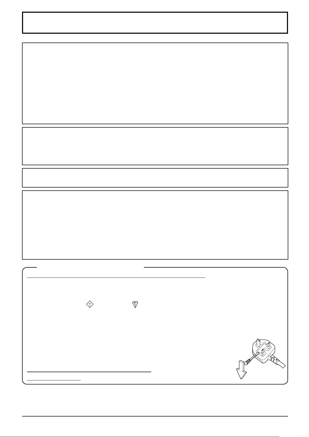
IMPORTANT: THE MOULDED PLUG
FOR YOUR SAFETY, PLEASE READ THE FOLLOWING TEXT CAREFULLY.
This display is supplied with a moulded three pin mains plug for your safety and convenience. A 10 amp fuse is
fitted in this plug. Shall the fuse need to be replaced, please ensure that the replacement fuse has a rating of
10 amps and that it is approved by ASTA or BSI to BS1362.
Check for the ASTA mark
If the plug contains a removable fuse cover, you must ensure that it is refitted when the fuse is replaced.
If you lose the fuse cover the plug must not be used until a replacement cover is obtained.
A replacement fuse cover can be purchased from your local Panasonic dealer.
Do not cut off the mains plug.
Do not use any other type of mains lead except the one supplied with this display.
The supplied mains lead and moulded plug are designed to be used with this display to
avoid interference and for your safety.
If the socket outlet in your home is not suitable, get it changed by a qualified electrician.
If the plug or mains lead becomes damaged, purchase a replacement from an authorized dealer.
WARNING : — THIS DISPLAY MUST BE EARTHED.
How to replace the fuse. Open the fuse compartment with a screwdriver and replace the fuse.
or the BSI mark on the body of the fuse.
ASA
4
Page 7
Safety Precautions
WARNING
Setup
■
This LCD Display is for use only with the following optional accessories. Use with any other type of optional
accessories may cause instability which could result in the possibility of injury.
(All of the following accessories are manufactured by Panasonic Corporation.)
1
2
*
• Pedestal ..................................................................................
• Mobile stand for Display ..........................................................
• Wall-hanging bracket (vertical) ................................................
• Wall-hanging bracket (angled) ................................................
• Ceiling-hanging bracket ..........................................................
• BNC Dual Video Terminal Board ............................................. TY-FB9BD
• HD-SDI Terminal Board ........................................................... TY-FB9HD
• HD-SDI Terminal Board with audio ......................................... TY-FB10HD
• Dual Link HD-SDI Terminal Board ........................................... TY-FB11DHD
• Dual HDMI Terminal Board ..................................................... TY-FB10HMD
• DVI-D Terminal Board ............................................................. TY-FB11DD
• Digital Interface Box ................................................................ ET-YFB100G
• DIGITAL LINK Switcher ........................................................... ET-YFB200G
• This unit does not support long reach communication method of ET-YFB200G.
• Easy wireless stick .................................................................. ET-UW100
• Early Warning Software ........................................................... ET-SWA100 series
*
1: Precaution for use of TY-ST42P50
Use a stand pole “for plasma display (long)” (part number: TBLA3679, TBLA3680).
*
2: Discontinued
*
3: This product can be purchased in the U.S., Canada, Japan, Australia and New Zealand.
*
4: Suffix of the part number may differ depending on the license type.
50-inch model
50-inch model
80-inch model 65-inch model
50-inch model
65-inch model
80-inch model
50-inch model
80-inch model
50-inch model
65-inch model
50-inch model
TY-ST42P50
TY-ST50PB2
TY-ST65PB2
TY-ST80LF70
TY-WK42PV20
TY-WK70PV50
TY-WK42PR20
TY-WK65PR20
TY-CE42PS20
2
*
2
*
3
*
4
*
*
TY-ST65P20
2
*
Note:
The part number of the optional accessories are subject to change without notice.
•
When installing the pedestal, read the operating instructions supplied with it carefully and install properly. Also,
always use the overturn prevention accessories.
When using a terminal board, read the operating instructions supplied with it carefully and use properly.
Small parts can present choking hazard if accidentally swallowed. Keep small parts away from young children.
Discard unneeded small parts and other objects, including packaging materials and plastic bags/sheets to prevent
them from being played with by young children, creating the potential risk of suffocation.
Do not place the Display on sloped or unstable surfaces, and ensure that the Display does not hang over
the edge of the base.
The Display may fall off or tip over.
•
Install this unit at a location with minimal vibration and which can support the weight of the unit.
Dropping or falling of the unit may cause injury or malfunction.
•
Do not place any objects on top of the Display.
If foreign objects or water get inside the Display, a short-circuit may occur which could result in fire or electric
•
shock. If any foreign objects get inside the Display, please consult your local Panasonic dealer.
Transport only in upright position!
Transporting the unit with its liquid crystal panel facing upright or downward may cause damage to the internal
•
circuitry.
Ventilation should not be impeded by covering the ventilation openings with items such as newspapers,
table cloths and curtains. For sufficient ventilation, see page 9.
5
Page 8

Safety Precautions
When installing the Display vertically, be sure that the Power Indicator
comes to the upper side. Heat is generated and it may cause fire or
damage to the Display.
Cautions for Wall or Pedestal Installation
The installation should be performed by an installation professional. Installing the Display incorrectly may lead to
•
an accident that results in death or serious injury. Use the optional Pedestal. (see page 5)
Before installation, be sure to check if the mounting location has enough strength to support the weight of the
•
LCD display and the wall hanging bracket for anti drop.
If you terminate the use of the Display on the Wall or Pedestal, ask a professional to remove the Display as soon
•
as possible.
When mounting the Display on the wall, prevent the mounting screws and power cable from contacting metal
•
objects inside the wall. An electric shock may occur if they contact metal objects inside the wall.
We are not responsible for any product damage, etc. caused by use of the pedestal, wall-hanging bracket or
ceiling-hanging bracket made by other companies, or by failures in the installation environment for the pedestal,
wall-hanging bracket or ceiling-hanging bracket even during the warranty period.
Power indicator
Do not install the product to a place where the product is exposed to direct sunlight.
If the screen is exposed to direct sunlight, the liquid crystal panel may have adverse effect.
•
When using the LCD Display
■
The Display is designed to operate on 110 - 127 or 220 - 240 V AC, 50/60 Hz.
Do not cover the ventilation holes.
Doing so may cause the Display to overheat, which can cause fire or damage to the Display.
•
Do not stick any foreign objects into the Display.
Do not insert any metal or flammable objects into the ventilations holes or drop them onto the Display, as doing
•
so can cause fire or electric shock.
Do not remove the cover or modify it in any way.
High voltages which can cause severe electric shocks are present inside the Display. For any inspection,
•
adjustment and repair work, please contact your local Panasonic dealer.
Ensure that the mains plug is easily accessible.
The mains plug shall be connected to a mains socket outlet with a protective earthing connection.
Do not use any power supply cord other than that provided with this unit.
Doing so may cause short-circuit, generates heat, etc., which could cause electric shock or fire.
•
Do not use the supplied power supply cord with any other devices.
Doing so could cause electric shock or fire.
•
Securely insert the power supply plug as far as it will go.
If the plug is not fully inserted, heat may be generated which could cause fire. If the plug is damaged or the wall
•
socket is loose, they shall not be used.
Do not handle the power supply plug with wet hands.
Doing so may cause electric shocks.
•
Do not do anything that may damage the power cable. When disconnecting the power cable, pull on the
plug body, not the cable.
Do not damage the cable, make any modifications to it, place heavy objects on top of it, heat it, place it near any
•
hot objects, twist it, bend it excessively or pull it. To do so may cause fire and electric shock. If the power cable is
damaged, have it repaired at your local Panasonic dealer.
Do not touch the power supply cord or the plug directly by hand when they are damaged.
Electric shock could occur.
6
Page 9
Safety Precautions
Do not remove covers and NEVER modify the Display yourself.
Do not remove the rear cover as live parts are accessible when it is removed. There are no user serviceable
•
parts inside. (High-voltage components may cause serious electrical shock.)
Have the Display checked, adjusted, or repaired at your local Panasonic dealer.
•
Keep the pen stand fixing screw and the washer (for 80-inch model only) out of reach of children. If
accidentally swallowed, it will be harmful to the body.
Please contact a doctor immediately in case you doubt that the child may have swallowed it.
•
If the Display is not going to be used for any prolonged length of time, unplug the power supply plug from
the wall outlet.
Picture noise may occur if you connect / disconnect the cables connected to the input terminals you are
currently not watching, or if you turn the power of the video equipment on / off, but it is not a malfunction.
To prevent the spread of fire, keep candles or other open flames away from this product at all times.
CAUTION
If problems or malfunction occur, stop using immediately.
If problems occur, unplug the power supply plug.
■
Smoke or an abnormal odour come out from the unit.
•
No picture appears or no sound is heard, occasionally.
•
Liquid such as water or foreign objects got inside the unit.
•
The unit has deformed or broken parts.
•
If you continue to use the unit in this condition, it could result in fire or electric shock.
Turn the power off immediately, unplug the power supply plug from the wall outlet, and then contact the dealer
•
for repairs.
To cut off the power supply to this Display completely, you need to unplug the power supply plug from the wall
•
outlet.
Repairing the unit yourself is dangerous, and shall never be done.
•
To enable to unplug the power supply plug immediately, use the wall outlet which you can reach easily.
•
Do not touch the unit directly by hand when it is damaged.
■
Electric shock could occur.
When using the LCD Display
■
Do not bring your hands, face or objects close to the ventilation holes of the Display.
Heated air comes out from the ventilation holes at the top of Display will be hot. Do not bring your hands or face,
•
or objects which cannot withstand heat, close to this port, otherwise burns or deformation could result.
Required number of people to carry or unpack this unit:
80-inch model 65-inch model
50-inch model
If this is not observed, the unit may drop, resulting in injury.
•
Be sure to disconnect all cables before moving the Display.
If the Display is moved while some of the cables are still connected, the cables may become damaged, and fire
•
or electric shock could result.
Disconnect the power supply plug from the wall socket as a safety precaution before carrying out any
cleaning.
Electric shocks can result if this is not done.
•
Clean the power cable regularly to prevent it becoming dusty.
If dust built up on the power cord plug, the resultant humidity can damage the insulation, which could result in
•
fire. Pull the power cord plug out from the wall outlet and wipe the mains lead with a dry cloth.
Do not step on, or hang from the display or the Pedestal.
They might tip over, or might be broken and it may result in injury. Pay special attention to the children.
•
Do not reverse the polarity (+ and -) of the battery when inserting.
Mishandling the battery may cause its explosion or leakage, resulting in fire, injury or damage to surrounding
•
properties.
Insert the battery correctly as instructed. (see page 12)
•
: 2 or more people
: 4 or more people
7
Page 10

Safety Precautions
Remove the batteries from the remote control transmitter when not using for a long period of time.
The battery may leak, heat, ignite or burst, resulting in fire or damage to surrounding properties.
•
Do not burn or breakup batteries.
Batteries must not be exposed to excessive heat such as sunshine, fire or the like.
•
Do not turn the Display upside down.
Do not position the unit with its display panel facing upright.
8
Page 11
Precautions for use
Cautions when installing
Do not set up the Display outdoors.
The Display is designed for indoor use.
•
Environmental temperature to use this unit
When using the unit where it is below 1 400 m (4 593 ft) above sea level: 0 °C to 40 °C (32 °F to 104 °F)
•
When using the unit at high altitudes (1 400 m (4 593 ft) and higher and below 2 800 m (9 186 ft) above sea
•
level): 0 °C to 35 °C (32 °F to 95 °F)
Do not install the unit where it is 2 800 m (9 186 ft) and higher above sea level.
Failure to do so may shorten the life of the internal parts and result in malfunctions.
•
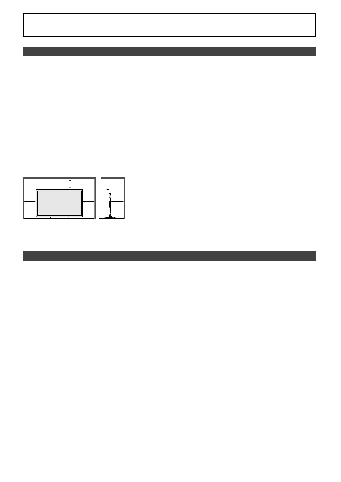
Required space for ventilation
When using the pedestal (optional accessory), leave a space of 10 cm (3
and 7 cm (2 3/4”) or more at the rear, and also keep the space between the bottom of the display and the floor
surface.
If using some other setting-up method (wall-hanging, etc.), follow the manual of it. (If there is no specific indication
of installation dimension in the installation manual, leave a space of 10 cm (3 15/16”) or more at the top, bottom, left
and right, and 7 cm (2 3/4”) or more at the rear.)
Minimum distance:
a
a
a b
a: 10 cm
(3 15/16”)
b: 7 cm
(2 3/4”)
15/16”) or more at the top, left and right,
Depending on the temperature or humidity conditions, uneven brightness may be observed. This is not a
malfunction.
This unevenness will disappear while applying current continuously. If not, consult the distributor.
•
Request Regarding Security
When using this product, take safety measures against the following incidents.
Personal information being leaked via this product
•
Unauthorized operation of this product by a malicious third party
•
Interfering or stopping of this product by a malicious third party
•
Take sufficient security measures.
Set a password for the LAN control and restrict the users who can log in.
•
Make your password difficult to guess as much as possible.
•
Change your password periodically.
•
Panasonic Corporation or its affiliate companies will never ask for your password directly. Do not divulge your
•
password in case you receive such inquiries.
The connecting network must be secured by a firewall, etc.
•
When disposing the product, initialize the data before disposing. “Shipping” (see page 104)
•
9
Page 12

Precautions for use
IR transmission part
Cleaning and maintenance
The front of the liquid crystal panel has been specially treated. Wipe the surface of the liquid crystal panel
gently using only a cleaning cloth or a soft, lint-free cloth.
If the surface is particularly dirty, wipe with a soft, lint-free cloth which has been soaked in pure water or water in
•
which neutral detergent has been diluted 100 times, and then wipe it evenly with a dry cloth of the same type until
the surface is dry.
Wipe off dirt on the IR transmission part with soft cloth.
Wipe off dirt on the IR transmission part with soft cloth once a day.
•
If malfunction is due to dirt on the IR transmission part, simply wiping it off lightly can recover the performance.
If dirt is sticky, wipe it off with cloth wrung out of neutral detergent diluted with water and then wipe the part with
dry cloth.
If the substance such as the material of the supplied pen is stuck on the glass surface, wipe it with a wet cloth.
•
Note that if a deep scratch is caused by using objects other than the supplied pen, it may not be wiped off.
Do not scratch or hit the surface of the panel with fingernails or other hard objects, otherwise the surface may
•
become damaged. Furthermore, avoid contact with volatile substances such as insect sprays, solvents and
thinner, otherwise the quality of the surface may be adversely affected.
If the cabinet becomes dirty, wipe it with a soft, dry cloth.
If the cabinet is particularly dirty, soak the cloth in water to which a small amount of neutral detergent has been
•
added and then wring the cloth dry. Use this cloth to wipe the cabinet, and then wipe it dry with a dry cloth.
Do not allow any detergent to come into direct contact with the surface of the Display. If water droplets get inside
•
the unit, operating problems may result.
Avoid contact with volatile substances such as insect sprays, solvents and thinner, otherwise the quality of the
•
cabinet surface may be adversely affected or the coating may peel off. Furthermore, do not leave it for long
periods in contact with articles made from rubber or PVC.
Usage of a chemical cloth
Do not use a chemical cloth for the panel surface.
•
Follow the instructions for the chemical cloth to use it for the cabinet.
•
Touch panel
Carefully observe the following instructions as the display has an optical touch panel.
Do not expose the display to direct sunlight or strong light source during use.
Otherwise malfunction may occur since the optical touch panel of the display uses infrared rays.
•
After turning on the power of the display, do not touch the IR transmission part and
the screen until any image is displayed.
Otherwise the touched part may be detected as defective elements, resulting in
•
abnormal operation. If this occurred, turn the display off and then on.
Always use a finger or the supplied pen to operate the touch panel. Do not use a hard or sharp tip such as
nail, ball-point pen, and pencil.
When using any other infrared device, keep a distance to prevent erroneous operation.
Disposal
When disposing the product, ask your local authority or dealer about the correct methods of disposal.
For USA-California Only
This product contains a CR Coin Cell Lithium Battery which contains Perchlorate Material - special handling may apply.
See www.dtsc.ca.gov/hazardouswaste/perchlorate
10
Page 13
Accessories
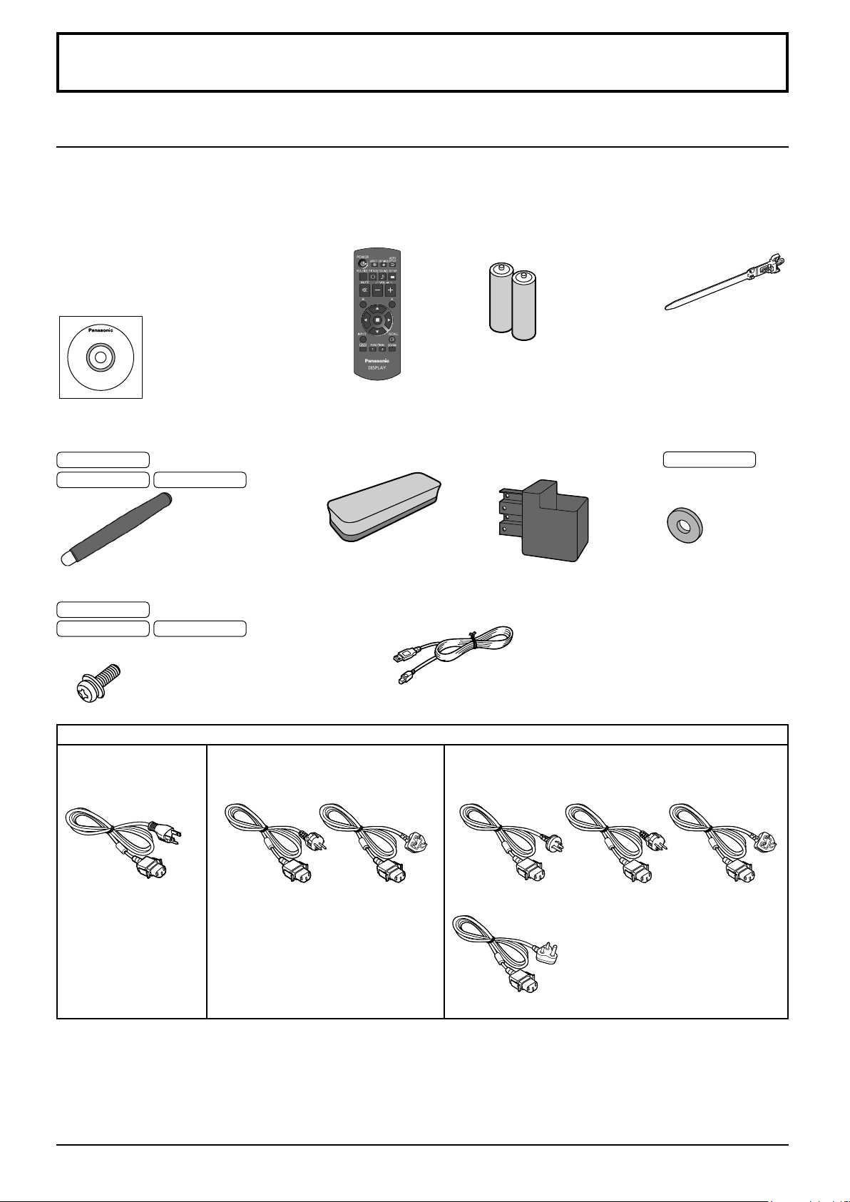
Accessories Supply
Check that you have the accessories and items shown
Software CD-ROM × 1
TH-80BF1U, TH-65BF1U, TH-50BF1U:
DPQC1006ZB
TH-80BF1E, TH-65BF1E, TH-50BF1E:
DPQC1005ZB
TH-80BF1W, TH-65BF1W, TH-50BF1W:
DPQC1007ZC
Remote Control
Transmitter
N2QAYB000691
Batteries for the Remote
Control Transmitter
(R6 (UM3) Size × 2)
Clamper × 1
TMME289
Pen
TKR5ZA45001
80-inch model
65-inch model 50-inch model
Screw × 2
80-inch model
65-inch model 50-inch model
(see page 13)
Power supply cord
TH-80BF1U
TH-65BF1U
TH-50BF1U
× 4
XYN4+F12FJK
TH-80BF1E
TH-65BF1E
TH-50BF1E
Eraser × 1
TKK5ZH50031
× 2
XYN4+F8FJK
USB cable × 1
K1HY05YY0189
TH-80BF1W
TH-65BF1W
TH-50BF1W
Pen Stand × 1
TKK5ZA50021
(see page 13)
Washer × 2
(see page 14)
80-inch model
TMM5ZX010
TXFMX011WFU
TXFMX011TFR TXFMX021TFR
TXFMX011NGW TXFMX011TFR TXFMX021TFR
TXFMX01YGFZ
Attention
Store small parts in an appropriate manner, and keep them away from young children.
•
The part numbers of accessories are subject to change without notice. (The actual part number may differ from
•
the ones shown above.)
In case you lost accessories, please purchase them from your dealer. (Available from the customer service)
•
Dispose the packaging materials appropriately after taking out the items.
•
11
Page 14
Accessories
Contents in the CD-ROM
The contents below are included in the supplied CD-ROM.
Instruction
(PDF)
Software WhiteBoard Software (Windows)
Operating Instructions - Display Operations
Operating Instructions - Network Operations
Operating Instructions - Wireless Manager ME
Software license GNU GENERAL PUBLIC LICENSE
Wireless Manager ME (Windows/Mac) Allows the image on the computer screen to
GNU LESSER GENERAL PUBLIC LICENSE
Allows the display to be used as whiteboard.
You can run the software directly from external
storage without installing it in your computer.
(see page 57)
be sent wirelessly or via wired LAN.
Switch the input to Panasonic APPLICATION
before use. For more details, see the
instruction manual of Wireless Manager ME.
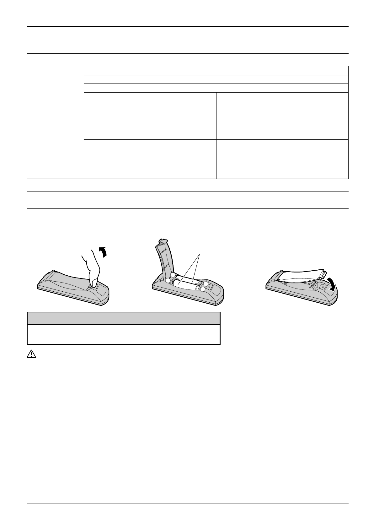
Remote Control Batteries
Requires two R6 batteries.
1. Pull and hold the hook, then open
the battery cover.
Helpful Hint:
For frequent remote control users, replace old batteries with
Alkaline batteries for longer life.
Precaution on battery use
Incorrect installation can cause battery leakage and corrosion that will damage the remote control transmitter.
Disposal of batteries should be in an environment-friendly manner.
Observe the following precaution:
1. Batteries shall always be replaced as a pair. Always use new batteries when replacing the old set.
2. Do not combine a used battery with a new one.
3. Do not mix battery types (example: “Zinc Carbon” with “Alkaline”).
4. Do not attempt to charge, short-circuit, disassemble, heat or burn used batteries.
5.
Battery replacement is necessary when remote control acts sporadically or stops operating the Display set.
6. Do not burn or breakup batteries.
7. Batteries must not be exposed to excessive heat such as sunshine, fire or the like.
2. Insert batteries - note correct
polarity (+ and -).
“R6 (UM3)” size
-
+
+
-
3. Replace the cover.
12
Page 15
Accessories
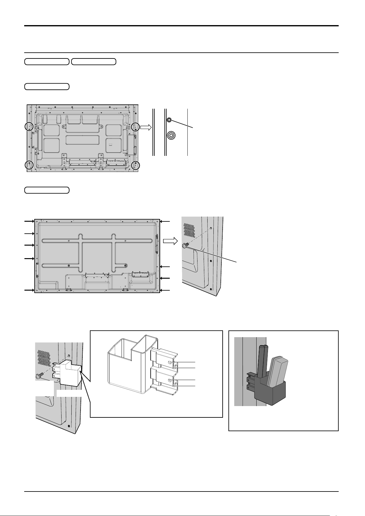
Mounting Pen Stand
50-inch model 65-inch model
Mounting position of the Pen Stand
50-inch model
The supplied Pen Stand can be mounted in one of the four dedicated screw hole positions on the back of the Display.
Each hole is marked with a circle.
65-inch model
The supplied Pen Stand can be mounted in one of the nine positions on the back of the Display.
Remove one screw fixing the back cover and mount the Pen Stand.
Mounting
Mount the Pen Stand using one supplied screw.
Screw
(supplied)
Pen Stand
Mounting on the left side: Use either A or C
Mounting on the right side: Use either B or D
Remove one screw from the back
cover.
A
B
C
D
The Pen Stand can hold 2 pens and
one Eraser.
13
Page 16
Accessories
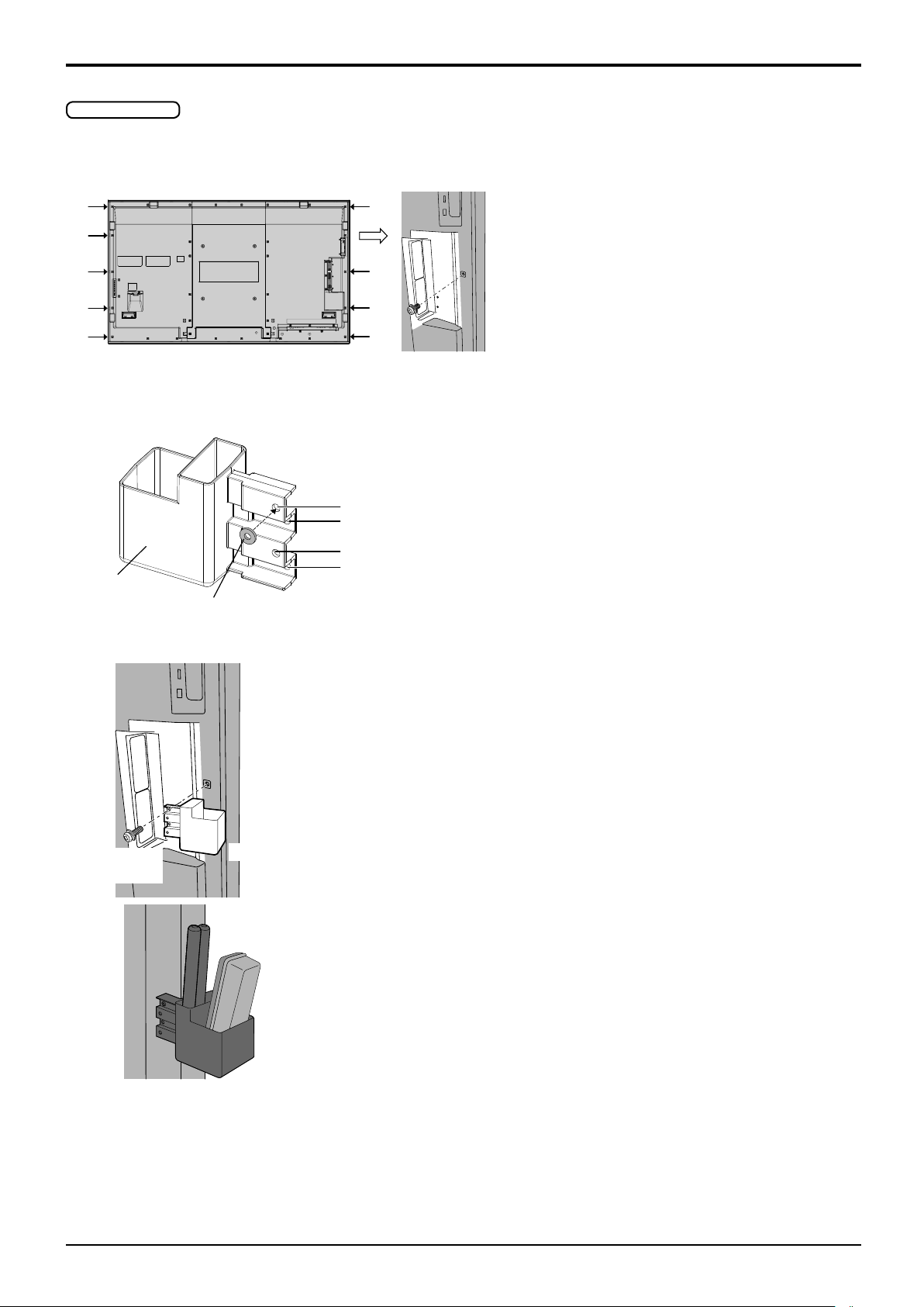
80-inch model
The supplied Pen Stand can be mounted on one of the nine positions on the back of the Display.
1 Remove a screw from the back cover.
2 Peel the paper backing off the supplied washer.
3 Paste the washer to a screw hole for the pen stand.
Any of the hole A to D can be used to fix the pen stand.
A
B
C
Pen Stand
(supplied)
4 Mount the Pen Stand with the supplied screw.
Screw
(supplied)
Washer (supplied)
Pen Stand
D
The Pen Stand can hold 2 pens and one Eraser.
14
Page 17
Connections
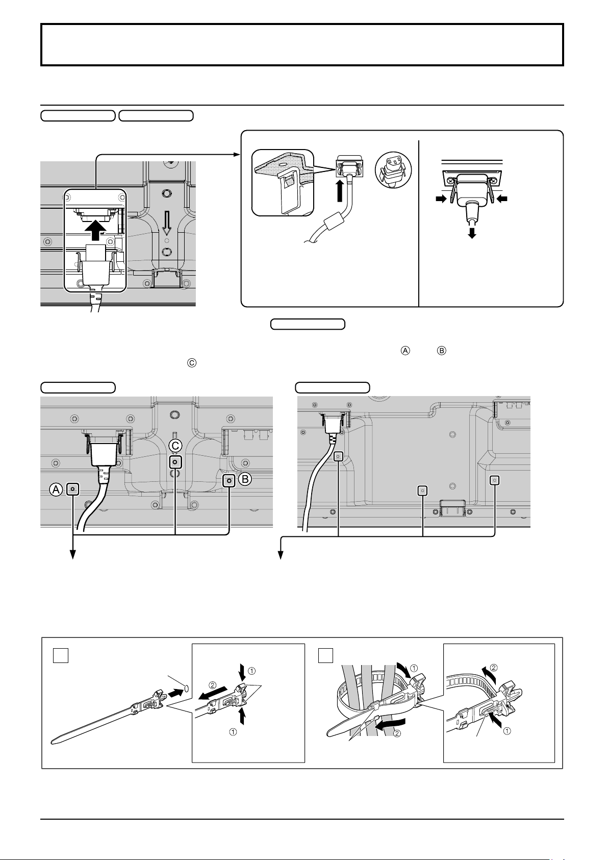
AC cord connection and fixing, cable fixing
50-inch model 65-inch model
Unplug the AC cordAC cord fixing
Unplug the AC cord pressing the
Plug the AC cord into the display unit.
Plug the AC cord until it clicks.
Note:
Make sure that the connector is locked
on both the left and right sides.
two knobs.
Note:
When disconnecting the AC cord, be
absolutely sure to disconnect the AC
cord plug at the socket outlet first.
When using the Wall-hanging bracket (vertical)
Note:
When using the Wall-hanging bracket (vertical) (TY-WK42PV20), use the holes and to secure the cables. If
the clamper is used on the hole , the cables may be caught by the wall-hanging bracket.
50-inch model 65-inch model
Using the clamper
Secure any excess cables with clamper as required.
Note:
One clamper is supplied with this unit. In case of securing cables at three positions, please purchase it separately.
If you need more clampers, purchase them from your dealer. (Available from the customer service)
50-inch model
Attach the clamper
1
Insert the clamper
in a hole.
hole
To remove from the unit:
snaps
Keep pushing
both side snaps
Bundle the cables
2
hooks
Set the
tip in the
hooks
To loosen:
knob
Keep
pushing
the knob
15
Page 18
Connections
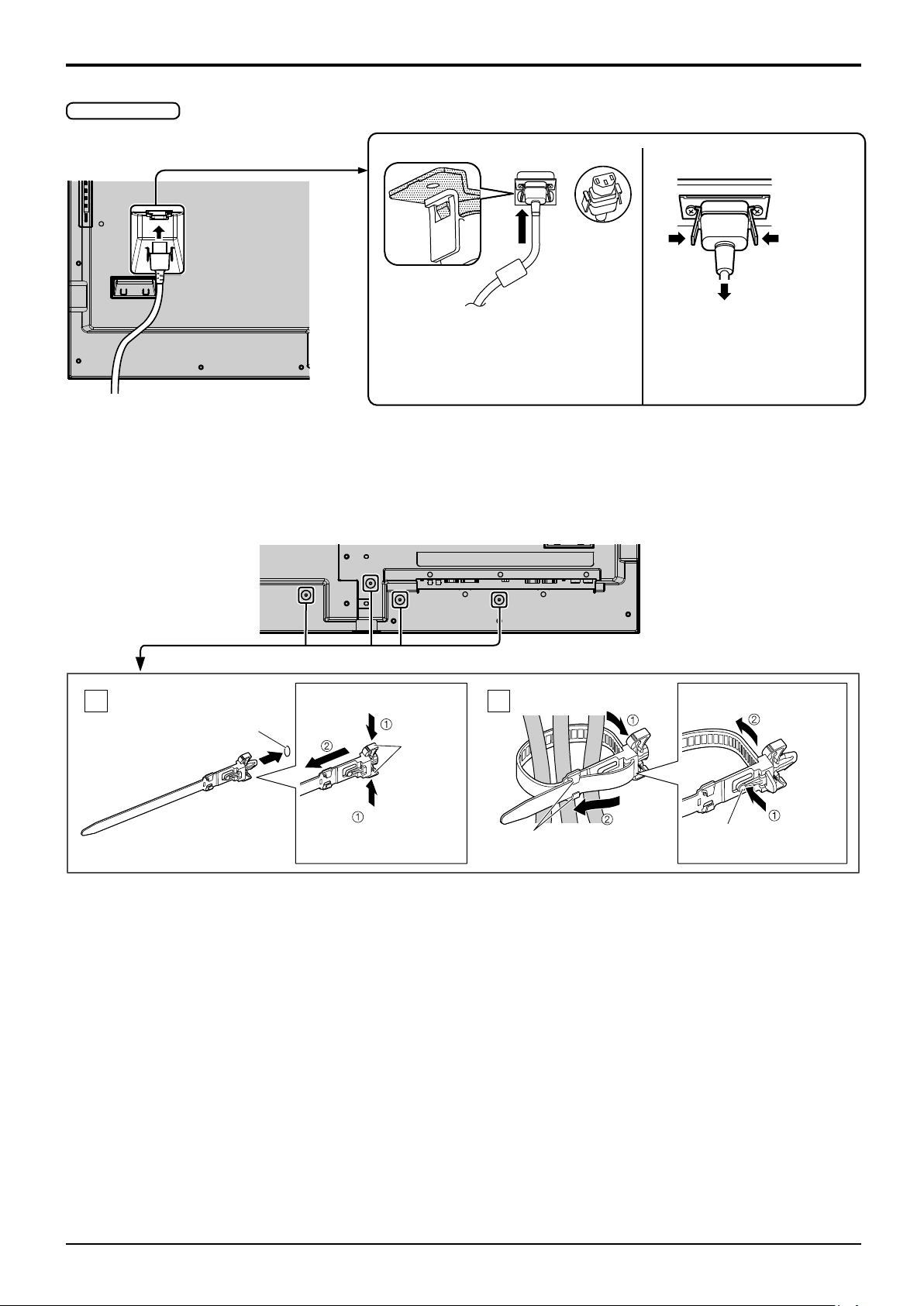
80-inch model
Unplug the AC cordAC cord fixing
Unplug the AC cord pressing the
Plug the AC cord into the display unit.
Plug the AC cord until it clicks.
Note:
Make sure that the connector is locked
on both the left and right sides.
Using the clamper
Secure any excess cables with clamper as required.
Note:
One clamper is supplied with this unit. In case of securing cables at four positions, please purchase it separately.
If you need more clampers, purchase them from your dealer. (Available from the customer service)
two knobs.
Note:
When disconnecting the AC cord, be
absolutely sure to disconnect the AC
cord plug at the socket outlet first.
Attach the clamper
1
Insert the clamper
in a hole.
hole
To remove from the unit:
snaps
Keep pushing
both side snaps
Bundle the cables
2
hooks
Set the
tip in the
hooks
To loosen:
knob
Keep
pushing
the knob
16
Page 19
Video equipment connection
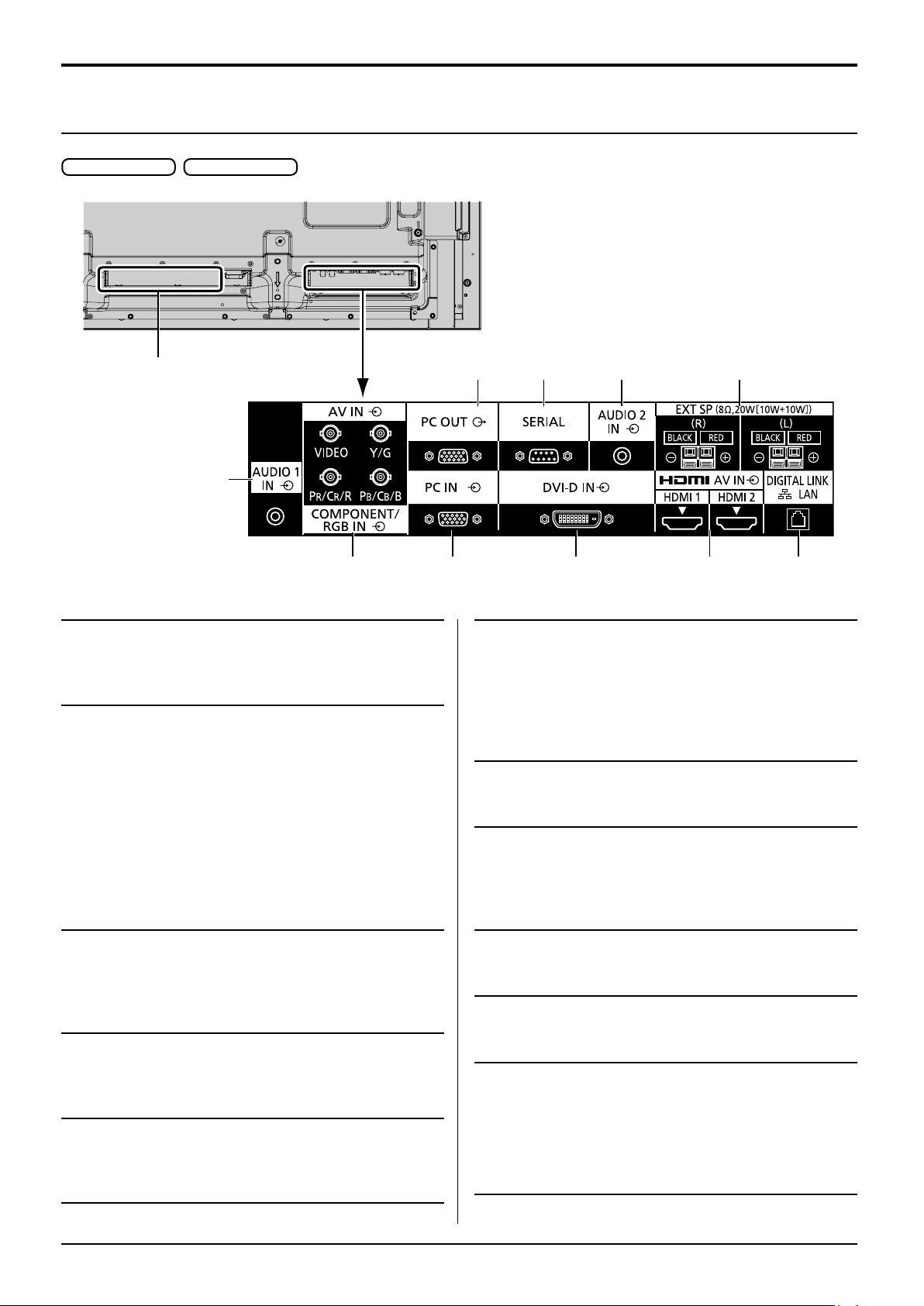
50-inch model 65-inch model
Connections
11
1
1 AUDIO 1 IN : Audio Input Terminal shared
with COMPONENT/RGB IN and
VIDEO IN
(see page 20)
COMPONENT/
2
RGB/VIDEO IN :
COMPONENT / RGB Video
Input Terminal (PR/CR/R, PB/
CB/B, Y/G)
Connect to video equipment
with “YPBPR / YCBCR” or “RGB”
output. (see page 20)
8 7 9 10
32 4 5 6
6 DIGITAL LINK /
LAN :
7 SERIAL : SERIAL Input Terminal
DIGITAL LINK Input Terminal
Control the Display by
connecting to Network.
Alternatively, connect to a
device that sends video and
audio signals via the DIGITAL
LINK terminal. (See page 25)
Control the Display by
connecting to PC. (see page 23)
AV IN : Composite Video Input
Terminal (VIDEO)
Connect to video equipment
with Composite signal output.
(see page 20)
3 PC IN : PC Input Terminal
Connect to video terminal of PC,
video equipment with “YPBPR /
YCBCR” or “RGB” output.
(see page 22)
4 DVI-D IN : DVI-D Input Terminal
Connect to video equipment
with DVI-D output.
(see page 21)
AV IN
5
(HDMI 1, HDMI 2) :
HDMI Input Terminal
Connect to video equipment
such as VCR or DVD player,
etc. (see page 20)
8 PC OUT : Monitor Out Terminal
Video signals being reproduced
on the display are output to
another sub monitor as PC
video signals. (see page 24)
9 AUDIO 2 IN : Audio input terminal shared
with DVI-D IN and PC IN
(see page 21, 22)
10 EXT SP : Speaker Terminal
Connect to external speaker.
(see page 26)
11 SLOT : Expansion slot
(see page 5)
Note: The right side slot is for terminal board with
2-slot width. The terminal board with 1-slot
width does not function when installed in the
right side slot.
17
Page 20
Connections
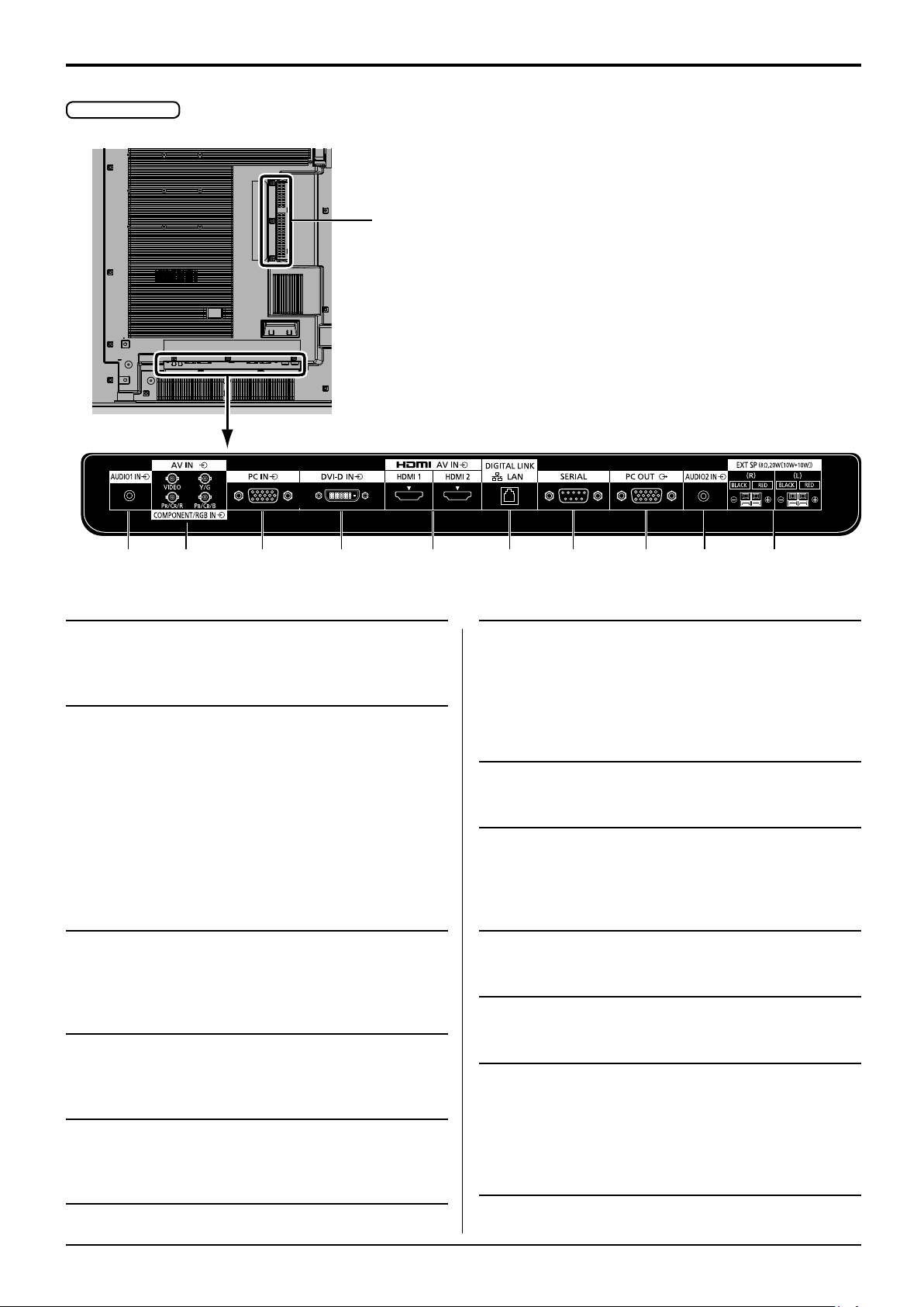
80-inch model
11
321 4 5 6 7 8 9 10
1 AUDIO 1 IN : Audio Input Terminal shared
with COMPONENT/RGB IN and
VIDEO IN
(see page 20)
COMPONENT/
2
RGB/VIDEO IN :
AV IN : Composite Video Input
3 PC IN : PC Input Terminal
4 DVI-D IN : DVI-D Input Terminal
AV IN
5
(HDMI 1, HDMI 2) :
COMPONENT / RGB Video
Input Terminal (PR/CR/R, PB/
CB/B, Y/G)
Connect to video equipment
with “YPBPR / YCBCR” or “RGB”
output. (see page 20)
Terminal (VIDEO)
Connect to video equipment
with Composite signal output.
(see page 20)
Connect to video terminal of PC,
video equipment with “YPBPR /
YCBCR” or “RGB” output.
(see page 22)
Connect to video equipment
with DVI-D output.
(see page 21)
HDMI Input Terminal
Connect to video equipment
such as VCR or DVD player,
etc. (see page 20)
6 DIGITAL LINK /
LAN :
7 SERIAL : SERIAL Input Terminal
8 PC OUT : Monitor Out Terminal
9 AUDIO 2 IN : Audio input terminal shared
10 EXT SP : Speaker Terminal
11 SLOT : Expansion slot
Note: The upper side slot is for terminal board
with 2-slot width. The terminal board with
1-slot width does not function when installed
in the upper side slot.
DIGITAL LINK Input Terminal
Control the Display by
connecting to Network.
Alternatively, connect to a
device that sends video and
audio signals via the DIGITAL
LINK terminal. (See page 25)
Control the Display by
connecting to PC. (see page 23)
Video signals being reproduced
on the display are output to
another sub monitor as PC
video signals. (see page 24)
with DVI-D IN and PC IN
(see page 21, 22)
Connect to external speaker.
(see page 26)
(see page 5)
18
Page 21

Connections
Before connecting
●Before connecting cables, carefully read the operating instructions for the external device to be connected.
●Turn off the power of all devices before connecting cables.
●Take note of the following points before connecting the cables. Failure to do so may result in malfunctions.
When connecting a cable to the unit or a device connected to the unit itself, touch any nearby metallic objects
•
to eliminate static electricity from your body before performing work.
Do not use unnecessarily long cables to connect a device to the unit or to the unit body. The longer the cable,
•
the more susceptible to noise it becomes. Since using a cable while it is wound makes it act like an antenna, it
is more susceptible to noise.
When connecting cables, connect GND first, then insert the connecting terminal of the connecting device in a
•
straight manner.
●Acquire any connection cable necessary to connect the external device to the system that is neither supplied with
the device nor available as an option.
●If the outer shape of the plug of a connection cable is large, it may come in contact with the periphery such as a
back cover or the plug of an adjacent connection cable. Use a connection cable with the suitable plug size for the
terminal alignment.
●If video signals from video equipment contain too much jitter, the images on the screen may wobble. In this case,
a time base corrector (TBC) must be connected.
●When the sync signals output from PC or video equipment are disturbed, for example, when changing settings of
video output, the colour of the video may be disturbed temporarily.
●The unit accepts Composite video signals, YCBCR/YPBPR signals, analogue RGB signals and digital signals.
●Some PC models are not compatible with the unit.
●Use cable compensator when you connect devices to the unit using long cables. Otherwise the image may not
display properly.
●Refer to “Preset Signals” (see page 102) for the types of video signals that can be displayed with the unit.
19
Page 22
Connections
19
3
1
4
2
18
1
11
2
12
3
13
4
14
5
6
15
7
16
8
17
9
18
10
19
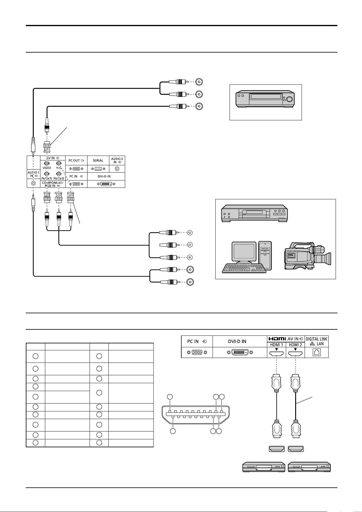
VIDEO and COMPONENT / RGB IN connection
Note:
Additional equipment, cables and adapter plugs shown are not supplied with this set.
L
AUDIO
R
Stereo mini plug (M3)
Pin-BNC
Adapter plug
AUDIO 1 IN:
Shared with VIDEO and
COMPONENT/RGB IN
Notes:
Change the “Component/RGB-in select” setting in the “Setup”
•
menu to “Component” (when Component signal connection)
or “RGB” (when RGB signal connection). (see page 84)
Signals input to COMPONENT/RGB IN terminals correspond
•
to Sync on G or Sync on Y.
OUT
VIDEO
OUT
VCR
Pin-BNC
Adapter plug
HDMI connection
[Pin assignments and signal names]
Pin No.
Signal name
T.M.D.S Data2+
T.M.D.S Data2
Shield
T.M.D.S Data2T.M.D.S Data1+
T.M.D.S Data1
Shield
T.M.D.S Data1T.M.D.S Data0+
T.M.D.S Data0
Shield
T.M.D.S Data0T.M.D.S Clock+
Pin No.
T.M.D.S Clock
Shield
T.M.D.S Clock-
CEC
Reserved
(N.C. on device)
SCL
SDA
DDC/CEC
Ground
+5V Power
Hot Plug Detect
Signal name
PB
PR
Y
L
R
OUT
AUDIO
OUT
DVD Player
, Y , P B , P R
Computer
RGB Camcorder
HDMI
cable
HDMI
AV OUT
HDMI
AV OUT
DVD player
Note:
Additional equipment and HDMI cable shown are not supplied with this set.
20
Page 23
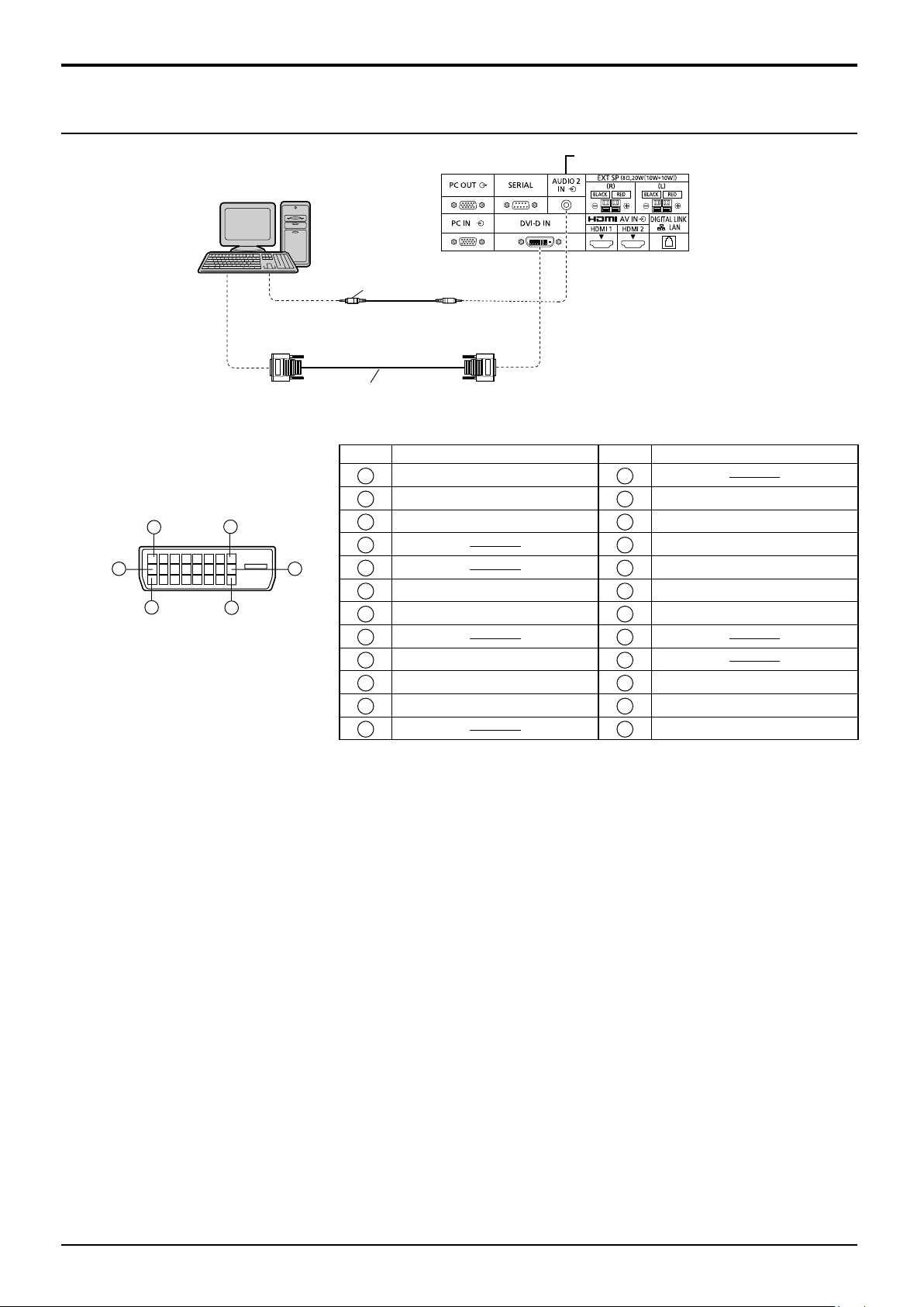
DVI-D IN connection
16
17
24
8
1
9
PC with DVI-D
video out
Stereo mini plug (M3)
DVI-video cable (Within 5 m)
Connections
Shared with PC IN.
DVI-D Input Connector
Pin Layouts
Connection port view
Notes:
Additional equipment and cables shown are not supplied with this set.
•
Use the DVI-D cable complying with the DVI standard. Image deterioration may occur depending on the length or
•
the quality of the cable.
Pin No.
T.M.D.S. data 2-
1
T.M.D.S. data 2+
2
T.M.D.S. data 2 shield
3
4
5
DDC clock
6
DDC data
7
8
T.M.D.S. data 1-
9
T.M.D.S. data 1+
10
T.M.D.S. data 1 shield
11
12 24
Signal Name
Pin No.
13
14
15
16
17
18
19
20
21
22
23
Signal Name
+5 V DC
Ground
Hot plug detect
T.M.D.S. data 0-
T.M.D.S. data 0+
T.M.D.S. data 0 shield
T.M.D.S. clock shield
T.M.D.S. clock+
T.M.D.S. clock-
21
Page 24
Connections
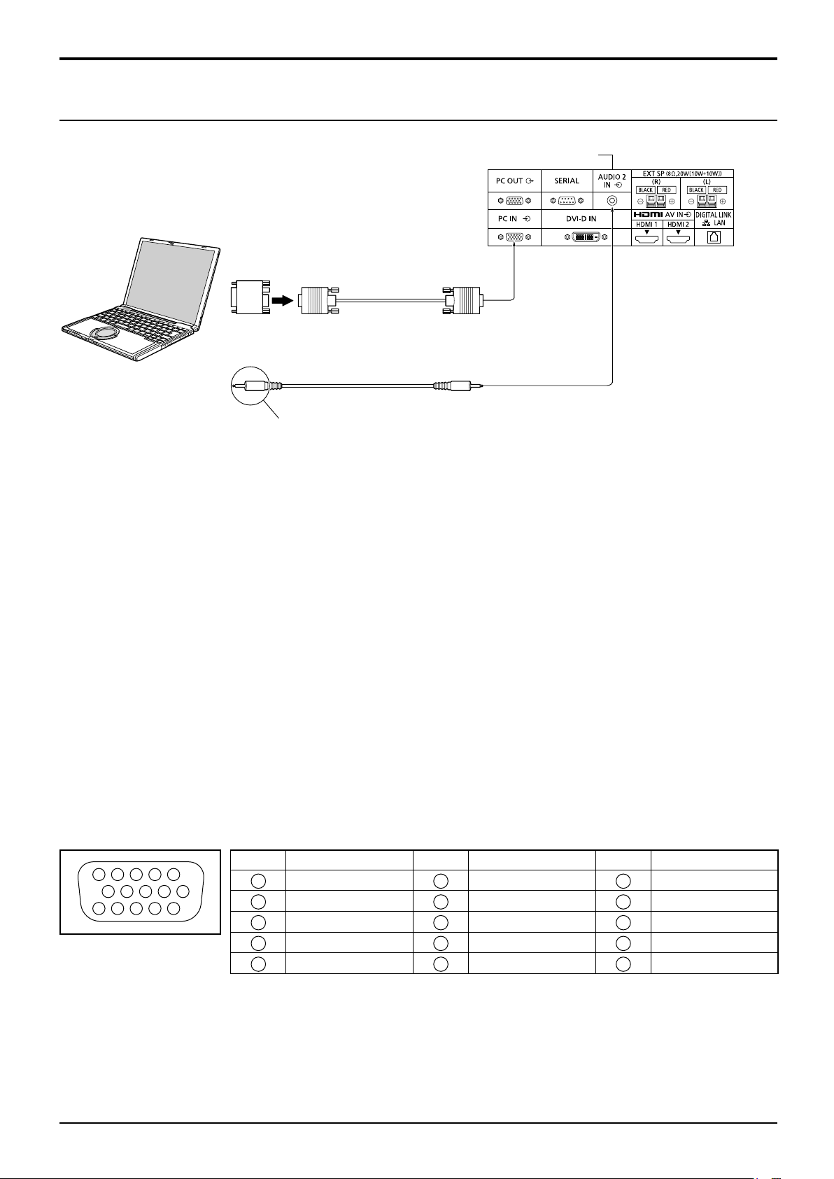
PC Input Terminals connection
Shared with DVI-D IN.
COMPUTER
Conversion adapter
(if necessary)
RGB
PC cable
Audio
Connect a cable which matches
the audio output terminal on the computer.
Notes:
With regard to the typical PC input signals that are described in the applicable input signals list (see page 102),
•
adjustment values such as for the standard picture positions and sizes have already been stored in this unit.
Computer signals which can be input are those with a horizontal scanning frequency of 15 to 110 kHz and vertical
•
scanning frequency of 48 to 120 Hz. (However, the image will not be displayed properly if the signals exceed 1,200 lines.)
The display resolution is a maximum of 1,440 × 1,080 dots when the aspect mode is set to “4:3”, and
•
1,920 × 1,080 dots when the aspect mode is set to “16:9”. If the display resolution exceeds these maximums, it
may not be possible to show fine detail with sufficient clarity.
Additional computer, cables and conversion adapter shown are not supplied with this set.
•
The PC input terminals are DDC2B-compatible. If the computer being connected is not DDC2B-compatible, you
•
will need to make setting changes to the computer at the time of connection.
Some PC models cannot be connected to the set.
•
There is no need to use an adapter for computers with DOS/V compatible Mini D-sub 15P terminal.
•
The computer shown in the illustration is for example purposes only.
•
Additional equipment and cables shown are not supplied with this set.
•
Do not set the horizontal and vertical scanning frequencies for PC signals which are above or below the specified
•
frequency range.
Component Input is possible with the pin 1, 2, 3 of the Mini D-sub 15P Connector.
•
Change the “Component/RGB-in select” setting in the “Setup” menu to “Component”
•
(when Component signal connection) or “RGB” (when RGB signal connection). (see page 84)
(Female)
Mini D-sub 15p
(Male)
Stereo mini plug (M3)
Signal Names for Mini D-sub 15P Connector
4 5
10
15 14 13 12 11
Pin Layout for PC Input
Terminal
1
2
6 7 8 3 9
Pin No. Signal Name Pin No. Signal Name Pin No. Signal Name
1
2
3
4
5
R (P
G (Y)
B (P
NC (not connected)
GND (Ground)
22
R/CR
B/CB
)
)
6
7
8
9
10
GND (Ground)
GND (Ground)
GND (Ground)
+5 V DC
GND (Ground)
NC (not connected)
11
12
13
14
15
HD/SYNC
SDA
VD
SCL
Page 25
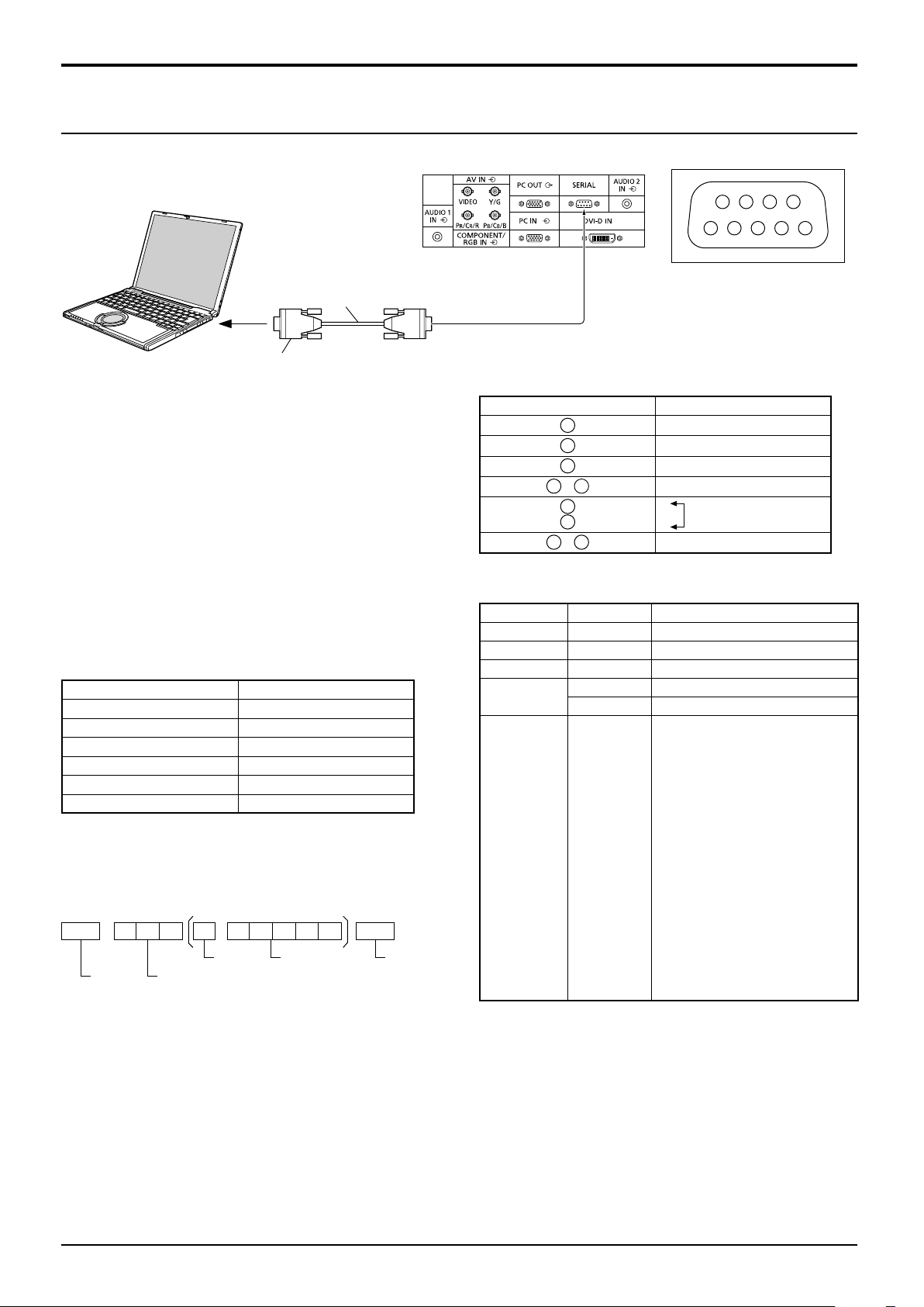
SERIAL Terminals connection
52
Connections
The SERIAL terminal is used when the Display is controlled by a computer.
(Male)
COMPUTER
6789
Pin layout for SERIAL Terminal
RS-232C Straight cable
(Female)
D-sub 9p
Notes:
Use the RS-232C straight cable to connect the
•
computer to the Display.
The computer shown is for example purposes only.
•
Additional equipment and cables shown are not
•
supplied with this set.
The SERIAL terminal conforms to the RS-232C interface
specification, so that the Display can be controlled by a
computer which is connected to this terminal.
The computer will require software which allows the
sending and receiving of control data which satisfies the
conditions given below. Use a computer application such
as programming language software. Refer to the
documentation for the computer application for details.
Communication parameters
Signal level RS-232C compliant
Synchronization method Asynchronous
Baud rate 9600 bps
Parity None
Character length 8 bits
Stop bit 1 bit
Flow control None
Basic format for control data
The transmission of control data from the computer starts with
a STX signal, followed by the command, the parameters, and
lastly an ETX signal in that order. If there are no parameters,
then the parameter signal does not need to be sent.
STX C1 C2 C3 P1 P2 P3 P4: P5 ETX
Start
(02h)
Colon Parameter(s)
3-character
command (3 bytes)
(1 - 5 bytes)
End
(03h)
Signal names for D-sub 9P connector
Pin No. Details
2
3
5
4
6
•
7
8
1
9
•
R X D
T X D
GND
Non use
(Shorted in this set)
NC
These signal names are those of computer specifications.
Command
Command Parameter Control details
PON None Power ON
POF None Power OFF
AVL ** Volume 00 - 63
AMT
IMS None
0 Audio MUTE OFF
1 Audio MUTE ON
Input select (toggle)
SL1
S1A
S1B
VD1
YP1
HM1
HM2
DV1
PC1
DL1
MG1
NW1
MV1
WB1
SLOT input (SLOT INPUT)
SLOT input (SLOT INPUT A)
SLOT input (SLOT INPUT B)
VIDEO input (VIDEO)
COMPONENT/RGB IN input
(COMPONENT/RGB)
HDMI 1 input (HDMI1)
HDMI 2 input (HDMI2)
DVI-D IN input (DVI-D)
PC IN input (PC)
DIGITAL LINK input (DIGITAL LINK)
MIRRORING input (MIRRORING)
Panasonic APPLICATION input
(Panasonic APPLICATION)
Memory viewer input
(MEMORY VIEWER)
WhiteBoard input (WHITEBOARD)
With the power off, this display responds to PON
Notes:
If multiple commands are transmitted, be sure to wait for the response for the first command to come from this
•
command only.
unit before sending the next command.
Additional computer and cables shown are not supplied with this set.
•
If this unit receives a command, the response is normally sent within 200 ms. If there is no response even after
•
one second, a communication error might have occurred. Send the command again.
If an incorrect command is sent by mistake, this unit will send an “ER401” command back to the computer.
•
S1A and S1B of Command IMS are available only when a dual input terminal board is attached.
•
Consult your local Panasonic dealer for detail instructions on command usage.
•
For more details, visit the following web site.
https://panasonic.net/cns/prodisplays/
134
23
Page 26
Connections
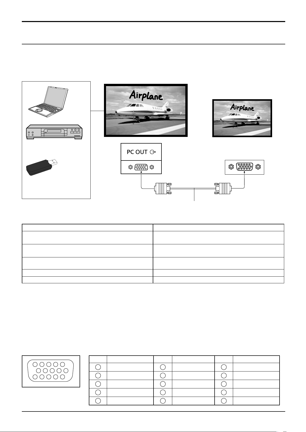
PC OUT connection
The image being reproduced on the display including the image input from video equipment and the contents drawn
on the whiteboard can be displayed on another sub monitor.
To use the function, set “Monitor out” to “On” in “Setup”. (see page 82)
Note: Setting it to “On” will adjust the “Picture” menu values to the standard values.
Sub monitor
Computer, DVD player and
other video equipment
PC input terminal
USB memory
(Female)
(To be viewed in Memory
Viewer)
(Male)
Mini D-sub 15p cable
(Commercially available)
Input signals and drawn images that can be output
Input signal / Drawn image Output signal
HDMI input signal (HDMI 1, HDMI 2)
HDCP (copy protection) not supported
DVI-D input signal (DVI-D IN)
HDCP (copy protection) not supported
PC input signal (PC IN)
When “Component/RGB-in select” is set to “RGB”
1,920 x 1,080@50 Hz or 1,920 x 1,080@60 Hz
1,920 x 1,080@50 Hz or 1,920 x 1,080@60 Hz
1,920 x 1,080@50 Hz or 1,920 x 1,080@60 Hz
Whiteboard screen 1,920 x 1,080@60 Hz
Memory Viewer screen (MEMORY VIEWER) 1,920 x 1,080@60 Hz
Notes:
Connection cables are not supplied with this unit.
•
The aspect ratio of the output signal is changed so that it can be shown on the screen.
•
The following input signals cannot be output.
•
Component input (COMPONENT/RGB IN)
Composite video input (VIDEO)
MIRRORING input
Panasonic APPLICATION input
DIGITAL LINK input
Pin Layout and Signal Names of Monitor Out Terminal (Mini-D-sub 15P)
3
4 5
2
9
10
15 14 13 12 11
1
6 7 8
Pin No. Signal Name Pin No. Signal Name Pin No. Signal Name
1
2
3
4
NC (not connected)
5
GND (Ground)
R
G
B
6
7
8
9
10
GND (Ground)
GND (Ground)
GND (Ground)
+5 V DC
GND (Ground)
24
11
NC (not connected)
12
NC (not connected)
13
14
15
NC (not connected)
HD
VD
Page 27
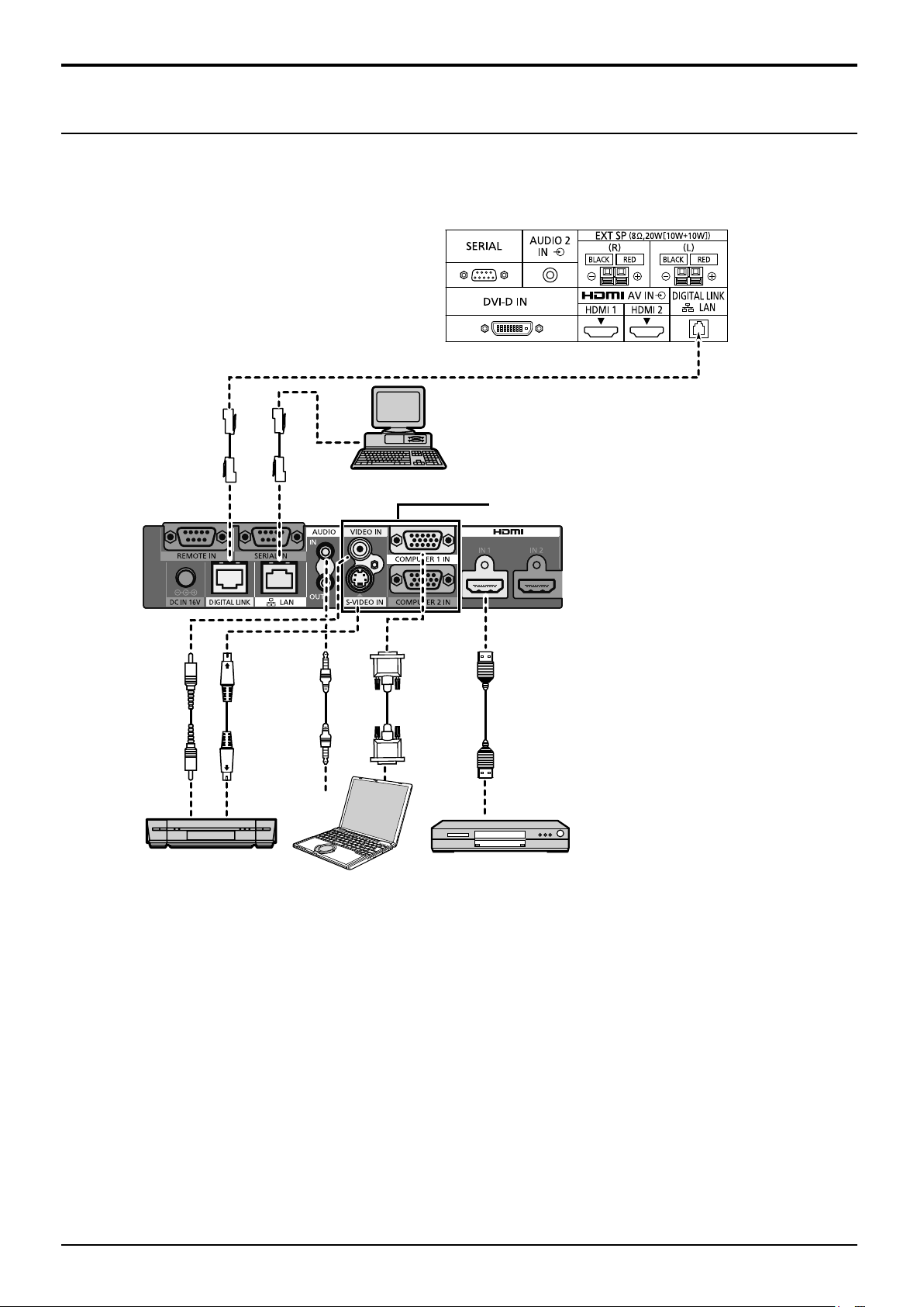
Connections
Example connection using the DIGITAL LINK Terminal
A twisted pair cable transmitter, such as the Panasonic device that supports DIGITAL LINK output (ET-YFB100G,
ET-YFB200G) uses twisted pair cables to transmit inputted video and audio signals, and these digital signals can be
input to the Display via the DIGITAL LINK terminal.
Display Connection Terminals
Control
Computer
When a Panasonic ET-YFB100G is used
Analogue signal is output as Digital signal.
Video Cassette Recorder DVD Player
Computer
Notes:
Video equipment and cables shown are not supplied with this unit.
•
When connecting with DIGITAL LINK, be sure to configure each of the “Network settings” settings.
•
For the cautions for DIGITAL LINK setting and connection, refer to “Operating Instructions - Network Operations”.
Corresponding signal for DIGITAL LINK input is the same as that of HDMI input. (see page 102)
•
25
Page 28
Connections
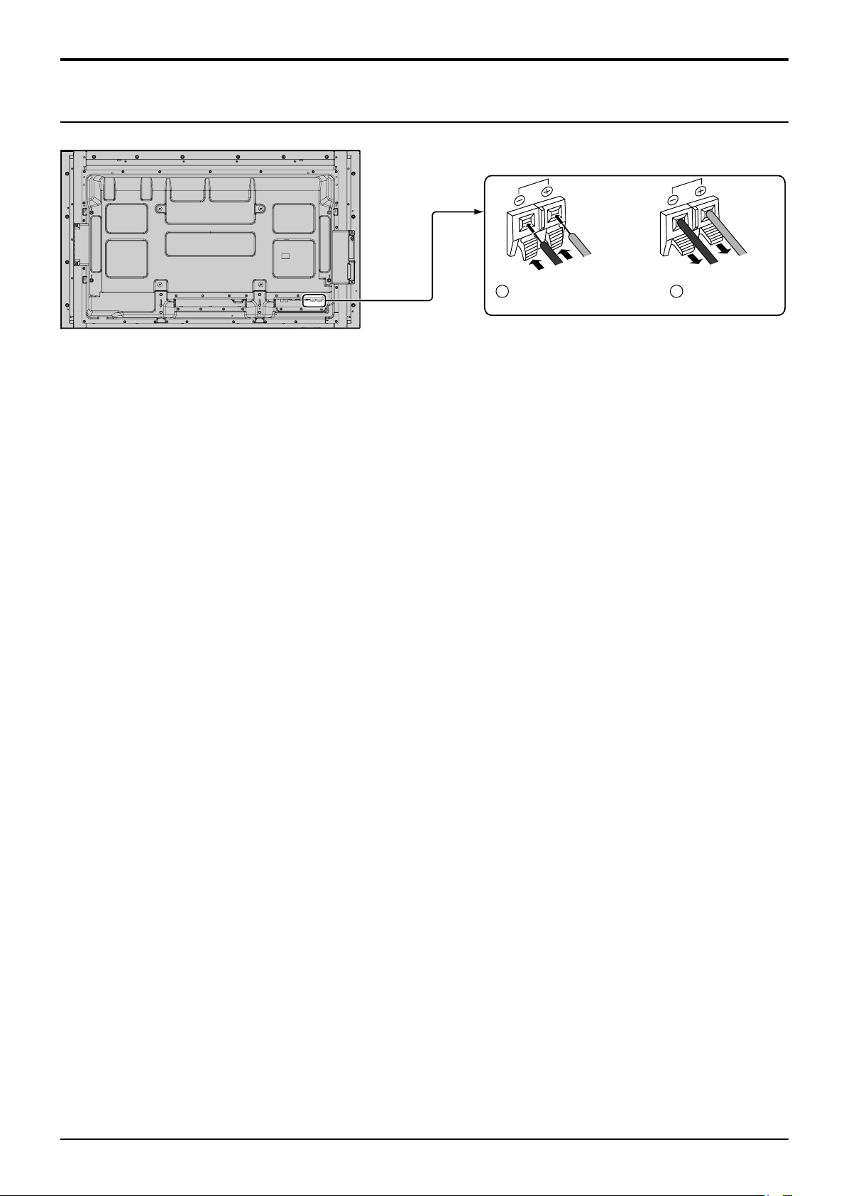
1
2
Speaker connection
Please use 8 Ω/10 W speaker.
Red
Black
While pressing the lever,
insert the core wire.
Red
Black
Return the lever.
26
Page 29
Power On / Off
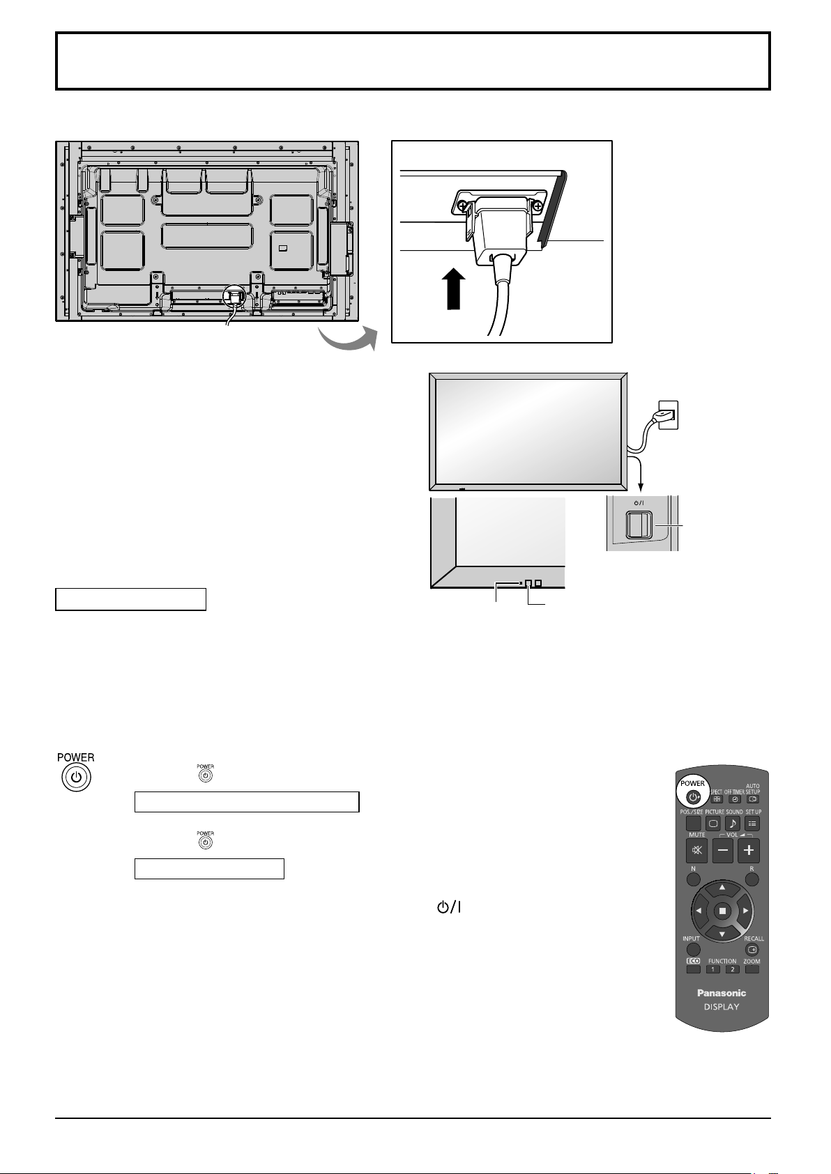
Connecting the AC cord plug to the Display.
Connecting the plug to the Wall Outlet
Notes:
Main plug types vary between countries. The
•
power plug shown at right may, therefore, not be
the type fitted to your set.
When disconnecting the AC cord, be absolutely
•
sure to disconnect the AC cord plug at the socket
outlet first.
Press the Power switch on the Display to turn the
set on: Power-On.
Power switch
Power Indicator: Blue
[Starting up the touch screen and network]
It takes some time for the touch screen and network
to start up just after the power is turned on.
During that time, “Touch screen settings”, “Network
settings” in the “Setup” menu is grayed out and
cannot be set.
Press the button on the remote control to turn the Display off.
Power Indicator: Orange or purple
Press the button on the remote control to turn the Display on.
Power Indicator: Blue
Turn the power to the Display off by pressing the switch on the unit,
when the Display is on or in standby mode.
Notes:
Operate pointing the remote control directly at the unit’s Remote Control
•
Sensor.
During operation of the power management function, the power indicator
•
turns purple in the power off state.
Power Indicator
Remote Control Sensor
27
Page 30
Power On / Off
1
2
1
2
1
2
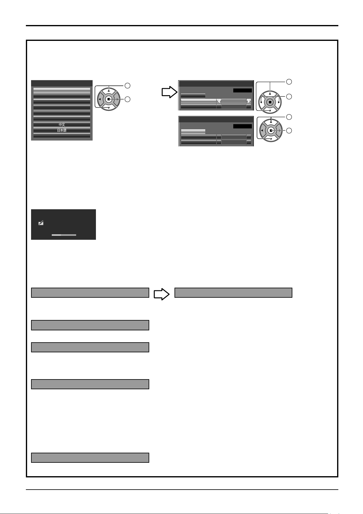
When first switching on the unit
Following screen will be displayed when the unit is turned on for the first time.
Use the remote control to make the settings. Pressing the buttons on the main unit or multi-touch operation will not work.
OSD language
OSD language
English (UK)
Deutsch
Français
Italiano
Español
ENGLISH (US)
Русский
Select the
language.
Set.
Day/Time settings
Day/Time settings
Time MON 99:99
Set
Day
Day/Time settings
Time TUE 99:99
Set
Day
MON
99:99Time
TUE
18:00Time
Select “Day”
or “Time”.
Setup “Day”
or “Time”.
Select “Set”.
Set.
Notes:
Once the items are set, the screens won’t be displayed when switching on the unit next time.
•
After the setting, the items can be changed in the following menus.
•
OSD language (see page 83)
Day/Time settings (see page 72)
Power ON message
The following message may be displayed when turning the unit power ON:
WhiteBoard Startup screen
WhiteBoard
Now Loading...
When the power is turned ON with the Input switch of the WHITEBOARD, the built-in WhiteBoard starts up.
Also, the following startup screens are displayed depending on the input.
MIRRORING
MEMORY VIEWER
Touch screen connection status display
When not connected to a computer via USB
Initializing Touch Screen... Touch Screen detected.
Touch operation of the display is possible after this
message appears.
When connected to a computer via USB
Touch Screen connected to external device.
No activity power off Precautions
’No activity power off’ is enabled.
If “No activity power off” in Setup menu is set to “Enable”, a warning message is displayed every time the power
is turned ON. (see page 83)
Power Management Information
Last turn off due to ‘Power management’.
If “Power management” is functioned, an information message is displayed every time the power is turned ON.
(see page 78)
These message displays can be set with the following menu: Options menu
Power on message (No activity power off)
(see page 91)
Power on message (Power management)
(see page 91)
COLOR UNIVERSAL DESIGN Information
’COLOR UNIVERSAL DESIGN’ is enabled.
The information is displayed when “Setup” - “COLOR UNIVERSAL DESIGN” is set to “On”. (see page 84)
28
Page 31

Selecting the input signal
Press to select the input signal to be played back from the equipment which has been
connected to the Display.
Alternatively you can press , press to select the input and press .
HDMI input in HDMI 1 terminal
HDMI input in HDMI 2 terminal
1
Input signal in a Terminal Board
Composite video input in VIDEO terminal
Component/RGB input in COMPONENT/RGB IN terminal
Computer’s signal input in PC IN terminal
DVI-D input in DVI-D IN terminal
DIGITAL LINK input in DIGITAL LINK terminal
Select this input when using the “MIRRORING” function. (see page 59)
Select this input when using “Wireless Manager” via wired/wireless LAN. (see page 58)
Select this input when using the Memory Viewer function. (see page 42)
The screen switches WHITEBORAD input
*
3
*
. (see page 49)
2
*
*
1
“SLOT INPUT” appears when an optional Terminal Board is connected.
When a Terminal Board with dual input terminals is connected, “SLOT INPUT A” and “SLOT INPUT B” will appear.
When a Terminal Board incompatible with the Display is installed, “Non-Compatible Function Board” is displayed.
*
2 “COMPONENT” may be displayed as “RGB” depending on the setting of “Component/RGB-in select”.
(see page 84)
*
3 The WHITEBOARD input can be selected when “Touch screen” of “Touch screen settings” is “On”. (see page 73)
Notes:
Selecting is also possible by pressing the INPUT button
•
on the unit.
Outputs the sound as set in “Audio input select” in the
•
Options menu. (see page 93)
Select to match the signals from the source connected
•
to the component/RGB input terminals. (see page 84)
Image retention (image lag) may occur on the LCD
•
display panel when a still picture is kept on the panel
ENTER/
+
VOL
-
MENU
INPUT
for an extended period. To prevent such a problem,
using the screensaver is recommended. (see page 76)
The connection of the Wireless Manager is interrupted
•
if the input is switched from Panasonic APPLICATION
to MIRRORING or MEMORY VIEWER.
The connection is also interrupted when the input is
switched from MIRRORING to something else during
MIRRORING connection with MIRRORING input.
Please check the setting again after switching the input.
/
/
29
Page 32

Basic Controls
50-inch model 65-inch model
Main Unit
Touch panel IR transmission part
Installed on the four sides of the liquid crystal panel.
Remote control
sensor
Power Indicator
The Power Indicator will light.
Power-OFF ...
•
Indicator not illuminated (The unit will still
consume some power as long as the power
cord is still inserted into the wall outlet.)
Standby .... Orange
•
Purple (When “Slot power” is set to “On” and
Terminal Board is installed.)
Purple (Depending on the type of the function
board installed, when the power is supplied to
the slot. See page 90)
Purple (When “Network control” is set to “On” or
“Wireless network standby” is set to “On”. Refer
to “Operating Instructions, Network Operations”)
Purple (When “Quick launch” is set to “On”. See page 74)
Power-ON
•
HDMI1 power management
•
... Blue
HDMI2 power management
.................
*
These functions are not supported by TH-80BF1E, TH-65BF1E, TH-50BF1E.
PC power management (DPMS)
•
Purple (With HDMI1 or HDMI2 input signal. See page 78)
................. Purple (With PC input signal. See page 78)
DVI-D power management
•
................. Purple (With DVI input signal. See page 78)
Notes:
If the power indicator is purple, power consumption during standby
•
is generally larger than that of when the power indicator is orange.
Considering COLOR UNIVERSAL DESIGN, purple lights up
•
brighter than blue.
About COLOR UNIVERSAL DESIGN (CUD) (see page 84)
Brightness Sensor
Detects the brightness in the viewing environment. (see page 78)
ENTER/
/
+
VOL
-
/
MENU
INPUT
USB (VIEWER): Connect to USB memory. (see page 43)
USB (TOUCH): When using the “WhiteBoard Software”
from the supplied CD-ROM, connect the
computer via USB cable. (see page 57)
SLOT: Terminal board (optional accessories) insert slot
(see page 5)
Note:
The right side slot is for terminal board with 2-slot width.
The terminal board with 1-slot width does not function
when installed in the right side slot.
Enter / Aspect button
(see page 33, 60)
Volume Adjustment
Volume Up “+” Down “–”
When the menu screen is displayed:
“+” : press to move the cursor up
“–” :
press to move the cursor down
(see page 60)
MENU Screen ON / OFF
Each time the MENU button is pressed, the menu screen will switch.
(see page 60)
30
INPUT button (INPUT signal selection)
(see page 29)
Main Power On / Off Switch
Page 33

Basic Controls
80-inch model
Main Unit
Touch panel IR transmission part
Installed on the four sides of the liquid crystal panel.
Remote control
sensor
Power Indicator
The Power Indicator will light.
Power-OFF
•
... Indicator not illuminated (The unit will still
consume some power as long as the power
cord is still inserted into the wall outlet.)
Standby .... Orange
•
Purple (When “Slot power” is set to “On” and
Terminal Board is installed.)
Purple (Depending on the type of the function
board installed, when the power is supplied to
the slot. See page 90)
Purple (When “Network control” is set to “On” or
“Wireless network standby” is set to “On”. Refer
to “Operating Instructions, Network Operations”)
Purple (When “Quick launch” is set to “On”. See page 74)
Power-ON
•
HDMI1 power management
•
... Blue
HDMI2 power management
.................
*
These functions are not supported by TH-80BF1E, TH-65BF1E, TH-50BF1E.
PC power management (DPMS)
•
Purple (With HDMI1 or HDMI2 input signal. See page 78)
................. Purple (With PC input signal. See page 78)
DVI-D power management
•
................. Purple (With DVI input signal. See page 78)
Notes:
If the power indicator is purple, power consumption during standby
•
is generally larger than that of when the power indicator is orange.
Considering COLOR UNIVERSAL DESIGN, purple lights up
•
brighter than blue.
About COLOR UNIVERSAL DESIGN (CUD) (see page 84)
ENTER/
/
+
VOL
-
/
Brightness Sensor
Detects the brightness in the viewing environment. (see page 78)
USB (VIEWER): Connect to USB memory. (see page 43)
USB (TOUCH): When using the “WhiteBoard
Software” from the supplied CD-ROM,
connect the computer via USB cable.
(see page 57)
SLOT: Terminal board (optional accessories) insert
slot (see page 5)
Note:
The upper side slot is for terminal board with 2-slot
width. The terminal board with 1-slot width does not
function when installed in the upper side slot.
Enter / Aspect button
(see page 33, 60)
Volume Adjustment
Volume Up “+” Down “–”
When the menu screen is displayed:
“+” : press to move the cursor up
“–” : press to move the cursor down
(see page 60)
MENU
INPUT
MENU Screen ON / OFF
Each time the MENU button is pressed, the menu screen will switch.
(see page 60)
INPUT button (INPUT signal selection)
(see page 29)
Main Power On / Off Switch
31
Page 34

Basic Controls
30 min 60 min
0 min (Cancel)
90 min
1
2
3
4
Remote Control Transmitter
ACTION button
Press to make selections.
ASPECT button
Press to adjust the aspect.
(see page 33)
Standby (ON / OFF) button
The Display must first be plugged
into the wall outlet and turned on at
the power switch (see page 27).
Press this button to turn the Display
On, from Standby mode. Press
it again to turn the Display Off to
Standby mode.
POS./SIZE button
(see page 62)
OFF TIMER button
The Display can be preset to switch to
stand-by after a fixed period. The setting
changes to 30 minutes, 60 minutes, 90 minutes
and 0 minutes (off timer cancelled) each time
the button is pressed.
When three minutes remain, “Off timer 3 min”
will flash.
The off timer is cancelled if a power interruption
occurs.
AUTO SETUP button
Automatically adjusts the position/
size of the screen. (see page 62)
SET UP button (see page71)
PICTURE button
(see page 65)
Sound mute On / Off
Press this button to mute the
sound.
Press again to reactivate sound.
Sound is also reactivated when
power is turned off or volume level
is changed.
N button
(see page 64, 65, 66, 70)
POSITION buttons
INPUT button
Press to select Input signal
sequentially. (see page 29)
ECO MODE (ECO)
Press to change the ECO MODE
setup status. (see page 78)
FUNCTION buttons (FUNCTION)
(see page 81)
SOUND button (see page 70)
Volume Adjustment
Press the Volume Up “+” or Down
“–” button to increase or decrease
the sound volume level.
R button (see page 60)
Press the R button to return to
previous menu screen.
RECALL button
Press the “RECALL” button to
display the current system status.
Input label
Aspect mode (see page 33)
Audio input (see page 93)
Profile name (see page 69)
Off timer
The off timer indicator is
displayed only when the off
timer has been set.
Clock display (see page 90)
PC
♪ COMPONENT
4:3
Memory name: MEMORY2
1
2
32
10:00
4
Off timer
90min
Digital Zoom (see page 34)
3
Page 35

ASPECT Controls
The Display will allow you to enjoy viewing the picture at its maximum size, including wide screen cinema format
picture.
Note:
Be aware that if you put the display in a public place for commercial purposes or a public showing
and then use the aspect mode select function to shrink or expand the picture, you may be violating
the copyright under copyright law. It is prohibited to show or alter the copyrighted materials of other
people for commercial purposes without the prior permission of the copyright holder.
Press repeatedly to move through the aspect options:
For details about the aspect mode, please see “List of Aspect Modes” (page 100).
[from the unit]
ENTER/
TH-80BF1U, TH-65BF1U, TH-50BF1U:
For VIDEO (S VIDEO) signal input:
4:3 ZOOM JUSTFULL
For PC signal input: For SD signal input (525 (480) / 60i • 60p, 625 (575) / 50i • 50p):
4:3 ZOOM FULL 4:3 ZOOM JUSTFULL
For HD signal input [1125 (1080) / 60i • 50i • 60p • 50p • 24p • 25p • 30p • 24psF, 1250 (1080) / 50i, 750 (720) / 60p • 50p]:
4:3 H-FILL ZOOM
With the following inputs, the aspect will be fixed to “FULL” and you cannot switch it.
MIRRORING, MEMORY VIEWER, WHITEBOARD
TH-80BF1E, TH-65BF1E, TH-50BF1E, TH-80BF1W, TH-65BF1W, TH-50BF1W:
For VIDEO (S VIDEO) signal input:
4:3 Zoom1 16:9Zoom2 Zoom3 14:9 Just
For PC signal input: For SD signal input (525 (480) / 60i • 60p, 625 (575) / 50i • 50p):
4:3 Zoom 16:9
For HD signal input [1125 (1080) / 60i • 50i • 60p • 50p • 24p • 25p • 30p • 24psF, 1250 (1080) / 50i, 750 (720) / 60p • 50p]:
4:3
With the following inputs, the aspect will be fixed to “16:9” and you cannot switch it.
MIRRORING, MEMORY VIEWER, WHITEBOARD
Note:
The aspect mode is memorized separately for each input terminal.
4:3 Full Zoom1
14:9Just
The aspect mode changes each time the ENTER button is pressed.
FULL JUST
4:3 Zoom1 16:9Zoom2 Zoom3 14:9 Just
Zoom2
16:9
Zoom3
All Aspect mode
Set “All Aspect” to “On” in Options menu to enable the extended aspect mode (page 91). When All Aspect mode, the aspect
mode of pictures is switched as follows. For details about the aspect mode, please see “List of Aspect Modes”. (page 100)
For VIDEO (S VIDEO) signal input:
4:3 Zoom1 16:9Zoom2 Zoom3 14:9 Just
For PC signal input:
4:3 Zoom
For HD signal input [1125 (1080) / 60i • 50i • 60p • 50p • 24p • 25p • 30p • 24psF, 1250 (1080) / 50i, 750 (720) / 60p • 50p]:
4:3 Full Zoom1 16:9 Just1Zoom2 Zoom3 14:9 Just2 4:3 (1) 4:3 (2)
16:9
For SD signal input (525 (480) / 60i
4:3 Zoom1 16:9 JustZoom2 Zoom3 14:9
•
60p, 625 (575) / 50i
•
50p):
33
Page 36

Digital Zoom
This displays an enlargement of the designated part of the displayed image.
Display the operation guide.
1
Press to access Digital Zoom.
The operation guide will be displayed.
During Digital Zoom, only the following buttons can be operated.
1
Exit
[Remote control]
Select the area of the image to be enlarged.
2
Select the magnification required for the enlarged display.
3
Press on the enlargement location to select.
Each time this is pressed, the magnification factor changes.
This is shown in the image being displayed.
OFF TIMER button
VOL button
MUTE button
POSITION /
ACTION button
The cursor will move.
[Unit]
ENTER/
/
+
VOL
-
/
VOL button
2
Exit
× 1
Return to normal display (quit Digital Zoom).
4
Press to exit from the Digital Zoom.
Notes:
When power goes OFF (including “Off Timer” operation), Digital Zoom terminates.
•
The Digital Zoom function cannot be selected while in the following operation state:
•
When WHITEBOARD input.
When two screen display.
When Screensaver (except for Negative image) is running (see page 76)
When the thumbnail view or file list view of Memory Viewer is displayed
While Digital Zoom is in operation, “Adjusting Pos./Size” cannot be used.
•
× 2
34
× 3
× 4
Page 37

MULTI PIP
You can display two pictures, such as a video image and computer image, in a two-screen display.
Notes:
If “Input lock” in Options menu is set to other than “Off”, two screen display function isn’t available (see page 89).
•
2k1k signals that are received with the Dual Link HD-SDI Terminal Board (TY-FB11DHD) cannot be displayed in
•
two-screen display.
MULTI PIP settings
Set the functions and mode for two-screen display in “MULTI PIP settings” in the Setup menu. (see page 75)
PIP mode
There are two modes for two screen display:
Pic in Pic
Displays two input images combined.
SLOT INPUT
Pic in WHITEBOARD
Displays the built-in WhiteBoard with the other input image combined.
Main screen input
Sub screen input
The following four system inputs are combined:
A Panasonic APPLICATION
B SLOT INPUT
C HDMI1/HDMI2/DVI-D/DIGITAL LINK/COMPONENT/PC
D VIDEO
Note:
Two screen display cannot be displayed with the same system
inputs such as HDMI1-DVI-D combined.
WHITEBOARD
PC
Note:
The aspect is fixed to 16:9 on the main screen.
The aspect varies on the sub screen depending on the input signal.
Video (S video) signal, SD signal, PC signal: 4:3
HD signal: 16:9
Main screen is fixed to WHITEBOARD.
Inputs supported for the sub screen: HDMI1/HDMI2/DVI-D/DIGITAL LINK/
COMPONENT/PC/VIDEO/SLOT INPUT
Using Two Screen Display
Set “MULTI PIP” in “MULTI PIP settings” to “On” (see page 75).
Two screen display appears.
Using the FUNCTION button
On/Off of “MULTI PIP” switches.
“MULTI PIP settings” menu appears.
Switching Sub Screen Position Changing the Size of Sub Screen
Press to switch the sub screen position. Press to change the size of the sub screen.
Note:
Please use the “Function button settings” to set the
FUNCTION button (see page 81).
Note:
Alternatively, “Sub screen size” and “Sub screen position” in “MULTI PIP settings” can be used for the same
operation (see page 75).
35
Page 38

Multi-touch Operation
The built-in touch panel function of the display enables the screen control with a finger or the supplied pen.
This section explains about the multi-touch operation on the display main unit.
Note:
To enable multi-touch operation, select “Setup” - “Touch screen settings” and set “Touch screen” to “On”.
(see page 73)
Touch gestures
You can use the following touch operations.
Name Operation
Tap (single tap)
Touch once lightly
Double-tap
Touch twice
Scroll
Slide a finger
■ Control menu operation
Controlling the display setting menus.
•
Starting the Touch Zoom mode.
•
Starting the whiteboard.
•
■ Memory Viewer operation
Showing/hiding the touch operation icons when the MEMORY VIEWER
input is selected.
You can tap the displayed icons to perform operation.
Memory Viewer see page 42
■ Touch Zoom operation
Enlarging the image up to about three times its normal size during
Touch Zoom.
When the image is already enlarged, the zoom rate will be returned to
100%.
Touch zoom see page 41
■ Touch Zoom operation
Moving the displayed position of the image while the image is enlarged.
Flick from the screen edge
Slide a finger from the screen edge
36
■ Memory Viewer operation
Skipping forward or backward the file.
Memory Viewer see page 42
■ Control menu display
Displaying the control menu (Flick).
Page 39

Multi-touch Operation
Name Operation
Zoom in
Pinch out with two fingers
Zoom out
Pinch in with two fingers
■ Touch Zoom operation
Enlarging the image.
■ Touch Zoom operation
Shrinking the image.
Operations that can be performed with multi-touch gestures
Selecting the input and adjusting the volume (see page 38)
Touch Zoom (see page 41)
Memory Viewer operation (see page 42)
Pen drawing on the built-in WhiteBoard (see page 49)
Pen drawing in the WhiteBoard Software (see page 57)
Controlling the display setting menus (see page 61)
Notes for multi-touch operation
Always use a finger or the supplied pen to perform multi-touch operation or pen drawing. Do not use a hard or
sharp tip such as nail, ball-point pen, and pencil. Otherwise it may cause incorrect performance or damage of the
liquid crystal panel.
37
Page 40

Multi-touch Operation
Control menu
Tap the desired function on the control menu displayed at the bottom of the screen.
The display method of the control menu can be set by selecting “Setup” - “Touch screen settings” - “Control menu”.
(see page 73)
“Control menu”: “Bottom” “Control menu”: “Top”
“Control menu”: “Less”
Input selection Whiteboard
Touch Zoom More/Less
Input selection
Switches to the tapped input.
“Selecting the input signal” (see page 29)
In the two-screen display, the input selectable for the main screen will be displayed.
Operation in the two-screen display “MULTI PIP” (see page 35)
Whiteboard
Activates the transparent mode or WhiteBoard mode. (see page 49)
Start up the WhiteBoard using the tapped pen color.
You can use blue, yellow, red, black or the color selected last for startup.
Notes:
In the following cases, the icons are grayed out and the WhiteBoard cannot startup.
A few seconds after switching the input
•
With the MIRRORING input
•
Thumbnail view or file list view with the MEMORY VIEWER input
•
While playing a video with the MEMORY VIEWER input
•
Standby display with the Panasonic APPLICATION input
•
Multi-screen display with the Panasonic APPLICATION input
•
Touch Zoom
Activates the Touch Zoom mode allowing you to enlarge or shrink the image. (see page 41)
Select the input to display on “Control menu”.
“Quick input settings” (see page 73)
Volume, Sound mute
Close
Volume, Sound mute
Raises or lowers the volume when on the right and left are tapped.
Tapping will mute the sound changing the icon to and disable volume adjustment. Tapping the icon again will
cancel mute.
More/Less
Tapping “More” will switch the control menu to the list view.
Tapping “Less” will return to the quick view.
38
Page 41

Multi-touch Operation
“Control menu”: “More”
Display Settings
Displays the tapped menu. (see page 61)
Recall
Displays the status of the input signal, aspect mode and other settings. (see page 32)
INPUT (Input selection)
All inputs are selectable.
Close
Tapping "Close" will minimize the control menu.
Tapping the minimized tab will display the control menu again.
Notes:
When the on-screen display other than “Control menu” is displayed, “Control menu” is not displayed.
“Control menu” will be displayed when the on-screen display disappears or when you tap the screen.
HDMI1
39
Page 42

Multi-touch Operation
T
U
“Control menu”: “Flick”
Control menu
Flicking from the screen edge.
Touching any other area than the menu
screen will close the menu.
Control menu
Tap the desired function in the control menu.
Input selection
Switches to the tapped input.
“Selecting the input signal” (see page 29)
In the two-screen display, the input selectable for the main screen will be displayed.
Operation in the two-screen display “MULTI PIP” (see page 35)
Flicking from the right edge of the screen will display
the control menu on the right.
Flicking from the left edge will display the control
menu on the left.
You can also press
INPU
or
MEN
on the
main unit to display the control menu.
Displaying the display setting menus
Displays the tapped menu. (see page 61)
Recall
Displays the status of the input signal, aspect mode and other settings. (see page 32)
Volume, Sound mute
Raises or lowers the volume when
on the right and left are tapped.
Tapping will mute the sound changing the icon to and disable volume
adjustment. Tapping the icon again will cancel mute.
Touch Zoom
Activates the Touch Zoom mode allowing you to enlarge or shrink the image. (see page 41)
Whiteboard
Activates the transparent mode or WhiteBoard mode. (see page 49)
40
Page 43

Touch Zoom
You can enlarge or shrink the picture with touch operation.
1
“Control menu”: “Flick”
Zoom in
2
Zoom in the part you want to enlarge.
Touch the screen with two fingers and pinch out.
Tap on “Control menu”.
The Touch Zoom mode is now active.
If you double-tap on a
full size picture, it will be
enlarged to 300%.
Zoom out
Pinch in with two fingers to shrink the
picture.
3
Tab to end the Touch Zoom mode.
Note:
Zooming in is non-step
magnification from 100%
to 400%.
Scroll
Moves the displayed position of the image while the
picture is enlarged.
If you double-tap on a
magnified picture, it will
return to 100%.
●The aspect mode will be fixed to “FULL/16:9” in the Touch Zoom mode.
●The Touch Zoom mode cannot be activated in the following cases.
When two screen display.
•
When Screensaver (except for Negative image) is running.
•
●The enlarged picture has less resolution than that of the original size.
41
Page 44

Memory Viewer Function
The Memory Viewer function makes it is possible to display the video and pictures which are stored in the USB
memory when the USB memory is inserted into the display.
What you can display with the Memory Viewer function
The following files are supported.
Extension Format Restriction
Number of pixels: Maximum 8 000 x 8 000
Still
jpg/jpeg JPEG
image
bmp Windows Bitmap
Extension
mov
Movie
1
*
Following movie files are not supported.
Files with the video codec of WMV7, WMV8, DivX, or Xvid
•
Uncompressed video
•
Multi-angle video
•
Files with the profile of Advanced Simple Profile @ Level 0 or Advanced Simple Profile @ Level 1
•
avi
mp4
mpg/mpeg MPEG-2
wmv WMV9 WMA
Video Audio Video Audio
H.264/MPEG-4 AVC
Motion JPEG
H.264/MPEG-4 AVC
Motion JPEG
MPEG-4
H.264/MPEG-4 AVC
MPEG-4
(For progressive JPEG, maximum 4 096 x 4 096)
YUV format: Only YUV444, YUV422, and YUV411 supported
Color mode: Only RGB supported
Number of pixels: Maximum 2 000 x 2 000
(1-bit, 4-bit, 8-bit, 16-bit, 24-bit, and 32-bit supported)
Following formats are not supported.
Run-length encoding, Bit fields, Top to bottom, Transparent data
1
Codec
AAC
Linear PCM
MPEG-1/2 Audio Layer-3
(MP3)
AAC
Linear PCM
AAC
MPEG-4 AAC-LC
MPEG-1/2 Audio Layer-2
Restriction
Resolution:
Maximum 1 920 x 1 080
Minimum 240 x 180
Frame rate:
Maximum 30 fps
Bit rate:
Maximum 40 Mbps
*
Sample rate:
Maximum 48 kHz
(For Linear PCM,
maximum 16 kHz)
Channel:
Maximum 2 ch
Bit rate:
Maximum 384 kbps
Notes:
Some information for still image/movie files can be viewed with a computer where relevant files are accessible.
•
Operation example
- For Windows computer
1. Right-click a file, and click [Properties].
2. Click the [Details] tab.
- For Mac
1. Click a file while holding down the “Control” key, and click [Get Info].
2. Click [More Info].
The maximum size of file is 2 GB.
•
The maximum number of file/folder is up to 1000. If it exceeds, the folder cannot display and an error message
•
appears.
You cannot play the files which are protected by Digital Rights Management (DRM).
•
The maximum number of files that can hold resume information is 50. If it exceeds 50, the oldest information will
•
be deleted.
It may be impossible to resume playing the file from the stopped position.
•
It may be impossible to play some files even if they are in the supported format.
•
Applicable device
The function is compatible with USB memories sold in the market. (Devices with security feature are not supported)
Devices not formatted with FAT16 or FAT32 cannot be used.
42
Page 45

Memory Viewer Function
Inserting the USB memory
Insert the USB memory to the USB (VIEWER) port on the side of the display.
USB
(VIEWER)
USB MEMORY
Removing the USB memory
Make sure that the monitor of the USB memory is not flashing, and then remove.
Notes:
When inserting the USB memory, confirm the direction of the plug not to damage the terminal.
•
Please note following points to insert and remove the USB memory.
•
The indicator of the inserted USB memory will be blinking while the display is reading out the data. Do not
•
remove the USB memory while it is blinking.
When using a USB memory without indicator, you cannot recognize when the display is reading out the data.
•
Please remove it from the display after closing the Memory Viewer function or turning off the display.
Do not insert and remove the USB memory frequently. Remove the USB memory at least 5 seconds after
•
insertion. And insert at least 5 seconds after removal. The display needs some time to detect insertion or
removal of the USB memory.
Caution on handling and storing the USB memory
Do not put USB memory or its cap within close reach of children. Swallowing it may cause suffocation.
•
If the smoke or questionable odor rises, remove the USB memory from the equipment and contact the
•
manufacturer.
Do not put water, chemical or oil to the USB memory. It may cause short out or fire.
•
Do not put foreign objects or put metal objects to the USB terminal. Static electricity may cause data loss or data
•
corruption.
Do not remove the USB memory from the computer or the display while the USB memory is reading out or writing
•
the data. It may cause data loss or data corruption.
Do not store the USB memory in hot, humid or dusty place or near magnetized items.
•
Notes:
During accessing to the USB memory, do not turn off the power or remove the USB memory because the data in
•
the USB memory might get damaged. During accessing, the USB memory is blinking.
The USB memory allows you to insert or remove regardless of the power status of the display.
•
43
Page 46

Memory Viewer Function
Displaying the Memory Viewer screen
Remote control operation
Press
to select the MEMORY VIEWER
Touch operation
Tap MEMORY VIEWER in the control menu.
input.
If “INPUT (MEMORY VIEWER)” has been assigned to
a FUNCTION button, simply pressing it can switch the
input to MEMORY VIEWER. (see page 81)
The thumbnails or the file list is displayed.
You can switch the display between the thumbnail view and file list view by setting “Setup” - “Memory viewer
settings”. (see page 82)
Control menu see page 38
Thumbnail view
Folder list
Thumbnails
Folders, pictures and videos in the folder.
The following icons will be displayed.
Moves to the upper level when
selected.
Moves to the lower level when
selected.
Information of the selected file.
File list view
Folder list
Remote control
operation guide
Picture file.
Video file.
The file has a supported extension
but cannot be played.
File list
Information of folders, pictures and videos in the folder.
Remote control operation guide
Preview of the selected file.
Exiting Memory Viewer
Exit Memory Viewer before removing the USB memory.
44
Page 47

Playing the pictures - Remote control
Moves between the folder list and thumbnails
Select a file in the same manner in the file list view.
Folder list
Press to select the desired folder.
1
The selected folder opens.
Thumbnails / File list
Memory Viewer Function
Press to select the desired file.
2
Press to return to the folder list.
Press .
3
The picture will be displayed on the full screen.
Remote control operation guide
Press the remote control buttons to perform
the following operations.
Skip to the previous file
Skip to the next file
Rotate the picture clockwise (90°)
Rotate the picture counterclockwise (90°)
Stop temporarily or restart the Auto Play
Return to the thumbnail view or file list view
When [Auto Play] is set to [On]
All pictures in the same folder will be played automatically.
Pressing during Auto Play will stop the play temporarily. Press it again to restart the play.
Pressing during Auto Play will start the play from the previous picture and pressing from the next picture.
You can set the Auto Play interval and screen-switching effect in “Setup” - “Memory viewer settings”.
(see page 82)
Note:
To display the control menu smaller, tap “Close”.
Control menu (see page 38)
Press .
4
The display returns to the thumbnail view or file list view.
45
Page 48

Memory Viewer Function
Playing the video - Remote control
Select the desired file in the same manner as “Playing the pictures - Remote control”. (see page 45)
Folder list
Press to select the desired folder.
1
The selected folder opens.
Thumbnails / File list
Press to select the desired file.
2
Press to return to the folder list.
Press .
3
The video will be displayed on the full screen.
Fast-forward / Rewind / Pause indication
Remote control operation guide
Press the remote control buttons to perform
the following operations.
Rewind (3 steps)
Skip back to the previous file
(during a pause)
Fast forward (3 steps)
Skip to the next file (during a pause)
Play from the beginning
Pause / Restart playing
Return to the thumbnail view or file list
Time bar
Pressing during play will rewind and will fast-forward the video. The speed changes in three steps each
time you press the button.
When [Auto Play] is set to [On]
All videos in the same folder will be played automatically.
When the last file ends, Auto Play starts from the first file again.
Press .
4
The display returns to the thumbnail view or file list view.
view
Resume play
If you stop the video on the way and play it again, the play starts from the stopped position.
The video is
being played
Notes:
The resume function is enabled when [Auto Play] is set to [Off]. (see page 82)
•
The resume position is held until the display is turned off or the USB memory is disconnected.
•
Up to 50 files can hold the resume position.
The screen returns to the
thumbnail view or file list view
The play starts from the
last stopped position
46
Page 49

Playing the pictures - Touch operation
Tap to open the
folder
Double-tap to
start playing
Select a file in the same manner in the file list view.
Tap the desired folder in the folder list.
1
The selected folder opens.
Tap to select the desired file.
2
Memory Viewer Function
Tap to switch
the see page
Double-tap the selected file.
3
The picture will be displayed on the full screen.
Touch operation icons
Tap to perform the following operations.
Return to the thumbnail view or file list view
Restart the Auto Play
Stop the Auto Play temporarily
Skip to the previous file
Skip to the next file
Rotate the picture counterclockwise (90°)
Rotate the picture clockwise (90°)
When [Auto Play] is set to [On]
All pictures in the same folder will be played automatically.
Tapping
You can set the Auto Play interval and screen-switching effect in “Setup” - “Memory viewer settings”.
(see page 82)
You can use the following touch operations during playing pictures.
To the next file
during Auto Play will stop the play temporarily. Tap to restart the play.
To the previous file
Scroll to right or left
Moving to another file
Capturing
By tapping the WhiteBoard icon on “Control menu”, it is possible to use WhiteBoard by capturing the screen.
Tap .
4
The display returns to the thumbnail view or file list view.
Touch Zoom (see page 41)
47
Page 50

Memory Viewer Function
Playing the video - Touch operation
Select the desired file in the same manner as “Playing the pictures - Touch operation”. (see page 47)
Tap the desired folder in the folder list.
1
The selected folder opens.
Tap to select the desired file.
2
Double-tap the selected file.
3
The video will be displayed on the full screen.
Fast-forward / Rewind / Pause indication
Touch operation icons
Tap to perform the following operations.
Return to the thumbnail view or file list view
Play from the beginning
Rewind (3 steps)
Pause
Tapping the time bar can
change the play position.
Tapping during play will rewind and will fast-forward the video. The speed changes in three steps
each time you tap the icon.
When [Auto Play] is set to [On]
All videos in the same folder will be played automatically.
When the last file ends, Auto Play starts from the first file again.
You can use the following touch operations during playing videos.
To the next file
Scroll to right or left
Moving to another file Touch Zoom (see page 41)
Capturing
By tapping the WhiteBoard icon on “Control menu”, it is possible to use WhiteBoard by capturing the screen.
This is effective when video playback is paused.
To the previous file
Restart playing
Fast-forward (3 steps)
Skip to the next file
Tap .
4
The display returns to the thumbnail view or file list view.
Resume play
see page 46
48
Page 51

Using Built-in WhiteBoard
The built-in WhiteBoard allows you to use the display as whiteboard and perform pen drawing such as marking on
the on-screen image.
About the built-in WhiteBoard
To enable pen drawing, select “Setup” - “Touch screen settings” and set “Touch screen” to “On”.
•
(see page 73)
Use a finger or the supplied pen to perform pen drawing.
•
Up to four people can draw at the same time.
•
The image with markings and its background can be saved in the built-in memory or USB memory or can
•
be sent by e-mail.
Note:
In the case that you use this Product by entering the data or the work, including but not limited to, motion picture and
photography through external input to this Product, the data or the work you are permitted to use in this Products
except for the quoting shall be created by yourself or shall be authorized to use by the author of the data or the work.
Panasonic has no authority and no right to grant you any license, rights and titles to use, modify, copy, distribute
and the like of such data or the work.
There are two modes of pen drawing.
WhiteBoard mode
With the WHITEBOARD input, drawing will be made on the white background.
Select the WHITEBOARD input.
The mode will be WhiteBoard if the display is turned on with the WHITEBOARD input selected. (see page 28)
Remote control operation
Press
If “INPUT (WHITEBOARD)” has been assigned to a
FUNCTION button, simply pressing it can switch the
input to WHITEBOARD. (see page 81)
The display enters the WhiteBoard mode allowing you to perform pen drawing on the white background.
Main menu
to select the WHITEBOARD input.
Touch operation
Tap WHITEBOARD in the control menu.
Control menu see page 38
To display the main menu
Tap to display the main menu for pen drawing.
Main menu see page 51
You can switch from the transparent mode to the
WhiteBoard mode. (see page 54)
The background of WhiteBoard can be changed to any other color than white in “Setup” - “Touch screen settings”.
(see page 73)
It can also be changed in the main menu.
If the input is not WHITEBOARD, switch the mode to WhiteBoard in “Mode Selection” of the main menu.
see page 51
How to perform pen drawing see page 52
To end pen drawing Tap in the main menu.
49
Page 52

Using Built-in WhiteBoard
Transparent mode (Drawing on video and still image)
Drawing will be made on the image of the computer or HDMI input shown on the display.
With the input other than WHITEBOARD or MIRRORING, tap the WhiteBoard icon on
“Control menu”.
“Control menu”: “Flick”
Tap .
The display enters the transparent mode allowing you to draw on video or still image.
Main menu
Main menu
To display the main menu
Tap to display the main menu for pen drawing.
Main menu see page 51
The drawn items will be deleted if the image input is changed during transparent mode.
How to perform pen drawing see page 52
To save the background image and drawn content, you need to capture them.
To end pen drawing Tap
Note:
WhiteBoard cannot be used with MIRRORING input.
in the main menu.
Capturing (Capturing video and still image)
In the transparent mode, tap .
1
Tap to capture
Tap “Yes”.
2
Capture
Capture this image?
Do you want to continue?
Yes
The background image is captured as still image allowing you to draw on it. How to perform pen drawing see page 52
To end pen drawing Tap in the main menu.
No
50
Page 53

Using Built-in WhiteBoard
Main menu
Tap the function button of the main menu to activate the desired function.
The function buttons displayed differ depending on the mode.
Main menu display
The main menu will appear on the side where you tap shown in the right or left of the screen.
Main menu
Undo / Redo
Undo the previous action or redo
the canceled action.
Marker
Draw a freeform line such as a
text and figure.
Thickness
Select the pen thickness.
Main menu
Tap to hide the pen tool.
Mode selection / Split screen
see page 54
Line
Draw a line segment.
Color palette
Select the pen color or the
background.
Eraser
Remove a part of the drawn
item.
Send by e-mail
see page 56
Clear all
Remove all the drawn items.
Exit
Close the whiteboard.
Image capture
see page 50
51
Page 54

Using Built-in WhiteBoard
How to perform pen drawing
Select the desired function before starting drawing.
Note:
Always use a finger or the supplied pen to perform pen drawing. Do not use a hard or sharp tip such as nail,
ball-point pen, and pencil.
On the whiteboard, up to four people can draw at the
same time.
The pen color, pen thickness and other preferences
selected in the main menu will be shared.
Pen (supplied)
Tap “Marker” or “Line”.
1
Marker Line
Draw an item on the display.
2
Marker Line
Changing the pen color
Pallet menu
Select any other color or the
whiteboard background.
When “COLOR UNIVERSAL DESIGN setting” is set to
“On”, the colors on the color palette will be readily visible for
people with color weakness. (see page 84)
Selectable types of color will be changed also.
When selecting a color, a message to show the pen color will
be displayed at the bottom of the screen.
Pen colour : Blue
Note:
When you change the whiteboard background, a message
will appear asking if you save the contents drawn before the
change. Save them as a file as necessary.
Changing the pen thickness
52
Page 55

Using Built-in WhiteBoard
Removing the drawn item
To remove a small part
Tap “Eraser”.
1
Touch and stroke the desired part with a finger or the pen.
2
To remove a large part
Besides the “Eraser” tool, it is possible to use your palm or the supplied eraser to remove the drawn item.
Eraser
Note:
Any item of 3 cm (L) × 3 cm (W) or larger can work as eraser.
To clear all
Tap “Clear all”.
All the drawn items are removed.
53
Page 56

Using Built-in WhiteBoard
Selecting the mode
Tap “Mode selection” of the main menu to switch the drawing mode.
Switches to the Whiteboard mode.
The input does not switch to WHITEBOARD.
Switches to the transparent mode.
Mode selection
Notes:
When the input is WHITEBOARD, only the WhiteBoard mode can be used. It is not possible to change the
•
mode.
When you change the mode, a message will appear asking if you save the contents drawn before the
•
change. Save them as a file as necessary.
Split screen
The whiteboard and input image can be displayed in the split screen.
In the WhiteBoard mode, tap .
1
The Split screen menu is displayed.
Split screen menu
Tap to select the desired split mode.
2
Returns to the full-screen whiteboard.
Whiteboard
Note:
The split screen is not possible with the WHITEBOARD input.
Input image
54
Page 57

Using Built-in WhiteBoard
Saving pen drawing content (Page Menu)
Page Menu will be enabled in the WhiteBoard mode or during drawing on the captured image.
The drawn content and its background can be saved in the built-in memory or USB memory and can be read as a see page.
Connect a USB memory to the USB (VIEWER) terminal on the side of the display.
USB Memory see page 42
Notes:
To use the built-in memory, select “Setup” - “Touch screen settings” and set “Built-in memory setting” to “On”.
•
(see page 73)
For confidentiality reasons, it is recommended that you delete unnecessary files saved in the built-in memory.
•
Page Menu (Built-in memory) Page Menu (USB Memory)
003 / 003
Built-in memory
Page Menu
003 / 003
Built-in memory
Page Menu
New Page
Save
Save as a new page
Delete this page
Delete all pages
Save to USB Memory
USB Memory mode
001 / 001
USB Memory
Page Menu
001 / 001
USB Memory
Page Menu
New page
Save
Save as a new page
Delete this page
Remove USB Memory
Built-in Memory mode
The memory mode changes.
Common items in the built-in memory and USB memory
:
003 / 003
Built-in memory
Switches see pages of the drawn data saved in the memory storage when is tapped.
The left number is the current see page number and the right is the last see page number.
Tapping will display the pages by skipping every 5 pages. With long-touch, 10 pages
are skipped every time.
Notes:
The total number of all the see pages saved in the memory storage is not displayed.
•
“Read-Only” will appear below “Page Menu” if you read the drawn data in the memory
•
storage that is write-protected or does not have enough space for writing.
New page : Creates a new see page.
Save : Overwrites the current see page.
Save as new page : Saves the drawn content as a new see page while keeping the original see page as it is.
Delete this page : Deletes the current see page and displays the next see page.
Built-in memory only
Delete all pages : Deletes all the see pages saved in the built-in memory.
Save to USB Memory
: Copies the see pages saved in the built-in memory to the USB memory. You can copy the
current see page only or all the see pages.
When copying a file, a message will appear asking if you delete the file in the built-in
memory. Delete the copied file as necessary.
USB Memory only
Remove USB Memory
: Makes the USB memory ready for removal. Be sure to perform this operation before
removing the USB memory.
File save format
See pages are saved as file in the USB memory.
A JPEG file that is a synthetic image of the background image and the content drawn with pen will be saved under
the screen synthesis folder (/WHITEBOARD/JPEG).
Also in the internal processing folder (/WHITEBOARD/SYS_DATA), the background image will be saved in the
JPEG format and the drawn content in the PNG format.
The see page number will be shown in the file name.
Example: File of the second see page
Synthetic image file: /WHITEBOARD/JPEG/WB_002.JPG
Background file for internal processing: /WHITEBAORD/SYS_DATA/WB_002BG.JPG
Drawn content file for internal processing: /WHITEBOARD/SYS_DATA/WB_002.PNG
The same files as above will be saved internally in case of the built-in memory.
55
Page 58

Using Built-in WhiteBoard
Sending the pen drawing content by e-mail
It is possible to send the pen drawing content and the background image together as an attached file of e-mail.
Note:
E-mails cannot be sent while in the transparent mode.
Setting the destination address
You need to specify the destination address and subject using the Web Browser function of the display.
For details, see page 36 of Operating Instructions - “Network Operations”.
If no e-mail address is set in the web browser, the “Send by e-mail” icon will be shown in gray and use will not be
possible.
Sending e-mail
The body of the e-mail message will be blank.
•
The attached file will be named in order from img00001.jpg up to img99999.jpg every time sent by e-mail.
•
Sending by e-mail
Tap in the main menu.
1
Check the destination address(es) and tap “Ok”.
2
Selecting the destination addresses
E-Mail
E-Mail address
aaa@jp.panasonic.com
bbb@jp.panasonic.com
ccc@jp.panasonic.com
ddd@jp.panasonic.com
eee@jp.panasonic.com
fff@jp.panasonic.com
ggg@jp.panasonic.com
Ok
Confirm the destination address(es) and tap “Ok”.
3
Cancel
Notes:
The scroll bar will appear if 21 or more addresses are registered.
•
The check marks added to the destination addresses will be cleared after the
•
e-mail is sent.
You need to put them every time you send an e-mail.
The e-mail will be sent.
Confirming the destination addresses
E-Mail
Send to:
aaa@jp.panasonic.com
ccc@jp.panasonic.com
ddd@jp.panasonic.com
fff@jp.panasonic.com
Ok
Cancel
E-Mail
E-Mail sending…
E-Mail
E-mail sent
56
Page 59

Using WhiteBoard Software
T
U
The “WhiteBoard software” included in the supplied CD-ROM allows you to perform various functions in addition to
pen drawing, such as controlling computer's desktop with touch gestures.
Preparation
Connect the computer to the USB (TOUCH) terminal on the side of the display with the
1
supplied USB cable.
Computer
USB
(TOUCH)
USB cable (supplied)
Connect the computer to the video input terminal on the display.
2
Connect to one of the following input terminals.
PC IN (See page 22)
HDMI 1, HDMI 2 (See page 20)
DVI-D IN (See page 21)
Setting the display
Make the following display settings.
Switch the input signal to the video input of the computer.
•
Set “Pos./Size” so that the computer’s screen can be displayed correctly on the display. (see page 62)
•
Starting the WhiteBoard software
It is not necessary to install the WhiteBoard software. You can start it directly from the executable file.
Insert the supplied CD-ROM into the CD-ROM drive.
1
The computer’s desktop screen will be displayed allowing you to perform touch operation.
Double-tap the “WhiteBoard.exe” file in the “WhiteBoardSoft” folder in the CD-ROM.
2
Notes:
See the instruction manual of the WhiteBoard software for more details about how to use the WhiteBoard
•
software.
Before starting the WhiteBoard software, set the computer’s screen resolution to within the range supported by
•
the WhiteBoard software.
Exiting the WhiteBoard software
Tap [Exit application] in the main menu.
Touch operation when USB connected with computer
With the following inputs, the display’s touch function is enabled.
•
MEMORY VIEWER, WHITEBOARD
When it is connected to the computer via USB, it is not possible to display the control menu with “Top”
•
“Bottom” of “Control menu” or by the flicking operation.
You can display the control menu by pressing
the display setting menu with touch operation. The WhiteBoard software functions are disabled during the
touch operation.
They will recover when the menu screen disappears after the touch operation.
Control menu see page 38
INPU
or
MEN
on the main unit and switch the input or control
57
Page 60

Using the Panasonic APPLICATION function
This function is used to display still images or video on the display through the supplied software, “Wireless
Manager ME” with CD-ROM. In addition, the iOS application and Android application can also make it possible.
Switch the input to “Panasonic APPLICATION”.
1
Switches the input to Panasonic APPLICATION, then the idle screen is displayed.
Panasonic APPLICATION idle screen
Press .
2
If you select “Simple” in “Network settings” - “Wireless LAN”, the SSID and KEY will be displayed.
Notes:
For details, please refer to the “Operating Instructions-Wireless Manager ME” in CD-ROM.
•
For details about how to use the application for iOS/Android, refer to the application guide described in the
•
following URL.
iOS support site: https://panasonic.net/cns/prodisplays/
Android support site: https://panasonic.net/cns/prodisplays/
When displaying images using Panasonic APPLICATION, black stripes may appear on the upper and lower
•
parts. If this occurs, set the aspect to “Zoom” and check. Note that when the built-in WhiteBoard starts up, the
aspect is automatically set to “Full”.
58
Page 61

Using the MIRRORING function
MIRRORING is a function to display the same images as the displayed images on the device on this unit. The
MIRRORING function is used by connecting the devices supporting Intel® WiDi / Intel® Pro WiDi / Miracast to this
unit via wireless LAN.
Connecting with the Intel® WiDi / Intel® Pro WiDi / Miracast compatible device
Switch the input to “MIRRORING”.
1
Switch the MIRRORING input, and the MIRRORING idle screen
will display.
Start the Intel® WiDi / Intel® Pro WiDi / Miracast application of the correspondent Intel®
2
WiDi / Intel
Check the device name / device ID which is displayed on the MIRRORING idle screen, and then select the
device name on the Intel® WiDi / Intel® Pro WiDi / Miracast application.
®
Pro WiDi / Miracast devices.
The MIRRORING idle screen
If the device is required to input the PIN (8-digit
3
number), enter the PIN displayed on the
The PIN displayed
on the MIRRORING idle screen
MIRRORING idle screen.
Notes:
The Intel® WiDi / Intel® Pro WiDi / Miracast application name and starting method may differ from devices.
•
For the operation of the Intel® WiDi / Intel® Pro WiDi / Miracast application, refer to the operation instructions of
•
the device.
Disconnecting with the Intel® WiDi / Intel® Pro WiDi / Miracast compatible device
Close the Intel® WiDi / Intel® Pro WiDi / Miracast application of the device. And then the MIRRORING idle screen will
be displayed.
If you disconnect the device forcibly without closing the application, such as turning off the power of the device, it
may take a longer time to display the MIRRORING idle screen.
Notes:
Miracast is a standard that developed by Wi-Fi Alliance, it is possible to transmit the image displayed on the
•
device wirelessly.
Intel® WiDi or Intel® Pro WiDi is a standard that developed by Intel, it is based on the Miracast and added with
•
new technologies and functions, it is also possible to transmit the image displayed on the device wirelessly.
When connected with MIRRORING, the volume cannot be adjusted with the remote control.
•
The MIRRORING function is disabled when the “Network settings” - “Wireless LAN” menu is set to “Disable”.
•
When a space is used for the name of this unit in “Network settings” - “Name change”, the space in the name,
•
which is displayed on the MIRRORING idle screen and the devices supporting Intel® WiDi / Intel® Pro WiDi /
Miracast, is displayed as “_”.
59
Page 62

On-Screen Menu Displays
ENTER/
Remote Control Unit
Display the menu screen.
1
ENTER/
Press.
Select the item.
2
Picture
Normalise
Picture mode
Backlight
Contrast
Brightness
Colour
Hue
Sharpness
White balance
Advanced settings
FRAME CREATION
Memory save
Memory load
Memory edit
(Example: Picture menu)
Set.
3
100
100
50
50
50
5
Normal
Normal
Max
Press to select.
(Example: Picture menu)
Select.
Set.
/
+
VOL
-
/
MENU
ENTER/
/
+
VOL
-
/
ENTER/
Press several times.
Press.
Select.
Press.
/
+
Exit the menu.
4
Press.
VOL
-
+
VOL
-
/
/
/
Adjust.
Press to return to the
previous menu.
MENU
Press several times.
Menu display list
Note: Menu that cannot be adjusted is grayout. Adjustable menu changes depending on signal, input and menu setting.
Picture menu Setup menu Pos./Size menu Sound menu
Picture
Normalise
Picture mode
Backlight
Contrast
Brightness
Colour
Hue
Sharpness
White balance
Advanced settings
FRAME CREATION
see page 65-69
Memory save
Memory load
Memory edit
Setup
Normal
100
100
50
50
50
5
Normal
Max
Touch screen settings
MULTI PIP settings
Network settings
Memory viewer settings
Signal
Screensaver
ECO mode settings
Input label
Function button settings
On/Off timer settings
Day/Time settings
COLOR UNIVERSAL DESIGN setting
Component/RGB-in select
Monitor out
No activity power off
Menu display duration
OSD brightness
OSD language
RGB
Off
Disable
60 sec
5
English (UK)
Pos./Size
Normalise
Auto setup
H-position
H-size
V-position
V-size
Dot clock
Clock phase
Clamp position
1:1 pixel mode
see page 62-64
0
0
0
0
0
0
0
Off
see page 71-87
Sound
Normalise
Bass
Mid
Treble
Balance
Sound out
see page 70
InternalSpeaker
NormalSound mode
0
0
0
0
OffSurround
MainAudio out (PIP)
Channel 1Left channel
Channel 1Right channel
Off
OffLevel Meter
60
Page 63

Menu operation with multi-touch gestures
音声の調整
標準に戻す
戻る
標準設定中
ス タ ン ダ ード音声メニュー
本体スピーカー音声出力
On-Screen Menu Displays
Tap the desired menu on “Control menu” (“More”).
1
The selected menu screen is displayed.
Tap the desired item
2
Sound
Normalise
Bass
Mid
Treble
Balance
Back
InternalSpeaker
NormalSound mode
0
0
0
0
OffSurround
Tap [Back] to return to the previous screen.
Note:
The [Back] button does not appear when the remote control or main
unit buttons are used for operation.
(Example: Sound menu)
Make the settings
3
Tap to switch the set value.
“Control menu”: “Flick”
Sound
Normalise
Bass
Mid
Treble
Balance
Back
InternalSpeaker
NormalSound mode
0
0
0
0
OffSurround
To input the text
Tap the keyboard to enter the text.
Memory name input
To set the value
Bass
0
Pressing and holding will skip some amount of
value to increase or decrease the set value.
Exit the setting menu
4
Touch any other area than the menu screen to close the menu.
When something other than the menu screen is touched, the menu
disappears and the “Control menu” is displayed.
With “Flick” (“Control menu”), the “Control menu” is displayed by the
flicking operation.
MY PICTURE
A B C D E F G H I J K L M
N O P Q R S T U V W X Y Z
a b c d e f g h i j k l m
n o p q r s t u v w x y z
0 1 2 3 4 5 6 7 8 9
! ” # $ % & ’ + – / = ?
_ ` | ~ < > ( ) [ ] { } ,
█
Space
Ok
Cancel
All delete
Delete
@ \ ˆ
. ; :
61
Page 64

Adjusting Pos./Size
1
2
3
4
Notes:
Pos./Size cannot be adjusted with two screen display.
•
Adjustment details are memorized separately for different input signal formats (Adjustments for component signals are
•
memorized for 525 (480) / 60i · 60p, 625 (575) / 50i · 50p, 1125 (1080) / 60i · 50i · 60p · 50p · 24p · 25p · 30p · 24psF,
1250 (1080) / 50i, 750 (720) / 60p · 50p each, and RGB/PC/Digital signals are memorized for each frequency.)
If a “Cue” or “Rew” signal from a VCR or DVD player is received, the picture position will shift up or down. This
•
picture position movement cannot be controlled by the Picture Pos./Size function.
Press to display the Pos./Size menu.
Press to select the menu to adjust.
Press to adjust the menu.
Press to exit from adjust mode.
Pos./Size
Normalise
Auto setup
H-position
H-size
V-position
V-size
Dot clock
Clock phase
Clamp position
1:1 pixel mode
Note:
Unadjustable items are grayed
out.
Adjustable items differ depending
on the input signal and the
display mode.
0
0
0
0
0
0
0
Off
Auto setup
When inputting a PC signal as an example, “H-position/V-position”, “H-size/V-size”, “Dot clock” and
“Clock phase” are automatically corrected.
This setting is enabled under the following conditions:
W
hen inputting an analog signal (Component/PC):
•
This setting is enabled if “Component/RGB-in select” (see page 84) in Setup menu is “RGB”.
When inputting a digital signal (HDMI/DVI-D):
•
A PC format signal enables this setting.
When the signal is not PC format, this setting is enabled only if “Over Scan” (see page 63) is “Off” or
“1:1 pixel mode” (see page 64) is “On”. “H-size/V-size” is not automatically adjusted.
This setting will be invalid and will not work under the following conditions:
When one of the following inputs is selected
•
MIRRORING, MEMORY VIEWER, WHITEBOARD, Panasonic APPLICATION
When VIDEO signal input
•
During two screen, Digital Zoom, or touch zoom.
•
Aspect is set to “Just”
•
“Display size” in the Options menu (see page 90) is set to “On”
•
Using Remote Control
When on the remote control is pressed, “Auto setup” will be executed.
When Auto setup does not work, “Invalid” is displayed.
Auto mode
When the “Auto setup“ is set to “Auto” in the Options menu (see page 91), automatic position adjustment starts:
When the display power is turned ON.
•
When the input signal is switched.
•
62
Page 65

Adjusting Pos./Size
Notes:
If the dot clock frequency of an analog signal is 162 MHz or higher, “Dot clock” and “Clock phase”
•
cannot be automatically corrected.
When digital signal input, Dot clock and Clock phase cannot be made.
•
Auto setup may not work when a cropped or dark image is input. In such case, switch to a bright
•
image with borders and other objects are clearly shown, and then try auto setup again.
Depending on the signal, out of alignment may occur after Auto setup. Carry out fine tuning for the
•
position/size as required.
If Auto setup cannot set properly for vertical frequency 60Hz XGA signal (1024×768@60Hz,
•
1280×768@60Hz, and 1366×768@60Hz), pre-selecting the individual signal in “XGA mode” (see
page 86) may results in correct Auto setup.
Auto setup does not work well when a signal such as additional information is superimposed out
•
of valid image period or intervals between synchronizing and image signals are short, or for image
signal with tri-level synchronizing signal added.
If Auto setup cannot adjust correctly, select “Normalise” once and press ACTION ( ), then adjust
•
Pos./Size manually.
H-position Adjust the horizontal position. V-position Adjust the vertical position.
H-size Adjust the horizontal size. V-size Adjust the vertical size.
Dot clock (During Component/PC input signal)
Periodic striped pattern interference (noise) may occur when a striped pattern is displayed. If this
happens, adjust so that any such noise is minimized.
Clock
phase
Over scan Turn image over scan On/Off.
(During Component/PC input signal)
Eliminate the flickering and distortion.
Configurable signals are as follows:
525i, 525p, 625i, 625p, 750/60p, 750/50p (Component Video, RGB, DVI-D, SDI, HDMI)
On Off
Notes:
When “Off” is set, “H-size” and “V-size” cannot be adjusted.
•
When the “Display size” is set to “On” in the Options menu, this setting will be invalid. (see page 90)
•
63
Page 66

Adjusting Pos./Size
Normalise
Clamp position (During Component/PC input signal)
Adjusts the clamp position when black parts of the image have no detail due to underexposure
or are tinged with green.
Optimum value for Clamp position adjustment
When black parts have no detail due to underexposure (blackout)
→ Value that causes least blackout is the optimum.
When black parts are tinged with green
→ Value that cancels the greenishness without causing blackout is the optimum.
1:1 pixel mode Adjusts the display size when 1125i, 1125p or 1250i signal is input.
Notes:
Select On when you would like to replay 1920 × 1080 input signal.
•
Applicable input signal;
•
1125 (1080) / 50i · 60i · 24psF · 24p · 25p · 30p · 50p · 60p, 1250 (1080) / 50i
Select Off when flickering is shown around the image.
•
H-size and V-size cannot be adjusted when On is selected.
•
Off On
1:1 pixel mode
(2k1k)
(For 2k1k signals)
Off On (Left) On (Center) On (Right)
Note:
2k1k signals can only be received when the Dual Link HD-SDI Terminal Board (TY-FB11DHD) is installed.
When the input signal is a 2k1k signal (2048 × 1080 / 24p, 2048 × 1080 / 24psF), the display
size is adjusted as follows.
Helpful Hint ( /
While the Pos./Size display is active, if either the N button on the remote control is pressed at any time or the
ACTION ( ) button is pressed during “Normalise”, then all adjustment values are returned to the factory settings.
64
Normalisation)
Page 67

Picture Adjustments
Normalise
1
Select to adjust each item.
2
Press to display the Picture menu.
Press to select the menu to adjust.
Select the desired level by looking at the picture behind the menu.
Note:
Menu that cannot be adjusted is grayout. Adjustable menu changes depending on signal,
input and menu setting.
Picture
Normalise
Picture mode
Backlight
Contrast
Brightness
Colour
Hue
Sharpness
White balance
Advanced settings
FRAME CREATION
Normal
100
100
50
50
50
5
Normal
Max
Press to enter
Advanced settings.
Advanced settings
Enables fine picture adjustment at a
professional level (see next see page).
Advanced settings
Normalise
Input level
Gamma
R Gain
G Gain
B Gain
R Bias
G Bias
B Bias
0
2.2
50
50
50
50
50
50
Press “ ” or “ ” button to switch between modes.
Normal
*
Dynamic
Cinema
Normal
For viewing in standard (evening lighting) environments.
This menu selects the normal levels of Brightness
and Contrast.
*
In “ENGLISH (US)” OSD language, this is
displayed as “STANDARD”.
Dynamic
For viewing in brighter environments.
This menu selects higher than normal levels of
Brightness and Contrast.
Cinema
For use in viewing tone-focused pictures with
brightness reduced.
Notes:
If you would like to change the picture and colour of
•
the selected Picture menu to something else, adjust
using the items in the Picture menu. (see next page)
In “ENGLISH (US)” OSD language, the “Picture
•
mode” is displayed as “PICTURE MENU”.
Press “ ” or “ ” button to switch between modes.
Normal (9300K) Cool (11500K)
In “ENGLISH (US)” OSD language, the “White
•
Warm (6500K)
balance” is displayed as “COLOR TEMP”.
FRAME CREATION
Improves motion picture quality.
Helpful Hint ( /
While the “Picture” menu is displayed, if either the N button on the remote control is pressed at any time or the
ACTION ( ) button is pressed during “Normalise”, then all adjustment values are returned to the factory settings.
Off Min Mid Max
Normalisation) (except “FRAME CREATION”)
Notes:
The mode is memorized per input terminal.
•
Even if “Normalise” is selected, the Normal setting
•
will not be restored.
The picture and menu will disappear for a moment
•
if you switch the mode to Off, or switch from Off to
another mode.
65
Page 68

Picture Adjustments
Normalise
Item Effect Adjustments
Backlight
Contrast
Brightness
Colour
Hue
Sharpness
*
In “ENGLISH (US)” OSD language, this is displayed as “PICTURE”.
Darker
*
Less More
Darker Brighter
Less More
Reddish Greenish
Less More
Brighter
Adjusts luminance of the back
light.
Selects the proper brightness
and density for the room.
Adjusts for easier viewing of
dark pictures such as night
scenes and black hair.
Adjusts colour saturation.
Adjusts for nice skin colour.
Adjusts picture sharpness.
Advanced settings
Item Effect Details
Notes:
“Picture mode” is memorized separately
•
for each input terminal. Also, set the items
from “Backlight” to “White balance” and
“Advanced settings” for each “Picture
mode”.
“Backlight” can be adjusted when “ECO
•
mode” is set to “Custom” and “Power save”
to “Off”. (see page 78)
Input level
Gamma
R gain
G gain
B gain
R bias
G bias
B bias
Notes:
Advanced settings cannot be adjusted with two screen display.
•
Carry out white balance adjustment as follows.
•
1. Adjust the white balance of the bright sections using the “R Gain”, “G Gain” and “B Gain” settings.
2. Adjust the white balance of the dark sections using the “R Bias”, “G Bias” and “B Bias” settings.
3. Repeat steps 1 and 2 to adjust.
Steps 1 and 2 affect each other’s settings, so repeat each step in turn to make the adjustment.
The adjustment values are memorized separately for each input terminal.
•
The adjustment range values should be used as an adjustment reference.
•
Less More
Down Up
Less More
Less More
Less More
Less More
Less
Less
More
More
Adjustment of parts which are extremely bright and hard to see.
S Curve 2.0 2.2 2.6
Adjusts the white balance for light red areas.
Adjusts the white balance for light green areas.
Adjusts the white balance for light blue areas.
Adjusts the white balance for dark red areas.
Adjusts the white balance for dark green areas.
Adjusts the white balance for dark blue areas.
Helpful Hint ( /
On the remote control unit, while the “Advanced settings” menu is displayed, if either the N button is pressed at any time
or the ACTION ( ) button is pressed during “Normalise”, then all adjustment values are returned to the factory settings.
66
Normalisation)
Page 69

Picture Profiles
Up to 8 combinations of picture adjustment values (in the Picture menu and Advanced settings) can be stored in the
display memory as profiles and applied as needed, for a convenient way to enjoy your preferred picture settings.
Note:
Remote control operation or touch operation is used. The unit buttons cannot be used for operation.
•
Picture
Normalise
Picture mode
Backlight
Contrast
Brightness
Colour
Hue
Sharpness
White balance
Advanced settings
FRAME CREATION
Memory save
Memory load
Memory edit
100
100
50
50
50
5
Normal
Normal
Max
Save profiles (page 68)
Load profiles (page 69)
Edit profiles (page 69)
Picture
Normalise
Picture mode
Backlight
Contrast
Brightness
Colour
Hue
Sharpness
White balance
Advanced settings
FRAME CREATION
Normal
100
90
50
60
50
5
Normal
Max
Edit the profile
Delete or rename
the profile
Original picture
Picture
Normalise
Picture mode
Backlight
Contrast
Brightness
Colour
Hue
Sharpness
White balance
Advanced settings
FRAME CREATION
100
50
50
50
50
0
Normal
Normal
Max
MY PICTURE
MEMORY2
MEMORY3
MEMORY4
MEMORY8
Load the profile
Save profiles
MEMORY1
MEMORY2
MEMORY3
MEMORY4
MEMORY8
Custom picture
Picture
Normalise
Picture mode
Backlight
Contrast
Brightness
Colour
Hue
Sharpness
White balance
Advanced settings
FRAME CREATION
Save the picture
adjustment values in
the MEMORY1 profile
Apply the MEMORY1
profile
Normal
100
90
50
60
50
5
Normal
Max
67
Page 70

Picture Profiles
1
2
1
2
1
2
1
2
1
MEMORY1
2
M
3
MY
4
MY
1
2
Saving profiles
Follow these steps to save picture adjustment values as profiles.
Specify the picture quality in the Picture menu and
1
Advanced settings. (see page 65, 66)
In the Picture menu, select “Memory save”.
2
Memory save
Memory load
Memory edit
Select a profile name for saving the picture
3
adjustment values.
Memory save
1. [ ]MEMORY1
]
MEMORY22. [
MEMORY33. [ ]
]
MEMORY44. [
]
MEMORY55. [
]
MEMORY66. [
]
MEMORY77. [
]
MEMORY88. [
“*” appears for a profile in which the picture
adjustments have already been saved.
Select “Ok”.
4
Memory save
Save the adjusted value in ”MEMORY1”
Ok
Cancel
select
access
select
set
select
set
Enter a name for the profile.
5
[Entering profile names]
Profile names can be up to 40 characters.
To enter text, select characters in the on-screen
keyboard.
Edit the default profile name in the text box as
desired.
Memory name input
█
MEMORY1
A B C D E F G H I J K L M
N O P Q R S T U V W X Y Z
a b c d e f g h i j k l m
n o p q r s t u v w x y z
0 1 2 3 4 5 6 7 8 9
! ” # $ % & ’ + – / = ?
_ ` | ~ < > ( ) [ ] { } ,
Ok
Space
Cancel
All delete
Delete
@ \ ˆ
. ; :
Example: Specifying “MY PICTURE”
Select “All delete”.
█
All text is deleted.
To delete individual characters, select “Delete”.
Select “M”.
█
Repeat this process to enter the next character.
Select “Y”.
█
select
set
Select “Space”.
█
When you finished entering the profile name, select
6
“Ok”.
To cancel saving the profile, select “Cancel”.
Memory name input
█
MY PICTURE
A B C D E F G H I J K L M
N O P Q R S T U V W X Y Z
a b c d e f g h i j k l m
n o p q r s t u v w x y z
0 1 2 3 4 5 6 7 8 9
! ” # $ % & ’ + – / = ?
_ ` | ~ < > ( ) [ ] { } ,
Ok
Space
Cancel
All delete
Delete
@ \ ˆ
. ; :
select
set
68
Page 71

Picture Profiles
1
2
1
2
1
2
1
2
1
2
1
2
1
2
1
2
1
2
1
2
1
2
Loading profiles
Load profiles and apply the picture adjustment values to the display as follows.
Note:
Loaded profiles are stored in memory according to the selected input terminal. (see page 29)
In the Picture menu, select “Memory load”.
1
Memory save
Memory load
Memory edit
When profile is being loaded,
profile name is displayed.
Editing profiles
Delete or rename profiles as follows.
<Deleting profiles>
In the Picture menu, select “Memory edit”.
1
Memory save
Memory load
Memory edit
Select “Memory delete”.
2
Memory edit
Memory delete
Memory name change
Select the profile to delete.
3
To delete all profiles, select “All delete”.
Memory delete
1. [ ]MEMORY1
]
MEMORY22. [
MEMORY33. [ ]
All delete
Select “Ok”.
4
Memory delete
Delete the ”MEMORY1” data.
Ok Cancel
select
access
PC
Memory name: MEMORY2
select
access
select
set
select
set
select
set
16:9
Select the profile to load.
2
Memory load
1. [ ]MEMORY1
]
MEMORY22. [
MEMORY33. [ ]
<Renaming profiles>
In the Picture menu, select “Memory edit”.
1
Memory save
Memory load
Memory edit
Select “Memory name change”.
2
Memory edit
Memory delete
Memory name change
Select the profile to rename.
3
Memory name change
1. [ ]MEMORY1
]
MEMORY22. [
MEMORY33. [ ]
Enter a name for the profile.
4
Entering profile names page 68
Memory name input
█
MEMORY1
A B C D E F G H I J K L M All delete
N O P Q R S T U V W X Y Z Delete
a b c d e f g h i j k l m
n o p q r s t u v w x y z
0 1 2 3 4 5 6 7 8 9
! ” # $ % & ’ + – / = ?
_ ` | ~ < > ( ) [ ] { } ,
Ok
Space
Cancel
@ \ ˆ
. ; :
select
set
select
access
select
set
select
set
select
set
When you finished entering the profile name, select
5
“Ok”.
To cancel renaming the profile, select “Cancel”.
Ok Cancel
select
set
69
Page 72

Sound Adjustment
SDI Sound Output 2/2
Normalise
1
Select to adjust each item.
2
3
Press to display the Sound menu.
Press to select the menu to adjust.
Select the desired level by listening to the sound.
Press to exit from adjust mode.
Sound
Normalise
Bass
Mid
Treble
Balance
Item Details
Speaker
Sound mode
Bass Adjusts low pitch sounds.
Mid Adjusts normal sounds.
Treble Adjusts high pitch sounds.
Balance Adjusts left and right volumes.
Surround Select On or Off.
Audio out (PIP)
Select the audio output.
Internal: Internal speakers
External: External speakers
Normal: Emits the original sound.
Dynamic: Accentuates sharp sound.
Clear: Attenuates human voice.
Main: Selects main picture sound.
Sub: Selects PIP frame sound.
VIDEO
PC
Musical note ♪ is displayed on right side of the audio
output screen label.
Note: Bass, Mid, Treble and Surround settings are memorized separately for each Sound mode.
VIDEO
PC
InternalSpeaker
NormalSound mode
0
0
0
0
OffSurround
MainAudio out (PIP)
Helpful Hint ( /
Normalisation)
While the “Sound” menu is displayed, if either the N button on the remote control is pressed at any time or the
ACTION ( ) button is pressed during “Normalise”, then all adjustment values are returned to the factory settings.
SDI sound output
This menu is available only when selecting a slot that any of the following terminal boards is installed:
HD-SDI Terminal Board with audio (TY-FB10HD) or Dual Link HD-SDI Terminal Board (TY-FB11DHD)
Channel 1Left channel
Channel 1Right channel
OffSound out
OffLevel Meter
Note:
This menu is unavailable when two
screen display mode is active.
Item Details
Left channel
Right channel
Sound out
Level Meter
Channel 1 to Channel 16
Selects left audio channel.
Channel 1 to Channel 16
Selects right audio channel.
On
On: Enables audio output.
Off: Disables audio output.
Off
Sets audio channels to show in the audio level meter.
8 channels are displayed in the audio level meter;
4 channels each on both right and left sides of the display.
Off: Hides the audio level meter.
1-8ch: Displays the audio level meter (1-8ch)
9-16ch
Off
1-8ch 9-16ch
: Displays the audio level meter (9-16ch)
70
Page 73

Setup menu
1
2
3
4
Press
Setup menu screen
to return to the previous menu.
Press to display the Setup menu.
Press to select the menu to adjust.
Press to adjust the menu.
Press to exit from adjust mode.
Setup
Touch screen settings
MULTI PIP settings
Network settings
Memory viewer settings
Signal
Screensaver
ECO mode settings
Input label
Function button settings
On/Off timer settings
Day/Time settings
COLOR UNIVERSAL DESIGN setting
Component/RGB-in select
Monitor out
No activity power off
Menu display duration
OSD brightness
OSD language
RGB
Off
Disable
60 sec
5
English (UK)
Page 73
Page 75
Page 82
Page 85
Page 76
Page 78
Page 80
Page 81
Page 72
Page 72
Page 84
Page 84
Page 82
Page 83
Page 83
Page 83
Page 83
Network settings
Set this to connect the Display to a computer via a
network. For details of PJLink and Network, refer to
“Operating Instructions, Network Operations”.
71
Page 74

Day/Time settings / On/Off timer settings
The timer can switch the Display On or Off.
Before attempting Timer Set, confirm the Time and adjust if necessary.
Then set Power on time / Power off time
1
2
Press to display the Setup menu.
Press to select On/Off timer settings or Day/Time settings.
Press to display the On/Off timer settings screen or
Day/Time settings screen.
Day/Time settings
1
2
Press to select Day or Time.
Press to setup Day or Time.
button: Forward
button: Back
Notes:
Pressing “ ” or “ ” button once changes Time 1 minute.
•
Pressing “ ” or “ ” button continuously changes Time by 15 minutes.
•
Press to select Set.
Press to store Day/Time settings.
Notes:
Set cannot be selected unless Time is set.
•
Unless setting the present time other than “99:99”, “Day” and “Time” cannot be set.
•
The settings of “Day” and “Time” are reset when leaving the display turned off for 7 or
•
more days for the following reasons:
Pressing switch of the unit to turn off the display.
Disconnecting the AC cord.
Interruption of power supply.
Day/Time settings
Set
Day
Time MON 99:99
MON
99:99Time
On/Off timer settings
1
2
72
Press to select
Power on time / Power off time.
Press to setup
Power on time / Power off time.
button: Forward
button: Back
Notes:
Pressing “ ” or “ ” button once changes Power on time / Power off time 1 minute.
•
Pressing “ ” or “ ” button continuously changes Power on time / Power off time by
•
15 minutes.
Press to select Power on function / Power off function.
Press to select On.
Note: Timer function will not work unless “Time” is set.
On/Off timer settings
Power on function
Power on time
Power off function
Power off time
Time
Off
0:00
Off
0:00
99:99
Page 75

Touch screen settings
Sets the multi-touch function and built-in WhiteBoard.
Select “Touch screen settings” in “Setup” menu and press button.
Touch screen settings
Touch screen
Control menu
Quick input settings
WHITEBOARD settings
Quick launch
Initial background
Auto save
Built-in memory setting
■ Touch screen
To enable the multi-touch function, set this to “On”.
When this is set to “On”, “WHITEBOARD settings” are enabled.
■ Control menu
“Top”: “Control menu” is displayed at the upper part of the screen.
“Bottom”: “Control menu” is displayed at the lower part of the screen.
“Flick”: “Control menu” is displayed by flicking operation. Flick on right or left edge of the screen.
“Off”: “Control menu” is not displayed.
However you can display the menu with button operation on the main unit. (see page 40)
On
Bottom
On
White
Off
■ Quick input settings
Sets the input signals assigned to input switch buttons when “Control menu” is displayed with “Top” or “Bottom”
in the quick display mode.
Quick input settings
Quick input1
Quick input2
Quick input3
Quick input4
Control menu (Less)
Quick input1 Quick input2 Quick input3 Quick input4
HDMI1
HDMI2
DVI-D
MEMORY VIEWER
73
Page 76

Touch screen settings
Yes
No
All annotation will be lost.
Do you want to continue?
Built-in memory setting
WHITEBOARD settings
Quick launch
When this is set to “On”, the built-in WhiteBoard will be in the standby mode when the display is in the standby
mode (power OFF with remote control) and the start up is quicker.
Notes:
When set to “On”, the power consumption during standby is higher.
•
This sett ing is automatically turned “On” and cannot be changed in the following cases.
•
When “Slot power” is set to “On” and Terminal Board is installed
When “Network control” is set to “On”
When “Wireless network standby” is set to “On”
Initial background
Sets the initial background to create a new page on the WhiteBoard.
Auto save
Sets the Auto save function of the WhiteBoard to a built-in memory or a USB memory.
On: Saves the drawing contents automatically when the page is changed while drawing on the WhiteBoard without
prompting to save.
Off: Prompts users to save when the page is changed while drawing on the WhiteBoard.
Built-in memory
Sets the built-in memory usage.
Set either “On” or “Off” and select “Save”.
Built-in memory setting
Save
Built-in memory
Off
On: Built-in memory can be used.
Off: Built-in memory is disabled. Files saved in the built-in memory will be
deleted.
Confirmation screen is displayed. Select “Yes” to apply the settings.
74
Page 77

MULTI PIP settings
Set the two screen display function.
Two screen display function MULTI PIP (page 35)
Select “MULTI PIP settings” in “Setup” menu and press button.
MULTI PIP settings
MULTI PIP
PIP mode
Main input
Sub input
Sub screen size
Sub screen position Lower right
Swap
MULTI PIP
Set this “ON” to have two screen display. Various settings such as “PIP mode” can be set.
PIP mode
Sets the two screen display mode.
Pic in Pic: Displays two input images combined.
Pic in WHITEBOARD: Displays the built-in WhiteBoard with the other input image combined. Main screen is fixed to
WHITEBOARD.
On
Pic in Pic
COMPONENT
VIDEO
1
Main input
Sets the input image for the main screen.
Sub input
Sets the input image for the sub screen.
Sub screen size
1 (small) - 4 (large): Sets the size of the sub screen.
Sub screen position
Sets the display position of the sub screen.
Swap
Swap the main and sub screens.
Note:
When “Pic in WHITEBOARD” is selected, “Swap” cannot be used.
75
Page 78

Screensaver (For preventing image retention)
Do not display a still picture, especially in 4:3 mode, for any length of time.
If the display must remain on, a Screensaver should be used.
Select “Screensaver” in “Setup” menu and press button.
1
Function selection
2
Mode selection
3
Screensaver
Press to select Function.
Press to select the desired function.
Negative image
White screen
Negative image : Negative image will be displayed on the screen.
Scrolling bar only
Overlay scrolling bar
White screen : The whole screen will be white.
Note: Overlay scrolling bar is not effective during two screen display.
Press to select Mode.
Press to select each
mode items.
Scrolling bar only
Overlay scrolling bar
: A white bar will scroll from left to right. The image won't be displayed.
: The brightness of the image will be decreased and a white bar will
scroll on it.
Standby after SCR saver
On
Off
Interval
Time designation : Operates when Start time and Finish time
: Operates while Screensaver duration, and
display enters standby mode.
: Operates when Start is selected and the
ACTION ( ) button is pressed.
:
Operates when Periodic time and Operating
time are setup and those times arrive.
are setup and those times arrive.
Start
Function
Mode
Side panel
Wobbling
Time 10:00
Scrolling bar only
Off
Off
Off
Start setting
4
When the Mode is set to On, press to select Start.
Press to start Screensaver.
The menu screen will disappear and the Screensaver will be activated. To stop the
Screensaver under On, press the R button or any buttons on the main unit.
Note: When the display is turned off, the Screensaver will be deactivated.
76
Page 79

Screensaver (For preventing image retention)
Setup of Screensaver Time
After selecting Time designation, Interval or Standby after SCR saver, the relevant Time Setup will become available
for selection and the Operating time may be set. (Time cannot be set when “Mode” is “On” or “Off”.)
Press to select Start time / Finish time
(when Time designation is selected).
Press to select Periodic time / Operating time
(when Interval is selected).
Press to select Screensaver duration
(when Standby after SCR saver is selected).
Press to setup.
button: Forward
button: Back
Notes:
Pressing “ ” or “ ” button once changes the Time 1 minute.
•
[However, switching occurs every 15 minutes when Periodic time is
selected.]
Pressing “ ” or “ ” button continuously changes the Time by 15
•
minutes.
“Screensaver duration” of the “Standby after SCR saver” can be set
•
from 0:00 to 23:59. When this is set to “0:00”, “ Standby after SCR
saver” will not be activated.
Note: Timer function will not work unless “Time” is set.
Screensaver
Start
Function
Mode
Start time
Finish time
Screensaver
Start
Function
Mode
Periodic time
Operating time
Screensaver
Start
Function
Mode
Screensaver duration
Time 15:00
Scrolling bar only
Time designation
6:15
12:30
Time
15:00
Scrolling bar only
Interval
12:00
3:00
Time 15:00
Scrolling bar only
Standby after SCR saver
6:15
Side panel
Do not display a picture in 4:3 mode for an extended period,
as this can cause an image retention to remain on the side
panels on either side of the display field.
To reduce the risk of such an image retention, illuminate the
side panels.
This function may be applicable to the non-picture area.
Off: Darken both ends.
Low: Make it dark gray.
Mid: Make it gray.
High: Make it light gray.
Note:
To reduce the occurrence of image retention, set the Side panel to High.
side panel
4:3 Screen
Display
image
retention
Wobbling
Automatically shifts the display image (therefore unnoticeable to the eye) to prevent image retention of sharper
contour of image.
Note:
When this function is operating, part of the screen may appear to be missing.
77
Page 80

ECO mode settings
Select “ECO mode settings” in “Setup” menu and press button.
ECO mode
Custom: The menu of power consumption reduction is individually set.
On: The following fixed values are set to the menu of power
ECO mode settings
ECO mode
Power save
HDMI1 power management
HDMI2 power management
PC power management
DVI-D power management
No signal power off
Custom
Off
Off
Off
Off
Off
Disable
Custom settings
The menu of the power consumption reduction is individually set. This setting is enabled when “ECO mode” is set
to “Custom”.
Power save
This function adjusts the brightness of the backlight to reduce power consumption.
Off: This function does not operate.
On: Backlight brightness is reduced.
Sensor: The backlight brightness is automatically adjusted according to the viewing environment.
Note:
When this function is set to “On” or “Sensor”, the “Backlight” setting in the Picture menu is disabled.
consumption reduction. Individual setting is not available.
Power save: On DVI-D power management: On
HDMI1 power management: On No signal power off: Enable
HDMI2 power management: On
PC power management: On
Using Remote Control
When is pressed, the “ECO
mode” setting changes.
ECO mode
On
TH-80BF1U, TH-65BF1U, TH-50BF1U, TH-80BF1W, TH-65BF1W, TH-50BF1W:
HDMI1 power management, HDMI2 power management
When this function is set to On, it operates under the following conditions to turn the power on or off automatically.
When no pictures (sync signal) are detected for 60 or so seconds during HDMI1 or HDMI2 signal input:
→ Power is turned off (standby); the power indicator lights up purple.
When pictures (sync signal) are subsequently detected:
→ Power is turned on; the power indicator lights up blue.
Notes:
This function is not supported by TH-80BF1E, TH-65BF1E, TH-50BF1E.
•
This function may not operate depending on the video output devices.
•
PC power management
When this function is set to On, it operates under the following conditions to turn the power on or off automatically.
When no pictures (HD/VD sync signals) are detected for 60 or so seconds during PC signal input:
→ Power is turned off (standby); the power indicator lights up purple.
When pictures (HD/VD sync signals) are subsequently detected:
→ Power is turned on; the power indicator lights up blue.
Notes:
This function is effective when “Sync” is set to “Auto”, “Component / RGB-in select” is set to “RGB” and during
•
normal viewing.
This function may not operate depending on the video output devices.
•
DVI-D power management
When this function is set to On, it operates under the following conditions to turn the power on or off automatically.
Standard mode
When no pictures (sync signal) are detected for 60 or so seconds during DVI-D signal input:
→ Power is turned off (standby); the power indicator lights up purple.
When pictures (sync signal) are subsequently detected:
→ Power is turned on; the power indicator lights up blue.
78
Page 81

ECO mode settings
Low power mode
When +5V DC in DVI-D IN terminal or pictures (sync signal) are not detected for about 60 seconds with DVI-D
input:
→ Power is turned off (standby); the power indicator lights up purple.
When +5V DC or pictures (sync signal) are subsequently detected:
→ Power is turned on; the power indicator lights up blue.
In the Standard mode, power consumption during sleep is higher than that in the Low power mode.
You can switch the Standard mode/Low power mode in “DVI-D power management mode” of the Options menu.
(see page 90)
Notes:
This function is invalid during input from DVI-D Terminal Board (TY-FB11DD).
•
Depending on the type of terminal board equipped, this function may be invalid.
•
This function may not operate depending on the video output devices.
•
No signal power off
Setting this to “Enable” will automatically turn the power off if there is no operation performed for approx. 10
minutes and no input synchronization signal present.
For WHITEBOARD input, it is judged as no signal until page loading or pen drawing is performed.
•
For MEMORY VIEWER input, it is judged as no signal when a USB memory is not connected.
•
For Panasonic APPLICATION input and MIRRORING input, it is judged as no signal in standby status.
•
79
Page 82

Customizing the Input labels
This function can change the label of the Input signal to be displayed.
Select “Input label” in “Setup” menu and press button.
Input label
HDMI1
HDMI2
SLOT INPUT
VIDEO
COMPONENT
PC PC
DVI-D
DIGITAL LINK
MIRRORING
Panasonic APPLICATION
MEMORY VIEWER
WHITEBOARD
Image input Input label
[HDMI1] HDMI1 / PC / Laptop / Document Camera / Blu-ray / DVD / CATV / STB / (Skip)
[HDMI2] HDMI2 / PC / Laptop / Document Camera / Blu-ray / DVD / CATV / STB / (Skip)
1
[SLOT INPUT]
*
[VIDEO] VIDEO / Blu-ray / DVD / Composite / CATV / STB / (Skip)
2
[COMPONENT]
*
[PC] PC / Laptop / Document Camera / VGA / (Skip)
[DVI-D] DVI-D / PC / Laptop / (Skip)
[DIGITAL LINK] DIGITAL LINK / (Skip)
[MIRRORING] MIRRORING / Wireless / ProWiDi / (Skip)
[Panasonic APPLICATION]
[MEMORY VIEWER] MEMORY VIEWER / USB / (Skip)
[WHITEBOARD] WHITEBOARD / (Skip)
HDMI1
HDMI2
SLOT INPUT
VIDEO
COMPONENT
DVI-D
DIGITAL LINK
MIRRORING
Panasonic APPLICATION
MEMORY VIEWER
WHITEBOARD
SLOT INPUT / Blu-ray / DVD / CATV / STB / (Skip)
COMPONENT / Blu-ray / DVD / CATV / STB / (Skip)
Panasonic APPLICATION / Wireless / (Skip)
(Skip): The INPUT button press will skip its input.
*
1 “SLOT INPUT” is displayed when a Terminal Board is installed.
*
“COMPONENT” may be displayed as “RGB” depending on the setting of “Component/RGB-in select”. (see page 84)
2
When a Terminal Board with dual input terminals is installed
“SLOT INPUT” is displayed as “SLOT INPUT A” and “SLOT INPUT B” and independent settings are available.
[SLOT INPUT A] SLOT INPUT A / Blu-ray / DVD / CATV / STB / (Skip)
[SLOT INPUT B] SLOT INPUT B / Blu-ray / DVD / CATV / STB / (Skip)
When a Terminal Board with fixed display (such as Tuner Board) is installed
Only fixed display and (Skip) are available as Input label of “SLOT INPUT”.
[SLOT INPUT]
fixed display
/ (Skip)
80
Page 83

Function button settings
Set the functions that operates when is pressed.
Select “Function button settings” in “Setup” menu and
press
button.
Function button settings
Function button 1
Function button 2
Function button guide
INPUT (WHITEBOARD)
INPUT (MEMORY VIEWER)
On
Function button 1, Function button 2
•
The following functions are set to the FUNCTION button.
Note:
Factory settings are as follows.
FUNCTION1 button: INPUT (WHITEBOARD)
FUNCTION2 button: INPUT (MEMORY VIEWER)
ECO mode settings / Signal / On/Off timer settings / MULTI PIP settings
The menu is displayed. (Example: ECO mode settings)
ECO mode settings
ECO mode
Power save
HDMI1 power management
HDMI2 power management
PC power management
DVI-D power management
No signal power off
Custom
Off
Off
Off
Off
Off
Disable
Pressing the FUNCTION button clears the menu.
Scrolling bar
Activates the “Scrolling bar only” screensaver.
After 15 minutes, the display enters standby mode.
To exit this mode, press button.
INPUT (SLOT)* - INPUT (WHITEBOARD)
Simply press
*
“INPUT (SLOT)” is displayed when an optional Terminal Board is installed.
to select the input.
When a Terminal Board with dual input terminals is installed, “INPUT (SLOT A)” and “INPUT (SLOT B)” are
displayed.
Network settings
“Network settings” menu is displayed.
Multi-Live
Switch to the Multi-Live mode when using the
“Wireless Manager”.
Note:
For the network function, refer to “Operating Instructions, Network Operations” and the instruction manual of
“Wireless Manager” in use.
AV mute
Mutes the audio and video. To exit this mode, press any
MULTI PIP
Press to turn MULTI PIP On/Off.
button.
Function button guide
•
The function display setting for the FUNCTION button is configured.
On: Press the FUNCTION button to display the function list of the button.
Off: The function list is not displayed. Operation starts when numeric buttons are pressed.
The operation starts.
Function
1:INPUT (WHITEBOARD) 2:INPUT (MEMORY VIEWER)
81
Page 84

Memory viewer settings
Set the display styled of the Memory viewer screen and Auto Play settings.
Select “Memory viewer settings” in “Setup” menu and press button.
Memory viewer settings
View
Sort
Auto Play
Interval
Effect
Guide On
View
Switches the thumbnail and list views.
Sort
Name/Time/Type: Sets the sort order of the thumbnail or list files.
Auto Play
Set to “On” to Auto Play the still pictures or videos.
Interval
5 sec - 120 sec: Sets the intervals for still picture Auto Play.
Effect
Sets the effect used when the screen is changed during Auto Play.
Guide
Sets the remote control operation guide On/Off.
Thumbnail
Name
On
5 sec
Wipe left
Monitor out
Sets the monitor output from the PC OUT terminal.
Off: Disables monitor output.
On: Enables monitor output.
When “On” is set, the following “Picture” menu settings will be fixed to the standard values.
Brightness: 50
Colour: 50
Hue: 50
Sharpness: 0
Advanced settings
Gamma: 2.2
82
Page 85

No activity power off
Italiano
Français
Deutsch
English(UK)
Español
ENGLISH(US)
.......(Japanese)
.......(Russian)Русский
Disable Enable
When this function is set to “Enable”, the power is turned off (standby) automatically when there is no operation of
the Display for 4 hours.
Starting from 3 minutes before the turn off, the remaining time will be displayed.
Press any key to abort.
No activity power off
When the power is turned off due to this function, a message “Last turn off due to ’No activity power off’.” is
displayed next time the power is turned on.
Note:
During the screensaver is running, this function is disabled.
Menu display duration / OSD brightness
Set the display time and brightness of the on-screen menu display.
Menu display duration: 5 sec - 180 sec
OSD brightness: 1 - 5
OSD language
Select your preferred language.
■
Selectable languages
3min
.......(Chinese)
83
Page 86

COLOR UNIVERSAL DESIGN setting
Sets COLOR UNIVERSAL DESIGN
About COLOR UNIVERSAL DESIGN (CUD)
Color Universal Design is a design made in consideration of colorations to allow information to be accurately conveyed
to people who see color differently from ordinary people (congenital color weakness, senile cataract, glaucoma, etc.).
Select “COLOR UNIVERSAL DESIGN setting” in “Setup” and press .
COLOR UNIVERSAL DESIGN setting
Save
COLOR UNIVERSAL DESIGN
Set to “On” or “Off”, and then select “Save”.
On: Uses the color palette corresponding to Color Universal Design.
Off: Uses a color palette different from the palette when “COLOR UNIVERSAL DESIGN” is set to “On”.
Confirmation screen is displayed. Select “Ok” to apply the setting.
COLOR UNIVERSAL DESIGN setting
メモリー保存
Setting change will take effect after next power-on.
Off
Ok Cancel
Notes:
After the setting is switched, the setting is applied from the next power-on.
•
When it is set to “On”, a message appears at startup.
•
Setup for Input Signals
Component / RGB-in select
Component RGB
Select to match the signals from the source connected to the Component / RGB or PC input terminals.
Y, PB, PR signals “Component”
RGB signals “RGB”
Note:
Make setting of the selected input terminal (COMPONENT/RGB IN or PC IN).
YUV / RGB-in select
YUV RGB
Select to match the signals from the source connected to the DVI-D input terminals.
YUV signals “YUV”
RGB signals “RGB”
Note:
Selection may not be possible, depending on which optional board is installed.
•
Make setting of the selected input terminal (SLOT or DVI-D IN).
•
84
Page 87

Setup for Input Signals
Signal menu
Notes:
“Signal” setup menu displays a different setting condition for each input signal.
•
Depending on the input signal type, an optional Terminal Board may be required.
•
Select “Signal” in “Setup” menu and press button.
For Video (S VIDEO) For RGB
Signal
3D Y/C Filter (NTSC)
Colour system
Cinema reality
Noise reduction
Dynamic backlight control
On
Auto
Off
Off
Off
For Component For Digital
Signal
Sync
Cinema reality
XGA mode
Noise reduction
Dynamic backlight control
H-Freq.
63.98
V-Freq.
60.02 Hz
1280×1024/60iSignal format
Auto
Off
Auto
Off
Off
kHz
Signal
Sync
Cinema reality
XGA mode
Noise reduction
Dynamic backlight control
H-Freq.
V-Freq.
Signal
Cinema reality
Signal range
Noise reduction
Dynamic backlight control
H-Freq.
V-Freq.
63.98
kHz
60.02 Hz
1280×1024/60iSignal format
63.98
kHz
60.02 Hz
1280×1024/60iSignal format
Auto
Off
Auto
Off
Off
Off
Auto
Off
Off
■ 3D Y/C Filter (NTSC)
This menu is displayed when BNC Dual Video Terminal Board (TY-FB9BD) is installed to the unit.
Set this menu when the moving image looks unnatural during Video (S Video) input signal.
On Off
Note:
When On, this setting only affects NTSC input signals.
■ Colour system
Auto SECAM M.NTSCPAL NTSC
Set the colour system to match the input signal. When “Auto” is set, Colour system will be automatically selected
from NTSC/PAL/SECAM/M.NTSC.
To display PAL60 signal, select “Auto” or “PAL”.
If the picture image becomes unstable:
With the system set on Auto, under conditions of low level or noisy input signals the image may in rare cases
become unstable. Should this occur, set the system to match the format of the input signal.
■ Cinema reality
When “On”, the display attempts to reproduce a more natural interpretation of sources such as movie pictures,
which are recorded at 24 frames per second.
If the picture is not stable, turn the setting to “Off”.
On Off
Note:
When On, this setting only affects the following signal input:
NTSC / PAL signal input during Video (S Video) input signal.
•
525i(480i), 625i(575i), 1125(1080)/60i signal input during “Component” input signal.
•
85
Page 88

Setup for Input Signals
■ XGA mode
This menu is displayed when the input signal is analog (Component/PC). This unit supports three types of XGA
signals with 60Hz vertical frequency having different aspect ratios and sampling rates (1,024 × 768 @ 60Hz,
1,280 × 768 @ 60Hz and 1,366 × 768 @ 60Hz).
Auto 1024×768 1280×768 1366×768
Auto: Automatically selected from 1024×768/1280×768/1366×768.
Switch the setting to suit the input signal for better display depends on the angle of view or display
resolution condition.
Note:
After making this setting, be sure to make each adjustment (such as “Auto setup”) on the “Pos./Size” menu as
necessary. (see page 62)
■ Sync
This function operates only during input from PC IN terminal.
Setting RGB sync signal
Confirm that the input is set to RGB input (this setting is valid only for RGB input signal).
Auto:
on G: Uses a synchronized signal on the Video G signal, which is input from the G connector.
The H and V sync or synchronized signal is automatically selected. If both input, it is selected the H and V sync.
Setting Component sync signal
Confirm that the input is set to Component input (this setting is valid only for Component input signal).
Auto:
on Y: Uses a synchronized signal on the Video Y signal, which is input from the Y connector.
Note:
Signals input to COMPONENT/RGB IN terminals correspond to Sync on G or Sync on Y.
The H and V sync or synchronized signal is automatically selected. If both input, it is selected the H and V sync.
■ SDI through
Set the active through function of the Dual Link HD-SDI Terminal Board (TY-FB11DHD).
On Off
On: Enables active through.
Off: Disables active through.
Note:
Settings can only be performed for this menu when a slot mounted with a Dual Link HD-SDI Terminal Board
(TY-FB11DHD) is selected.
■ Signal range
Switches the dynamic range according to the input signal from HDMI terminal.
Video(16-235) Full(0-255) Auto
Video(16-235): If the input signal is the video range, Example: HDMI terminal output for DVD player
Full(0-255): If the input signal is full range, Example: HDMI terminal output for personal computer
Auto:
Switches the dynamic range automatically between “Video(16-235)” and “Full(0-255)” according to the input signal.
Notes:
This function can be set only for HDMI signal input.
•
“Auto” cannot be selected during the DIGITAL LINK input.
•
86
Page 89

Setup for Input Signals
ノイズリダクション
アド バンスト
信号モード [色差ビデオ]
同期
デジタルシネマリアリティ
オフ
オート
オート
オフ
XGAモード
ノイズリ ダクション
信号モード [Digital]
デジタルシネマリアリティ
HDMIレンジ
オート
オフ
オフ
ノイズリ ダクション
■ Dynamic backlight control
Improves picture contrast and alleviates whiteness by controlling the back light when signals with the low average
brightness level (APL) are input.
On:
The function is enabled.
Off:
The function is disabled.
Notes:
While the on-screen display (for example, a menu screen) is displayed, this function is disabled.
•
With WHITEBOARD input, MEMORY VIEWER input and two screen display, this function is disabled.
•
■ Noise reduction
Sets the following three NR (Noise Reduction) functions together.
P-NR, Mosquito NR, Block NR
Off Min
Advanced Max
Advanced NR
Sets the three NR functions separately.
1
Press to select “Advanced”.
Mid
Noise reduction
P-NR
Mosquito NR
Block NR
Advanced
Off
Off
Off
2
Press to select P-NR, Mosquito NR or Block NR.
Press to select “Off”, “Min”, “Mid”, “Max”.
P-NR: Automatically reduces unwanted picture noise.
Mosquito NR: Reduces mosquito noise around subtitles on MPEG videos.
Block NR: Reduces block noise when playing MPEG videos.
Note:
Noise reduction cannot be adjusted while a PC signal is being applied.
■ Input signal display
Displays the frequency and the type of the current input signal.
This display is valid only for Component / RGB / PC and Digital input signal.
Display range:
Horizontal 15 - 110 kHz
Vertical 48 - 120 Hz
The dot clock frequency is displayed during DVI-D signal input.
H-Freq.
V-Freq.
Signal format
H-Freq.
V-Freq.
Signal format
63.98 kHz
60.02 Hz
1280×1024/60i
63.98 kHz
60.02 Hz
108.0 MHzDot clock freq.
1280×1024/60i
87
Page 90

Options Adjustments
The remote control is used for all the Options menu operations. Unit buttons or multi-touch operations cannot be
used for this operation.
1
2
3
4
5
Press to display the Setup menu.
Press to select “OSD language”.
Press for more than 3 seconds.
Press to select “Options”.
Display serial number
Press to display the Options menu.
Press to select your preferred menu.
Press to adjust the menu.
Press to exit from Options menu.
Options
Shipping
Options 1/3
Weekly command timer
Audio input select
Input search
Onscreen display
Initial input
Initial VOL level
Maximum VOL level
Input lock
Button lock
Controller user level
Options 2/3
Off-timer function
Initial startup
Display ID
Serial ID function
Display size
Studio W/B
Studio gain
LAN control protocol
RS-232C/LAN information timing
Options 3/3
Slot power
Power on screen delay
DVI-D power management mode
Clock display
All aspect
Auto setup
Mobile connection
Power on message(No activity power off)
Power on message(Power management)
On
Off
Off 0
Off 0
Off
Off
Off
Enable
Last memory
0
Off
Off
Off
Off
Protocol 1
Off
Off
Standard mode
Off
Off
Manual
On
On
On
The serial number of this device is displayed when “Display serial number” is selected in step 3.
•
Item Adjustments
Weekly command timer
Audio input select Set up the sound when an image input is selected. (see page 93)
Input search Set auto input switching for when there is no signal. (see page 94)
Onscreen display
Initial input
Initial VOL level
Sets “Weekly command timer”. (see page 91)
On: Displays all the following on screen.
Power on display
Input signal switch display
No signal display
Mute and the remaining time of off-timer after
was pressed.
Off: Hides all the items above from view.
Note:
•
To use the unit without displaying the “Control menu”, set “Control menu” to “Off” or “Flick”. (see page 73)
Adjusts the input signal when the unit is turned on.
1
Off HDMI1 HDMI2 SLOT INPUT
DIGITAL LINK
*
1 “SLOT INPUT” is displayed when an optional Terminal Board is installed.
MIRRORING Panasonic APPLICATION MEMORY VIEWER WHITEBOARD
*
VIDEO COMPONENT
2
*
PC DVI-D
When a Terminal Board with dual input terminals is installed, “SLOT INPUT A” and “SLOT INPUT B”
are displayed.
*
2 “COMPONENT” may be displayed as “RGB” depending on the setting of “Component/RGB-in
select”. (see page 84)
Note:
• This menu is available only when “Input lock” is “Off”.
Press
Off
button to adjust the volume when the unit is turned on.
On
Off: Sets normal volume.
On: Sets your preferred volume.
Notes:
• When “Maximum VOL level” is “On”, the volume can only be adjusted between 0 and your maximum range.
• You can hear the changed volume regardless of your volume setting before opening the options menu
if you adjust the volume when “Initial VOL level” is “On” and cursor is on the menu.
88
Page 91

Item Adjustments
MENU
+
T
-
+
T
-
+
Options Adjustments
Maximum VOL level
Input lock
Button lock
Press
Off
button to adjust the maximum volume.
On
Off: The sound volume level can be set up to 63(maximum).
On: The sound volume level will not exceed the set point.
Notes:
• If the “Maximum VOL level” is set lower than the “Initial VOL level”, the “Initial VOL level” automatically
becomes the same as the “Maximum VOL level”.
• The volume display can go up to 63 regardless of the settings.
• You can hear the changed volume regardless of your volume setting before opening the options menu
if you adjust the volume when “Maximum VOL level” is “On” and cursor is on the menu.
Locks the input switch operation.
Off HDMI1 HDMI2 SLOT INPUT*1 VIDEO COMPONENT*2 PC DVI-D
DIGITAL LINK
*
1 “SLOT INPUT” is displayed when an optional Terminal Board is installed.
MIRRORING Panasonic APPLICATION MEMORY VIEWER WHITEBOARD
When a Terminal Board with dual input terminals is installed, “SLOT INPUT A” and “SLOT INPUT B”
are displayed.
*
2 “COMPONENT” may be displayed as “RGB” depending on the setting of “Component/RGB-in
select”. (see page 84)
Notes:
• Input switch can be used when this is set to “Off”. Two screen display cannot be selected.
• In two screen display mode, if anything other than “Off” is set, the value will be fixed as the value input
in the single screen display mode.
Off
MENU&ENTER On
Off: All the buttons on main unit can be used.
MENU&ENTER: Locks
and buttons on main unit.
On: Locks all the button on main unit except the Power switch.
Sets Button lock with the unit buttons in the following procedure.
Off: Press
/
four times→Press
INPU
four times→Press
MENU&ENTER: Press four times→Press
/
four times→Press
/
four times→Press
INPU
four times→Press
Controller user level
Off-timer function
Initial startup
Display ID
Serial ID function
On: Press
/
four times→Press four times→Press
/
four times→Press
Note: About how to reset the settings to defaults: “Normalisation” (see page 91)
Off
User1 User2 User3
Off: You can use all of the buttons on the remote control.
User1: You can only use
User2: You can only use
, , , , buttons on the remote control.
button on the remote control.
User3: Locks all the buttons on remote control.
Note: About how to reset the settings to defaults: “Normalisation” (see page 91)
Enable: Enables the “Off-timer function”.
Disable: Disables the “Off-timer function”.
Note:
• When “Disable” is set, the Off-timer is cancelled.
Last memory
Standby On
Sets the power mode of the unit for when the power recovers from failure or after plugging off and in
again.
Last memory: Power returns in as the same state as before the power interruption.
Standby: Power returns in standby mode. (Power Indicator : orange/purple)
On: Power returns in power On. (Power Indicator : blue)
Note: When using multiple displays, “Standby” is preferred to be set in order to reduce a power load.
Sets panel ID number when panel is used in “Serial ID”.
Set value range: 0 - 100
(Standard value: 0)
Sets the panel ID Control.
Off: Disables external control by the ID.
On: Enables the external control by the ID.
89
Page 92

Options Adjustments
Item Adjustments
Adjusts the image display size on screen.
Off: Sets the normal image display size on screen.
On: Sets the image display size approximately 95 % of the normal image display.
Off On
Display size
Studio W/B
Studio gain
LAN control
protocol
RS-232C/LAN
information timing
Slot power
Power on screen
delay
DVI-D power
management mode
Clock display
Notes:
• This setting is valid only when the input signals are as follows;
NTSC, PAL, SECAM, M.NTSC, PAL60, PAL-M, PAL-N (Video)
525i, 525p, 625i, 625p, 750/60p, 750/50p, 1125/60i, 1125/50i, 1125/24psF, 1125/25p, 1125/24p,
1125/30p, 1125/60p, 1125/50p, 1250/50i (Component Video, RGB, DVI-D, SDI, HDMI)
• This setting is invalid when digital zoom is selected.
• When “Display size” is set to “On”, “H-position” and “V-position” in “Pos./Size” can be adjusted.
• Refer to each board’s operating instruction for DVI-D, SDI, HDMI’s corresponding signals.
Off: Nullify all the settings adjusted.
On: Sets the colour temperature for TV studio.
Note: Valid only when the “Warm” is set as “White balance” in Picture menu.
Sharpens the contrast for a better view when a part of the image is too light to see.
Off: Disables “Studio Gain”.
On: Enables “Studio Gain”.
Note: This setting is valid only when the input signals are as follows:
Component Video, RGB (analog), SDI, HDMI
Select the LAN control protocol.
Protocol 1: Control with the Panasonic Display sequence.
Protocol 2: Control with the sequence that compatible with Panasonic Projector.
Notes:
• For PJLink and WEB browser control, the operation is possible regardless of the setting.
• When performing the command control with TCP/IP, select [Protocol 1].
•
When operating the “Early Warning Software” or “Multi Monitoring & Control Software”, select [Protocol 2].
Set up the informing manner if error warning occurred. (see page 95)
Off
Off: Power is not transmitted to the slot power.
Auto: Power is transmitted to the slot power only when main power is on.
On: Power is transmitted to the slot power when main power is on or in the standby state.
Note: In some cases, power is transmitted to the slot power when main power is on or in the standby
Off
You can set the power-on delay time of the displays to reduce the power load, when you press
turn on the multiple displays that are set together.
Set each display’s setting individually.
Off: The display will be turned on at the same time as
1 to 30 (sec.): Set the power-on delay time (second).
Notes:
• During this function is working, the power indicator is blinking blue.
• This function also works when the power recovers from failure or after plugging off and in again the
power cord.
After you unplug and plug the power cord in while the unit is in standby mode and also the power is
being supplied to a terminal board, the unit will start supplying the power to the board with time delay
according to the setting.
The power indicator lights up orange first and it turns purple when the power starts being supplied to
the board.
Sets the operational mode of “DVI-D power management”.
Standard mode: Activates power management when synchronization signals are not detected.
Low power mode: Activates power management also when +5V DC in DVI-D IN terminal is not detected.
Off: Not display the clock.
On: Display the clock.
The clock is displayed at the lower left of the screen when
Auto On
state regardless of the slot power setting.
1 2 3.... 30
to
is pressed.
After pressing , the display will be powered on with time delay depending on this setting.
button is pressed.
Note: When “Day/Time settings” is not set, the clock is not displayed even if “Clock
display” is “On”. (see page 72)
10:00
90
Page 93

Item Adjustments
-
/
Weekly Command Timer
Function
Monday
Program1
Program3
On
Tuesday
---
Wednesday
Weekly command timer
Function
Monday
Program1
Program3
On
Tuesday
Sunday
Program Edit
Thursday
Friday ---
Saturday
Program4
Program6
---
Program3
Wednesday
All aspect
Auto setup
Power on message
(No activity power off)
Power on message
(Power management)
Options Adjustments
Sets All Aspect mode (advanced aspect setting) or default aspect mode.
With each press of
Off: Default aspect mode
On: All Aspect mode
Aspect mode of each setting is as follows:
(Example: HD signal)
Off TH-80BF1U, TH-65BF1U, TH-50BF1U:
4:3→H-FILL→ZOOM→FULL→JUST
TH-80BF1E, TH-65BF1E, TH-50BF1E, TH-80BF1W, TH-65BF1W, TH-50BF1W:
4:3→4:3 Full→Zoom1→Zoom2→Zoom3→16:9→14:9→Just
On 4:3 (1)→4:3 (2)→4:3 Full→Zoom1→Zoom2→Zoom3→16:9→14:9→Just1→Just2
Sets the operational mode of the automatic position adjustment in the Pos./Size menu.
Manual: Automatic position adjustment starts when
position adjustment is executed from the Pos./Size menu.
Auto: Other than remote control or menu operation, automatic position adjustment starts:
When the display power is turned ON.
When the input signal is switched.
Whether to show/hide No activity power off Precautions at the time of power ON is set.
On: The warning precautions are shown at the time of power ON.
Off: The warning precautions are not shown at the time of power ON.
Note: This setting is enabled only if “No activity power off” is “Enable” (see page 83).
Whether to show/hide an information message that tells the power has been turned off by Power
Management when the power is set to ON.
On: The information is shown at the time of power ON.
Off: The information is not shown at the time of power ON.
Note: This setting is enabled only if “Power management” function is “On” (see page 78).
button, the aspect changes in the selected mode.
is pressed on the remote control or automatic
Normalisation
When both main unit buttons and remote control are disabled due to the “Button lock” or “Controller user level”
adjustments, set all the values “Off” so that all the buttons are enabled again.
Press the
button on main unit together with button on the remote control and hold for more than
5 seconds. The “Shipping” menu is displayed and the lock is released when it disappears.
Weekly command timer
You can set 7-day timer programming by setting time and command.
Note:
Before setting Weekly command timer, set Day/Time settings. (see page 72)
1
Press to select Function.
Press to select “On”.
Note:
When Function is set to On, On/Off timer settings (see
•
page 72) is unavailable and Interval / Time designation in
Mode of Screensaver (see page 76) cannot be selected.
2
Press to select a day.
Press to select a program number.
Options
Weekly command timer
Audio input select
Input Search
Onscreen display
Press ACTION ( ) button
On
1/3
3
Note:
You can set the program from 1 to 7.
•
--- indicates unset.
Press to select Program Edit.
Thursday
Friday ---
Saturday
Press to show the Program Edit screen.
Sunday
Program Edit
Program Edit screen
Program number
Program3
Program6
Program4
91
Page 94

Options Adjustments
4
5
6
Press to select Program.
Press to change the program numbers (1-7).
Press to select a command number.
Press to show the previous / next command pages (1-8)
of the selected program.
Press to show the command setting screen.
Weekly command timer 1/8
Program
01 8:00 PON
02
03
04
05
06
07
08
1
10:30 IMS:SL1
––:–– ---
––:–– ---
––:–– ---
12:00 POF
9:12 AVL:10
––:–– ---
Command (--- indicates unset)
Set time of timer (--:-- indicates unset)
Command numbers
Press to select Command No.
Press to select a command number.
Weekly command timer 1/8
Program
01 8:00 PON
02
03
04
05
06
07
08
Weekly command timer 8/8
Program
57 20:00 AVL:00
58
59
60
61
62
63
64
20:30 DAM:NORM
22:00 POF
––:–– ---
––:–– ---
––:–– ---
––:–– ---
––:–– ---
10:30 IMS:SL1
––:–– ---
––:–– ---
––:–– ---
12:00 POF
9:12 AVL:10
––:–– ---
1
Command setting screen
Weekly command timer
Command No
Time
Command
Program 1
1
02
12:34
IMS:SL1
7
Note:
Press
Press to select Time / Command.
Press to set each item.
Time: Set the time to execute a command program.
Pressing “ ” or “ ” button once changes
“Time” 1 minute.
Pressing “ ” or “ ” button continuously
changes “Time” by 15 minutes.
Command: Select a command to execute at the set time. This unit has 64 commands to
set. (see page 105)
Select [Command No] with , and then select command number with to set other
command numbers directly without returning to the previous screen.
Notes:
• Command is performed in order of execution time, regardless of the command number.
• If a command execution time overlaps with that of other commands, these commands are
performed in number order.
• Pressing , Time becomes --:-- and Command becomes ---.
to return to the previous screen.
Weekly command timer
Command No
Time
Command
Program 1
02
12:34
IMS:SL1
92
Page 95

Options Adjustments
Audio input select
Set up the sound when an image input is selected.
Audio input select
SLOT INPUT
AUDIO 1
AUDIO 1
AUDIO 2
DIGITAL LINK
MIRRORING
Panasonic APPLICATION
MEMORY VIEWER
NO AUDIO
1
*
2
*
HDMI1
HDMI2
Press to select image input.
Press to select audio input.
SLOT INPUT / AUDIO 1 / AUDIO 2 / NO AUDIO
SLOT INPUT / AUDIO 1 / AUDIO 2 / Panasonic APPLICATION / NO AUDIO
NO AUDIO: No audio input (Mute)
SLOT INPUT A / SLOT INPUT B / AUDIO 1 / AUDIO 2 / NO AUDIO
SLOT INPUT A / SLOT INPUT B / AUDIO 1 / AUDIO 2 / Panasonic APPLICATION / NO AUDIO
HDMI1
HDMI2
SLOT INPUT
VIDEO
COMPONENT
PC AUDIO 2
DVI-D
DIGITAL LINK
MIRRORING
Panasonic APPLICATION
MEMORY VIEWER
WHITEBOARD
Image input Audio input
[HDMI1] HDMI1 / SLOT INPUT / AUDIO 1 / AUDIO 2 / NO AUDIO
[HDMI2] HDMI2 / SLOT INPUT / AUDIO 1 / AUDIO 2 / NO AUDIO
[SLOT INPUT]
[VIDEO]
[COMPONENT]
[PC]
[DVI-D]
[DIGITAL LINK] SLOT INPUT / AUDIO 1 / AUDIO 2 / DIGITAL LINK / NO AUDIO
[MIRRORING] SLOT INPUT / AUDIO 1 / AUDIO 2 / MIRRORING / NO AUDIO
[Panasonic APPLICATION]
[MEMORY VIEWER] SLOT INPUT / AUDIO 1 / AUDIO 2 / MEMORY VIEWER / NO AUDIO
[WHITEBOARD] SLOT INPUT / AUDIO 1 / AUDIO 2 / NO AUDIO
*
1 “SLOT INPUT” is displayed when a Terminal Board is installed.
*
2
“COMPONENT” may be displayed as “RGB” depending on the setting of “Component/RGB-in select”. (see page 84)
When a Terminal Board with dual input terminals is installed
“SLOT INPUT” is displayed as “SLOT INPUT A” and “SLOT INPUT B” and independent settings are available.
To set other image inputs, you can select “SLOT INPUT A” and “SLOT INPUT B”.
Image input Audio input
[HDMI1] HDMI1 / SLOT INPUT A / SLOT INPUT B / AUDIO 1 / AUDIO 2 / NO AUDIO
[HDMI2] HDMI2 / SLOT INPUT A / SLOT INPUT B / AUDIO 1 / AUDIO 2 / NO AUDIO
[SLOT INPUT A] SLOT INPUT A / AUDIO 1 / AUDIO 2 / NO AUDIO
[SLOT INPUT B] SLOT INPUT B / AUDIO 1 / AUDIO 2 / NO AUDIO
[VIDEO]
[COMPONENT]
[PC]
[DVI-D]
[DIGITAL LINK] SLOT INPUT A / SLOT INPUT B / AUDIO 1 / AUDIO 2 / DIGITAL LINK / NO AUDIO
[MIRRORING] SLOT INPUT A / SLOT INPUT B / AUDIO 1 / AUDIO 2 / MIRRORING / NO AUDIO
[Panasonic APPLICATION]
[MEMORY VIEWER] SLOT INPUT A / SLOT INPUT B / AUDIO 1 / AUDIO 2 / MEMORY VIEWER / NO AUDIO
[WHITEBOARD] SLOT INPUT A / SLOT INPUT B / AUDIO 1 / AUDIO 2 / NO AUDIO
When Image input and Audio input differ from each other, the Audio input is displayed as below.
PC
AUDIO 1
16:9
Notes:
HDMI Audio is selectable only for HDMI Input.
•
You cannot set audio of B for SLOT INPUT A, or audio of A for SLOT INPUT B.
•
93
Page 96

Options Adjustments
Input search
When a signal is not detected, another input with a signal is automatically selected.
Input search
Input search
Primary input
Secondary input
Off: When there is no signal, the input is not switched automatically.
All inputs: Searches all inputs and switches to an input with a signal.
Input search is executed in the following order.
(Example) When the current input is PC
Priority: Searches “Primary input” and “Secondary input” in order and switches to an input with a signal.
Searching...
“Searching...” is displayed during the input search.
Off
PC COMPONENTDVI-D
.........................................
select
adjust
Primary input, Secondary input
Set the input to search when “Priority” is selected.
(NONE) HDMI1 HDMI2 SLOT INPUT* VIDEO COMPONENT PC DVI-D DIGITAL LINK
*
“SLOT INPUT” is displayed when an optional Terminal Board is installed.
When a Terminal Board with dual input terminals is installed, “SLOT INPUT A” and “SLOT INPUT B” are
displayed.
Notes:
This menu is available only when “Input lock” is “Off”. (see page 89)
•
If the input is changed by this function, the last input is selected when the power is turned on next time.
•
If you wish to retain the original input when the power is turned on, set “Initial input” to the original input.
(see page 88)
94
Page 97

Options Adjustments
RS-232C/LAN information timing
Set up the informing manner for no signal or temperature rising.
While RS-232C controls: Warning or error message sent on the display automatically.
While LAN controls: Acquire the warning or error message from the display.
RS-232C/LAN information timing
No signal warning
No signal warning timing
No signal error
No signal error timing
Temperature warning
On
5min
On
10min
On
select
adjust
■ No signal warning
If set to “On”, the display sends out the no signal warning.
■ No signal warning timing
Set up the detecting time for no signal warning.
(Range: 01 - 60, Interval: 1 minute)
■ No signal error
If set to “On”, the display sends out the no signal error.
■ No signal error timing
Set up the detecting time for no signal error.
(Range: 01 - 90, Interval: 1 minute)
The warning of “No signal warning” and the error of “No signal error” are not sent when the no signal state is
detected through any of the following functions:
No Signal power off: Enable, PC power management, DVI-D power management, HDMI1 power management,
HDMI2 power management (see page 78)
Setting Example
No signal warning timing: 5 minutes
No signal error timing: 10 minutes
PC power management: On (60 seconds)
If there is no signal when PC IN is input, “PC power management” is activated first and the Display enters the
standby mode.
Note:
The “No signal error timing” cannot be set shorter than “No signal warning timing”.
■ Temperature warning
If set to “On”, the display sends out the warning temperature.
95
Page 98

Troubleshooting
Before you call for service, determine the symptoms and make a few simple checks as shown below.
Symptoms
Picture Sound
Electrical Appliances
Interference Noisy Sound
Normal Picture No Sound
No Picture
No Picture Normal Sound
No Colour Normal Sound
No remote control operations can be performed. Check whether the batteries have discharged completely and, if they have
A cracking sound is sometimes heard from the unit.
The top or bottom of the picture on the screen is cut
off when I use the zoom function.
Areas at the top and bottom of the screen where
the image is missing appear when I use the zoom
function.
Parts of the unit become hot.
Power automatically turns off unexpectedly.
There is no picture displayed or sound output
sometimes.
Multi-touch operations cannot be performed. Check if the “Setup” - “Touch screen settings” is set to “On”. (see page 73)
Whirring sounds can be heard from the display unit. The display unit is fitted with a cooling fan to dissipate heat generated during
No Sound
Cars / Motorcycles
Fluorescent light
Volume
(Check whether the mute function has been activated on the remote control.)
Not plugged into AC outlet
Not switched on
Picture and Brightness/Volume setting
(Check by pressing the power switch or stand-by button on the remote
control.)
If a signal with a non-applicable colour system format, or frequency is input,
only the input terminal indication is displayed.
Colour controls set at minimum level (see page 65, 66)
not, whether they were inserted properly.
Check whether the remote control sensor is exposed to an outdoor light or a
strong fluorescent light.
Check whether the remote control designed specifically for use with the unit is
being used. (The unit cannot be operated by any other remote control.)
If there is nothing wrong with the picture or sound, this is the sound of the
cabinet undergoing very slight contractions in response to changes in the room
temperature. There are no adverse effects on the performance or other aspects.
Adjust the position of the picture on the screen.
When using a video software program (such as a cinema size program) with
a screen wider than one in the 16:9 mode, blank areas separate from the
images are formed at the top and bottom of the screen.
Even when the temperature of parts of the front, top and rear panels has risen, these
temperature rises will not pose any problems in terms of performance or quality.
Check the settings of “No signal power off”, “PC power management”, “DVI-D power
management”, HDMI1 power management, HDMI2 power management and “No
activity power off”. Any of them may be set to “On (Enable)”. (see page 78, 83)
When HDMI or DVI-D signals are input to the Display using a selector
or distributor, sound or images may not be output in the normal fashion
depending on the selector or distributor used.
The symptoms may be improved by turning the power off and on again, or by
replacing the selector or distributor.
The touch panel is an optical device that uses infrared rays. Incident light that
contains large quantities of infrared rays can prevent proper functioning. Move
light sources as far away from the touch panel as possible.
Fluorescent light: Does not produce infrared light, so it does not cause
problems.
Sunlight: Locate the touch panel where it is not exposed to direct sunlight.
White candescent light: Contains the most infrared light and can readily affect
the touch panel. Move light sources as far away from
the touch panel as possible.
Strong external noise can cause the microcomputer inside the touch panel to
malfunction, therefore keep noise sources as far away as possible.
normal use. The whirring sound is caused by rotation of the fan and is not a
malfunction.
Checks
96
Page 99

Troubleshooting
Symptoms Checks
The RS-232C is uncontrollable
The LAN is uncontrollable
There is no picture displayed or sound output from
the DIGITAL LINK terminal.
Sending e-mail fails.
Power indicator is blinking in orange. There is possibility of malfunction. Please contact an Authorized Service
This LCD Display uses special image processing. Hence a slight time lag may occur between image and audio, depending on the
type of input signal. However, this is not a malfunction.
*
For the network, DIGITAL LINK and E-mail setup, please refer to the
*
*
*
*
Check whether the connection has been made properly. (see page 23)
To control with SERIAL terminal of the display, check that “Network control”
is “Off”, and “DIGITAL LINK mode” is set to the item other than “DIGITAL
LINK(RS-232C)”.
To control with RS-232C terminal of the DIGITAL LINK device, check that “Network
control” is “On”, and “DIGITAL LINK mode” is “DIGITAL LINK(RS-232C)”.
Check whether the connection has been made properly.
Check whether “Network control” is “On” when controlling with the WEB
browser control or the command control.
Check whether “LAN Setup” has been configured properly.
When connecting to a device of AMX, Crestron Electronics, Inc., or Extron, set
“AMX D.D.”, “Crestron Connected™”, or “Extron XTP” according to the device
to use.
See the “Signal quality” information of “DIGITAL LINK status” to check the LAN
cable status such as whether the LAN cable is disconnected or the cable is
not shielded.
Check whether the connection has been made properly between the video
(output) equipment and twisted pair cable transmitter and between the twisted
pair cable transmitter and this product.
Check that “DIGITAL LINK mode” is not set to “LAN”.
Check whether the e-mail setting of Web browser is correct.
Center.
“Network Operations” of the Operating Instructions.
LCD Display panel
Symptoms Check
The screen darkens slightly
when bright pictures with
minimal movements are
shown.
It takes a while for the picture
to appear.
The edges of the images
flicker.
There may be red spots, blue
spots, green spots and black
spots on the screen.
Image retention appears
The screen will darken slightly when photos, still images of a computer or other pictures with
minimal movements are shown for an extended period. This is done to reduce image retention
on the screen and the shortening of the screen’s service life: It is normal and not indicative of
malfunctioning.
The unit digitally processes the various signals in order to reproduce esthetically pleasing images.
As such, it sometimes takes a few moments for the picture to appear when the power has been
turned on, when the input has been switched.
Due to the characteristics of the system used to drive the panel, the edges may appear to flicker in
the fast-moving parts of the images: This is normal and not indicative of malfunctioning.
This is a characteristic of liquid crystal panels and is not a problem. The liquid crystal panel is built
with very high precision technology giving you fine picture details. Occasionally, a few non-active
pixels may appear on the screen as fixed points of red, blue, green, or black. Please note this does
not affect the performance of your LCD.
Image retention may occur. If you display a still picture for an extended period, the image
might remain on the screen. However, it will disappear after a while. This is not considered as
malfunction.
97
Page 100

Troubleshooting
When using MIRRORING function
Please refer to the following items if you have problems with the MIRRORING function
connection.
MIRRORING cannot be connected.
Is the “Network settings” - “Wireless LAN” - “Wireless LAN” menu set to “Disable” ?
•
Is the input source “MIRRORING” selected correctly?
•
Please check the setting of the Intel® WiDi / Intel® Pro WiDi / Miracast compatible device. For details about
•
the connection method of MIRRORING, refer to the Operating Instructions of the Intel® WiDi / Intel® Pro WiDi /
Miracast compatible device.
Are there any obstacles between the Intel® WiDi / Intel® Pro WiDi / Miracast compatible device and the unit? In
•
addition, is the Intel® WiDi / Intel® Pro WiDi / Miracast compatible device far from the unit?
Please remove the obstacles or make the Intel® WiDi / Intel® Pro WiDi / Miracast compatible device close to the
unit.
The column “Paired devices” will remain the connection information such as the Intel® WiDi / Intel® Pro WiDi /
•
Miracast compatible device etc., but you cannot reconnect with the screen, please connect with the devices that
can be connected from the list.
Cancel the sleep state or switch the log-on user of the Intel® WiDi / Intel® Pro WiDi / Miracast compatible device,
•
the connection may be failed.
Turn off / on the wireless LAN of the device, or turn the device and the unit off and then on again.
When it is not possible to connect to this unit, or the unit does not exist in the available connection device list, try
•
switching “Off” / “On” in “Network settings” - “MIRRORING” - “Autonomous group owner”.
It could be connected by switching “Options” - “Mobile connection” to “Off”.
•
Disconnected suddenly or Image cannot be updated.
If the MIRRORING idle screen is not displayed, the sound cannot be output, the connection is failed, please
•
re-boot the unit and then return the operation according to the following method.
- Please turn off the power and disconnect the power plug from the power outlet.
- Please turn on the unit and the Intel® WiDi / Intel® Pro WiDi / Miracast compatible device.
The picture or sound of MIRRORING is distorted.
Set the wireless LAN connecting method to “Simple”, “S-DIRECT” or “M-DIRECT”.
•
Since MIRRORING is connected wirelessly, the picture or sound may be distorted by the radio wave
•
environment. In such cases, please try the following measures.
- Please make the Intel® WiDi / Intel® Pro WiDi / Miracast compatible device close to the unit.
- Place away from devices that can emit electromagnetic radiation, such as microwave ovens, game machines.
Do not use these devices if you are still unable to solve the problem.
- If multiple wireless devices are connected with the same router, the bandwidth will be insufficient.
- Terminate the MIRRORING connection once, and change the “Network settings” - “MIRRORING” - “Channel” to
another channel. Or, after switching “Autonomous group owner” to “Off”, establish the MIRRORING connection
again, and check if the condition improves.
If there is a problem with the content itself, the picture may be distorted, please confirm the content.
•
The picture or sound of MIRRORING is distorted depending on the Intel® WiDi / Intel® Pro WiDi / Miracast
•
compatible device. It may be caused by the processing capability and the wireless transmission performance of
the Intel® WiDi / Intel® Pro WiDi / Miracast compatible device, and it is not a malfunction of the unit.
The connection of MIRRORING will be interrupted if there is no operation after connecting with
the MIRRORING.
Depending on the configuration of your Intel® WiDi / Intel® Pro WiDi / Miracast compatible device, the connection
•
may be lost in some time. Please check the saving power setting of the device.
The problem will be improved by updating the wireless driver and firmware. Please contact with the manufacturer
•
for the technical support about the device.
98
 Loading...