

Page 1
ORDER NO. MTV1502358CE
LED TV
Model No. TH-43CS630X
TH-49CS630X
Chassis: KM28
Destination: SINGAPORE
© Panasonic Corporation 2015.
Page 2
TH-43/49CS630X
TABLE OF CONTENTS
PAG E PAG E
1 Safety Precautions -----------------------------------------------3
1.1. General Guidelines ----------------------------------------3
1.1.1. Leakage Current Cold Check ----------------------3
1.1.2. Leakage Current Hot Check (See Figure
1.)----------------------------------------------------------3
2Warning--------------------------------------------------------------4
2.1. Prevention of Electrostatic Discharge (ESD)
to Electrostatically Sensitive (ES) Devices ----------4
2.2. About lead free solder (PbF) ----------------------------5
3 Service Navigation------------------------------------------------6
3.1. Service Hint--------------------------------------------------6
4 Specifications ------------------------------------------------------7
5 Service Mode -------------------------------------------------------9
5.1. How to enter into Service Mode ------------------------9
5.1.1. Purpose --------------------------------------------------9
5.1.2. Key command ------------------------------------------9
5.1.3. How to exit ----------------------------------------------9
5.1.4. Contents of adjustment mode ----------------------9
5.1.5. Display of SOS History----------------------------- 10
5.1.6. Exit ------------------------------------------------------ 10
5.1.7. Hotel Mode -------------------------------------------- 10
6 Troubleshooting Guide---------------------------------------- 11
6.1. Check of the IIC bus lines------------------------------ 11
6.1.1. How to access---------------------------------------- 11
6.1.2. Self-check indication only ------------------------- 11
6.1.3. Self-check indication and forced to factory
shipment setting ------------------------------------- 11
6.1.4. Exit ------------------------------------------------------ 11
6.1.5. Screen display --------------------------------------- 11
6.2. Power LED Blinking timing chart --------------------- 12
6.3. Method of detecting SOS ------------------------------ 12
6.4. LCD Panel test mode ----------------------------------- 13
6.5. No Power--------------------------------------------------- 13
7 Disassembly and Assembly Instructions --------------- 14
7.1. Cabinet Preparation -------------------------------------14
7.2. Cabinet Ass’y(49 Inch)---------------------------------- 15
7.3. Cabinet Ass’y(43 Inch)---------------------------------- 16
7.4. Barrier(Bottom) & Bottom Metal (49 Inch Only) --- 17
7.5. Vesa & Bottom Metal Ass'y(43 Inch Only) --------- 18
7.6. P-Print Assy ----------------------------------------------- 19
7.7. Fix Ctrl Button Assy-------------------------------------- 20
7.8. A-Print Assembly ----------------------------------------- 21
7.9. WiFi Dongle Fixing--------------------------------------- 22
7.10. Tightening Screw(49 Inch Only) ---------------------- 23
7.11. Tightening Screw(43 Inch Only) ---------------------- 24
7.12. SP Assy & Felt Sticking--------------------------------- 25
7.13. LED Panel Assy ------------------------------------------26
7.14. Bottom Back Cover -------------------------------------- 27
7.15. Back Cover Assy(49 Inch Only) ----------------------28
7.16. Back Cover Assy(43 Inch Only) ----------------------29
7.17. Handling SPEC ------------------------------------------- 30
8 Measurements and Adjustments -------------------------- 31
8.1. Voltage chart of A-board-------------------------------- 31
8.2. Voltage chart of P-board-------------------------------- 31
9 Block Diagram --------------------------------------------------- 32
10 Wiring Connection Diagram --------------------------------- 33
10.1. Wire Dressing (49 Inch Only) ------------------------- 33
10.2. Wire Dressing (43 Inch Only) ------------------------- 37
11 Schematic Diagram -------------------------------------------- 38
12 Printed Circuit Board------------------------------------------ 78
13 Exploded View and Replacement Parts List----------- 83
2
Page 3
TH-43/49CS630X
1 Safety Precautions
1.1. General Guidelines
1. When servicing, observe the original lead dress. If a short circuit is found, replace all parts which have been overheated or
damaged by the short circuit.
2. After servicing, see to it that all the protective devices such as insulation barriers, insulation papers shields are properly
installed.
3. After servicing, make the following leakage current checks to prevent the customer from being exposed to shock hazards.
4. When conducting repairs and servicing, do not attempt to modify the equipment, its parts or its materials.
5. When wiring units (with cables, flexible cables or lead wires) are supplied as repair parts and only one wire or some of the
wires have been broken or disconnected, do not attempt to repair or re-wire the units. Replace the entire wiring unit instead.
6. When conducting repairs and servicing, do not twist the Faston connectors but plug them straight in or unplug them straight
out.
1.1.1. Leakage Current Cold Check
1. Unplug the AC cord and connect a jumper between the
two prongs on the plug.
2. Measure the resistance value, with an ohmmeter,
between the jumpered AC plug and each exposed
metallic cabinet part on the equipment such as
screwheads, connectors, control shafts, etc. When the
exposed metallic part has a return path to the chassis, the
reading should be 8.5Mohm to 13Mohm.
When the exposed metal does not have a return path to
the chassis, the reading must be .
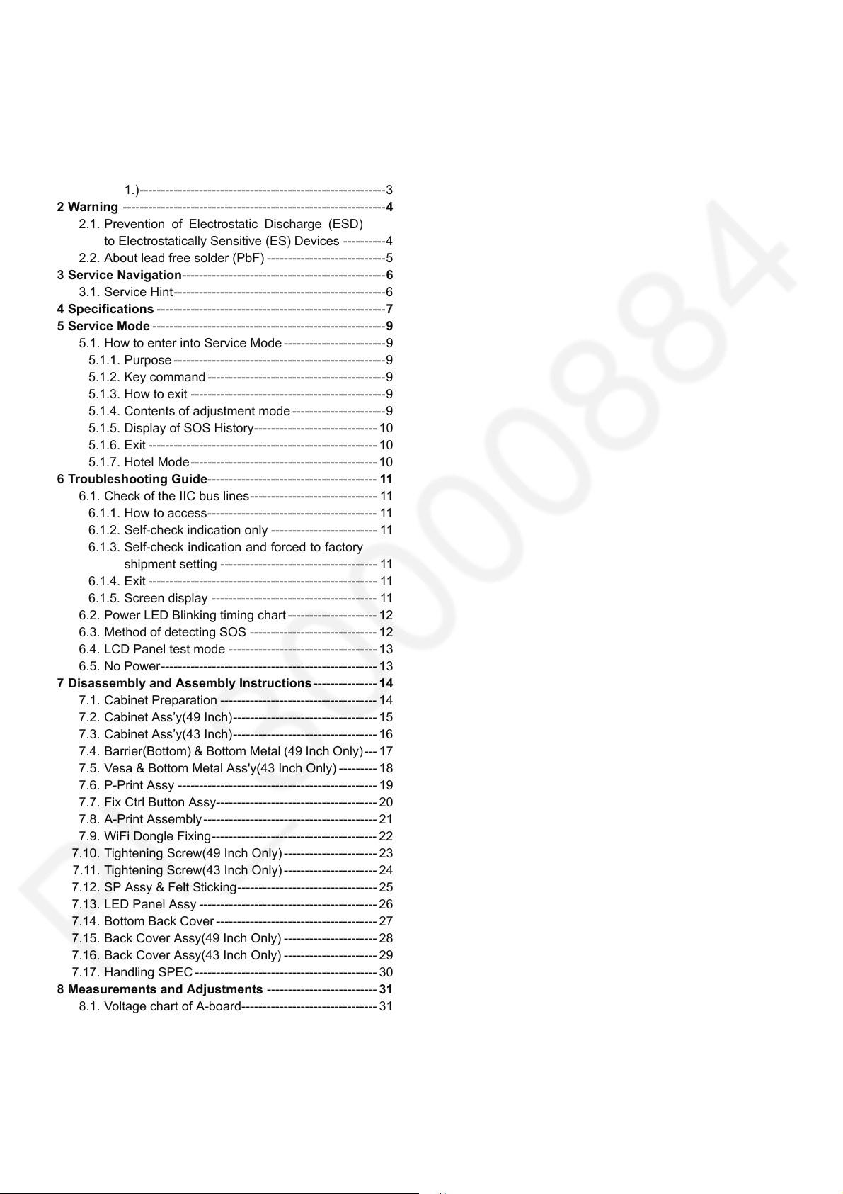
1.1.2. Leakage Current Hot Check (See Figure 1.)
1. Plug the AC cord directly into the AC outlet. Do not use
an isolation transformer for this check.
2. Connect a 1.5kohm, 10 watts resistor, in parallel with a
0.15F capacitors, between each exposed metallic part
on the set and a good earth ground such as a water pipe,
as shown in Figure 1.
3. Use an AC voltmeter, with 1000 ohms/volt or more
sensitivity, to measure the potential across the resistor.
4. Check each exposed metallic part, and measure the
voltage at each point.
5. Reverse the AC plug in the AC outlet and repeat each of
the above measurements.
6. The potential at any point should not exceed 0.75 volts
RMS. A leakage current tester (Simpson Model 229 or
equivalent) may be used to make the hot checks, leakage
current must not exceed 1/2 milliamp. In case a
measurement is outside of the limits specified, there is a
possibility of a shock hazard, and the equipment should
be repaired and rechecked before it is returned to the
customer.
Figure 1
3
Page 4
TH-43/49CS630X
2Warning
2.1. Prevention of Electrostatic Discharge (ESD) to Electrostatically Sensitive (ES) Devices
Some semiconductor (solid state) devices can be damaged easily by static electricity. Such components commonly are called
Electrostatically Sensitive (ES) Devices. Examples of typical ES devices are integrated circuits and some field-effect transistors and
semiconductor [chip] components. The following techniques should be used to help reduce the incidence of component damage
caused by electrostatic discharge (ESD).
1. Immediately before handling any semiconductor component or semiconductor-equipped assembly, drain off any ESD on your
body by touching a known earth ground. Alternatively, obtain and wear a commercially available discharging ESD wrist strap,
which should be removed for potential shock reasons prior to applying power to the unit under test.
2. After removing an electrical assembly equipped with ES devices, place the assembly on a conductive surface such as
aluminum foil, to prevent electrostatic charge buildup or exposure of the assembly.
3. Use only a grounded-tip soldering iron to solder or unsolder ES devices.
4. Use only an anti-static solder removal device. Some solder removal devices not classified as [anti-static (ESD protected)] can
generate electrical charge sufficient to damage ES devices.
5. Do not use freon-propelled chemicals. These can generate electrical charges sufficient to damage ES devices.
6. Do not remove a replacement ES device from its protective package until immediately before you are ready to install it. (Most
replacement ES devices are packaged with leads electrically shorted together by conductive foam, aluminum foil or
comparable conductive material).
7. Immediately before removing the protective material from the leads of a replacement ES device, touch the protective material
to the chassis or circuit assembly into which the device will be installed.
Caution
Be sure no power is applied to the chassis or circuit, and observe all other safety precautions.
8. Minimize bodily motions when handling unpackaged replacement ES devices. (Otherwise ham less motion such as the
brushing together of your clothes fabric or the lifting of your foot from a carpeted floor can generate static electricity (ESD)
sufficient to damage an ES device).
4
Page 5
TH-43/49CS630X
2.2. About lead free solder (PbF)
Note: Lead is listed as (Pb) in the periodic table of elements.
In the information below, Pb will refer to Lead solder, and PbF will refer to Lead Free Solder.
The Lead Free Solder used in our manufacturing process and discussed below is (Sn+Ag+Cu).
That is Tin (Sn), Silver (Ag) and Copper (Cu) although other types are available.
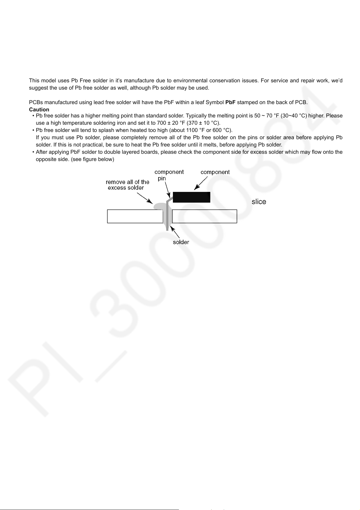
This model uses Pb Free solder in it’s manufacture due to environmental conservation issues. For service and repair work, we’d
suggest the use of Pb free solder as well, although Pb solder may be used.
PCBs manufactured using lead free solder will have the PbF within a leaf Symbol PbF stamped on the back of PCB.
Caution
• Pb free solder has a higher melting point than standard solder. Typically the melting point is 50 ~ 70 °F (30~40 °C) higher. Please
use a high temperature soldering iron and set it to 700 ± 20 °F (370 ± 10 °C).
• Pb free solder will tend to splash when heated too high (about 1100 °F or 600 °C).
If you must use Pb solder, please completely remove all of the Pb free solder on the pins or solder area before applying Pb
solder. If this is not practical, be sure to heat the Pb free solder until it melts, before applying Pb solder.
• After applying PbF solder to double layered boards, please check the component side for excess solder which may flow onto the
opposite side. (see figure below)
5
Page 6
TH-43/49CS630X
3 Service Navigation
3.1. Service Hint
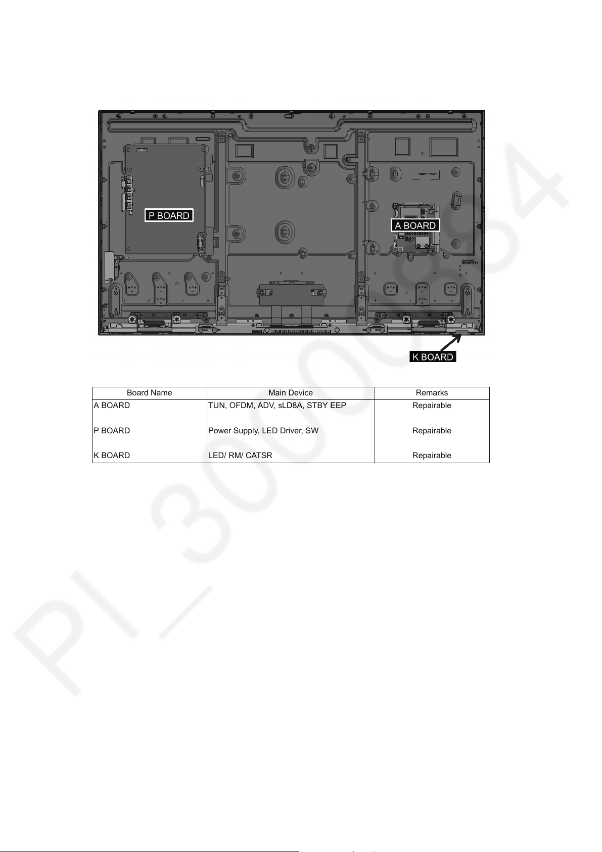
Board Name Main Device Remarks
A BOARD TUN, OFDM, ADV, sLD8A, STBY EEP Repairable
P BOARD Power Supply, LED Driver, SW Repairable
K BOARD LED/ RM/ CATSR Repairable
6
Page 7
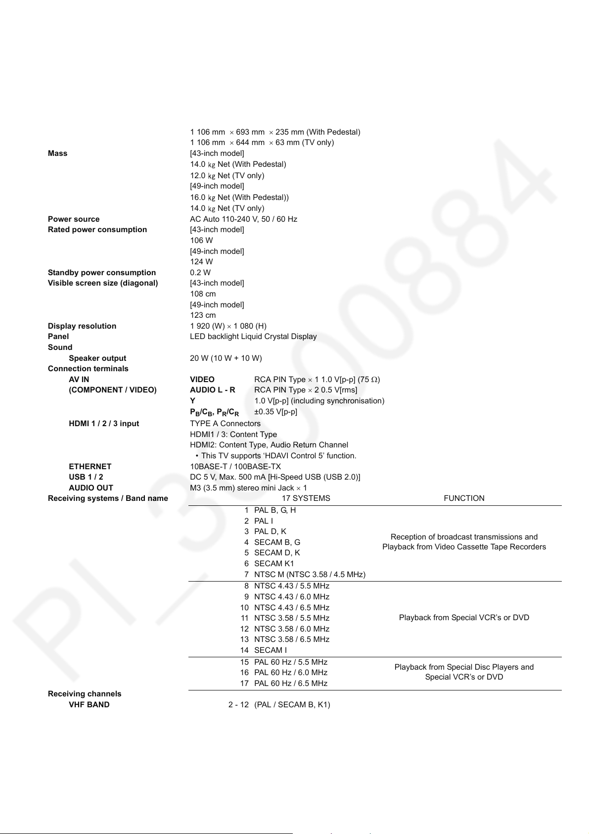
4 Specifications
Dimensions (W H D) [43-inch model]
974 mm 618 mm 194 mm (With Pedestal)
974 mm 569 mm 63 mm (TV only)
[49-inch model]
1 106 mm 693 mm 235 mm (With Pedestal)
1 106 mm 644 mm 63 mm (TV only)
Mass [43-inch model]
14.0 Net (With Pedestal)
12.0 Net (TV only)
[49-inch model]
16.0 Net (With Pedestal))
14.0 Net (TV only)
Power source AC Auto 110-240 V, 50 / 60 Hz
Rated power consumption [43-inch model]
106 W
[49-inch model]
124 W
Standby power consumption 0.2 W
Visible screen size (diagonal) [43-inch model]
108 cm
[49-inch model]
123 cm
Display resolution 1 920 (W) 1 080 (H)
Panel LED backlight Liquid Crystal Display
Sound
Speaker output 20 W (10 W + 10 W)
Connection terminals
AV I N VI D EO RCA PIN Type 1 1.0 V[p-p] (75 )
(COMPONENT / VIDEO) AUDIO L - R RCA PIN Type 2 0.5 V[rms]
Y 1.0 V[p-p] (including synchronisation)
P
, PR/C
B/CB
HDMI 1 / 2 / 3 input TYPE A Connectors
HDMI1 / 3: Content Type
HDMI2: Content Type, Audio Return Channel
• This TV supports ‘HDAVI Control 5’ function.
ETHERNET 10BASE-T / 100BASE-TX
USB 1 / 2 DC 5 V, Max. 500 mA [Hi-Speed USB (USB 2.0)]
AUDIO OUT M3 (3.5 mm) stereo mini Jack 1
Receiving systems / Band name 17 SYSTEMS FUNCTION
Receiving channels
VHF BAND 2 - 12 (PAL / SECAM B, K1)
±0.35 V[p-p]
R
1 PAL B, G, H
2PAL I
3PAL D, K
4 SECAM B, G
5SECAM D, K
6 SECAM K1
7
NTSC M (NTSC 3.58 / 4.5 MHz)
8 NTSC 4.43 / 5.5 MHz
9 NTSC 4.43 / 6.0 MHz
10 NTSC 4.43 / 6.5 MHz
11 NTSC 3.58 / 5.5 MHz
12 NTSC 3.58 / 6.0 MHz
13 NTSC 3.58 / 6.5 MHz
14 SECAM I
15 PAL 60 Hz / 5.5 MHz
16 PAL 60 Hz / 6.0 MHz
17 PAL 60 Hz / 6.5 MHz
0 - 12 (PAL B AUST.)
1 - 9 (PAL B N.Z.)
1 - 12 (PAL / SECAM D)
1 - 12 (NTSC M Japan)
2 - 13 (NTSC M USA)
Reception of broadcast transmissions and
Playback from Video Cassette Tape Recorders
Playback from Special VCR’s or DVD
Playback from Special Disc Players and
Special VCR’s or DVD
TH-43/49CS630X
7
Page 8
TH-43/49CS630X
UHF BAND 21 - 69 (PAL G, H, I / SECAM G, K, K1)
28 - 69 (PAL B AUST.)
13 - 57 (PAL D, K)
13 - 62 (NTSC M Japan)
14 - 69 (NTSC M USA)
CATV S1 - S20 (OSCAR)
1 - 125 (USA CATV)
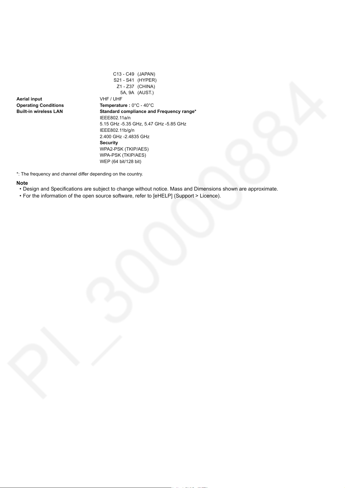
C13 - C49 (JAPAN)
S21 - S41 (HYPER)
Z1 - Z37 (CHINA)
5A, 9A (AUST.)
Aerial input VHF / UHF
Operating Conditions Temperature : 0°C - 40°C
Built-in wireless LAN Standard compliance and Frequency range*
IEEE802.11a/n
5.15 GHz -5.35 GHz, 5.47 GHz -5.85 GHz
IEEE802.11b/g/n
2.400 GHz -2.4835 GHz
Security
WPA2-PSK (TKIP/AES)
WPA-PSK (TKIP/AES)
WEP (64 bit/128 bit)
*: The frequency and channel differ depending on the country.
Note
• Design and Specifications are subject to change without notice. Mass and Dimensions shown are approximate.
• For the information of the open source software, refer to [eHELP] (Support > Licence).
8
Page 9
TH-43/49CS630X
5 Service Mode
5.1. How to enter into Service Mode
5.1.1. Purpose
After exchange parts, check and adjust the contents of adjustment mode.
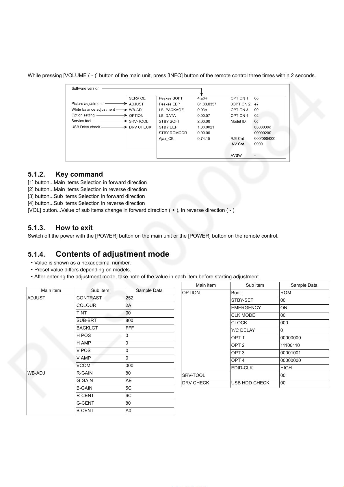
While pressing [VOLUME ( - )] button of the main unit, press [INFO] button of the remote control three times within 2 seconds.
5.1.2. Key command
[1] button...Main items Selection in forward direction
[2] button...Main items Selection in reverse direction
[3] button...Sub items Selection in forward direction
[4] button...Sub items Selection in reverse direction
[VOL] button...Value of sub items change in forward direction ( + ), in reverse direction ( - )
5.1.3. How to exit
Switch off the power with the [POWER] button on the main unit or the [POWER] button on the remote control.
5.1.4. Contents of adjustment mode
• Value is shown as a hexadecimal number.
• Preset value differs depending on models.
• After entering the adjustment mode, take note of the value in each item before starting adjustment.
Main item Sub item Sample Data
ADJUST CONTRAST 252
COLOUR 2A
TINT 00
SUB-BRT 800
BACKLGT FFF
H POS 0
H AMP 0
V POS 0
V AMP 0
VCOM 000
WB-ADJ R-GAIN 80
G-GAIN AE
B-GAIN 5C
R-CENT 6C
G-CENT 80
B-CENT A0
Main item Sub item Sample Data
OPTION Boot ROM
STBY-SET 00
EMERGENCY ON
CLK MODE 00
CLOCK 000
Y/C DELAY 0
OPT 1 00000000
OPT 2 11100110
OPT 3 00001001
OPT 4 00000000
EDID-CLK HIGH
SRV-TOOL 00
DRV CHECK USB HDD CHECK 00
9
Page 10
TH-43/49CS630X
5.1.5. Display of SOS History
SOS History (Number of LED blinking) indication.
From left side; Last SOS, before Last, three occurrence before, 2nd occurrence after shipment, 1st occurrence after shipment.
This indication except 2nd and 1st occurrence after shipment will be cleared by [Self-check indication and forced to factory
shipment setting].
5.1.6. Exit
1. Disconnect the AC cord from wall outlet.
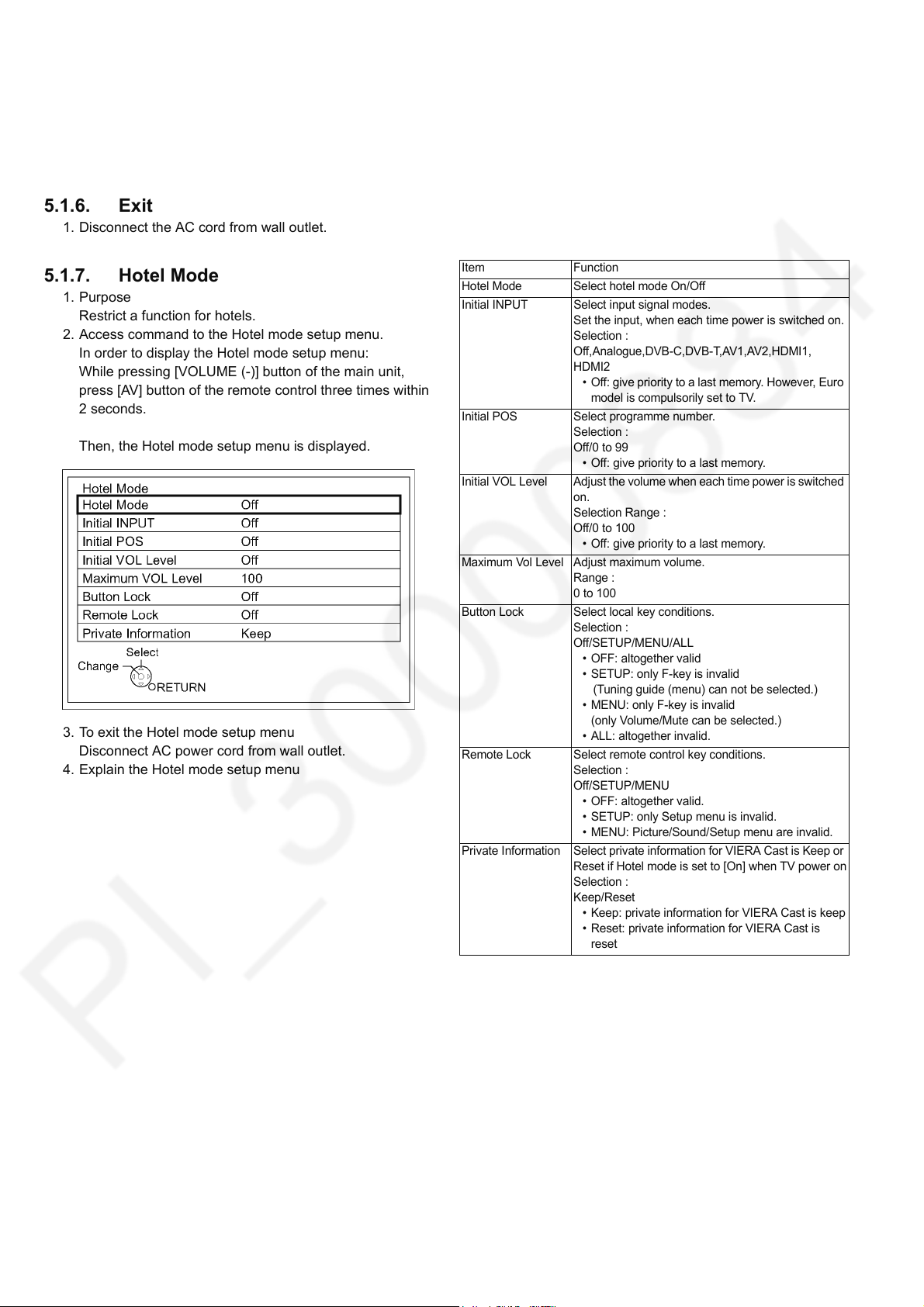
5.1.7. Hotel Mode
1. Purpose
Restrict a function for hotels.
2. Access command to the Hotel mode setup menu.
In order to display the Hotel mode setup menu:
While pressing [VOLUME (-)] button of the main unit,
press [AV] button of the remote control three times within
2 seconds.
Then, the Hotel mode setup menu is displayed.
3. To exit the Hotel mode setup menu
Disconnect AC power cord from wall outlet.
4. Explain the Hotel mode setup menu
Item Function
Hotel Mode Select hotel mode On/Off
Initial INPUT Select input signal modes.
Set the input, when each time power is switched on.
Selection :
Off,Analogue,DVB-C,DVB-T,AV1,AV2,HDMI1,
HDMI2
• Off: give priority to a last memory. However, Euro
model is compulsorily set to TV.
Initial POS Select programme number.
Selection :
Off/0 to 99
• Off: give priority to a last memory.
Initial VOL Level Adjust the volume when each time power is switched
on.
Selection Range :
Off/0 to 100
• Off: give priority to a last memory.
Maximum Vol Level Adjust maximum volume.
Range :
0 to 100
Button Lock Select local key conditions.
Selection :
Off/SETUP/MENU/ALL
• OFF: altogether valid
• SETUP: only F-key is invalid
(Tuning guide (menu) can not be selected.)
• MENU: only F-key is invalid
(only Volume/Mute can be selected.)
• ALL: altogether invalid.
Remote Lock Select remote control key conditions.
Selection :
Off/SETUP/MENU
• OFF: altogether valid.
• SETUP: only Setup menu is invalid.
• MENU: Picture/Sound/Setup menu are invalid.
Private Information Select private information for VIERA Cast is Keep or
Reset if Hotel mode is set to [On] when TV power on
Selection :
Keep/Reset
• Keep: private information for VIERA Cast is keep
• Reset: private information for VIERA Cast is
reset
10
Page 11
TH-43/49CS630X
6 Troubleshooting Guide
Use the self-check function to test the unit.
1. Checking the IIC bus lines
2. Power LED Blinking timing
6.1. Check of the IIC bus lines
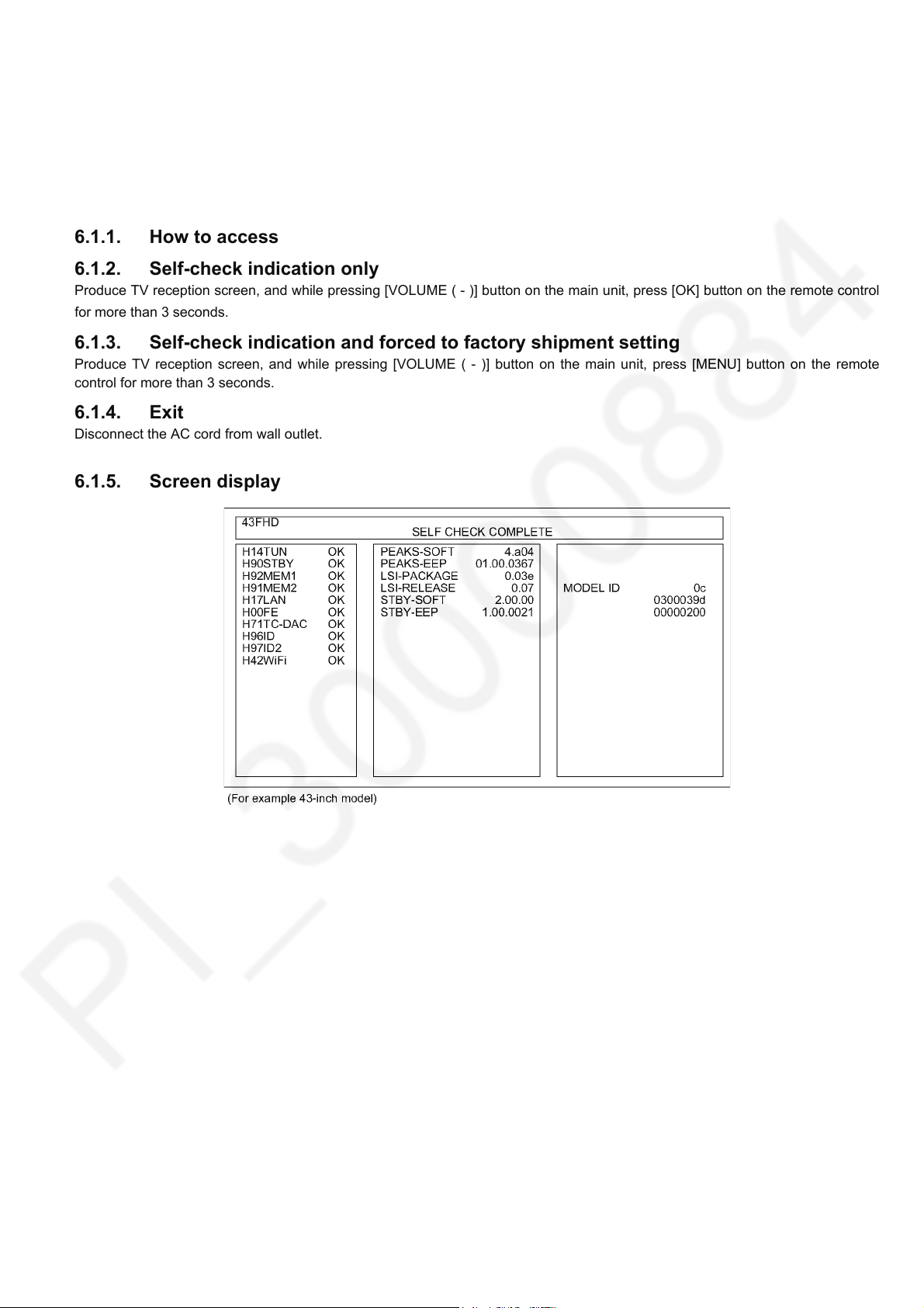
6.1.1. How to access
6.1.2. Self-check indication only
Produce TV reception screen, and while pressing [VOLUME ( - )] button on the main unit, press [OK] button on the remote control
for more than 3 seconds.
6.1.3. Self-check indication and forced to factory shipment setting
Produce TV reception screen, and while pressing [VOLUME ( - )] button on the main unit, press [MENU] button on the remote
control for more than 3 seconds.
6.1.4. Exit
Disconnect the AC cord from wall outlet.
6.1.5. Screen display
11
Page 12
TH-43/49CS630X
6.2. Power LED Blinking timing chart
1. Subject
Information of LED Flashing timing chart.
2. Contents
When an abnormality occurs, the protection circuit will operate and reset the unit to stand by mode. During this time, the
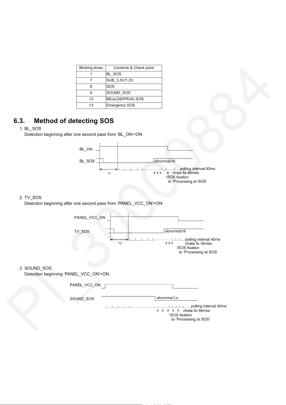
defective block can be identified by the number of blinking times of the Power LED on the front panel of the unit as follow:
Blinking times Contents & Check point
1 BL_SOS
7 SUB_3.3V/1.2V
8SOS
9 SOUND_SOS
12 BE(sLD8/PRO4) SOS
13 Emergency SOS
6.3. Method of detecting SOS
1. BL_SOS
Detection beginning after one second pass from ‘BL_ON’=ON
2. TV_SOS
Detection beginning after one second pass from ‘PANEL_VCC_ON’=ON
3. SOUND_SOS
Detection beginning ‘PANEL_VCC_ON’=ON
12
Page 13
TH-43/49CS630X
6.4. LCD Panel test mode
Purpose:
To find the possible failure point where in LCD Panel or Printed Circuit Board when the abnormal picture is displayed.
How to Enter:
While pressing [VOLUME ( - )] button of the main unit, press [OPTION] button of the remote control three times within 2
seconds.
How to Exit:
Disconnect AC plug from wall outlet.
How to confirm:
If the abnormal picture is displayed, go into LCD Panel test mode to display the several test patterns.
And then, judge by the following method.
Still abnormal picture is displayed: The cause must be in LCD Panel.
Normal picture is displayed: The cause must be in A board.
Remarks:
The test pattern is created by the circuit in LCD Panel.
In LCD Panel test mode, this test pattern is displayed unaffected by signal processing for RF or input signal.
If the normal picture is displayed, LCD Panel must be okay and the cause of failure must be in A board.
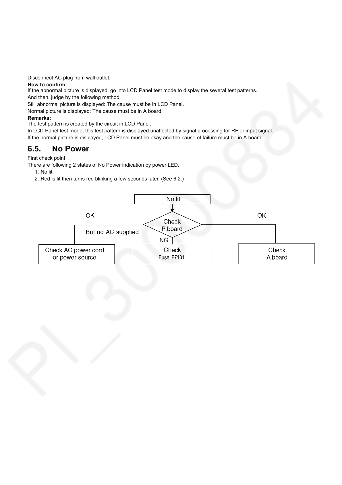
6.5. No Power
First check point
There are following 2 states of No Power indication by power LED.
1. No lit
2. Red is lit then turns red blinking a few seconds later. (See 6.2.)
13
Page 14
TH-43/49CS630X
7 Disassembly and Assembly Instructions
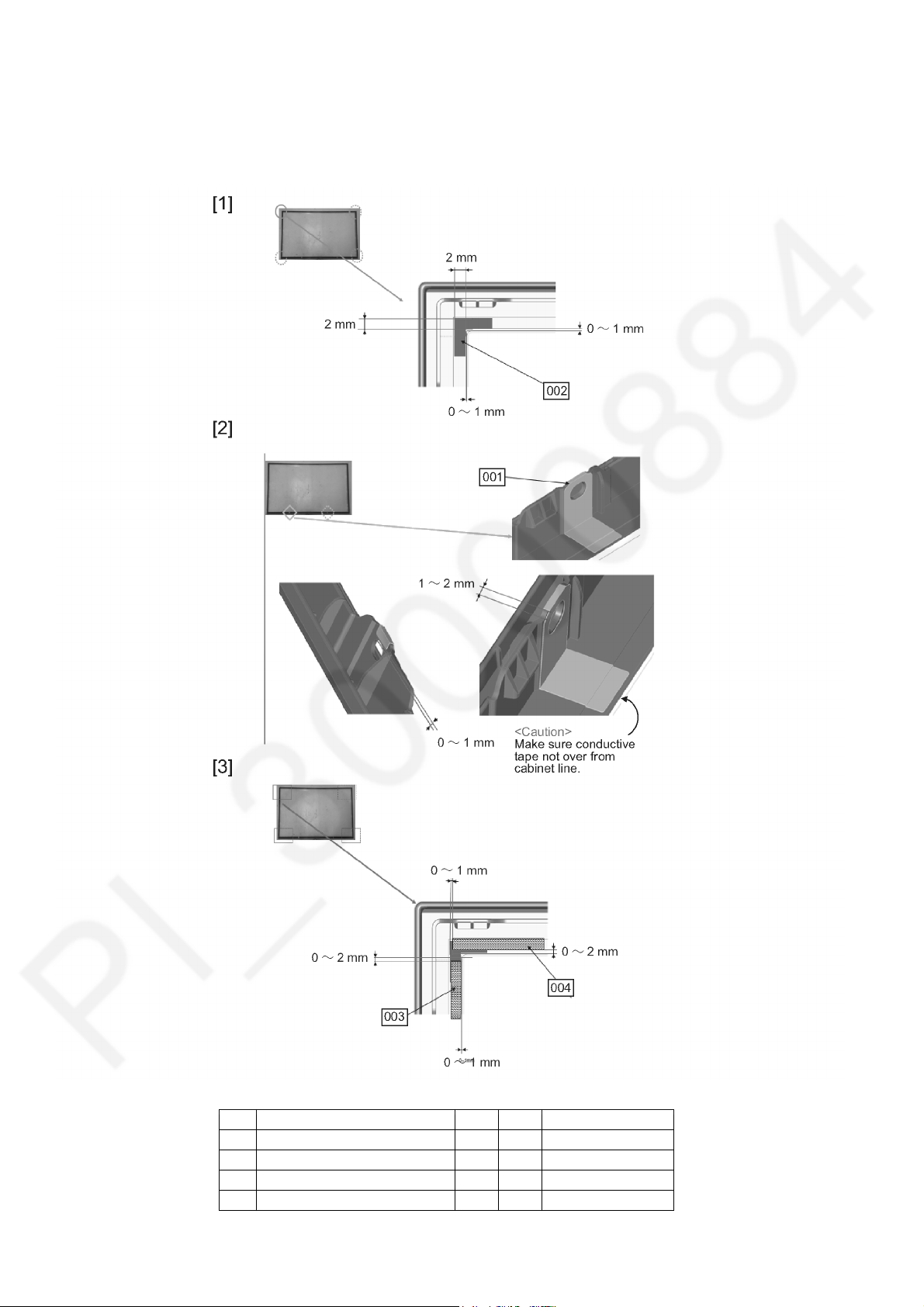
7.1. Cabinet Preparation
1. Stick all conductive tape and AL tape follow the position and tolerance given below.
2. Sequence arrangement procedure follow this method [1][2][3]
No Description Qty UOM Remarks
001 AL TAPE (BOTTOM) 2 PC
002 AL TAPE (CORNER) 4 PC
003 CONDUCTIVE TAPE 2 PC
004 CONDUCTIVE TAPE 2 PC
14
Page 15
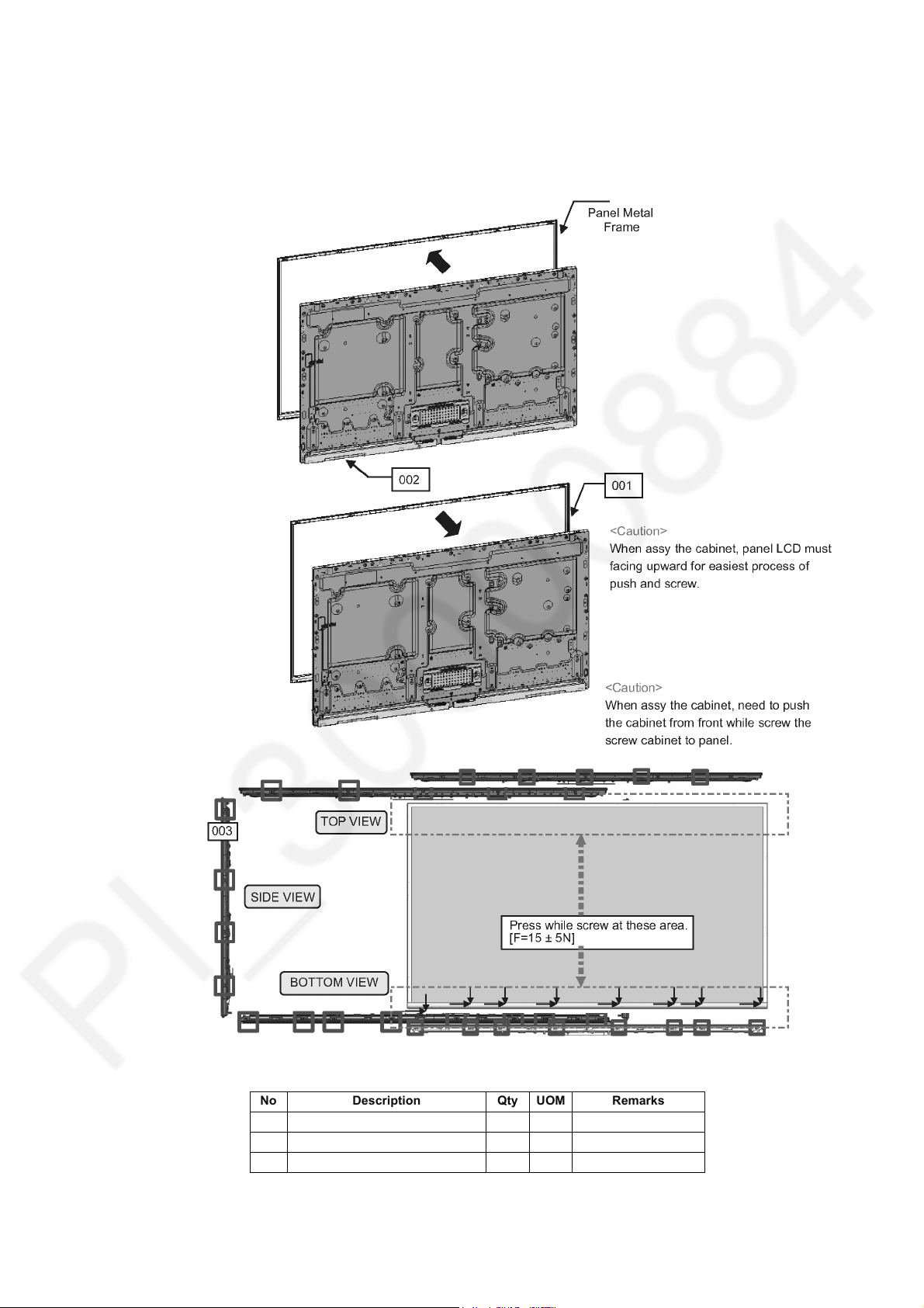
7.2. Cabinet Ass’y(49 Inch)
1. PANEL METAL FRAME need to remove from panel by unscrew all around frame.
2. Panel must fit to CABINET first before screw.
3. Screw all around CABINET position follow the torque given.
4. TOP and BOTTOM area must need to push during screw to prevent from gap uneven.
TH-43/49CS630X
No Description Qty UOM Remarks
001 CABINET ASSY 1 PC
002 LCD PANEL 1 PC
003 SCREW(PANEL) 21 PC 5-7Kgf.cm
15
Page 16
TH-43/49CS630X
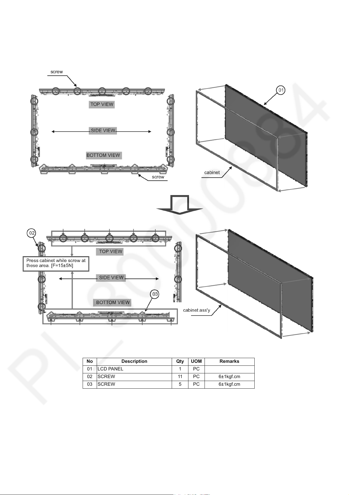
7.3. Cabinet Ass’y(43 Inch)
1. Open and remove screws (16 pcs) from each side of panel.
2. Remove attached cabinet frame from panel.
3. Install new cabinet ass'y and fix with new screws.
No Description Qty UOM Remarks
01 LCD PANEL 1 PC
02 SCREW 11 PC 6±1kgf.cm
03 SCREW 5 PC 6±1kgf.cm
16
Page 17
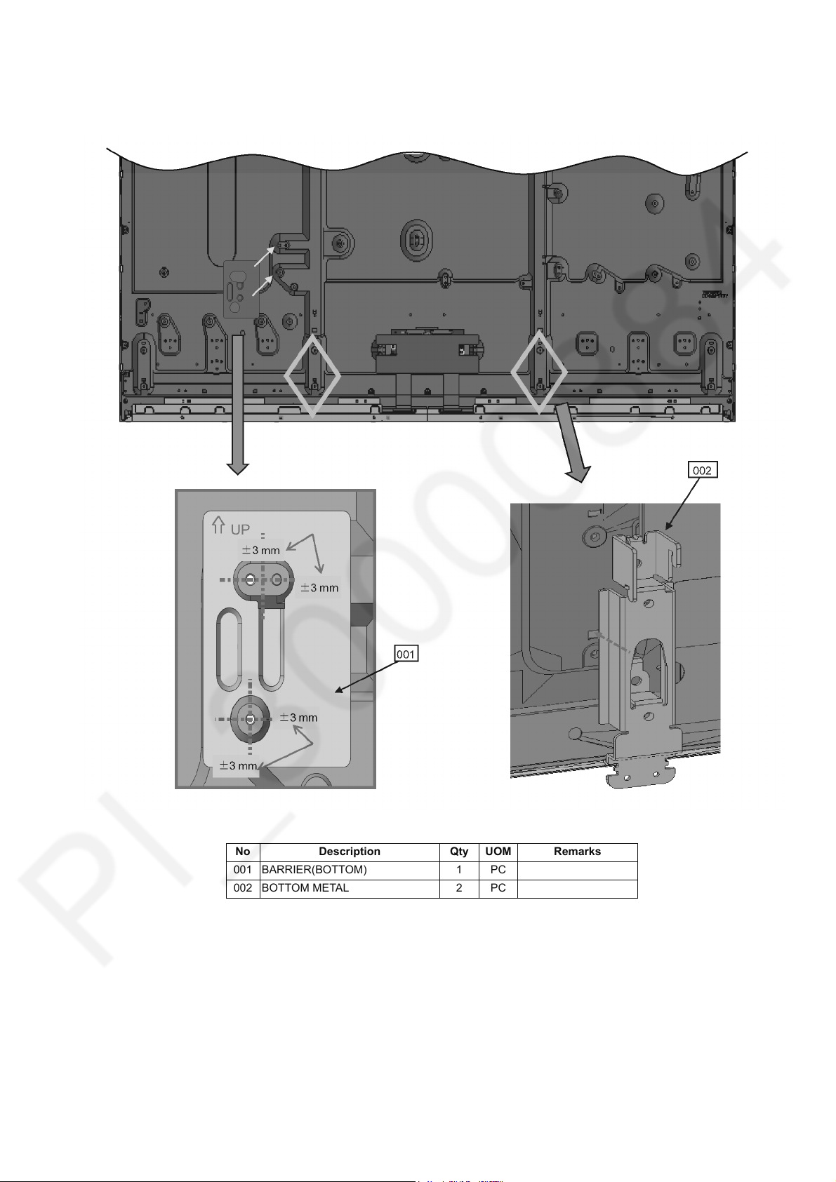
7.4. Barrier(Bottom) & Bottom Metal (49 Inch Only)
1. Stick BARRIER follow according the picture.
2. Fix BTM METAL to panel.
TH-43/49CS630X
No Description Qty UOM Remarks
001 BARRIER(BOTTOM) 1 PC
002 BOTTOM METAL 2 PC
17
Page 18
TH-43/49CS630X
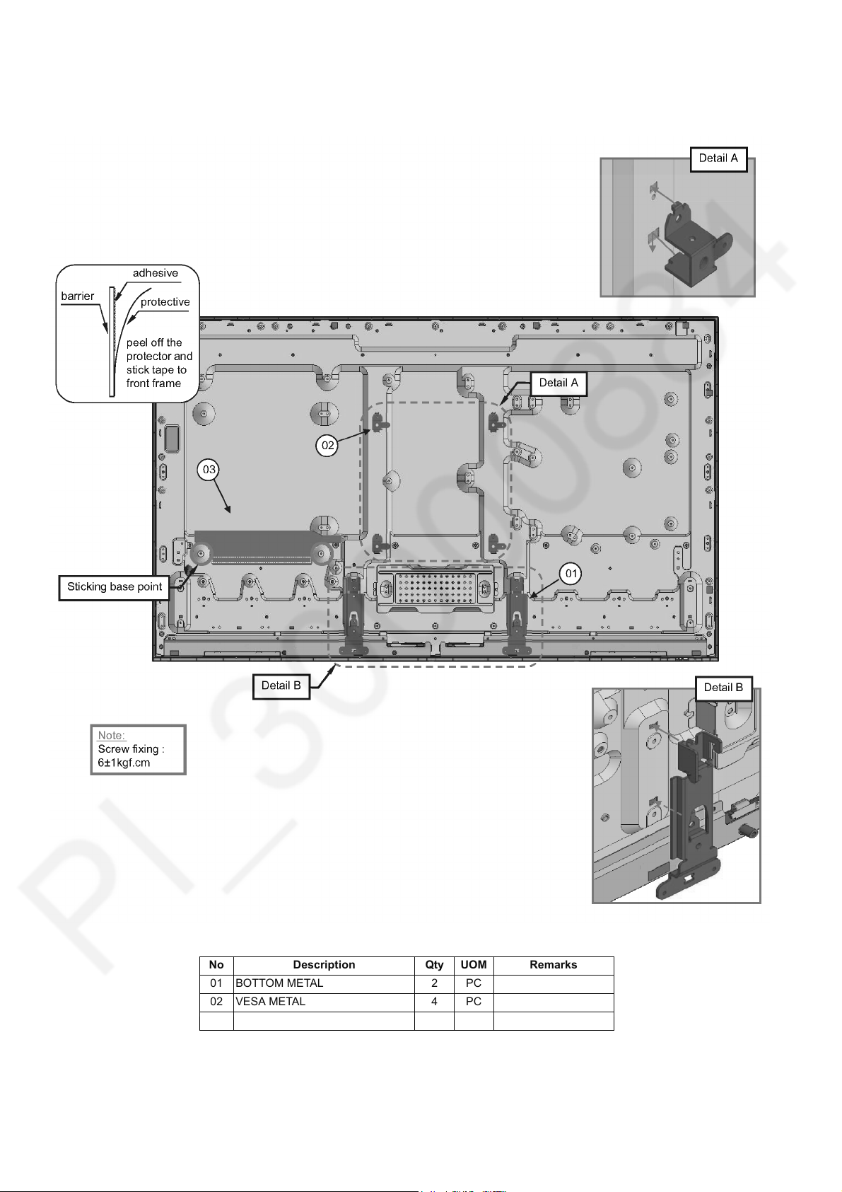
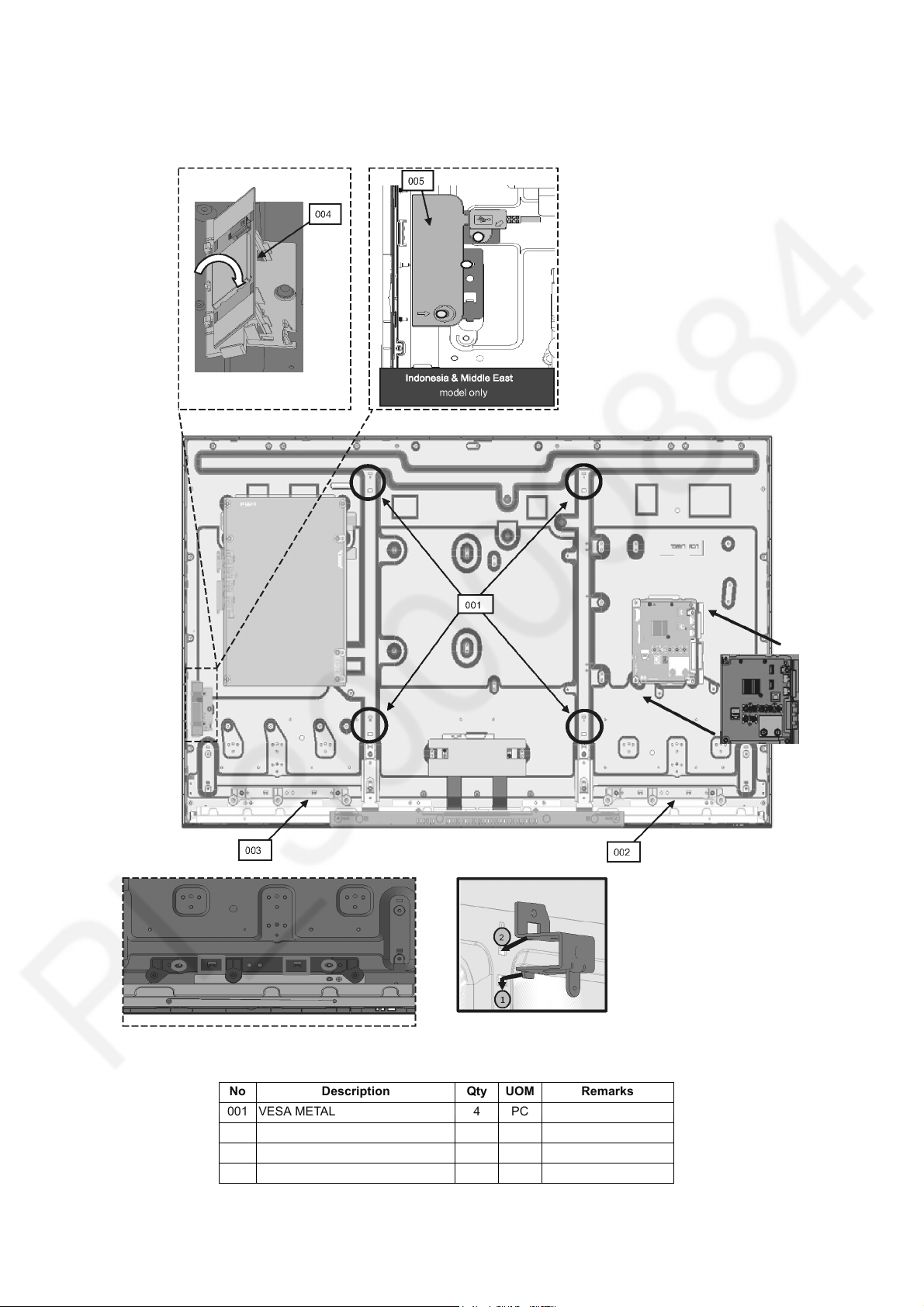
7.5. Vesa & Bottom Metal Ass'y(43 Inch Only)
1. Fix barrier.
2. Install vesa metal & bottom metal.
No Description Qty UOM Remarks
01 BOTTOM METAL 2 PC
02 VESA METAL 4 PC
03 P-PCB BARRIER 1 PC
18
Page 19
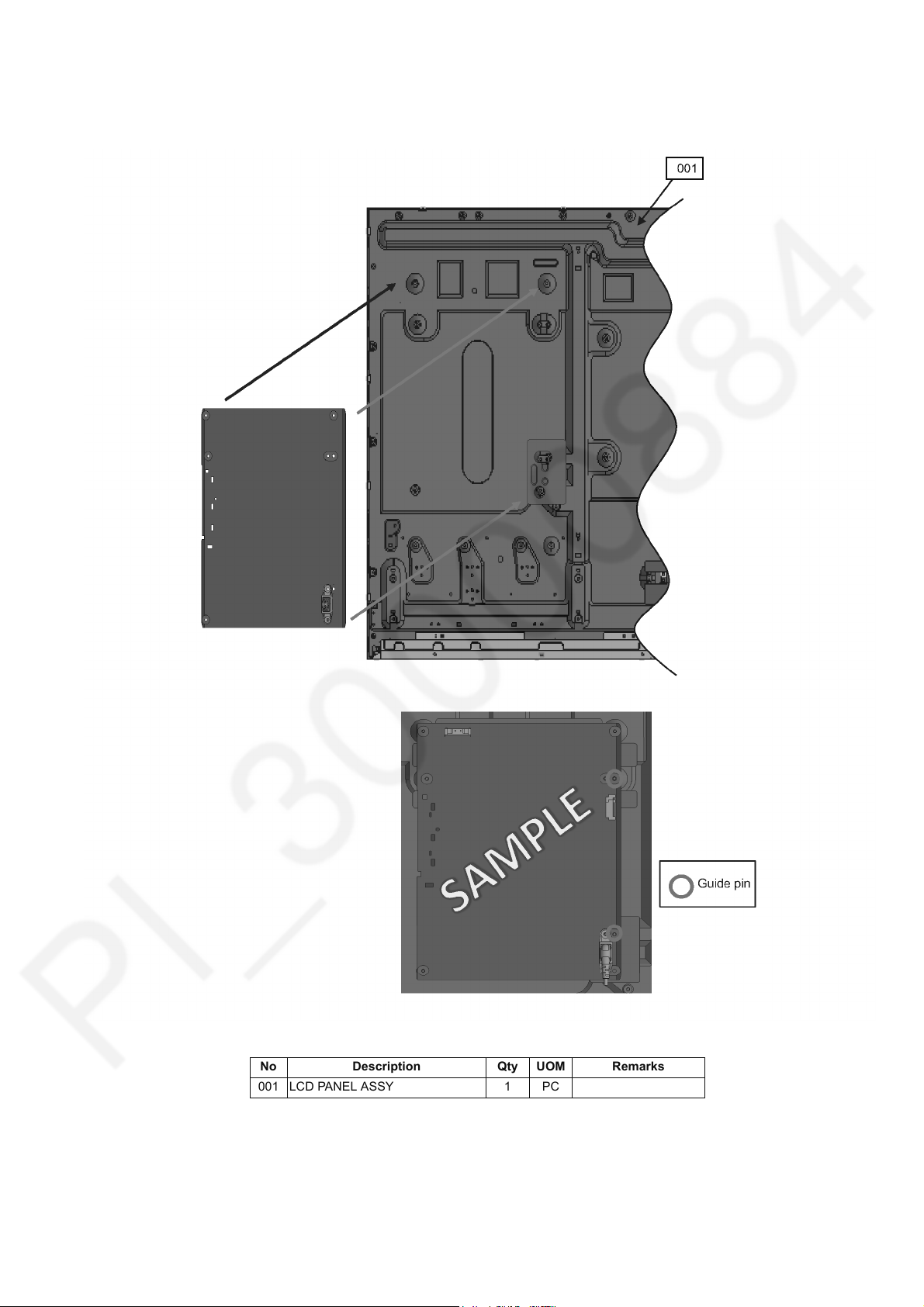
7.6. P-Print Assy
1. Fixing P-PRINT to panel.
2. Make sure hole are fully insert by guide pin.
TH-43/49CS630X
No Description Qty UOM Remarks
001 LCD PANEL ASSY 1 PC
19
Page 20
TH-43/49CS630X
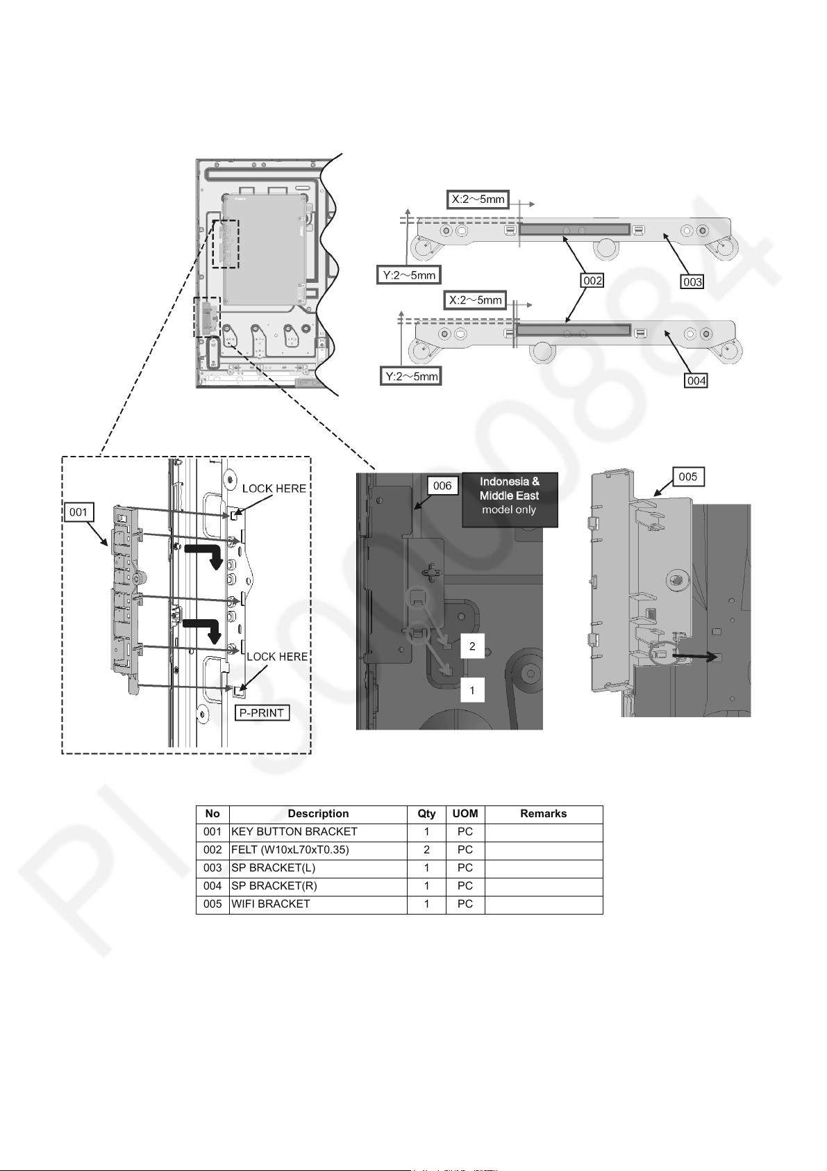
7.7. Fix Ctrl Button Assy
1. Fix KEY BUTTON BRACKET to P-PRINT.
2. Insert WIFI BRACKET to panel.
No Description Qty UOM Remarks
001 KEY BUTTON BRACKET 1 PC
002 FELT (W10xL70xT0.35) 2 PC
003 SP BRACKET(L) 1 PC
004 SP BRACKET(R) 1 PC
005 WIFI BRACKET 1 PC
20
Page 21
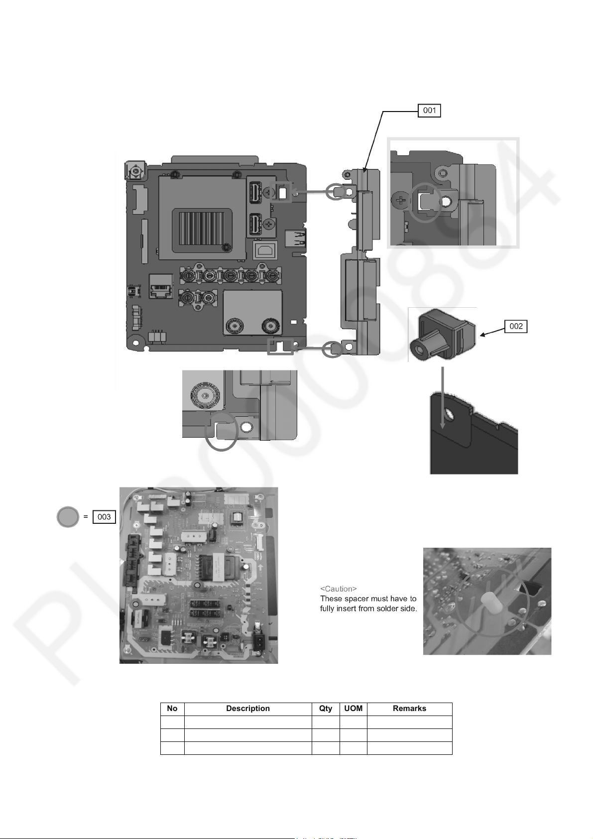
7.8. A-Print Assembly
1. Fixing SIDE AV BRACKET to A-Print follow guide pin and rib hole.
2. Fix A-PCB BRACKET to A-Print follow the picture below.
TH-43/49CS630X
No Description Qty UOM Remarks
001 SIDE_AV_BRACKET 1 PC
002 A-PCB BRACKET 1 PC
003 SPACER P-PCB 3 PC
21
Page 22
TH-43/49CS630X
7.9. WiFi Dongle Fixing
1. Insert VESA METAL to panel follow the step diagram as below.
2. Put A-Print to panel and make sure guide pin at boss is lock to A-Print.
No Description Qty UOM Remarks
001 VESA METAL 4 PC
002 SP BRACKET(L) 1 PC
003 SP BRACKET(R) 1 PC
004 WIFI MODULE 1 PC
22
Page 23
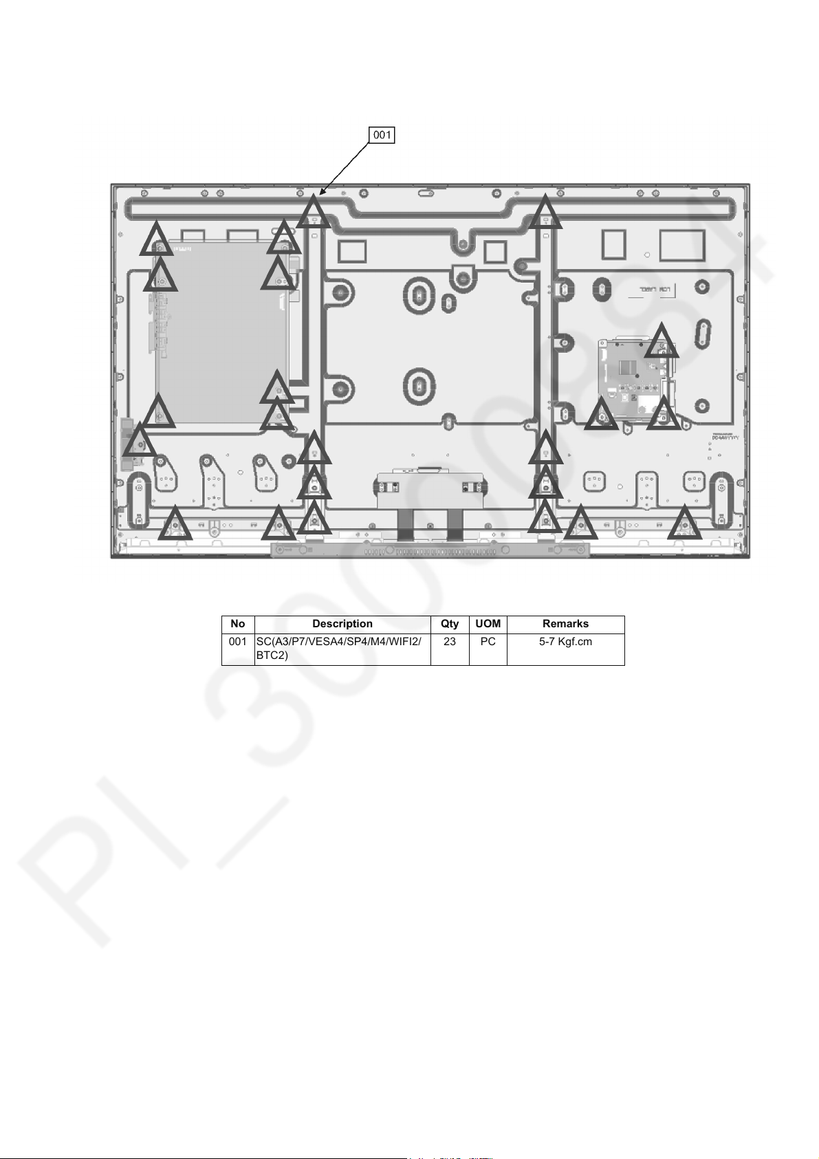
7.10. Tightening Screw(49 Inch Only)
1. Screw all part follow the picture shown below.
TH-43/49CS630X
No Description Qty UOM Remarks
001 SC(A3/P7/VESA4/SP4/M4/WIFI2/
BTC2)
23 PC 5-7 Kgf.cm
23
Page 24
TH-43/49CS630X
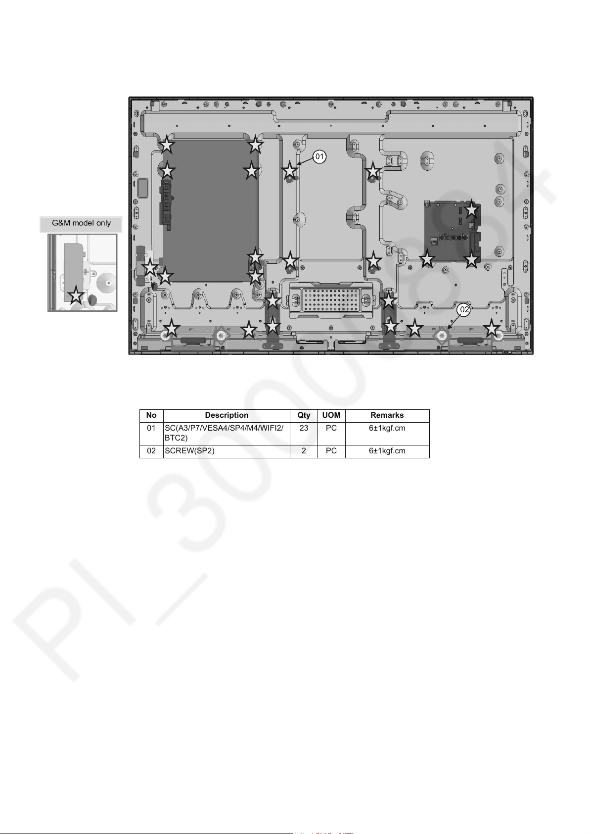
7.11. Tightening Screw(43 Inch Only)
1. Fix screws with torque given.
No Description Qty UOM Remarks
01 SC(A3/P7/VESA4/SP4/M4/WIFI2/
BTC2)
02 SCREW(SP2) 2 PC 6±1kgf.cm
23 PC 6±1kgf.cm
24
Page 25
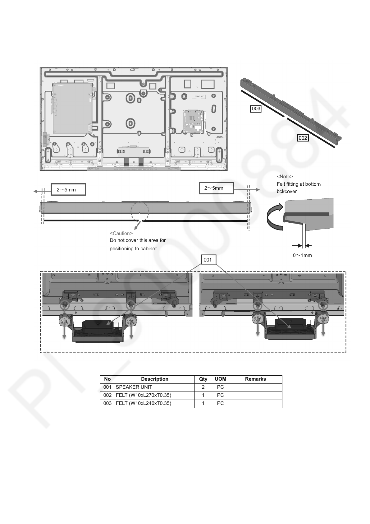
7.12. SP Assy & Felt Sticking
1. Insert P-Print and A-Print board at Panel.
2. Fixing all screw at panel,bracket and metal part.
TH-43/49CS630X
No Description Qty UOM Remarks
001 SPEAKER UNIT 2 PC
002 FELT (W10xL270xT0.35) 1 PC
003 FELT (W10xL240xT0.35) 1 PC
25
Page 26
TH-43/49CS630X
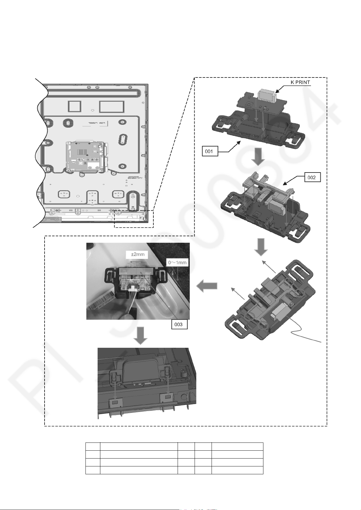
7.13. LED Panel Assy
1. Attach K-PRINT on LED PANEL CASE.
2. Attach LED PANEL.
3. Slide LED PANEL & confirm fitting of click.
4. Stick the SPONGE to LED PANEL ASSY.
5. Attach to CABINET & confirm click of fitting.
No Description Qty UOM Remarks
001 LED PANEL CASE 1 PC
002 LED PANEL 1 PC
003 SPONGE(LED) 1 PC
26
Page 27
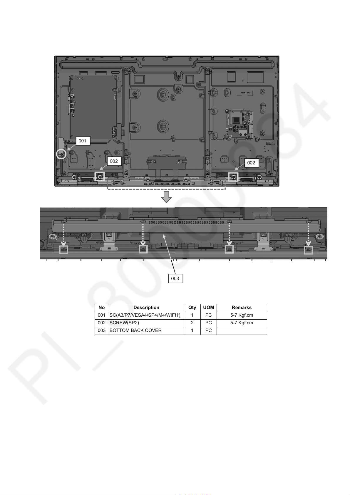
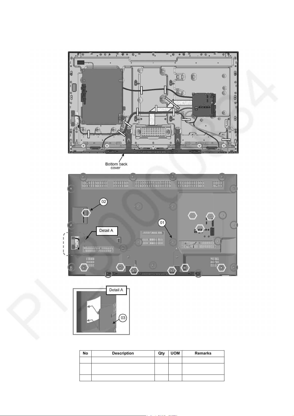
7.14. Bottom Back Cover
1. Fix screw to all part follow below display.
TH-43/49CS630X
No Description Qty UOM Remarks
001 SC(A3/P7/VESA4/SP4/M4/WIFI1) 1 PC 5-7 Kgf.cm
002 SCREW(SP2) 2 PC 5-7 Kgf.cm
003 BOTTOM BACK COVER 1 PC
27
Page 28
TH-43/49CS630X
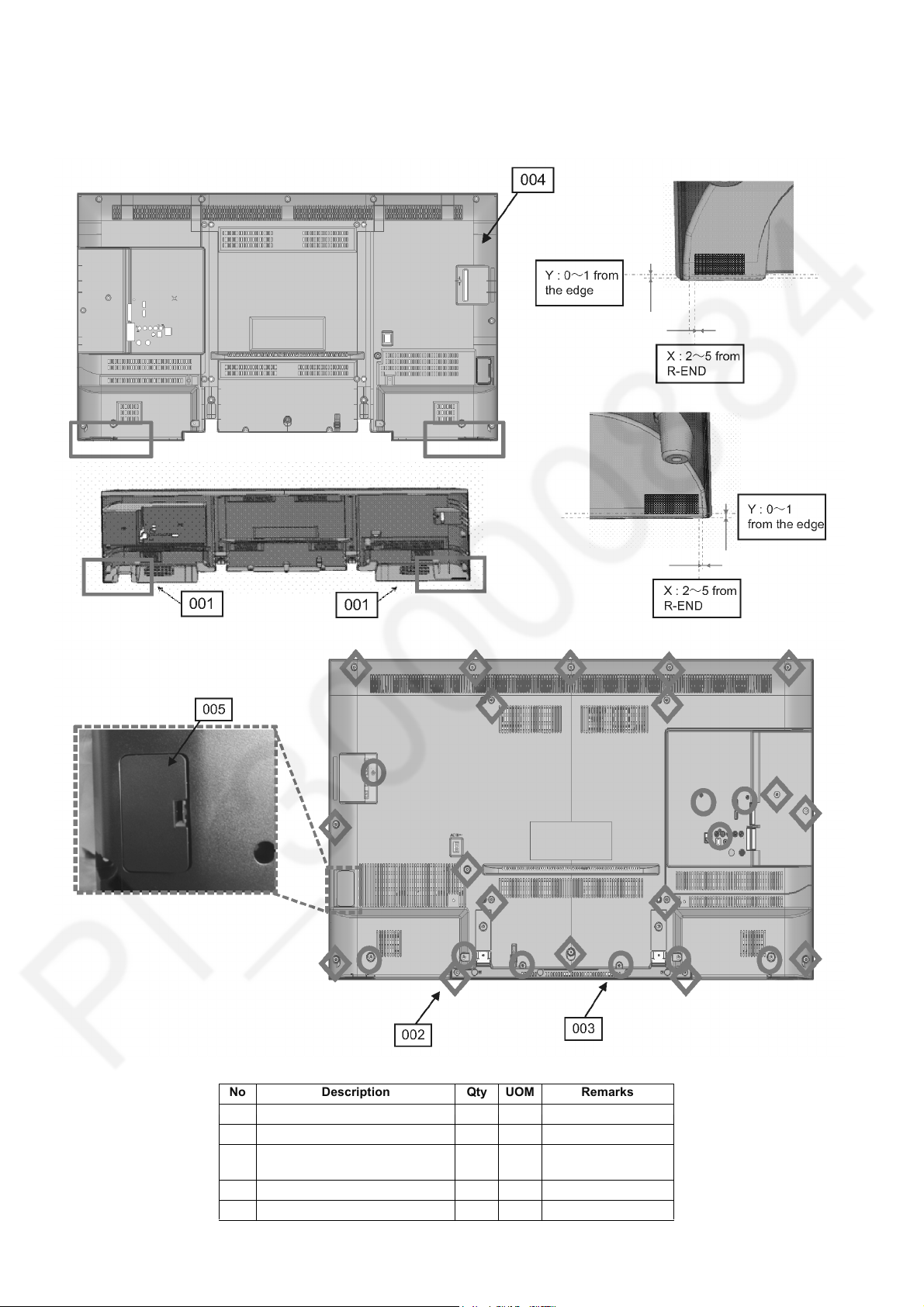
7.15. Back Cover Assy(49 Inch Only)
1. Stick felt follow the tolerance given as below.
2. Tight all screw (2 types) follow the torque given.
3. Only Indonesian model will have dongle cover at backcover.
No Description Qty UOM Remarks
001 FELT (W10xL15xT0.35) 2 PC
002 SCREW(VESA4/BC14) 18 PC 5-7 Kgf.cm
003 SCREW(SP4/KEY1/AV3/
BTMCVR2)
004 BACK COVER 1 PC
005 DONGLE COVER 1 PC
10 PC 5-7 Kgf.cm
28
Page 29
7.16. Back Cover Assy(43 Inch Only)
1. Install bottom b/cover and backcover and fix with screws.
2. Install dongle cover.
TH-43/49CS630X
No Description Qty UOM Remarks
01 SCREW(BC16/VESA4) 20 PC 6±1kgf.cm
02 SCREW(SP4/KEY1/AV3/
BTMCVR2)
03 DONGLE COVER 1 PC
10 PC 6±1kgf.cm
29
Page 30
TH-43/49CS630X
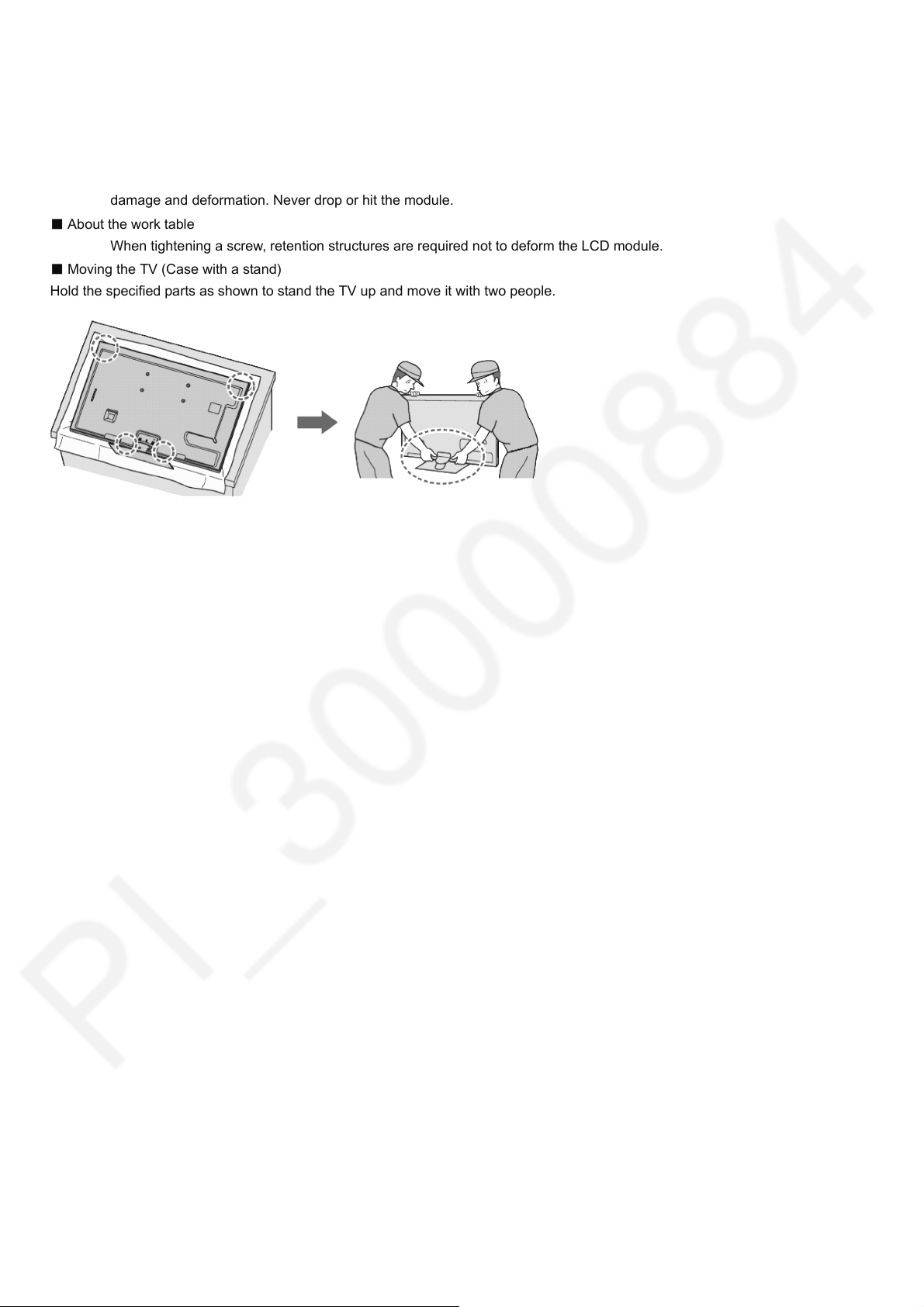
7.17. Handling SPEC
■ Moving the LCD module
The module should be handle by two people and hold on that top and bottom long side by both hands without module
warping. Never handle the module with keeping horizontal position when moving the module in order to avoid internal
damage and deformation. Never drop or hit the module.
■ About the work table
When tightening a screw, retention structures are required not to deform the LCD module.
■ Moving the TV (Case with a stand)
Hold the specified parts as shown to stand the TV up and move it with two people.
30
Page 31

8 Measurements and Adjustments
8.1. Voltage chart of A-board
Set A-Board to a dummy set and check the satisfaction with the specified voltage as following table.
Power Supply Name Measurement Point Specification
PANEL12V TP4097 11.3V - 13V
SUB3.3V TP5400 3.16V - 3.48V
SUB5V TP5420 4.98V - 5.25V
SUB1.5V TP8101 1.45V - 1.57V
SUB1.1V TP8100 1.14V - 1.26V
STB5V TP5200 4.9V - 5.4V
STB3.3V TP5002 3.14V - 3.46V
HDMI3.3V TP8000 3.14V - 3.46V
8.2. Voltage chart of P-board
Set P-Board to a dummy load and check the satisfaction with the specified voltage as following table.
TH-43/49CS630X
Output Test Point
40V TP7407 <1V 40 ± 3.5V
16V TP7410 <1V 15.7 ± 0.6V
5VS TP7501 5.2 ± 0.2V 5.2 ± 0.2V
PFC TP7201 or TP7202 <340V 390V ± 15V *HOT
Step 1 Supply AC 110V/230V to JK7101 connector in the P-Board. Main power button is OFF.
Step 2 Supply DC 2.5V to TV_SUB_ON P2 connector - pin 9 (TNPA6070: TP7416), displayed
as SWITCH.
NOTE : TNPA6070BA,BB,BE > AC supply is 110V
TNPA6070EA,ED,DH,EE,EF,DJ,EP,EQ,DP > AC supply is 230V
Step 1 Step 2
Specification
31
Page 32

TH-43/49CS630X
Panel
S3.3
NAND
FlFlash
1G
XNFCE,XFCE,XNFW
P
NFCLE,NFALE
XNFWE,XFWE,XNFR
E
NANDNANDRYBY
NFD[7:0]
DMD
P-IIC2IIC2 (FoFor DMD ononly)
ADC
DTV Decododer
SIF Decododer
IPR INSINS
Analogog Video
Processssor
Video
Format
Procecessssor
VIF Decododer
I2S
SW
AMP
PWM
SP
DIF
SW
A-Chip
CLK
GEN
A-D Chip
Internalal BUBUS
IIC
DMD-IIC0IIC0
DMD-IIC1IIC1
Trans Port Dececoder
CPUBUUBUS
NAND-IF
PeakPeaks
sLD8sLD8A
STB3.3
IIIIC
STM-M-IIC
Sererial
STM-SM-Serial0
STM-SM-Serial1
2525MHz
STM
USB
S5
USB
Power SW
USB2VBUBUS >
< USB2OC
S5
S5
USB Memory
UU SSBB--IIFF
33ppoorrtt
< KEY1
POWER KEY
CONTROL PANEL KEY
Cross StStreaeam Switch
D-Chip
IIIIC
P-IIC0
P-IIC1
Seririal
P-S-Serial0
P-S-Serial1
P-UAUART0
P-UAUART2
DMD IIIIC
DMD_IIC0
DMD_IIC1
DSP
HDMI
Rx
MUX
x3
LLVVDDSS--TTxx
mmiinnii--LLVV DDSS--TTxx
DD DDRR--IIFF
S1.5
DDDDR3+(1333)
x16
Tcon
Backack LighLight
INVERTER
or
LED Driver
BL_ON >
BL_SOS <
S12
Peakaks
DCDC
VM
S1.1
S1.5
S3.3
STB3.B3.3
STB_XRST
< TV_SOS
AMP/HP MUTE
MONINITOROUT MUTE
S1212/S5STB5B5/5/5VS
Analolog
ASIC
ANAN34043A
OVP
SOS
Safety
CiCircuit
< MON_MUTE
< SP_HP_MUTE
STB3.3V/1.2.2V_RE G
STB5V Reset I IC (STM)
S9V_REG
S12V Reset IC (Peaks)
Audio MUTE
OCP/OVP/TV-SOS
HP_MU_MUTE,EXT_MU_MUTE
UHUHS-I_REG
TV_SOS
PWM
3.3/1.8
UHUHS-1
REG
33 33// 11 88
S9-REG
S9
(SD-Data-VCC)
< (SDVOLC)
DCDCDCDC_EN
DTV_XRST >
SW_OFF_DET >
XRST
POWER_DET
PWM >
PWMA
PWM >
< KEY3
LVDS
FHD: (DATA 4pairs / CLK 1pair) dudual8bitit
DDRDDR3
AIO
VIO
V-SW
A-SW
LAN
EETTHHEERR
PPHHYY
SSDD--IIFF
JTAG
DDR3+(1333)
x16
S1.5
AFB
S12
S33 3
DCDC
DTT
SWW
Peakaks
DCDC
SOUND_VCC
AMPMP
LIN1, RIN1RIN1
Opticalical OUT
OPT
DDC* > STM, Peaksaks
HPD* < STM
HDMI_5HDMI_5V_DET* > STM
HDMI1
DDC* > STM, Peaksaks
HPD* < STM
HDMI_5HDMI_5V_DET* > STM
HDMI2
Rx*Rx*
DDC* > ST
M, Peaksaks
HPD* < STM
HDMI_5HDMI_5V_DET* > STM
HDMI3
Rx*Rx*
Rx*Rx*
IECOUT
Y1,1,P b1,1,Pr1
HS1BC1BCLKIN
HS1SYNCINCIN
HS1VALIN
HS1DIN01DIN0
HS1DIN11DIN1
HS1DIN21DIN2
HS1DIN31DIN3
HS1DIN41DIN4
HS1DIN51DIN5
HS1DIN61DIN6
HS1DIN71DIN7
HS1DIN81DIN8
TS-IN
S3.3 / TU1.8
Terresestrialial(1)
or
Teresestllial/callial/cablele(2)
IF_AGC1
1s1stLow_I_IF IFAGC
Terrrresestrial
DMD_IIC0D_IIC0
LoLow-IF2
< FE_XRST
Demod.
DCDC
1.2V
S3.3
cacable
IF_AGC2
LoLow-IF1
2ndLondLow_I_IF,I,IFAGC
CXD2840D2840/ 2837
< FE_XRST
DMD_IIC1D_IIC1 (IIC2)IC2)
S3.3
ALRCKO
ASDOUT0
ABCKBCKO
ASMCK
ARCOUT
USB
S5
USB
Power SW
USB1VBUS >
< USB1OC
S5
S5
● ●
Louout2,2,Rout2
USB1DB1DP/N/N
USB2DB2DP/N/N
S5
USB
Power SW
USB0VBUS >
< USB0OD
S5
S5
USB0DB0DP/N/N
WiFiWiFi Modulodule
PANEL_TESEST_ON
SCL0/SDA0
Panel
S3.3
NAND
Flash
1G
XNFCE,XNFW
P
NFCLE,NFAL E
XNFWE,XNFR
E
NANDRYBY
NFD[7:0]
DMD
P-IIC2 (For DMD only)
ADC
DTV Decoder
SIF Decoder
IPR INS
Analog V ideo
Processor
Video
Format
Processor
VIF Decoder
I2S
SW
AMP
PWM
SPDIF
SW
A-Chip
CLK
GEN
A-D Chip
Internal BUS
IIC
DMD-IIC0
DMD-IIC1
Trans Port Decoder
CPUBUS
NAND-IF
Peaks
sLD8A
STB3.3
IIC
STM-IIC
Serial
STM-Serial0
STM-Serial1
25MHz
STM
USB
S5
USB
Power SW
USB2VBUS >
< USB2OC
S5
S5
USB Memor y
USB-IF
3port
< KEY1
POWER KEY
CONTROL PANEL KEY
Cross Stream Switch
D-Chip
IIC
P-IIC0
P-IIC1
Serial
P-Serial 0
P-Serial 1
P-UART0
P-UART2
DMD IIC
DMD_IIC0
DMD_IIC1
DSP
HDMI
Rx
MUX
x3
LVDS-Tx
mini-LVDS-Tx
DDR-IF
S1.5
DDR3+(1333)
x16
Tcon
Back Light
INVERTER
or
LED Driver
BL_ON >
BL_SOS <
S12
Peaks
DCDC
VM
S1.1
S1.5
S3.3
STB3.3
STB_XRST
< TV_SOS
AMP/HP M UTE
MONITOROUT MUTE
S12/S5STB5/5VS
Analog
AS IC
AN34043A
OVP
SOS
Safety
Circuit
< MON_MUTE
< SP_HP_MUTE
STB3.3V/1.2V_REG
STB5V Reset IC (STM)
S9V_REG
S12V Reset IC (Peaks)
Audio MUTE
OCP/OVP/TV-SOS
HP_MUTE,EXT_MUTE
UHS-I_REG
TV_SOS
PWM
3.3/1.8
UHS-1
REG
33 33// 11 88
S9-REG
S9
(SD-Data-VCC)
< (SDVOLC)
DCDC_EN
DTV_XRST >
SW_OFF_DET >
XRST
POWER_DET
PWM >
PWMA
PWM >
< KEY3
LVDS
FHD: (DATA 4pairs / CLK 1pair) dual8bit
DDR3
AIO
VIO
V-SW
A-SW
LAN
ETHER
PHY
SD-IF
JTAG
DDR3+(1333)
x16
S1.5
AFB
S12
S333
DCDC
DTT
SWW
Peaks
DCDC
SOUND_VCC
AMP
LIN1, RIN1
Optical OUT
OPT
DDC* > STM, Peaks
HPD* < STM
HDMI_5V_DET* > STM
HDMI1
DDC* > STM, Peaks
HPD* < STM
HDMI_5V_DET* > STM
HDMI2
Rx*
DDC* > STM, Peaks
HPD* < STM
HDMI_5V_DET* > STM
HDMI3
Rx*
Rx*
IECOUT
Y1,Pb1,Pr1
HS1BCLKIN
HS1SYNCIN
HS1VALIN
HS1DIN0
HS1DIN1
HS1DIN2
HS1DIN3
HS1DIN4
HS1DIN5
HS1DIN6
HS1DIN7
HS1DIN8
TS-IN
S3.3 / TU1.8
Terrestrial(1)
or
Terestllial/cable(2)
IF_AGC1
1stLow_IF IFAGC
Terrestrial
DMD_IIC0
Low-IF2
< FE_XRST
Demod.
DCDC
1.2V
S3.3
cable
IF_AGC2
Low-IF1
2ndLow_IF,IFAGC
< FE_XRST
DMD_IIC1 (IIC2)
S3.3
ALRCKO
ASDOUT0
ABCKO
ASMCK
ARCOUT
USB
S5
USB
Power SW
USB1VBUS >
< USB1OC
S5
S5
●●
Lout2,Rout2
USB1DP/N
USB2DP/N
S5
USB
Power SW
USB0VBUS >
< USB0OD
S5
S5
USB0DP/N
WiFi Module
PANEL_TEST_ON
SCL0/SDA0
9 Block Diagram
60
Page 33

10 Wiring Connection Diagram
10.1. Wire Dressing (49 Inch Only)
1. Connect all WIRE.
2. Fix all PET TAPE.
TH-43/49CS630X
No Description Qty UOM Remarks
001 PET TAPE 0.82 MT
002 LVDS CABLE 1 PC
003 WIFI USB CABLE 1 PC
33
Page 34

TH-43/49CS630X
34
Page 35

TH-43/49CS630X
35
Page 36

TH-43/49CS630X
36
Page 37

10.2. Wire Dressing (43 Inch Only)
1. Connect all WIRE.
2. Fix all PET TAPE.
TH-43/49CS630X
No Description Qty UOM Remarks
01 PET TAPE 0.71 WT 60mm x 10
02 110mm x 1
03 WIRE(A02-P2) 1 PC
04 WIRE(A12-SPL/SPR) 1 PC
05 WIRE(A10-K10/BT) 1 PC
06 WIFI USB CABLE 1 PC
07 TSCKF0170183 LVDS CABLE 1 PC
37
Page 38

TH-43/49CS630X
11 Schematic Diagram
Model No. : TH-43CS630X TH-49CS630X A-Board - TH-43CS630X (1/36)
38
Page 39

Model No. : TH-43CS630X TH-49CS630X A-Board - TH-43CS630X (2/36)
Page 40

Model No. : TH-43CS630X TH-49CS630X A-Board - TH-43CS630X (3/36)
Page 41

Model No. : TH-43CS630X TH-49CS630X A-Board - TH-43CS630X (4/36)
Page 42

Model No. : TH-43CS630X TH-49CS630X A-Board - TH-43CS630X (5/36)
Page 43

Model No. : TH-43CS630X TH-49CS630X A-Board - TH-43CS630X (6/36)
Page 44

Model No. : TH-43CS630X TH-49CS630X A-Board - TH-43CS630X (7/36)
Page 45

Model No. : TH-43CS630X TH-49CS630X A-Board - TH-43CS630X (8/36)
Page 46

Model No. : TH-43CS630X TH-49CS630X A-Board - TH-43CS630X (9/36)
Page 47

Model No. : TH-43CS630X TH-49CS630X A-Board - TH-43CS630X (10/36)
Page 48

Model No. : TH-43CS630X TH-49CS630X A-Board - TH-43CS630X (11/36)
Page 49

Model No. : TH-43CS630X TH-49CS630X A-Board - TH-43CS630X (12/36)
Page 50

Model No. : TH-43CS630X TH-49CS630X A-Board - TH-43CS630X (13/36)
Page 51

Model No. : TH-43CS630X TH-49CS630X A-Board - TH-43CS630X (14/36)
Page 52

Model No. : TH-43CS630X TH-49CS630X A-Board - TH-43CS630X (15/36)
Page 53

Model No. : TH-43CS630X TH-49CS630X A-Board - TH-43CS630X (16/36)
Page 54

Model No. : TH-43CS630X TH-49CS630X A-Board - TH-43CS630X (17/36)
Page 55

Model No. : TH-43CS630X TH-49CS630X A-Board - TH-43CS630X (18/36)
Page 56

Model No. : TH-43CS630X TH-49CS630X A-Board - TH-49CS630X (19/36)
Page 57

Model No. : TH-43CS630X TH-49CS630X A-Board - TH-49CS630X (20/36)
Page 58

Model No. : TH-43CS630X TH-49CS630X A-Board - TH-49CS630X (21/36)
Page 59

Model No. : TH-43CS630X TH-49CS630X A-Board - TH-49CS630X (22/36)
Page 60

Model No. : TH-43CS630X TH-49CS630X A-Board - TH-49CS630X (23/36)
Page 61

Model No. : TH-43CS630X TH-49CS630X A-Board - TH-49CS630X (24/36)
Page 62

Model No. : TH-43CS630X TH-49CS630X A-Board - TH-49CS630X (25/36)
Page 63

Model No. : TH-43CS630X TH-49CS630X A-Board - TH-49CS630X (26/36)
Page 64

Model No. : TH-43CS630X TH-49CS630X A-Board - TH-49CS630X (27/36)
Page 65

Model No. : TH-43CS630X TH-49CS630X A-Board - TH-49CS630X (28/36)
Page 66

Model No. : TH-43CS630X TH-49CS630X A-Board - TH-49CS630X (29/36)
Page 67

Model No. : TH-43CS630X TH-49CS630X A-Board - TH-49CS630X (30/36)
Page 68

Model No. : TH-43CS630X TH-49CS630X A-Board - TH-49CS630X (31/36)
Page 69

Model No. : TH-43CS630X TH-49CS630X A-Board - TH-49CS630X (32/36)
Page 70

Model No. : TH-43CS630X TH-49CS630X A-Board - TH-49CS630X (33/36)
Page 71

Model No. : TH-43CS630X TH-49CS630X A-Board - TH-49CS630X (34/36)
Page 72

Model No. : TH-43CS630X TH-49CS630X A-Board - TH-49CS630X (35/36)
Page 73

Model No. : TH-43CS630X TH-49CS630X A-Board - TH-49CS630X (36/36)
Page 74

Model No. : TH-43CS630X TH-49CS630X K-Board
Page 75

Model No. : TH-43CS630X TH-49CS630X P-Board (1/3)
Page 76

Model No. : TH-43CS630X TH-49CS630X P-Board (2/3)
Page 77

Model No. : TH-43CS630X TH-49CS630X P-Board (3/3)
Page 78

12 Printed Circuit Board
Model No. : TH-43CS630X TH-49CS630X A-Board (Top Component Side)
TH-43/49CS630X
78
Page 79

Model No. : TH-43CS630X TH-49CS630X A-Board (Bottom Component Side)
Page 80

Model No. : TH-43CS630X TH-49CS630X K-Board
Page 81

Model No. : TH-43CS630X TH-49CS630X P-Board (Top Component Side)
Page 82

Model No. : TH-43CS630X TH-49CS630X P-Board (Bottom Component Side)
Page 83

TH-43/49CS630X
13 Exploded View and Replacement Parts List
Model No. : TH-43CS630X TH-49CS630X Parts Location
83
Page 84

Model No. : TH-43CS630X TH-49CS630X Packing Exploded View 1
Page 85

Model No. : TH-43CS630X TH-49CS630X Packing Exploded View 2
Page 86

Model No. : TH-43CS630X TH-49CS630X Parts List
Change Safety
CAPACITOR
Ref.
No.
C2000 F1G1A105A107 C 1UF, 16V
C2001 F1G1H102A946 C 1000PF, 50V
C2002 F1G1H102A946 C 1000PF, 50V
C2003 F1G1H102A946 C 1000PF, 50V
C2004 F1G1H102A946 C 1000PF, 50V
C2005 F1G1H102A946 C 1000PF, 50V
C2010 F1G1H101A948 C 100PF, 50V
C2014 F1K1V106A010 C 10UF, 25V
C2023 F1G1C104A173 C 0.1UF, 16V
C2801 F1H1H103B047 C 0.01UF, 50V
C2802 F1H1H103B047 C 0.01UF, 50V
C2803 F1H1H103B047 C 0.01UF, 50V
C2804 F1H1C104A178 C 0.1UF, 16V
C2806 F1H1H103B047 C 0.01UF, 50V
C2807 F1J1A106A043 C 10UF, 10V
C2808 F1H1C104A178 C 0.1UF, 16V
C2851 F1J1H104A902 C 0.1UF, 50V
C2852 F1J1H104A902 C 0.1UF, 50V
C3084 F1H0J105A051 C 1.0UF, 16V
C3085 F1H0J105A051 C 1.0UF, 16V
C3086 F1H0J105A051 C 1.0UF, 16V
C3145 F1J1A106A043 C 10UF, 10V
C3147 F1J1A106A043 C 10UF, 10V
C3151 F1H1A1050039 C 1UF, 10V
C3152 F1H1A1050039 C 1UF, 10V
C3171 F1J1A106A043 C 10UF, 10V
C3172 F1J1A106A043 C 10UF, 10V
C3175 F1J1E105A287 C 1UF, 25V
C3176 F1J1A106A043 C 10UF, 10V
C3177 F1J1E105A287 C 1UF, 25V
C4000 F1H1H103B047 C 0.01UF, 50V
C4001 F1H1H103B047 C 0.01UF, 50V
C4002 F1J1C475A225 C 47UF, 16V
C4701 F1H0J105A051 C 1.0UF, 16V
C4900 F1K1V106A010 C 10UF, 25V
C4901 F1K1V106A010 C 10UF, 25V
C4902 F1J1E105A287 C 1UF, 25V
C4903 F1K1V106A010 C 10UF, 25V
C4904 F1J1E105A287 C 1UF, 25V
C4905 F1H1C105A167 C 1UF, 16V
C4906 F1K1V106A010 C 10UF, 25V
C4907 F1J1E105A287 C 1UF, 25V
C4908 F1K1V106A010 C 10UF, 25V
C4909 F1J1E105A287 C 1UF, 25V
C4919 F1J1E224A272 C 0.22UF 25V
C4920 F1J1E224A272 C 0.22UF 25V
C4921 F1H1E104A161 C 0.1UF, 25V
C4922 F1H1E104A161 C 0.1UF, 25V
C4923 F1H1E104A161 C 0.1UF, 25V
C4924 F1H1E104A161 C 0.1UF, 25V
C5000 F1G1A105A107 C 1UF, 16V
C5002 F1G1A105A107 C 1UF, 16V
C5004 F1G1A105A107 C 1UF, 16V
C5006 F1J1E105A287 C 1UF, 25V
C5012 F1G1A105A107 C 1UF, 16V
C5020 F1G1C104A173 C 0.1UF, 16V
C5021 F1G1A105A107 C 1UF, 16V
C5022 F1G1C104A173 C 0.1UF, 16V
C5026 F1H1E105A153 C 1UF, 25V
C5150 F1G1E103A144 C 0.01UF 25V
C5151 F1G1E103A144 C 0.01UF 25V
Part No. Part Name & Description Q'ty Remarks
Page 87

Model No. : TH-43CS630X TH-49CS630X Parts List
Change Safety
Ref.
No.
C5171 F1G1C103A173 C 0.01UF, 16V
C5400 F1K1V106A010 C 10UF, 25V
C5401 F1K1V106A010 C 10UF, 25V
C5402 F1G1C104A173 C 0.1UF, 16V
C5403 F1J0J2260004 C 22UF, 6.3V
C5404 F1J0J2260004 C 22UF, 6.3V
C5407 F1G1E333A144 C 0.033UF, 25V
C5408 F1G1H222A946 C 2200PF, 50V
C5420 F1K1V106A010 C 10UF, 25V
C5421 F1K1V106A010 C 10UF, 25V
C5422 F1G1C104A173 C 0.1UF, 16V
C5423 F1J0J2260004 C 22UF, 6.3V
C5424 F1J0J2260004 C 22UF, 6.3V
C5427 F1G1E333A144 C 0.033UF, 25V
C5428 F1G1H222A946 C 2200PF, 50V
C5500 F1K1V106A010 C 10UF, 25V
C5502 F1G1C104A173 C 0.1UF, 16V
C5503 F1G1C223A173 C 0.022UF, 16V
C5505 F1G1E332A172 C 0.33UF, 25V
C5507 F1K1V106A010 C 10UF, 25V
C5508 F1K1V106A010 C 10UF, 25V
C5509 F1K1V106A010 C 10UF, 25V
C5717 F1J1A106A043 C 10UF, 10V
C5718 F1J1A106A043 C 10UF, 10V
C6704 F1J1A106A043 C 10UF, 10V
C6707 F1G1C104A173 C 0.1UF, 16V
C6708 F1J1A106A043 C 10UF, 10V
C6710 F1G1C104A173 C 0.1UF, 16V
C6720 F1G1H220A834 C 22PF, 50V
C6721 F1G1H220A834 C 22PF, 50V
C6722 F1G1C104A173 C 0.1UF, 16V
C6723 F1G1H220A834 C 22PF, 50V
C6724 F1G1H220A834 C 22PF, 50V
C6736 F1G1H101A948 C 100PF, 50V
C6737 F1G1H101A948 C 100PF, 50V
C6746 F1G1C104A173 C 0.1UF, 16V
C6750 F1G1H331A946 C 330PF, 50V
C6751 F1G1H121A834 C 120PF, 50V
C6752 F1G1H121A834 C 120PF, 50V
C6753 F1G1H5R0A947 C 5PF, 50V
C6754 F1G1H5R0A947 C 5PF, 50V
C6758 F1G1H181A834 C 180PF, 50V
C6759 F1G1H181A834 C 180PF, 50V
C6760 F1G1H102A948 C 1000PF, 50V
C6762 F1G1H102A948 C 1000PF, 50V
C6763 F1G1C104A173 C 0.1UF, 16V
C6764 F1G1C104A173 C 0.1UF, 16V
C6766 F1G1H102A946 C 1000PF, 50V
C6767 F1G1H102A946 C 1000PF, 50V
C6768 F1G1H102A946 C 1000PF, 50V
C6769 F1G1E103A144 C 0.01UF 25V
C6770 F1G1E103A144 C 0.01UF 25V
C6773 F1G1H102A946 C 1000PF, 50V
C6774 F1G1C104A173 C 0.1UF, 16V
C6775 F1G1C104A173 C 0.1UF, 16V
C6777 F1G0J105A070 C 1UF, 16V
C6778 F1G1C104A173 C 0.1UF, 16V
C6788 F1G1H101A948 C 100PF, 50V
C6799 F1H1H181B052 C 470PF, 50V
C7102 F1AAF471A019 C 470PF, 1KV
C7103 F1AAF471A019 C 470PF, 1KV
C7104 F0CAF2240010 CAPACITOR For TH-43CS630X Only
Part No. Part Name & Description Q'ty Remarks
Page 88

Model No. : TH-43CS630X TH-49CS630X Parts List
Change Safety
Ref.
No.
C7105 F0CAF2240010 C 0.22UF, 250V
C7108 F0CAF3340009 C 0.33UF, 250V For TH-49CS630X Only
C7201 F1H1H102B052 C 1000PF, 50V
C7202 F1J1H222A911 C 2200PF, 50V
C7203 F1H1H104B047 C 0.1UF, 50V
C7204 F1J1E474A272 C 0.47UF 25V
C7206 F1J1E475A257 C 4.7UF 25V
C7207 F1A3A471A060 C 470PF, 1KV
C7208 F1J1H104A902 C 0.1UF, 50V
C7209 ECWFD2W105KC C 1.0UF, 240V For TH-43CS630X Only
C7209 ECWFD2W155KC C 1.5UF, 240V For TH-49CS630X Only
C7213 F2A2W6500001 C 65UF, 450V For TH-49CS630X Only
C7214 F1J1H103A900 C 0.01UF, 50V
C7215 F2A2W6500001 C 65UF, 450V
C7216 ECWFD2W155KC C 1.5UF, 240V For TH-49CS630X Only
C7221 F1A3A101A079 C 100PF, 1KV
C7301 F1J1H223A900 C 0.022UF, 50V
C7302 F1J1H104A902 C 0.1UF, 50V
C7303 F1J1H104A902 C 0.1UF, 50V
C7304 F1A3A221A079 C 220PF, 1KV
C7305 F1J1H105A919 C 1UF, 50V
C7306 F1J1H103A900 C 0.01UF, 50V
C7307 F1J1H101A906 C 100PF, 50V
C7309 F1AAF471A019 C 470PF, 1KV
C7310 F2A1E4710124 C 470PF, 50V
C7311 F1J1H102A909 C 1000PF, 50V
C7312 F1H1C474A178 C 0.47UF, 16V
C7313 F1J1H102A909 C 1000PF, 50V
C7314 F1J1H220A906 C 22PF, 50V
C7315 F1A3A101A079 C 100PF, 1KV
C7316 F1A3A471A060 C 470PF, 1KV
C7317 ECWH8223HAC C 0.022UF, Z, 800V
C7320 F1A3A101A079 C 100PF, 1KV
C7324 F2A1V470B660 C 47PF, 35V
C7418 F1H1H104B047 C 0.1UF, 50V
C7422 F2A1J1210012 C 120PF, 500V
C7423 F2AZZ2220001 CAPACITOR
C7426 F1J1H103A900 C 0.01UF, 50V
C7430 F2A1J1210012 C 120PF, 500V
C7431 F1J1H104A902 C 0.1UF, 50V
C7432 F1J1C475A225 C 47UF, 16V
C7433 F1J1C475A225 C 47UF, 16V
C7434 F1J1C475A225 C 47UF, 16V
C7436 F1H1H104B047 C 0.1UF, 50V
C7438 F1J1C474A238 C 0.47UF, 16V
C7446 F1J1H105A919 C 1UF, 50V
C7551 F1K1E106A167 C 10UF, 25V
C7552 F1K1E106A167 C 10UF, 25V
C7554 F1J1H221A906 C 220PF, 50V
C7555 F1K1E106A167 C 10UF, 25V
C7556 F1K1E106A167 C 10UF, 25V
C7560 F1J1H104A902 C 0.1UF, 50V
C7562 F1J1H104A902 C 0.1UF, 50V
C7563 F1J1H104A902 C 0.1UF, 50V
C7801 F1H1C224A178 C 0.22UF, 16V
C7802 F1H1E104A161 C 0.1UF, 25V
C7803 F1H1H103B047 C 0.01UF, 50V
C7804 F1H1H103B047 C 0.01UF, 50V
C7805 F1J1E105A287 C 1UF, 25V
C7806 F1H1C474A178 C 0.47UF, 16V
C7807 F1H1H102B048 C 1000PF, 50V
C7809 F1A3A102A079 C 1000PF, 1KV
Part No. Part Name & Description Q'ty Remarks
Page 89

Model No. : TH-43CS630X TH-49CS630X Parts List
Change Safety
Ref.
No.
C7810 F1A3A102A079 C 1000PF, 1KV
C7811 F1J2E103A035 C 0.01UF, 250V
C7812 F1J2E103A035 C 0.01UF, 250V
C7813 F1J2E103A035 C 0.01UF, 250V
C7814 F1J2E103A035 C 0.01UF, 250V
C7815 F1J2E103A035 C 0.01UF, 250V
C7817 F1J2E103A035 C 0.01UF, 250V
C7818 F1J2E103A035 C 0.01UF, 250V
C7819 F1J2E103A035 C 0.01UF, 250V
C7823 F2A2C470A222 C 47UF, 160V
C7824 F2A2C470A222 C 47UF, 160V
C7825 F1H1H103B047 C 0.01UF, 50V
C7826 F1J2E103A035 C 0.01UF, 250V
C7827 F1J2E103A035 C 0.01UF, 250V
C7828 F1K1E105A167 C 1UF, 25V
C7829 F1J1H102A909 C 1000PF, 50V
C7830 F1H1H103B047 C 0.01UF, 50V
C7831 F1K1E105A167 C 1UF, 25V
C7832 F1H1H102B048 C 1000PF, 50V
C7839 F2A1J1210012 C 120PF, 500V
C8001 F1G1C104A173 C 0.1UF, 16V
C8002 F1J1A106A043 C 10UF, 10V
C8006 F1G1C104A173 C 0.1UF, 16V
C8010 F1G1C104A173 C 0.1UF, 16V
C8012 F1G1C104A173 C 0.1UF, 16V
C8013 F1G1C104A173 C 0.1UF, 16V
C8014 F1G1A105A107 C 1UF, 16V
C8016 F1G1C104A173 C 0.1UF, 16V
C8018 F1G1A105A107 C 1UF, 16V
C8027 F1G1C104A173 C 0.1UF, 16V
C8028 F1G1C104A173 C 0.1UF, 16V
C8031 F1J1A106A043 C 10UF, 10V
C8032 F1G1C104A173 C 0.1UF, 16V
C8034 F1J1A106A043 C 10UF, 10V
C8037 F1J1A106A043 C 10UF, 10V
C8039 F1G1C104A173 C 0.1UF, 16V
C8042 F1G1C104A173 C 0.1UF, 16V
C8044 F1G1C104A173 C 0.1UF, 16V
C8045 F1G1A105A107 C 1UF, 16V
C8052 F1J0G2260001 C 22UF, 4V
C8054 F1G1C104A173 C 0.1UF, 16V
C8055 F1G1A105A107 C 1UF, 16V
C8057 F1G1C104A173 C 0.1UF, 16V
C8059 F1G1C104A173 C 0.1UF, 16V
C8068 F1G1C104A173 C 0.1UF, 16V
C8071 F1G1C104A173 C 0.1UF, 16V
C8072 F1G1C104A173 C 0.1UF, 16V
C8073 F1G1A105A107 C 1UF, 16V
C8074 F1G1A105A107 C 1UF, 16V
C8076 F1H1A1050039 C 1UF, 10V
C8100 F1G1E472A172 C 0.47UF, 25V
C8101 F1H1E105A153 C 1UF, 25V
C8102 F1G1C104A173 C 0.1UF, 16V
C8103 F1K1V106A010 C 10UF, 25V
C8105 F1J0G2260001 C 22UF, 4V
C8108 F1G1H471A946 C 470PF, 50V
C8109 F1K1V106A010 C 10UF, 25V
C8111 F1G1C104A173 C 0.1UF, 16V
C8112 F1G1C473A173 C 0.047UF, 16V
C8114 F1G1E332A172 C 0.33UF, 25V
C8116 F1J0G2260001 C 22UF, 4V
C8117 F1J0G2260001 C 22UF, 4V
Part No. Part Name & Description Q'ty Remarks
Page 90

Model No. : TH-43CS630X TH-49CS630X Parts List
Change Safety
DIODE
Ref.
No.
C8203 F1G1C104A173 C 0.1UF, 16V
C8204 F1G1C104A173 C 0.1UF, 16V
C8205 F1G1C104A173 C 0.1UF, 16V
C8206 F1G1C104A173 C 0.1UF, 16V
C8207 F1J1A106A043 C 10UF, 10V
C8208 F1G1C104A173 C 0.1UF, 16V
C8210 F1G1C104A173 C 0.1UF, 16V
C8212 F1G1C104A173 C 0.1UF, 16V
C8214 F1G1C104A173 C 0.1UF, 16V
C8216 F1J1A106A043 C 10UF, 10V
C8218 F1G1C104A173 C 0.1UF, 16V
C8220 F1G1C104A173 C 0.1UF, 16V
C8221 F1G1C104A173 C 0.1UF, 16V
C8224 F1G1C104A173 C 0.1UF, 16V
C8229 F1G1A105A107 C 1UF, 16V
C8230 F1G1C104A173 C 0.1UF, 16V
C8231 F1G1C104A173 C 0.1UF, 16V
C8232 F1G1C104A173 C 0.1UF, 16V
C8300 F1G1H100A948 C 10PF, 50V
C8301 F1G1H120A948 C 12PF, 50V
C8307 F1G1A105A107 C 1UF, 16V
C8308 F1G1A105A107 C 1UF, 16V
C8312 F1G1A105A107 C 1UF, 16V
C8313 F1G1A105A107 C 1UF, 16V
C8314 F1G1A105A107 C 1UF, 16V
C8315 F1G1A105A107 C 1UF, 16V
C8452 F1J1A106A043 C 10UF, 10V
C8453 F1G1C104A173 C 0.1UF, 16V
C8455 F1J0J2260004 C 22UF, 6.3V
C8457 F1G1C104A173 C 0.1UF, 16V
C8461 F1J1A106A043 C 10UF, 10V
C8463 F1G1C104A173 C 0.1UF, 16V
C8467 F1J1A106A043 C 10UF, 10V
C8470 F1G1C104A173 C 0.1UF, 16V
C8474 F1J1A106A043 C 10UF, 10V
C8475 F1G1C104A173 C 0.1UF, 16V
C8476 F1J1A106A043 C 10UF, 10V
C8478 F1G1C104A173 C 0.1UF, 16V
C8601 F1G1C103A173 C 0.01UF, 16V
C8602 F1G1C103A173 C 0.01UF, 16V
C8700 F1H1A1050039 C 1UF, 10V
C8850 F1G1E103A144 C 0.01UF 25V
C8900 F1G1C104A173 C 0.1UF, 16V
C8901 F1G1C104A173 C 0.1UF, 16V
C8903 F1G1A105A107 C 1UF, 16V
C8905 F1G1C104A173 C 0.1UF, 16V
D2001 DZ2J047M0L DIODE
D2004 DZ2J047M0L DIODE
D2006 DZ2J047M0L DIODE
D2007 DZ2J047M0L DIODE
D2008 DZ2J056M0L DIODE
D2009 DZ2J047M0L DIODE
D2800 DZ2J056M0L DIODE
D2802 B3AGB0000083 LED
D2851 DZ2J068M0L DIODE
D2852 DZ2J068M0L DIODE
D3101 DZ2J140M0L DIODE
D3102 DZ2J140M0L DIODE
D3103 DZ2J140M0L DIODE
D3104 DZ2J140M0L DIODE
D3105 DZ2J140M0L DIODE
Part No. Part Name & Description Q'ty Remarks
Page 91

Model No. : TH-43CS630X TH-49CS630X Parts List
Change Safety
INTEGRATED CIRCUIT
Ref.
No.
D3106 DZ2J140M0L DIODE
D4704 B0JCED000012 DIODE
D4785 B0JCED000012 DIODE
D5172 DZ2J220M0L DIODE
D5173 DA2J10100L DIODE
D5178 DZ2J068M0L DIODE
D5179 B0ADCK000001 DIODE
D5180 DZ2J033M0L DIODE
D5187 DZ2J047M0L DIODE
D5191 B0ADCK000001 DIODE
D5192 B0ADCK000001 DIODE
D6750 J0ZZB0000175 DIODE
D6752 B0ZBZ0000226 DIODE
D7101 ERZE08C621CD SURGE ABSORBER
D7102 B0FBBR000104 DIODE For TH-49CS630X Only
D7104 B0EAKR000022 DIODE
D7105 B0EAKR000022 DIODE
D7106 B0EBNT000028 DIODE For TH-43CS630X Only
D7211 B0ACCD000008 DIODE
D7217 B0EANR000004 DIODE
D7221 B0ACCD000008 DIODE
D7302 B0HAGQ000001 DIODE
D7304 B0HAGQ000001 DIODE
D7306 B0BC027A0336 DIODE
D7307 B0BC027A0336 DIODE
D7308 B0BC027A0336 DIODE
D7309 B0JCMG000043 DIODE
D7310 B0JCMG000043 DIODE
D7311 B0BC027A0336 DIODE
D7313 B0ACCD000008 DIODE
D7316 ERZE08C621CD SURGE ABSORBER
D7344 DA2JF2300L DIODE
D7345 B0ECKM000053 DIODE
D7401 B0JBSM000009 DIODE
D7404 DA2J10100L DIODE
D7405 DA2J10100L DIODE
D7411 DA2J10100L DIODE
D7413 B0JDSG000009 DIODE
D7414 B0JDSG000009 DIODE
D7550 B0JCPE000051 DIODE
D7552 B0BC6R2A0337 DIODE
D7801 B0JBSM000009 DIODE
D7805 DB2J41100L DIODE
D7808 DA2J10100L DIODE
D7809 DB2J41100L DIODE
D8000 DA2J10100L DIODE
D8850 B0JCED000012 DIODE
IC3052 C0ABBB000483 IC
IC4900 C1AB00003984 IC
IC5000 AN34043AAVF IC
IC5400 C0DBAYY02432 IC
IC5420 C0DBAYY02432 IC
IC5500 C0DBAYY02430 IC
IC5704 C0DBEYY00102 IC
IC6750 C1AB00004172 IC
IC7201 C0DBBYY00089 IC
IC7301 C0DBAYY02411 IC
IC7401 C0DBZYY00545 IC
IC7503 C0DBAYY01915 IC
IC7800 C0ZBZ0002164 IC
IC7801 C0ZBZ0001936 IC
Part No. Part Name & Description Q'ty Remarks
Page 92

Model No. : TH-43CS630X TH-49CS630X Parts List
Change Safety
COIL
TRANSISTOR
Ref.
No.
IC8000 MN2WS0275PBS IC
IC8001 C0DBGYY00887 IC
IC8100 C0DBAYY02431 IC
IC8101 C0DBAYY02430 IC
IC8200 C3ABVY000018 IC
IC8201 C3ABUY000051 IC
IC8453 C0DBZYY00723 IC
IC8454 C0DBZYY00723 IC
IC8457 C0DBZYY00723 IC
IC8900 TVR4G304-AA ROM VERSION ASSEMBLY
IC8901 C3EBGY000056 EEPROM
L2300 J0JYC0000464 BEAD CORE
L3113 J0JYC0000156 INDUCTOR
L3116 J0JYC0000156 INDUCTOR
L4901 G1C220MA0426 INDUCTOR
L4902 G1C220MA0426 INDUCTOR
L4903 G1C220MA0426 INDUCTOR
L4904 G1C220MA0426 INDUCTOR
L5400 G1C4R7ZA0240 INDUCTOR
L5420 G1C6R8MA0426 INDUCTOR
L5500 G1C220MA0445 INDUCTOR
L6704 J0JYC0000464 CHIP BEAD
L6706 J0JYC0000464 CHIP BEAD
L6761 J0JYC0000464 BEAD CORE
L6762 J0JYC0000464 BEAD CORE
L6763 G1CR27JA0097 COIL
L6765 G1C82NJ00010 COIL
L6772 G1CR27JA0097 INDUCTOR
L6773 G1CR27JA0097 INDUCTOR
L6774 G1CR27JA0097 INDUCTOR
L6776 G1CR27JA0097 INDUCTOR
L6777 G1CR22JA0097 CHIP BEAD
L6778 G1CR22JA0097 CHIP BEAD
L7207 J0JYC0000729 COIL
L7209 J0JYA0000035 BEAD CORE
L7302 J0JYB0000044 COIL
L7550 G0C270MA0049 INDUCTOR
L7802 J0JYC0000729 COIL
L7804 G0C470K00027 INDUCTOR For TH-49CS630X Only
L7805 G0C660Z00001 COIL For TH-43CS630X Only
L7806 J0JYB0000044 COIL
L7808 J0JYA0000035 BEAD CORE
L7809 J0JYA0000035 BEAD CORE
L7810 J0JYA0000035 BEAD CORE
L7811 J0JYA0000035 BEAD CORE
L7812 J0JYB0000044 COIL
L7813 J0JYB0000044 COIL
L8001 J0JCC0000287 CHIP BEAD
L8009 J0JYC0000464 CHIP BEAD
L8013 J0JYC0000464 CHIP BEAD
L8014 J0JCC0000287 CHIP BEAD
L8100 G1C2R2ZA0311 INDUCTOR
L8101 G1C3R3MA0464 INDUCTOR
L8460 J0JYC0000464 BEAD CORE
L8461 J0JYC0000464 BEAD CORE
Q2012 B1ABCE000015 TRANSISTOR
Q2013 B1ABCE000015 TRANSISTOR
Q3102 B1ABCE000015 TRANSISTOR
Q3103 B1ABCE000015 TRANSISTOR
Q4702 B1ABCF000231 TRANSISTOR
Part No. Part Name & Description Q'ty Remarks
Page 93

Model No. : TH-43CS630X TH-49CS630X Parts List
Change Safety
RESISTORS
Ref.
No.
Q4709 B1ABCF000231 TRANSISTOR
Q4710 B1ABCF000231 TRANSISTOR
Q4981 B1ABCE000015 TRANSISTOR
Q7201 B1CERR000096 TRANSISTOR
Q7202 B1ADCE000022 TRANSISTOR
Q7204 B1ADGE000012 TRANSISTOR
Q7301 B1CFRR000028 TRANSISTOR
Q7302 B1CFRR000028 TRANSISTOR
Q7303 B1ABCF000231 TRANSISTOR
Q7304 B1ABCF000231 TRANSISTOR
Q7307 B1ABCF000231 TRANSISTOR
Q7401 B1ABCF000231 TRANSISTOR
Q7402 B1CFRG000069 TRANSISTOR
Q7403 B1CHRE000035 TRANSISTOR
Q7404 B1CFRG000069 TRANSISTOR
Q7405 B1CHRE000035 TRANSISTOR
Q7418 B1CBHG000002 TRANSISTOR
Q7419 B1ABCF000231 TRANSISTOR
Q7800 B1ABCF000231 TRANSISTOR
Q7801 B1CERM000047 TRANSISTOR
Q7802 B1ADPG000002 TRANSISTOR
Q7803 B1ADPG000002 TRANSISTOR
Q7804 B1ADPG000002 TRANSISTOR
Q7805 B1ADPG000002 TRANSISTOR
Q7806 B1ADPG000002 TRANSISTOR
Q7807 B1ADPG000002 TRANSISTOR
Q7808 B1ADPG000002 TRANSISTOR
Q7809 B1ADPG000002 TRANSISTOR
Q7814 B1ABCN000007 TRANSISTOR
Q7815 B1ABCF000231 TRANSISTOR
R0904 D0GA473JA023 M 47K Ohm, J, 1/16W
R0905 D0GA101JA023 M 100 Ohm, J, 1/16W
R0906 D0GA101JA023 M 100 Ohm, J, 1/16W
R0907 D0GA101JA023 M 100 Ohm, J, 1/16W
R0908 D0GA101JA023 M 100 Ohm, J, 1/16W
R0909 D0GA101JA023 M 100 Ohm, J, 1/16W
R0910 D0GA332JA023 M 3.3K Ohm, J, 1/16W
R0911 D0GA272JA023 M 2.7K Ohm, J, 1/16W
R0912 D0GA272JA023 M 2.7K Ohm, J, 1/16W
R0913 D0GA332JA023 M 3.3K Ohm, J, 1/16W
R0932 D0GA220JA023 M 22 Ohm, J, 1/16W
R0933 D0GA220JA023 M 22 Ohm, J, 1/16W
R0936 D0GA220JA023 M 22 Ohm, J, 1/16W
R0937 D0GA220JA023 M 22 Ohm, J, 1/16W
R0938 D0GA101JA023 M 100 Ohm, J, 1/16W
R0939 D0GA101JA023 M 100 Ohm, J, 1/16W
R0940 D0GA101JA023 M 100 Ohm, J, 1/16W
R0945 D0GA101JA023 M 100 Ohm, J, 1/16W
R0946 D0GA101JA023 M 100 Ohm, J, 1/16W
R0947 D0GA101JA023 M 100 Ohm, J, 1/16W
R0948 D0GA101JA023 M 100 Ohm, J, 1/16W
R0950 D0GA101JA023 M 100 Ohm, J, 1/16W
R0951 D0GA101JA023 M 100 Ohm, J, 1/16W
R0954 D0GA272JA023 M 2.7K Ohm, J, 1/16W
R0955 D0GA272JA023 M 2.7K Ohm, J, 1/16W
R0956 D0GA332JA023 M 3.3K Ohm, J, 1/16W
R0957 D0GA332JA023 M 3.3K Ohm, J, 1/16W
R0961 D0GA220JA023 M 22 Ohm, J, 1/16W
R0962 D0GA220JA023 M 22 Ohm, J, 1/16W
R1951 D0GA680JA023 M 68 Ohm, J, 1/16W
R1953 D0GA103JA023 M 10K Ohm, J, 1/16W
Part No. Part Name & Description Q'ty Remarks
Page 94

Model No. : TH-43CS630X TH-49CS630X Parts List
Change Safety
Ref.
No.
R2000 D0GA224JA023 M 220K Ohm, J, 1/16W
R2003 D0GAR00J0005 M 0 Ohm, 1/16W
R2008 D0GA473JA023 M 47K Ohm, J, 1/16W
R2013 D0GA101JA023 M 100 Ohm, J, 1/16W
R2014 D0GA101JA023 M 100 Ohm, J, 1/16W
R2016 D0GA302JA023 M 3K Ohm, J, 1/16W
R2017 D0GAR00J0005 M 0 Ohm, 1/16W
R2018 D0GAR00J0005 M 0 Ohm, 1/16W
R2051 D0GA101JA023 M 100 Ohm, J, 1/16W
R2056 D0GAR00J0005 M 0 Ohm, 1/16W
R2058 D0GA473JA023 M 47K Ohm, J, 1/16W
R2059 D0GA103JA023 M 10K Ohm, J, 1/16W
R2060 D0GA473JA023 M 47K Ohm, J, 1/16W
R2061 D0GA223JA023 M 22K Ohm, J, 1/16W
R2062 D0GA101JA023 M 100 Ohm, J, 1/16W
R2067 D0GA101JA023 M 100 Ohm, J, 1/16W
R2806 D0GBR00J0004 M 0 Ohm, J, 1/10W
R2807 D0GBR00J0004 M 0 Ohm, J, 1/10W
R2820 D0GB470JA065 M 47 Ohm, J, 1/10W
R2821 D0GBR00J0004 M 0 Ohm, J, 1/10W
R2823 D1BB4301A073 M 4.3K Ohm, J, 1/10W
R2824 D1BB1001A073 M 1K Ohm, J, 1/10W
R2852 D1BD1911A066 M 1.91K Ohm, F, 1/8W
R2853 D1BD3091A066 M 3.09K Ohm, F, 1/8W
R2854 D1BD6041A066 M 6.04K Ohm, F, 1/8W
R2855 D1BD1692A066 M 16.9K Ohm, F, 1/8W
R3117 D0GA102JA023 M 1K Ohm, J, 1/16W
R3118 D0GA473JA023 M 47K Ohm, J, 1/16W
R3132 D0GB103JA065 M 10K Ohm, J, 1/10W
R3157 D1H82204A042 CHIP RESISTOR
R3163 D0GA104JA023 M 100K Ohm, J, 1/16W
R3164 D0GA104JA023 M 100K Ohm, J, 1/16W
R3167 D0GA333JA023 M 33K Ohm, J, 1/16W
R3168 D0GA333JA023 M 33K Ohm, J, 1/16W
R3171 D0GA332JA023 M 3.3K Ohm, J, 1/16W
R3172 D0GA332JA023 M 3.3K Ohm, J, 1/16W
R3173 D1BB1003A073 M 100K Ohm, J, 1/10W
R3179 D0GA331JA023 M 330 Ohm, J, 1/16W
R3180 D0GA331JA023 M 330 Ohm, J, 1/16W
R3181 D1BD75R0A066 M 75 Ohm, F, 1/8W
R3182 D1BD75R0A066 M 75 Ohm, F, 1/8W
R3183 D1BD75R0A066 M 75 Ohm, F, 1/8W
R3188 D1BB1003A073 M 100K Ohm, J, 1/10W
R3231 D0GB103JA065 M 10K Ohm, J, 1/10W
R3233 D1BB2002A073 M 20K Ohm, J, 1/10W
R3234 D1BB2002A073 M 20K Ohm, J, 1/10W
R3237 D0GB473JA065 M 47K Ohm, J, 1/10W
R3238 D0GB473JA065 M 47K Ohm, J, 1/10W
R4091 D0GA101JA023 M 100 Ohm, J, 1/16W
R4133 D0GAR00J0005 M 0 Ohm, 1/16W
R4138 D0GAR00J0005 M 0 Ohm, 1/16W
R4139 D0GAR00J0005 M 0 Ohm, 1/16W
R4159 D0GAR00J0005 M 0 Ohm, 1/16W
R4715 D0GA103JA023 M 10K Ohm, J, 1/16W
R4721 D0GA103JA023 M 10K Ohm, J, 1/16W
R4722 D0GA103JA023 M 10K Ohm, J, 1/16W
R4723 D0GA473JA023 M 47K Ohm, J, 1/16W
R4724 D0GA102JA023 M 1K Ohm, J, 1/16W
R4725 D0GA473JA023 M 47K Ohm, J, 1/16W
R4731 D0GA103JA023 M 10K Ohm, J, 1/16W
R4739 D0GA220JA023 M 22 Ohm, J, 1/16W
R4748 D0GA680JA023 M 68 Ohm, J, 1/16W
Part No. Part Name & Description Q'ty Remarks
Page 95

Model No. : TH-43CS630X TH-49CS630X Parts List
Change Safety
Ref.
No.
R4749 D0GA680JA023 M 68 Ohm, J, 1/16W
R4750 D0GA680JA023 M 68 Ohm, J, 1/16W
R4751 D0GA680JA023 M 68 Ohm, J, 1/16W
R4752 D1BA1600A023 M 160 Ohm, F, 1/16W
R4753 D1BA82R0A023 M 82 Ohm, F, 1/16W
R4764 D0GA473JA023 M 47K Ohm, J, 1/16W
R4766 D0GA473JA023 M 47K Ohm, J, 1/16W
R4788 D0GA103JA023 M 10K Ohm, J, 1/16W
R4794 D0GA103JA023 M 10K Ohm, J, 1/16W
R4795 D0GA103JA023 M 10K Ohm, J, 1/16W
R4796 D0GA473JA023 M 47K Ohm, J, 1/16W
R4797 D0GA102JA023 M 1K Ohm, J, 1/16W
R4798 D0GA473JA023 M 47K Ohm, J, 1/16W
R4799 D0GA273JA023 M 27K Ohm, J, 1/16W
R4800 D0GA680JA023 M 68 Ohm, J, 1/16W
R4801 D0GA680JA023 M 68 Ohm, J, 1/16W
R4803 D0GA473JA023 M 47K Ohm, J, 1/16W
R4804 D0GA103JA023 M 10K Ohm, J, 1/16W
R4805 D0GA103JA023 M 10K Ohm, J, 1/16W
R4806 D0GA103JA023 M 10K Ohm, J, 1/16W
R4807 D0GA473JA023 M 47K Ohm, J, 1/16W
R4808 D0GA102JA023 M 1K Ohm, J, 1/16W
R4809 D0GA473JA023 M 47K Ohm, J, 1/16W
R4900 D0GFR00J0005 M 0 Ohm, J, 1/3W
R4906 D0GA103JA023 M 10K Ohm, J, 1/16W
R4907 D0GA102JA023 M 1K Ohm, J, 1/16W
R4908 D0GA102JA023 M 1K Ohm, J, 1/16W
R4917 D0GAR00J0005 M 0 Ohm, 1/16W
R4918 D0GAR00J0005 M 0 Ohm, 1/16W
R4919 D0GAR00J0005 M 0 Ohm, 1/16W
R4955 D0GA103JA023 M 10K Ohm, J, 1/16W
R4956 D0GA102JA023 M 1K Ohm, J, 1/16W
R4958 D0GA103JA023 M 10K Ohm, J, 1/16W
R4980 D0GB332JA065 M 3.3K Ohm, J, 1/10W
R4981 D0GA103JA023 M 10K Ohm, J, 1/16W
R4982 D0GA473JA023 M 47K Ohm, J, 1/16W
R4984 D0GA680JA023 M 68 Ohm, J, 1/16W
R4985 D0GA680JA023 M 68 Ohm, J, 1/16W
R4986 D0GA680JA023 M 68 Ohm, J, 1/16W
R4987 D0GA680JA023 M 68 Ohm, J, 1/16W
R5002 D0GA683JA023 M 68K Ohm, J, 1/16W
R5003 D0GA103JA023 M 10K Ohm, J, 1/16W
R5006 D0GA103JA023 M 10K Ohm, J, 1/16W
R5007 D0GA103JA023 M 10K Ohm, J, 1/16W
R5009 D1BA5602A023 M 56K Ohm, F, 1/16W
R5012 D1BA2202A023 M 20K Ohm, F, 1/16W
R5030 D0GA103JA023 M 10K Ohm, J, 1/16W
R5031 D0GAR00J0005 M 0 Ohm, 1/16W
R5032 D0GAR00J0005 M 0 Ohm, 1/16W
R5100 D0GA101JA023 M 100 Ohm, J, 1/16W
R5101 D0GA473JA023 M 47K Ohm, J, 1/16W
R5102 D0GA473JA023 M 47K Ohm, J, 1/16W
R5104 D0GA103JA023 M 10K Ohm, J, 1/16W
R5152 D0GA222JA023 M 2.2K Ohm, J, 1/16W
R5175 D0GA680JA023 M 68 Ohm, J, 1/16W
R5181 D0GA103JA023 M 10K Ohm, J, 1/16W
R5200 D0GBR00J0004 M 0 Ohm, J, 1/10W
R5401 D1BA2202A023 M 20K Ohm, F, 1/16W
R5402 D1BB9100A073 M 910 Ohm, J, 1/10W
R5403 D1BB2871A073 M 2.87K Ohm, J, 1/10W
R5421 D1BA3302A023 M 33K Ohm, F, 1/16W
R5422 D1BB9100A073 M 910 Ohm, J, 1/10W
Part No. Part Name & Description Q'ty Remarks
Page 96

Model No. : TH-43CS630X TH-49CS630X Parts List
Change Safety
Ref.
No.
R5423 D1BB4871A073 M 4.87K Ohm, J, 1/10W
R5500 D1BA4702A023 M 47K Ohm, F, 1/16W
R5501 D1BA3601A023 M 3.6K Ohm, F, 1/16W
R5502 D1BA5102A023 M 51K Ohm, F, 1/16W
R5507 D0GA473JA023 M 47K Ohm, J, 1/16W
R5731 D1BA1200A023 M 120 Ohm, F, 1/16W
R5732 D1BA56R0A023 M 56 Ohm, F, 1/16W
R6728 D0GAR00J0005 M 0 Ohm, 1/16W
R6729 D0GAR00J0005 M 0 Ohm, 1/16W
R6734 D1BA1002A023 M 10K Ohm, F, 1/16W
R6750 D0GA101JA023 M 100 Ohm, J, 1/16W
R6751 D0GA103JA023 M 10K Ohm, J, 1/16W
R6753 D0GA101JA023 M 100 Ohm, J, 1/16W
R6757 D0GA101JA023 M 100 Ohm, J, 1/16W
R6758 D0GA101JA023 M 100 Ohm, J, 1/16W
R6759 D0GA102JA023 M 1K Ohm, J, 1/16W
R6760 D0GA332JA023 M 3.3K Ohm, J, 1/16W
R7101 D0GF105JA048 M 1M Ohm, J, 1/4W
R7102 D0GF105JA048 M 1M Ohm, J, 1/4W
R7103 D0GF105JA048 M 1M Ohm, J, 1/4W
R7104 D0GD102JA052 M 1K Ohm, J, 1/8W
R7105 D0GD102JA052 M 1K Ohm, J, 1/8W
R7201 ERX1SJR22V M 0.22 Ohm, J, 1/10W
R7202 ERX1SJR22V M 0.22 Ohm, J, 1/10W
R7203 D0GD394JA052 M 390K Ohm, J, 1/8W
R7204 D0GF221JA047 M 220 Ohm, J, 1/3W
R7205 D0GD470JA052 M 47 Ohm, J, 1/8W
R7206 D0GF220JA047 M 22 Ohm, J, 1/3W
R7207 D0GB473JA065 M 47K Ohm, J, 1/10W
R7208 ERX1SJR22V M 0.22 Ohm, J, 1/10W
R7211 D0GD104JA052 M 100K Ohm, J, 1/8W
R7212 D0GB223JA065 M 22K Ohm, J, 1/10W
R7219 D0GB513JA065 M 51K Ohm, J, 1/10W
R7220 D0GB223JA065 M 22K Ohm, J, 1/10W
R7224 D1BD8203A066 M 820K Ohm, F, 1/8W
R7225 D1BF1504A073 M 1.5M Ohm, F, 1/16W
R7226 D1BF1504A073 M 1.5M Ohm, F, 1/16W
R7227 D1BF1504A073 M 1.5M Ohm, F, 1/16W
R7228 D1BF1504A073 M 1.5M Ohm, F, 1/16W
R7229 D1BD2003A066 M 200K Ohm, F, 1/8W
R7230 D1BD4422A066 M 44.2K Ohm, F, 1/8W
R7231 D1BD4303A066 M 430K Ohm, F, 1/8W
R7232 D1BD3603A066 M 360K Ohm, F, 1/8W
R7234 D1BD8203A066 M 820K Ohm, F, 1/8W
R7239 D0GF820JA047 M 82 Ohm, J, 1/4W
R7301 D1BD5602A066 M 56K Ohm, F, 1/8W
R7302 D0GD101JA059 M 100 Ohm, J, 1/8W
R7303 D0GD101JA059 M 100 Ohm, J, 1/8W
R7304 D0AF2R2JA112 C 2.2 Ohm, J, 1/2W
R7305 D0AF101JA112 C 100 Ohm, J, 1/2W
R7306 D0GD222JA052 M 2.2K Ohm, J, 1/8W
R7307 D0GD562JA052 M 5.6K Ohm, J, 1/8W
R7308 D0GD222JA052 M 2.2K Ohm, J, 1/8W
R7310 D1BD3302A066 M 33K Ohm, F, 1/8W
R7311 D0XB106JA018 M 10M Ohm, J, 1/16W
R7312 D1BD1802A066 M 18K Ohm, F, 1/8W
R7315 D0GB222JA065 M 2.2K Ohm, J, 1/10W
R7318 D0GD474JA052 M 470K Ohm, J, 1/8W
R7319 D0GD473JA052 M 47K Ohm, J, 1/8W
R7321 D0GD100JA059 M 10 Ohm, J, 1/8W
R7322 D0GD100JA059 M 10 Ohm, J, 1/8W
R7323 D0GD223JA052 M 22K Ohm, J, 1/8W
Part No. Part Name & Description Q'ty Remarks
Page 97

Model No. : TH-43CS630X TH-49CS630X Parts List
Change Safety
Ref.
No.
R7324 D0GD223JA052 M 22K Ohm, J, 1/8W
R7325 ERX1SJ1R0V M 1.0 Ohm, J, 1/10W
R7328 D0AF391JA112 C 390 Ohm, J, 1/2W
R7340 D0GF225JA048 M 2.2K Ohm, J, 1/4W
R7341 D0GF225JA048 M 2.2K Ohm, J, 1/4W
R7342 D0GF225JA048 M 2.2K Ohm, J, 1/4W
R7351 D0GD682JA052 M 6.8K Ohm, J, 1/8W
R7352 D0GD683JA052 M 68K Ohm, J, 1/8W
R7382 D0GD473JA052 M 47K Ohm, J, 1/8W
R7383 D0GD104JA052 M 100K Ohm, J, 1/8W
R7398 D1BD1601A066 M 1.6K Ohm, F, 1/8W
R7401 D0GD472JA052 M 4.7K Ohm, J, 1/8W
R7402 D0GB103JA065 M 10K Ohm, J, 1/10W
R7403 D0GD102JA052 M 1K Ohm, J, 1/8W
R7404 D0GD104JA052 M 100K Ohm, J, 1/8W
R7405 D0GD222JA052 M 2.2K Ohm, J, 1/8W
R7406 D1BD3301A066 M 3.3K Ohm, F, 1/8W
R7407 D0GB103JA065 M 10K Ohm, J, 1/10W
R7408 D1BD1802A066 M 18K Ohm, F, 1/8W
R7409 D0GD473JA052 M 47K Ohm, J, 1/8W
R7410 D0GD473JA052 M 47K Ohm, J, 1/8W
R7411 D0GD473JA052 M 47K Ohm, J, 1/8W
R7412 D0GD473JA052 M 47K Ohm, J, 1/8W
R7421 D0GDR00J0004 M 0 Ohm, J, 1/8W
R7422 D0GD224JA052 M 220K Ohm, J, 1/8W
R7423 D0GD564JA052 M 560K Ohm, J, 1/8W
R7426 D0GD472JA052 M 4.7K Ohm, J, 1/8W
R7441 D0GDR00J0004 M 0 Ohm, J, 1/8W
R7456 D0GDR00J0004 M 0 Ohm, J, 1/8W
R7475 D0GDR00J0004 M 0 Ohm, J, 1/8W
R7476 D0GD105JA052 M 1M Ohm, J, 1/8W
R7477 D0GD225JA052 M 2.2M Ohm, J, 1/8W
R7478 D0GD224JA052 M 220K Ohm, J, 1/8W
R7479 D0GD684JA052 M 680K Ohm, J, 1/8W
R7510 D0GD153JA052 M 15K Ohm, J, 1/8W
R7511 D0GD153JA052 M 15K Ohm, J, 1/8W
R7551 D0GD100JA052 M 10 Ohm, J, 1/8W
R7554 D1BD7872A066 M 78.7K Ohm, F, 1/8W
R7555 D1BD1432A066 M 14.3K Ohm, F, 1/8W
R7557 D0GD514JA052 M 510K Ohm, J, 1/8W
R7800 D1BD2R40A066 M 2.4 Ohm, F, 1/10W
R7801 D1BD2R40A066 M 2.4 Ohm, F, 1/10W
R7802 D1BD2R40A066 M 2.4 Ohm, F, 1/10W
R7803 D1BD2R40A066 M 2.4 Ohm, F, 1/10W
R7804 D1BD2R40A066 M 2.4 Ohm, F, 1/10W
R7805 D1BD2R40A066 M 2.4 Ohm, F, 1/10W
R7806 D1BD2R40A066 M 2.4 Ohm, F, 1/10W
R7807 D1BD2R40A066 M 2.4 Ohm, F, 1/10W
R7808 D0GB103JA065 M 10K Ohm, J, 1/10W
R7809 D1BB1103A143 M 110K Ohm, J, 1/10W For TH-43CS630X Only
R7809 D1BB1603A073 M 160K Ohm, J, 1/10W For TH-49CS630X Only
R7810 D1BB3302A073 M 33K Ohm, J, 1/10W
R7811 D0GB472JA065 M 4.7K Ohm, J, 1/10W
R7812 D1BB1503A073 M 150K Ohm, J, 1/10W
R7815 D1BD1503A066 M 15K Ohm, F, 1/8W
R7816 D1BD1503A066 M 15K Ohm, F, 1/8W
R7817 D0GB114JA065 M 110K Ohm, J, 1/10W
R7818 D0GB203JA065 M 20K Ohm, J, 1/10W
R7819 D0GD1R0JA052 M 1.0 Ohm, J, 1/8W
R7820 D0GDR00J0004 M 0 Ohm, J, 1/8W
R7821 D0GD470JA059 M 47 Ohm, J, 1/8W
R7822 D0GD100JA059 M 10 Ohm, J, 1/8W
Part No. Part Name & Description Q'ty Remarks
Page 98

Model No. : TH-43CS630X TH-49CS630X Parts List
Change Safety
Ref.
No.
R7825 D0GD470JA059 M 47 Ohm, J, 1/8W
R7826 D0GB105JA065 M 1M Ohm, J, 1/10W
R7827 D0GB474JA065 M 470K Ohm, J, 1/10W
R7828 D0GB473JA065 M 47K Ohm, J, 1/10W
R7829 D0GB473JA065 M 47K Ohm, J, 1/10W
R7830 D0GB473JA065 M 47K Ohm, J, 1/10W
R7831 D0GB473JA065 M 47K Ohm, J, 1/10W
R7832 D0GB473JA065 M 47K Ohm, J, 1/10W
R7833 D0GB473JA065 M 47K Ohm, J, 1/10W
R7834 D0GB473JA065 M 47K Ohm, J, 1/10W
R7835 D0GB473JA065 M 47K Ohm, J, 1/10W
R7836 D0GDR00J0004 M 0 Ohm, J, 1/8W
R7837 D0GDR00J0004 M 0 Ohm, J, 1/8W
R7838 D0GDR00J0004 M 0 Ohm, J, 1/8W
R7839 D0GDR00J0004 M 0 Ohm, J, 1/8W
R7840 D0GDR00J0004 M 0 Ohm, J, 1/8W
R7841 D0GDR00J0004 M 0 Ohm, J, 1/8W
R7842 D0GDR00J0004 M 0 Ohm, J, 1/8W
R7843 D0GDR00J0004 M 0 Ohm, J, 1/8W
R7844 D0GB473JA065 M 47K Ohm, J, 1/10W
R7846 D0GB470JA065 M 47 Ohm, J, 1/10W
R7847 D0GB101JA065 M 100 Ohm, J, 1/10W For TH-43CS630X Only
R7847 D0GB470JA065 M 47 Ohm, J, 1/10W For TH-49CS630X Only
R7853 D1BB4701A073 M 470 Ohm, J, 1/10W For TH-49CS630X Only
R7853 D1BB5101A073 M 5.1K Ohm, J, 1/10W For TH-43CS630X Only
R7857 ERX1SJR22V M 0.22 Ohm, J, 1/10W
R7858 ERX1SJR22V M 0.22 Ohm, J, 1/10W
R7860 D1BB1502A073 M 15K Ohm, J, 1/10W For TH-49CS630X Only
R7860 D1BB7502A073 M 7.5K Ohm, J, 1/10W For TH-43CS630X Only
R7863 D0GBR00J0004 M 0 Ohm, J, 1/10W
R7864 ERG2SJ562V RESISTOR
R7865 D0GD104JA052 M 100K Ohm, J, 1/8W
R7866 D0GD103JA052 M 10K Ohm, J, 1/8W
R7867 D0GD473JA052 M 47K Ohm, J, 1/8W
R7868 D0GD103JA052 M 10K Ohm, J, 1/8W
R7869 D0GD473JA052 M 47K Ohm, J, 1/8W
R7870 D0GD103JA052 M 10K Ohm, J, 1/8W
R7871 D0GBR00J0004 M 0 Ohm, J, 1/10W
R7881 D0GD225JA052 M 2.2M Ohm, J, 1/8W
R7882 D0GD225JA052 M 2.2M Ohm, J, 1/8W
R7883 D0GD225JA052 M 2.2M Ohm, J, 1/8W
R7884 D0GD225JA052 M 2.2M Ohm, J, 1/8W
R7885 D0GD225JA052 M 2.2M Ohm, J, 1/8W
R7886 D0GD225JA052 M 2.2M Ohm, J, 1/8W
R7887 D0GD225JA052 M 2.2M Ohm, J, 1/8W
R7888 D0GD225JA052 M 2.2M Ohm, J, 1/8W
R8005 D0GA1R1JA023 M 1.1 Ohm, J, 1/16W
R8010 D0GA511JA023 M 510 Ohm, J, 1/16W
R8011 D0GA104JA023 M 100K Ohm, J, 1/16W
R8102 D1BA4701A023 M 4.7K Ohm, F, 1/16W
R8103 D1BA2002A023 M 20K Ohm, F, 1/16W
R8104 D1BA1802A023 M 18K Ohm, F, 1/16W
R8200 D1BA2400A023 M 240 Ohm, F, 1/16W
R8203 D1BA2700A023 M 270 Ohm, F, 1/16W
R8204 D1BA2700A023 M 270 Ohm, F, 1/16W
R8205 D1BA2700A023 M 270 Ohm, F, 1/16W
R8206 D1BA2700A023 M 270 Ohm, F, 1/16W
R8207 D1BA2700A023 M 270 Ohm, F, 1/16W
R8208 D1BA2700A023 M 270 Ohm, F, 1/16W
R8217 D0GA221JA023 M 220 Ohm, J, 1/16W
R8218 D0GA221JA023 M 220 Ohm, J, 1/16W
R8219 D1BA2400A023 M 240 Ohm, F, 1/16W
Part No. Part Name & Description Q'ty Remarks
Page 99

Model No. : TH-43CS630X TH-49CS630X Parts List
Change Safety
Ref.
No.
R8220 D1BA2400A023 M 240 Ohm, F, 1/16W
R8221 D0GA103JA023 M 10K Ohm, J, 1/16W
R8230 D1BA2700A023 M 270 Ohm, F, 1/16W
R8231 D1BA2700A023 M 270 Ohm, F, 1/16W
R8232 D1BA2700A023 M 270 Ohm, F, 1/16W
R8233 D1BA2700A023 M 270 Ohm, F, 1/16W
R8234 D0GA330JA023 M 33 Ohm, J, 1/16W
R8236 D0GA330JA023 M 33 Ohm, J, 1/16W
R8240 D1H83304A042 CHIP RESISTOR
R8241 D1H83304A042 CHIP RESISTOR
R8242 D1H83304A042 CHIP RESISTOR
R8243 D1H83304A042 CHIP RESISTOR
R8244 D1H83304A042 CHIP RESISTOR
R8245 D0GA330JA023 M 33 Ohm, J, 1/16W
R8246 D0GA330JA023 M 33 Ohm, J, 1/16W
R8300 D0GA331JA023 M 330 Ohm, J, 1/16W
R8301 D0GA360JA023 M 36 Ohm, J, 1/16W
R8302 D0GA360JA023 M 36 Ohm, J, 1/16W
R8303 D1BA6201A023 M 6.2K Ohm, F, 1/16W
R8305 D1BA2491A023 M 2.49k Ohm, F, 1/16W
R8306 D0GA360JA023 M 36 Ohm, J, 1/16W
R8307 D0GA360JA023 M 36 Ohm, J, 1/16W
R8450 D0GA103JA023 M 10K Ohm, J, 1/16W
R8451 D0GA103JA023 M 10K Ohm, J, 1/16W
R8453 D1BA2872A023 M 28.7K Ohm, F, 1/16W
R8454 D0GA103JA023 M 10K Ohm, J, 1/16W
R8455 D0GA103JA023 M 10K Ohm, J, 1/16W
R8457 D1BA2872A023 M 28.7K Ohm, F, 1/16W
R8458 D1BA1652A023 M 16.5K Ohm, F, 1/16W
R8469 D0GA103JA023 M 10K Ohm, J, 1/16W
R8470 D0GA103JA023 M 10K Ohm, J, 1/16W
R8474 D0GA272JA023 M 2.7K Ohm, J, 1/16W
R8478 D0GAR00J0005 M 0 Ohm, 1/16W
R8479 D0GAR00J0005 M 0 Ohm, 1/16W
R8666 D1HY1038A012 CHIP RESISTOR
R8800 D0GA103JA023 M 10K Ohm, J, 1/16W
R8803 D0GA103JA023 M 10K Ohm, J, 1/16W
R8816 D0GA103JA023 M 10K Ohm, J, 1/16W
R8817 D0GA103JA023 M 10K Ohm, J, 1/16W
R8819 D0GA103JA023 M 10K Ohm, J, 1/16W
R8820 D0GA103JA023 M 10K Ohm, J, 1/16W
R8831 D0GA103JA023 M 10K Ohm, J, 1/16W
R8850 D0GA331JA023 M 330 Ohm, J, 1/16W
R8851 D1BB7151A073 M 7.15K Ohm, J, 1/10W
R8852 D0GA102JA023 M 1K Ohm, J, 1/16W
R8853 D0GA182JA023 M 1.8K Ohm, J, 1/16W
R8858 D0GA103JA023 M 10K Ohm, J, 1/16W
R8870 D0GA103JA023 M 10K Ohm, J, 1/16W
R8878 D0GA103JA023 M 10K Ohm, J, 1/16W
R8884 D0GA103JA023 M 10K Ohm, J, 1/16W
R8885 D0GA103JA023 M 10K Ohm, J, 1/16W
R8903 D0GA472JA023 M 4.7K Ohm, J, 1/16W
R8906 D0GA680JA023 M 68 Ohm, J, 1/16W
R8909 D0GA222JA023 M 2.2K Ohm, J, 1/16W
R8910 D0GA103JA023 M 10K Ohm, J, 1/16W
R8911 D1HY1218A012 CHIP RESISTOR
R8914 D0GA680JA023 M 68 Ohm, J, 1/16W
R8915 D0GA680JA023 M 68 Ohm, J, 1/16W
R8916 D0GA680JA023 M 68 Ohm, J, 1/16W
R8917 D0GA680JA023 M 68 Ohm, J, 1/16W
R8918 D0GA680JA023 M 68 Ohm, J, 1/16W
R8919 D0GA680JA023 M 68 Ohm, J, 1/16W
Part No. Part Name & Description Q'ty Remarks
Page 100

Model No. : TH-43CS630X TH-49CS630X Parts List
Change Safety
TRANSFORMER
OTHERS
Ref.
No.
R8924 D0GA102JA023 M 1K Ohm, J, 1/16W
R8926 D0GA332JA023 M 3.3K Ohm, J, 1/16W
R8967 D0GA473JA023 M 47K Ohm, J, 1/16W
R959 D0GA220JA023 M 22 Ohm, J, 1/16W
R960 D0GA220JA023 M 22 Ohm, J, 1/16W
T7201 G4DYA0000496 TRANSFORMER
T7301 G4DYA0000684 TRANSFORMER
A02 K1KY14BA0484 CONNECTOR
A11 K1KY07BA0483 CONNECTOR
A12 K1KY04BA0387 CONNECTOR
A19 K1MY51BA0526 CONNECTOR
C1958 F1G1E103A144 C 0.01UF 25V
CF7101 D4CAY4R7A096 THERMISTORS RESISTOR For TH-43CS630X Only
CF7102 D4CAY2R20002 TERMISTOR For TH-49CS630X Only
F7101 K5E502YYA213 FUSE
JA1 D0GDR00J0004 M 0 Ohm, J, 1/8W
JA2 D0GDR00J0004 M 0 Ohm, J, 1/8W
JA3 D0GDR00J0004 M 0 Ohm, J, 1/8W
JA4 D0GDR00J0004 M 0 Ohm, J, 1/8W
JA5 D0GDR00J0004 M 0 Ohm, J, 1/8W
JA53 D0GFR00J0005 M 0 Ohm, J, 1/3W
JA56 D0GFR00J0005 M 0 Ohm, J, 1/3W
JA58 D0GFR00J0005 M 0 Ohm, J, 1/3W
JA6 D0GDR00J0004 M 0 Ohm, J, 1/8W
JK3101 K1U511D00002 AV TERMINAL
JK3103 K2HC1YYD0001 AV TERMINAL
JK4700 K1FY119D0029 TERMINAL
JK4701 K1FY119D0029 TERMINAL
JK4702 K1FY119E0069 TERMINAL
JK6753 K1ZZ00001557 TUNER SHIELD
JK7101 K2AAYA000004 AC INLET
JK8450 K1FY104B0092 TERMINAL
JK8451 K1FY104B0092 TERMINAL
JK8452 K1FY105E0025 TERMINAL
JK8600 K2LC1YYA0019 TERMINAL
JS0043 D0GAR00J0005 M 0 Ohm, 1/16W
JS0055 D0GAR00J0005 M 0 Ohm, 1/16W For TH-49CS630X Only
JS0059 D0GAR00J0005 M 0 Ohm, 1/16W For TH-43CS630X Only
K10 K1KY07AA1311 CONNECTOR
LD1 K1KY13BA0386 CONNECTOR
LF7103 G0B183GA0082 LINE FILTER For TH-43CS630X Only
LF7104 G0B183GA0082 LINE FILTER For TH-43CS630X Only
LF7105 G0B350GA0083 LINE FILTER
LF7106 G0B103H00018 LINE FILTER For TH-49CS630X Only
LF7107 G0B103H00018 LINE FILTER For TH-49CS630X Only
P2 K1KY16BA0491 CONNECTOR
PA7406 K5H1022A0031 FUSE
PA7409 ERBRE4R00V FUSE RESISTOR
PC7301 B3PAA0000704 PHOTO COUPLERS
PC7302 B3PAA0000704 PHOTO COUPLERS
PC7303 B3PAA0000704 PHOTO COUPLERS
RM2800 B3RBB0000018 PHOTO DETECTOR
SN2800 B3JB00000223 PHOTO DETECTORS
SW2851 EVQ11G05R SWITCH
SW2852 EVQ11G05R SWITCH
SW2853 EVQ11G05R SWITCH
SW2854 EVQ11G05R SWITCH
SW2855 EVQ11G05R SWITCH
SW2857 EVQ11G05R SWITCH
T7201 G4DYA0000496 TRANSFORMER
Part No. Part Name & Description Q'ty Remarks
 Loading...