

Panasonic TH-42PWD4UY User Manual
Wide Plasma Display
®
PLASMA DISPLAY
+
L
O
V
—
T
U
P
N
I
Y
B
D
N
A
/
T
S
-
R
R
N
E
O
W
R
E
O
P
W
O
P
G
Operating Instructions
Model No.
TH-42PWD4
Before connecting, operating or adjusting this product, please read these instructions completely. Please keep this
manual for future reference.
English
TQBC0266
WARNING
RISK OF ELECTRIC SHOCK
DO NOT OPEN
WARNING: To reduce the risk of electric shock do not remove cover or back. No
user-serviceable parts inside. Refer servicing to qualified service personnel.
The lightning flash with
arrow-head within a triangle
is intended to tell the user
that parts inside the product
are a risk of electric shock to
persons.
WARNING: To prevent damage which may result in fire or shock hazard, do not expose this appliance to
rain or moisture.
Do not place containers with water (flower vase, cups, cosmetics, etc.) above the set.
(including on shelves above, etc.)
WARNING: 1) To prevent electric shock, do not remove cover. No user serviceable parts inside. Refer servicing to
qualified service personnel.
2) Do not remove the grounding pin on the power plug. This apparatus is equipped with a three pin
grounding-type power plug. This plug will only fit a grounding-type power outlet. This is a safety
feature. If you are unable to insert the plug into the outlet, contact an electrician.
Do not defeat the purpose of the grounding plug.
The exclamation point within
a triangle is intended to tell
the user that important
operating and servicing
instructions are in the papers
with the appliance.
2

Important Safety Instructions
1) Read these instructions.
All the safety and operating instructions should be read before the appliance is operated.
2) Keep these instructions.
The safety and operating instructions should be retained for future reference.
3) Heed all warnings.
All warnings on the appliance and in the operating instructions should be adhered to.
4) Follow all instructions.
All operating and use instructions should be followed.
5) Do not use this apparatus near water.
For example, near a bathtub, wash bowl, kitchen sink, or laundry tube, in a wet basement, or near a swimming pool,
and the like.
6) Clean only with dry cloth.
Do not use liquid cleaners or aerosol cleaners. Use a dry cloth for cleaning.
7) Do not block any ventilation openings. Install in accordance with the manufacture’s instructions.
Slots and Openings in the cabinet are provided for ventilation and to ensure reliable operation of the product and to
protect it from overheating. The openings should never be blocked by placing the product on a bed, sofa, rug, or other
similar surface.
8) Do not install near any heat sources such as radiators, heat registers, stoves, or other apparatus (including amplifiers)
that produce heat.
This product should not be placed in a built-in installation such as a bookcase or rack unless proper ventilation is
provided or the manufacturer’s instructions have been adhered to.
9) Do not defeat the safety purpose of the polarized or grounding-type plug. A polarized plug has two blades with one wider
than the other. A grounding type plug has two blades and a third grounding prong. The wide blade or the third prong are
provided for your safety. If the provided plug does not fit into your outlet, consult an electrician for replacement of the
obsolete outlet.
10) Protect the power cord from being walked on or pinched particularly at plugs, convenience receptacles, and the point
where they exit from the apparatus.
11) Only use attachments / accessories specified by the Manufacturer.
12) Use only with the cart, stand, tripod, bracket, or table specified by the manufacturer, or sold with the
apparatus. When a cart is used, use caution when moving the cart / apparatus combination to avoid
injury from tip-over.
Quick stops, excessive force, and uneven surfaces may cause the appliance and cart combination
to overturn.
13) Unplug this apparatus during lightning storms or when unused for long periods of time.
This will prevent damage to the product due to lightning and power-line surges.
14) Refer all servicing to qualified service personnel. Servicing is required when the apparatus has been damaged in any
way, such as power-supply cord or plug is damaged, liquid has been spilled or objects have fallen into the apparatus,
the apparatus has been exposed to rain or moisture, does not operate normally, or has been dropped.
15) To prevent electric shock, ensure the grounding pin on the AC cord power plug is securely connected.
3

Dear Panasonic Customer
Welcome to the Panasonic family of customers. We hope that you will have many years of enjoyment
from your new Plasma Display.
To obtain maximum benefit from your set, please read these Instructions before making any adjustments,
and retain them for future reference.
Retain your purchase receipt also, and note down the model number and serial number of your set in
the space provided on the rear cover of these instructions.
Note:
Do not allow a still picture to be displayed for an extended period, as this can cause a permanent afterimage to remain on the Plasma Display.
Examples of still pictures include logos, video games, computer images, teletext and images displayed in
4:3 mode.
Trademark Credits
VGA is a trademark of International Business Machines Corporation.
•
S-VGA is a registered trademark of the Video Electronics Standard Association.
•
Even if no special notation has been made of company or product trademarks, these trademarks have been fully
respected.
4

Table of Contents
Important Safety Instructions .......................................3
FCC STATEMENT ...........................................................6
Safety Precautions.........................................................7
Accessories ....................................................................9
Accessories Supplied....................................................9
Optional Accessories ....................................................9
Remote Control Batteries............................................10
Basic Controls..............................................................11
Connections .................................................................12
Speakers connection ..................................................13
AV Input Terminals connection...................................13
AV Input connection ....................................................14
Video Out ....................................................................14
COMPONENT/RGB Input connection..................................
PC Input connection....................................................16
SERIAL Terminals connection.....................................17
Power ON/OFF and Input Signal Selection................ 18
AC cord conncection..................................................18
Power ON/OFF ...........................................................18
Select the Input Signal ................................................19
Selecting the ON-Screen Menu Language .................19
On-Screen Menu Display from Remote Control........20
ASPECT Controls.........................................................22
Adjusting PICTURE POS./SIZE ...................................24
15
SOUND Adjustment .....................................................26
MUTE..........................................................................26
SURROUND Controls ..................................................27
PICTURE Adjustments.................................................28
Advanced settings.......................................................29
SET UP for MULTI DISPLAY ........................................30
How to setup MULTI DISPLAY....................................30
How to set the Display location number for each Plasma Display..........
SET UP TIMER ..............................................................32
PRESENT TIME OF DAY Set .....................................32
TIMER Set ..................................................................33
SCREENSAVER (For preventing after-images) .........34
Setup of SCREENSAVER Time..................................35
SIDE BAR ADJUST ....................................................36
SET UP for Input Signals.............................................37
COMPONENT/RGB/ IN SELECT ...............................37
3D Y/C FILTER – For NTSC Video images ................37
COLOR SYSTEM / Panasonic AUTO.........................38
[SYNC] ........................................................................39
[PULL IN RANGE].......................................................39
[CLAMP POSITION] ...................................................39
[H-FREQ. (kHz)/V-FREQ. (Hz)] ..................................39
Troubleshooting...........................................................40
Specifications...............................................................42
31
5
FCC STATEMENT
FCC STATEMENT
This equipment has been tested and found to comply with the limits for a Class A digital device, pursuant to part 15 of
the FCC Rules. These limits are designed to provide reasonable protection against harmful interference when the
equipment is operated in a commercial environment.
This equipment generates, uses, and can radiate radio frequency energy and, if not installed and used in accordance
with the instruction manual, may cause harmful interference to radio communications. Operation of this equipment in
a residential area is likely to cause harmful interference in which case the user will be required to correct the interference
at his own expense.
FCC CAUTION:
Pursuant to 47CFR, Part 15.21 of the FCC rules, any changes or modifications to this monitor not expressly approved
by Matsushita Electric Corporation of America could cause harmful interference and would void the user’s authority to
operate this device.
CANADIAN NOTICE:
This Class A digital apparatus complies with Canadian ICES-003.
FCC CAUTION:
To assure continued compliance and possible undesirable interference, the provided ferrite cores must be
used when connecting this plasma display to video equipment; and maintain at least 40cm spacing to other
peripheral devices. Refer to instructions on pages 16, and 17.
6

Safety Precautions
WARNING
Set up
Do not place the Plasma Display on sloped or unstable surfaces.
The Plasma Display may fall off or tip over.
•
Do not place any objects on top of the Plasma Display.
If water spills onto the Plasma Display or foreign objects get inside it, a short-circuit may occur which could result in
•
fire or electric shock. If any foreign objects get inside the Plasma Display, please consult an Authorized Service
Center.
Do not cover the ventilation holes.
Doing so may cause the Plasma Display to overheat, which can cause fire or damage to the Plasma Display.
•
If using the pedestal (optional accessory), leave a space of 3 15/16” (10 cm) or more at the top, left and right, 2 3/8”
(6 cm) or more at the bottom, and 2 3/4” (7 cm) or more at the rear. If using some other setting-up method, leave
a space of 3 15/16” (10 cm) or more at the top, bottom, left and right, and 3/4” (1.9 cm) or more at the rear.
AC Power Supply Cord
The Plasma Display is designed to operate on 120 V AC, 50/60 Hz.
Securely insert the power cord plug as far as it will go.
If the plug is not fully inserted, heat may be generated which could cause fire. If the plug is damaged or the wall
•
socket plate is loose, they should not be used.
Do not handle the power cord plug with wet hands.
Doing so may cause electric shocks.
•
Do not do anything that might damage the power cable. When disconnecting the power cable, hold the plug, not
the cable.
Do not make any modifications, place heavy objects on, place near hot objects, heat, bend, twist or forcefully pull
•
the power cable. Doing so may cause damages to the power cable which can cause fire or electric shock. If damage
to the cable is suspected, have it repaired at an Authorized Service Center.
If the Plasma Display is not in use for a long period of time, unplug the power cord from the wall outlet.
If problems occur during use
If a problem occurs (such as no picture or no sound), or if smoke or an abnormal odor is detected from the
Plasma Display, unplug the power cord immediately.
Continuous use of the Display under these conditions might cause fire or permanent damage to the unit. Have the
•
Display evaluated at an Authorized Service Center. Services to the Display by any unauthorized personnel are
strongly discouraged due to its high voltage dangerous nature.
If water or foreign objects get inside the Plasma Display, if the Plasma Display is dropped, or if the cabinet
becomes damaged, disconnect the power cord plug immediately.
A short may occur, which could cause fire. Contact an Authorized Service Center for any repairs that need to be
•
made.
7

Safety Precautions
CAUTION
This Plasma Display is for use only with the following optional accessories. Use with any other type of optional
accessories may cause instability which could result in the possibility of injury.
(All of the following accessories are manufactured by Matsushita Electric Industrial Co., Ltd.)
Speakers
•
Pedestal
•
Wall stand
•
Mobile stand
•
Wall-habging bracket (vertical)
•
Wall-hanging bracket (angled)
•
Ceiling unit
•
Wall-hanging bracket for PDP with PC
•
Terminal cover
•
Always be sure to ask a qualified technician to carry out set-up.
...................................................
....................................................
.................................................
..............................................
.................
..................
................................................
.....
...........................................
TY-SP42PWD3W
TY-ST42PT3-K
TY-ST42PW1
TY-ST42PF3
TY-WK42PV1
TY-WK42PR1
TY-CE42PS1
TY-WK42PRE1
TY-UPS200
When using the Plasma Display
Do not bring your hands, face or objects close to the ventilation holes of the Plasma Display.
Top of the Plasma Display is usually very hot due to the high temperature of exhaust air being released through the
•
ventilation holes. Burns or personal injuries can happen if any body parts are brought too close. Placing any object
near the top of the display could also result in heat damages to the object as well as to the Display if its ventilation
holes are blocked.
Be sure to disconnect all cables before moving the Plasma Display.
Moving the Display with its cables attached might damage the cables which, in turn, can cause fire or electric
•
shock.
Disconnect the power plug from the wall outlet as a safety precaution before carrying out any cleaning.
Electric shocks can result if this is not done.
•
Clean the power cable regularly to prevent it from becoming dusty.
Built-up dust on the power cord plug can increase humidity which might damage the insulation and cause fire.
•
Unplug the cord from the wall outlet and clean it with a dry cloth.
Cleaning and maintenance
The front of the display panel has been specially treated. Wipe the panel surface gently using only a cleaning
cloth or a soft, lint-free cloth.
If the surface is particularly dirty, soak a soft, lint-free cloth in a weak detergent solution and then wring the cloth to
•
remove excess liquid. Use this cloth to wipe the surface of the display panel, then wipe it evenly with a dry cloth, of
the same type, until the surface is dry.
Do not scratch or hit the surface of the panel with fingernails or other hard objects. Furthermore, avoid contact with
•
volatile substances such as insect sprays, solvents and thinner, otherwise the quality of the surface may be
adversely affected.
If the cabinet becomes dirty, wipe it with a soft, dry cloth.
If the cabinet is particularly dirty, soak the cloth in a weak detergent solution and then wring the cloth dry. Use this
•
cloth to wipe the cabinet, and then wipe it dry with a dry cloth.
Do not allow any detergent to come into direct contact with the surface of the Plasma Display.
•
If water droplets get inside the unit, operating problems may result.
Avoid contact with volatile substances such as insect sprays, solvents and thinner, otherwise the quality of the
•
cabinet surface may be adversely affected or the coating may peel off. Furthermore, do not leave it for long periods
in contact with articles made from rubber or PVC.
Note:
Do not allow a still picture to be displayed for an extended period, as this can cause a permanent after-image to
remain on the Plasma Display.
Examples of still pictures include logos, video games, computer images, teletext and images displayed in 4:3 mode.
8
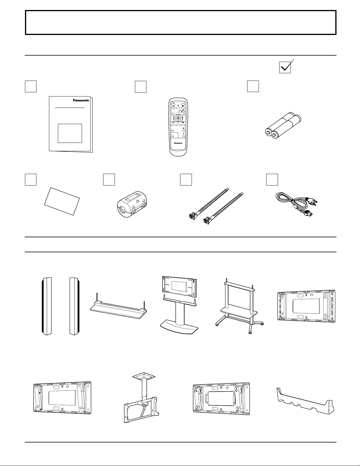
Accessories
Accessories Supplied
Check that you have the Accessories and items shown
Operating Instruction book
Warranty
Ferrite core
J0KF00000018 × 2
Optional Accessories
Remote Control Transmitter
EUR646525
INPUT
SURROUND
VOL
NR
PICTURE
SET UP
SOUND
PICTURE
POS. /SIZE
ASPECT
OFF TIMER
PC
PLASMA DISPLAY
Fixing bands
TMME187 × 2
Batteries for the Remote
Control Transmitter
(AA(R6) Battery × 2)
AC cord
Speakers
•
TY-SP42PWD3W
Wall-hanging bracket
•
(angled)
TY-WK42PR1
Pedestal
•
TY-ST42PT3-K
Ceiling unit
•
TY-CE42PS1
Wall stand
•
TY-ST42PW1
Mobile stand
•
TY-ST42PF3
Wall-hanging bracket
•
for PDP with PC
TY-WK42PRE1
•
For assembling
Full instructions are supplied with each optional accessories for use with this Plasma Display.
Wall-hanging bracket
•
(vertical)
TY-WK42PV1
Terminal cover
TY-UPS200
9
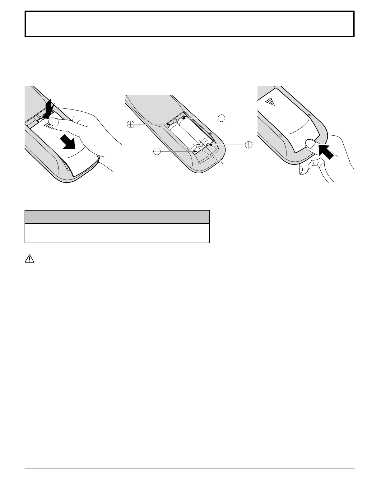
Remote Control Batteries
Requires two AA batteries.
1. Turn the transmitter face down.
Press and slide off the battery
cover.
2. Install the batteries as shown in
the battery compartment.
(Polarity + or – must match the
markings in the compartment).
3. Replace the cove and slide in
reverse until the lock snaps.
Two "AA" size
Helpful Hint:
For frequent remote control users, replace old batteries with
Alkaline batteries for longer life.
Precaution on battery use
Incorrect installation can cause battery leakage and corrosion that will damage the remote control transmitter.
Observe the following precautions:
1. Batteries should always be replaced as a pair. Always use new batteries when replacing the old set.
2. Do not combine a used battery with a new one.
3. Do not mix battery types (example: “Zinc Carbon” with “Alkaline”).
4. Do not attempt to charge, short-circuit, disassemble, heat or burn used batteries.
5. Battery replacement is necessary when the remote control acts sporadically or stops operating the Plasma Display.
10
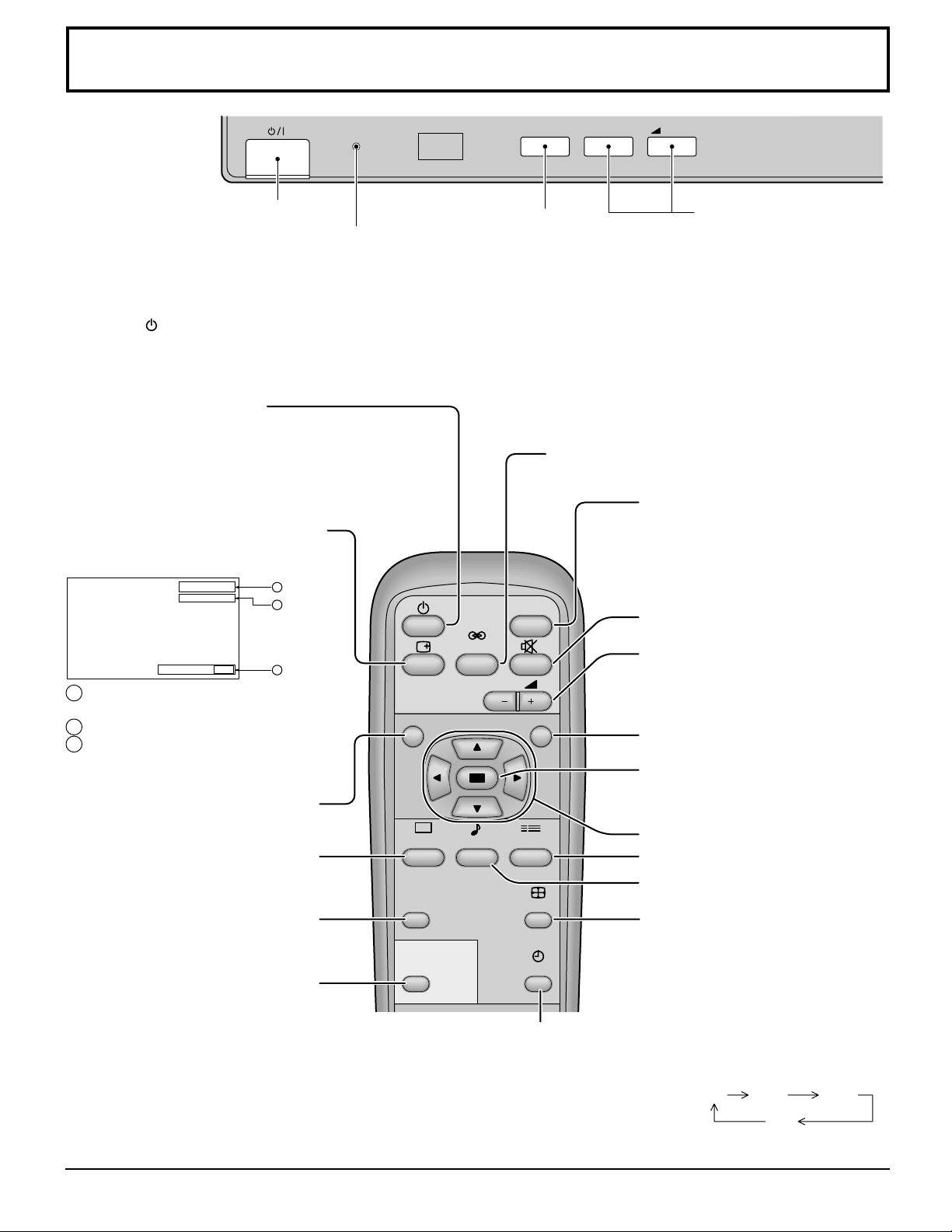
Basic Controls
R - STANDBY
G POWER ON
TY-42PWD4
Main Power On/Off Switch
Power Indicator
The Power Indicator will light.
Power-OFF..... Indicator not illuminated (The unit
•
will still consume some power as long as the
power cord is still inserted into the wall outlet.)
Stand-by ....Red
•
Power-ON......Green
•
(VIDEO (S VIDEO)/COMPONENT,
RGB/PC Mode Selection)
Push the “INPUT” button to select
VIDEO(S VIDEO)/COMPONENT or
RGB/PC input signal modes sequentially.
Stand-by (ON/OFF) button
The Plasma Display must first be plugged into the wall
outlet and turned on at the power switch (see page 18).
Push this button to turn the Plasma Display ON, from
ST ANDBY mode. Push it again to turn the Plasma Display
OFF to ST ANDBY mode.
Status button
Push the “Status” button to display
the current system status.
VIDEO
NORMAL
OFF TIMER 90
1
2
3
1 VIDEO(S VIDEO)/COMPONENT,
RGB/PC mode
2 Aspect mode (see page 22)
NR
3 Off timer
The off timer indicator is displayed
only when the off timer has been set.
N button
(see page 25, 26, 28, 29)
PICTURE
PICTURE button
(see page 28)
PICTURE
POS. /SIZE
PICTURE POS./SIZE button
(see page 24)
PC
PC button
Push the “PC” mode selection
button to select the PC mode.
This button is used to switch
directly to PC mode.
The Plasma Display may be preset to switch to stand-by after a fixed period. The
OFF TIMER button
setting changes to 30 minutes, 60 minutes, 90 minutes and 0 minutes (off timer
cancelled) each time the button is pressed.
When three minutes remain, “Off timer 3” will flash.
The off timer is cancelled if a power interruption occurs.
SURROUND
SOUND
INPUT
Input button
SURROUND button
(see page 27)
INPUT
VOL
SET UP
ASPECT
OFF TIMER
–
VOL
+
V olume Adjustment
Push the Volume Up “+” or
Down “–” button to
increase or decrease the
sound volume level.
Input button
(VIDEO(S VIDEO)/COMPONENT,
RGB/PC Mode Selection)
Press to select VIDEO(S VIDEO)/
COMPONENT or RGB/PC input signal
modes sequentially . (see page 19)
Sound mute On/Off (see page 26)
V olume Adjustment
Press the Volume Up “+” or Down
“–” button to increase or decrease
the sound volume level.
R button (see page 21)
ACTION button
Press to make selections
POSITION buttons
SET UP button (see page 20)
SOUND button (see page 26)
ASPECT button
Press to adjust the aspect.
(see page 22)
30 60
0
90
11
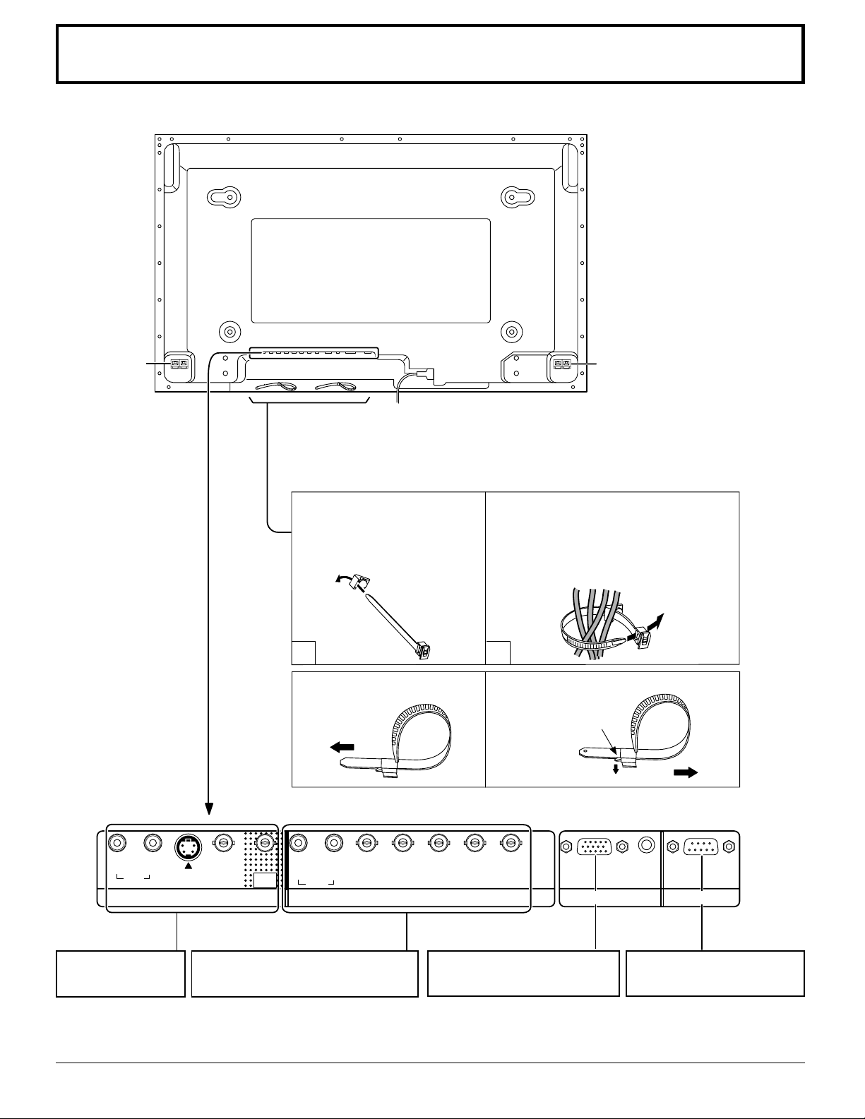
Connections
SPEAKER
Terminals (R)
– Cable fixing bands
Secure any excess cables with bands, as required.
Pass the attached cable fixing
band through the clip as
shown in the figure.
To secure cables connected to
Terminals, wrap the cable fixing band
around them then pass the pointed end
through the locking block, as shown in
the figure.
1
To tighten:
Pull
2
To loosen:
Push
the catch
SPEAKER
Terminals (L)
Pull
RL
AUDIO
IN
AV IN Terminals
(see page 13, 14)
12
S VIDEOINVIDEO
IN
VIDEO
OUT
RL
AUDIO
COMPONENT/RGB IN and Audio
IN Terminals (see page 15)
AUDIO
HD
VD
COMPONENT/RGB INAV
PB/CB/B Y/G
PR/CR/R
PC IN SERIAL
From EXIT monitor Terminal
on Computer (see page 16)
From SERIAL Terminal on
Computer (see page 17)
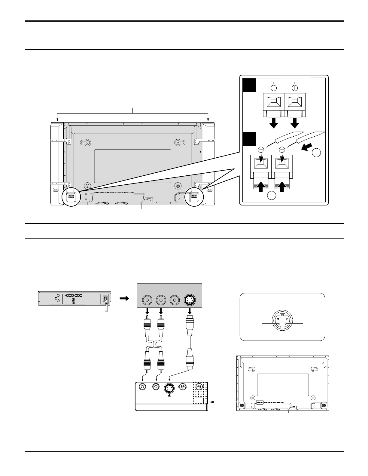
Speakers connection
When connecting the speakers, be sure to use only the optional accessory
speakers.
Refer to the speaker’s Installation Manual for details on speaker installation.
Speakers (Optional accessories)
Connections
1
2
1
AV Input Terminals connection
Connect the signal source equipment (see page 14 to 17).
(Example) When connecting an S VIDEO VCR
(S VIDEO VCR)
2×RCA audio
cables
AUDIO
Audio input to
L/R sockets
Audio
OUT
RL
Video
OUT
S VIDEO
OUT
S VIDEO
Video input to
S VIDEO
socket
2
S VIDEO 4 pin socket
Luminance earth
Luminance in
Chrominance earth
Chrominance in
RL
AUDIO
IN
S VIDEOINVIDEO
AV
VIDEO
OUT
IN
Notes:
(1) Change the “COMPONENT/RGB-IN” setting in the “SET UP” menu to “RGB”. (see page 37, 39)
(2) Additional equipment and cables shown are not supplied with this set.
13
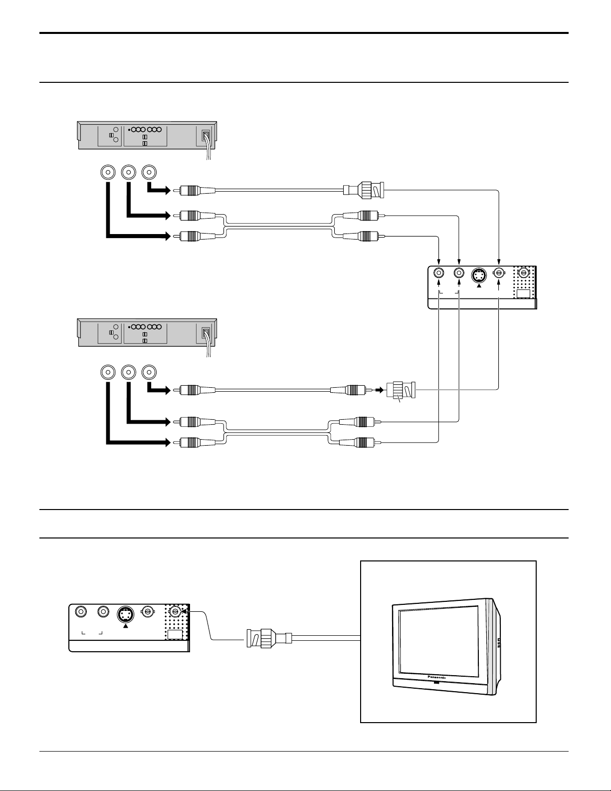
Connections
AV Input connection
VIDEO signal connection
(VCR)
Audio
RL
OUT
Video
OUT
VIDEO
Video input to
BNC socket
RCA video cable
AUDIO
2×RCA audio cables
Audio input to
L/R sockets
RL
AUDIO
IN
(VCR)
Audio
RL
OUT
Video
OUT
VIDEO
Video input to
BNC socket
RCA video cable
RCA-BNC adapter plug
AUDIO
2×RCA audio cables
Audio input to L/R sockets
Notes:
(1) Change the “COMPONENT/RGB-IN” setting in the “SET UP” menu to “RGB”. (see page 37, 39)
(2) Additional equipment and cables shown are not supplied with this set.
S VIDEO
IN
VIDEO
VIDEO
OUT
IN
AV
VIDEO OUT
RL
14
AUDIO
IN
S VIDEO
IN
AV
VIDEO
IN
VIDEO
OUT
MONITOR DEVICE
BNC cable
(Example) color CRT monitor
 Loading...