

Page 1
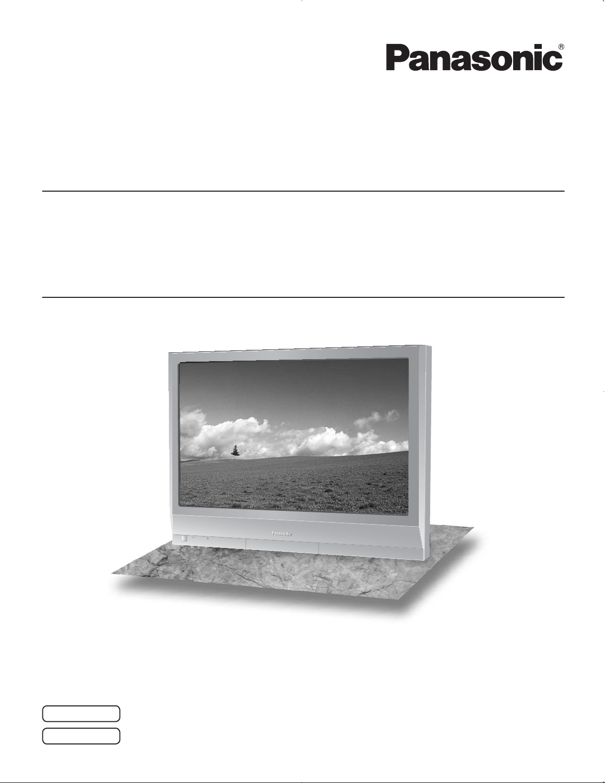
Operating Instructions
Progressive Wide Hospitality Plasma Display
Manual de instrucciones
Pantalla panorámica de plasma progresiva para la industria hotelera
Model No.
Número de modelo.
TH-37PG9U
TH-42PG9U
High Defi nition Hospitality Plasma Display
Pantalla de plasma de alta defi nición para la industria hotelera
Model No.
Número de modelo.
TH-37PR9U
TH-42PR9U
English
Español
The illustration shown is an image.
Before connecting, operating or adjusting this product, please read these instructions completely.
Please keep this manual for future reference.
La ilustración mostrada es una imagen.
Antes de conectar, utilizar o ajustar este producto, lea completamente este manual de instrucciones;
y guárdelo para consultarlo en el futuro en caso de ser necesario.
TQB2AA0701-1
Page 2
CAUTION
RISK OF ELECTRIC SHOCK
DO NOT OPEN
WARNING: To reduce the risk of electric shock, do not remove cover or back.
No user-serviceable parts inside. Refer servicing to qualifi ed service personnel.
The lightning flash with
arrow-head within a triangle
is in tended to tell the user
that parts inside the product
are a risk of electric shock
to per sons.
The exclamation point within
a triangle is intended to
tell the user that important
operating and servicing
instructions are in the papers
with the ap pliance.
WARNING : To prevent damage which may result in fire or shock hazard, do not expose this apparatus to rain
or mois ture.
Do not place containers with water (flower vase, cups, cosmetics, etc.) above the set.
(including on shelves above, etc.)
WARNING : 1) To prevent electric shock, do not remove cover. No user serviceable parts inside. Refer servicing to
qualified service personnel.
2) Do not remove the grounding pin on the power plug. This apparatus is equipped with a three pin
grounding-type power plug. This plug will only fit a grounding-type power outlet. This is a safety fea ture.
If you are unable to insert the plug into the outlet, contact an electrician.
Do not defeat the purpose of the grounding plug.
2
Page 3

Important Safety Instructions
1) Read these instructions.
2) Keep these instructions.
3) Heed all warnings.
4) Follow all instructions.
5) Do not use this apparatus near water.
6) Clean only with dry cloth.
7) Do not block any ventilation openings. Install in accordance with the manufacturer’s instructions.
8) Do not install near any heat sources such as radiators, heat registers, stoves, or other apparatus (including
amplifi ers) that produce heat.
9) Do not defeat the safety purpose of the polarized or grounding-type plug. A polarized plug has two blades with one
wider than the other. A grounding type plug has two blades and a third grounding prong. The wide blade or the
third prong are provided for your safety. If the provided plug does not fi t into your outlet, consult an electrician for
replacement of the obsolete outlet.
10) Protect the power cord from being walked on or pinched particularly at plugs, convenience receptacles, and the
point where they exit from the apparatus.
11) Only use attachments / accessories specifi ed by the manufacturer.
12) Use only with the cart, stand, tripod, bracket, or table specifi ed by the manufacturer, or sold with
the apparatus. When a cart is used, use caution when moving the cart / apparatus combination
to avoid injury from tip-over.
13) Unplug this apparatus during lightning storms or when unused for long periods of time.
14) Refer all servicing to qualifi ed service personnel. Servicing is required when the apparatus has been damaged
in any way, such as power-supply cord or plug is damaged, liquid has been spilled or objects have fallen into the
apparatus, the apparatus has been exposed to rain or moisture, does not operate normally, or has been dropped.
15) To prevent electric shock, ensure the grounding pin on the AC cord power plug is securely connected.
3
Page 4

Dear Panasonic Customer
Welcome to the Panasonic family of customers. We hope that you will have many years of enjoyment
from your new Plasma Display.
To obtain maximum benefit from your set, please read these Instructions before making any adjustments,
and retain them for future reference.
Retain your purchase receipt as well, and record the model number and serial number of your set in the
space provided on the rear cover of these instructions.
Table of Contents
Important Safety Instructions .................................. 3
FCC STATEMENT ...................................................... 5
Safety Precautions ................................................... 6
Maintenance .............................................................. 7
Accessories .............................................................. 8
Accessories Supplied .............................................. 8
Connections .............................................................. 9
PC Input Terminals connection .............................. 10
SERIAL Terminals connection ............................... 11
Power ON / OFF ..................................................... 12
Initial selections ..................................................... 13
Selecting the input signal ...................................... 13
Selecting the On-Screen Menu Language ............ 13
Basic Controls ........................................................ 14
On-Screen Menu Displays ..................................... 16
ASPECT Controls ................................................... 18
Adjusting POS. /SIZE ............................................. 19
MULTI PIP ................................................................ 20
Advanced PIP .......................................................... 21
PICTURE Adjustments ........................................... 22
ADVANCED SETTINGS ........................................ 23
SOUND Adjustment ................................................ 24
MUTE .................................................................... 24
Digital Zoom ............................................................ 25
PRESENT TIME SETUP / SET UP TIMER .............. 26
PRESENT TIME SETUP ....................................... 26
SET UP TIMER ..................................................... 27
SCREENSAVER (For preventing after-images) ... 28
Setup of SCREENSAVER Time ............................ 29
Reduces screen after-image ................................. 29
SIDE BAR ADJUST ............................................... 30
Reduces power consumption ............................... 31
Customizing the Input labels ................................. 31
SET UP for Input Signals ....................................... 32
COMPONENT / RGB IN SELECT ......................... 32
3D Y/C FILTER ...................................................... 32
COLOR SYSTEM / Panasonic AUTO ................... 33
3:2 PULLDOWN / VIDEO NR ................................ 33
SYNC .................................................................... 34
H-FREQ. (kHz) / V-FREQ. (Hz) ............................. 34
Options Adjustments ............................................. 35
Shipping condition ................................................. 38
Troubleshooting ..................................................... 39
PC input signals ..................................................... 40
Specifications ......................................................... 41
4
Page 5
FCC STATEMENT
This equipment has been tested and found to comply with the limits for a Class B digital device, pursuant to Part
15 of the FCC Rules. These limits are designed to provide reasonable protection against harmful interference in a
residential installation. This equipment generates, uses and can radiate radio frequency energy and, if not installed
and used in accordance with the instructions, may cause harmful interference to radio communications. However,
there is no guarantee that interference will not occur in a particular installation. If this equipment does cause harmful
interference to radio or television reception, which can be determined by turning the equipment off and on, the user
is encouraged to try to correct the interference by one or more of the following measures:
• Reorient or relocate the receiving antenna.
• Increase the separation between the equipment and receiver.
• Connect the equipment into an outlet on a circuit different from that to which the receiver is connected.
• Consult the dealer or an experienced technician for help.
This device complies with Part15 of the FCC Rules. Operation is subject to the following two conditions:(1) This
device may not cause harmful interference, and (2) this device must accept any interference received, including
interference that may cause undesired operation.
FCC CAUTION:
Pursuant to 47CFR, Part 15.21 of the FCC rules, any changes or modifi cations to this monitor not expressly
approved by Panasonic Corporation of North America could cause harmful interference and would void the
user’s authority to operate this device.
FCC Declaration of Conformity
Model No. TH-37PG9U, TH-42PG9U, TH-37PR9U, TH-42PR9U
Responsible Party: Panasonic Corporation of North America
One Panasonic Way, Secaucus, NJ 07094
Contact Source: Panasonic Broadcast & Television Systems Company
1-800-524-1448
email: pbtscservice@us.panasonic.com
CANADIAN NOTICE:
This Class B digital apparatus complies with Canadian ICES-003.
Note:
Do not allow a still picture to be displayed for an extended period, as this can cause permanent after-image to
remain on the Plasma Display.
Examples of still pictures include logos, video games, computer images, teletext and images displayed in NORMAL mode.
Trademark Credits
• VGA is a trademark of International Business Machines Corporation.
• Macintosh is a registered trademark of Apple Computer, USA.
• S-VGA is a registered trademark of the Video Electronics Standard Association.
Even if no special notation has been made of company or product trademarks, these trademarks have been fully
respected.
5
Page 6

Safety Precautions
CAUTION
This Plasma Display is for use only with the following optional accessories. Use with any other type of optional
accessories may cause instability which could result in the possibility of injury.
(All of the following accessories are manufactured by Matsushita Electric Industrial Co., Ltd.)
• Pedestal ...................................................................................................................... TY-ST09GR-K
• Wall-hanging bracket (vertical) ................................................................................... TY-WK42PV3U
• Wall-hanging bracket (angled) .................................................................................... TY-WK42PR2U, TY-WK42PR3U
• BNC Component Video Terminal Board ..................................................................... TY-42TM6A
• BNC Composite Video Terminal Board ....................................................................... TY-42TM6B
• BNC Dual Video Terminal Board ................................................................................ TY-FB9BD
• Ir Through Terminal Board .......................................................................................... TY-FB9RT
• RCA Component Video Terminal Board ..................................................................... TY-42TM6Z
• RCA Composite Video Terminal Board ....................................................................... TY-42TM6V
• PC Input Terminal Board ............................................................................................ TY-42TM6P
• RGB (Digital) Terminal Board ..................................................................................... TY-42TM6D
• HDMI Terminal Board ................................................................................................. TY-FB8HM
• U/V Tuner Board with MATE I/F .................................................................................. TY-FB9TU
(except for Canada)
Always be sure to ask a qualified technician to carry out set-up.
Small parts can present choking hazard if accidentally swallowed. Keep small parts away from young children. Discard
unneeded small parts and other objects, including packaging materials and plastic bags/sheets to prevent them from being
played with by young children, creating the potential risk of suffocation.
When using the Plasma Display
Do not bring your hands, face or objects close to the
ventilation holes of the Plasma Display.
• Top of the Plasma Display is usually very hot due to the
high temperature of exhaust air being released through
the ventilation holes. Burns or personal injuries can
happen if any body parts are brought too close. Placing
any object near the top of the display could also result in
heat damages to the object as well as to the Display if its
ventilation holes are blocked.
Be sure to disconnect all cables before moving the
Plasma Display.
• Moving the Display with its cables attached might
damage the cables which, in turn, can cause fire or
electric shock.
Disconnect the power plug from the wall outlet as a
safety precaution before carrying out any cleaning.
• Electric shocks can result if this is not done.
6
Clean the power cable regularly to prevent it from
becoming dusty.
• Built-up dust on the power cord plug can increase
humidity which might damage the insulation and cause
fire. Unplug the cord from the wall outlet and clean it
with a dry cloth.
This Plasma Display radiates infrared rays, therefore it
may affect other infrared communication equipment.
Install your infrared sensor in a place away from direct
or reflected light from your Plasma Display.
Note:
Do not allow a still picture to be displayed for an extended
period, as this can cause a permanent after-image to remain
on the Plasma Display.
Examples of still pictures include logos, video games,
computer images, teletext and images displayed in
NORMAL mode.
Page 7

WARNING
Safety Precautions / Maintenance
Setup
Do not place the Plasma Display on sloped or unstable
surfaces.
• The Plasma Display may fall off or tip over.
Do not place any objects on top of the Plasma
Display.
• If water spills onto the Plasma Display or foreign objects
get inside it, a short-circuit may occur which could
result in fire or electric shock. If any foreign objects get
inside the Plasma Display, please consult an Authorized
Service Center.
Do not cover the ventilation holes.
• Doing so may cause the Plasma Display to overheat,
which can cause fire or damage to the Plasma
Display.
If using the pedestal (optional accessory), leave a space
of 3
15/16” (10 cm) or more at the top, left and right, 2 3/8”
(6 cm) or more at the bottom, and 2
the rear. If using some other setting-up method, leave a
space of 3
and right, and 2
15/16” (10 cm) or more at the top, bottom, left
3/4” (7 cm) or more at the rear.
3/4” (7 cm) or more at
AC Power Supply Cord
The Plasma Display is designed to operate on 120 V
AC, 50/60 Hz.
Securely insert the power cord plug as far as it will
go.
• If the plug is not fully inserted, heat may be generated
which could cause fire. If the plug is damaged or the
wall socket plate is loose, they should not be used.
Do not handle the power cord plug with wet hands.
• Doing so may cause electric shocks.
Do not do anything that might damage the power cable.
When disconnecting the power cable, hold the plug,
not the cable.
• Do not make any modifications, place heavy objects on,
place near hot objects, heat, bend, twist or forcefully
pull the power cable. Doing so may cause damage to
the power cable which can cause fire or electric shock.
If damage to the cable is suspected, have it repaired at
an Authorized Service Center.
If the Plasma Display will not be used for a long period
of time, unplug the power cord from the wall outlet.
If problems occur during use
If a problem occurs (such as no picture or no sound),
or if smoke or an abnormal odor is detected from the
Plasma Display, unplug the power cord immediately.
• Continuous use of the Display under these conditions
might cause fire or permanent damage to the unit.
Have the Display evaluated at an Authorized Service
Center. Services to the Display by any unauthorized
personnel are strongly discouraged due to its high
voltage dangerous nature.
If water or foreign objects get inside the Plasma Display,
if the Plasma Display is dropped, or if the cabinet
becomes damaged, disconnect the power cord plug
immediately.
• A short may occur, which could cause fire. Contact an
Authorized Service Center for any repairs that need to be
made.
Maintenance
The front of the display panel has been specially treated. Wipe the panel surface gently using only a cleaning
cloth or a soft, lint-free cloth.
• If the surface is particularly dirty, wipe with a soft, lint-free cloth which has been soaked in pure water or water to which
a small amount of neutral detergent has been added, and then wipe it evenly with a dry cloth of the same type until the
surface is dry.
• Do not scratch or hit the surface of the panel with fingernails or other hard objects, otherwise the surface may become
damaged. Furthermore, avoid contact with volatile substances such as insect sprays, solvents and thinner, otherwise
the quality of the surface may be adversely affected.
If the cabinet becomes dirty, wipe it with a soft, dry cloth.
• If the cabinet is particularly dirty, soak the cloth in water to which a small amount of neutral detergent has been added
and then wring the cloth dry. Use this cloth to wipe the cabinet, and then wipe it dry with a dry cloth.
• Do not allow any detergent to come into direct contact with the surface of the Plasma Display. If water droplets get
inside the unit, operating problems may result.
• Avoid contact with volatile substances such as insect sprays, solvents and thinner, otherwise the quality of the cabinet
surface may be adversely affected or the coating may peel off. Furthermore, do not leave it for long periods in contact
with articles made from rubber or PVC.
7
Page 8
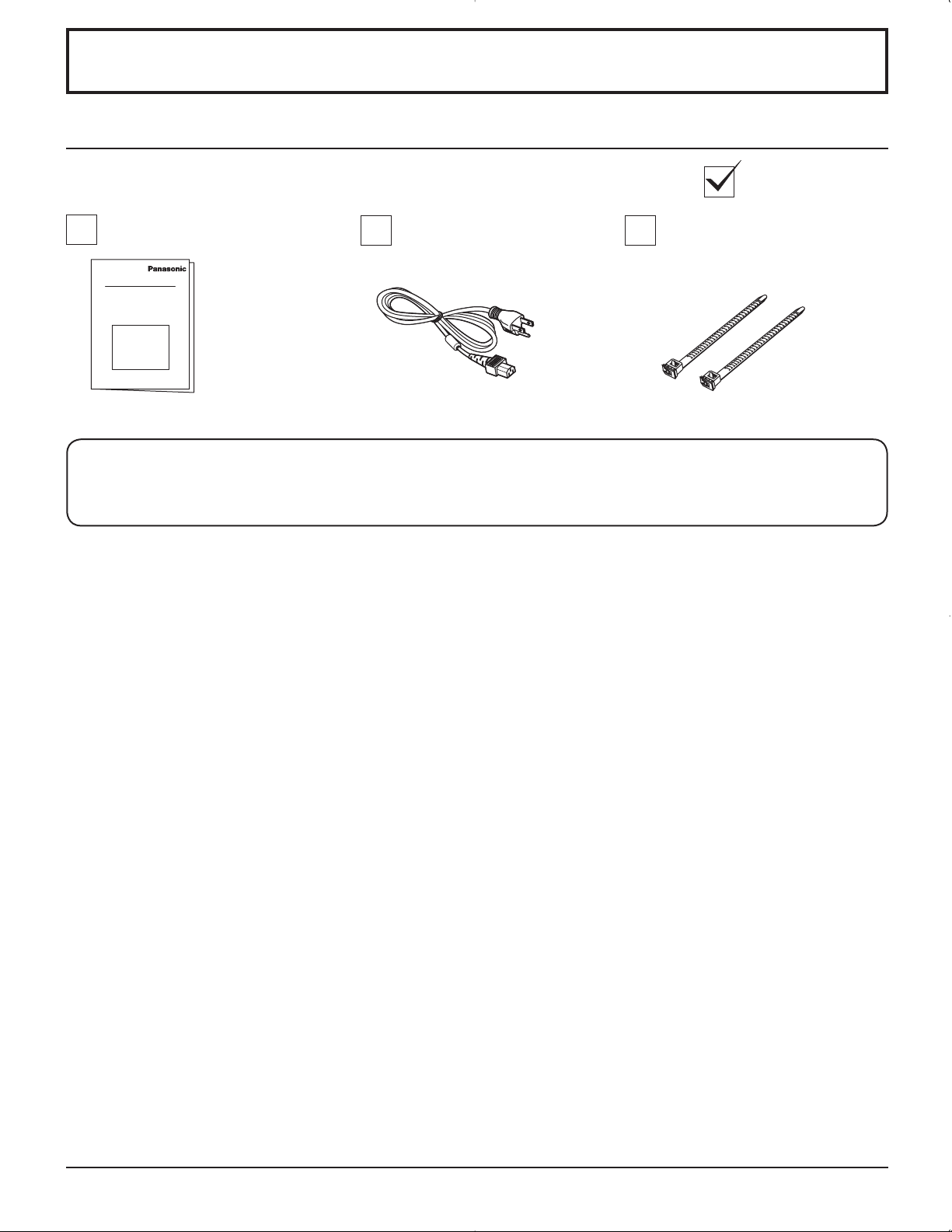
Accessories
Accessories Supplied
Check that you have the Accessories and items shown
Operating Instruction book AC cord
The remote control is not included with this set. Available for purchase separately.
Object model : EUR7636070R
Fixing bands × 2
8
Page 9
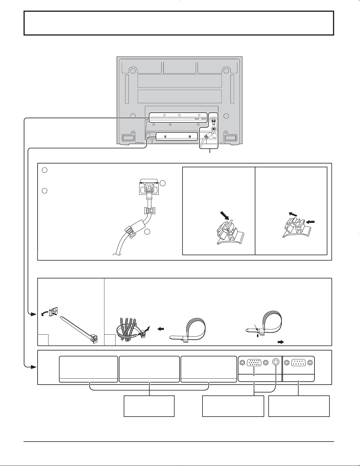
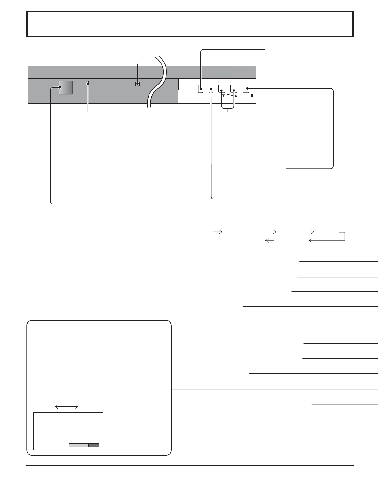
Connections
– AC cord fixing
Connect power plug to
1
the socket of the main
body.
2
Fix the clamper.
2
– Cable fixing bands
Secure any excess cables with bands as required.
Pass the attached cable
fixing band through the
clip as shown in the
figure.
To secure cables connected to Terminals, wrap the cable fixing band around them then
pass the pointed end through the locking block, as shown in the figure.
While ensuring there is sufficient slack in cables to minimize stress (especially
in the power cord), firmly bind all cables with the supplied fixing band.
1
To tighten:
Pull
AC cord connection (see page 12)
How to fix:
Fix by pushing in until a
clicking sound is heard.
To loosen:
Push the catch
How to release:
Pull up while drawing in
the knob.
1
SLOT1 SLOT2 SLOT3
2
Optional Terminal
Board Insert Slot
(covered)
From EXTERNAL
monitor terminal on
Computer (see page 10)
Pull
AUDIO
SERIALPC IN
From SERIAL
Terminal on Computer
(see page 11)
9
Page 10
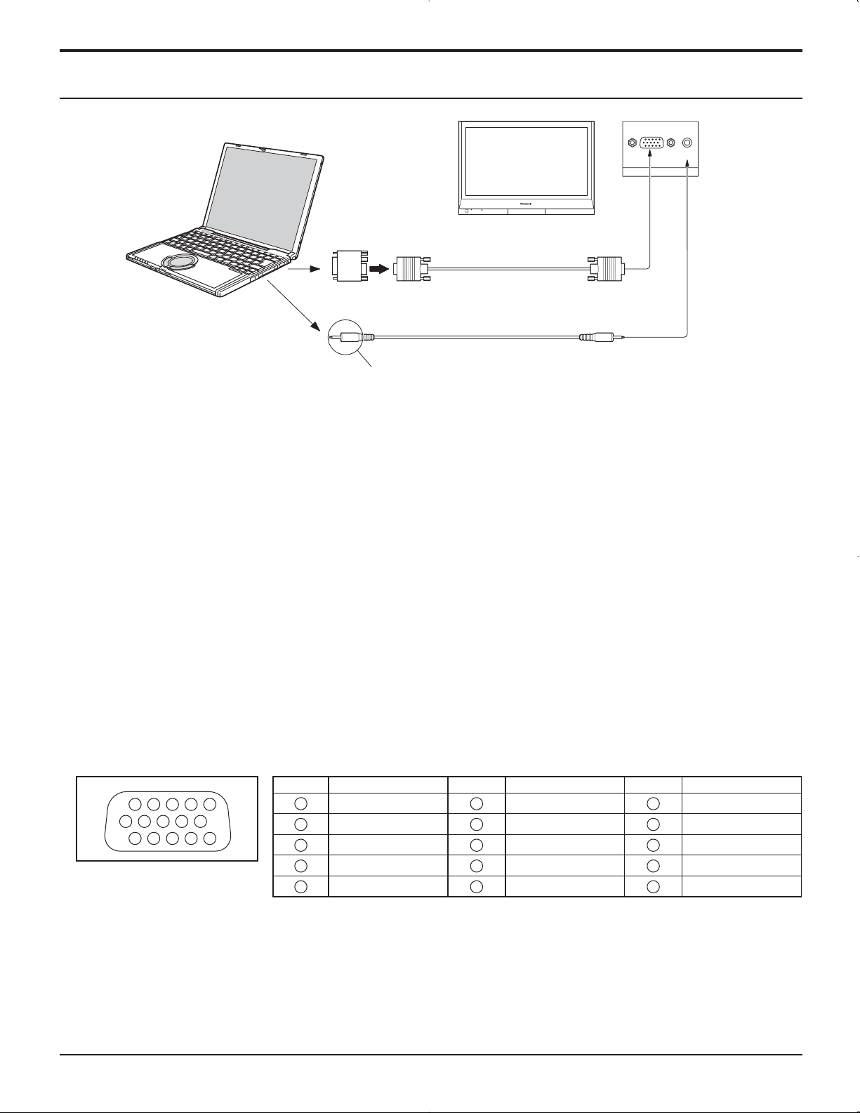
Connections
PC Input Terminals connection
COMPUTER
Conversion adapter
(if necessary)
AUDIO
PC IN
Mini D-sub 15p
RGB
PC cable
Audio
Connect a cable which matches
the audio output terminal on the computer.
Stereo plug
Notes:
• Due to space limitations, occasionally you may have trouble connecting Mini D-sub 15P cable with ferrite core to PC
input Terminal.
• Computer signals which can be input are those with a horizontal scanning frequency of 15 to 110 kHz and vertical scanning
frequency of 48 to 120 Hz. (However, the image will not be displayed properly if the signals exceed 1,200 lines.)
• The display resolution is a maximum of 640 × 480 dots (TH-37PG9U, TH-42PG9U), 768 × 720 dots (TH-37PR9U), 768
× 768 dots (TH-42PR9U) when the aspect mode is set to “NORMAL”, and 852 × 480 dots (TH-37PG9U, TH-42PG9U),
1,024 × 720 dots (TH-37PR9U), 1,024 × 768 dots (TH-42PR9U) when the aspect mode is set to “FULL”. If the display
resolution exceeds these maximums, it may not be possible to show fine detail with sufficient clarity.
• The PC input terminals are DDC1/2B-compatible. If the computer being connected is not DDC1/2B-compatible, you will
need to make setting changes to the computer at the time of connection.
• Some PC models cannot be connected to the set.
• There is no need to use an adapter for computers with DOS/V compatible Mini D-sub 15P terminal.
• The computer shown in the illustration is for example purposes only.
• Additional equipment and cables shown are not supplied with this set.
• Do not set the horizontal and vertical scanning frequencies for PC signals which are above or below the specified
frequency range.
• Component Input is possible with the pin 1, 2, 3 of the D-sub 15P Connector.
Signal Names for Mini D-sub 15P Connector
Pin No.
1514131211
67839
1
2
10
45
Pin Layout for PC Input
Terminal
1
2
3
4
NC (not connected)
5
10
Signal Name
R (PR/CR)
G (Y)
B (PB/CB)
GND (Ground)
Pin No.
6
7
8
9
10
Signal Name
GND (Ground)
GND (Ground)
GND (Ground)
NC (not connected)
GND (Ground)
Pin No.
11
12
13
14
15
Signal Name
NC (not connected)
SDA
HD/SYNC
VD
SCL
Page 11
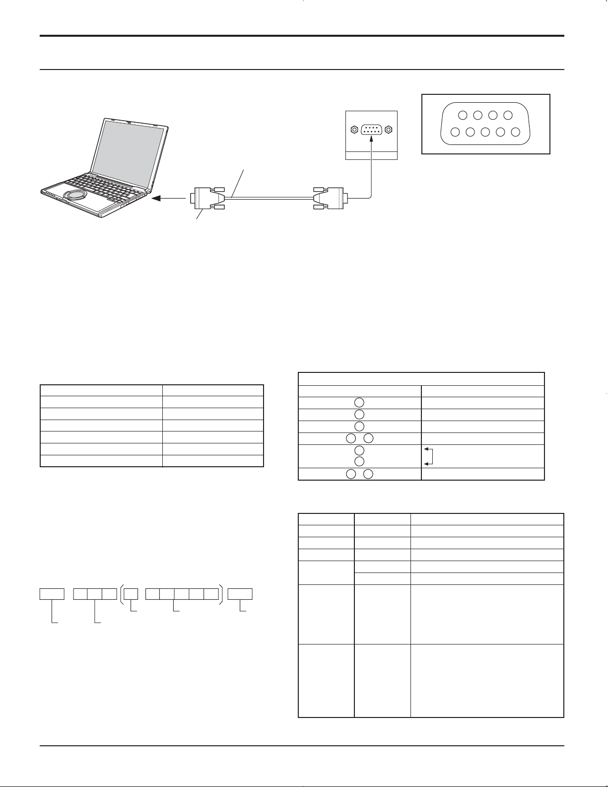
SERIAL Terminals connection
The SERIAL terminal is used when the Plasma Display is controlled by a computer.
Connections
COMPUTER
RS-232C Straight cable
SERIAL
Pin layout for RS-232C
9876
53214
D-sub 9p
Notes:
• Use the RS-232C cable to connect the computer to the Plasma Display.
• The computer shown is for example purposes only.
• Additional equipment and cables shown are not supplied with this set.
The SERIAL terminal conforms to the RS-232C interface specification, so that the Plasma Display can be controlled by a
computer which is connected to this terminal.
The computer will require software which allows the sending and receiving of control data which satisfies the conditions
given below. Use a computer application such as programming language software. Refer to the documentation for the
computer application for details.
Communication parameters
Signal level
Synchronization method
Baud rate
Parity
Character length
Stop bit
Flow control
RS-232C compliant
Asynchronous
9600 bps
None
8 bits
1 bit
-
D-sub 9-pin female Details
R X D
T X D
GND
• Non use
•
RS-232C Conversion cable
2
3
5
6
4
7
8
9
1
Shorted
NC
Basic format for control data
The transmission of control data from the computer
starts with a STX signal, followed by the command,
the parameters, and lastly an ETX signal in that order.
If there are no parameters, then the parameter signal
Command
Command
PON
POF
AVL
does not need to be sent.
AMT
STX C1 C2 C3 P1 P2 P3 P4:P5ETX
Start
(02h)
Colon Parameter(s)
3-character
command (3 bytes)
(1 - 5 bytes)
End
(03h)
IMS
DAM
Notes:
• If multiple commands are transmitted, be sure to wait
for the response for the first command to come from
this unit before sending the next command.
• If an incorrect command is sent by mistake, this unit will
send an “ER401” command back to the computer.
With the power off, this display responds to PON command only.
Parameter
None
None
**
0
1
None
SL1
SL2
SL3
PC1
None
NORM
ZOOM
FULL
JUST
SELF
Control details
Power ON
Power OFF
Volume 00 - 63
Audio MUTE OFF
Audio MUTE ON
Input select (toggle)
Slot1 input
Slot2 input
Slot3 input
PC input
Screen mode select (toggle)
NORMAL (4 : 3)
ZOOM
FULL
JUST
Panasonic AUTO
11
Page 12
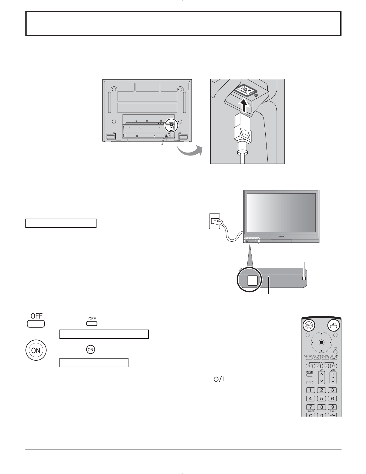
Power ON / OFF
Connecting the AC cord plug to the Plasma Display.
Fix the AC cord plug securely to the Plasma Display
with the clamper. (see page 9)
Connecting the plug to the Wall Outlet
Press the Power switch on the Plasma Display to turn the set
on: Power-On.
Power Indicator: Green
Example: The screen below is displayed for a while after the
Plasma Display is turned on. (setting condition is an
example.)
Press the button on the remote control to turn the Plasma Display off.
Power Indicator: Red (standby)
Press the
Power Indicator: Green
Turn the power to the Plasma Display off by pressing the
when the Plasma Display is on or in standby mode.
button on the remote control to turn the Plasma Display on.
Remote Control Sensor
POWER
Power Indicator
switch on the unit,
12
Note:
During operation of the power management function, the power indicator turns
orange in the power off state.
Page 13
Initial selections
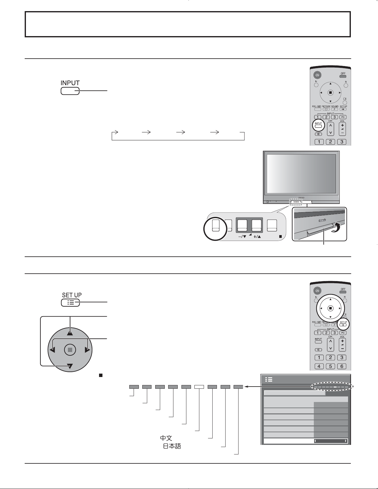
Selecting the input signal
Select the input signals to be connected by installing the optional Terminal Boards.
Press to select the input signal to be played back from
the equipment which has been connected to the Plasma
Display.
Input signals will change as follow:
INPUT1 INPUT2 PC ININPUT3
Notes:
• Selecting is also possible by pressing the INPUT button on the unit.
• Input terminal will not be selected if the terminal board is not installed into the
SLOT.
• Select to match the signals from the source connected to the component/RGB input
terminals. (see page 32)
• In 2 screen display, the same input mode cannot be selected for the main picture
and sub picture.
MENU
INPUT
VOL
ENTER/
Selecting the On-Screen Menu Language
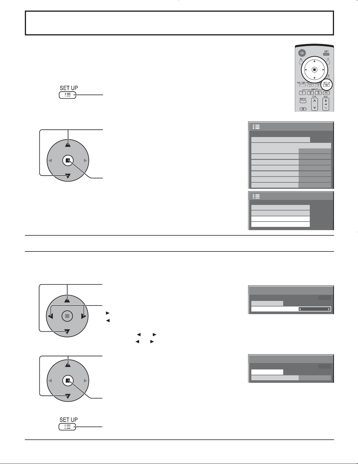
Press to display the SET UP menu.
Press to select OSD LANGUAGE.
Press to select your preferred language.
Selectable languages
English(UK)
Deutsch
Français
Italiano
Español
ENGLISH(US)
.......(Chinese)
.......(Japanese)
Русский
.......(Russian)
COMPONENT/RGB-IN SELECT
INPUT LABEL
POWER SAVE
STANDBY SAVE
POWER MANAGEMENT
AUTO POWER OFF
OSD LANGUAGE ENGLISH (US
Swing up the door at “PULL”.
SET UP
SIGNAL
1/2
RGB
PC
OFF
OFF
OFF
OFF
)
13
Page 14
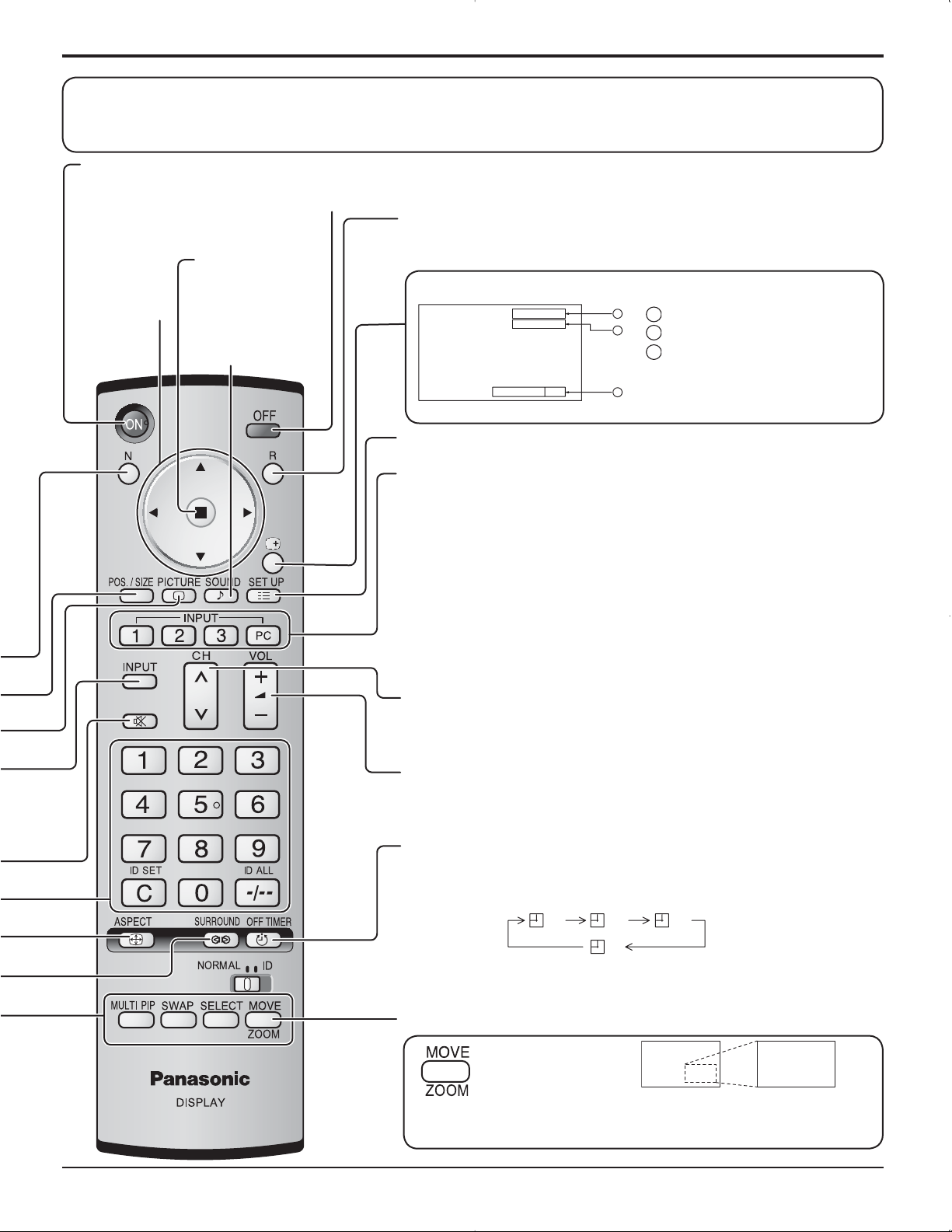
Basic Controls
Remote control sensor
POWER
INPUT
MENU
VOL
INPUT button
(INPUT1, INPUT2, INPUT3 and
PC IN selection)
(see page 13)
ENTER/
Power Indicator
The Power Indicator will light.
• Power-OFF ....Indicator not illuminated (The unit
will still consume some power
as long as the power cord is still
inserted into the wall outlet.)
• Standby ......... Red
• Power-ON ...... Green
• DPMS .............Orange (With PC input signal
and during operation of PC’s
screensaver.)
Main Power On / Off Switch
Volume Adjustment
Volume Up “+” Down “–”
When the menu screen is displayed:
“+” :
press to move the cursor up
“–” :
press to move the cursor down
(see page 16)
Enter / Aspect button
This button is locked by initial setting.
(see page 16, 18)
MENU Screen ON / OFF
This button is locked by initial setting.
Each time the MENU button is pressed, the
menu screen will switch. (see page 16)
Normal Viewing PICTURE SET UP
SOUND POS. /SIZE
N button (see page 19, 22, 23, 24)
POS. /SIZE button (see page 19)
PICTURE button (see page 22)
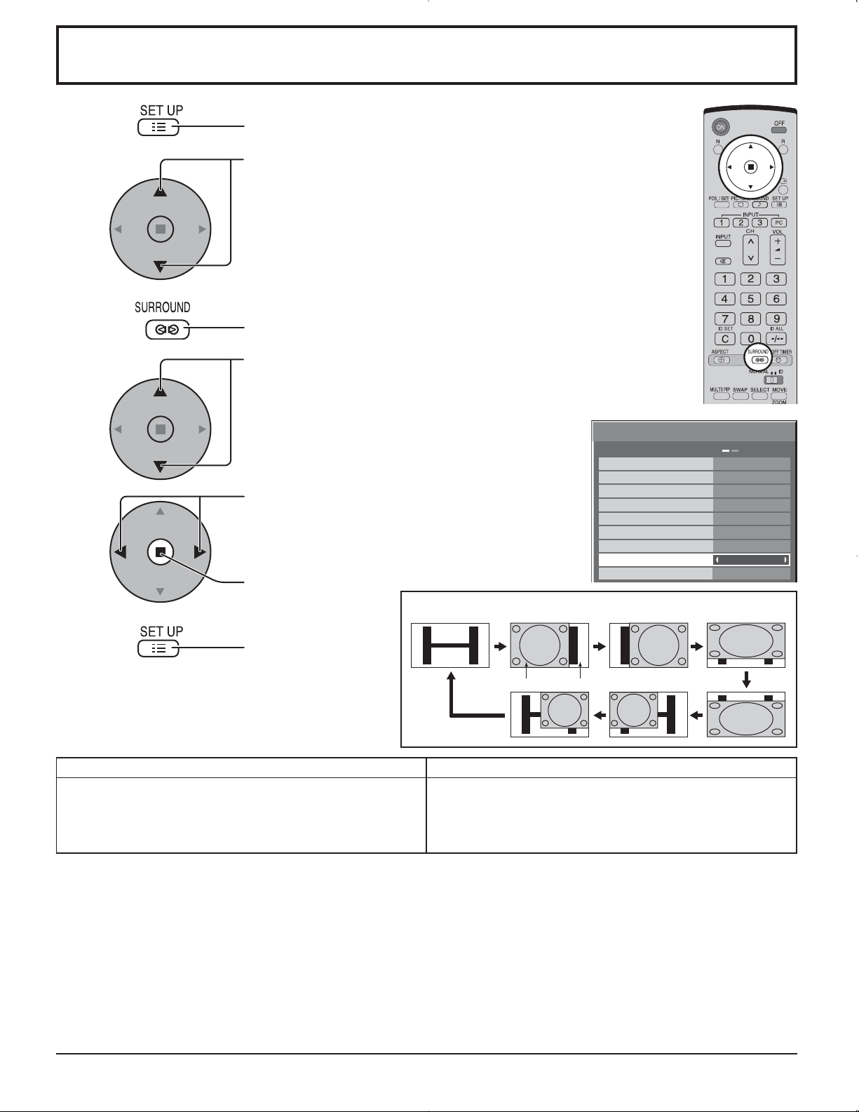
SURROUND button
The surround setting switches on and off each time
the SURROUND button is pressed.
The benefits of surround sound are enormous. You
can be completely enveloped in sound; just as if
you were at a concert hall or cinema.
Note:
The surround settings are memorized separately
for each AUDIO MENU (STANDARD, DYNAMIC,
CLEAR).
ON OFF
SURROUND
ON
14
INPUT button
(INPUT1, INPUT2, INPUT3 and PC IN selection)
Press to select INPUT1, INPUT2, INPUT3 and PC IN input
SLOTS sequentially. (see page 13)
Sound mute On / Off (see page 24)
Numeric buttons (see page 37)
ASPECT button
Press to adjust the aspect. (see page 18)
MULTI Window buttons (see page 20)
Page 15
Basic Controls
The remote control is not included with this set. Available for purchase separately.
Object model : EUR7636070R
Standby (ON / OFF) button
The Plasma Display must first be plugged into the wall outlet and turned on at the power switch (see page 12).
Press ON to turn the Plasma Display On, from Standby mode. Press OFF to turn the Plasma Display Off
to Standby mode.
POSITION
buttons
ACTION button
Press to make
selections.
SOUND button
(see page 24)
R button (see page 17)
Press the R button to return to previous menu screen.
Status button
Press the “Status” button to display the current system status.
PC
NORMAL
1
Input label
1
2
2
Aspect mode (see page 18)
Off timer
3
The off timer indicator is
OFF TIMER 90
3
displayed only when the off
timer has been set.
SET UP button (see page 16, 17)
DIRECT INPUT buttons
Press the INPUT “1”, “2”, “3” or “PC” input mode selection button to
select the INPUT mode.
This button is used to switch directly to INPUT mode.
These buttons can only display the slot which is installed. If you press the button
whose slot is not installed, it automatically displays the current input signal.
Note:
After-image (image lag) may occur on the plasma display panel when
a still picture is kept on the panel for an extended period. The function
that darkens the screen slightly is activated to prevent after-image (see
page 39), this function is not the perfect solution to after-image.
Channel Adjustment
You can use this button when U/V Tuner Board with MATE I/F is installed
(optional accessories). Refer to each Board's Operating Instruction for detail.
Volume Adjustment
Press the Volume Up “+” or Down “–” button to increase or decrease
the sound volume level.
OFF TIMER button
The Plasma Display can be preset to switch to stand-by after a fixed
period. The setting changes to 30 minutes, 60 minutes, 90 minutes and
0 minutes (off timer cancelled) each time the button is pressed.
30 60
90
0
When three minutes remain, “OFF TIMER 3” will flash.
The off timer is cancelled if a power interruption occurs.
Digital Zoom (see page 25)
Press to access
Digital Zoom.
This displays an enlargement of the designated part of the displayed
image.
15
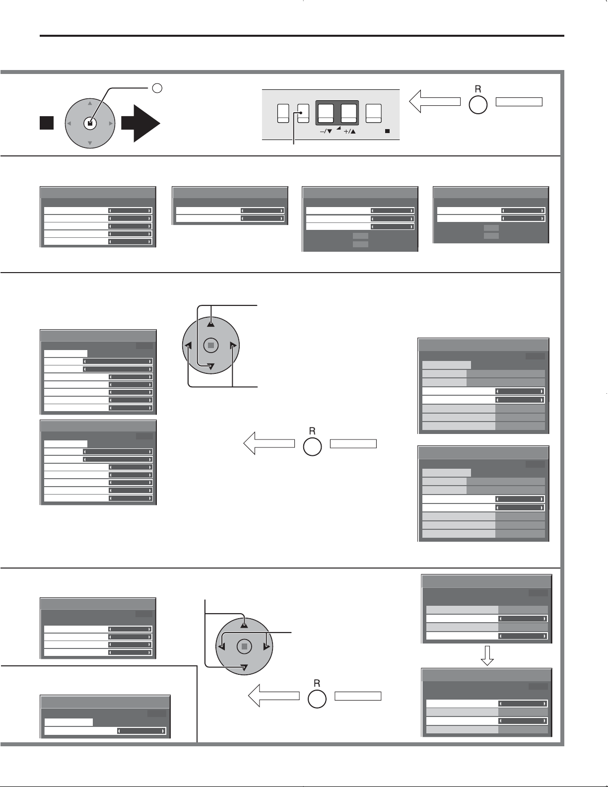
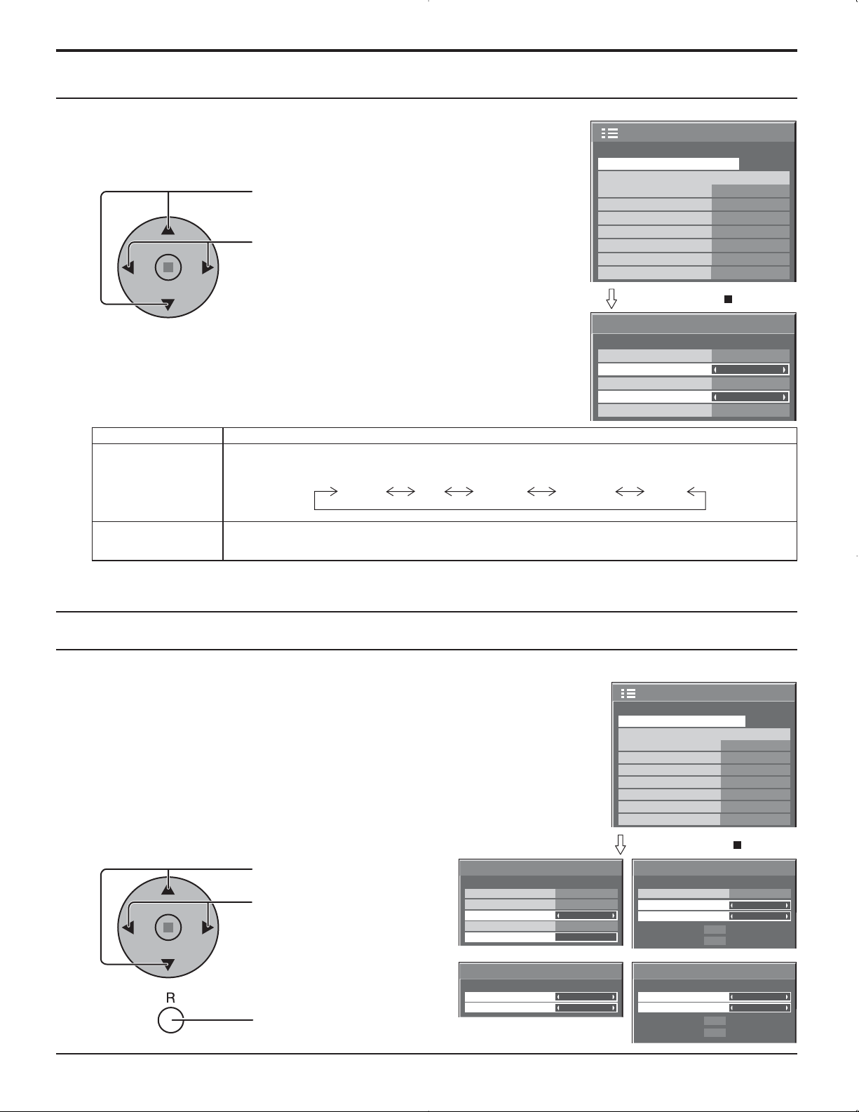
Page 16
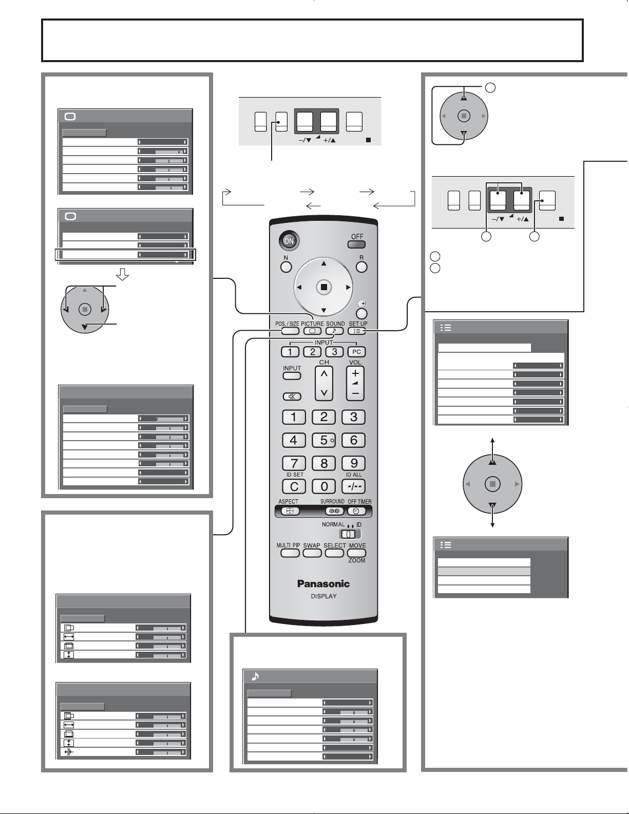
On-Screen Menu Displays
MENU
ENTER/
INPUT
VOL
To PICTURE adjust menu
(see page 22)
1/2PICTURE
PICTURE
NORMAL
STANDARD
25
0
0
0
3
2/2
NORMAL
OFF
ON
NORMALIZE
PICTURE MENU
PICTURE
BRIGHTNESS
COLOR
TINT
SHARPNESS
COLOR TEMP
COLOR MANAGEMENT
ADVANCED SETTINGS
Press to select
“ON”.
Press to enter
ADVANCED
SETTINGS.
To ADVANCED SETTINGS
(see page 22, 23)
ADVANCED SETTINGS
NORMALIZE
BLACK EXTENSION
INPUT LEVEL
W/B HIGH R
W/B HIGH B
W/B LOW R
W/B LOW B
GAMMA
AGC
NORMAL
0
0
0
0
0
0
2.2
OFF
The MENU button on the unit can also be
pressed.
Each time the MENU button is pressed, the
menu screen will switch.
Normal Viewing PICTURE SETUP
SOUND
POS. /SIZE
Press to select .
1
[ from the unit ]
MENU
INPUT
VOL
1
1
Press to select.
2
Press to access each adjust
ENTER/
2
screen.
SET UP
SIGNAL
COMPONENT/RGB-IN SELECT
INPUT LABEL
POWER SAVE
STANDBY SAVE
POWER MANAGEMENT
AUTO POWER OFF
OSD LANGUAGE ENGLISH (US
RGB
PC
OFF
OFF
OFF
OFF
1/2
)
To POS. /SIZE adjust menu (see
page 19)
During “VIDEO (S VIDEO)”,
“COMPONENT” and “DVI” input
signal.
POS. /SIZE
H-POS
H-SIZE
V-POS
V-SIZE
NORMAL
0
0
0
0
NORMALIZE
During “RGB/PC” input signal.
POS. /SIZE
NORMALIZE
NORMAL
H-POS
H-SIZE
V-POS
V-SIZE
CLOCK PHASE
0
0
0
0
0
16
To SOUND adjust menu
(see page 24)
SOUND
NORMALIZE
AUDIO MENU
BASS
MID
TREBLE
BALANCE
SURROUND
AUDIO OUT (PIP)
NORMAL
STANDARD
0
0
0
0
OFF
MAIN
2/2SET UP
SCREENSAVER
MULTI DISPLAY SETUP
SET UP TIMER
PRESENT TIME SETUP
Page 17
On-Screen Menu Displays
2
Press to access
[ from the unit ]
each adjust
screen.
INPUT
MENU
VOL
ENTER/
Press the R button to return
to previous menu.
Press to return to next menu screen.
To SIGNAL screen for VIDEO
(S VIDEO) (see page 32, 33)
SIGNAL
3D Y/C FILTER (NTSC)
COLOR SYSTEM
3 : 2 PULLDOWN
Panasonic AUTO (4 : 3)
VIDEO NR
[
VIDEO
ON
AUTO
OFF
NORMAL
OFF
To SIGNAL screen for
COMPONENT (see page 33)
]
SIGNAL
3 : 2 PULLDOWN
VIDEO NR
[
COMPONENT
OFF
OFF
To SIGNAL screen for RGB
(see page 33, 34)
]
SIGNAL
SYNC
3 : 2 PULLDOWN
VIDEO NR
H-FREQ.
33.8
V-FREQ.
60.0
kHz
Hz
AUTO
OFF
OFF
[
RGB
To SIGNAL screen for DVI
(see page 33, 34)
]
SIGNAL
3 : 2 PULLDOWN
VIDEO NR
H-FREQ.
V-FREQ.
Note: “SIGNAL” setup menu displays a different setting condition for each input signal. (see page 13)
To setup SCREENSAVER
(See page 28-30)
SCREENSAVER
PRESENT TIME OF DAY 99:99
START
FUNCTION
MODE
START TIME
FINISH TIME
SIDE BAR ADJUST
WOBBLING
PEAK LIMIT
SCREENSAVER
START
FUNCTION
MODE
SHOW DURATION
SAVER DURATION
SIDE BAR ADJUST
WOBBLING
PEAK LIMIT
WHITE BAR SCROLL
TIME OF DAY
6:15
12:30
BRIGHT
OFF
OFF
PRESENT TIME OF DAY 99:99
WHITE BAR SCROLL
INTERVAL
6:15
12:30
BRIGHT
OFF
OFF
Press to select START TIME/ FINISH TIME (When TIME OF DAY
is selected).
Press to select SHOW DURATION/ SAVER DURATION (When
INTERVAL is selected).
Press to set up.
Press the R button to return to
“SET UP” menu.
SCREENSAVER
PRESENT TIME OF DAY 99:99
START
FUNCTION
MODE
START TIME
FINISH TIME
SIDE BAR ADJUST
WOBBLING
PEAK LIMIT
WHITE BAR SCROLL
SCREENSAVER
PRESENT TIME OF DAY 99:99
START
FUNCTION
MODE
SHOW DURATION
SAVER DURATION
SIDE BAR ADJUST
WOBBLING
PEAK LIMIT
WHITE BAR SCROLL
kHz
33.8
Hz
60.0
TIME OF DAY
6:15
12:30
BRIGHT
OFF
OFF
INTERVAL
6:15
12:30
BRIGHT
OFF
OFF
[
OFF
OFF
Digital
]
To SET UP TIMER selection
screen. (see page 26, 27)
SET UP TIMER
PRESENT TIME OF DAY 99:99
POWER ON FUNCTION
POWER ON TIME
POWER OFF FUNCTION
POWER OFF TIME
OFF
0:00
OFF
0:00
To PRESENT TIME SETUP.
(see page 26)
PRESENT TIME SETUP
PRESENT TIME OF DAY 99:99
SET
PRESENT TIME OF DAY
99:99
Press to select POWER ON
TIME / POWER OFF TIME.
Press to set up POWER
ON TIME / POWER OFF
TIME.
Press the R button to return to
“SET UP” menu.
SET UP TIMER
PRESENT TIME OF DAY 99:99
POWER ON FUNCTION
POWER ON TIME
POWER OFF FUNCTION
POWER OFF TIME
SET UP TIMER
PRESENT TIME OF DAY 99:99
POWER ON FUNCTION
POWER ON TIME
POWER OFF FUNCTION
POWER OFF TIME
OFF
0:00
OFF
0:00
OFF
0:00
OFF
0:00
17
Page 18
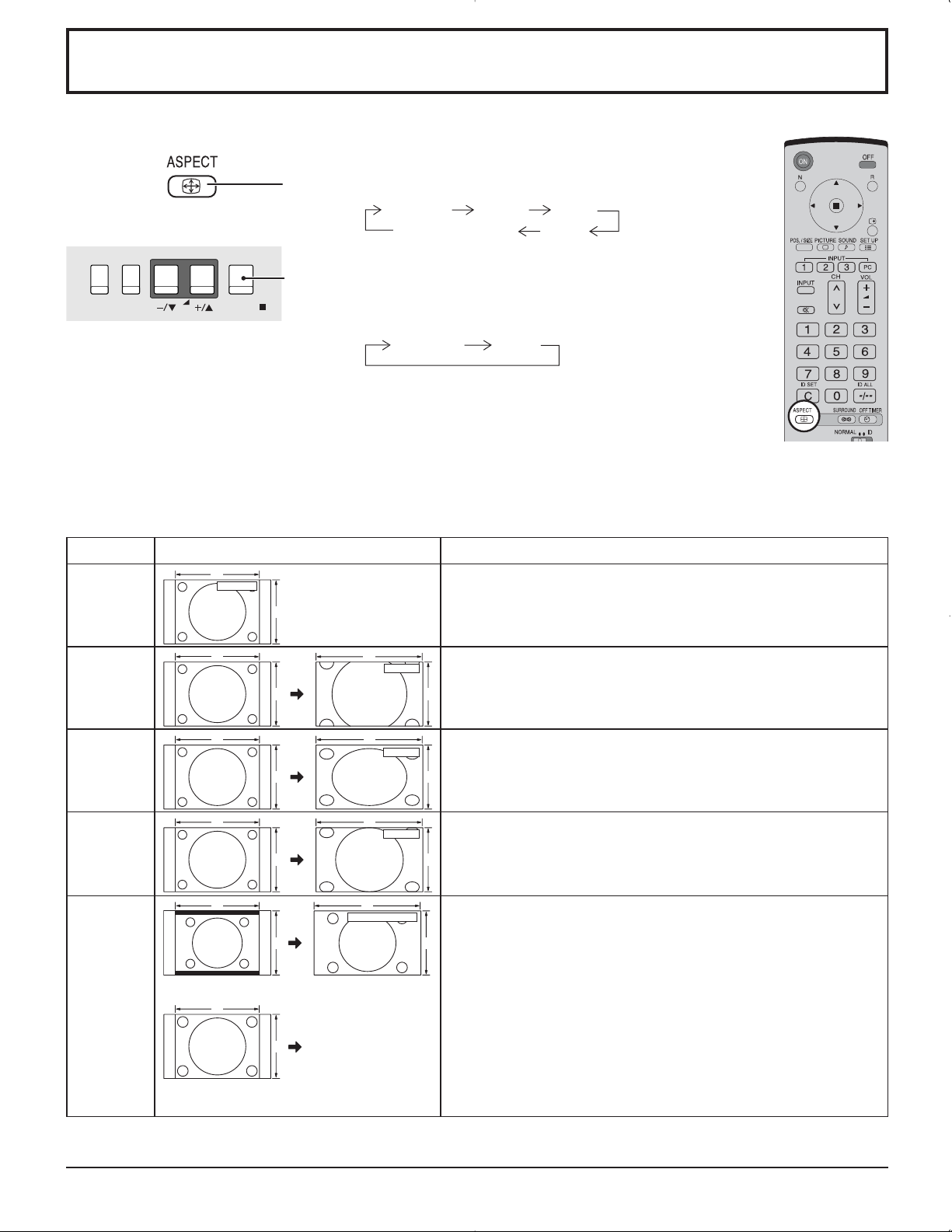
ASPECT Controls
The Plasma Display will allow you to enjoy viewing the picture at its maximum size, including wide screen cinema format
picture.
Press repeatedly to move through the aspect options:
NORMAL ZOOM FULL
[from the unit]
The aspect mode changes each time the ENTER button
INPUT
MENU
VOL
ENTER/
is pressed.
[During MULTI PIP Operations]
• Picture and Picture, Picture in Picture :
• Others : Aspect switching is not possible.
Notes:
• For PC signal input, the mode switches between “NORMAL”, “ZOOM” and “FULL” only.
• For a 1125 (1080) / 60i · 50i · 24p · 25p · 30p · 24sF, 1250 (1080) / 50i, 750 (720) / 60p · 50p signal input, the mode is
set to “FULL” mode, and switching is not possible.
• Panasonic AUTO can be selected only during Video signal input.
• The aspect mode is memorized separately for each input terminal.
Panasonic AUTO JUST
NORMAL FULL
Mode Picture Explanation
NORMAL
ZOOM
FULL
JUST
4
NORMAL
4
4
4
3
16
ZOOM
3
16
FULL
3
16
JUST
3 9
NORMAL will display a 4:3 picture at its standard 4:3 size.
ZOOM mode magnifies the central section of the picture.
9
FULL will display the picture at its maximum size but with slight
elongation.
9
JUST mode will display a 4:3 picture at its maximum size but with aspect
correction applied to the center of the screen so that elongation is only
apparent at the left and right edges of the screen. The size of the picture
will depend on the original signal.
416
39
Panasonic AUTO
The display will automatically become enlarged (depending on the
picture source), allowing you to view the picture at its maximum size.
Notes:
• Panasonic AUTO mode is designed to automatically adjust the aspect
ratio to handle a mix of 16:9 and 4:3 program material. Certain 4:3
Panasonic
AUTO
For an elongated image
4
For a 4:3 image
Image is expanded
Changes in
accordance with the
Panasonic AUTO
3
mode setting (see
page 33).
program material, such as stock market data screens, may occasionally
cause the image size to change unexpectedly. When viewing such
programs, it is recommended that the ASPECT be set to NORMAL.
• If adjusting the PICTURE V-POS/V-SIZE in Panasonic AUTO with FULL
mode, the adjustment is not memorized. When exiting the mode, the
screen will return to a former adjustment.
• Panasonic AUTO can not be selected while TY-FB9BD (optional BNC
Dual Video Terminal Board) is installed.
Note: Do not allow the picture to be displayed in NORMAL mode for an extended period, as this can cause a permanent
after-image to remain on the Plasma Display Panel.
18
Page 19
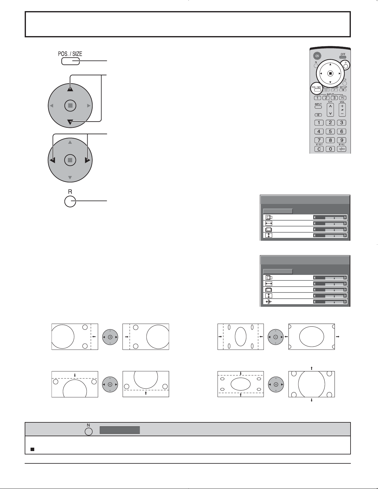
Adjusting POS. /SIZE
1
Press to display the POS. /SIZE menu.
2
Press to select H-POS / H-SIZE / V-POS / V-SIZE /
CLOCK PHASE.
Press to adjust POS. /SIZE.
3
4
Notes:
• Adjustment details are memorized separately for different input signal formats
(Adjustments for component signals are memorized for 525 (480) / 60i · 60p, 625
(575) / 50i · 50p, 1125 (1080) / 60i · 50i · 24p · 25p · 30p · 24sF, 1250 (1080) / 50i,
750 (720) / 60p · 50p each, and RGB/PC/DVI signals are memorized for each
frequency.)
• If a “Cue” or “Rew” signal from a VCR or DVD player is received, the picture position
will shift up or down. This picture position movement cannot be controlled by the
POS. /SIZE function.
• If adjusting the PICTURE V-POS / V-SIZE in Panasonic AUTO with FULL mode,
the adjustment is not memorized. When exiting the mode, the screen will return
to a former adjustment.
Press to exit from adjust mode.
During “VIDEO (S VIDEO)”,
“COMPONENT” and “DVI” input signal.
POS. /SIZE
NORMALIZE
H-POS
H-SIZE
V-POS
V-SIZE
During “RGB / PC” input signal.
POS. /SIZE
NORMALIZE
H-POS
H-SIZE
V-POS
V-SIZE
CLOCK PHASE
NORMAL
0
0
0
0
NORMAL
0
0
0
0
0
H-POS Adjust the horizontal position. H-SIZE Adjust the horizontal size.
V-POS Adjust the vertical position. V-SIZE Adjust the vertical size.
CLOCK PHASE
(RGB/PC in mode)
Helpful Hint ( /
While the POS. /SIZE display is active, if either the N button on the remote control is pressed at any time or the ACTION
( ) button is pressed during “NORMALIZE”, then all adjustment values are returned to the factory settings.
Eliminate the flickering and distortion.
NORMALIZE
Normalization)
19
Page 20
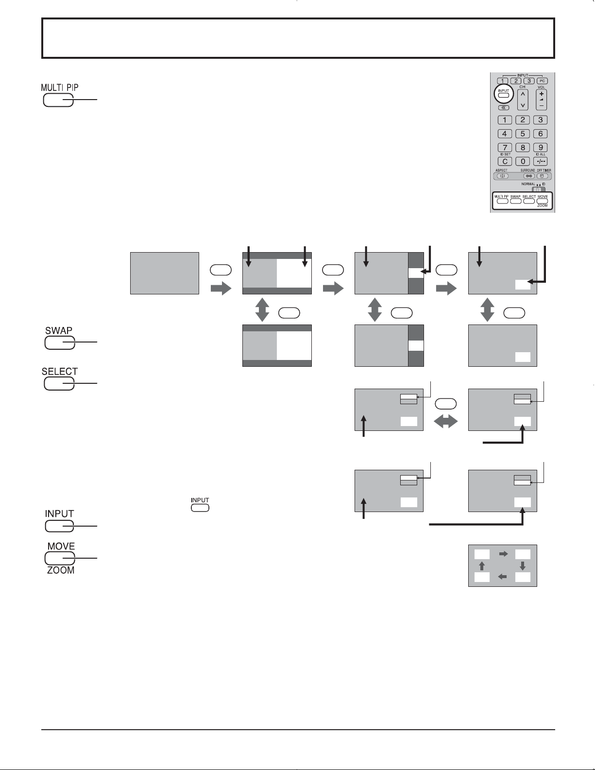
MULTI PIP
Press repeatedly.
Each time pressing this button main picture and sub picture will be displayed
as follows below.
[Picture and Picture] [Picture in Picture]
Main picture Sub picture
MULTI
Normal
Viewing
Press to swap main
picture and sub picture.
Press to select the input mode.
Under main Picture and sub picture display, select
the picture which you would like to change input
modes.
Notes:
• The sub picture sound is heard while a sub
picture operation is underway.
• The sub picture operation automatically returns
to the main picture operation if a sub picture
operation has not been performed for about 3
seconds or if any of the remote control buttons
is pressed (except
PIP
AB
SWAP SWAP SWAP
BA
[Example]
button).
[Picture out Picture]
Main picture Sub picture Main picture Sub picture
MULTI
PIP
A
MULTI
PIP
B
A
B
B
A
B
A
Main picture label is bright Sub picture label is bright
PC1
VIDEO2
A
B
Input modes switching is possible
Main picture label is changed Sub picture label is changed
VIDEO2
VIDEO1
C
B
SELECT
A
A
PC1
VIDEO2
B
PC1
VIDEO2
D
Press to change input signal.
Press to move the sub picture.
Each time the location of the sub picture will be moved.
Notes:
• This button is effective only in the picture in picture.
• The sub picture may be hidden by the on screen display, depending on its position.
Notes:
• Sound output is from the picture which is selected in Audio OUT(PIP) (See page 24).
• In 2 screen display, the same input mode cannot be selected for the main picture and sub picture.
• The main picture and sub picture are processed by different circuits, resulting in a slight difference in the clarity of the
pictures. There may also be a difference in the picture quality of the sub picture depending on the type of signals displayed
on the main picture and depending on the 2-picture display mode.
• Due to the small dimensions of the sub pictures, these sub pictures cannot be shown in detail.
• Computer screen picture is displayed in a simplified format, and it may not be possible to discern details on them
satisfactorily.
• Following combinations of two analog signals cannot be displayed simultaneously.
Component - Component, Component - PC (RGB), PC (RGB) - Component, PC (RGB) - PC (RGB)
Picture is changed
20
Page 21
Advanced PIP
1
2
3
4
5
Press to display the Setup menu.
Press to select “OSD Language”.
Press and hold until the Options menu is displayed.
Press to select Advanced PIP.
Press to adjust the menu.
Off : Sets normal two screen display mode
(see page 20).
On : Sets Advanced PIP mode.
Press to confirm.
Options
Off-timer function
Onscreen display
Initial INPUT
Initial VOL level
Maximum VOL level
INPUT lock
Studio W/B
Advanced PIP
Display size
Enable
Off
Off
1/3
On
Off
0
0
Off
Off
Off
Off
One screen Advanced PIP
6
Notes:
• Advanced PIP corresponding signal
Sub screen Main screen
NTSC, PAL, SECAM (tuner, video)
525i, 525p, 625i, 625p, 750/60p, 750/50p, 1125/60i,
1125/50i, 1250/50i (Component Video, RGB, DVI, SDI,
HDMI)
• Sound output is from the picture which is selected in Audio OUT (PIP) (See page 24).
• In 2 screen display, the same input mode cannot be selected for the main picture and sub picture.
• The main picture and sub picture are processed by different circuits, resulting in a slight difference in the clarity of the
pictures. There may also be a difference in the picture quality of the sub picture depending on the type of signals displayed
on the main picture and depending on the 2-picture display mode.
• Due to the small dimensions of the sub pictures, these sub pictures cannot be shown in detail.
• Computer screen picture is displayed in a simplified format, and it may not be possible to discern details on them
satisfactorily.
• Following combinations of two analog signals cannot be displayed simultaneously.
Component - Component, Component - PC (RGB), PC (RGB) - Component, PC (RGB) - PC (RGB)
• Refer to each board's operating instruction for DVI, SDI, HDMI's corresponding signals.
Press to exit from
Options menu.
Main screenSub screen
640x480@60Hz, 852x480@60Hz, 1024x768@60Hz,
1366x768@60Hz (RGB, DVI, HDMI)
1280x768@60Hz (DVI)
21
Page 22

PICTURE Adjustments
1
Select to adjust each item.
2
PICTURE
NORMALIZE
PICTURE MENU
PICTURE
BRIGHTNESS
COLOR
TINT
SHARPNESS
PICTURE
COLOR TEMP
COLOR MANAGEMENT
ADVANCED SETTINGS
NORMAL
STANDARD
25
0
0
0
3
NORMAL
OFF
ON
Press to display the PICTURE menu.
Press to select the menu to adjust.
Select the desired level by looking at the picture behind
the menu.
1/2
Press the left or right button to switch between modes.
STANDARD
CINEMA DYNAMIC
STANDARD
For viewing in standard (evening lighting) environments.
This menu selects the normal levels of BRIGHTNESS
and PICTURE.
2/2
DYNAMIC
For viewing in brighter environments.
This menu selects higher than normal levels of
BRIGHTNESS and PICTURE.
Press to select “ON”.
CINEMA
Ideal for movies.
Press to enter
Advanced Settings.
ADVANCED SETTINGS ON
Enables fine picture adjustment at a
professional level (see next page).
ADVANCED SETTINGS
NORMALIZE
BLACK EXTENSION
INPUT LEVEL
W/B HIGH R
W/B HIGH B
W/B LOW R
W/B LOW B
GAMMA
AGC
NORMAL
0
0
0
0
0
0
2.2
OFF
ADVANCED SETTINGS OFF
Note:
If you would like to change the picture and color of the selected
PICTURE menu to something else, adjust using the items in
the PICTURE menu. (see next page)
Press the left or right button to switch between modes.
NORMAL COOL WARM
COLOR MANAGEMENT ON
Enables vivid color adjustment automatically.
Displays images with settings of the
PICTURE menu.
Helpful Hint ( /
NORMALIZE
Normalization)
While the “PICTURE” menu is displayed, if either the N button on the remote control is pressed at any time or the ACTION
( ) button is pressed during “NORMALIZE”, then all adjustment values are returned to the factory settings.
22
Page 23
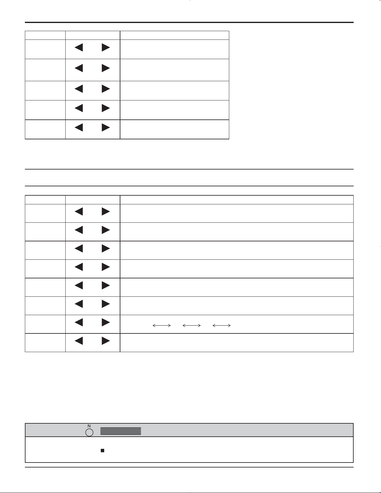
PICTURE Adjustments
Item Effect Adjustments
PICTURE
BRIGHTNESS
COLOR
TINT
SHARPNESS
Less More
Darker Brighter
Less More
Reddish Greenish
Less More
Adjusts the proper picture contrast.
Adjusts for easier viewing of dark
pictures such as night scenes and
black hair.
Adjusts color saturation.
Adjusts for natural flesh tones.
Adjusts picture sharpness.
ADVANCED SETTINGS
Item Effect Details
BLACK
EXTENSION
Less More
Adjusts the dark shades of the image in gradation.
Notes:
• “COLOR” and “TINT” settings cannot be
adjusted for “RGB/PC” and “DVI” input
signal.
•
You can change the level of each function
(PICTURE, BRIGHTNESS, COLOR, TINT,
SHARPNESS) for each PICTURE MENU.
• The setting details for STANDARD,
DYNAMIC and CINEMA respectively
are memorized separately for each input
terminal.
• The “TINT” setting can be adjusted
for NTSC signal only during “VIDEO
(S VIDEO)” input signal.
• In PICTURE, there is not a noticeable
change even when contrast is increased
with a bright picture or reduced with a dark
picture.
INPUT
LEVEL
W/B HIGH R
W/B HIGH B
W/B LOW R
W/B LOW B
GAMMA
AGC
Notes:
• Carry out “W/B” adjustment as follows.
1. Adjust the white balance of the bright sections using the “W/B HIGH R” and “W/B HIGH B” settings.
2. Adjust the white balance of the dark sections using the “W/B LOW R” and “W/B LOW B” settings.
3. Repeat steps 1 and 2 to adjust.
Steps 1 and 2 affect each other’s settings, so repeat each step in turn to make the adjustment.
• The adjustment values are memorized separately for each input terminal.
• The adjustment range values should be used as an adjustment reference.
Less More
Less More
Less More
Less More
Less More
Down Up
OFF ON
Adjustment of parts which are extremely bright and hard to see.
(This cannot be adjusted when the input signal is DVI.)
Adjusts the white balance for light red areas.
Adjusts the white balance for light blue areas.
Adjusts the white balance for dark red areas.
Adjusts the white balance for dark blue areas.
S CURVE 2.0 2.2 2.5
Increases the brightness of dark signal automatically.
Helpful Hint ( /
On the remote control unit, while the “ADVANCED SETTINGS” menu is displayed, if either the N button is pressed at
any time or the ACTION ( ) button is pressed during “NORMALIZE”, then all adjustment values are returned to the
factory settings.
NORMALIZE
Normalization)
23
Page 24
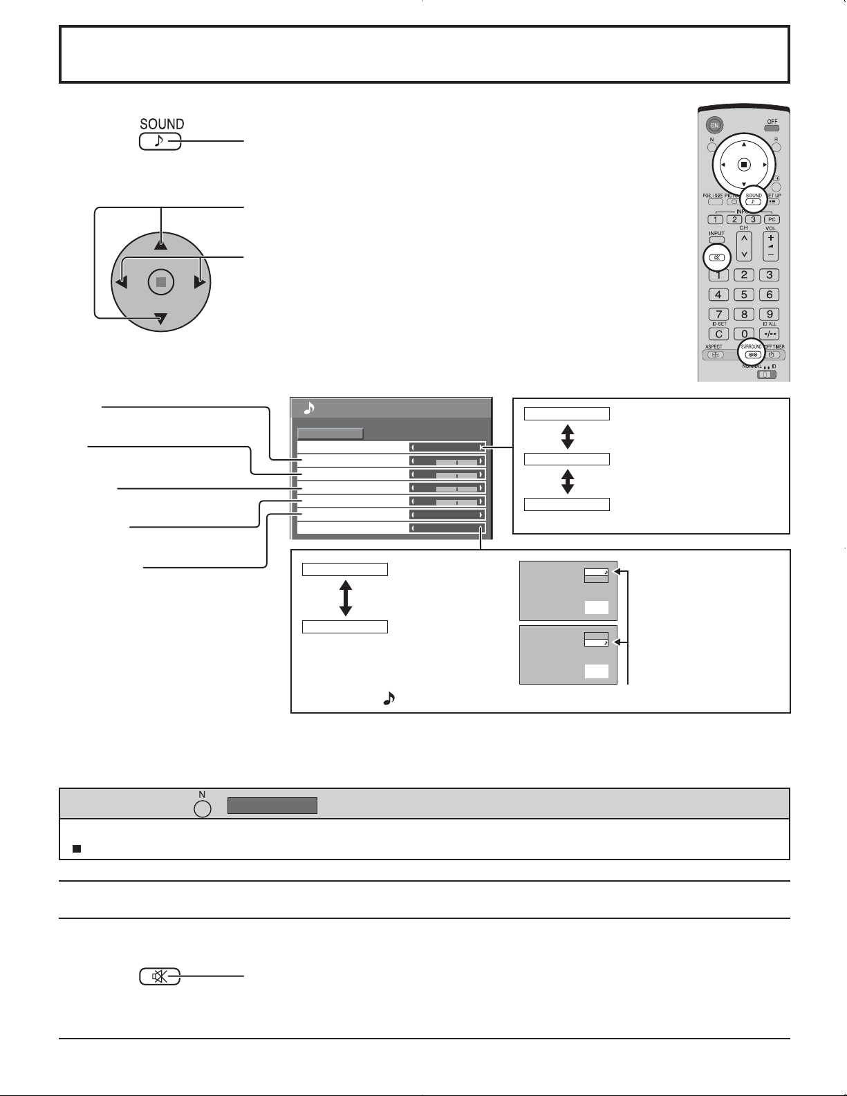
SOUND Adjustment
1
Press to display the SOUND menu.
Select to adjust each item.
2
Press to select the menu to adjust.
Select the desired level by listening to the sound.
BASS
Adjusts low pitch sounds
MID
Adjusts normal sounds
TREBLE
Adjusts pitch sounds
BALANCE
SOUND
NORMALIZE
AUDIO MENU
BASS
MID
TREBLE
BALANCE
SURROUND
AUDIO OUT (PIP)
NORMAL
STANDARD
0
0
0
0
OFF
MAIN
STANDARD
DYNAMIC
CLEAR
Emits the original sound.
Accentuates sharp sound.
Attenuates human voice.
Adjusts left and right volumes
SURROUND
Select On or Off
MAIN
Selects Main
picture sound.
INPUT1
PC
(When Main picture
sound is chosen.)
A
B
SUB
Selects PIP frame
sound.
INPUT1
PC
(When PIP frame
sound is chosen.)
A
B
Musical note is displayed on right side of the audio output screen label.
Notes:
• Press the SURROUND button to directly turn the surround effect ON and OFF. (see page 14)
• BASS, MID, TREBLE and SURROUND settings are memorized separately for each AUDIO MENU.
Helpful Hint ( /
NORMALIZE
Normalization)
While the “SOUND” menu is displayed, if either the N button on the remote control is pressed at any time or the ACTION
( ) button is pressed during “NORMALIZE”, then all adjustment values are returned to the factory settings.
MUTE
Useful when answering the phone or receiving unexpected visitors.
Press this button to mute the sound.
Press again to reactivate sound. Sound is also reactivated when power is turned off or
volume level is changed.
24
Page 25
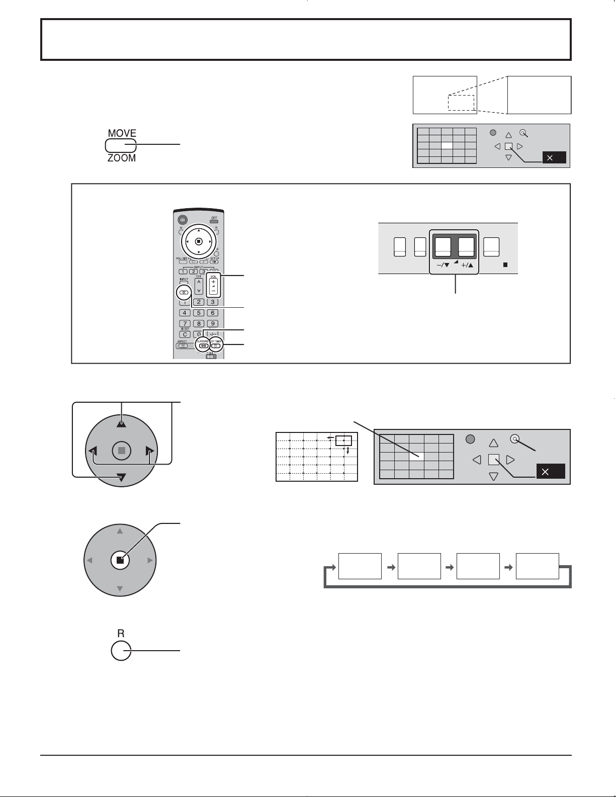
Digital Zoom
This displays an enlargement of the designated part of the displayed image.
1
2
Display the “Operation Guide”.
Press to access Digital Zoom.
The “Operation Guide” will be displayed.
During Digital Zoom, only the following buttons can be operated.
[Remote control]
VOL button
MUTE button
SURROUND button
OFF TIMER button
Select the area of the image to be enlarged.
[Unit]
INPUT
MENU
VOL button
VOL
EXIT
1
ENTER/
Press on the enlargement location to select.
The cursor will move.
3
4
Notes:
• When power goes OFF (including “Off Timer” operation), Digital Zoom terminates.
• The Digital Zoom function cannot be selected while in the following operation state:
“Multi-viewer” (Picture in Picture, Picture out Picture, Picture and Picture) operation. (see page 20)
• While Digital Zoom is in operation, “Adjusting POS. /SIZE” cannot be used.
Select the magnification required for the enlarged display.
Each time this is pressed, the magnification factor changes.
This is shown in the image being displayed.
× 1 × 2 × 3 × 4
Return to normal display (quit Digital Zoom).
Press to exit from the Digital Zoom.
EXIT
2
1
25
Page 26
PRESENT TIME SETUP / SET UP TIMER
The timer can switch the Plasma Display ON or OFF.
Before attempting Timer Set, confirm the PRESENT TIME OF DAY and adjust if necessary.
Then set POWER ON TIME / POWER OFF TIME.
1
2
Press to display the SET UP menu.
Press to select SET UP TIMER or
PRESENT TIME SETUP.
Press to display the SET UP TIMER screen or
PRESENT TIME SETUP screen.
PRESENT TIME SETUP
Display the PRESENT TIME SETUP screen.
SET UP
SIGNAL
COMPONENT/RGB-IN SELECT
INPUT LABEL
POWER SAVE
STANDBY SAVE
POWER MANAGEMENT
AUTO POWER OFF
OSD LANGUAGE ENGLISH(US
SCREENSAVER
MULTI DISPLAY SETUP
SET UP TIMER
PRESENT TIME SETUP
1/2
RGB
PC
OFF
OFF
OFF
OFF
2/2SET UP
)
To set up PRESENT TIME OF DAY, follow the procedure described below.
1
2
3
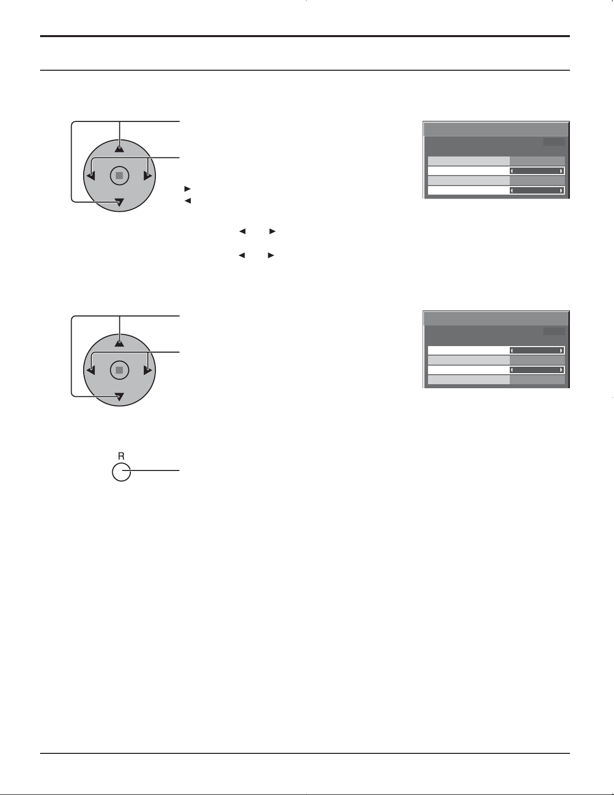
Press to select PRESENT TIME OF DAY.
Press to set up PRESENT TIME OF DAY.
button: Forward
button: Back
Notes:
• Pressing “ ” or “ ” button once changes PRESENT TIME OF DAY 1minute.
• Pressing “ ” or “ ” button continuously changes PRESENT TIME OF DAY by 15 minutes.
Press to select Set.
Press to store PRESENT TIME SETUP.
Note:
Set cannot be selected unless PRESENT TIME OF DAY is set.
Press to exit from PRESENT TIME SETUP.
PRESENT TIME SETUP
PRESENT TIME OF DAY 99:99
SET
PRESENT TIME OF DAY
PRESENT TIME SETUP
PRESENT TIME OF DAY 99:99
SET
PRESENT TIME OF DAY
99:99
99:99
26
Page 27
SET UP TIMER
Display the SET UP TIMER SCREEN.
PRESENT TIME SETUP / SET UP TIMER
1
2
Press to select
POWER ON TIME / POWER OFF TIME.
Press to set up POWER ON TIME / POWER OFF
TIME.
button: Forward
button: Back
Notes:
• Pressing “ ” or “ ” button once changes POWER ON TIME / POWER OFF TIME
1minute.
• Pressing “ ” or “ ” button continuously changes POWER ON TIME / POWER OFF
TIME by 15 minutes.
Press to select POWER ON FUNCTION
/ POWER OFF FUNCTION.
Press to select ON.
SET UP TIMER
PRESENT TIME OF DAY 99:99
POWER ON FUNCTION
POWER ON TIME
POWER OFF FUNCTION
POWER OFF TIME
SET UP TIMER
PRESENT TIME OF DAY 99:99
POWER ON FUNCTION
POWER ON TIME
POWER OFF FUNCTION
POWER OFF TIME
OFF
0:00
OFF
0:00
OFF
0:00
OFF
0:00
3
Note:
Timer function will not work unless “PRESENT TIME OF DAY” is set.
Press twice to exit from SET UP.
27
Page 28
SCREENSAVER (For preventing after-images)
Do not display a still picture, especially in NORMAL mode, for any length of time.
If the display must remain on, a SCREENSAVER should be used.
1
2
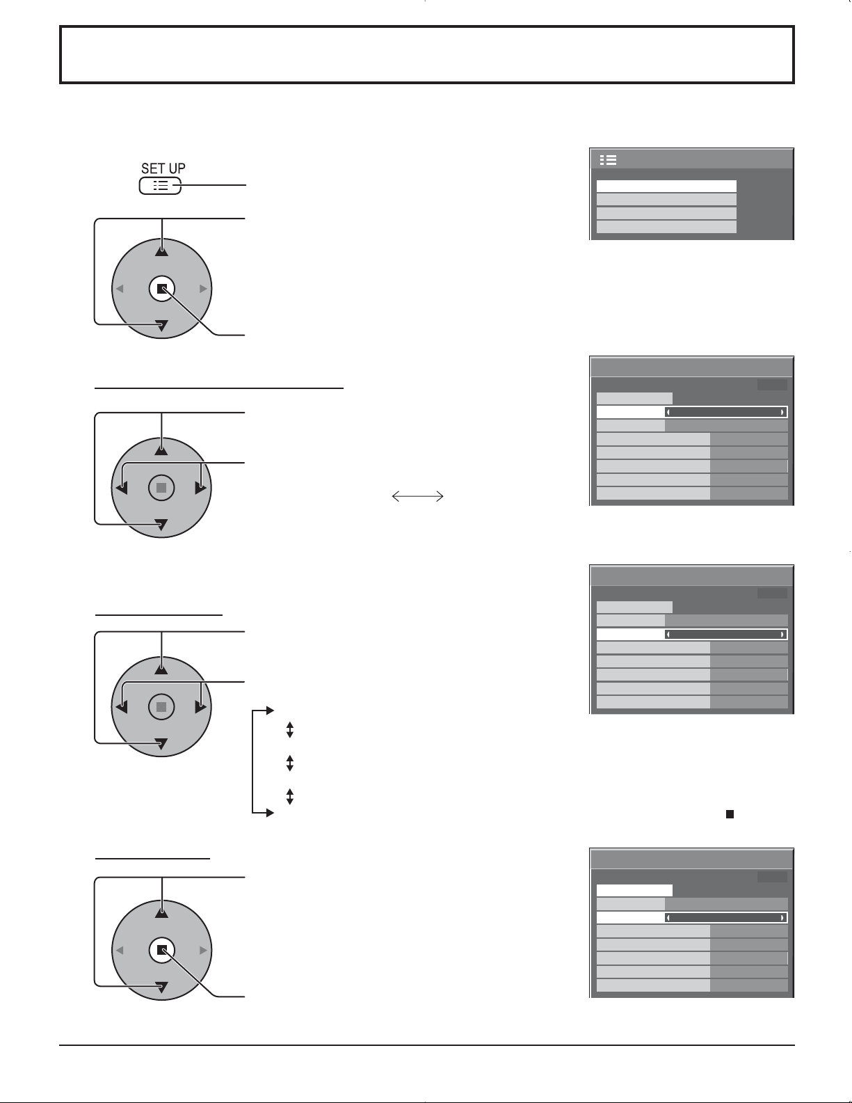
Press to display the SET UP menu.
Press to select the SCREENSAVER.
Press to select the SCREENSAVER screen.
SCREENSAVER
MULTI DISPLAY SETUP
SET UP TIMER
PRESENT TIME SETUP
2/2SET UP
NEGATIVE / SCROLL selection
3
Press to select the FUNCTION.
Press to select the desired function.
WHITE BAR SCROLL NEGATIVE
WHITE BAR SCROLL : A white bar will scroll from left to right.
NEGATIVE : A negative image will be displayed on the screen.
MODE selection
4
Press to select the MODE.
Press to select each mode items.
START setting
5
When the MODE is set to ON, press to select
START.
Press to start SCREENSAVER.
The menu screen will disappear and the SCREENSAVER will be activated. To stop the
SCREENSAVER under ON, press the R button.
SCREENSAVER
PRESENT TIME OF DAY 99:99
START
FUNCTION
MODE
START TIME
FINISH TIME
SIDE BAR ADJUST
WOBBLING
PEAK LIMIT
SCREENSAVER
START
FUNCTION
MODE
START TIME
FINISH TIME
SIDE BAR ADJUST
WOBBLING
PEAK LIMIT
WHITE BAR SCROLL
OFF
6:15
12:30
BRIGHT
OFF
OFF
PRESENT TIME OF DAY 99:99
WHITE BAR SCROLL
OFF
6:15
12:30
BRIGHT
OFF
OFF
OFF
INTERVAL : Operates when SHOW DURATION and SAVER DURATION are
set up and those times arrive.
TIME OF DAY : Operates when START TIME and FINISH TIME are set up and
those times arrive.
ON : Operates when START is selected and the ACTION ( ) button is
pressed.
SCREENSAVER
PRESENT TIME OF DAY 99:99
START
FUNCTION
MODE
START TIME
FINISH TIME
SIDE BAR ADJUST
WOBBLING
PEAK LIMIT
WHITE BAR SCROLL
ON
6:15
12:30
BRIGHT
OFF
OFF
28
Page 29

SCREENSAVER (For preventing after-images)
Setup of SCREENSAVER Time
After selecting TIME OF DAY or INTERVAL, the relevant Time Setup will become available for selection and the Operating
Time may be set. (Time cannot be set when “MODE” is “ON” or “OFF”.)
SCREENSAVER
PRESENT TIME OF DAY 99:99
START
FUNCTION
MODE
START TIME
FINISH TIME
SIDE BAR ADJUST
WOBBLING
PEAK LIMIT
WHITE BAR SCROLL
TIME OF DAY
6:15
12:30
BRIGHT
OFF
OFF
SCREENSAVER
PRESENT TIME OF DAY 99:99
START
FUNCTION
MODE
SHOW DURATION
SAVER DURATION
SIDE BAR ADJUST
WOBBLING
PEAK LIMIT
WHITE BAR SCROLL
INTERVAL
BRIGHT
6:15
12:30
OFF
OFF
Press to select START TIME / FINISH TIME
(When TIME OF DAY is selected).
Press to select SHOW DURATION / SAVER
DURATION (When INTERVAL is selected).
Press to setup.
button: Forward
Notes:
button: Back
• Pressing “ ” or “ ” button once changes the Time 1minute.
[However, switching occurs every 15 minutes when Periodic Time is selected.]
• Pressing “ ” or “ ” button continuously changes the Time by 15 minutes.
SCREENSAVER
PRESENT TIME OF DAY 99:99
START
FUNCTION
MODE
START TIME
FINISH TIME
SIDE BAR ADJUST
WOBBLING
PEAK LIMIT
WHITE BAR SCROLL
TIME OF DAY
0:00
0:00
BRIGHT
OFF
OFF
SCREENSAVER
PRESENT TIME OF DAY 99:99
START
FUNCTION
MODE
SHOW DURATION
SAVER DURATION
SIDE BAR ADJUST
WOBBLING
PEAK LIMIT
WHITE BAR SCROLL
INTERVAL
BRIGHT
0:00
0:00
OFF
OFF
SCREENSAVER
PRESENT TIME OF DAY 99:99
START
FUNCTION
MODE
START TIME
FINISH TIME
SIDE BAR ADJUST
WOBBLING
PEAK LIMIT
WHITE BAR SCROLL
SCREENSAVER
FUNCTION
MODE
START TIME
FINISH TIME
SIDE BAR ADJUST
WOBBLING
PEAK LIMIT
SCREENSAVER
FUNCTION
MODE
SHOW DURATION
SAVER DURATION
SIDE BAR ADJUST
WOBBLING
PEAK LIMIT
OFF
6:15
12:30
BRIGHT
OFF
OFF
PRESENT TIME OF DAY 99:99
START
START
WHITE BAR SCROLL
TIME OF DAY
PRESENT TIME OF DAY 99:99
WHITE BAR SCROLL
INTERVAL
6:15
12:30
BRIGHT
OFF
OFF
6:15
12:30
BRIGHT
OFF
OFF
Note: Timer function will not work unless “PRESENT TIME OF DAY” is set.
Reduces screen after-image
These functions prevent the occurrence of an “after image” on the display when turned ON.
WOBBLING: Automatically shifts the display image at a dot level pitch (therefore unnoticeable to the eye) to prevent
after image of sharper contour of image.
ON1: Shifts the image over time.
ON2: Shifts the image depending on screen-detection.
PEAK LIMIT: Suppresses image contrast (peak brightness).
Note:
When a still picture is viewed for an extended time, the screen may become slightly darker. (see page 39)
1
2
3
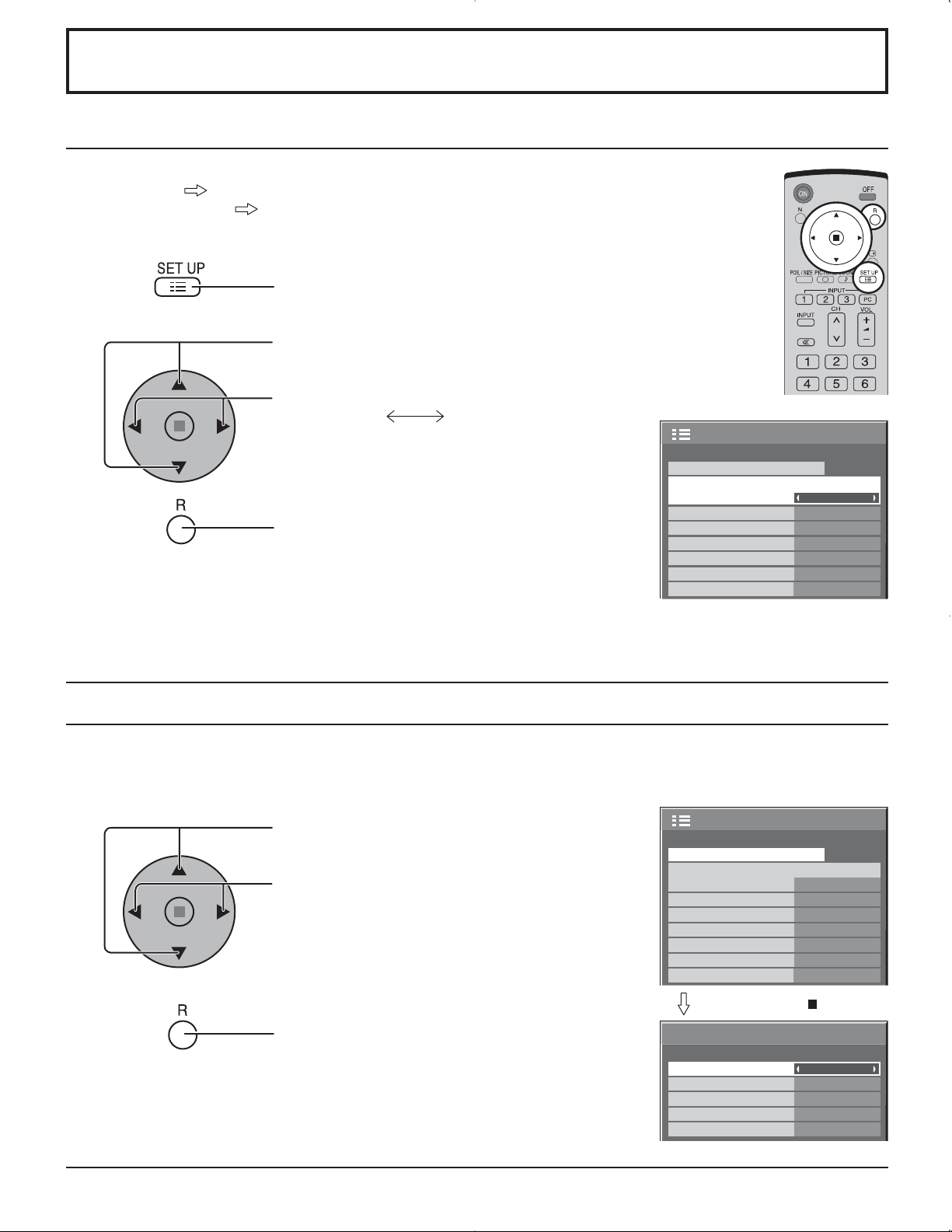
Press to display the SET UP menu.
Press to select “SCREENSAVER”.
Press to display SCREENSAVER menu.
Press to select “WOBBLING” or “PEAK LIMIT”.
Press to select “ON1”, ”ON2” or ”OFF” (WOBBLING).
“ON” or “OFF” (PEAK LIMIT).
SCREENSAVER
MULTI DISPLAY SETUP
SET UP TIMER
PRESENT TIME SETUP
SCREENSAVER
PRESENT TIME OF DAY 99:99
START
FUNCTION
MODE
START TIME
FINISH TIME
SIDE BAR ADJUST
WOBBLING
PEAK LIMIT
WHITE BAR SCROLL
OFF
6:15
12:30
BRIGHT
OFF
OFF
2/2SET UP
29
Page 30

SCREENSAVER (For preventing after-images )
SIDE BAR ADJUST
Do not display a picture in NORMAL mode for an extended
period, as this can cause an after-image to remain on the
side bars on either side of the display field.
To reduce the risk of such an after-image, change the
brightness of the side bars.
This function may be applicable to the non-picture area.
Display the SCREENSAVER screen.
(Refer to the previous page, operation guide steps 1 and 2)
1
Press to select the SIDE BAR ADJUST.
Press to select OFF, DARK, MID, BRIGHT.
OFF MID BRIGHTDARK
side bars
NORMAL mode
after-images
Non picture area
AB
Picture out Picture Picture and Picture
SCREENSAVER
PRESENT TIME OF DAY 99:99
START
FUNCTION
MODE
START TIME
FINISH TIME
SIDE BAR ADJUST
WOBBLING
PEAK LIMIT
WHITE BAR SCROLL
OFF
6:15
12:30
BRIGHT
OFF
OFF
2
Press to exit from SCREENSAVER.
Notes:
• To reduce the occurrence of after-images, set the SIDE BAR ADJUST to BRIGHT.
• The side bar may flash (alternate black/white) depending on the picture being shown on the screen. Using Cinema mode
will reduce such flashing.
30
Page 31

Reduces power consumption
• POWER SAVE: When this function is turned ON, luminous level of the Plasma Display is suppressed, so
power consumption is reduced.
• STANDBY SAVE: When this function is turned ON, power consumption of the microcomputer is reduced during
power supply standby (see page 12, 14-15), so standby power of the set is reduced.
• POWER MANAGEMENT: The unit power supply is turned ON or OFF depending on whether or not there is a signal
during PC input mode.
This function is enabled when it is turned ON. (Only during input from PC(Mini D-sub)
terminal)
• AUTO POWER OFF: Equipment power supply is turned OFF when there is no signal.
When this is set to On, the power supply of the unit goes Off 10 minutes after the input
signals stop.
This function is effective for input signals except input from PC (Mini D-sub) terminal.
1
2
Press to select
“POWER SAVE”
“STANDBY SAVE”
“POWER MANAGEMENT”
“AUTO POWER OFF”.
Press to select “ON” or “OFF”.
On Off
SET UP
SIGNAL
COMPONENT/RGB-IN SELECT
INPUT LABEL
POWER SAVE
STANDBY SAVE
POWER MANAGEMENT
AUTO POWER OFF
OSD LANGUAGE ENGLISH(US
1/2
RGB
PC
OFF
OFF
OFF
OFF
)
Note:
“POWER MANAGEMENT” and “AUTO POWER OFF” are
3
Press to exit from SET UP.
effective during normal viewing (one picture screen) only.
Customizing the Input labels
This function can change the label of the Input signal to be displayed.
SET UP
Press to select INPUT LABEL.
SIGNAL
Note:
Press to change the INPUT LABEL.
COMPONENT/RGB-IN SELECT
INPUT LABEL
POWER SAVE
STANDBY SAVE
POWER MANAGEMENT
AUTO POWER OFF
OSD LANGUAGE ENGLISH(US
While selecting a Input signal through Optional Terminal Board connected to Slot 1, Slot 2 and Slot 3, the Input label will
depend on each Optional Terminal Board.
INPUT LABELS for Slot 1, Slot 2, Slot 3 and miniD-sub:
[Slot1 Input] INPUT1/VIDEO1/COMPONENT1/RGB1/DIGITAL1/PC1/DVD1/CATV1/VCR1/STB1
[Slot2 Input] INPUT2/VIDEO2/COMPONENT2/RGB2/DIGITAL2/PC2/DVD2/CATV2/VCR2/STB2
[Slot3 Input] INPUT3/VIDEO3/COMPONENT3/RGB3/PC3/DVD3/CATV3/VCR3/STB3
[PC (MiniD-sub) input] PC/COMPONENT/RGB/DVD/STB
1/2
RGB
PC
OFF
OFF
OFF
OFF
)
When TY-FB9BD (optional BNC Dual Video Terminal Board) is used, an “A” or “B” is added at the end of each input label,
depending on the input selected (see below).
Addition sign “A” “B”
Selected Input Composite S VIDEO
31
Page 32
SET UP for Input Signals
COMPONENT / RGB IN SELECT
Select to match the signals from the source connected to the COMPONENT / RGB input terminals.
Y, P
, PR signals “COMPONENT”
B
R, G, B, HD, VD signals “RGB”
1
Press to display the SET UP menu.
2
Press to select the “COMPONENT / RGB-IN
SELECT”.
Press to select the desired mode.
COMPONENT RGB
3
Press to exit from adjust mode.
Note:
Selection may not be possible, depending on which optional board is installed.
3D Y/C FILTER – For NTSC AV images
Select “SIGNAL” from the “SET UP” menu during VIDEO (S VIDEO) input signal mode.
(“SIGNAL [VIDEO]” menu is displayed.)
SET UP
SIGNAL
COMPONENT/RGB-IN SELECT
INPUT LABEL
POWER SAVE
STANDBY SAVE
POWER MANAGEMENT
AUTO POWER OFF
OSD LANGUAGE ENGLISH(US
1/2
RGB
PC
OFF
OFF
OFF
OFF
)
1
Press to select the “3D Y/C FILTER (NTSC)”.
Press to set ON / OFF.
2
Press to exit from adjust mode.
Note:
When ON, this setting only affects NTSC input signals.
32
SET UP
COMPONENT/RGB-IN SELECT
INPUT LABEL
POWER SAVE
STANDBY SAVE
POWER MANAGEMENT
AUTO POWER OFF
OSD LANGUAGE ENGLISH(US
SIGNAL
RGB
PC
OFF
OFF
OFF
OFF
Press ACTION ( ) button
SIGNAL
3D Y/C FILTER (NTSC)
COLOR SYSTEM
3 : 2 PULLDOWN
Panasonic AUTO (4 : 3)
VIDEO NR
[
VIDEO
ON
AUTO
OFF
NORMAL
OFF
1/2
)
]
Page 33
SET UP for Input Signals
COLOR SYSTEM / Panasonic AUTO
Select SIGNAL from the “SET UP” menu during VIDEO (S VIDEO) input
SET UP
signal mode.(“SIGNAL [VIDEO]” menu is displayed.)
COMPONENT/RGB-IN SELECT
SIGNAL
Press to select the “COLOR SYSTEM” or “Panasonic
AUTO”.
Press to select each function.
If the image becomes unstable:
With the system set on Auto, under conditions of low
INPUT LABEL
POWER SAVE
STANDBY SAVE
POWER MANAGEMENT
AUTO POWER OFF
OSD LANGUAGE ENGLISH(US
Press ACTION ( ) button
level or noisy input signals the image may in rare
cases become unstable. Should this occur, set the
system to match the format of the input signal.
SIGNAL
3D Y/C FILTER (NTSC)
COLOR SYSTEM
3 : 2 PULLDOWN
Panasonic AUTO (4 : 3)
VIDEO NR
Mode Function
COLOR SYSTEM Set the color system to match the input signal. If set to “AUTO”, the color system is determined
automatically.
AUTO SECAM M.NTSC NTSCPAL
Panasonic AUTO
(4 : 3 )
Set to “NORMAL” to view 4:3 images in an unchanged format when Panasonic AUTO is
selected. If you would like to view 4:3 images in Just format, set to “JUST”.
RGB
PC
OFF
OFF
OFF
OFF
[
VIDEO
ON
AUTO
OFF
NORMAL
OFF
1/2
)
]
Note:
Panasonic AUTO does not function when TY-FB9BD (BNC Dual Video Terminal Board (option)) is used.
3:2 PULLDOWN / VIDEO NR
3:2 PULLDOWN: When ON, the display attempts to reproduce a more natural interpretation of sources such as movie
pictures, which are recorded at 24 frames per second.
If the picture is not stable, turn the setting to OFF.
Notes:
When ON, this setting only affects the following signal input:
• NTSC / PAL signal input during “VIDEO (S VIDEO)” input signal.
• 525i(480i) 625i(575i), 1125(1080)/60i signal input during “COMPONENT” input signal.
VIDEO NR: Automatically reduces unwanted picture noise.
Note:
VIDEO NR cannot be adjusted while a PC signal is being applied.
[
VIDEO
ON
AUTO
OFF
NORMAL
OFF
[
COMPONENT
OFF
OFF
1
2
Press to select 3:2
PULLDOWN or VIDEO NR.
Press to set ON/OFF.
Press to exit from adjust mode.
SIGNAL
3D Y/C FILTER (NTSC)
COLOR SYSTEM
3 : 2 PULLDOWN
Panasonic AUTO (4 : 3)
VIDEO NR
SIGNAL
3 : 2 PULLDOWN
VIDEO NR
SET UP
SIGNAL
COMPONENT/RGB-IN SELECT
INPUT LABEL
POWER SAVE
STANDBY SAVE
POWER MANAGEMENT
AUTO POWER OFF
OSD LANGUAGE ENGLISH(US
Press ACTION ( ) button
]
SIGNAL
SYNC
3 : 2 PULLDOWN
VIDEO NR
H-FREQ.
33.8
V-FREQ.
60.0
]
SIGNAL
3 : 2 PULLDOWN
VIDEO NR
H-FREQ.
33.8
V-FREQ.
60.0
kHz
Hz
kHz
Hz
RGB
PC
OFF
OFF
OFF
OFF
AUTO
OFF
OFF
OFF
OFF
[
[
Digital
1/2
RGB
)
]
]
33
Page 34

SET UP for Input Signals
SYNC
Select SIGNAL from the “SET UP” menu during RGB input signal.
1
2
Press to adjust.
Press to exit from adjust mode.
Setting RGB sync signal
Confirm that the input is set to RGB INPUT (this setting is valid only for RGB INPUT
signal).
AUTO: The H and V sync or synchronized signal are automatically selected.
If both input, it is selected the H and V sync.
ON G: Uses a synchronized signal on the Video G signal, which is input from
the G connector.
VBS: Uses a synchronized signal of Composite Sync input, which is input
from the HD connector.
SET UP
COMPONENT/RGB-IN SELECT
INPUT LABEL
POWER SAVE
STANDBY SAVE
POWER MANAGEMENT
AUTO POWER OFF
OSD LANGUAGE ENGLISH(US
SIGNAL
RGB
PC
OFF
OFF
OFF
OFF
Press ACTION ( ) button
SIGNAL
SYNC
3 : 2 PULLDOWN
VIDEO NR
H-FREQ.
V-FREQ.
SYNC
SYNC
SYNC
33.8
60.0
AUTO
OFF
OFF
kHz
Hz
AUTO
ON G
VBS
[
RGB
1/2
)
]
H-FREQ. (kHz) / V-FREQ. (Hz)
Displays the H (Horizontal) / V (Vertical) frequencies.
This display is valid only for RGB/PC and DVI input signal.
Display range:
Horizontal 15 - 110 kHz
Vertical 48 - 120 Hz
34
H-FREQ.
V-FREQ.
33.8
60.0
kHz
Hz
Page 35

Options Adjustments
1
2
3
4
5
Press to display the Setup menu.
Press to select “OSD Language”.
Press and hold until the Options menu is displayed.
Press to select your preferred menu.
Press to adjust the menu.
Options
1/3
Press to confirm.
6
Press to exit from Options menu.
Item Effect Adjustments
Off-timer
function
Onscreen
display
Initial INPUT
Enable
On Off
Disable
Enable: Switches the “Off-timer function” “On”
Disable: Switches the “Off-timer function” “Off”
Note: When “Disable” is set, the Off-timer is cancelled.
On: Displays all the following on screen.
• Power on display
• Input signal switch display
• No signal display
• Mute and the remaining time of off-timer after
Off: Hides all the items above from view.
Off PC INPUT1 INPUT2 INPUT3
Adjusts the input signal when TV is turned on.
Notes:
• Only the adjusted signal is displayed. (see page 13).
• Signal can be displayed when the Terminal board is installed.
• This menu is available only when “INPUT lock” is “Off”.
was pressed.
Off-timer function
Onscreen display
Initial INPUT
Initial VOL level
Maximum VOL level
INPUT lock
Studio W/B
Advanced PIP
Display size
Enable
Off
Off
On
Off
0
0
Off
Off
Off
Off
35
Page 36
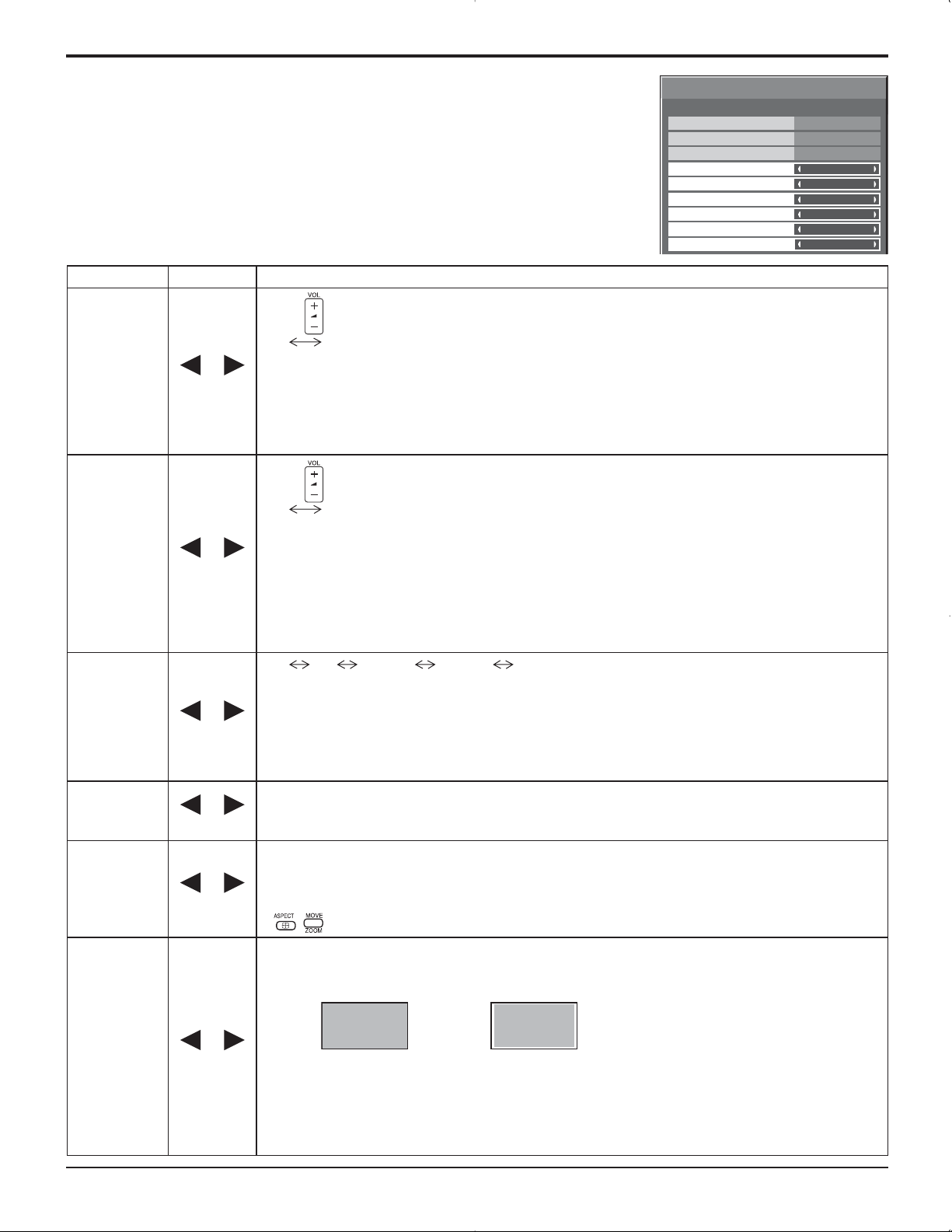
Options Adjustments
Item Effect Adjustments
Press button to adjust the volume when TV is turned on.
Off On
Initial VOL
level
Maximum VOL
level
Off On
Off On
Off: Sets normal volume.
On: Sets your preferred volume.
Notes:
•
When “Maximum VOL level” is “On”, the volume can only be adjusted between 0 and your maximum range.
•
You can hear the changed volume regardless of your volume setting before opening the options menu if you
adjust the volume when “Initial VOL level” is “On” and cursor is on the menu.
Press button to adjust the maximum volume.
Off On
Off: Sets auto maximum volume.
On: Sets your preferred maximum volume.
Notes:
• If the “Maximum VOL level” is set lower than the “Initial VOL level”, the “Initial VOL level” automatically
becomes the same as the “Maximum VOL level”.
• The volume display can go up to 63 regardless of the settings.
•
You can hear the changed volume regardless of your volume setting before opening the options menu if you
adjust the volume when “Maximum VOL level” is “On” and cursor is on the menu.
Options
Off-timer function
Onscreen display
Initial INPUT
Initial VOL level
Maximum VOL level
INPUT lock
Studio W/B
Advanced PIP
Display size
Enable
Off
Off
1/3
On
Off
0
0
Off
Off
Off
Off
INPUT lock
Studio W/B
Advanced PIP
Display size
Off On
Off On
Off On
Off PC INPUT1 INPUT2 INPUT3
Locks the input switch operation.
Notes:
• Only the adjusted signal is displayed (see page 13).
• Signal can be displayed when the Terminal board is installed.
• Input switch can be used when this is set to “Off”.
• In two screen display mode, if anything other than “Off” is set, the value will be fixed as the value
input in the single screen display mode.
Off: Nullify all the settings adjusted.
On: Sets the color temperature for TV studio.
Note: Valid only when the low is set as color temperature on screen adjustment.
Off: Sets normal two screen display mode (see page 20).
On: Sets Advanced PIP mode (see page 21).
Notes:
• When “INPUT lock” is “On”, you cannot use all the two screen display functions.
•
, buttons are unavailable during Advanced PIP mode operation.
Adjusts the image display size on screen.
Off: Sets the normal image display size on screen.
On: Sets the image display size approximately 95 % of the normal image display.
Off On
Notes:
• This setting is valid only when the input signals are as follows; 525i, 525p, 625i, 625p, 750/60p,
750/50p, 1125/60i, 1125/50i, 1125/24sF, 1125/25p, 1125/24p, 1125/30p, 1250/50i (Component Video,
RGB, DVI, SDI, HDMI)
• This setting is invalid when two screen display, digital zoom or Multi screen is selected.
• When Display size is set to “On”, Pos. /Size adjustment cannot be used.
• Refer to each board's operating instruction for DVI, SDI, HDMI's corresponding signals.
36
Page 37

Options Adjustments
Item Effect Adjustments
Off MENU&ENTER On
Off: All the buttons at the bottom of the main unit can be used.
Button lock
Remocon
User level
ID select
Remote ID
Serial ID
Off On
Off On
MENU & ENTER:
Locks
MENU
and
buttons on bottom face of main unit.
ENTER/
On: Locks all the button on bottom face of main unit.
Off User1 User2 User3
Off: You can use all of the buttons on the remote control.
User1:You can only use
, , , , , , , buttons on the remote
control.
User2:You can only use
, , buttons on the remote control.
User3:Locks all the buttons on remote control.
Sets panel ID number when panel is used in “Remote ID” or “Serial ID”.
Set value range: 0 - 100
(Standard value: 0)
Off: Disables ID remote control functions. You can use normal remote control operations.
On: Enable ID remote control functions.
Sets the panel ID Control.
Off: Disables external control by the ID.
On: Enables the external control by the ID.
Options
Button lock
Remocon User level
ID select
Remote ID
Serial ID
2/3
Off
Off
0
Off
Off
Options
Slot power
V. lnstallation
Rotate
Serial Slot Select
3/3
Off
Off
Off
Slot1
Item Effect Adjustments
Off Auto On
Off: Power is not transmitted to the slot power.
Slot Power
Auto: Power is transmitted to the slot power only when main power is on.
On: Power is transmitted to the slot power when main power is on or in the standby state.
Note: In some cases, power is transmitted to the slot power when main power is on or in the standby
state regardless of the slot power setting.
V.Installation
Rotate
Serial Slot
Select
Off On
Off On
Note: This mode is unavailable.
Off: Does not rotate the image.
On: Rotates the image 180 degrees.
Slot1 Slot2 Slot3
Selects the slot which communicates serial.
Note: The setting of an external command can be set only from the fi xed serial terminal (see page 11).
Normalization
When both main unit buttons and remote control are disabled due to the “Button lock”, “Remocon User level” or “Remote
ID” adjustments, set all the values “Off” so that all the buttons are enabled again.
Press the
button on main unit together with button on the remote control and hold for more than 5 seconds. The
“SHIPPING” menu is displayed and the lock is released when it disappears.
37
Page 38

Shipping condition
This function allows you to reset the unit to the factory setting.
1
Press to display the SET UP menu.
2
3
4
Press to select “OSD LANGUAGE”.
Press and hold till the SHIPPING menu is
displayed.
Press to select “YES”.
Press to confirm.
SET UP
COMPONENT/RGB-IN SELECT
INPUT LABEL
POWER SAVE
STANDBY SAVE
POWER MANAGEMENT
AUTO POWER OFF
OSD LANGUAGE ENGLISH(US
SHIPPING
SIGNAL
RGB
PC
OFF
OFF
OFF
OFF
YES
1/2
)
[from the unit]
1 Press the MENU button till the Setup menu is displayed.
2 Press the Volume Up “+” or Down “–” button to select “OSD LANGUAGE”.
3 Press and hold the ENTER button till the SHIPPING menu is displayed.
4 Press the Volume Up “+” or Down “–” button to select “YES”.
5 Press the ENTER button.
Note:
Press the R button to return to SET UP menu when SHIPPING menu is displayed.
38
Page 39
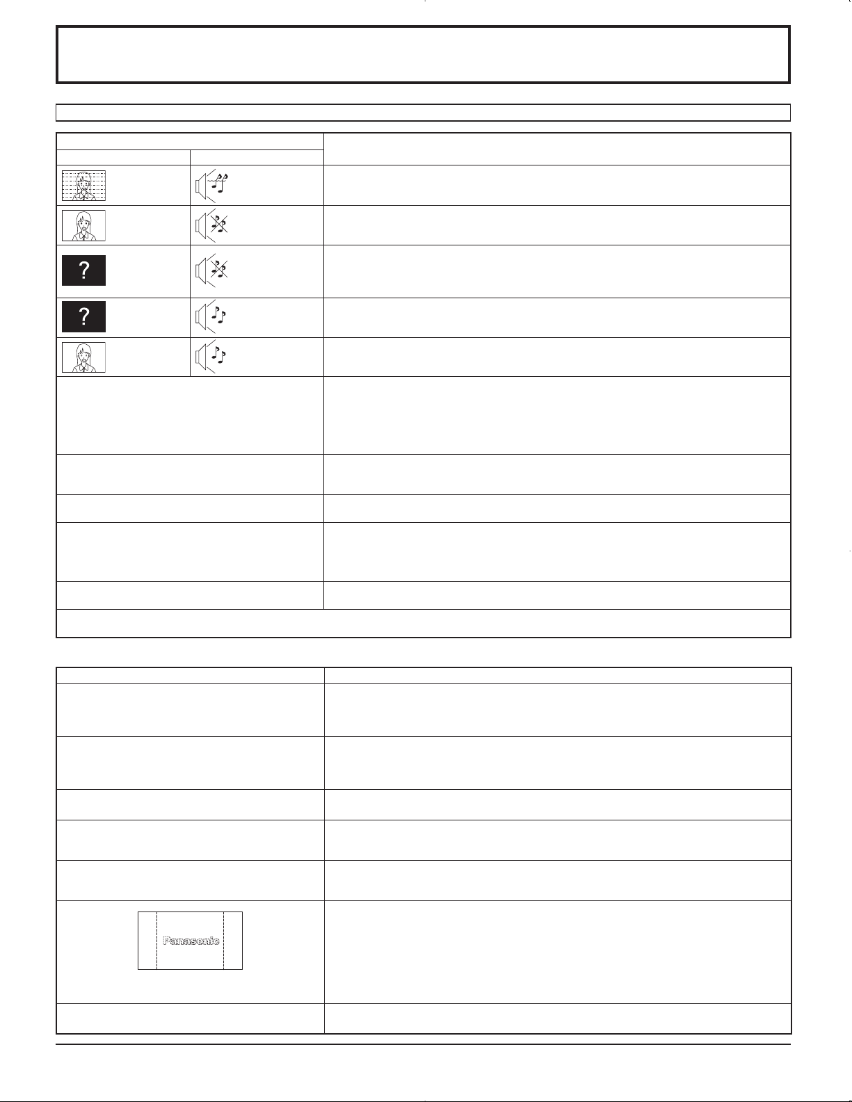
Troubleshooting
Before you call for service, determine the symptoms and make a few simple checks as shown below.
Symptoms
Picture Sound
Interference Noisy Sound
Normal Picture No Sound
No Picture No Sound
No Picture Normal Sound
No Color Normal Sound
No remote control operations can be performed. Check whether the batteries have discharged completely and, if they have not, whether they
A cracking sound is sometimes heard from the unit. If there is nothing wrong with the picture or sound, this is the sound of the cabinet undergoing
The top or bottom of the picture on the screen is cut
off when I use the zoom function.
Areas at the top and bottom of the screen where
the image is missing appear when I use the zoom
function.
Electrical Appliances
Cars / Motorcycles
Fluorescent light
Volume
(Check whether the mute function has been activated on the remote control.)
Not plugged into AC outlet
Not switched on
PICTURE and BRIGHTNESS/Volume setting
(Check by pressing the power switch or stand-by button on the remote control.)
If a signal with a non-applicable color system format, or frequency is input, only the input
terminal indication is displayed.
Color controls set at minimum level. (see page 22, 23)
COLOR SYSTEM (see page 33)
were inserted properly.
Check whether the remote control sensor is exposed to an outdoor light or a strong fluorescent
light.
Check whether the remote control designed specifically for use with the unit is being used.
(The unit cannot be operated by any other remote control.)
very slight contractions in response to changes in the room temperature. There are no adverse
effects on the performance or other aspects.
Adjust the position of the picture on the screen.
When using a video software program (such as a cinema size program) with a screen wider
than one in the 16:9 mode, blank areas separate from the images are formed at the top and
bottom of the screen.
Checks
I can hear sounds coming from inside the unit. When the power is turned on, a sound of the display panel being driven may be heard: This is
This Plasma Display uses special image processing. Hence a slight time lag may occur between image and audio, depending on the type of input
signal. However, this is not a malfunction.
normal and not indicative of malfunctioning.
Plasma Display panel
Symptoms Check
The screen darkens slightly when bright pictures with
minimal movements are shown.
It takes a while for the picture to appear. The unit digitally processes the various signals in order to reproduce esthetically pleasing
The edges of the images flicker. Due to the characteristics of the system used to drive the panel, the edges may appear to flicker
The brightness on both sides of images in NORMAL
mode changes.
Some parts of the screen do not light up. The plasma display panel is manufactured using an extremely high level of precision technology,
After-images appear
[for TH-37PR9U, TH-42PR9U]
Whirring sounds can be heard from the display unit.
The screen will darken slightly when photos, still images of a computer or other pictures with
minimal movements are shown for an extended period. This is done to reduce after-image
on the screen and the shortening of the screen’s service life: It is normal and not indicative of
malfunctioning.
images. As such, it sometimes takes a few moments for the picture to appear when the power
has been turned on, when the input has been switched or when the images for the main picture
and sub picture on the two screens are swapped.
in the fast-moving parts of the images: This is normal and not indicative of malfunctioning.
When viewing the side panels at the “BRIGHT” or “MID” setting, the brightness on both sides
may change depending on the kind of program shown: This is normal and not indicative of
malfunctioning.
however, sometimes some parts of the screen may be missing picture elements or have luminous
spots. This is not a malfunction.
Do not allow a still picture to be displayed for an extended period, as this can cause a permanent
after-image to remain on the Plasma Display.
Examples of still pictures include logos, video games, computer images, teletext and images
displayed in NORMAL mode.
Note:
The permanent after-image on the Plasma Display resulting from fixed image use is not an
operating defect and as such is not covered by the Warranty.
This product is not designed to display fixed images for extended periods of time.
The display unit is fitted with a cooling fan to dissipate heat generated during normal use. The
whirring sound is caused by rotation of the fan and is not a malfunction.
39
Page 40

PC input signals
Applicable input signals for Mini D-sub 15P (Component) / Mini D-sub 15P (RGB) ( Mark)
Signal name
1 525 (480) / 60i 15.73 59.94
2 525 (480) / 60p 31.47 59.94
3 625 (575) / 50i 15.63 50.00
4 625 (575) / 50p 31.25 50.00
5 750 (720) / 60p 45.00 60.00
6 750 (720) / 50p 37.50 50.00
7 1,125 (1,080) / 60i 33.75 60.00
8 1,125 (1,080) / 50i 28.13 50.00
9 1,125 (1,080) / 24p 27.00 24.00
10 1,125 (1,080) / 24sF 27.00 47.92
11 1,125 (1,080) / 25p 28.13 25.00
12 1,125 (1,080) / 30p 33.75 30.00
13 1,250 (1,080) / 50i 31.25 50.00
14 640 × 400 @70 Hz 31.46 70.07
15 640 × 480 @60 Hz 31.47 59.94
16 640 × 480 @72 Hz 37.86 72.81
17 640 × 480 @75 Hz 37.50 75.00
18 640 × 480 @85 Hz 43.27 85.01
19 852 × 480 @60 Hz 31.47 59.94
20 800 × 600 @56 Hz 35.16 56.25
21 800 × 600 @60 Hz 37.88 60.32
22 800 × 600 @72 Hz 48.08 72.19
23 800 × 600 @75 Hz 46.88 75.00
24 800 × 600 @85 Hz 53.67 85.06
25 1,024 × 768 @60 Hz 48.36 60.00
26 1,024 × 768 @70 Hz 56.48 70.07
27 1,024 × 768 @75 Hz 60.02 75.03
28 1,024 × 768 @85 Hz 68.68 85.00
29 1,152 × 864 @75 Hz 67.50 75.00
30 1,280 × 960 @60 Hz 60.00 60.00
31 1,280 × 960 @85 Hz 85.94 85.00
32 1,280 × 1,024 @60 Hz 63.98 60.02
33 1,280 × 1,024 @75 Hz 79.98 75.03
34 1,280 × 1,024 @85 Hz 91.15 85.02
35 1,600 × 1,200 @60 Hz 75.00 60.00
36 1,600 × 1,200 @65 Hz 81.25 65.00
37 1,066 × 600 @60 Hz 37.88 60.32
38 1,366 × 768 @60 Hz 48.36 60.00
39 Macintosh13” (640 × 480) 35.00 66.67
40 Macintosh16” (832 × 624) 49.72 74.54
41 Macintosh21” (1,152 × 870) 68.68 75.06
Horizontal
frequency (kHz)
Vertical
frequency (Hz)
Mini D-sub 15P
(Component)
Mini D-sub 15P
(RGB)
1
2
2
1:
When selected the RGB format and 525p signal input to the Mini D-sub 15P terminal, it is recognized as VGA 60Hz signal.
2:
When inputted VGA 60Hz format signal from the other than Mini D-sub 15P terminal, it is recognized as 525p signal.
Note: Signals without above specification may not be displayed properly.
40
Page 41
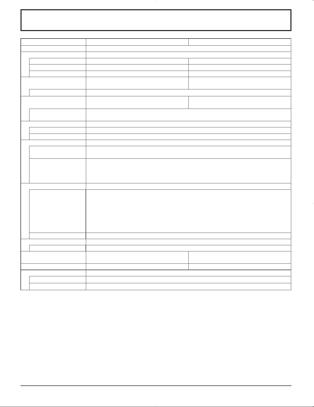
Specifications
TH-37PG9U TH-42PG9U
Power Source 120 V AC, 50/60 Hz
Power Consumption
Power on 265 W 290 W
Stand-by condition Save OFF 0.6 W, Save ON 0.4 W Save OFF 0.6 W, Save ON 0.4 W
Power off condition 0.1 W 0.1 W
Plasma Display panel Drive method : AC type 37-inch,
16:9 aspect ratio
Contrast Ratio Max 10000:1
Screen size 32.2” (818 mm) (W) × 18.1” (461 mm) (H)
× 37” (939 mm) (diagonal)
(No.of pixels) 408,960 (852 (W) × 480 (H))
[2,556 × 480 dots]
Operating condition
Temperature 32 °F - 104 °F (0 °C - 40 °C)
Humidity 20 % - 80 %
Applicable signals
Scanning format 525 (480) / 60i · 60p, 625 (575) / 50i · 50p, 750 (720) / 60p · 50p, 1125 (1080) / 60i · 50i · 24p · 25p
· 30p · 24sF ···· SMPTE274M, 1250 (1080) / 50i
PC signals VGA
SVGA, XGA, SXGA, UXGA ···· (compressed)
Horizontal scanning frequency 15 - 110 kHz
Vertical scanning frequency 48 - 120 Hz
Connection terminals
PC (HIGH-DENSITY Mini-D-SUB 15PIN) R,G,B/0.7 Vp-p (75 ȍ)
HD, VD/1.0 - 5.0 Vp-p (high impedance)
Component
Y : 1.0 Vp-p (75 ȍ : include sync)
P
P
AUDIO IN (M3 JACK) 0.5 Vrms (high impedance)
SERIAL EXTERNAL CONTROL TERMINAL (D-SUB 9PIN) RS-232C COMPATIBLE
Accessories Supplied
Fixing bands (TMME203 or TMME187) × 2
Dimensions (W × H × D)
Mass (weight) approx. 57.3 lbs approx. 66.1 lbs
Sound
Speaker 4.8 ” (120 mm) × 2.4 ” (60 mm) × 2 pcs, 8 ȍ
Audio Output 20W [10 W + 10 W] (10 % THD)
36.1” (917 mm) × 25.4” (644 mm) × 3.7” (95 mm)
(4.3” (109 mm) when including protruding portion of slots)
B/CB : 0.7 Vp-p (75 ȍ)
R/CR : 0.7 Vp-p (75 ȍ)
40.2” (1,020 mm) × 27.8” (705 mm) × 3.7” (95 mm)
(4.3” (109 mm) when including protruding portion of slots)
Drive method : AC type 42-inch,
16:9 aspect ratio
36.2” (920 mm) (W) × 20.4” (518 mm) (H)
× 42” (1,056 mm) (diagonal)
Note:
Design and specifications are subject to change without notice. Mass and dimensions shown are approximate.
41
Page 42

Specifications
TH-37PR9U TH-42PR9U
Power Source 120 V AC, 50/60 Hz
Power Consumption
Power on 300 W 345 W
Stand-by condition Save OFF 0.6 W, Save ON 0.4 W Save OFF 0.6 W, Save ON 0.4 W
Power off condition 0.1 W 0.1 W
Plasma Display panel Drive method : AC type 37-inch,
16:9 aspect ratio
Contrast Ratio Max 10000:1
Screen size 32.2” (818 mm) (W) × 18.1” (461 mm) (H)
× 37” (939 mm) (diagonal)
(No.of pixels) 737,280 (1,024 (W) × 720 (H))
[3,072 × 720 dots]
Operating condition
Temperature 32 °F - 104 °F (0 °C - 40 °C)
Humidity 20 % - 80 %
Applicable signals
Scanning format 525 (480) / 60i · 60p, 625 (575) / 50i · 50p, 750 (720) / 60p · 50p, 1125 (1080) / 60i · 50i · 24p · 25p
· 30p · 24sF ···· SMPTE274M, 1250 (1080) / 50i
PC signals VGA, SVGA,
XGA, SXGA, UXGA ···· (compressed)
Horizontal scanning frequency 15 - 110 kHz
Vertical scanning frequency 48 - 120 Hz
Connection terminals
PC (HIGH-DENSITY Mini-D-SUB 15PIN) R,G,B/0.7 Vp-p (75 ȍ)
HD, VD/1.0 - 5.0 Vp-p (high impedance)
Component
Y : 1.0 Vp-p (75 ȍ : include sync)
P
P
AUDIO IN (M3 JACK) 0.5 Vrms (high impedance)
SERIAL EXTERNAL CONTROL TERMINAL (D-SUB 9PIN) RS-232C COMPATIBLE
Accessories Supplied
Fixing bands (TMME203 or TMME187) × 2
Dimensions (W × H × D)
Mass (weight) approx. 57.3 lbs approx. 66.1 lbs
Sound
Speaker 4.8 ” (120 mm) × 2.4 ” (60 mm) × 2 pcs, 8 ȍ
Audio Output 20W [10 W + 10 W] (10 % THD)
36.1” (917 mm) × 25.4” (644 mm) × 3.7” (95 mm)
(4.3” (109 mm) when including protruding portion of slots)
B/CB : 0.7 Vp-p (75 ȍ)
R/CR : 0.7 Vp-p (75 ȍ)
40.2” (1,020 mm) × 27.8” (705 mm) × 3.7” (95 mm)
(4.3” (109 mm) when including protruding portion of slots)
Drive method : AC type 42-inch,
16:9 aspect ratio
36.2” (920 mm) (W) × 20.4” (518 mm) (H)
× 42” (1,056 mm) (diagonal)
786,432 (1,024 (W) × 768 (H))
[3,072 × 768 dots]
VGA, SVGA, XGA,
SXGA, UXGA ···· (compressed)
Horizontal scanning frequency 15 - 110 kHz
Vertical scanning frequency 48 - 120 Hz
Note:
Design and specifications are subject to change without notice. Mass and dimensions shown are approximate.
42
Page 43

Panasonic Broadcast & Television Systems
Company, Unit of Panasonic Corporation
of North America
One Panasonic Way 2A-4
Secaucus, NJ 07094
Limited Warranty
Panasonic
Puerto Rico, Inc
Ave. 65de Infanteria, Km.9.5
San Gabriel Industrial Park
Carolina, Puerto Rico 00985
Panasonic Broadcast & Television Systems Company or
Panasonic Puerto Rico, Inc (collectively referred to as “the
Warrantor”) will repair this product and all included
accessories with new or refurbished parts, free of charge in
the USA or Puerto Rico, from the original date purchase in
the event of a defect in materials or workmanship as follow:
Warranty
All Monitors, VCRs, Cameras,
Camcorders, P2 Product,
DVDs, Plasma Displays,
switchers and Plug-in
Computers.
Part
Warranty
1 Year 1 Year
Labor
Warranty
Exceptions
D3 & D5 Video Heads
Camera CCD 2 Years 1 Year
Monitor CRT 2 Years 1 Year
All Accessories
Including batteries, cables, and
tapes.
Carry-in or mail-in service in the USA may be obtained
during the warranty period by contacting a Panasonic
Broadcast & Television Systems Company Authorized
Service Center either by using the website
90 days or
500 Hours
10 Days None
90 days or
500 Hours
http://www.panasonic.com/support/
or by calling toll free 1-800-526-6610 to locate the nearest
authorized Service Center.
Carry-in or mail-in service in Puerto Rico can be obtained
during the warranty period by calling 787-750-5135
This warranty is extended only to the original
purchaser and is non transferable. A purchase receipt
or other proof of date of original purchase will be
required before warranty service is rendered.
This warranty only covers failures due to defects in materials
or workmanship, which occur during normal use. The
warranty does not cover damage which occur in shipping or
failures which are caused by products not supplied by the
warrantor, or failures which result from faulty installation,
set-up adjustments, improper antenna, inadequate signal
pickup, maladjustment of user controls, improper operation,
power line surge, improper voltage supply, lighting damage,
or service by anyone other than an authorized repair facility,
or damage that is attributable to acts of God.
LIMITS AND EXCLUSIONS
There are no express warranties except as listed above.
THE WARRANTOR SHALL NOT BE LIABLE FOR
INCIDENTAL OR CONSEQUENTIAL DAMAGES
(INCLUDING, WITHOUT LIMITION, DAMAGE TO
DISCS) RESULTING FROM THE USE OF THIS
PRODUCT, OR ARISING OUT OF ANY BREACH OF
THE WARRANTY. ALL EXPRESS AND IMPLIED
WARRANTIES, INCLUDING THE WARRANTIES OF
MERCHANTABILITY AND FITNESS FOR A
PARTICULAR PURPOSE, ARE LIMITED TO THE
APPLICABLE WARRANTY PERIOD SET FORTH
ABOVE.
Some states do not allow the exclusion or limitation of
incidental or consequential damages, or limitations on how
long an implied warranty lasts, so the above exclusions or
limitations may nor apply to you.
This warranty gives you specific legal rights and you may
also have other rights, which vary from state to state.
If you have a problem with this product that is not handled to
your satisfaction, then write the Consumer Affairs
Department at the Company address indicated above.
In the USA
FOR THE NEAREST SERVICE CENTER FOR TECHNICAL SUPPORT
CALL 1-800-526-6610 CALL 1-800-524-1448
OR OR
Website:
http://www.panasonic.com/support/ Email: pbtscservice@us.panasonic.com
REGISTER YOUR PRODUCT
WWW.PANASONIC.COM/REGISTER
In Puerto Rico
For service call 787-750-5135
Page 44
Panasonic Canada Inc.
Broadcast & Television Systems Division
5770 Ambler Drive, Mississauga, Ontario L4W 2T3
LIMITED WARRANTY STATEMENT
Panasonic Canada Inc. (also known as PCI) warrants this product to be free of
defects in material and workmanship under normal use during the applicable
warranty coverage period described below. PCI agrees to repair, or at its option,
exchange, any part that becomes defective. However, the product must be
purchased and serviced in Canada. The product or part that shows evidence of
defect must be delivered prepaid or carried in to an authorized Panasonic Broadcast
Service Center. This warranty does not cover shipping costs.
The warranty coverage period is one year for both parts and labour beginning with
the date of original end user purchase, subject to the exceptions as stated below.
Repaired or replacement parts supplied during the warranty coverage period carry
the unexpired portion of the original warranty coverage period. Proof of product
purchase is a condition of warranty service. The owner must produce the product
purchase receipt or other satisfactory evidence of date of original purchase.
This warranty does not apply to external appearance items, such as handles, knobs,
safety windows, etc. This warranty does not apply to any part, or parts, of the
product, installed, altered, repaired or misused in any way that, in the opinion of PCI,
affects the reliability of or detracts from the performance of the product.
For products requiring routine preventive maintenance, that maintenance must be
performed in order to maintain warranty coverage.
Serial numbers that have been altered, defaced or removed void this warranty. This
warranty does not cover replacements or repairs necessitated by loss or damage
resulting from any cause beyond the control of PCI.
Marking or retained images (sometimes called “burn-in”) resulting from the display of
fixed images on video display products are not defects and are not covered under
this warranty.
THIS EXPRESS, LIMITED WARRANTY IS IN LIEU OF ALL OTHER
WARRANTIES, EXPRESS OR IMPLIED, INCLUDING ANY IMPLIED
WARRANTIES OF MERCHANTABILITY AND FITNESS FOR A PARTICULAR
PURPOSE. IN NO EVENT WILL PANASONIC CANADA INC. BE LIABLE FOR
ANY SPECIAL, INDIRECT OR CONSEQUENTIAL DAMAGES.
In certain instances, some jurisdictions do not allow the exclusion or limitation of
incidental or consequential damages, or the exclusion of implied warranties, so the
above limitations and exclusions may not be applicable.
WARRANTY COVERAGE PERIOD EXCEPTIONS
Item
Video Tape
P2 Cards
Video Heads
D5 Video heads
Maintenance Items
Colour Camera CCD
Imaging Block
LCD/CRT Monitors
* DLP™ Projectors
* LCD Projectors above
2,500 ANSI Lumens
* LCD Projectors below
2,500 ANSI Lumens
Projector Lamps
Plasma Displays
Hard Drive Disk Unit
≥Dust, smoke, rental/staging environment and twenty-four/seven operation, dramatically
decreases the interval between performances of routine preventive maintenance required
to maintain this warranty coverage.
Warranty Service
If the product needs to be shipped for service, carefully pack (preferably in the
original carton) and enclose a letter, detailing the complaint. Send prepaid and
adequately insured to the local authorized Panasonic Broadcast Service Centre in
your area or to Panasonic Broadcast & Security Systems Service Department, 5770
Ambler Drive, Mississauga, Ontario, L4W 2T3. Shipping to the latter location
requires a return authorization before shipment. No liability is assumed for loss or
damage to the product while in transit.
Parts
30 days— Replacement only
(content not covered)
(Content not covered)
1 year or 2,000 hrs. (prorated)
Whichever comes first
1 year or 500 hrs.
Whichever comes first
90 days
2 years
2 years
3 years or 5,000 hrs.
Whichever comes first
3 years or 2,500 hrs.
Whichever comes first
3 years or 1,500 hrs.
Whichever comes first
90 Days or 500 hrs.
Whichever comes first
1 year (burn-in not covered)
1 year plus balance (if any) of
any original Manufacturer’s
Limited Warranty.
(Content not covered)
Labour
N/A
N/A
1 year or 2,000 hrs.
Whichever comes first
1 year or 500 hrs.
Whichever comes first
90 days
1 year
1 year
3 years or 5,000 hrs.
Whichever comes first
3 years or 2,500 hrs.
Whichever comes first.
3 years or 1,500 hrs.
Whichever comes first
90 Days or 500 hrs.
Whichever comes first.
1 year (burn-in not covered)
1 year
Customer’s Record
The model number and serial number of this product can be found on its back cover. You should note this serial number
in the space provided below and retain this book, plus your purchase receipt, as a permanent record of your purchase
to aid in identification in the event of theft or loss, and for Warranty Service purposes.
Model Number Serial Number
Matsushita Electric Industrial Co., Ltd.
2006 Matsushita Electric Industrial Co., Ltd. All Rights Reserved.
¤
Printed in Japan
MBS0306A1046
Page 45

Page 46

ADVERTENCIA
RIESGO DE DESCARGA ELÉTRICA
NO ABRIR
ADVERTENCIA: Para reducir el riesgo de sufrir una descarga eléctrica, no retire
la cubierta ni el panel posterior. En el interior no hay piezas que deba reparar el
usuario. Solicite las reparaciones al personal de servicio califi cado.
El rayo con punta de fl echa dentro de un
triángulo equilátero tiene la finalidad de
avisar al usuario de que hay piezas en
el interior del producto que si las tocan
las personas éstas pueden recibir una
descarga eléctrica.
El signo de exclamación dentro de un
triángulo equilátero tiene la finalidad
de avisar al usuario de la existencia de
instrucciones de utilización y servicio
importantes en el material impreso que
acompaña al aparato.
ADVERTENCIA : Para impedir los daños que podrían ser causados por una descarga eléctrica, no exponga
este aparato a la lluvia ni a la humedad.
No ponga recipientes con agua (floreros, tazas, cosméticos, etc.) encima del aparato
(incluyendo los estantes que estén encima de él, etc.).
ADVERTENCIA : 1) Para impedir recibir descargas eléctricas, no retire la cubierta. En el interior no hay piezas que
deba reparar el usuario. Solicite las reparaciones al personal de servicio calificado.
2) No quite la clavija de puesta a tierra del enchufe de alimentación. Este aparato está equipado con
un enchufe de alimentación de tres clavijas, una de las cuales sirve para hacer la puesta a tierra.
Este enchufe sólo puede conectarse a un tomacorriente que también disponga de puesta a tierra.
Esto constituye una medida de seguridad. Si no puede introducir el enchufe en el tomacorriente,
póngase en contacto con un electricista.
No anule la finalidad de la clavija de puesta a tierra.
2
Page 47

Instrucciones de seguridad importantes
1) Lea estas instrucciones.
2) Conserve estas instrucciones.
3) Preste atención a todas las advertencias.
4) Siga todas las instrucciones.
5) No utilice este aparato cerca del agua.
6) Limpie solamente con un paño seco.
7) No tape ninguna abertura de ventilación. Instale el aparato según las instrucciones del fabricante.
8) No instale el aparato cerca de fuentes de calor tales como radiadores, salidas de calor, estufas u otros aparatos
(incluyendo amplifi cadores) que produzcan calor.
9) No anule la característica de seguridad de la clavija polarizada o de la clavija del tipo con conexión a tierra. Una
clavija polarizada tiene dos patillas, una más ancha que la otra. Una clavija del tipo con conexión a tierra tiene dos
patillas y una espiga de conexión a tierra. La patilla ancha o la espiga ha sido suministrada para su seguridad. Si
la clavija suministrada no entra en su toma de corriente, consulte a un electricista para que le cambie la toma de
corriente obsoleta.
10) Proteja el cable de alimentación para que no sea pisado ni pellizcado, especialmente en las clavijas, tomas de
corriente y en el punto por donde sale del aparato.
11) Utilice solamente los aditamentos/accesorios que haya especifi cado el fabricante.
12) Utilice el aparato sólo con el mueble con ruedas, soporte, trípode, ménsula o mesa especifi cado
por el fabricante o vendido con el aparato. Cuando utilice un mueble con ruedas, tenga cuidado
al trasladar la combinación del mueble y el aparato para evitar lesionarse si se cae.
13) Desenchufe este aparato durante tormentas eléctricas o cuando no lo utilice durante mucho
tiempo.
14) Solicite todos los trabajos de reparación al personal de servicio cualificado. La reparación del aparato será
necesaria cuando éste se haya estropeado de cualquier forma; por ejemplo, cuando se haya estropeado la clavija
o el cable de alimentación, cuando se haya derramado líquido o hayan caído objetos en el interior del aparato,
cuando el aparato haya quedado expuesto a la lluvia o a la humedad, cuando no funcione normalmente o cuando
se haya caído.
15) Para impedir las descargas eléctricas, asegúrese de que la patilla de puesta a tierra de la clavija del cable de
alimentación de CA esté fi rmemente conectada.
3
Page 48

Estimado cliente de Panasonic
Bienvenido a la familia de clientes de Panasonic. Esperamos que pueda disfrutar durante muchos años
con su nueva Pantalla de plasma.
Para recibir el máximo beneficio de su aparato, lea estas instrucciones antes de hacer ajustes y
guárdelas para consultarlas en el futuro.
Guarde también el recibo y anote el número de modelo y número de serie de su aparato en el espacio
de la cubierta posterior de este manual.
Indice
Instrucciones de seguridad importantes ............... 3
Aviso de seguridad importante ............................... 5
Precauciones para su seguridad ............................ 6
Mantenimiento .......................................................... 7
Accesorios ................................................................ 8
Accesorios suministrados ....................................... 8
Conexiones ............................................................... 9
Conexión de los terminales de entrada PC ........... 10
Conexión de los terminales SERIAL ..................... 11
Encendido/apagado de la alimentación .............. 12
Selecciones iniciales ............................................. 13
Selección de la señal de entrada .......................... 13
Selección del idioma del menú en pantalla .......... 13
Controles básicos .................................................. 14
Indicación en pantalla ........................................... 16
Controles de ASPECTO ......................................... 18
Ajuste de Pos. /Tamaño ......................................... 19
MULTI PIP ............................................................... 20
Advanced PIP (PIP avanzado) .............................. 21
Ajuste de imagen ................................................... 22
Ajustes avanzados ................................................ 23
Ajuste del sonido ................................................... 24
Silenciamiento ...................................................... 24
Zoom digital ............................................................ 25
Puesta de HORA ACTUAL / TEMPORIZADOR ajuste
Puesta de HORA ACTUAL .................................... 26
TEMPORIZADOR ajuste ...................................... 27
.. 26
Protec. pantalla (Para impedir las imágenes
secundarias)
Establecimiento del tiempo de activación
de Protec. Pantalla ................................................ 29
Reducción del efecto de imagen secundaria
en la pantalla ......................................................... 29
Ajuste de paneles laterales ................................... 30
Reducción de consumo de energía ...................... 31
Personalización de las etiquetas de entrada ......... 31
Configuración para las señales de entrada ......... 32
Selección de entrada de señal componente/RGB
Filtro 3D Y/C .......................................................... 32
Sistema de color / Panasonic Auto ........................ 33
Cinema reality / P-NR ............................................ 33
Sincronización ....................................................... 34
Frecuencia horizontal (kHz)/
Frecuencia vertical (Hz) ........................................ 34
Ajustes de Options (Opciones) ............................. 35
Estado de transporte.............................................. 38
Localización de averías .........................................39
Señales de entrada de PC
Especificaciones .................................................... 41
.............................................................. 28
.. 32
....................................... 40
4
Page 49
Aviso de seguridad importante
Este equipo ha sido probado y ha demostrado cumplir con los límites establecidos para dispositivos digitales de la Clase
B, de conformidad con el Apartado 15 de las Normas de la FCC. Estos límites han sido diseñados para proporcionar
una protección razonable contra las interferencias perjudiciales en una instalación residencial. Este equipo genera,
utiliza y puede radiar energía radioeléctrica, y si no se instala y utiliza de acuerdo con las instrucciones, puede causar
interferencias perjudiciales en las comunicaciones por radio. Sin embargo, no existe ninguna garantía de que las
interferencias no se produzcan en una instalación particular. Si este equipo causa interferencias perjudiciales en la
recepción de la radio o la televisión, lo que puede determinarse apagando y encendiendo el equipo, al usuario se le
recomienda intentar corregir la interferencia tomando una o más de las medidas siguientes:
• Cambie la orientación o el lugar de instalación de la antena.
• Aumente la separación entre el equipo y el receptor.
• Conecte el equipo a una toma de corriente diferente de aquella a la que está conectada el receptor.
• Consulte a su concesionario o a un técnico con experiencia para solicitar su ayuda.
Este aparato cumple con el Apartado 15 de las Normas de la FCC. El funcionamiento está sujeto a las dos
condiciones siguientes: (1) Este aparato no debe causar interferencias perjudiciales, y (2) debe aceptar cualquier
interferencia recibida, incluyendo aquellas que puedan causar un funcionamiento no deseado.
AVISO DE LA FCC:
Cualquier cambio o modifi cación que se hiciera sin contar con la aprobación de Panasonic Corporation of
North America podría causar interferencias perjudiciales y anularía la autorización que tiene el usuario para
utilizar este dispositivo.
Declaración de conformidad de la FCC
Número de modelo TH-37PG9U, TH-42PG9U, TH-37PR9U, TH-42PR9U
Responsable: Panasonic Corporation of North America
One Panasonic Way, Secaucus, NJ 07094
Dirección de contacto: Panasonic Broadcast & Television Systems Company
1-800-524-1448
email: pbtscservice@us.panasonic.com
AVISO PARA CANADÁ:
Este aparato digital de la Clase B cumple con la norma canadiense ICES-003.
Nota:
No permita que una imagen fi ja se visualice durante mucho tiempo porque esto podrá ser la causa de que quede
una imagen secundaria en la pantalla panorámica de plasma.
Los ejemplos de imágenes fi jas incluyen logotipos, videojuegos, imágenes de computadora, teletexto e imágenes
mostradas en el formato 4:3.
Marcas comerciales y registradas
• VGA es una marca comercial de International Business Machines Corporation.
• Macintosh es una marca registrada de Apple Computer, EE.UU.
• S-VGA es una marca registrada de Video Electronics Standard Association.
Aunque no se mencionen especialmente marcas comerciales de compañías o productos, tales marcas
comerciales están plenamente reconocidas.
5
Page 50

Precauciones para su seguridad
PRECAUCION
Esta la pantalla de plasma puede utilizarse sólo con los siguientes accesorios opcionales. El uso con cualquier
otro tipo de accesorios opcionales puede causar inestabilidad y terminar provocando daños.
(Matsushita Electric Industrial Co., Ltd. fabrica todos los accesorios siguientes.)
• Pedestal ...................................................................................................................... TY-ST09GR-K
• Abrazadera de suspensión de pared (vertical) ........................................................... TY-WK42PV3U
• Abrazadera de suspensión de pared (angular) .......................................................... TY-WK42PR2U, TY-WK42PR3U
• Tablero de terminales de video componente BNC ..................................................... TY-42TM6A
• Tablero de terminales de video compuesto BNC ....................................................... TY-42TM6B
• Tarjeta de terminales de vídeo dual BNC ................................................................... TY-FB9BD
• Tarjeta de terminales pasante Ir ................................................................................. TY-FB9RT
• Tablero de terminales de video componente RCA ..................................................... TY-42TM6Z
• Tablero de terminales de video compuesto RCA ........................................................ TY-42TM6V
• Tablero de terminales de entrada de PC .................................................................... TY-42TM6P
• Tablero de terminales de (digiral) RGB ...................................................................... TY-42TM6D
• Tablero de terminales HDMI ....................................................................................... TY-FB8HM
• Tarjeta de sintonizador U/V con MATE I/F .................................................................. TY-FB9TU
(excepto para Canadá)
Solicite ayuda de un técnico cualificado para realizar la instalación.
Las partes pequeñas pueden presentar un peligro ya que la persona puede atorarse si dichas partes se tragan
accidentalmente. En consecuencia, mantenga estas partes fuera del alcance de los niños pequeños. Tire las partes
pequeñas y objetos, incluyendo materiales para embalaje y bolsas/ papeles de plástico, para que los niños pequeños no
jueguen, ya que si lo hicieran corren un riesgo potencial de sofocación.
Cuando utilice la pantalla de plasma
No acerque sus manos, rostro u otros objetos cerca de
los orificios de ventilación de la pantalla de plasma.
• El aire que sale de los orificios de ventilación y de la parte
superior de la pantalla de plasma está caliente. No acerque
sus manos, cara u objetos que no puedan soportar el
calor, a estos orificios porque puede quemarse.
Desconecte todos los cables antes de mover la pantalla
de plasma.
• Si fuera necesario mover la pantalla de plasma a otro
lugar y se dejan algunos cables conectados, éstos
pueden dañarse, provocar un incendio o una descarga
eléctrica.
Desenchufe el cable eléctrico del tomacorriente como
medida de seguridad antes de realizar una limpieza.
• Puede sufrir una descarga eléctrica si no lo hace.
Limpie el cable eléctrico a intervalos regulares para
evitar que se cubra por el polvo.
• Si hay acumulación de polvo en el enchufe del cable
eléctrico, la humedad puede acumularse y dañar el
aislamiento, provocando un incendio. Desenchufe el
cable eléctrico del tomacorriente y limpie con un paño
seco.
Esta pantalla de plasma radia rayos infrarrojos, y por lo
tanto puede afectar a otros equipos de comunicación
por infrarrojos. Instale su sensor de infrarrojos en un
lugar alejado de la luz directa de su pantalla de plasma
o de la luz reflejada por ella.
Nota:
No permita que una imagen fija se visualice durante mucho
tiempo porque esto podrá ser la causa de que quede una
imagen secundaria en la pantalla panorámica de plasma.
Los ejemplos de imágenes fijas incluyen logotipos,
videojuegos, imágenes de computadora, teletexto e
imágenes mostradas en el formato 4:3.
6
Page 51

ADVERTENCIA
Precauciones para su seguridad / Mantenimiento
Instalación
No instale la pantalla de plasma sobre superficies
inclinadas o poco estables.
• La pantalla de plasma puede caerse o darse vuelta.
No coloque objetos encima de la pantalla de plasma.
• Si se derrama agua en la pantalla de plasma o entran
objetos extraños en su interior, se puede provocar un
cortocircuito que causará fuego o descarga eléctrica. Si
entran objetos extraños en el interior de la pantalla de
plasma, consulte con su tienda local de Panasonic.
No cubra los orificios de ventilación.
• La pantalla de plasma puede calentarse excesivamente
provocado fuego o daños en la Pantalla de plasma.
Si se utiliza un pedestal (accesorio opcional), deje un
espacio de 3
izquierda y derecha, 2
inferior y 2
se utiliza algún otro método de instalación, deje un
espacio de 3
inferior, izquierda y derecha y 2
parte posterior.
15/16” (10 cm) o más en la parte superior,
3/8” (6 cm) o más en la parte
3/4” (7 cm) o más en la parte posterior. Si
15/16” (10 cm) o más en la parte superior,
3/4” (7 cm) o más en la
Cuando utilice la pantalla de plasma
La pantalla de plasma fue diseñada para funcionar con
una CA de 120 V, 50/60 Hz.
Inserte completamente el enchufe del cable eléctrico.
• Si el enchufe no ha entrado completamente puede
generar calor y ser el origen de un incendio. Si el
enchufe está dañado o el tomacorriente está flojo, no
los utilice.
No haga nada que pueda dañar el cable eléctrico.
Cuando desenchufe el cable eléctrico, sujete del
enchufe y no el cable.
• No dañe el cable eléctrico, no lo modifique ni coloque
objetos pesados encima, ni coloque cerca de objetos
que desprendan calor, no tuerza ni tire excesivamente
del mismo. Esto puede provocar un fuego o descarga
eléctrica. Si el cable eléctrico está dañado, solicite la
reparación en su tienda local de Panasonic.
Si no se utiliza la pantalla de plasma durante un largo
período de tiempo, desenchufe el cable eléctrico del
tomacorriente.
Si se producen problemas durante el uso
Si se produce un problema (por ejemplo falta la imagen
o sonido), o si sale humo o hay olores no normales de
la pantalla de plasma, desenchufe inmediatamente el
cable eléctrico del tomacorriente.
• Si sigue utilizando la pantalla de plasma en estas
condiciones, puede provocar un fuego o descarga
eléctrica. Después de comprobar que ha dejado de
salir humo, llame a su tienda local de Panasonic para
solicitar las reparaciones necesarias. No repare la Alta
definición Pantalla de plasma por su cuenta ya que es
muy peligroso.
Si entra agua o materias extrañas en el interior de
la pantalla de plasma, si se ha caído la pantalla de
plasma o si el mueble exterior está dañado, desenchufe
inmediatamente el cable eléctrico.
• Puede provocar un cortocircuito que inicie un incendio.
Llame a su tienda local de Panasonic para hacer las
reparaciones necesarias.
No toque el enchufe del cable eléctrico con las manos
mojadas.
• Puede recibir una descargue eléctrica.
Mantenimiento
El frente del panel de la pantalla ha recibido un tratamiento especial. Limpie suavemente la superficie del panel
utilizando el paño de pulido o un paño suave.
• Si la superficie está especialmente sucia, limpie con un paño suave empapado en agua o agua mezclada con una
pequeña cantidad de detergente neutro, frote uniformemente con un paño seco del mismo tipo hasta que la superficie
quede completamente seca.
• No raye o golpee la superficie del panel con sus uñas u otros objetos duros ya que la superficie puede dañarse.
Además, evite el contacto con sustancias volátiles tales como rociadores de insecticida, disolventes y diluyentes de
pintura, de lo contrario puede verse afectada la calidad de la superficie.
Si el mueble se ensucia, limpie con un paño suave y seco.
• Si el mueble está muy sucio, empape el paño en agua mezclada con una pequeña cantidad de detergente neutro y
escurra el paño hasta eliminar el agua. Utilice el paño para limpiar el mueble y seque frotando con un paño seco.
• No permita que el detergente entre en contacto directo con la superficie de la Alta definición Pantalla de plasma. Si las
gotas de agua entran en el interior del aparato, pueden surgir problemas en el funcionamiento.
• Evite el contacto con sustancias volátiles tales como rociadores de insecticida, disolventes y diluyentes de pintura
debido a que puede verse afectada la superficie del mueble y puede desprenderse el revestimiento. Tampoco deje la
superficie por mucho tiempo en contacto con artículos de caucho o PVC.
7
Page 52

Accesorios
Accesorios suministrados
Compruebe que ha recibido todos los accesorios indicados
Manual de instrucciones Cable de CA
El mando a distancia no se incluye con este aparato. Puede adquirirlo separadamente.
Modelo : EUR7636070R
Banda de fijación × 2
8
Page 53
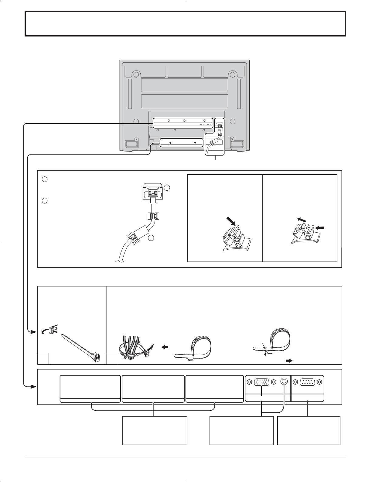
Conexiones
– Fijación del cable de alimentación de CA
Conecte el enchufe en
1
el tomacorriente del
cuerpo principal.
2
Fije la abrazadera.
2
– Bandas de fijación de cables
Asegure cualquier exceso de los cables con las bandas según sea necesario.
Pase la banda de fijación
de cables suministrada a
través de la presilla como
se muestra en la figura.
Para asegurar los cables conectados a los terminales, ponga la banda de fijación de
cables alrededor de los cables y luego pase el extremo de la banda que forma la punta
a través del bloque de cierre, como se muestra en la figura.
Asegurándose de que los cables estén lo suficientemente flojos como para
reducir al mínimo la tensión (especialmente el cable de la alimentación), una
firmemente todos los cables con la banda de fijación suministrada.
Conexión del cable de alimentación de CA (vea la página 12)
1
Para apretar: Para aflojar:
Tire
Cómo fijar:
Fije empujando hacia
adentro hasta que oiga
un ruido seco.
Empuje la perilla
Cómo soltar:
Suelte moviendo hacia
arriba mientras tira del
resalto.
1
SLOT1 SLOT2 SLOT3
2
Ranuras de inserción
de tableros de
terminales opcionales
(tapadas)
Del terminal de salida
del monitor de una
computadora
(vea la página 10)
Tire
AUDIO
SERIALPC IN
Del terminal serial de
una computadora
(vea la página 11)
9
Page 54
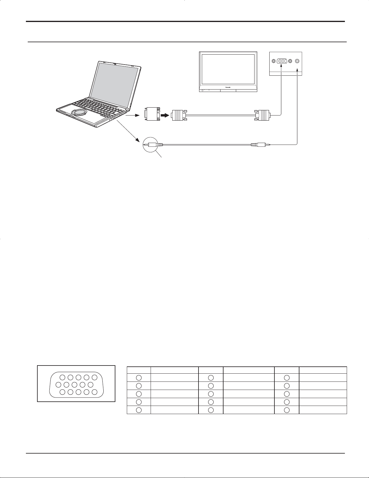
Conexiones
Conexión de los terminales de entrada PC
Ordenador
Adaptador de conversión
(si fuera necesario)
RGB
Cable PC
mini D sub
15 patillas
AUDIO
PC IN
Audio
Conecte un cable que coincida con el
terminal de salida de audio en la computadora.
Enchufe estéreo
Notas:
• Debido a la falta de espacio, a veces usted puede tener problemas al conectar el cable mini D-sub 15P con núcleo de
ferrita a un terminal de entrada de PC.
• Las señales de ordenador que pueden entrar son las que tienen una frecuencia de exploración horizontal de 15 a 110
kHz y una frecuencia de exploración vertical de 48 a 120 Hz. (Sin embargo, las señales que exceden 1.200 líneas no
se visualizarán correctamente.)
• La resolución del visor tiene un máximo de 640 × 480 puntos (TH-37PG9U, TH-42PG9U), 768 × 720 puntos (TH-37PR9U),
768 × 768 puntos (TH-42PR9U) cuando el modo de aspecto se ajusta en “4:3”, y de 852 × 480 puntos (TH-37PG9U,
TH-42PG9U), 1.024 × 720 puntos (TH-37PR9U), 1.024 × 768 puntos (TH-42PR9U) cuando el modo de aspecto se
ajusta en “16:9”. Si la resolución del visor excede estos máximos, tal vez no sea posible mostrar los detalles finos con
suficiente claridad.
• Los terminales de entrada PC son compatibles con DDC1/2B. Si que se conecta no es compatible con DDC1/2B,
necesitará hacer los cambios de ajuste en el momento de la conexión.
• Algunos modelos de PC no pueden conectarse a la pantalla de plasma.
• No es necesario un adaptador para con terminal mini D sub 15 patillas compatibles con DOS/V.
• Esta figura es sólo a modo de ejemplo.
• Los equipos y cables adicionales de la figura no se suministran con este equipo.
• No ajuste las frecuencias de exploración horizontal y vertical para las señales de PC a niveles que están por encima o
por debajo de la gama de frecuencias especificada.
• La entrada de componente es posible con las patillas 1, 2 y 3 del conector D sub de 15 patillas.
Nombres de las señales del conector mini D sub 15 patillas
N° patilla Nombre de la señal N° patilla Nombre de la señal N° patilla Nombre de la señal
1514131211
67839
1
2
10
45
Forma de las patillas para
el terminal de entrada
1
2
3
4
5
R (rojo)
G (verde)
B (azul)
NC (no conectado)
GND (tierra)
PC
10
6
7
8
9
10
GND (tierra)
GND (tierra)
GND (tierra)
NC (no conectado)
GND (tierra)
11
12
13
14
15
NC (no conectado)
SDA
HD/SYNC
VD
SCL
Page 55

Conexiones
Conexión de los terminales SERIAL
El terminal SERIAL se utiliza cuando la pantalla de plasma se controla mediante una ordenador.
Ordenador
9876
Cable recto
RS-232C
SERIAL
Forma de patillas del cable
de conversión RS-232C
D-SUB 9 patillas
Notas:
• Utilice el cable RS-232C para conectar el ordenador a la pantalla de plasma.
• Los ordenadores mostrados sólo sirven como ejemplo.
• El equipo y los cables adicionales mostrados no son suministrados con este aparato.
El terminal SERIAL cumple con la especificación de interface RS-232C para que pueda controlar la pantalla de plasma
mediante un ordenador conectado en este terminal.
El ordenador requiere el uso de un software que permita transmitir y recibir los datos de control que satisfagan las
condiciones que se dan a continuación. Utilice una aplicación de ordenador tal como un idioma de programación para
crear el software. Para más detalles, consulte la documentación de la aplicación de ordenador.
53214
Parámetros de comunicación
Nivel de señal
Método de sincronización
Velocidad de baudios
Paridad
Longitud de carácter
Bit de parada
Operaciones de control
Cumple con RS-232C
Asincrónico
9600 bps
Ninguna
8 bits
1 bit
-
Formato básico para datos de control
La transmisión de los datos de control del ordenador
empieza con la señal STX seguida por el comando, los
parámetros y por último una señal ETX en ese orden. Si
no hay parámetros, la señal de parámetro no necesita
ser transmitida.
STX C1 C2 C3 P1 P2 P3 P4: P5 ETX
Inicio
(02h)
Dos puntos
Comando de 3
caracteres (3 bytes)
Parámetro(s)
(1 - 5 bytes)
Fin
(03h)
Notas:
• Si se transmiten múltiples comandos, espere que
venga la respuesta para el primer comando, de la
unidad, antes de enviar el siguiente comando.
• Si se envía un comando incorrecto por error, esta
unidad enviará un comando “ER401” al ordenador.
Cable de conversión RS-232C
Hembra de 9 patillas D sub Detalles
R X D
T X D
GND
• No se usa
•
2
3
5
6
4
7
8
9
1
Cortocircuitado
NC
Comando
Comando
PON
POF
AVL
AMT
IMS
DAM
Parámetro
None
None
**
0
1
None
SL1
SL2
SL3
PC1
None
Detalles de control
Alimentación encendido
Alimentación apagado
Volume 00 - 63
Silenciamiento apagado
Silenciamiento encendido
Selección de entrada (conmutación)
Entrée Slot1
Entrée Slot2
Entrée Slot3
Entrée PC
Selección de modo de pantalla
(conmutación)
NORM
ZOOM
FULL
JUST
SELF
4 : 3
Zoom
16:9
Preciso
Panasonic Auto
Con la alimentación desconectada, esta pantalla sólo responde
al comando PON.
11
Page 56

Encendido/apagado de la alimentación
Conexión de la clavija del cable de alimentación de CA a la pantalla de plasma.
Fije firmemente la clavija del cable de alimentación
de CA en la pantalla de plasma con el fijador. (vea
la página 9)
Conexión de la clavija a una toma de corriente
Presione el interruptor principal de la pantalla de plasma para
encender el aparato.
Encendido de la alimentación: Verde
Ejemplo: La pantalla de abajo se mostrará durante un rato
después de encendida la pantalla de plasma. (La
condición del ajuste es un ejemplo.)
Presione la tecla de espera del mando a distancia para apagar la pantalla de plasma.
Panorámica de Plasma: Rojo (espera)
Presione la tecla de espera
plasma.
Panorámica de Plasma: Verde
del mando a distancia para encender la pantalla de
Sensor del mando
a distancia
POWER
Indicador de alimentación
12
Desconecte la alimentación de la pantalla de plasma presionando el interruptor
unidad si la pantalla de plasma está encendida o en modo de espera.
Nota:
Durante la operación de gestión de la alimentación, el indicador de la alimentación se pone
naranja en el estado de alimentación desconectada.
de la
Page 57

Selecciones iniciales
Selección de la señal de entrada
Seleccione las señales de entrada que van a ser conectadas instalando el tablero de terminales
opcional.
Presione para seleccionar la señal de entrada que va a
reproducirse desde el equipo que se ha conectado a la
pantalla de plasma.
Las señales de entrada cambiarán de la forma siguiente:
INPUT1 INPUT2 PC ININPUT3
Notas:
• También se puede seleccionar mediante la tecla INPUT de la unidad.
• El terminal de entrada no se seleccionará si la tarjeta de terminales no está instalada
en la SLOT(ranura).
• Seleccione de forma que las señales procedentes de la fuente conectada
concuerden con las de los terminales de entrada de vídeo componente/RGB. (vea
la página 32)
• En la visualización de pantalla 2 no se puede seleccionar el mismo modo de entrada
para la imagen principal y la imagen secundaria.
MENU
INPUT
VOL
ENTER/
Sujete la puerta en “PULL” y ábrala hacia arriba.
Selección del idioma del menú en pantalla
Presione para mostrar la pantalla “Configuración”.
Presione para seleccionar “Idioma de OSD”.
Presione para seleccionar su idioma preferido.
Idiomas seleccionables
English(UK)
Deutsch
Français
Italiano
Español
ENGLISH(US)
.......(Chino)
.......(Japonés)
Русский
.......(Ruso)
Configuración
Seleccione entrada componente/RGB
Etiqueta de entrada
Ahorro de consumo
Ahorro en reposo
Energía monitor
Autoapagado
Idioma de OSD Español
1/2
Señal
RGB
PC
Apagado
Apagado
Apagado
Apagado
13
Page 58

Controles básicos
Sensor de control remoto
POWER
INPUT
MENU
VOL
Tecla INPUT
(Selección del modo de INPUT1,
INPUT2, INPUT3 y PC IN )
(vea la página 13)
ENTER/
Piloto de encendido
Se enciende el piloto de funcionamiento.
• Desconectado El indicador está apagado (La unidad
consume algo de energía siempre
que el cable de alimentación se
mantiene conectado a la toma de
corriente.)
• Espera ..........Rojo
• Conectado .....Verde
• DPMS .............Naranja (Con señal de entrada
de PC y durante la operación del
protector de pantalla del PC.)
Interruptor principal
Ajuste de volumen
Subida “+” y bajada “-” del volumen Cuando se
visualice la pantalla del menú.
“+”: presione para mover el cursor hacia arriba.
“–”: presione para mover el cursor hacia abajo.
(vea la página 16)
Botón de introducción/aspecto
Este botón es trabado por el ajuste inicial. (vea
la página 16, 18)
Encendido/Apagado de la pantalla MENÚ
Este botón es trabado por el ajuste inicial.
Cada vez que se pulsa el botón MENU, la pantalla
de menú se conmuta. (vea la página 16)
Visión normal Imagen Configuración
Sonido Pos. /Tamaño
Tecla N (vea la página 19, 22, 23, 24)
Botón de Pos. /Tamaño (vea la página 19)
Tecla PICTURE (vea la página 22)
Tecla SURROUND
El ajuste del sonido ambiental se enciende y apaga
cada vez que se presiona la tecla SURROUND.
Los beneficios del sonido ambiental son enormes.
Usted puede ser rodeado completamente por el
sonido; como si estuviera en
una sala de conciertos o en un cine.
Nota:
El ajuste del sonido ambiental se memoriza por
separado para cada Modo de sonido. (Normal,
Dinámico, Borrar)
Encendido Apagado
Sonido ambiental
Encendido
14
Tecla INPUT
(Selección de INPUT1, INPUT2, INPUT3 y PC IN)
Pulse para seleccionar secuencialmente las ranuras de entrada
INPUT1, INPUT2, INPUT3 y PC IN. (vea la página 13)
Silenciamiento de sonido (vea la página 24)
Teclas numéricas (vea la página 37)
Tecla ASPECT
Presione para ajustar el aspecto. (vea la página 18)
Teclas multiventana (vea la página 20)
Page 59

Controles básicos
El mando a distancia no se incluye con este aparato. Puede adquirirlo separadamente.
Modelo : EUR7636070R
Tecla de espera (Encendido/Apagado)
La pantalla de plasma debe conectarse primero en el tomacorriente y con el interruptor principal (vea la página 12).
Pulse ON para encender la Pantalla de Plasma desde el modo de Espera. Pulse OFF para apagar la Pantalla de
Plasma al modo de Espera.
Teclas de posición
Tecla de ACTION
Presiónelo para seleccionar
y hacer ajustes.
Tecla SOUND
(vea la página 24)
Tecla R (vea la página 17)
Presione el botón R para volver a la pantalla de menú anterior.
Status button
Presione la tecla de estado para que aparezca el estado del sistema actual.
Etiqueta de entrada
1
PC
4:3
1
2
Modo de relación de ASPECT
2
(vea la página 18)
Apagado de temporizador
3
El indicador del temporizador
Temporizador 90
3
aparece sólo cuando se ha
seleccionado el temporizador.
Tecla SET UP (vea la página 16, 17)
Botones DIRECT INPUT
Pulse INPUT “1”, “2”, “3” o la tecla de selección de modo de entrada de
“PC” para seleccionar el modo de entrada de PC. Este botón se utiliza
para pasar directamente al modo INPUT.
Estos botones solamente pueden mostrar la ranura en que está instalada. Si
usted pulsa el botón cuya ranura no está instalada, aparece automáticamente
la señal de entrada actual.
Nota:
Puede producirse un efecto de imagen secundaria (retardo de la imagen)
en el panel de la pantalla de plasma cuando se mantiene una imagen fija en
el panel durante un período de tiempo prolongado. Se activa la función que
oscurece ligeramente la pantalla para evitar el efecto de imagen secundaria
(vea la página 39), aunque no es la solución perfecta para este efecto.
Ajuste del canal
Puede utilizar este botón cuando está instalada la tarjeta de sintonizador U/V con
MATE I/F (accesorios opcionales). Consulte las instrucciones de funcionamiento
de cada una de las tarjetas para conocer los detalles pertinentes.
Ajuste de volumen
Presione la tecla de volumen arriba “+” o abajo “–” para hacer subir o
bajar el nivel de volumen del sonido.
Tecla OFF TIMER
La pantalla de plasma puede programarse para cambiar al modo de
espera después de un intervalo predeterminado.El ajuste cambia a
30 minutos, 60 minutos, 90 minutos y
0 minutos (se cancela el temporizador)
cada vez que se presiona la tecla.
30 60
90
0
Cuando quedan tres minutos, destella “Temporizador 3”.
El temporizador queda cancelado cuando se produce un corte eléctrico.
Zoom digital (vea la página 25)
Pulse para tener
acceso al zoom
digital.
Esto muestra un aumento de la parte designada de la imagen visualizada.
15
Page 60

Indicación en pantalla
MENU
ENTER/
INPUT
VOL
Al menú de ajuste de
“Imagen” (vea la página 22)
1/2Imagen
Normalizar
Modo de Imagen
Contraste
Brillo
Color
Matiz
Nitidez
Temp. de color
Corrección de color
Ajuste avanzado
Normal
Normal
25
0
0
0
3
2/2Imagen
Normal
Apagado
Encendido
Presione para
seleccionar
“Encendido”.
Presione para
introducir “Ajuste
avanzado”.
A “Ajuste avanzado” bajo
el ajuste de imagen (vea la
página 22, 23)
Ajuste avanzado
Normalizar
Extensión negro
Nivel de entrada
W/B High R
W/B High B
W/B Low R
W/B Low B
Gamma
Auto ganancia
Normal
0
0
0
0
0
0
2.2
Apagado
También se puede pulsar el botón MENU
de la unidad.
Cada vez que se pulse el botón
MENU, la pantalla de menú cambiará.
Visión normal
Imagen
Configuración
Sonido Pos. /Tamaño
Pulse para
1
seleccionar.
[desde la unidad]
MENU
INPUT
VOL
1
1
Pulse para seleccionar.
2
Pulse para acceder a cada
ENTER/
2
pantalla de ajuste.
Configuración
Seleccione entrada componente/RGB
Etiqueta de entrada
Ahorro de consumo
Ahorro en reposo
Energía monitor
Autoapagado
Idioma de OSD Español
Señal
RGB
PC
Apagado
Apagado
Apagado
Apagado
1/2
A la pantalla “Pos. /Tamaño”
(vea la página 19)
Durante los de señal de entrada
“AV (Video S)”, “Componente” y
“DVI”.
Pos. /Tamaño
Normalizar
Normal
Pos. horizontal
Tamaño horizontal
Posición vertical
Tamaño vertical
0
0
0
0
Durante los de señal de entrada
“RGB/PC”.
Pos. /Tamaño
Normalizar
Normal
Pos. horizontal
Tamaño horizontal
Posición vertical
Tamaño vertical
Fase de reloj
0
0
0
0
0
16
A la pantalla de ajuste
“Sonido” (vea la página 24)
Sonido
Normalizar
Modo de sonido
Graves
Mid
Agudos
Balance
Sonido ambiental
Salida Audio (PIP)
Normal
Normal
0
0
0
0
Apagado
Principal
2/2Configuración
Protec. pantalla
MULTI DISPLAY
TEMPORIZADOR ajuste
Puesta de HORA ACTUAL
Page 61

Indicación en pantalla
2
Pulse para tener
A la pantalla “Señal” para “AV”
(S Vidéo (vea la página 32, 33)
[
Auto
4 : 3
AV
]
Señal
F. Y/C 3D (NTSC)
Sistema de color
Cinema reality
Panasonic Auto (4 : 3)
P-NR
Nota:
El menú de preparación “Señal” visualiza condiciones de ajuste diferentes para cada señal de entrada. (Vea la página 13)
Encendido
Apagado
Apagado
Para preparar Protec. pantalla
(vea las página 28-30)
Protec. pantalla
lnicio
función
Modo
Hora de inicio
Hora de finalización
Panel lateral
Autodesplazamiento
Límite de brillo
Protec. pantalla
lnicio
función
Modo
Tiempo periódico
Tiempo de operación
Panel lateral
Autodesplazamiento
Límite de brillo
HORA ACTUAL 99:99
De. barra blanca
Designación de tiempo
HORA ACTUAL 99:99
6:15
12:30
Alto
Apagado
Apagado
De. barra blanca
Intervalo
6:15
12:30
Alto
Apagado
Apagado
[desde la unidad]
acceso a cada
pantalla de
ajuste.
INPUT
MENU
Presione para volver a la siguiente pantalla de menú.
A la pantalla “Señal” para
“Componente” (vea la página 33)
Señal
Cinema reality
P-NR
[
Componente
Apagado
Apagado
A la pantalla “Señal” para
“RGB” (vea la página 33, 34)
]
Pulse para seleccionar Hora de inicio/Hora de finalización
(cuando se selecciona Designación de tiempo).
Pulse para seleccionar Tiempo periódico/Tiempo de operación
(cuando se selecciona Intervalo).
Presione para configurar.
Pulse el botón R para volver
al menú “Configuración”.
VOL
Señal
Sincro
Cinema reality
P-NR
Fre. H.
Fre. V.
ENTER/
33.8
60.0
Apagado
Apagado
kHz
Hz
Auto
[
RGB
Presione el botón R para
volver a la pantalla de menú
anterior.
A la pantalla “Señal” para “DVI”
(vea la página 33, 34)
]
Señal
Cinema reality
P-NR
Fre. H.
Fre. V.
Protec. pantalla
lnicio
función
Modo
Hora de inicio
Hora de finalización
Panel lateral
Autodesplazamiento
Límite de brillo
Protec. pantalla
lnicio
función
Modo
Tiempo periódico
Tiempo de operación
Panel lateral
Autodesplazamiento
Límite de brillo
HORA ACTUAL 99:99
De. barra blanca
Designación de tiempo
HORA ACTUAL 99:99
De. barra blanca
33.8
60.0
Intervalo
Apagado
Apagado
kHz
Hz
6:15
12:30
Apagado
Apagado
6:15
12:30
Apagado
Apagado
[
Alto
Alto
Digital
]
A la pantalla de selección TEMPORIZADOR
ajuste (vea la página 26, 27)
TEMPORIZADOR ajuste
Función de ENCENDIDO
Hora de ENCENDIDO
Función de APAGADO
Hora de APAGADO
HORA ACTUAL 99:99
Apagado
0:00
Apagado
0:00
Para Puesta de HORA ACTUAL
(vea la página 26)
Puesta de HORA ACTUAL
Ajustar
HORA ACTUAL
HORA ACTUAL 99:99
99:99
Pulse para seleccionar Hora de
ENCENDIDO/ Hora de APAGADO.
Presione para configurar la
Hora de Encendido/Hora
de Apagado.
Presione el botón R para volver
al menú “Configuración”.
TEMPORIZADOR ajuste
HORA ACTUAL 99:99
Función de ENCENDIDO
Hora de ENCENDIDO
Función de APAGADO
Hora de APAGADO
TEMPORIZADOR ajuste
HORA ACTUAL 99:99
Función de ENCENDIDO
Hora de ENCENDIDO
Función de APAGADO
Hora de APAGADO
Apagado
0:00
Apagado
0:00
Apagado
0:00
Apagado
0:00
17
Page 62

Controles de ASPECTO
La pantalla de plasma le permite disfrutar viendo la imagen en su tamaño máximo, incluyendo las imágenes en el formato
de cine.
Presione repetidamente para desplazarse por las opciones de
aspecto:
[desde la unidad]
El modo de aspecto cambia cada vez que se presiona la
INPUT
MENU
VOL
ENTER/
tecla ENTER.
[Durante las operaciones MULTI PIP]
• Una imagen al lado de la otra, imagen en imagen :
• Otras : No es posible conmutar el aspecto.
Notas:
• Para la entrada de señales PC, el modo cambia entre “4:3”, “Zoom” y “16:9” solamente.
• Para una entrada de señal de 1125 (1080) / 60i .50i. 24p. 25p. 30p. 24sF, 1250 (1 080) / 50i, 750 (720) / 60p. 50p , el
modo se ajusta en “16:9”, y no es posible cambiar.
• Panasonic Auto sólo puede seleccionarse durante la entrada de señal de vídeo.
•
El modo de aspecto se memoriza separadamente para cada terminal de entrada).
Modo Imagen Explicaciones
4
4:3
4:3
3
4 : 3 Zoom 16 : 9
Panasonic Auto Preciso
4 : 3 16 : 9
“4:3” mostrará una imagen 4:3 con un tamaño estándar 4:3.
Zoom
16:9
Preciso
Panasonic
Auto
4
4
4
416
Para una inagen
alargada
4
Para una imagen 4:3
16
Zoom
3
16
16:9
3
16
Preciso
3 9
El modo “Zoom” amplía la sección central de la imagen.
9
“16:9” mostrará la imagen con su tamaño máximo pero con cierto
alargamiento.
9
El modo “Preciso” mostrará una imagen 4:3 con su tamaño máximo,
pero con la corrección de aspecto aplicada al centro de la pantalla, por lo
que el alargue es sólo aparente en los bordes izquierdo y derecho de
la pantalla. El tamaño de la imagen dependerá de la señal original.
Panasonic Auto
39
La muestra de la imagen se ampliará automá-ticamente (dependiendo
de la fuente de imagen). Permitiéndole ver la imagen con su máximo
tamaño.
Notas:
•
Imagen expandida
El modo “Panasonic Auto” ha sido diseñado para ajustar automáticamente
la relación de aspecto y poder manipular una variedad de programas
de 16:9 y 4:3. Ciertos programas de 4:3 como, por ejemplo, los datos
Cambia de acuerdo
al ajuste del modo
Panasonic
3
automático (vea la
página 33).
del mercado de valores, pueden hacer que el tamaño de la pantalla
cambie algunas veces de forma inesperada. Cuando vea tales p
rogramas, se recomienda ajustar el ASPECTO a 4:3.
• Si ajusta la posición vertical y el tamaño vertical de la imagen en
Panasonic Auto en modo 16:9, el ajuste no se memorizará. Al salir
del modo, la pantalla volverá al ajuste anterior.
• Mientras esté instalada la TY-FB9BD (tarjeta de terminales de vídeo
dual BNC opcional) no se podrá seleccionar Panasonic AUTO.
Nota: No deje que el modo 4:3 se muestre durante largos periodos de tiempo, porque esto puede dejar una imagen
fantasma permanente en la pantalla de plasma.
18
Page 63

Ajuste de Pos. /Tamaño
1
Pulse para visualizar el menú Pos. /Tamaño.
2
Presione para seleccionar “Pos. horizontal/Tamaño
horizontal/ Posición vertical/Tamaño vertical/Fase
de reloj”.
Presione para ajustar la Pos. /Tamaño.
3
4
Notas:
• Los detalles de los ajustes se memorizan por separado para los diferentes formatos
de señal de entrada. (Los ajustes para las señales componentes se memorizan
para cada 525 (480) / 60i · 60p, 625 (575) / 50i · 50p, 1125 (1080) / 60i · 50i · 24p
· 25p · 30p · 24sF, 1250 (1080) / 50i, 750 (720) / 60p · 50p, y las señales RGB/
PC/DVI se memorizan para cada frecuencia.)
• Si se recibe una señal de “Localización progresiva” o “Localización regresiva”
de una videograbadora o de un reproductor DVD, la posición de la imagen se
desplazará hacia arriba o hacia abajo. Este movimiento de posición de la imagen
puede controlarse con la función “Pos. /Tamaño”.
• Si ajusta la posición vertical y el tamaño vertical de la imagen en Panasonic Auto
en modo 16:9, el ajuste no se memorizará. Al salir del modo, la pantalla volverá
al ajuste anterior.
Presione para salir del modo de ajuste.
Durante los de señal de entrada “AV
(Video S)”, “Componente” y “DVI”.
Pos. /Tamaño
Normalizar
Pos. horizontal
Tamaño horizontal
Posición vertical
Tamaño vertical
Durante los de señal de entrada
“RGB/PC”.
Pos. /Tamaño
Normalizar
Pos. horizontal
Tamaño horizontal
Posición vertical
Tamaño vertical
Fase de reloj
Normal
0
0
0
0
Normal
0
0
0
0
0
Pos.
horizontal
Posición
vertical Ajusta la posición vertical.
Fase de reloj
(Modo RGB/PC)
Consejos útiles ( /
Mientras la visualización Pos. /Tamaño está activada, si se presiona el botón N del mando a distancia en cualquier
momento o el botón de ACTION( ) durante “Normalizar”, todos los valores de los ajustes volverán a los ajustes hechos
en fábrica.
Ajusta la posición horizontal.
Elimina el parpadeo y la distorsión.
Normalizar
Normalización)
Tamaño
horizontal
Tamaño
vertical Ajusta el tamaño vertical.
Ajusta el tamaño horizontal.
19
Page 64
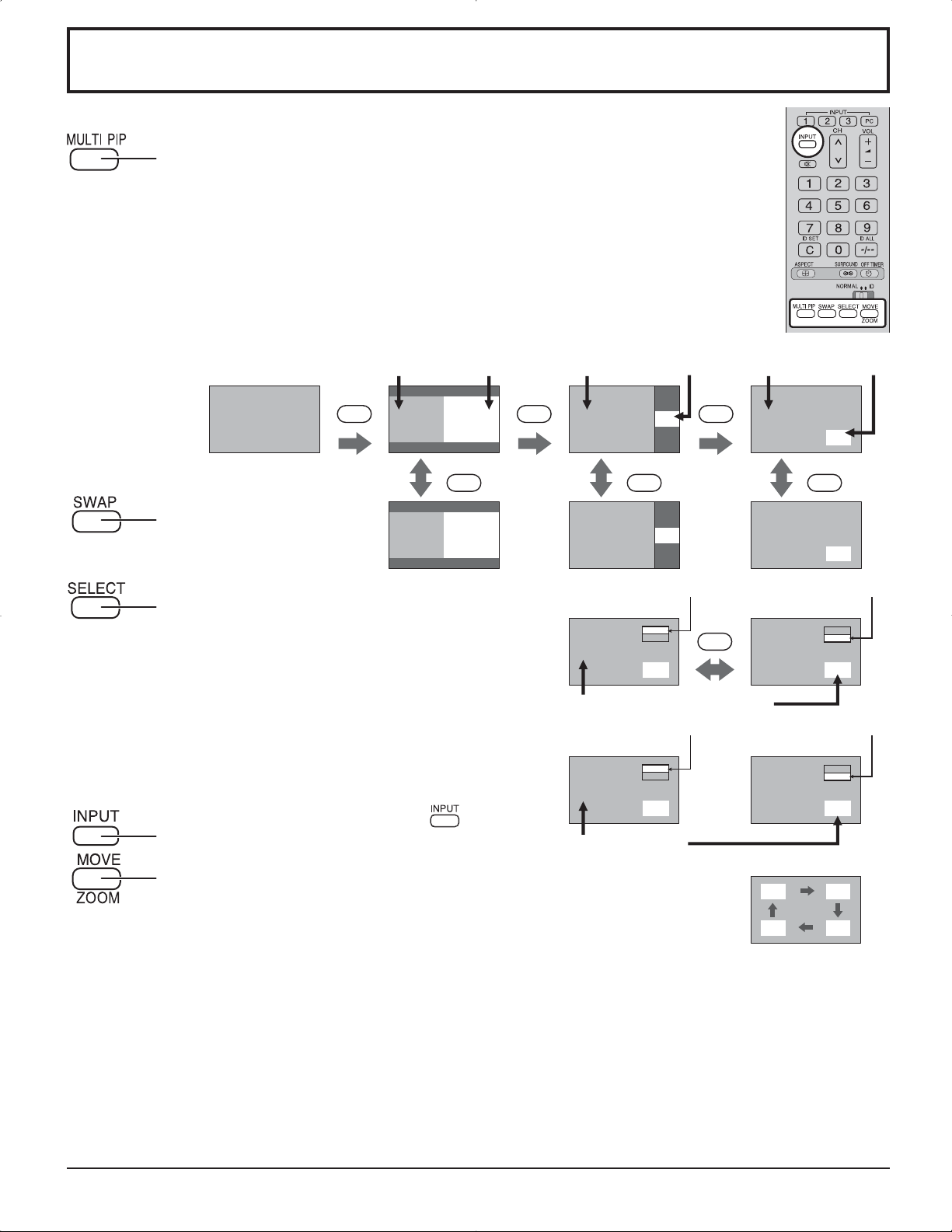
MULTI PIP
Presione repetidamente.
Cada vez que se presiona este botón, la imagen principal y la imagen
secundaria se visualizan como se muestra a continuación.
[Una imagen al lado de la otra] [Imagen en imagen]
Imagen principal Imagen secundaria
MULTI
PIP
Visión normal
Presione para cambiar la
imagen principal por la imagen
secundaria.
Presione para seleccionar el modo de entrada. Bajo
la visualización de la imagen principal y la imagen
secundaria, seleccione la imagen cuya señal de
entrada quiere cambiar.
Notas:
• El sonido de la imagen secundaria se oye mientras
se realiza una operación con imagen secundaria.
• La operación con imagen secundaria vuelve
automáticamente a la operación con imagen
principal si no se ha llevado a cabo una operación
con imagen secundaria durante unos 3 segundos
o si se presiona uno cualquiera de los botones del
mando a distancia (excepto el botón
Pulse para cambiar la señal de entrada
AB
SWAP SWAP SWAP
BA
[Ejemplo]
).
[Imagen fuera de imagen]
Imagen principal Imagen secundaria Imagen principal Imagen secundaria
MULTI
PIP
A
MULTI
PIP
B
A
B
B
A
B
A
Brilla la etiqueta de la imagen principal Brilla la etiqueta de la imagen secundaria
PC1
VIDEO2
A
B
Es posible conmutar los modos de entrada
Cambia la etiqueta de la imagen principal Cambia la etiqueta de la imagen secundaria
VIDEO2
VIDEO1
C
B
Cambia la imagen
SELECT
A
A
PC1
VIDEO2
B
PC1
VIDEO2
D
Presione para mover la imagen secundaria.
Cada vez que se presione, la ubicación de la imagen secundaria cambiará.
Notas:
• Esto botón sólo sirve para el modo de imagen en imagen.
• La imagen secundaria puede estar tapada por la visualización de la pantalla
Notas:
• La salida de sonido proviene de la imagen seleccionada en Salida Audio (PIP) (Vea la página 24).
•
En la visualización de pantalla 2 se puede seleccionar el mismo modo de entrada para la imagen principal y la imagen secundaria.
• La imagen principal y la imagen secundaria se procesan mediante circuitos distintos, lo cual produce una ligera diferencia
en la nitidez de las imágenes. También puede producirse una diferencia en la calidad de la imagen secundaria en función
del tipo de señales que se muestran en la imagen principal y del modo de visualización de 2 imágenes.
• Dado el tamaño pequeño de las sub-imágenes, éstas no pueden mostrarse en detalle.
• La imagen de pantalla del ordenador aparece en un formato simplificado y tal vez no sea posible discernir sus detalles
en forma satisfactoria.
•
Las siguientes combinaciones de dos señales análogas no pueden visualizarse simultáneamente :
Componente - PC (RGB), PC (RGB) - Componente, PC (RGB) - PC (RGB)
dependiendo de su posición.
Componente - Componente,
20
Page 65
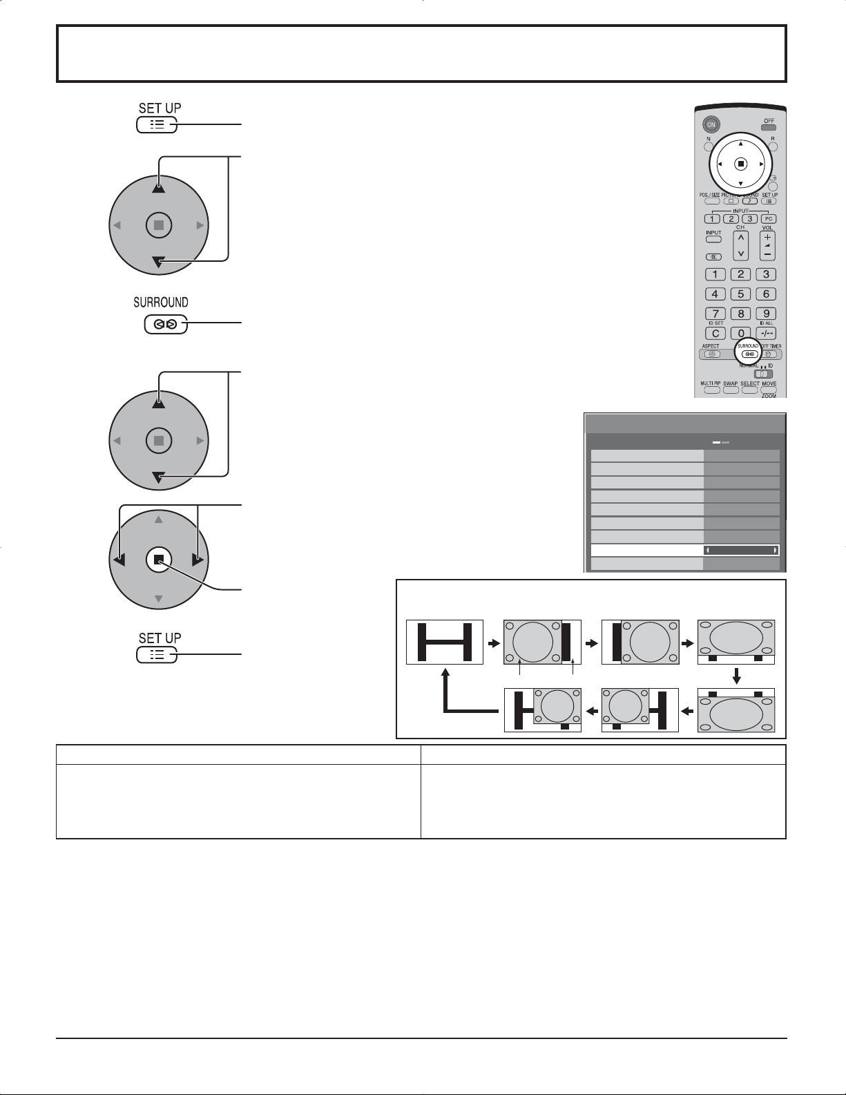
Advanced PIP (PIP avanzado)
1
2
3
4
5
Pulse para visualizar el menú Setup.
Pulse para seleccionar “Idioma de OSD”
Mantenga presionado el botón hasta visualizar el menú Options
(Opciones).
Pulse para seleccionar Advanced PIP (PIP avanzado).
Options
Off-timer function
Onscreen display
Initial INPUT
Pulse para ajustar el menú.
Off (Apagado): Configura el modo normal del visor
de dos pantallas (ver página 20).
On (Encendido): Configura el modo Advanced PIP.
Initial VOL level
Maximum VOL level
INPUT lock
Studio W/B
Advanced PIP
Display size
Enable
Off
Off
1/3
On
Off
0
0
Off
Off
Off
Off
Pulse para confirmar.
6
Notas:
• Señal correspondiente a Advanced PIP
Sub-pantalla Pantalla principal
NTSC, PAL, SECAM (sintonizador, video)
525i, 525p, 625i, 625p, 750/60p, 750/50p, 1125/60i,
1125/50i, 1250/50i (Video de componente, RGB, DVI,
SDI, HDMI)
• La salida de sonido proviene de la imagen seleccionada en Salida Audio (PIP). (ver página 24).
• En la visualización de pantalla 2 se puede seleccionar el mismo modo de entrada para la imagen principal y la imagen
secundaria.
• La imagen principal y la imagen secundaria se procesan mediante circuitos distintos, lo cual produce una ligera diferencia
en la nitidez de las imágenes. También puede producirse una diferencia en la calidad de la imagen secundaria en función
del tipo de señales que se muestran en la imagen principal y del modo de visualización de 2 imágenes.
• Dado el tamaño pequeño de las sub-imágenes, éstas no pueden mostrarse en detalle.
• La imagen de pantalla del ordenador aparece en un formato simplificado y tal vez no sea posible discernir sus detalles
en forma satisfactoria.
•
Las siguientes combinaciones de dos señales análogas no pueden visualizarse simultáneamente
Componente - Componente, Componente - PC (RGB), PC (RGB) - Componente, PC (RGB) - PC (RGB)
•
Consulte el manual de operaciones de cada tablero para conocer las señales correspondientes para DVI, SDI y HDMI.
Pulse para salir
del menú Options
(Opciones).
Una pantalla Advanced PIP
(PIP avanzado)
Sub-pantalla Pantalla principal
640 x 480@60Hz, 852 x 480@60Hz, 1024 x 768@60Hz,
1366 x 768@60Hz (RGB, DVI, HDMI)
1280 x 768@60Hz (DVI)
:
21
Page 66
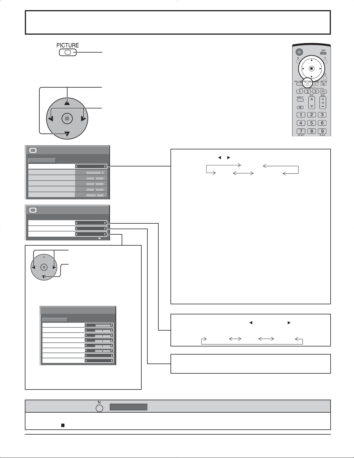
Ajuste de imagen
1
Presione la tecla PICTURE del mando a distancia para
mostrar la pantalla de menú “Imagen”.
Seleccione para ajustar cada elemento.
2
Presione para seleccionar el menú para ajustar.
Seleccione el nivel deseado mirando a la imagen de
detrás del menú.
Imagen
Normalizar
Modo de Imagen
Contraste
Brillo
Color
Matiz
Nitidez
Temp. de color
Corrección de color
Ajuste avanzado
Normal
25
0
0
0
3
1/2
Normal
2/2Imagen
Normal
Apagado
Encendido
Presione la tecla o para cambiar entre los modos.
Normal
Cine Dinámico
Normal
Para ver en ambientes estándar (iluminación de la
tarde). Este menú selecciona los niveles normales del
Brillo y del Contraste.
Dinámico
Para ver en ambientes brillantes. Este menú selecciona
niveles de Brillo y Contraste más altos que los normales.
Presione para seleccionar
“Encendido”.
Presione para introducir
“Ajuste avanzado”.
Ajuste avanzado Encendido
Permite realizar ajustes finos de la imagen con
un nivel profesional (vea la página siguiente).
Ajuste avanzado
Normalizar
Extensión negro
Nivel de entrada
W/B High R
W/B High B
W/B Low R
W/B Low B
Gamma
Auto ganancia
Normal
0
0
0
0
0
0
2.2
Apagado
Ajuste avanzado Apagado
Visualiza imágenes con ajustes del menú
Imagen.
Consejos útiles ( /
Normalizar
Cine
Ideal para ver películas.
Nota:
Si quiere cambiar la imagen y el color del menú “Imagen”
seleccionado por otra cosa, haga el ajuste utilizando el
menú “Imagen” recomendado en el menú (vea la página
siguiente).
Presione la tecla de izquierda o de derecha para cambiar
entre los modos.
Normal Frío Cálido
Corrección de color Encendido
Permite el ajuste de colores vivos de forma automática.
Normalización)
Mientras se visualiza el menú “Imagen”, si se presiona el botón N del mando a distancia en cualquier momento o el botón
de ACTION ( ) durante “Normalizar”, todos los valores de los ajustes volverán a los ajustes hechos en fábrica.
22
Page 67

Ajuste de imagen
Elemento Efecto Ajustes
Contraste
Brillo
Color
Matiz
Nitidez
Menos Más
Más oscuro
Menos Más
Rojizo Verdoso
Menos Más
Más brillante
Selecciona el brillo y la densidad
apropiados para la sala.
Ajuste para ver fácilmente imágenes
oscuras como, por ejemplo, escenas
nocturnas o cabello negro.
Ajuste para un color más ligero.
Ajuste para un color de piel más
lindo.
Muestra una imagen nítida.
Notas:
• Los ajustes de “Color” y “Matiz” no se
• Usted podrá cambiar el nivel de cada
• Los detalles de ajuste para “Normal”,
• El ajuste “Matiz” se puede ajustar para la
• El cambio es muy pequeño cuando se
Ajustes avanzados
Elemento Efecto Detalles
Extensión
negro
Menos Más
Ajusta las sombras oscuras de la imagen en gradación.
pueden ajustar para las señales de
entrada “RGB/PC” y “DVI”.
función (Contraste, Brillo, Color, Matiz,
Nitidez) en cada menú Imagen.
“Dinámico” y “Cine” respectivamente se
memorizan por separado para cada modo
de terminal de entrada.
señal NTSC solamente durante la señal
de entrada “AV(Video S)”.
aumenta “Contraste” con una imagen
brillante o se reduce con una imagen
oscura.
Nivel de
entrada
W/B High R
W/B High B
W/B Low R
W/B Low B
Gamma
Auto
ganancia
Notas:
• Realice el ajuste “W/B” de la forma siguiente.
1. Ajuste el equilibrio del blanco de las secciones brillantes, utilizando los ajustes “W/B High R” y “W/B High B”.
2. Ajuste el equilibrio del blanco de las secciones oscuras, utilizando los ajustes “W/B Low R” y “W/B Low B”.
3. Repita los pasos 1 y 2.
Los pasos 1 y 2 afectan a los ajustes del otro, así que repita cada uno de los pasos para hacer el ajuste.
• Los valores de los ajustes se memorizan por separado para cada modo de terminal de entrada.
• Los valores de la gama de ajuste deberán utilizarse como una referencia para el ajuste.
Menos Más
Menos Más
Menos Más
Menos Más
Menos Más
Abajo Arriba
Abajo Arriba
Ajusta las partes que están sumamente brillantes y son difíciles de ver.
(Esto no se puede ajustar cuando la señal de entrada es DVI.)
Ajusta el equilibrio del blanco para las zonas color rojo claro.
Ajusta el equilibrio del blanco para las zonas color azul claro.
Ajusta el equilibrio del blanco para las zonas color rojo oscuro.
Ajusta el equilibrio del blanco para las zonas color azul oscuro.
Curva “S” 2.0 2.2 2.5
Aumenta automáticamente el brillo de la señal oscura.
Consejos útiles ( /
En el mando a distancia, mientras mientras se indica el menú “Ajuste avanzado”, si se presiona la tecla N en cualquier
momento o tecla de ACTION ( ) durante “Normalizar”, todos los valores de ajuste volverán a los ajustes de fábrica.
Normalizar
Normalización)
23
Page 68

Ajuste del sonido
1
Pulse para mostrar el menú Sonido.
Seleccione para ajustar cada elemento.
2
Presione para seleccionar el menú para ajustar.
Seleccione el nivel deseado escuchando el sonido.
Graves
Ajusta los sonidos bajos
Mid
Ajusta el sonido normal
Agudos
Ajusta los sonidos altos
Balance
Sonido
Normalizar
Modo de sonido
Graves
Mid
Agudos
Balance
Sonido ambiental
Salida Audio (PIP)
Normal
Normal
0
0
0
0
Apagado
Principal
Normal
Dinámico
Borrar
Emite el sonido original.
Acentúa el sonido agudo.
Atenúa la voz humana.
Ajusta los volúmenes de los
canales izquierdo y derecho
Sonido ambiental
Seleccione Encendido o Apagado
Principal
Sub
Selecciona el
sonido de la
imagen principal.
Seleccionar sonido
de cuadro PIP.
A
INPUT1
PC
B
INPUT1
PC
(Cuando se elige el
sonido de la imagen
principal.)
(Cuando se elige el
sonido de cuadro PIP.)
A
B
Aparece la nota musical a la derecha de la etiqueta de la pantalla de salida
de audio.
Notas:
•
Presione la tecla Sonido ambiental para encender y apagar directamente el efecto de sonido ambiental. (vea la página 14)
• Los ajustes de Graves, Mid, Agudos y Sonido ambiental se memorizan separadamente para cada modo de sonido.
Consejos útiles ( /
Normalizar
Normalización)
Mientras se visualiza el menú “Sonido”, si se presiona el botón N del mando a distancia en cualquier momento o el
botón de ACTION( ) durante “Normalizar”, todos los valores de los ajustes volverán a los ajustes hechos en fábrica.
Silenciamiento
Esto resulta muy útil cuando se contesta el teléfono o se reciben visitantes inesperados.
Presione esta tecla para silenciar el sonido.
Presiónela de nuevo para reactivar el sonido. El sonido se reactiva también cuando se
apaga la alimentación o se cambia el nivel del sonido.
24
Page 69
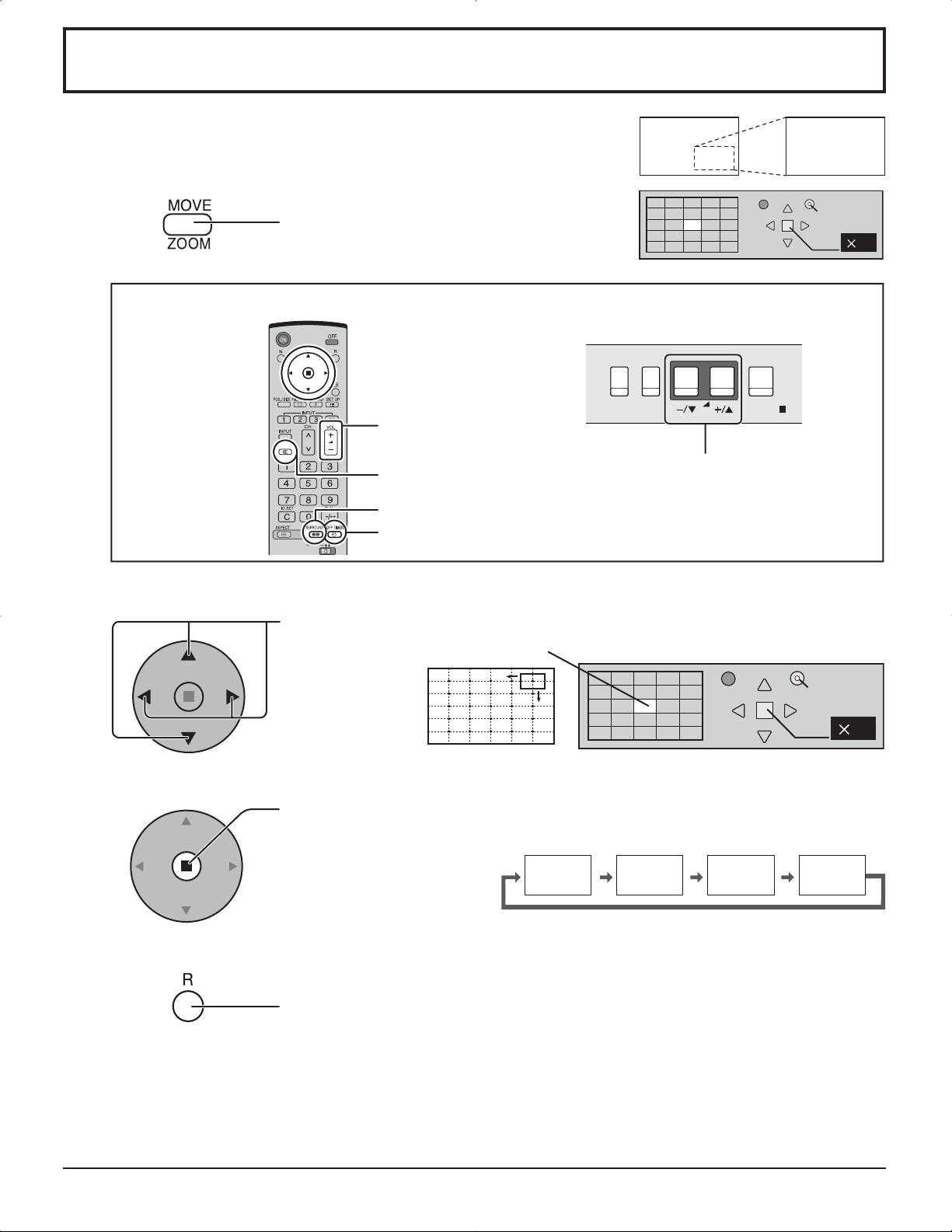
Zoom digital
Esto muestra una parte designada de la imagen visualizada que ha sido
aumentada.
1
2
Visualice la “Operation Guide”.
Pulse para tener acceso al zoom digital.
Se visualizará la “Operation Guide”.
Durante el empleo del zoom digital sólo se podrán utilizar los botones siguientes.
[Transmisor]
Botón VOL
Botón MUTE
Botón SURROUND
Botón OFF TIMER
Seleccione el área de la imagen que va a ampliar.
[Unidad]
INPUT
MENU
Botón VOL
VOL
Salir
1
ENTER/
Presione sobre la parte que va a ampliar para seleccionarla.
El cursor se moverá.
Salir
21
3
4
Notas:
• Cuando se desconecte la alimentación (incluyendo la operación “Temporizador”), la función del zoom digital se
• La función del zoom digital no se podrá seleccionar en los estados de operación siguientes:
Operación “Multi-viewer” (Imagen en imagen, Imagen fuera de imagen, Una imagen al lado de la otra). (vea la página
• Mientras está funcionando el zoom digital, “Ajuste de Pos./Tamaño” no se pueden utilizar.
Seleccione el aumento requerido para la visualización ampliada.
Cada vez que se presione este botón, el factor de aumento cambiará.
Esto se muestra en la imagen que está siendo visualizada.
× 1 × 2 × 3 × 4
Retorno a la visualización normal (salida del modo del zoom digital).
Púlselo para salir del modo del zoom digital.
desactivará.
20)
25
Page 70

Puesta de HORA ACTUAL / TEMPORIZADOR ajuste
El temporizador puede encender o apagar la pantalla de plasma.
Antes de intentar ajustar el temporizador, confirme HORA ACTUAL y haga el ajuste necesario.
Luego ajuste el Hora de ENCENDIDO / Hora de APAGADO.
1
2
Pulse para visualizar la pantalla de menú
Configuración.
Presione para seleccionar
TEMPORIZADOR ajuste o Puesta
de HORA ACTUAL.
Presione para visualizar la pantalla TEMPORIZADOR
ajuste o la pantalla Puesta de HORA ACTUAL.
Puesta de HORA ACTUAL
Visualice la pantalla Puesta de HORA ACTUAL.
Configuración
Señal
Seleccione entrada componente/RGB
Etiqueta de entrada
Ahorro de consumo
Ahorro en reposo
Energía monitor
Autoapagado
Idioma de OSD Español
Protec. pantalla
MULTI DISPLAY
TEMPORIZADOR ajuste
Puesta de HORA ACTUAL
1/2
RGB
PC
Apagado
Apagado
Apagado
Apagado
2/2Configuración
Para ajustar HORA ACTUAL, siga el procedimiento descrito a continuación.
1
2
3
Pulse para seleccionar HORA ACTUAL.
Presione para poner la HORA ACTUAL.
botón: Avance
botón: Retroceso
Notas:
• Al presionar una vez el botón “ ” o “ ” , la HORA ACTUAL cambia en pasos de 1
minuto.
• Al presionar continuamente el botón “ ” o “ ”, la HORA ACTUAL cambia en pasos de 15
minutos.
Presione para seleccionar Ajustar.
Pulse para completar el ajuste HORA ACTUAL.
Nota:
No se puede seleccionar Ajustar a menos que la HORA ACTUAL esté puesta.
Presione para salir de Puesta de HORA ACTUAL.
Puesta de HORA ACTUAL
HORA ACTUAL 99:99
Ajustar
HORA ACTUAL
Puesta de HORA ACTUAL
HORA ACTUAL 99:99
Ajustar
HORA ACTUAL
99:99
99:99
26
Page 71

Puesta de HORA ACTUAL / TEMPORIZADOR ajuste
TEMPORIZADOR ajuste
Visualice la pantalla TEMPORIZADOR ajuste.
1
2
Pulse para seleccionar
Hora de ENCENDIDO/ Hora de APAGADO.
Presione para configurar la Hora de ENCENDIDO/
Hora de APAGADO.
botón: Avance
botón: Retroceso
Notas:
• Al presionar una vez el botón “ ” o “ ” la Hora de ENCENDIDO/Hora de APAGADO
cambia en pasos de 1 minuto.
• Al presionar continuamente el botón “ ” o “ ”la Hora de ENCENDIDO/Hora de
APAGADO cambia en pasos de 15 minutos.
Pulse para seleccionar Función de
ENCENDIDO/Función de APAGADO.
Pulse para seleccionar ENCENDIDO.
TEMPORIZADOR ajuste
HORA ACTUAL 99:99
Función de ENCENDIDO
Hora de ENCENDIDO
Función de APAGADO
Hora de APAGADO
TEMPORIZADOR ajuste
HORA ACTUAL 99:99
Función de ENCENDIDO
Hora de ENCENDIDO
Función de APAGADO
Hora de APAGADO
Apagado
0:00
Apagado
0:00
Apagado
0:00
Apagado
0:00
3
Nota:
La función del temporizador no se activará si no se establece “HORA ACTUAL”.
Pulse dos veces para salir de Configuración.
27
Page 72

Protec. pantalla (Para impedir las imágenes secundarias)
No visualice una imagen fija, especialmente en el modo 4:3, para cualquier longitud del tiempo.
Si la pantalla tiene que estar encendida deberá utilizarse Protec. pantalla.
2/2Configuración
1
2
Pulse para visualizar la pantalla de menú Configuración.
Pulse para seleccionar Protec. pantalla.
Pulse para seleccionar la pantalla Protec. pantalla.
Protec. pantalla
MULTI DISPLAY
TEMPORIZADOR ajuste
Puesta de HORA ACTUAL
Selección de Inversión/desplazamiento
3
Pulse para seleccionar función.
Pulse para seleccionar la función deseada.
De. barra blanca Inversión de imagen
De. barra blanca : La barra blanca se desplazará de izquierda a derecha.
Inversión de imagen : En la pantalla se mostrará una imagen negativa.
Selección del modo de operación
4
Pulse para seleccionar Modo.
Pulse para seleccionar cada elemento del modo.
Apagado
Intervalo : Funciona cuando Tiempo periódico y Tiempo de operación
Designación de tiempo : Funciona cuando Hora de inicio y Hora de finalización están
Encendido :
Protec. pantalla
lnicio
función
Modo
Hora de inicio
Hora de finalización
Panel lateral
Autodesplazamiento
Límite de brillo
Protec. pantalla
lnicio
función
Modo
Hora de inicio
Hora de finalización
Panel lateral
Autodesplazamiento
Límite de brillo
HORA ACTUAL 99:99
De. barra blanca
Apagado
6:15
12:30
Alto
Apagado
Apagado
HORA ACTUAL 99:99
De. barra blanca
Apagado
6:15
12:30
Alto
Apagado
Apagado
están establecidos y llegan esas horas.
establecidas y llegan esas horas.
Funciona cuando se selecciona inicio y se presiona ACTION ( ).
Ajuste de Inicio
5
28
Protec. pantalla
Cuando Modo esté en Encendido, presione para
seleccionar Inicio.
lnicio
función
Modo
Hora de inicio
Hora de finalización
Panel lateral
Autodesplazamiento
Límite de brillo
HORA ACTUAL 99:99
De. barra blanca
Encendido
6:15
12:30
Alto
Apagado
Apagado
Presione para iniciar el Protec. pantalla.
La pantalla de menú desaparecerá y se activará el Protec. pantalla. Para detener el
Protec. pantalla, pulse el botón R.
Page 73
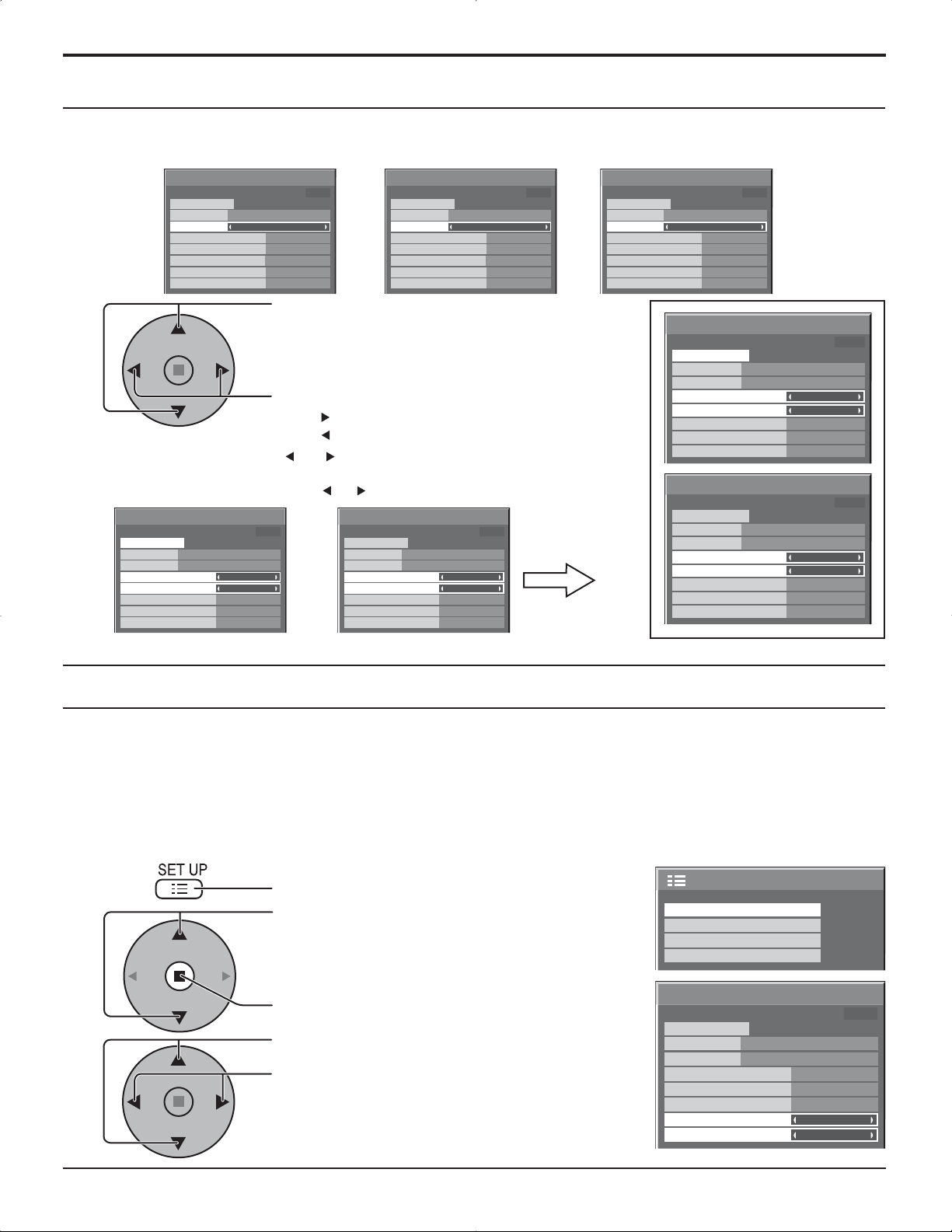
Protec. pantalla (Para impedir las imágenes secundarias)
Establecimiento del tiempo de activación de Protec. Pantalla
Después de seleccionar Designación de tiempo o Intervalo, el TEMPORIZADOR ajuste pertinente quedará disponible para la selección
y podrá establecerse Operating Time. (El tiempo no se puede establecer cuando “Modo” está en “Encendido” o en “Apagado”.)
Protec. pantalla
lnicio
función
Modo
Hora de inicio
Hora de finalización
Panel lateral
Autodesplazamiento
Límite de brillo
HORA ACTUAL 99:99
De. barra blanca
Designación de tiempo
6:15
12:30
Alto
Apagado
Apagado
Pulse para seleccionar Hora de inicio/Hora de
finalización (cuando se selecciona Designación de tiempo).
Pulse para seleccionar Tiempo periódico/Tiempo de
operación (cuando se selecciona Intervalo).
Presione para configurar.
botón : Avance
Notas:
botón : Retroceso
• Al presionar una vez el botón “ ” or “ ”, la hora cambia en pasos de 1 minuto.
[Sin embargo, la conmutación se produce cada 15 minutos cuando se selecciona Periodic Time.]
• Al presionar continuamente el botón “ ” o “ ”, la hora cambia en pasos de 15 minutos.
Protec. pantalla
lnicio
función
Modo
Hora de inicio
Hora de finalización
Panel lateral
Autodesplazamiento
Límite de brillo
HORA ACTUAL 99:99
De. barra blanca
Designación de tiempo
0:00
0:00
Alto
Apagado
Apagado
Protec. pantalla
Protec. pantalla
lnicio
función
Modo
Tiempo periódico
Tiempo de operación
Panel lateral
Autodesplazamiento
Límite de brillo
lnicio
función
Modo
Tiempo periódico
Tiempo de operación
Panel lateral
Autodesplazamiento
Límite de brillo
HORA ACTUAL 99:99
HORA ACTUAL 99:99
De. barra blanca
De. barra blanca
Intervalo
0:00
0:00
Alto
Apagado
Apagado
Intervalo
Apagado
Apagado
6:15
12:30
Alto
Protec. pantalla
lnicio
función
Modo
Hora de inicio
Hora de finalización
Panel lateral
Autodesplazamiento
Límite de brillo
HORA ACTUAL 99:99
De. barra blanca
Apagado
6:15
12:30
Alto
Apagado
Apagado
Protec. pantalla
lnicio
función
Modo
Hora de inicio
Hora de finalización
Panel lateral
Autodesplazamiento
Límite de brillo
Protec. pantalla
lnicio
función
Modo
Tiempo periódico
Tiempo de operación
Panel lateral
Autodesplazamiento
Límite de brillo
HORA ACTUAL 99:99
De. barra blanca
Designación de tiempo
6:15
12:30
Alto
Apagado
Apagado
HORA ACTUAL 99:99
De. barra blanca
Intervalo
6:15
12:30
Alto
Apagado
Apagado
Nota: La función del temporizador no se activará si no se establece “HORA ACTUAL”.
Reducción del efecto de imagen secundaria en la pantalla
Las funciones siguientes impiden que se forme una “imagen secundaria” en la pantalla cuando esta se encuentra encendida.
Autodesplazamiento
Encendido1 : Desplaza la imagen con el paso del tiempo.
Encendido2 : Desplaza la imagen dependiendo de la detección de la pantalla.
Limite de brillo: Suprime el contraste de la imagen (brillo máximo).
1
2
3
: Desplaza automáticamente la imagen visualizada con un paso equivalente a un punto (por lo tanto
no lo nota el ojo) para impedir la imagen secundaria de los contornos más agudos de la imagen.
Nota:
Si se visualiza una imagen fija durante un período de tiempo prolongado, la pantalla puede oscurecerse
ligeramente. (vea la página 39)
Presione para visualizar la pantalla de menú Configuración.
Presione para seleccionar “Protec. pantalla”.
Presione para visualizar el menú Protec. pantalla.
Presione para seleccionar “Autodesplazamiento” o “Límite
de brillo”.
Presione para seleccionar
“Encendido1”, ”Encendido2” o ”Apagado”
(Autodesplazamiento).
“Encendido” o “Apagado” (Limite de brillo).
Protec. pantalla
función
Modo
Hora de inicio
Hora de finalización
Panel lateral
Autodesplazamiento
Límite de brillo
Protec. pantalla
MULTI DISPLAY
TEMPORIZADOR ajuste
Puesta de HORA ACTUAL
HORA ACTUAL 99:99
lnicio
De. barra blanca
Apagado
2/2Configuración
6:15
12:30
Alto
Apagado
Apagado
29
Page 74

Protec. pantalla (Para impedir las imágenes secundarias)
Ajuste de paneles laterales
Paneles
No visualice una imagen en el modo 4:3 durante un periodo
de tiempo prolongado porque esto podrá ser la causa de
que quede una imagen secundaria en los paneles laterales
a ambos lados del campo de visualización.
Para reducir el riesgo de que se produzca el efecto de imagen
secundaria, ilumine los paneles laterales.
Esta función se puede aplicar al área sin imagen.
lateralesl
Visualización en
el modo 4:3
Imágenes
secundarias
Área sin imagen
AB
Imagen fuera de imagen
Una imagen al lado de la otra
Abra la pantalla Protec. pantalla.
(Consulte la pagina anterior, pasos 1 y 2 de la guía de operaciones)
1
Pulse para seleccionar Panel lateral.
Pulse para seleccionar Pulse para seleccionar
Apagado, Bajo, Medio, Alto.
Apagado Medio AltoBajo
Protec. pantalla
lnicio
función
Modo
Hora de inicio
Hora de finalización
Panel lateral
Autodesplazamiento
Límite de brillo
HORA ACTUAL 99:99
De. barra blanca
Apagado
6:15
12:30
Alto
Apagado
Apagado
2
Pulse dos veces para salir de Protec. pantalla.
Notas:
• Para disminuir la aparición de imágenes fantasma, ajuste el Panel lateral a Alto.
• Los paneles laterales pueden destellas (en blanco y negro alternativamente) dependiendo de la imagen que esté siendo
mostrada en la pantalla. Si se utiliza el modo de cine se reducirá el parpadeo.
30
Page 75

Reducción de consumo de energía
• Ahorro de consumo: Cuando se activa esta función, el nivel de luminosidad de la pantalla de plasma se suprime
para reducir el consumo de energía.
• Ahorro en reposo: Cuando se activa esta función, el consumo de energía del microprocesador se reduce
durante el modo de alimentación en espera (vea la página 12, 14-15), por lo que también
se reduce el consumo de energía del aparato en el modo de espera.
• Energía monitor: La alimentación se conecta o desconecta dependiendo de si hay o no hay señal durante
el modo de entrada de PC. Esta función se activa cuando la alimentación está conectada.
(Sólo durante la entrada procedente del terminal PC (MiniD-sub)
• Autoapagado: El suministro de alimentación al equipo se desconecta cuando no hay señal.
Cuando esté en On, la alimentación de la unidad se pondrá en Off 10 minutos después de
detenerse las señales de entrada.
Esta función sólo es efectiva para las señales de entrada, a excepción de la entrada
procedente del terminal PC (mini D-sub).
1
2
Presione para seleccionar
“Ahorro de consumo”
“Ahorro en reposo”
“Energía monitor”
“Autoapagado”.
Presione para seleccionar “Encendido” o “Apagado”.
Encendido Apagado
Configuración
Señal
Seleccione entrada componente/RGB
Etiqueta de entrada
Ahorro de consumo
Ahorro en reposo
Energía monitor
Autoapagado
Idioma de OSD Español
1/2
RGB
PC
Apagado
Apagado
Apagado
Apagado
Nota:
“Energia monitor” y “Autoapagado” sólo son efectivos
durante la visión normal (pantalla de una imagen).
3
Presione para salir de Configuración.
Personalización de las etiquetas de entrada
Esta función puede cambiar la etiqueta de la señal de entrada que va a ser
visualizada.
Presione para seleccionar Etiqueta de entrada.
Presione para cambiar Etiqueta de entrada.
Configuración
Señal
Seleccione entrada componente/RGB
Etiqueta de entrada
Ahorro de consumo
Ahorro en reposo
Energía monitor
Autoapagado
Idioma de OSD Español
Nota:
Mientras selecciona una señal de entrada a través del tablero de terminales conectado a una de las ranuras comprendidas
entre la 1 y la 3, Input label dependerá de cada tablero de terminales opcional.
Etiquetas de entrada para la ranura 1 a la ranura 3 y miniconector D-sub:
[Entrada de ranura 1] INPUT1/VIDEO1/COMPONENT1/RGB1/DIGITAL1/PC1/DVD1/CATV1/VCR1/STB1
[Entrada de ranura 2] INPUT2/VIDEO2/COMPONENT2/RGB2/DIGITAL2/PC2/DVD2/CATV2/VCR2/STB2
[Entrada de ranura 3] INPUT3/VIDEO3/COMPONENT3/RGB3/PC3/DVD3/CATV3/VCR3/STB3
[Entrada PC (MiniD-sub)] PC/COMPONENT/RGB/DVD/STB
Cuando se utiliza la TY-FB9BD (tarjeta de terminales de vídeo dual BNC opcional), al final de cada etiqueta de entrada
se añade “A” o “B”, dependiendo de la entrada seleccionada (consulte más abajo).
Seña de adición “A” “B”
Entrada seleccionada Compuesto S VIDEO
1/2
RGB
PC
Apagado
Apagado
Apagado
Apagado
31
Page 76

Configuración para las señales de entrada
Selección de entrada de señal componente/RGB
Haga la selección que concuerde con las señales procedentes de la fuente conectada a los
terminales de entrada de señal componente/RGB.
Señales Y, P
Señales R, G, B, HD, VD “RGB”
1
, PR “Componente”
B
Presione para indicar la pantalla del menú
“Configuración”.
2
Press to select the “COMPONENT/RGB IN SELECT”.
Pulse para seleccionar la señal de entrada deseada.
Componente RGB
Seleccione entrada componente/RGB
3
Presione para salir del modo de ajuste.
Etiqueta de entrada
Ahorro de consumo
Ahorro en reposo
Energía monitor
Autoapagado
Idioma de OSD Español
Nota:
Puede que no sea posible seleccionar, dependiendo de la tarjeta opcional que esté instalada.
Filtro 3D Y/C – para imágenes AV NTSC
Seleccione “Señal” desde el menú “Configuración” durante la señal de entrada AV (Video S).
(Se muestra la pantalla de menú “Señal [AV]”.)
Configuración
Señal
Configuración
1/2
RGB
PC
Apagado
Apagado
Apagado
Apagado
1/2
1
Presione para seleccionar “F. Y/C 3D (NTSC)”.
Presione para Encendido/Apagado.
2
Presione para salir del modo de ajuste.
Nota:
Cuando está activado, este ajuste sólo afecta a las señales de entrada NTSC.
32
Seleccione entrada componente/RGB
Etiqueta de entrada
Ahorro de consumo
Ahorro en reposo
Energía monitor
Autoapagado
Idioma de OSD Español
Señal
RVB
PC
Apagado
Apagado
Apagado
Apagado
Presione la tecla ACTION ( )
Señal
F. Y/C 3D (NTSC)
Sistema de color
Cinema reality
Panasonic Auto (4 : 3)
P-NR
Encendido
Auto
Apagado
4 : 3
Apagado
[
]
AV
Page 77

Configuración para las señales de entrada
Sistema de color / Panasonic Auto
Seleccione Señal desde el menú “Configuración” durante la señal de entrada AV
Configuración
(Video S).
(Se muestra la pantalla de menú “Señal [AV]”.)
Presione para seleccionar “Sistema de color” o
“Panasonic Auto”.v
Presione para seleccionar cada función.
Si la imagen se desestabiliza:
Con el sistema ajustado en el modo automático,
bajo condiciones de nivel de sonido bajo o señales
de entrada con ruido, la imagen tal vez pierda
estabilidad en casos muy raros. Si pasa esto, ajuste
el sistema para que concuerde con el formato de la
señal de entrada.
Seleccione entrada componente/RGB
Etiqueta de entrada
Ahorro de consumo
Ahorro en reposo
Energía monitor
Autoapagado
Idioma de OSD Español
Presione la tecla ACTION ( )
Señal
F. Y/C 3D (NTSC)
Sistema de color
Cinema reality
Panasonic Auto (4 : 3)
P-NR
Señal
RVB
PC
Apagado
Apagado
Apagado
Apagado
Encendido
Auto
Apagado
4 : 3
Apagado
Modo Función
Sistema de color Ajusta el sistema del color para que concuerde con la señal de entrada. Si lo pone en “Auto”,
el sistema de color se determina automáticamente.
Auto SECAM M.NTSC NTSCPAL
Panasonic Auto
(4:3)
Ajuste “4:3” para ver imágenes 4:3 en un formato sin cambiar cuando se seleccione Panasonic
Auto. Si desea ver imágenes 4:3 en el formato Preciso, ajuste “Preciso”.
Nota:
Cuando se utiliza la TY-FB9BD [tarjeta de terminales de vídeo dual BNC (opcional)] no funciona Panasonic AUTO.
1/2
[
]
AV
Cinema reality / P-NR
Cinema reality: Cuando esté en “Encendido” se intenta reproducir de forma más natural las fuentes tales como películas,
las cuales están grabadas a 24 cuadros por segundo. Si la imagen no es estable, ponga el ajuste en
“Apagado”.
Notas:
Cuando esté en “Encendido”, este ajuste sólo afectará a la entrada de señal siguiente:
• Entrada de señal NTSC / PAL durante la señal de entrada “AV (Video S)”.
• Entrada de señal 525i (480i), 625i (575i) y 1125(1080) / 60i durante la señal de entrada
“Componente”.
P-NR: Reduce automáticamente el ruido de imagen no deseado.
Nota:
La P-NR no se puede ajustar mientras se aplica una señal PC.
1
2
Presione para seleccionar
“Cinema reality” o “P-NR”.
Presione para Encendido /
Apagado.
Presione para salir del modo
Señal
F. Y/C 3D (NTSC)
Sistema de color
Cinema reality
Panasonic Auto (4 : 3)
P-NR
Señal
Cinema reality
P-NR
[
Encendido
Auto
Apagado
4 : 3
Apagado
[
Componente
Apagado
Apagado
de ajuste.
Configuración
Seleccione entrada componente/RGB
Etiqueta de entrada
Ahorro de consumo
Ahorro en reposo
Energía monitor
Autoapagado
Idioma de OSD Español
Señal
Presione la tecla ACTION ( )
]
Señal
AV
Sincro
Cinema reality
P-NR
Fre. H.
33.8
Fre. V.
60.0
]
Señal
Cinema reality
P-NR
Fre. H.
33.8
Fre. V.
60.0
RVB
PC
Apagado
Apagado
Apagado
Apagado
Auto
Apagado
Apagado
kHz
Hz
[
Digital
Apagado
Apagado
kHz
Hz
[
RGB
1/2
]
]
33
Page 78

Configuración para las señales de entrada
Sincronización
Seleccione Señal desde el menú “Configuración” durante la señal de entrada
RGB.
1
2
Presione para ajustar.
Presione para salir del modo de
ajuste.
Ajuste de la señal de sincronización RGB:
Confirme que la entrada sea RGB (este ajuste sólo tiene validez para la señal de
entrada RGB).
Configuración
Seleccione entrada componente/RGB
Etiqueta de entrada
Ahorro de consumo
Ahorro en reposo
Energía monitor
Autoapagado
Idioma de OSD Español
Señal
RVB
PC
Apagado
Apagado
Apagado
Apagado
Presione la tecla ACTION ( )
Señal
Sincro
Cinema reality
P-NR
Fre. H.
Fre. V.
33.8
60.0
[
Auto
Apagado
Apagado
kHz
Hz
1/2
RGB
]
Auto: Las señales de sincronización H y V o la señal sincronizada se
SYNC
seleccionan automáticamente. Si entran ambas, se seleccionan las
señales de sincronización H y V.
SYNC
EN G: Utiliza una señal sincronizada en la señal Video G, que se introduce
desde el conector G (BNC).
VBS: Utiliza una señal sincronizada de la entrada de sincronización
SYNC
compuesta, que entra por el conector HD.
Frecuencia horizontal (kHz)/Frecuencia vertical (Hz)
Indica las frecuencias H (horizontal)/V (vertical).
Esta visualización sólo es válida para las señales de entrada RGB/PC y DVI.
Gama de indicación:
Horizontal 15 - 110 kHz
Vertica 48 - 120 Hz
Fre. H.
Fre. V.
33.8
60.0
AUTO
EN G
VBS
kHz
Hz
34
Page 79

Ajustes de Options (Opciones)
1
2
3
4
5
Pulse para visualizar el menú Setup.
Pulse para seleccionar “Idioma de OSD”.
Mantenga presionado el botón hasta que aparezca el menú
Options (Opciones).
Pulse y seleccione su menú preferido.
Pulse para ajustar el menú.
Options
1/3
Pulse para confirmar.
6
Elemento Efecto Ajustes
Off-timer
function
Onscreen
display
Initial INPUT
Enable
On Off
Disable
Pulse para salir del menú Options (Opciones).
Enable (Activar) : Cambia “Off-timer function (Función Off-timer)” y “On”.
Disable (Desactivar) : Cambia “Off-timer function (Función Off-timer)” y “Off”.
Nota: Cuando está configurado en “Disable (Desactivar)”, se cancela el Off-timer.
On (Encendido) : Muestra la siguiente información en pantalla.
• Visor de encendido
• Visor del interruptor de señal de entrada
• No aparece señal
• El silenciador (Mute) y el tiempo restante de off-timer después de
Off (Apagado) : Oculta todos los ítems de arriba de la vista.
Off PC INPUT1 INPUT2 INPUT3
Ajusta la señal de entrada cuando está encendida la TV.
Notas:
• Sólo se visualiza la señal ajustada (ver página 13).
• La señal puede visualizarse cuando está instalado el tablero de terminales.
•
Este menú está disponible solamente cuando el bloqueo de “INPUT lock (INPUT está en
posición)” “Off” (Apagado).
Off-timer function
Onscreen display
Initial INPUT
Initial VOL level
Maximum VOL level
INPUT lock
Studio W/B
Advanced PIP
Display size
fue presionado.
Enable
Off
Off
On
Off
0
0
Off
Off
Off
Off
35
Page 80

Ajustes de Options (Opciones)
Elemento Efecto Ajustes
Pulse el botón para ajustar el volumen cuando el televisor esté encendido.
Off On
Off (Apagado) : Confi gura el volumen normal.
Initial VOL
level
Maximum VOL
level
INPUT lock
Studio W/B
Advanced PIP
Off On
Off On
Off On
Off On
On (Encendido) : Fija el volumen deseado.
Notas:
• Cuando el “Maximum VOL level” (nivel máximo de volumen) está en posición de encendido (“On”),
el volumen sólo puede ajustarse entre 0 y su rango máximo.
• Usted puede escuchar el volumen que ha cambiado, independientemente de la configuración del
volumen antes de abrir el menú de opciones si ajusta el volumen cuando “Initial VOL level” (nivel
inicial de volumen) se encuentra encendido (“On”) y el cursor está sobre el menú.
Pulse el botón para ajustar el volumen máximo.
Off On
Off (Apagado) : Fija el volumen máximo automático.
On (Encendido) : Confi gura el volumen máximo deseado.
Notas:
•
Si el “Maximum VOL level (Nivel máximo de volumen)” se fija por debajo del “Initial VOL level (Nivel inicial de
volumen)”, este último pasa automáticamente a ser igual al “Maximum VOL level (Nivel máximo de volumen)”.
• El visor de volumen puede llegar hasta 63, independientemente de las configuraciones.
• Usted puede escuchar el volumen que ha cambiado, independientemente de la configuración del
volumen antes de abrir el menú de opciones si ajusta el volumen cuando “Maximum VOL level”
(nivel máximo de volumen) se encuentra encendido (“On”) y el cursor está sobre el menú.
Off PC INPUT1 INPUT2 INPUT3
Bloquea el funcionamiento del interruptor de entrada.
Notas:
• Sólo se visualiza la señal ajustada. (ver página 13).
• La señal puede visualizarse cuando está instalado el tablero de terminales.
• El interruptor de entrada puede utilizarse cuando esté en “Off”.
• En el modo de visor de dos pantallas, si hay algo configurado aparte de “Off”, el valor se fijará como
el valor de entrada en el modo de visor de una pantalla.
Off (Apagado) : Anula todas las configuraciones ajustadas.
On (Encendido) : Configura la temperatura del color para un estudio de TV.
Nota:
Válido solamente cuando se confi gura el bajo como la temperatura del color en el ajuste de pantalla.
Off (Apagado) : Confi gura el modo del visor de dos pantallas. (ver página 20).
On (Encendido) : Confi gura el modo Advanced PIP (ver página 21).
Notas:
•
Cuando el bloqueo “INPUT lock” (bloqueo de entrada) está en encendido (“On”), usted no puede
utilizar las dos funciones del visor de dos pantallas.
• Los botones , no pueden utilizarse durante el funcionamiento del modo Advanced PIP.
Ajusta el tamaño del visor de imagen en pantalla.
Off (Apagado) : Ajusta el tamaño normal del visor de imagen en pantalla.
On (Encendido) :
Ajusta el tamaño del visor de imagen en alrededor del 95% del visor normal de imagen.
Off On
Options
Off-timer function
Onscreen display
Initial INPUT
Initial VOL level
Maximum VOL level
INPUT lock
Studio W/B
Advanced PIP
Display size
Enable
Off
Off
1/3
On
Off
0
0
Off
Off
Off
Off
Display size
36
Off On
Notas:
• Esta configuración es válida solamente cuando las señales de entrada son las siguientes: 525i,
525p, 625i, 625p, 750/60p, 750/50p, 1125/60i, 1125/50i, 1125/24sF, 1125/25p, 1125/24p, 1125/30p,
1250/50i(Video de componente, RGB, DVI, SDI, HDMI)
•
Esta configuración no es válida cuando se selecciona un visor de dos pantallas, zoom digital o Multi pantalla.
• Cuando el tamaño del visor se fija en “On”, no puede utilizarse el ajuste de Pos./Tamaño.
•
Consulte el manual de operaciones de cada tablero para conocer las señales correspondientes para DVI, SDI y HDMI.
Page 81
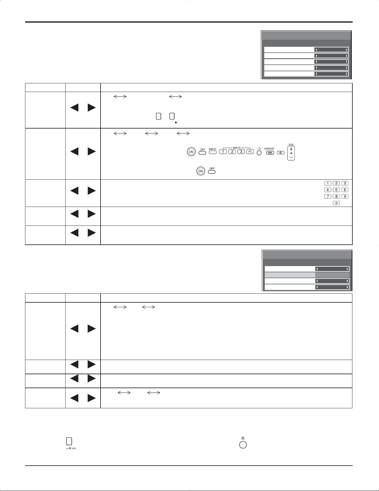
Ajustes de Options (Opciones)
Elemento Efecto Ajustes
Button lock
Remocon
User level
ID select
Remote ID
Serial ID
Off On
Off On
Off MENU&ENTER On
Off (Apagado) :
MENU & ENTER (MENU y ENTER) :
Bloquea los botones
On (Encendido) :
Off User1 User2 User3
Off (Apagado) :
User1 (Usuario 1) :
Usted sólo puede usar los botones , , , , , , , , que se encuentran en
el mando a distancia.
User2 (Usuario 2) :
Usted sólo puede utilizar los botones
User3 (Usuario 3) : Bloquea todos los botones del mando a distancia.
Ajusta el número de ID del panel cuando éste se utiliza en “Remote ID” o en “Serial ID”.
Fije el rango de valor en: 0-100
(Valor estándar: 0)
Off (Apagado) : Desactiva las funciones del ID del mando a distancia.Usted puede utilizar las
On (Encendido) : Activa las funciones del ID del mando a distancia.
Confi gura el Control de ID del panel.
Off (Apagado) : Desactiva el control externo por medio del ID.
On (Encendido) : Activa el control externo por medio del ID.
Pueden utilizarse todos los botones en la parte inferior de la unidad principal.
y
en la cara inferior de la unidad principal.
ENTER/
MENU
Bloquea todos los botones en la cara inferior de la unidad principal.
Usted puede utilizar todos los botones que se encuentran en el mando a distancia.
, , que se encuentran en el mando a distancia.
operaciones normales del mando a distancia.
Options
Button lock
Remocon User level
ID select
Remote ID
Serial ID
2/3
Off
Off
0
Off
Off
Options
Slot power
V. lnstallation
Rotate
Serial Slot Select
3/3
Off
Off
Off
Slot1
Elemento Efecto Ajustes
Off Auto On
Off (Apagado) : La potencia no se transmite a la potencia de la ranura.
Auto : La potencia se transmite a la potencia de la ranura solamente cuando la potencia
principal está activada.
Slot Power
On (Encendido) :La potencia se transmite a la potencia de la ranura cuando la potencia principal
está activada o en espera.
Nota:
En algunos casos, la potencia se transmite a la potencia de la ranura cuando la potencia principal está
activada o en modo de espera, independientemente de la confi guración de potencia de la ranura.
V.Installation
Rotate
Serial Slot
Select
Off On
Off On
Nota: Este modo no está disponible.
Off (Apagado) : No gira la imagen.
On (Encendido) : Gira la imagen a 180 grados.
Slot1 Slot2 Slot3
Selecciona la ranura que se comunica en serie.
Nota:
El ajuste de un comando externo sólo se puede establecer desde el terminal serial fi jo (vea la página 9).
Normalización
Cuando tanto los botones de la unidad principal como el mando a distancia se encuentran desactivados debido a las
configuraciones del “Button lock” (Bloqueador de botones), “Remocon User level” (Nivel de mando a distancia del usuario)
o “Remote ID” (ID del mando a distancia), fije todos los valores en “Off” para volver a activar todos los botones.
Pulse el botón
que se encuentra en la unidad principal, junto con el botón que se ubica en el mando a distancia,
y manténgalos presionados durante más de 5 segundos. “SHIPPING (menú por defecto)” se visualiza y el bloqueo se
destraba cuando desaparece.
37
Page 82
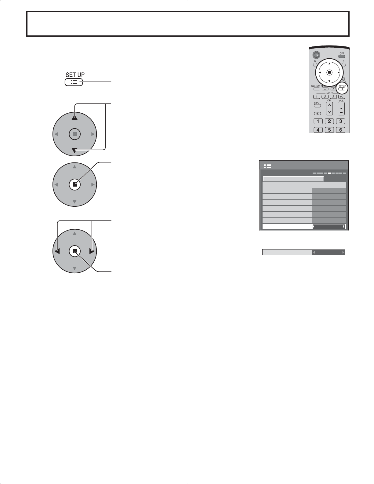
Estado de transporte
Esta función permite restablecer la unidad a los valores de fábrica.
1
Presione para mostrar la pantalla “Configuración”.
2
3
4
Presione para seleccionar “Idioma de OSD”.
Mantenga presionado hasta que aparezca el
menú SHIPPING.
Presione para seleccionar “YES”.
Presione para confirmar.
Configuración
Seleccione entrada componente/RGB
Etiqueta de entrada
Ahorro de consumo
Ahorro en reposo
Energía monitor
Autoapagado
Idioma de OSD Español
SHIPPING
Señal
RGB
PC
Apagado
Apagado
Apagado
Apagado
YES
1/2
[En la unidad]
1 Presione el botón MENU hasta que aparezca el menú Configuración.
2 Presione el botón de subida “+” o bajada “–” del volumen para seleccionar “Idioma de OSD”.
3 Mantenga presionado la tecla ENTER hasta que aparezca el menú SHIPPING.
4 Presione el botón de subida “+” o bajada “–” del volumen para seleccionar “YES”.
5 Presione la tecla ENTER.
Nota:
Presione el botón R para volver al menú Configuración cuando aparezca el menú SHIPPING.
38
Page 83
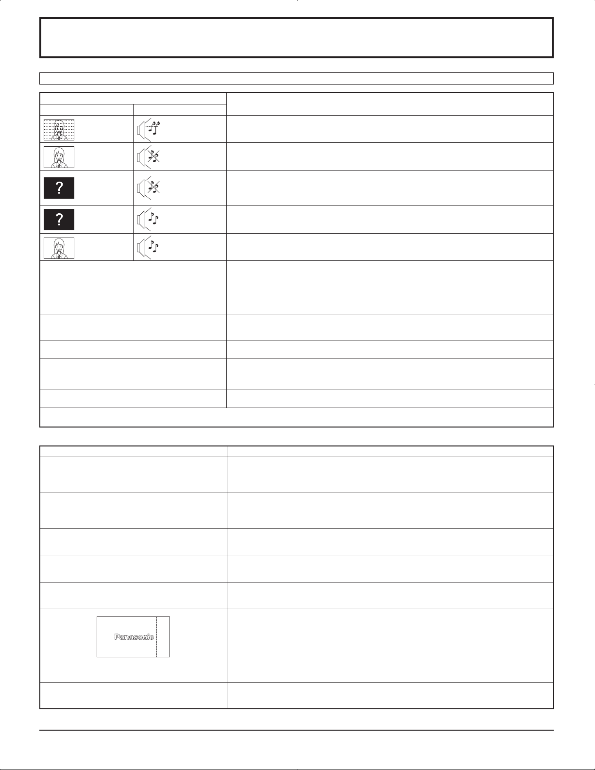
Localización de averías
Antes de acudir al servicio técnico, determine los síntomas y haga algunas verificaciones sencillas como se indica a continuación.
Síntomas
Imagen Sonido
Interferencia
Imagen normal No hay sonido
No hay imagen
No hay imagen
No hay color Sonido normal
No se pueden realizar operaciones con el mando a
distancia.
A veces se oye un crujido en la unidad. Si no hay problemas de imagen o sonido, se trata del sonido de la caja sometida a contracciones
La parte superior o inferior de la imagen de la
pantalla se corta al utilizar la función de zoom.
Al utilizar la función de zoom aparecen zonas donde
no hay imagen en la parte superior e inferior de la
pantalla.
Se oyen sonidos procedentes de la unidad. Al encender la unidad puede oírse un sonido de funcionamiento del panel de la pantalla: Es
Esta pantalla de plasma utiliza un procesamiento de imagen especial. Por eso, dependiendo del tipo de señal de entrada, puede producirse un ligero
retraso entre la aparición de la imagen y el sonido. Sin embargo, esto no indica ningún fallo en el funcionamiento.
Sonido con
ruidos
No hay sonido
Sonido normal
Aparatos electrodomésticos
Coches/motocicletas
Luces fluorescentes
Volumen
(Verifique si no se ha activado la función de silenciamiento en el control
remoto.)
No está enchufado en el tomacorriente de CA
No está conectado
Ajuste de Contraste y Brillo/Volumen (Verifique presionando el interruptor principal o el botón
de espera en el control remoto.)
Si entra una señal con un sistema de color, formato o frecuencia no aplicables, sólo aparece
la indicación de terminal de entrada..
Controles de color ajustados a su nivel mínimo.
(vea la página 22, 23)
Sistema de color (vea la página 33)
Compruebe si se han agotado las pilas; en caso negativo, asegúrese de que estén bien
colocadas.
Compruebe si el sensor de control remoto está expuesto a la luz exterior o a una luz fluorescente
fuerte.
Asegúrese de estar utilizando el mando a distancia diseñado específicamente para esta unidad.
(La unidad no se puede manejar con otro mando a distancia.)
muy leves debidas a cambios en la temperatura de la habitación. Esto no tiene efectos adversos
sobre el rendimiento u otros aspectos.
Ajuste la posición de la imagen en la pantalla.
Si se utiliza un programa de software para vídeo (como un programa para formato de cine) en
una pantalla más ancha que la del modo 16:9, en la parte superior e inferior de la pantalla se
forman zonas en blanco separadas de las imágenes.
algo normal y no indica ningún mal funcionamiento.
Verificaciones
Panel de pantalla de plasma
Síntomas Verificaciones
La pantalla se oscurece ligeramente cuando se
muestran imágenes brillantes con movimientos
mínimos.
La imagen tarda en aparecer. La unidad procesa digitalmente las distintas señales para reproducir imágenes estéticamente
Los bordes de las imágenes parpadean. Debido a las características del sistema empleado para hacer funcionar el panel, puede que
Cambia el brillo de los dos lados
de las imágenes en el modo 4:3.
Algunas partes de la pantalla no
se encienden.
Aparece una imagen fantasma
[Para TH-37PR9U, TH-42PR9U]
Se pueden oír sonidos de runruneo desde la
pantalla.
La pantalla se oscurece ligeramente cuando se visualizan fotos, imágenes fijas de un ordenador
u otras imágenes con movimientos mínimos durante un período de tiempo prolongado. Esta
función sirve para reducir el efecto de imagen secundaria en la pantalla y el acortamiento de
la vida útil de la pantalla: Es algo normal y no indica ningún mal funcionamiento.
agradables. En consecuencia, a veces la imagen tarda un poquito en aparecer al encender la
unidad, al cambiar de entrada o cuando se intercambian las imágenes de la imagen principal
y de la secundaria en las dos pantallas.
parezca que parpadeen los bordes en las partes que se mueven rápidamente en las imágenes:
Es algo normal y no indica ningún mal funcionamiento.
Si se visualizan los paneles laterales con el ajuste “Alto” o “Medio”, el brillo de ambos lados
puede cambiar según el tipo de programa que se visualice: Es algo normal y no indica ningún
mal funcionamiento.
El panel de la pantalla de plasma se ha fabricado con una tecnología de alto nivel de precisión,
sin embargo puede haber partes de la pantalla donde falten elementos de imagen o tengan
puntos siempre iluminados. Esto no es un síntoma de avería.
No permita que una imagen fija se muestre durante mucho tiempo, porque esto puede ser la
causa de que quede una imagen fantasma permanente en la pantalla de plasma.
Los ejemplos de imágenes fijas incluyen logotipos, videojuegos, imágenes de computadora,
teletexto e imágenes mostradas en el formato 4:3.
Nota:
La imagen secundaria permanente en la pantalla de plasma debida a la utilización de una imagen
fija no es un defecto de funcionamiento y, por lo tanto, no está cubierta por la garantía. Este
producto no ha sido diseñado para visualizar imágenes fijas durante largos plazos de tiempo.
La pantalla está equipada con un ventilador de refrigeración para disipar el calor generado
durante el funcionamiento normal. El sonido de runruneo lo causa la rotación del ventilador y
no es ningún fallo de funcionamiento.
39
Page 84

Señales de entrada de PC
Señales de entrada aplicables para Mini D-sub 15P (Componente) / Mini D-sub 15P (RGB) (
Nombre de la señal
1 525 (480) / 60i 15,73 59,94
2 525 (480) / 60p 31,47 59,94
3 625 (575) / 50i 15,63 50,00
4 625 (575) / 50p 31,25 50,00
5 750 (720) / 60p 45,00 60,00
6 750 (720) / 50p 37,50 50,00
7 1.125 (1.080) / 60i 33,75 60,00
8 1.125 (1.080) / 50i 28,13 50,00
9 1.125 (1.080) / 24p 27,00 24,00
10 1.125 (1.080) / 24sF 27,00 47,92
11 1.125 (1.080) / 25p 28,13 25,00
12 1.125 (1.080) / 30p 33,75 30,00
13 1.250 (1.080) / 50i 31,25 50,00
14 640 × 400 @70 Hz 31,46 70,07
15 640 × 480 @60 Hz 31,47 59,94
16 640 × 480 @72 Hz 37,86 72,81
17 640 × 480 @75 Hz 37,50 75,00
18 640 × 480 @85 Hz 43,27 85,01
19 852 × 480 @60 Hz 31,47 59,94
20 800 × 600 @56 Hz 35,16 56,25
21 800 × 600 @60 Hz 37,88 60,32
22 800 × 600 @72 Hz 48,08 72,19
23 800 × 600 @75 Hz 46,88 75,00
24 800 × 600 @85 Hz 53,67 85,06
25 1.024 × 768 @60 Hz 48,36 60,00
26 1.024 × 768 @70 Hz 56,48 70,07
27 1.024 × 768 @75 Hz 60,02 75,03
28 1.024 × 768 @85 Hz 68,68 85,00
29 1.152 × 864 @75 Hz 67,50 75,00
30 1.280 × 960 @60 Hz 60,00 60,00
31 1.280 × 960 @85 Hz 85,94 85,00
32 1.280 × 1.024 @60 Hz 63,98 60,02
33 1.280 × 1.024 @75 Hz 79,98 75,03
34 1.280 × 1.024 @85 Hz 91,15 85,02
35 1.600 × 1.200 @60 Hz 75,00 60,00
36 1.600 × 1.200 @65 Hz 81,25 65,00
37 1.066 × 600 @60 Hz 37,88 60,32
38 1.366 × 768 @60 Hz 48,36 60,00
39 Macintosh13” (640 × 480) 35,00 66,67
40 Macintosh16” (832 × 624) 49,72 74,54
41 Macintosh21” (1.152 × 870) 68,68 75,06
Frecuencia
horizontal (kHz)
Frecuencia
vertical(Hz)
Mini D-sub 15P
(Componente)
asterisco)
Mini D-sub 15P
(RGB)
1
2
2
1: Cuando se selecciona el formato RGB y la entrada de señal 525p en el terminal Mini D-sub 15P, se reconoce como
señal VGA 60Hz.
2: Al ingresar la señal del formato VGA 60Hz del otro terminal Mini D-sub 15P, se reconoce como señal 525p.
Nota: Las señales sin las especificaciones de arriba puede que no se visualicen correctamente.
40
Page 85
Especificaciones
TH-37PG9U TH-42PG9U
Fuente de alimentación 120 V AC, 50/60 Hz
Fuente de consumo
Corriente conectada 265 W 290 W
Estado de espera
Estado de corriente desconectada
Panel de pantalla de plasma Tipo CA con método directo 37 pulg.,
Relación de contraste 10000:1 máximo
Tamaño de pantalla 32,2” (818 mm) (An.) × 18,1” (461 mm) (Al.)
(Número. de pixeles) 408.960 (852 (An.) × 480 (AI.))
Condiciones de funcionamiento
Temperatura 32 °F - 104 °F (0 °C - 40 °C)
Humedad 20 % - 80 %
Señales aplicables
Scanning format 525 (480) / 60i · 60p, 625 (575) / 50i · 50p, 750 (720) / 60p · 50p, 1125 (1080) / 60i · 50i · 24p · 25p
Señales PC VGA
Terminales de conexión
PC (ALTA DENSIDAD, CONECTOR MINI D-SUB DE 15 CONTACTOS)R,G,B/0,7 Vp-p (75 )
SERIAL
Accesorios suministrados
Banda de fijación (TMME203 o TMME187) × 2
Dimensiones (An × Al. × Prof.)
Masa (Peso) 57,3 lbs 66,1 lbs
Sonido
Altavoces 4,8” (120mm) × 2,4” (60 mm) × 2 piezas, 8
Salida de audio 20 W [10 W + 10 W] (10% de distorsión armónica total)
Protección desactivada 0,6 W, Protección activada 0,4 W Protección desactivada 0,6 W, Protección activada 0,4 W
0,1 W 0,1 W
Tipo CA con método directo 42 pulg.,
relación de aspecto de 16:9
36,2” (920 mm) (An.) × 20,4” (518 mm) (Al.)
× 37” (939 mm) (diagonal)
[2.556 × 480 puntos]
· 30p · 24sF ···· SMPTE274M, 1250 (1080) / 50i
SVGA, XGA, SXGA, UXGA ···· (comprimido)
Frecuencia de exploración horizontal 15 - 110 kHz
Frecuencia de exploración vertical 48 - 120 Hz
HD, VD/1,0 - 5,0 Vp-p (alta impedancia)
Componente
Y : 1,0 Vp-p (75 : incluye sincronización)
P
P
AUDIO IN (
TERMINAL DE CONTROL EXTERIOR (CONECTOR D-SUB DE 9 CONTACTOS) RS-232C COMPATIBLE
36,1” (917 mm) × 25,4” (644 mm) × 3,7” (95 mm)
(4,3” (109 mm) cuando se incluyen las partes
Toma de 3,5 ø
sobresalientes de las ranuras)
B/CB : 0,7 Vp-p (75 )
R/CR : 0,7 Vp-p (75 )
) 0,5 Vrms (alta impedancia)
40,2” (1.020 mm) × 27,8” (705 mm) × 3,7” (95 mm)
(4,3” (109 mm) cuando se incluyen las partes
16:9 aspect ratio
× 42” (1.056 mm) (diagonal)
sobresalientes de las ranuras)
Nota:
El diseño y especificaciones están sujetos a cambios sin previo aviso. El Masa y dimensiones son aproximados.
41
Page 86
Especificaciones
TH-37PR9U TH-42PR9U
Fuente de alimentación 120 V AC, 50/60 Hz
Fuente de consumo
Corriente conectada 300 W 345 W
Estado de espera
Estado de corriente desconectada
Panel de pantalla de plasma Tipo CA con método directo 37 pulg.,
Relación de contraste 10000:1 máximo
Tamaño de pantalla 32,2” (818 mm) (An.) × 18,1” (461 mm) (Al.)
(Número. de pixeles) 737.280 (1.024 (An.) × 720 (AI.))
Condiciones de funcionamiento
Temperatura 32 °F - 104 °F (0 °C - 40 °C)
Humedad 20 % - 80 %
Señales aplicables
Scanning format 525 (480) / 60i · 60p, 625 (575) / 50i · 50p, 750 (720) / 60p · 50p, 1125 (1080) / 60i · 50i · 24p · 25p
Señales PC
Terminales de conexión
PC (ALTA DENSIDAD, CONECTOR MINI D-SUB DE 15 CONTACTOS)R,G,B/0,7 Vp-p (75 )
SERIAL
Accesorios suministrados
Banda de fijación (TMME203 o TMME187) × 2
Dimensiones (An × Al. × Prof.)
Masa (Peso) 57,3 lbs 66,1 lbs
Sonido
Altavoces 4,8” (120mm) × 2,4” (60 mm) × 2 piezas, 8
Salida de audio 20 W [10 W + 10 W] (10% de distorsión armónica total)
Protección desactivada 0,6 W, Protección activada 0,4 W Protección desactivada 0,6 W, Protección activada 0,4 W
0,1 W 0,1 W
Tipo CA con método directo 42 pulg.,
relación de aspecto de 16:9
36,2” (920 mm) (An.) × 20,4” (518 mm) (Al.)
× 37” (939 mm) (diagonal)
786.432 (1.024 (An.) × 768 (AI.))
[3.072 × 720 puntos]
· 30p · 24sF ···· SMPTE274M, 1250 (1080) / 50i
VGA, SVGA,
XGA, SXGA, UXGA ···· (comprimido)
Frecuencia de exploración horizontal 15 - 110 kHz
Frecuencia de exploración vertical 48 - 120 Hz
HD, VD/1,0 - 5,0 Vp-p (alta impedancia)
Componente
Y : 1,0 Vp-p (75 : incluye sincronización)
P
P
AUDIO IN (
TERMINAL DE CONTROL EXTERIOR (CONECTOR D-SUB DE 9 CONTACTOS) RS-232C COMPATIBLE
36,1” (917 mm) × 25,4” (644 mm) × 3,7” (95 mm)
(4,3” (109 mm) cuando se incluyen las partes
Toma de 3,5 ø
sobresalientes de las ranuras)
B/CB : 0,7 Vp-p (75 )
R/CR : 0,7 Vp-p (75 )
) 0,5 Vrms (alta impedancia)
Frecuencia de exploración horizontal 15 - 110 kHz
Frecuencia de exploración vertical 48 - 120 Hz
40,2” (1.020 mm) × 27,8” (705 mm) × 3,7” (95 mm)
(4,3” (109 mm) cuando se incluyen las partes
16:9 aspect ratio
× 42” (1.056 mm) (diagonal)
[3.072 × 768 puntos]
VGA, SVGA, XGA,
SXGA, UXGA ···· (comprimido)
sobresalientes de las ranuras)
Nota:
El diseño y especificaciones están sujetos a cambios sin previo aviso. El Masa y dimensiones son aproximados.
42
Page 87

Registro del cliente
El número de modelo y número de serie de este producto están en la cubierta trasera. Debe anotar este número de
serie en el espacio a continuación y guardar este libro junto con el recibo de compra como registro permanente de su
compra para ayudar a identificarlo en el caso de robo o pérdida y para el servicio bajo garantía.
Número de modelo Número de serie
Matsushita Electric Industrial Co., Ltd.
2006 Matsushita Electric Industrial Co., Ltd. All Rights Reserved.
©
Impreso en Japón
MBS0306A1046
 Loading...