

PANASONIC TH-42PG10R User Manual
Operating Instructions
Progressive Wide Hospitality Plasma Display
Model No.
TH-42PG10R
High Defi nition Hospitality Plasma Display
Model No.
TH-37PR10R
TH-42PR10R
Please read these instructions before operating your set
and retain them for future reference.
English
The illustration shown is an image.
ME67

Dear Panasonic Customer
Welcome to the Panasonic family of customers. We hope that you will have many years of
enjoyment from your new Plasma Display.
To obtain maximum benefit from your set, please read these Instructions before making
any adjustments, and retain them for future reference.
Retain your purchase receipt also, and note down the model number and serial number of
your set in the space provided on the rear cover of these instructions.
Visit our Panasonic Web Site http://panasonic.net
Table of Contents
Important Safety Notice ........................................... 3
Safety Precautions ................................................... 4
Accessories .............................................................. 7
Accessories Supply ................................................. 7
Connections .............................................................. 8
PC Input Terminals connection ................................ 9
SERIAL Terminals connection ............................... 10
Power On / Off ......................................................... 11
Basic Controls ........................................................ 12
On-Screen Menu Displays ..................................... 14
Initial selections ..................................................... 16
Selecting the input signal ...................................... 16
Selecting the On-Screen Menu Language ............ 16
ASPECT Controls ................................................... 17
Adjusting Pos. /Size ............................................... 18
MULTI PIP ................................................................ 19
Advanced PIP .......................................................... 20
Picture Adjustments ............................................... 21
Advanced settings ................................................. 22
Sound Adjustment .................................................. 24
Mute ...................................................................... 24
Digital Zoom ............................................................ 25
PRESENT TIME Setup / Set up TIMER .................. 26
PRESENT TIME Setup .......................................... 26
Set up TIMER ........................................................ 27
Screensaver (For preventing image retention) .... 28
Setup of Screensaver Time ................................... 29
Reduces screen image retention ........................... 29
Side Panel Adjustment .......................................... 30
Reduces power consumption ............................... 31
Customizing the Input labels ................................. 31
Setup for Input Signals .......................................... 32
Component / RGB-in select ................................... 32
3D Y/C Filter .......................................................... 32
Colour system / Panasonic Auto ........................... 33
Cinema reality / P-NR ............................................ 33
Sync ...................................................................... 34
Refresh Rate (for TH-37PR10R, TH-42PR10R) .... 34
H-Freq. (kHz) / V-Freq. (Hz) .................................. 34
Options Adjustments ............................................. 35
Weekly Command Timer
(for TH-37PR10R, TH-42PR10R) .......................... 42
Shipping condition ................................................. 44
Troubleshooting ..................................................... 45
PC input signals ..................................................... 46
Command list of Weekly Command Timer ........... 47
Specifi cations ......................................................... 48
2
Important Safety Notice
WARNING
1) To prevent damage which may result in fi re or shock hazard, do not expose this appliance to dripping
or splashing.
Do not place containers with water (fl ower vase, cups, cosmetics, etc.) above the set. (including on
shelves above, etc.)
No naked fl ame sources, such as lighted candles, should be placed on / above the set.
2) To prevent electric shock, do not remove cover. No user serviceable parts inside. Refer servicing to qualifi ed
service personnel.
3) Do not remove the earthing pin on the power plug. This apparatus is equipped with a three pin earthing-type
power plug. This plug will only fi t an earthing-type power outlet. This is a safety feature. If you are unable to
insert the plug into the outlet, contact an electrician.
Do not defeat the purpose of the earthing plug.
4) To prevent electric shock, ensure the earthing pin on the AC cord power plug is securely connected.
CAUTION
This appliance is intended for use in environments which are relatively free of electromagnetic fi elds.
Using this appliance near sources of strong electromagnetic fi elds or where electrical noise may overlap with the
input signals could cause the picture and sound to wobble or cause interference such as noise to appear.
To avoid the possibility of harm to this appliance, keep it away from sources of strong electromagnetic fi elds.
Trademark Credits
• VGA is a trademark of International Business Machines Corporation.
• Macintosh is a registered trademark of Apple Computer, USA.
• S-VGA is a registered trademark of the Video Electronics Standard Association.
Even if no special notation has been made of company or product trademarks, these trademarks have been
fully respected.
Note:
Do not allow a still picture to be displayed for an extended period, as this can cause a permanent image retention
to remain on the Plasma Display.
Examples of still pictures include logos, video games, computer images, teletext and images displayed in 4:3
mode.
3

Safety Precautions
WARNING
Setup
This Plasma Display is for use only with the following optional accessories. Use with any other type of optional
accessories may cause instability which could result in the possibility of injury.
(All of the following accessories are manufactured by Matsushita Electric Industrial Co., Ltd.)
• Pedestal ..............................................................................................................TY-ST09GR-K
• Wall-hanging bracket (vertical) ............................................................................TY-WK42PV3W
• Wall-hanging bracket (angled) ............................................................................TY-WK42PR3W
• BNC Component Video Terminal Board ..............................................................TY-42TM6A
• BNC Composite Video Terminal Board ...............................................................TY-42TM6B
• BNC Dual Video Terminal Board ......................................................................... TY-FB9BD
• Ir Through Terminal Board .................................................................................. TY-FB9RT
• RCA Component Video Terminal Board ..............................................................TY-42TM6Z
• RCA Composite Video Terminal Board ...............................................................TY-42TM6V
• PC Input Terminal Board .....................................................................................TY-42TM6P
• RGB (Digital) Terminal Board .............................................................................. TY-42TM6D
• HDMI Terminal Board .......................................................................................... TY-FB8HM
• SCART Terminal Board ....................................................................................... TY-FB8SC
• U/V Tuner Board with Hospitality Port .................................................................TY-FB9TE
• Set Up Loader .....................................................................................................TY-RM09SL
• AV Terminal BOX .................................................................................................TY-TB10AV
Always be sure to ask a qualifi ed technician to carry out set-up.
Small parts can present choking hazard if accidentally swallowed. Keep small parts away from young children. Discard
unneeded small parts and other objects, including packaging materials and plastic bags/sheets to prevent them from
being played with by young children, creating the potential risk of suffocation.
Do not place the Plasma Display on sloped or unstable surfaces.
• The Plasma Display may fall off or tip over.
Do not place any objects on top of the Plasma Display.
• If water is spills onto the Plasma Display or foreign objects get inside it, a short-circuit may occur which could result
in fi re or electric shock. If any foreign objects get inside the Plasma Display, please consult your local Panasonic
dealer.
Transport only in upright position!
• Transporting the unit with its display panel facing upright or downward may cause damage to the internal
circuitry.
Ventilation should not be impeded by covering the ventilation openings with items such as newspapers, table
cloths and curtains.
For suffi cient ventilation;
If using the pedestal (optional accessory) for the Plasma Display, leave a space of at least 10 cm at the top,
left and right, at least 6 cm at the bottom, and at least 7 cm at the rear. If using some other setting-up method,
leave a space of at least 10 cm at the top, bottom, left and right, and at least 7 cm at the rear.
4

Safety Precautions
When using the Plasma Display
The Plasma Display is designed to operate on 220-240 V AC, 50/60 Hz.
Do not cover the ventilation holes.
• Doing so may cause the Plasma Display to overheat, which can cause fi re or damage to the Plasma Display.
Do not stick any foreign objects into the Plasma Display.
• Do not insert any metal or fl ammable objects into the ventilations holes or drop them onto the Plasma Display, as
doing so can cause fi re or electric shock.
Do not remove the cover or modify it in any way.
• High voltages which can cause severe electric shocks are present inside the Plasma Display. For any inspection,
adjustment and repair work, please contact your local Panasonic dealer.
Ensure that the mains plug is easily accessible.
Do not use any power supply cord other than that provided with this unit.
• Doing so may cause fi re or electric shocks.
Securely insert the power supply plug as far as it will go.
• If the plug is not fully inserted, heat may be generated which could cause fi re. If the plug is damaged or the wall
socket is loose, they shall not be used.
Do not handle the power supply plug with wet hands.
• Doing so may cause electric shocks.
Do not do anything that may damage the power cable. When disconnecting the power cable, pull on the plug
body, not the cable.
• Do not damage the cable, make any modifi cations to it, place heavy objects on top of it, heat it, place it near any
hot objects, twist it, bend it excessively or pull it. To do so may cause fi re and electric shock. If the power cable is
damaged, have it repaired at your local Panasonic dealer.
If the Plasma Display is not going to be used for any prolonged length of time, unplug the power supply plug
from the wall outlet.
If problems occur during use
If a problem occurs (such as no picture or no sound), or if smoke or an abnormal odour starts to come out
from the Plasma Display, immediately unplug the power supply plug from the wall outlet.
• If you continue to use the Plasma Display in this condition, fi re or electric shock could result. After checking that
the smoke has stopped, contact your local Panasonic dealer so that the necessary repairs can be made. Repairing
the Plasma Display yourself is extremely dangerous, and shall never be done.
If water or foreign objects get inside the Plasma Display, if the Plasma Display is dropped, or if the cabinet
becomes damages, disconnect the power supply plug immediately.
• A short circuit may occur, which could cause fi re. Contact your local Panasonic dealer for any repairs that need to
be made.
5

Safety Precautions
CAUTION
When using the Plasma Display
Do not bring your hands, face or objects close to the ventilation holes of the Plasma Display.
• Heated air comes out from the ventilation holes at the top of Plasma Display will be hot. Do not bring your hands
or face, or objects which cannot withstand heat, close to this port, otherwise burns or deformation could result.
Be sure to disconnect all cables before moving the Plasma Display.
• If the Plasma Display is moved while some of the cables are still connected, the cables may become damaged,
and fi re or electric shock could result.
Disconnect the power supply plug from the wall socket as a safety precaution before carrying out any
cleaning.
• Electric shocks can result if this is not done.
Clean the power cable regularly to prevent it becoming dusty.
• If dust built up on the power cord plug, the resultant humidity can damage the insulation, which could result in fi re.
Pull the power cord plug out from the wall outlet and wipe the mains lead with a dry cloth.
This Plasma Display radiates infrared rays, therefore it may affect other infrared communication equipment.
Install your infrared sensor in a place away from direct or refl ected light from your Plasma Display.
Cleaning and maintenance
The front of the display panel has been specially treated. Wipe the panel surface gently using only a cleaning
cloth or a soft, lint-free cloth.
• If the surface is particularly dirty, wipe with a soft, lint-free cloth which has been soaked in pure water or water in
which neutral detergent has been diluted 100 times, and then wipe it evenly with a dry cloth of the same type until
the surface is dry.
• Do not scratch or hit the surface of the panel with fi ngernails or other hard objects, otherwise the surface may
become damaged. Furthermore, avoid contact with volatile substances such as insect sprays, solvents and thinner,
otherwise the quality of the surface may be adversely affected.
If the cabinet becomes dirty, wipe it with a soft, dry cloth.
• If the cabinet is particularly dirty, soak the cloth in water to which a small amount of neutral detergent has been
added and then wring the cloth dry. Use this cloth to wipe the cabinet, and then wipe it dry with a dry cloth.
• Do not allow any detergent to come into direct contact with the surface of the Plasma Display. If water droplets get
inside the unit, operating problems may result.
• Avoid contact with volatile substances such as insect sprays, solvents and thinner, otherwise the quality of the
cabinet surface may be adversely affected or the coating may peel off. Furthermore, do not leave it for long periods
in contact with articles made from rubber or PVC.
6
Accessories
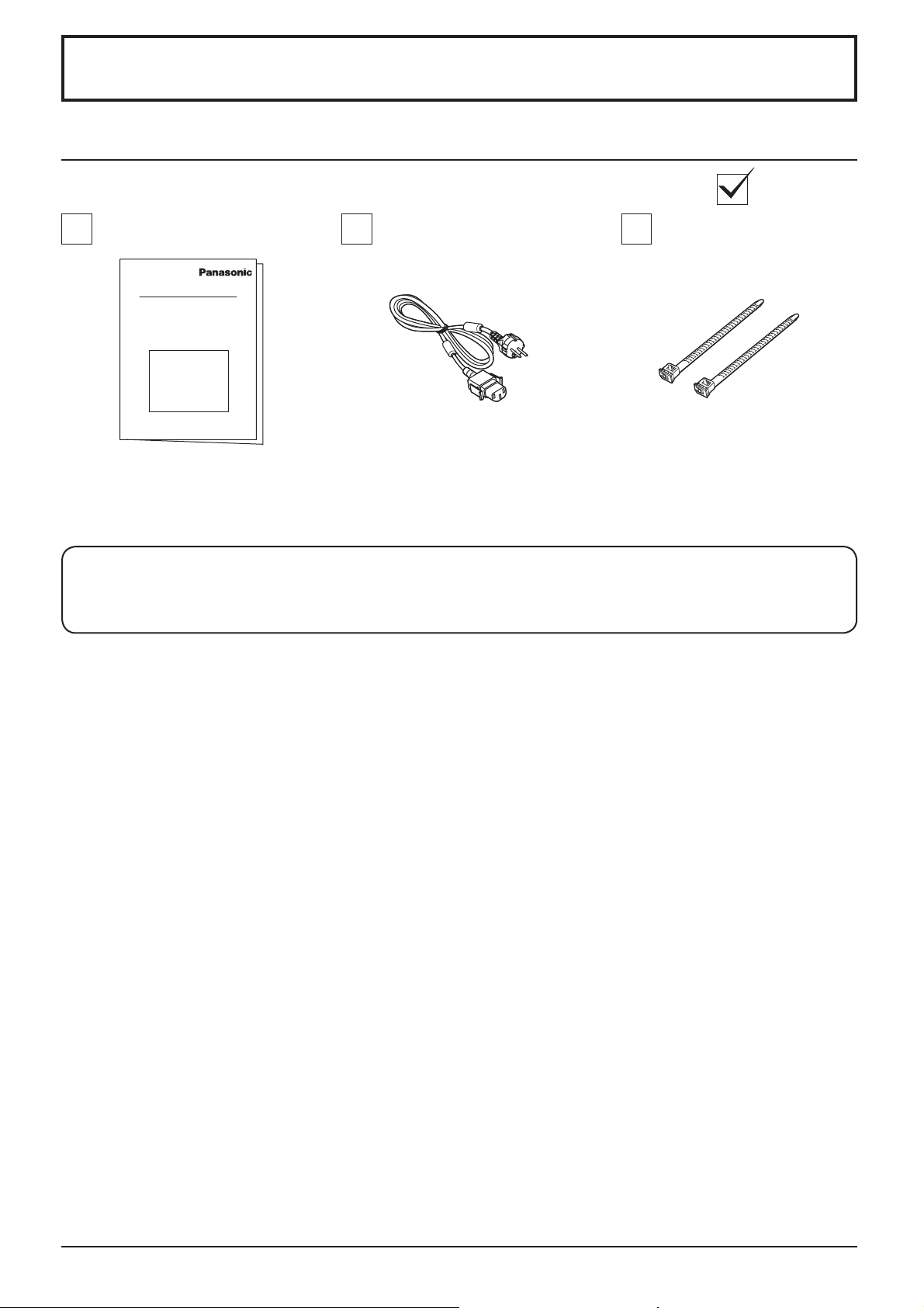
Accessories Supply
Check that you have the accessories and items shown
Fixing bands × 2Power supply cordOperating Instruction book
The remote control is not included with this set. Available for purchase separately.
Object model : EUR7636090R
7
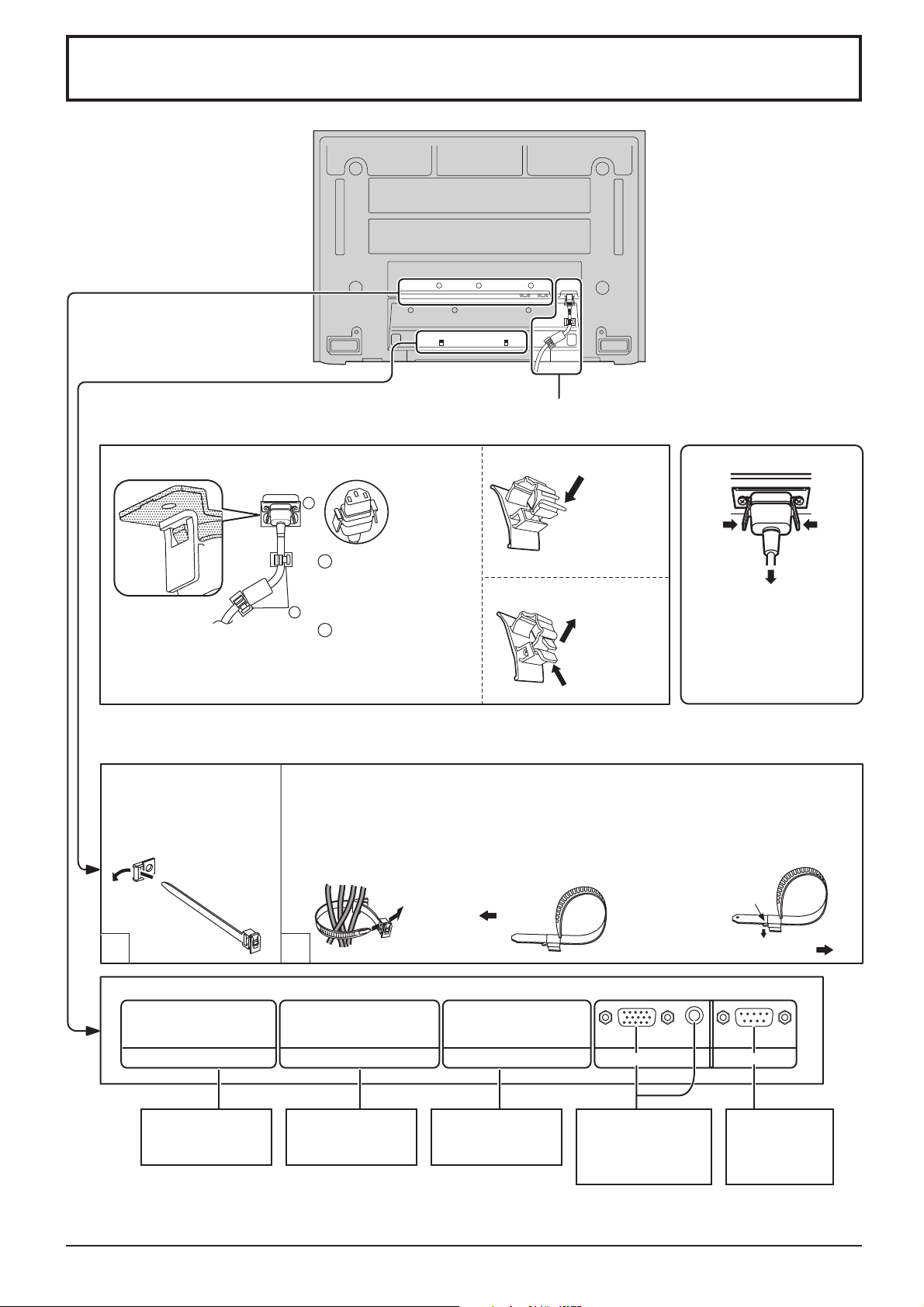
Connections
– AC cord fi xing
AC cord connection (see page 11)
Close
1
Unplug the AC cord
Push until
the hook
clicks.
2. Pull off.
1.
Keep the
knob pressed.
2
Note:
Make sure that the AC cord is locked
on both the left and right sides.
Plug the AC cord into
1
the display unit.
Plug the AC cord until
it clicks.
2
Fix the AC cord with
the clamper which is
attached to the unit.
Open
– Cable fi xing bands Secure any excess cables with bands as required.
Pass the attached cable
fi xing band through the
clip as shown in the
fi gure.
1
To secure cables connected to Terminals, wrap the cable fi xing band around them
then pass the pointed end through the locking block, as shown in the fi gure.
While ensuring there is suffi cient slack in cables to minimize stress (especially
in the power cord), fi rmly bind all cables with the supplied fi xing band.
To tighten: To loosen:
Pull
2
Unplug the AC cord pressing
the two knobs.
Note:
When disconnecting the AC
cord, be absolutely sure to
disconnect the AC cord plug
at the socket outlet fi rst.
Push the catch
Pull
8
SLOT1 SLOT2 SLOT3
Optional Terminal
Board Insert Slot
(covered)
Optional Terminal
Board Insert Slot
(covered)
Optional Terminal
Board Insert Slot
(covered)
AUDIO
From EXTERNAL
monitor terminal
on Computer (see
page 9)
SERIALPC IN
From SERIAL
Terminal
on Computer
(see page 10)
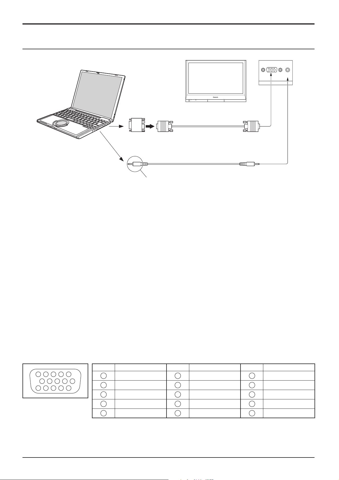
PC Input Terminals connection
COMPUTER
Conversion adapter
(if necessary)
RGB
PC cable
Connections
AUDIO
PC IN
Mini D-sub 15p
Audio
Connect a cable which matches
the audio output terminal on the computer.
Stereo plug
Notes:
• Due to space limitations, occasionally you may have trouble connecting Mini D-sub 15P cable with ferrite core to PC input
Terminal.
• Computer signals which can be input are those with a horizontal scanning frequency of 15 to 110 kHz and vertical scanning
frequency of 48 to 120 Hz. (However, the image will not be displayed properly if the signals exceed 1,200 lines.)
• The display resolution is a maximum of 768 × 720 dots (TH-37PR10R), 768 × 768 dots (TH-42PR10R), 640 × 480
dots (TH-42PG10R) when the aspect mode is set to “4:3”, and 1,024 × 720 dots (TH-37PR10R), 1,024 × 768 dots
(TH-42PR10R), 852 × 480 dots (TH-42PG10R) when the aspect mode is set to “16:9”. If the display resolution
exceeds these maximums, it may not be possible to show fi ne detail with suffi cient clarity.
• The PC input terminals are DDC2B-compatible. If the computer being connected is not DDC2B-compatible, you will
need to make setting changes to the computer at the time of connection.
• Some PC models cannot be connected to the set.
• There is no need to use an adapter for computers with DOS/V compatible Mini D-sub 15P terminal.
• The computer shown in the illustration is for example purposes only.
• Additional equipment and cables shown are not supplied with this set.
• Do not set the horizontal and vertical scanning frequencies for PC signals which are above or below the specifi ed
frequency range.
• Component Input is possible with the pin 1, 2, 3 of the Mini D-sub 15P Connector.
• Change the “Component/RGB-in select” setting in the “Setup” menu to “Component” (when Component connection)
or “RGB” (when RGB signal connection). (see page 32)
Signal Names for Mini D-sub 15P Connector
Pin No. Signal Name Pin No. Signal Name Pin No. Signal Name
45
10
15 14 13 12 11
Pin Layout for PC Input
Terminal
1
2
67839
1
2
3
4
5
R (PR/CR)
B (PB/CB)
NC (not connected)
GND (Ground)
G (Y)
6
7
8
9
10
GND (Ground)
GND (Ground)
GND (Ground)
NC (not connected)
GND (Ground)
11
NC (not connected)
12
13
14
15
HD/SYNC
SDA
VD
SCL
9
Connections
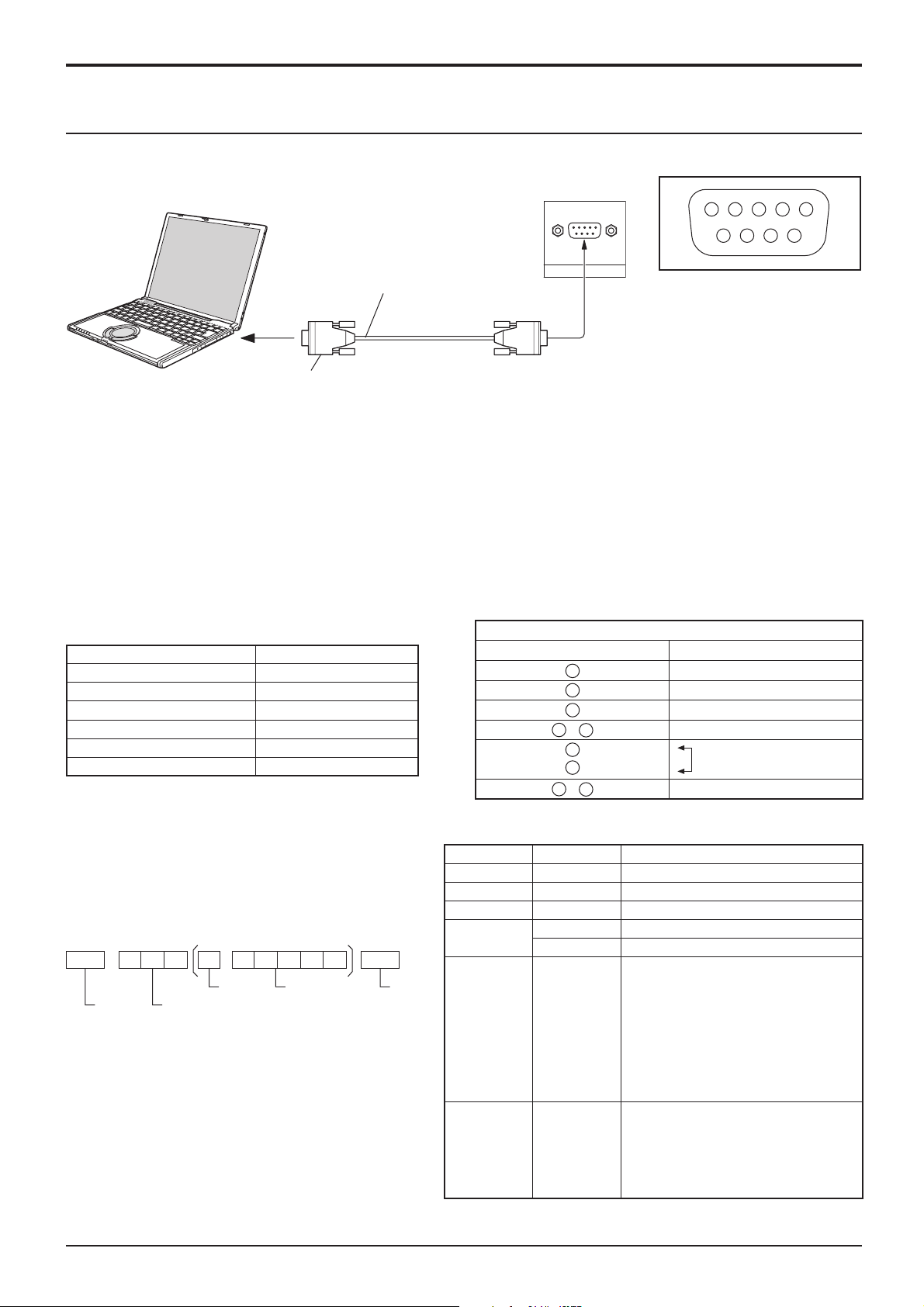
SERIAL Terminals connection
The SERIAL terminal is used when the Plasma Display is controlled by a computer.
COMPUTER
RS-232C Straight cable
SERIAL
Pin layout for SERIAL Terminal
13452
6789
D-sub 9p
Notes:
• Use the RS-232C cable to connect the computer to the Plasma Display.
• The computer shown is for example purposes only.
• Additional equipment and cables shown are not supplied with this set.
The SERIAL terminal conforms to the RS-232C interface specifi cation, so that the Plasma Display can be controlled
by a computer which is connected to this terminal.
The computer will require software which allows the sending and receiving of control data which satisfi es the conditions
given below. Use a computer application such as programming language software. Refer to the documentation for
the computer application for details.
Communication parameters
Signal level RS-232C compliant
Synchronization method Asynchronous
Baud rate 9600 bps
Parity None
Character length 8 bits
Stop bit 1 bit
Flow control -
D-sub 9-pin female Details
RS-232C Conversion cable
2
3
5
4
6
•
7
8
1
9
•
R X D
T X D
GND
Non use
Shorted
NC
Basic format for control data
The transmission of control data from the computer
starts with a STX signal, followed by the command,
the parameters, and lastly an ETX signal in that order.
If there are no parameters, then the parameter signal
does not need to be sent.
STX C1 C2 C3 P1 P2 P3 P4: P5 ETX
Start
(02h)
Colon Parameter(s)
3-character
command (3 bytes)
(1 - 5 bytes)
End
(03h)
Notes:
• If multiple commands are transmitted, be sure to wait
for the response for the fi rst command to come from
this unit before sending the next command.
• If an incorrect command is sent by mistake, this
unit will send an “ER401” command back to the
computer.
• SL1A, SL1B, SL2A and SL2B of Command IMS are
available only when a dual input terminal board is
attached.
10
Command
Command Parameter Control details
PON None Power ON
POF None Power OFF
AVL ** Volume 00 - 63
AMT
IMS None
DAM None
0 Audio MUTE OFF
1 Audio MUTE ON
Input select (toggle)
SL1
SL2
SL3
PC1
SL1A
SL1B
SL2A
SL2B
NORM
ZOOM
FULL
JUST
SELF
Slot1 input
Slot2 input
Slot3 input
PC input
Slot1 input (INPUT1A)
Slot1 input (INPUT1B)
Slot2 input (INPUT2A)
Slot2 input (INPUT2B)
Screen mode select (toggle)
NORMAL (4 : 3)
ZOOM
FULL
JUST
Panasonic AUTO
With the power off, this display responds to PON command only.
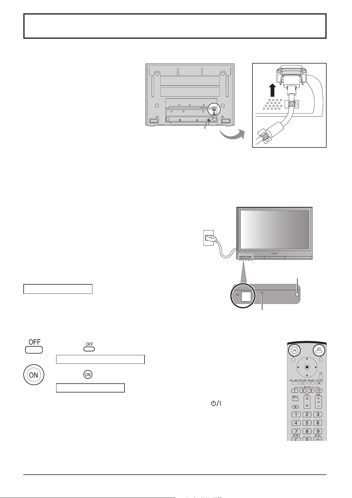
Power On / Off
Connecting the AC cord plug to the Plasma Display.
Fix the AC cord plug securely to the
Plasma Display with the clamper.
(see page 8)
Connecting the plug to the Wall Outlet.
Notes:
• Main plug types vary between countries. The power plug shown
at right may, therefore, not be the type fi tted to your set.
• When disconnecting the AC cord, be absolutely sure to
disconnect the AC cord plug at the socket outlet fi rst.
Press the Power switch on the Plasma Display to turn the set
on: Power-On.
Power Indicator: Green
Example: The screen below is displayed for a while after the
Plasma Display is turned on (setting condition is an
example).
Press the button on the remote control to turn the Plasma Display off.
Power Indicator: Red (standby)
Press the button on the remote control to turn the Plasma Display on.
Remote Control Sensor
Power Indicator
Power Indicator: Green
Turn the power to the Plasma Display off by pressing the
unit, when the Plasma Display is on or in standby mode.
Note:
During operation of the power management function, the power indicator turns
orange in the power off state.
switch on the
11
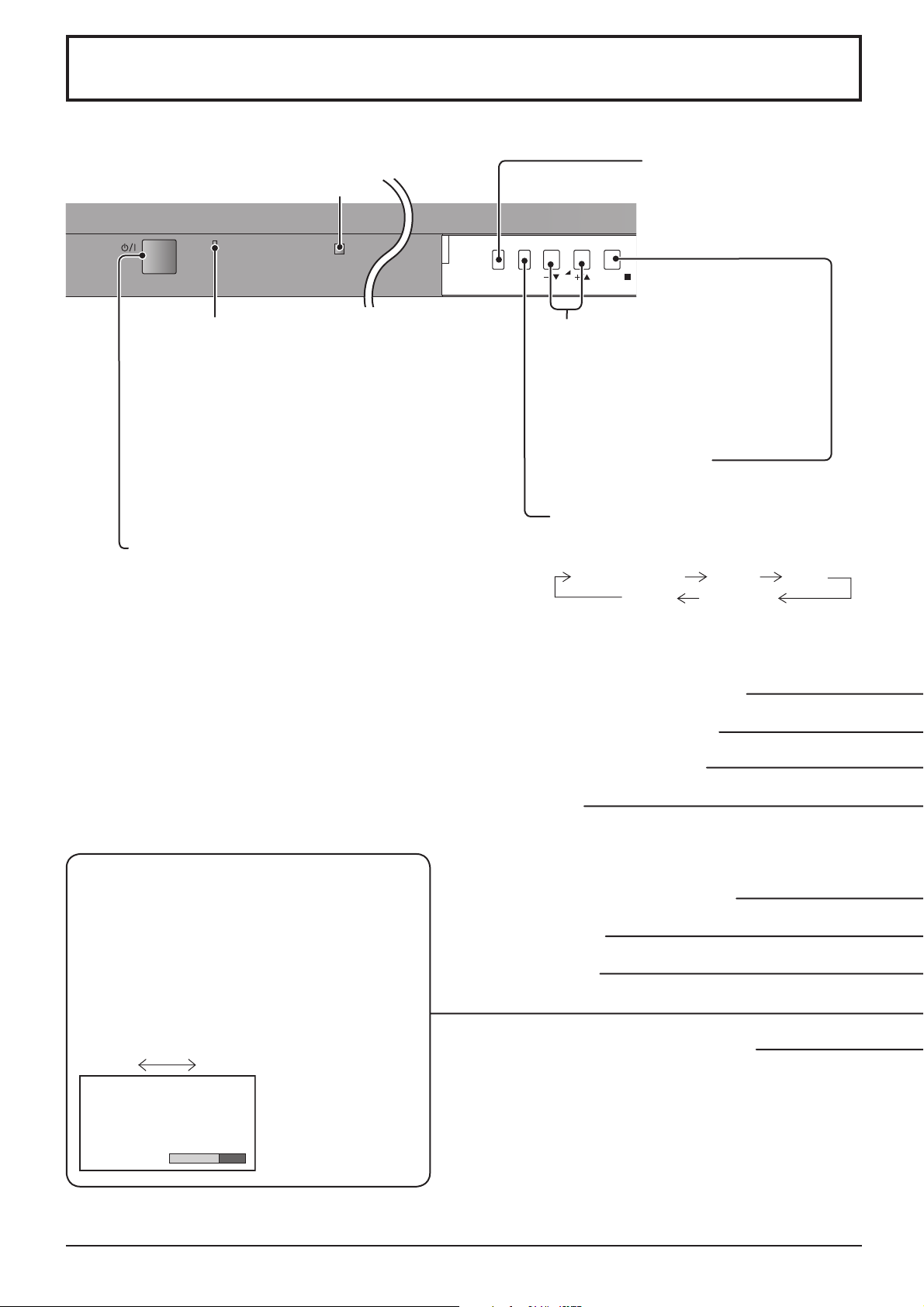
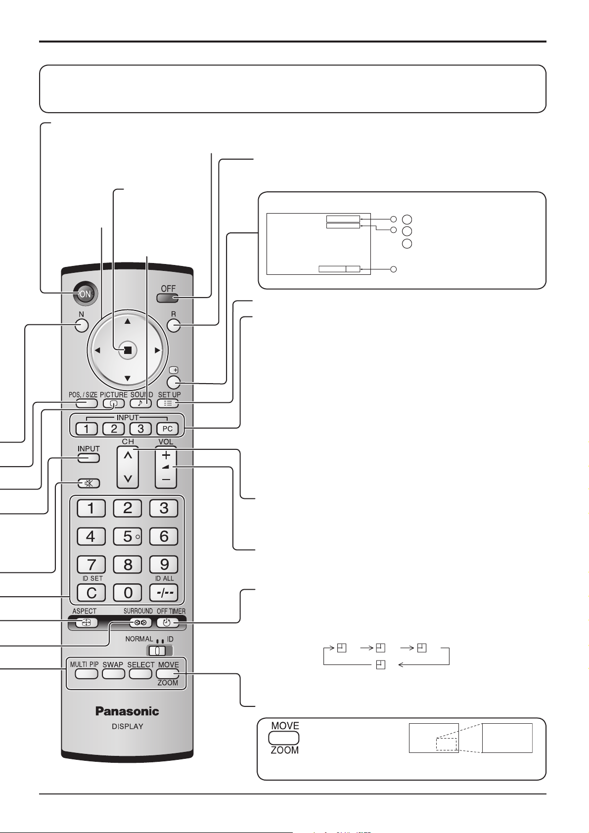
Basic Controls
Remote control sensor
INPUT
MENU
VOL
INPUT button
(INPUT1, INPUT2, INPUT3
and PC selection)
(see page 16)
ENTER/
Power Indicator
The Power Indicator will light.
• Power-OFF .... Indicator not illuminated (The unit
will still consume some power
as long as the power cord is still
inserted into the wall outlet.)
• Standby .......... Red
• Power-ON ...... Green
• DPMS .............Orange (With PC input signal
and during operation of PC’s
screensaver.)
Main Power On / Off Switch
N button (see page 18, 21, 22, 23, 24)
POS. / SIZE button (see page 18)
PICTURE button (see page 21)
Volume Adjustment
Volume Up “+” Down “–”
When the menu screen is displayed:
“+”: press to move the cursor up
“–”: press to move the cursor down
(see page 14)
Enter / Aspect button
(see page 14, 17)
MENU Screen ON / OFF
Each time the MENU button is pressed, the
menu screen will switch. (see page 14)
Normal Viewing Picture Setup
Sound Pos. /Size
SURROUND button
The surround setting switches on and off each time
the SURROUND button is pressed.
The benefi ts of surround sound are enormous. You
can be completely enveloped in sound; just as if
you were at a concert hall or cinema.
Note:
The surround settings are memorized separately
for each Sound Mode (Normal, Dynamic, Clear).
On Off
Surround
On
INPUT button
(INPUT1, INPUT2, INPUT3 and PC selection)
Press to select INPUT1, INPUT2, INPUT3 and PC input
SLOTS sequentially. (see page 16)
Sound mute On / Off (see page 24)
Numeric buttons
ASPECT button
Press to adjust the aspect. (see page 17)
MULTI Window buttons (see page 19)
12
Basic Controls
The remote control is not included with this set. Available for purchase separately.
Object model : EUR7636090R
Standby (ON / OFF) button
The Plasma Display must fi rst be plugged into the wall outlet and turned on at the power switch (see page 11).
Press ON to turn the Plasma Display On, from Standby mode. Press OFF to turn the Plasma Display Off to Standby
mode.
POSITION
buttons
ACTION button
Press to make
selections.
SOUND button
(see page 24)
R button (see page 15)
Press the R button to return to previous menu screen.
Status button
Press the “Status” button to display the current system status.
PC
4:3
1
Input label
1
2
2
Aspect mode (see page 17)
Off timer
3
The off timer indicator is
Off timer 90
displayed only when the off
3
timer has been set.
SET UP button (see page 14, 15)
DIRECT INPUT buttons
Press the INPUT “1”, “2”, “3” or “PC” input mode selection button to
select the input mode.
This button is used to switch directly to INPUT mode.
These buttons can only display the slot which is installed. If you
press the button whose slot is not installed, it automatically displays
the current input signal.
When a dual input terminal board is attached, A or B is displayed
depending on the selected input signal. (Ex. INPUT1A, INPUT1B)
Note:
Image retention (image lag) may occur on the plasma display panel
when a still picture is kept on the panel for an extended period. The
function that darkens the screen slightly is activated to prevent image
retention (see page 45), this function is not the perfect solution to
image retention.
Channel Adjustment
You can use this button when U/V Tuner Board with Hospitality Port
is installed (optional accessories). Refer to each Board's Operating
Instruction for detail.
Volume Adjustment
Press the Volume Up “+” or Down “–” button to increase or decrease
the sound volume level.
OFF TIMER button
The Plasma Display can be preset to switch to stand-by after a
fi xed period. The setting changes to 30 minutes, 60 minutes, 90
minutes and 0 minutes (off timer cancelled) each time the button
is pressed.
30 60
90
0
When three minutes remain, “Off timer 3” will fl ash.
The off timer is cancelled if a power interruption occurs.
Digital Zoom (see page 25)
Press to access
Digital Zoom.
This displays an enlargement of the designated part of the
displayed image.
13
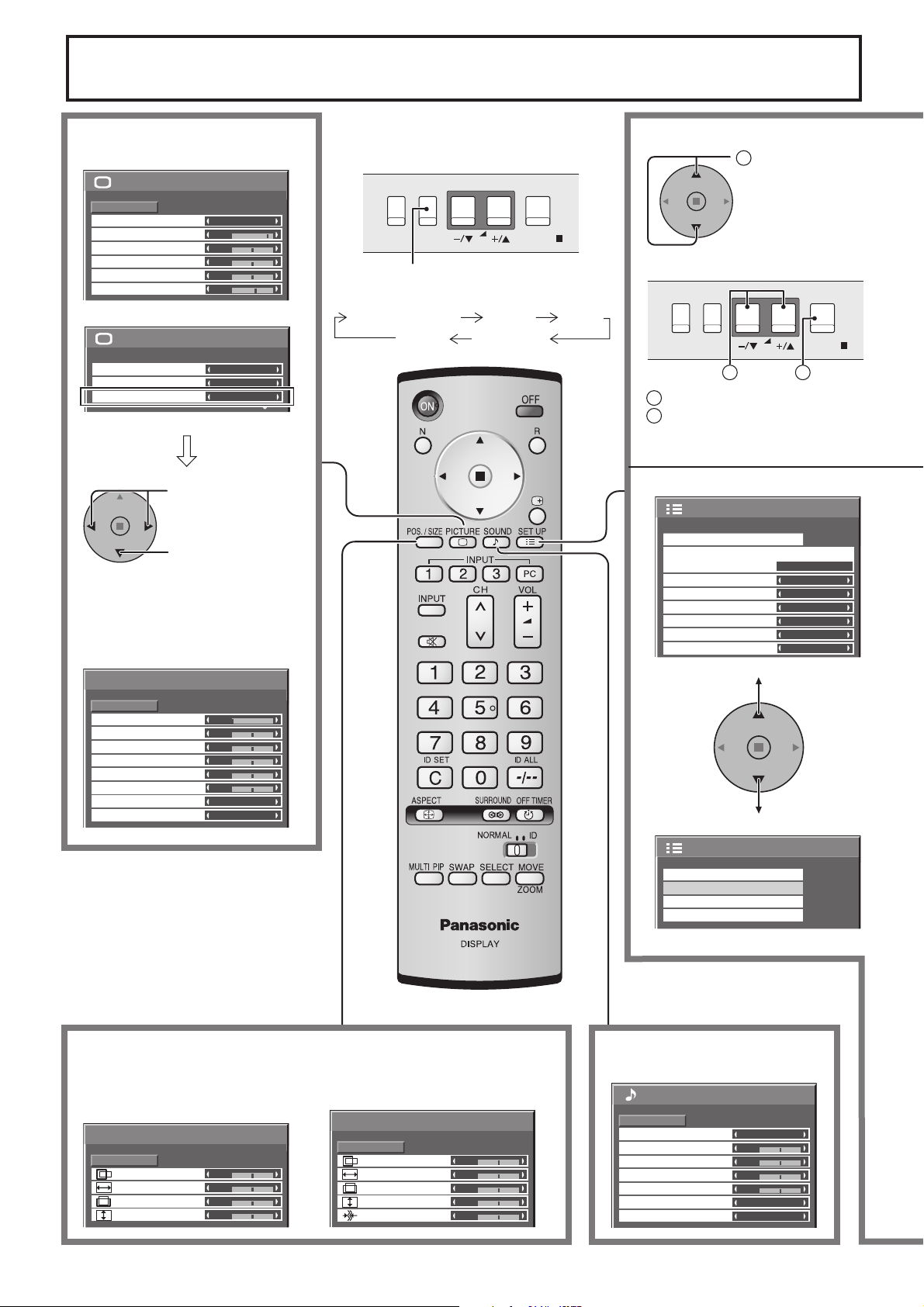
MENU
ENTER/
INPUT
VOL
On-Screen Menu Displays
To Picture adjust menu
(see page 21)
Normalise
Picture Mode
Contrast
Brightness
Colour
Tint
Sharpness
White balance
Colour Management
Advanced settings
Normal
Normal
25
0
0
0
5
Normal
Press to select
“On”.
Press to enter
Advanced settings.
To Advanced settings
(see page 21, 22)
Advanced settings
Normalise
Black extension
Input level
W/B High R
W/B High B
W/B Low R
W/B Low B
Gamma
AGC
Normal
0
0
0
0
0
0
2.2
Off
Off
On
The MENU button on the unit can also
1
be pressed.
1/2Picture
Each time the MENU button is pressed,
[ from the unit ]
Press to select.
the menu screen will switch.
Normal Viewing Picture Setup
2/2Picture
Sound Pos. /Size
MENU
INPUT
VOL
1
1
Press to select.
2
Press to access each adjust
ENTER/
2
screen.
RGB
PC
Off
Off
Off
Off
1/2
)
Setup
Signal
Component/RGB-in select
Input label
Power save
Standby save
Power management
Auto power off
OSD Language English (UK
To Pos./Size adjust menu (see page 18)
During “AV(S Video)”,
“Component” and “Digital” input
signal.
Pos. /Size
H-Pos
H-Size
V-Pos
V-Size
Normal
0
0
0
0
Normalise
14
During “RGB / PC” input signal.
Pos. /Size
Normalise
Normal
H-Pos
H-Size
V-Pos
V-Size
Clock Phase
0
0
0
0
0
Screensaver
MULTI DISPLAY Setup
Set up TIMER
PRESENT TIME Setup
To Sound adjust menu
(see page 24)
Sound
Normalise
Sound Mode
Bass
Mid
Treble
Balance
Surround
Audio Out (PIP)
Normal
0
0
0
0
2/2 Setup
Normal
Off
Main
MENU
ENTER/
INPUT
VOL
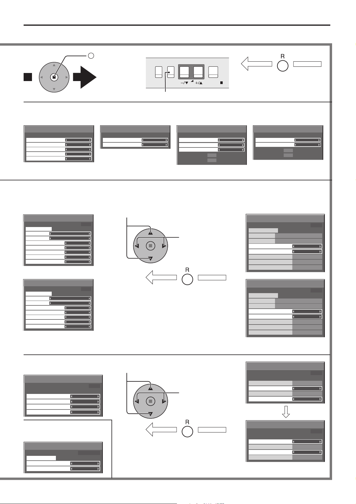
On-Screen Menu Displays
Note:
Menu that cannot be adjusted is grayout. Adjustable menu changes depending on signal, input and menu setting.
2
Press to access
[ from the unit ]
each adjust
screen.
Press the R button to return to
previous menu screen.
Press to return to next menu screen.
To Signal screen for AV
(S Video) (see page 32, 33)
On
Auto
Off
4 : 3
Off
[
Signal
3D Y/C Filter (NTSC)
Colour system
Cinema reality
Panasonic Auto (4 : 3)
P-NR
To Signal screen for
Component (see page 33)
]
AV
Signal
Cinema reality
P-NR
[
Component
Off
Off
To Signal screen for RGB
(see page 33, 34)
]
Signal
Sync
Cinema reality
P-NR
H-Freq.
V-Freq.
33.8
60.0
kHz
Hz
Auto
Off
Off
[
RGB
To Signal screen for Digital
(see page 33, 34)
]
Signal
Cinema reality
P-NR
H-Freq.
V-Freq.
Note : “Signal” setup menu displays different setting condition for each input signals. (see page 16)
Press to select Start Time / Finish Time
(When Time Designation is selected).
To setup Screensaver
(see page
Screensaver
Function
Mode
Start Time
Finish Time
Side panel
Wobbling
Peak limit
Start
28-30
)
PRESENT TIME 15:00
White bar scroll
Time Designation
6:15
12:30
High
Off
Off
Press to select Periodic Time / Operating Time
(When Interval is selected).
Press to Setup.
Screensaver
Start
Function
Mode
Start Time
Finish Time
Side panel
Wobbling
Peak limit
[
Digital
Off
Off
kHz
33.8
Hz
60.0
PRESENT TIME 15:00
White bar scroll
Time Designation
6:15
12:30
High
Off
Off
]
Screensaver
Start
Function
Mode
Periodic Time
Operating Time
Side panel
Wobbling
Peak limit
PRESENT TIME 15:00
White bar scroll
Interval
12:00
3:00
High
Off
Off
To Set up Timer selection
screen (see page 26, 27)
Set up TIMER
PRESENT TIME 10:00
POWER ON Function
POWER ON Time
POWER OFF Function
POWER OFF Time
Off
0:00
Off
0:00
To PRESENT TIME Setup
(see page 26)
PRESENT TIME Setup
PRESENT TIME MON 99:99
Set
DAY
PRESENT TIME
MON
99:99
Press the R button to return
to “Setup” menu.
Press to select POWER ON
Time / POWER OFF Time.
Press to Set up
POWER ON Time /
POWER OFF Time.
Press the R button to return
to “Setup” menu.
Screensaver
PRESENT TIME 15:00
Start
Function
Mode
Periodic Time
Operating Time
Side panel
Wobbling
Peak limit
Set up TIMER
PRESENT TIME 10:00
POWER ON Function
POWER ON Time
POWER OFF Function
POWER OFF Time
Set up TIMER
PRESENT TIME 10:00
POWER ON Function
POWER ON Time
POWER OFF Function
POWER OFF Time
White bar scroll
Interval
12:00
3:00
High
Off
Off
Off
12:00
Off
18:00
On
12:00
On
18:00
15
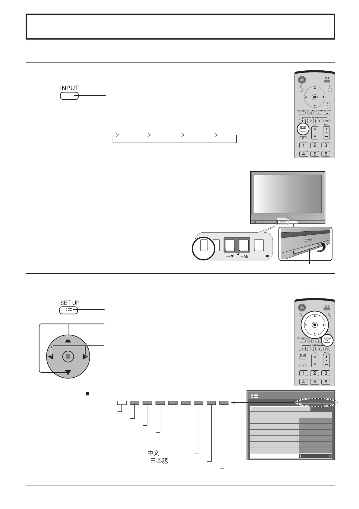
Initial selections
Selecting the input signal
Select the input signals to be connected by installing the optional Terminal Boards.
Press to select the input signal to be played back from
the equipment which has been connected to the Plasma
Display.
Input signals will change as follows:
INPUT1 INPUT2 PCINPUT3
Notes:
• Selecting is also possible by pressing the INPUT button on the unit.
• Input terminal will not be selected if the terminal board is not installed into the
SLOT.
• Select to match the signals from the source connected to the component/RGB
input terminals. (see page 32)
• In 2 screen display, the same input mode cannot be selected for the main picture
and sub picture.
MENU
INPUT
VOL
ENTER/
Swing up the door at “PULL”.
Selecting the On-Screen Menu Language
Press to display the Setup menu.
Press to select the OSD Language.
Press to select your preferred language.
Selectable languages
English(UK)
Deutsch
Français
Italiano
Español
ENGLISH(US)
.......(Chinese)
.......(Japanese)
Русский
.......(Russian)
Setup
Component/RGB-in select
Input label
Power save
Standby save
Power management
Auto power off
OSD Language English (UK
1/2
Signal
RGB
PC
Off
Off
Off
Off
)
16
 Loading...