

Page 1
ORDER NO. MTV1503368CE
Model No. TH-42C410K
Chassis: KM25
Destination: MALAYSIA
LED TV
TABLE OF CONTENTS
1 Safety Precautions ----------------------------------------------- 3
1.1. General Guidelines---------------------------------------- 3
1.1.1. Leakage Current Cold Check ---------------------- 3
1.1.2. Leakage Current Hot Check (See Figure
1.) --------------------------------------------------------- 3
2 Warning-------------------------------------------------------------- 4
2.1. Prevention of Electrostatic Discharge (ESD)
to Electrostatically Sensitive (ES) Devices---------- 4
2.2. About lead free solder (PbF)---------------------------- 5
3 Service Navigation ----------------------------------------------- 6
3.1. Service Hint ------------------------------------------------- 6
4 Specifications ----------------------------------------------------- 7
5 Service Mode ------------------------------------------------------ 8
5.1. How to enter into Service Mode ----------------------- 8
5.1.1. Purpose ------------------------------------------------- 8
5.1.2. Key command ----------------------------------------- 8
5.1.3. How to exit---------------------------------------------- 8
5.1.4. Contents of adjustment mode --------------------- 8
5.1.5. Display of SOS History ------------------------------ 9
5.1.6. Exit-------------------------------------------------------- 9
PAG E PAG E
5.1.7. Hotel Mode----------------------------------------------9
6 Troubleshooting Guide --------------------------------------- 10
6.1. Check of the IIC bus lines------------------------------ 10
6.1.1. How to access --------------------------------------- 10
6.1.2. Self-check indication only ------------------------- 10
6.1.3. Self-check indication and forced to factory
shipment setting ------------------------------------- 10
6.1.4. Exit ------------------------------------------------------ 10
6.1.5. Screen display --------------------------------------- 10
6.2. Power LED Blinking timing chart --------------------- 11
6.3. Method of detecting SOS ------------------------------ 11
6.4. LCD Panel test mode ----------------------------------- 12
6.5. No Power--------------------------------------------------- 12
7 Disassembly and Assembly Instructions--------------- 13
7.1. Speaker Fixing and Assembly ----------------------- 13
7.2. LCD Panel Fixing & Handling Method -------------- 14
7.3. Metal MTG Fixing --------------------------------------- 15
7.4. Key Button Assembly ----------------------------------- 16
7.5. PCB Fixing and Screw---------------------------------- 17
7.6. Pop Sticker & Energy Rating ------------------------- 18
© Panasonic Corporation 2015.
Page 2

TH-42C410K
7.7. Fan Bag Assembly---------------------------------------19
7.8. Pedestal Assembly -------------------------------------- 20
7.9. Back Cover ------------------------------------------------ 21
7.10. Back Cover - Label & Screw -------------------------- 22
8 Measurements and Adjustments -------------------------- 23
8.1. Voltage chart of A-board-------------------------------- 23
8.2. Voltage chart of P-board-------------------------------- 23
9 Block Diagram --------------------------------------------------- 24
9.1. Main Block Diagram ------------------------------------- 24
10 Wiring Connection Diagram --------------------------------- 25
10.1. Wire Dressing 1------------------------------------------- 25
10.2. Wire Dressing 2------------------------------------------- 26
11 Schematic Diagram--------------------------------------------- 27
12 Printed Circuit Board ------------------------------------------ 46
13 Exploded View and Replacement Parts List -----------53
2
Page 3
TH-42C410K
1 Safety Precautions
1.1. General Guidelines
1. When servicing, observe the original lead dress. If a short circuit is found, replace all parts which have been overheated or
damaged by the short circuit.
2. After servicing, see to it that all the protective devices such as insulation barriers, insulation papers shields are properly
installed.
3. After servicing, make the following leakage current checks to prevent the customer from being exposed to shock hazards.
4. When conducting repairs and servicing, do not attempt to modify the equipment, its parts or its materials.
5. When wiring units (with cables, flexible cables or lead wires) are supplied as repair parts and only one wire or some of the
wires have been broken or disconnected, do not attempt to repair or re-wire the units. Replace the entire wiring unit instead.
6. When conducting repairs and servicing, do not twist the Faston connectors but plug them straight in or unplug them straight
out.
1.1.1. Leakage Current Cold Check
1. Unplug the AC cord and connect a jumper between the
two prongs on the plug.
2. Measure the resistance value, with an ohmmeter,
between the jumpered AC plug and each exposed
metallic cabinet part on the equipment such as
screwheads, connectors, control shafts, etc. When the
exposed metallic part has a return path to the chassis, the
reading should be 8.5Mohm to 13Mohm.
When the exposed metal does not have a return path to
the chassis, the reading must be .
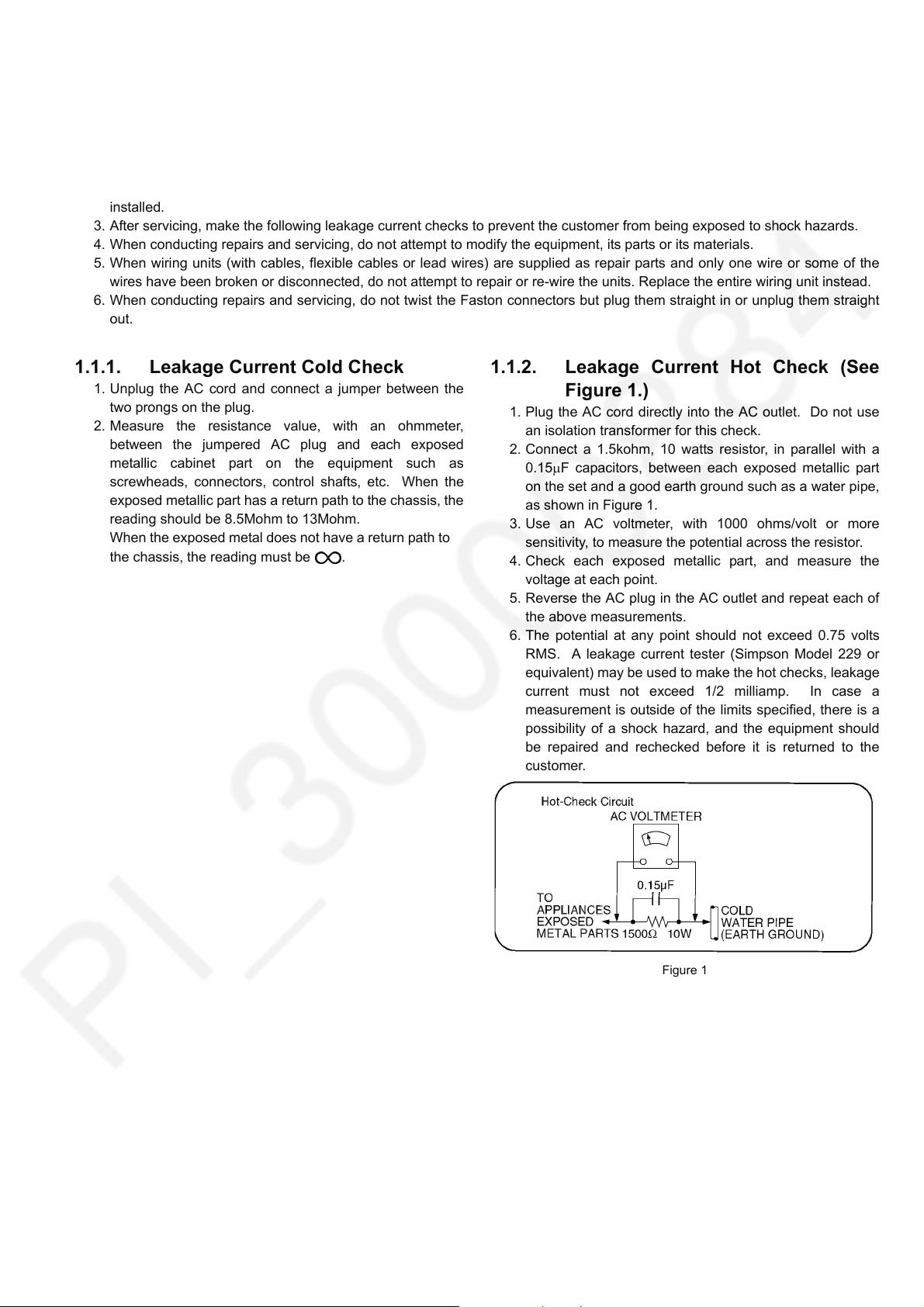
1.1.2. Leakage Current Hot Check (See Figure 1.)
1. Plug the AC cord directly into the AC outlet. Do not use
an isolation transformer for this check.
2. Connect a 1.5kohm, 10 watts resistor, in parallel with a
0.15F capacitors, between each exposed metallic part
on the set and a good earth ground such as a water pipe,
as shown in Figure 1.
3. Use an AC voltmeter, with 1000 ohms/volt or more
sensitivity, to measure the potential across the resistor.
4. Check each exposed metallic part, and measure the
voltage at each point.
5. Reverse the AC plug in the AC outlet and repeat each of
the above measurements.
6. The potential at any point should not exceed 0.75 volts
RMS. A leakage current tester (Simpson Model 229 or
equivalent) may be used to make the hot checks, leakage
current must not exceed 1/2 milliamp. In case a
measurement is outside of the limits specified, there is a
possibility of a shock hazard, and the equipment should
be repaired and rechecked before it is returned to the
customer.
Figure 1
3
Page 4
TH-42C410K
2Warning
2.1. Prevention of Electrostatic Discharge (ESD) to Electrostatically Sensitive (ES) Devices
Some semiconductor (solid state) devices can be damaged easily by static electricity. Such components commonly are called
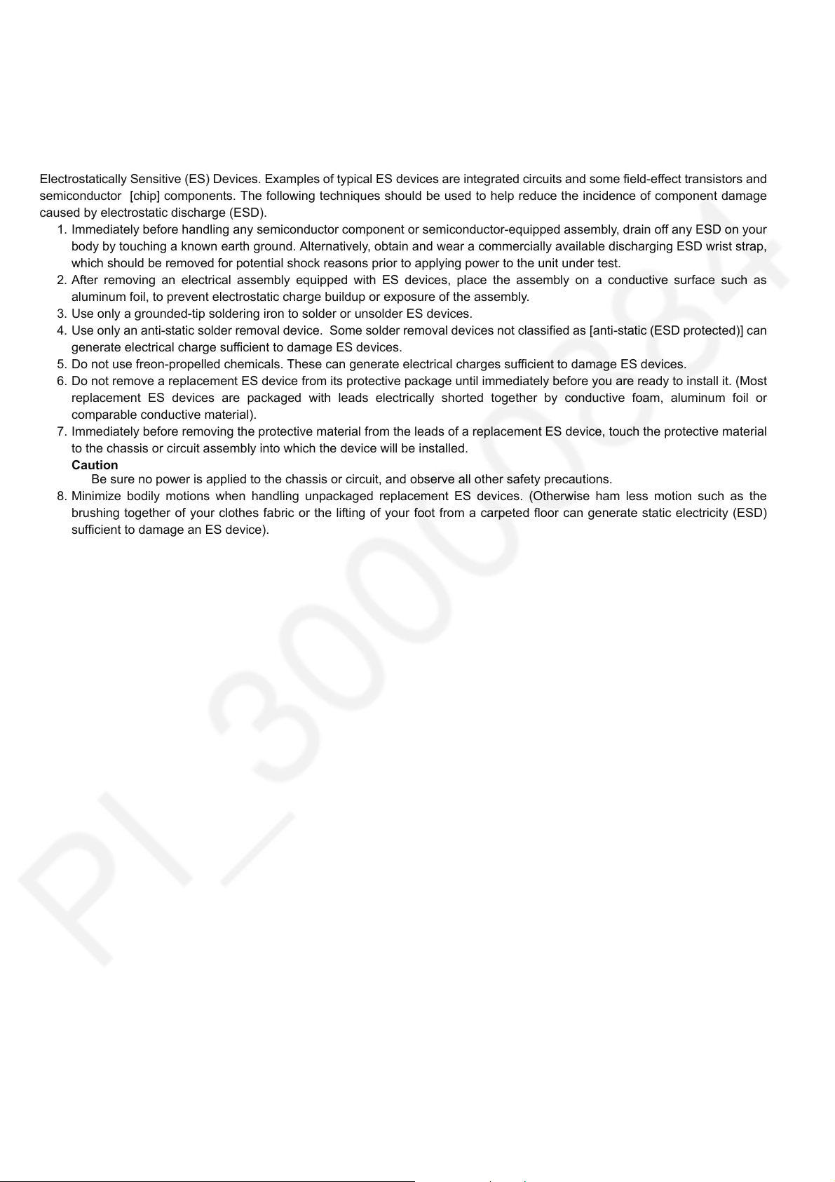
Electrostatically Sensitive (ES) Devices. Examples of typical ES devices are integrated circuits and some field-effect transistors and
semiconductor [chip] components. The following techniques should be used to help reduce the incidence of component damage
caused by electrostatic discharge (ESD).
1. Immediately before handling any semiconductor component or semiconductor-equipped assembly, drain off any ESD on your
body by touching a known earth ground. Alternatively, obtain and wear a commercially available discharging ESD wrist strap,
which should be removed for potential shock reasons prior to applying power to the unit under test.
2. After removing an electrical assembly equipped with ES devices, place the assembly on a conductive surface such as
aluminum foil, to prevent electrostatic charge buildup or exposure of the assembly.
3. Use only a grounded-tip soldering iron to solder or unsolder ES devices.
4. Use only an anti-static solder removal device. Some solder removal devices not classified as [anti-static (ESD protected)] can
generate electrical charge sufficient to damage ES devices.
5. Do not use freon-propelled chemicals. These can generate electrical charges sufficient to damage ES devices.
6. Do not remove a replacement ES device from its protective package until immediately before you are ready to install it. (Most
replacement ES devices are packaged with leads electrically shorted together by conductive foam, aluminum foil or
comparable conductive material).
7. Immediately before removing the protective material from the leads of a replacement ES device, touch the protective material
to the chassis or circuit assembly into which the device will be installed.
Caution
Be sure no power is applied to the chassis or circuit, and observe all other safety precautions.
8. Minimize bodily motions when handling unpackaged replacement ES devices. (Otherwise ham less motion such as the
brushing together of your clothes fabric or the lifting of your foot from a carpeted floor can generate static electricity (ESD)
sufficient to damage an ES device).
4
Page 5
TH-42C410K
2.2. About lead free solder (PbF)
Note: Lead is listed as (Pb) in the periodic table of elements.
In the information below, Pb will refer to Lead solder, and PbF will refer to Lead Free Solder.
The Lead Free Solder used in our manufacturing process and discussed below is (Sn+Ag+Cu).
That is Tin (Sn), Silver (Ag) and Copper (Cu) although other types are available.
This model uses Pb Free solder in it’s manufacture due to environmental conservation issues. For service and repair work, we’d
suggest the use of Pb free solder as well, although Pb solder may be used.
PCBs manufactured using lead free solder will have the PbF within a leaf Symbol PbF stamped on the back of PCB.
Caution
• Pb free solder has a higher melting point than standard solder. Typically the melting point is 50 ~ 70 °F (30~40 °C) higher. Please
use a high temperature soldering iron and set it to 700 ± 20 °F (370 ± 10 °C).
• Pb free solder will tend to splash when heated too high (about 1100 °F or 600 °C).
If you must use Pb solder, please completely remove all of the Pb free solder on the pins or solder area before applying Pb
solder. If this is not practical, be sure to heat the Pb free solder until it melts, before applying Pb solder.
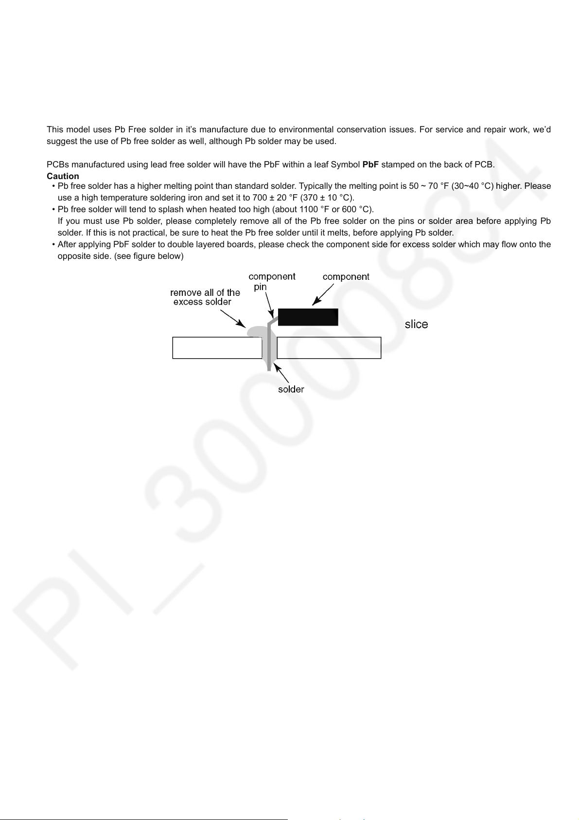
• After applying PbF solder to double layered boards, please check the component side for excess solder which may flow onto the
opposite side. (see figure below)
5
Page 6
TH-42C410K
3 Service Navigation
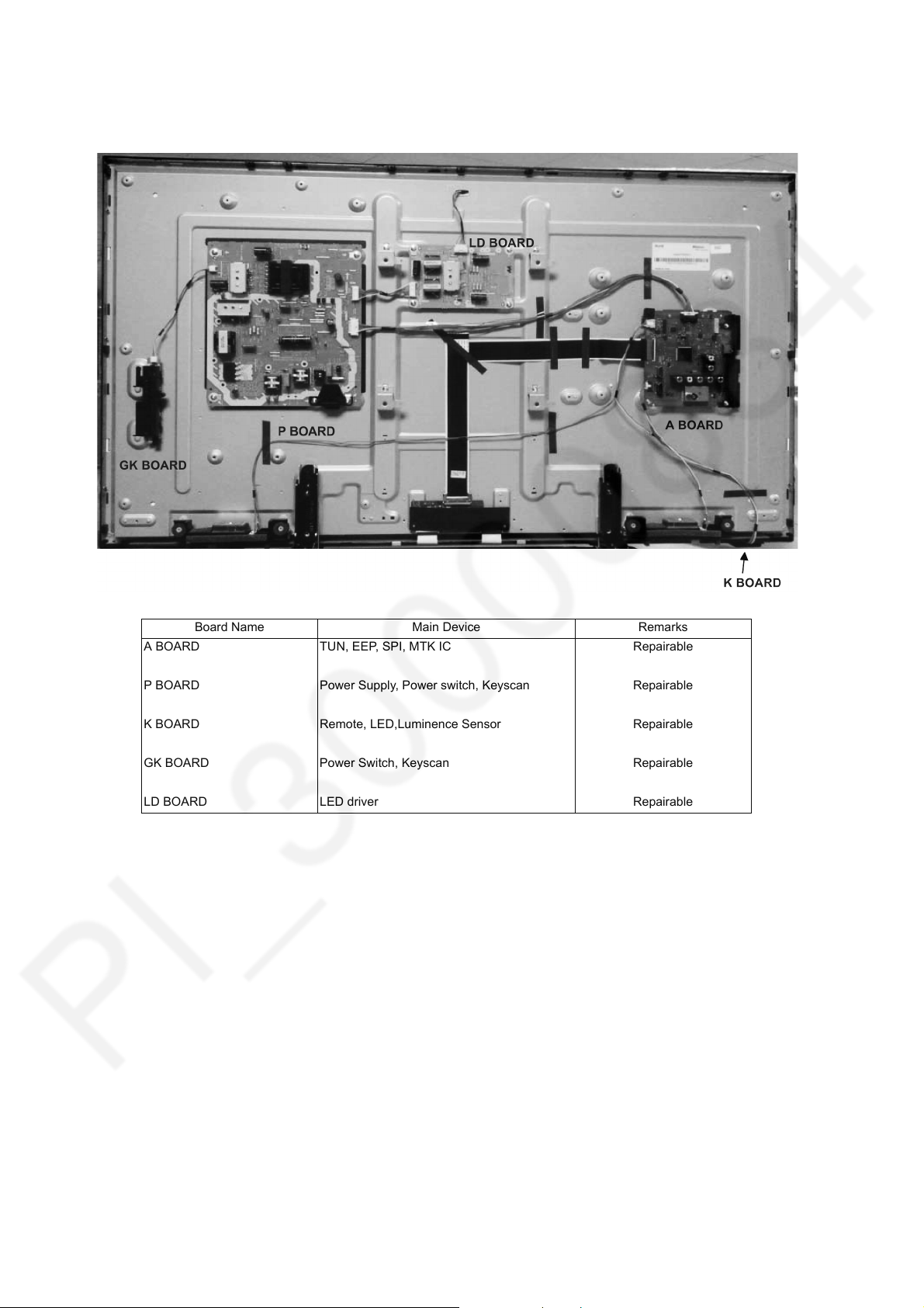
3.1. Service Hint
Board Name Main Device Remarks
A BOARD TUN, EEP, SPI, MTK IC Repairable
P BOARD Power Supply, Power switch, Keyscan Repairable
K BOARD Remote, LED,Luminence Sensor Repairable
GK BOARD Power Switch, Keyscan Repairable
LD BOARD LED driver Repairable
6
Page 7
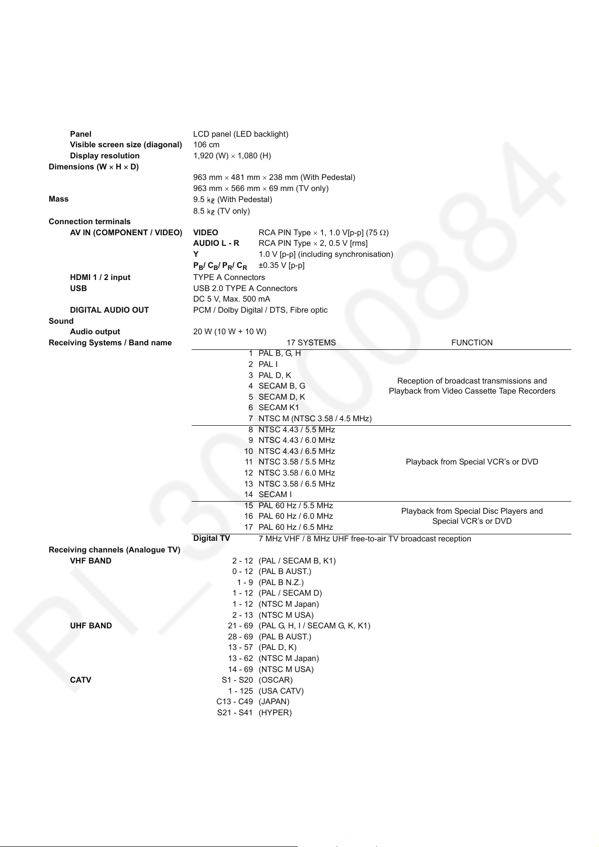
4 Specifications
Power Source AC 220-240 V, 50/60 Hz
Power consumption
(Rated power / Standby power) 89 W / 0.35 W
Display panel
Panel LCD panel (LED backlight)
Visible screen size (diagonal) 106 cm
Display resolution 1,920 (W) 1,080 (H)
Dimensions (W H D)
963 mm 481 mm 238 mm (With Pedestal)
963 mm 566 mm 69 mm (TV only)
Mass
Connection terminals
AV IN (COMPONENT / VIDEO) VIDEO RCA PIN Type 1, 1.0 V[p-p] (75 )
HDMI 1 / 2 input TYPE A Connectors
USB USB 2.0 TYPE A Connectors
DIGITAL AUDIO OUT PCM / Dolby Digital / DTS, Fibre optic
Sound
Audio output 20 W (10 W + 10 W)
Receiving Systems / Band name 17 SYSTEMS FUNCTION
Receiving channels (Analogue TV)
VHF BAND 2 - 12 (PAL / SECAM B, K1)
UHF BAND 21 - 69 (PAL G, H, I / SECAM G, K, K1)
CATV S1 - S20 (OSCAR)
Aerial input VHF / UHF
Operating Conditions Temperature : 0°C - 40°C
Note
• Design and Specifications are subject to change without notice. Mass and Dimensions shown are approximate.
9.5 (With Pedestal)
8.5 (TV only)
AUDIO L - R RCA PIN Type 2, 0.5 V [rms]
Y 1.0 V [p-p] (including synchronisation)
P
/ CB/ PR/ CR±0.35 V [p-p]
B
DC 5 V, Max. 500 mA
1 PAL B, G, H
2PAL I
3PAL D, K
4 SECAM B, G
5SECAM D, K
6 SECAM K1
7
NTSC M (NTSC 3.58 / 4.5 MHz)
8 NTSC 4.43 / 5.5 MHz
9 NTSC 4.43 / 6.0 MHz
10 NTSC 4.43 / 6.5 MHz
11 NTSC 3.58 / 5.5 MHz
12 NTSC 3.58 / 6.0 MHz
13 NTSC 3.58 / 6.5 MHz
14 SECAM I
15 PAL 60 Hz / 5.5 MHz
16 PAL 60 Hz / 6.0 MHz
17 PAL 60 Hz / 6.5 MHz
Digital TV
28 - 69 (PAL B AUST.)
13 - 57 (PAL D, K)
13 - 62 (NTSC M Japan)
14 - 69 (NTSC M USA)
1 - 125 (USA CATV)
C13 - C49 (JAPAN)
S21 - S41 (HYPER)
Z1 - Z37 (CHINA)
Humidity : 20 % - 80 % RH (non-condensing)
7 MHz VHF / 8 MHz UHF free-to-air TV broadcast reception
0 - 12 (PAL B AUST.)
1 - 9 (PAL B N.Z.)
1 - 12 (PAL / SECAM D)
1 - 12 (NTSC M Japan)
2 - 13 (NTSC M USA)
5A, 9A (AUST.)
Reception of broadcast transmissions and
Playback from Video Cassette Tape Recorders
Playback from Special VCR’s or DVD
Playback from Special Disc Players and
Special VCR’s or DVD
TH-42C410K
7
Page 8
TH-42C410K
5 Service Mode
5.1. How to enter into Service Mode
5.1.1. Purpose
After exchange parts, check and adjust the contents of adjustment mode.
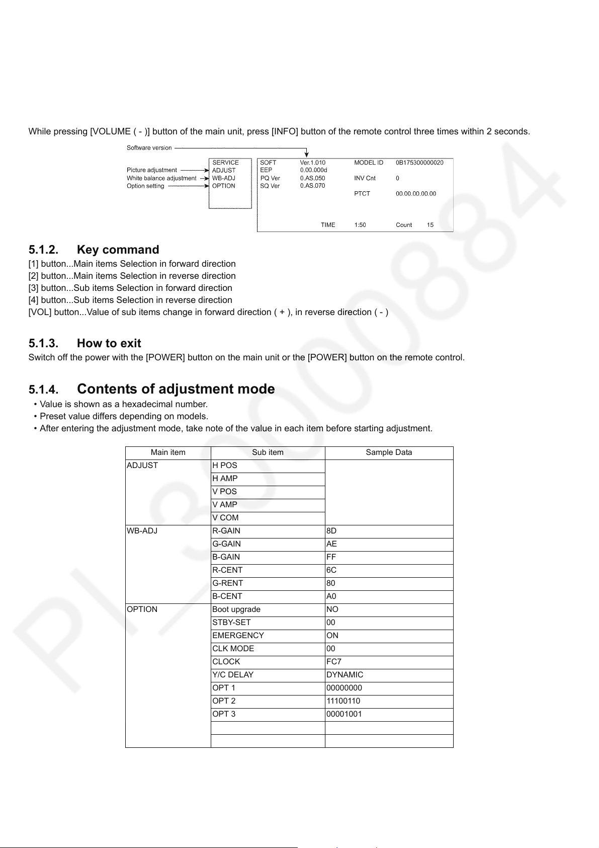
While pressing [VOLUME ( - )] button of the main unit, press [INFO] button of the remote control three times within 2 seconds.
5.1.2. Key command
[1] button...Main items Selection in forward direction
[2] button...Main items Selection in reverse direction
[3] button...Sub items Selection in forward direction
[4] button...Sub items Selection in reverse direction
[VOL] button...Value of sub items change in forward direction ( + ), in reverse direction ( - )
5.1.3. How to exit
Switch off the power with the [POWER] button on the main unit or the [POWER] button on the remote control.
5.1.4. Contents of adjustment mode
• Value is shown as a hexadecimal number.
• Preset value differs depending on models.
• After entering the adjustment mode, take note of the value in each item before starting adjustment.
Main item Sub item Sample Data
ADJUST H POS
H AMP
V POS
V AMP
V COM
WB-ADJ R-GAIN 8D
G-GAIN AE
B-GAIN FF
R-CENT 6C
G-RENT 80
B-CENT A0
OPTION Boot upgrade NO
STBY-SET 00
EMERGENCY ON
CLK MODE 00
CLOCK FC7
Y/C DELAY DYNAMIC
OPT 1 00000000
OPT 2 11100110
OPT 3 00001001
OPT 4 00000000
EDID-CLK HIGH
8
Page 9
TH-42C410K
5.1.5. Display of SOS History
SOS History (Number of LED blinking) indication.
From left side; Last SOS, before Last, three occurrence before, 2nd occurrence after shipment, 1st occurrence after shipment.
This indication except 2nd and 1st occurrence after shipment will be cleared by [Self-check indication and forced to factory
shipment setting].
5.1.6. Exit
1. Disconnect the AC cord from wall outlet.
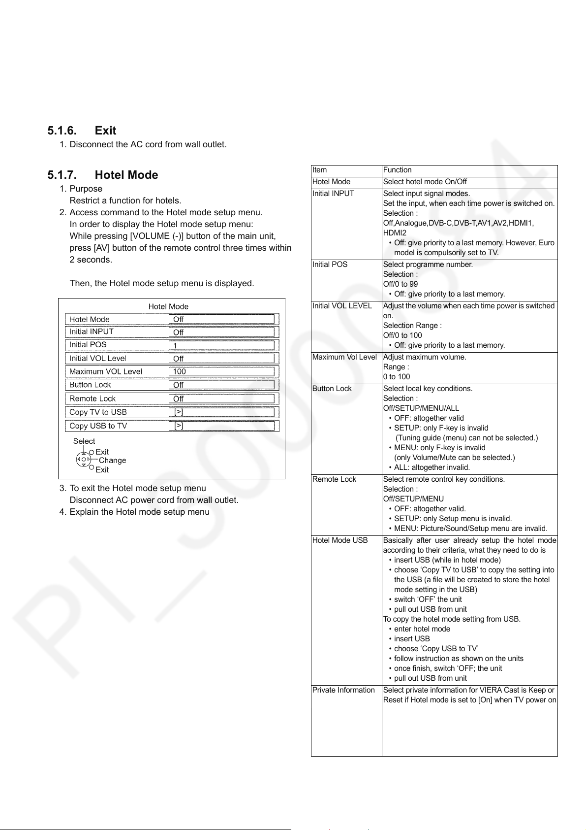
5.1.7. Hotel Mode
1. Purpose
Restrict a function for hotels.
2. Access command to the Hotel mode setup menu.
In order to display the Hotel mode setup menu:
While pressing [VOLUME (-)] button of the main unit,
press [AV] button of the remote control three times within
2 seconds.
Then, the Hotel mode setup menu is displayed.
3. To exit the Hotel mode setup menu
Disconnect AC power cord from wall outlet.
4. Explain the Hotel mode setup menu
Item Function
Hotel Mode Select hotel mode On/Off
Initial INPUT Select input signal modes.
Set the input, when each time power is switched on.
Selection :
Off,Analogue,DVB-C,DVB-T,AV1,AV2,HDMI1,
HDMI2
• Off: give priority to a last memory. However, Euro
model is compulsorily set to TV.
Initial POS Select programme number.
Selection :
Off/0 to 99
• Off: give priority to a last memory.
Initial VOL LEVEL Adjust the volume when each time power is switched
on.
Selection Range :
Off/0 to 100
• Off: give priority to a last memory.
Maximum Vol Level Adjust maximum volume.
Range :
0 to 100
Button Lock Select local key conditions.
Selection :
Off/SETUP/MENU/ALL
• OFF: altogether valid
• SETUP: only F-key is invalid
(Tuning guide (menu) can not be selected.)
• MENU: only F-key is invalid
(only Volume/Mute can be selected.)
• ALL: altogether invalid.
Remote Lock Select remote control key conditions.
Selection :
Off/SETUP/MENU
• OFF: altogether valid.
• SETUP: only Setup menu is invalid.
• MENU: Picture/Sound/Setup menu are invalid.
Hotel Mode USB Basically after user already setup the hotel mode
according to their criteria, what they need to do is
• insert USB (while in hotel mode)
• choose ‘Copy TV to USB’ to copy the setting into
the USB (a file will be created to store the hotel
mode setting in the USB)
• switch ‘OFF’ the unit
• pull out USB from unit
To copy the hotel mode setting from USB.
• enter hotel mode
•insert USB
• choose ‘Copy USB to TV’
• follow instruction as shown on the units
• once finish, switch ‘OFF; the unit
• pull out USB from unit
Private Information Select private information for VIERA Cast is Keep or
Reset if Hotel mode is set to [On] when TV power on
Selection :
Keep/Reset
• Keep: private information for VIERA Cast is keep
• Reset: private information for VIERA Cast is
reset
9
Page 10
TH-42C410K
6 Troubleshooting Guide
Use the self-check function to test the unit.
1. Checking the IIC bus lines
2. Power LED Blinking timing
6.1. Check of the IIC bus lines
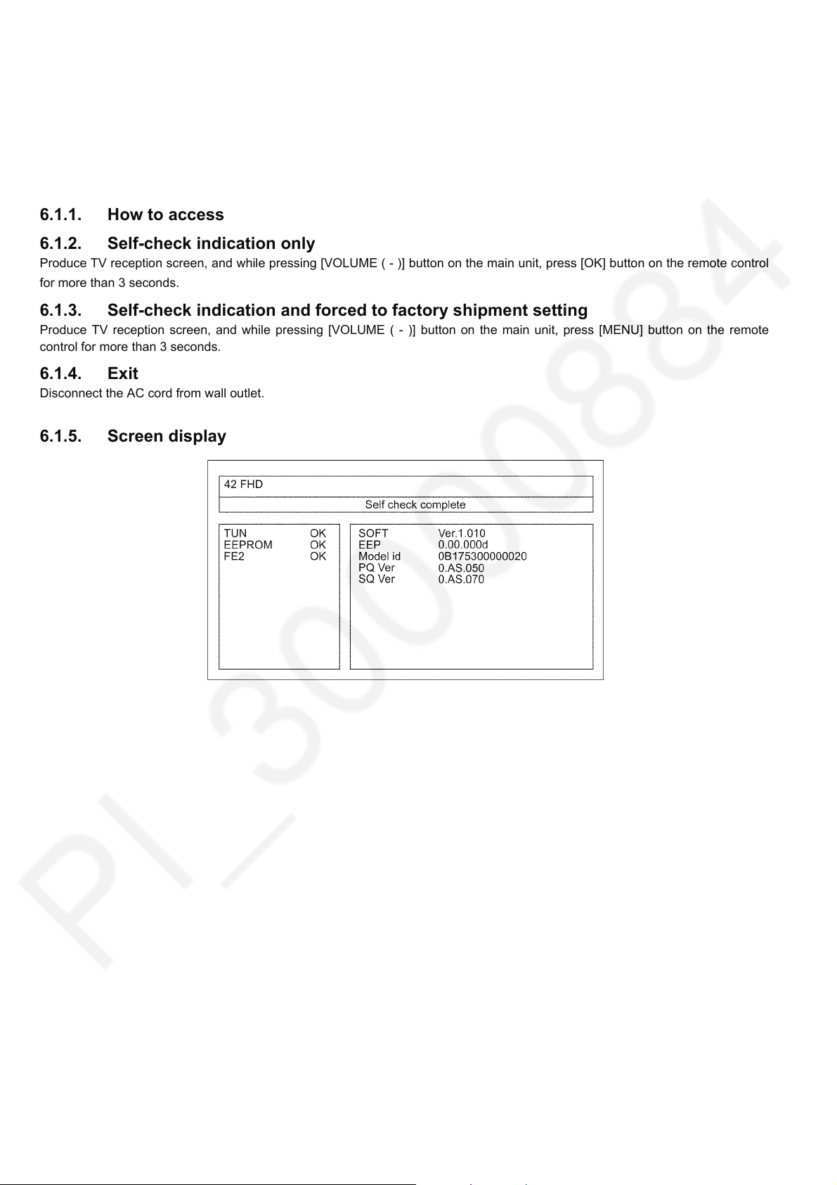
6.1.1. How to access
6.1.2. Self-check indication only
Produce TV reception screen, and while pressing [VOLUME ( - )] button on the main unit, press [OK] button on the remote control
for more than 3 seconds.
6.1.3. Self-check indication and forced to factory shipment setting
Produce TV reception screen, and while pressing [VOLUME ( - )] button on the main unit, press [MENU] button on the remote
control for more than 3 seconds.
6.1.4. Exit
Disconnect the AC cord from wall outlet.
6.1.5. Screen display
10
Page 11
6.2. Power LED Blinking timing chart
1. Subject
Information of LED Flashing timing chart.
2. Contents
When an abnormality occurs, the protection circuit will operate and reset the unit to stand by mode. During this time, the
defective block can be identified by the number of blinking times of the Power LED on the front panel of the unit as follow:
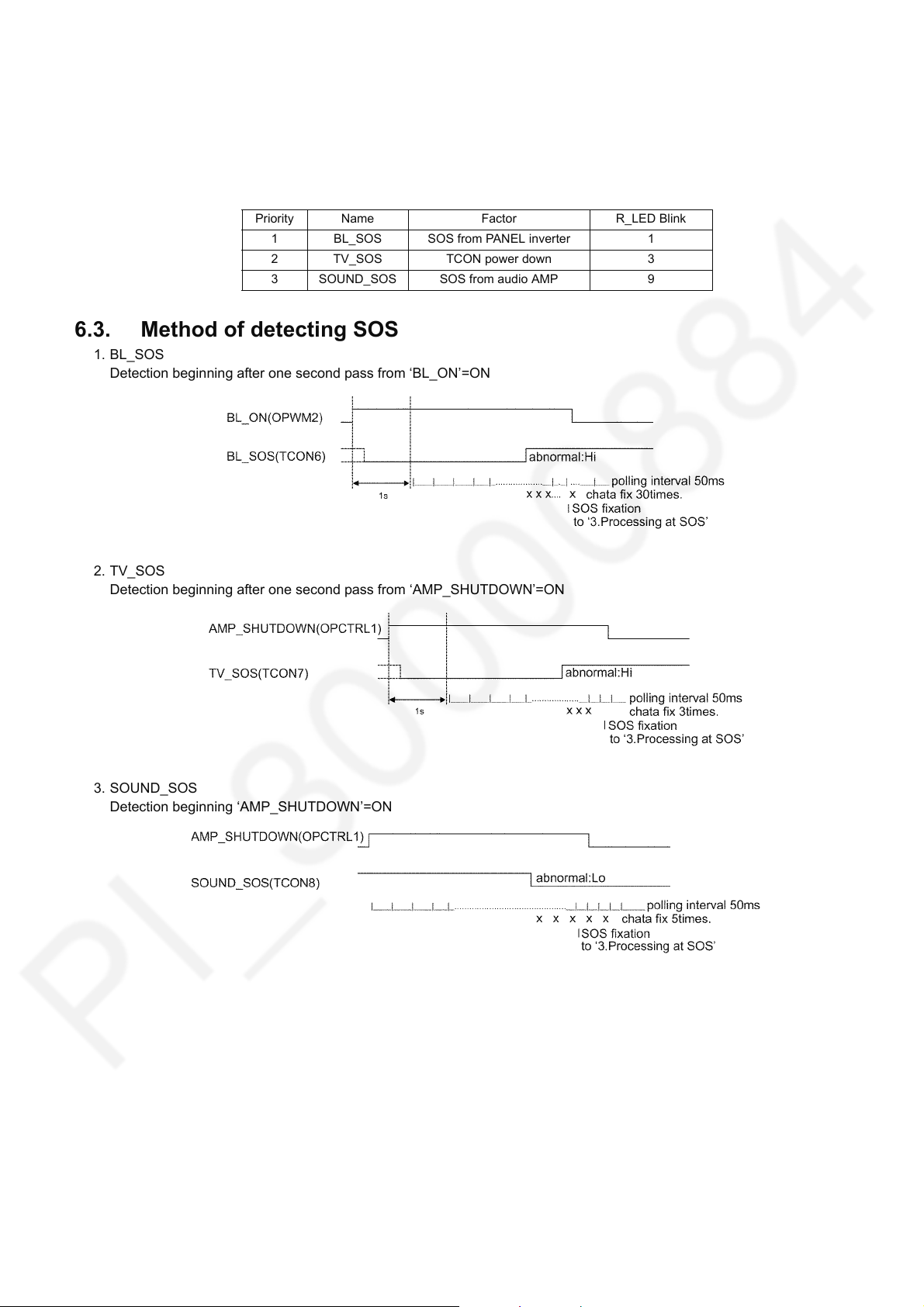
Priority Name Factor R_LED Blink
1 BL_SOS SOS from PANEL inverter 1
2 TV_SOS TCON power down 3
3 SOUND_SOS SOS from audio AMP 9
6.3. Method of detecting SOS
1. BL_SOS
Detection beginning after one second pass from ‘BL_ON’=ON
TH-42C410K
2. TV_SOS
Detection beginning after one second pass from ‘AMP_SHUTDOWN’=ON
3. SOUND_SOS
Detection beginning ‘AMP_SHUTDOWN’=ON
11
Page 12
TH-42C410K
6.4. LCD Panel test mode
Purpose:
To find the possible failure point where in LCD Panel or Printed Circuit Board when the abnormal picture is displayed.
How to Enter:
While pressing [VOLUME ( - )] button of the main unit, press [OPTION] button of the remote control three times within 2
seconds.
How to Exit:
Disconnect AC plug from wall outlet.
How to confirm:
If the abnormal picture is displayed, go into LCD Panel test mode to display the several test patterns.
And then, judge by the following method.
Still abnormal picture is displayed: The cause must be in LCD Panel.
Normal picture is displayed: The cause must be in A board.
Remarks:
The test pattern is created by the circuit in LCD Panel.
In LCD Panel test mode, this test pattern is displayed unaffected by signal processing for RF or input signal.
If the normal picture is displayed, LCD Panel must be okay and the cause of failure must be in A board.
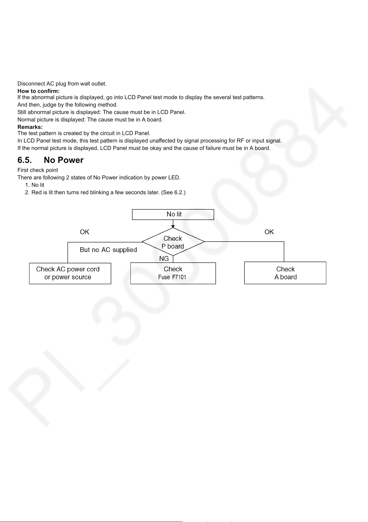
6.5. No Power
First check point
There are following 2 states of No Power indication by power LED.
1. No lit
2. Red is lit then turns red blinking a few seconds later. (See 6.2.)
12
Page 13
7 Disassembly and Assembly Instructions
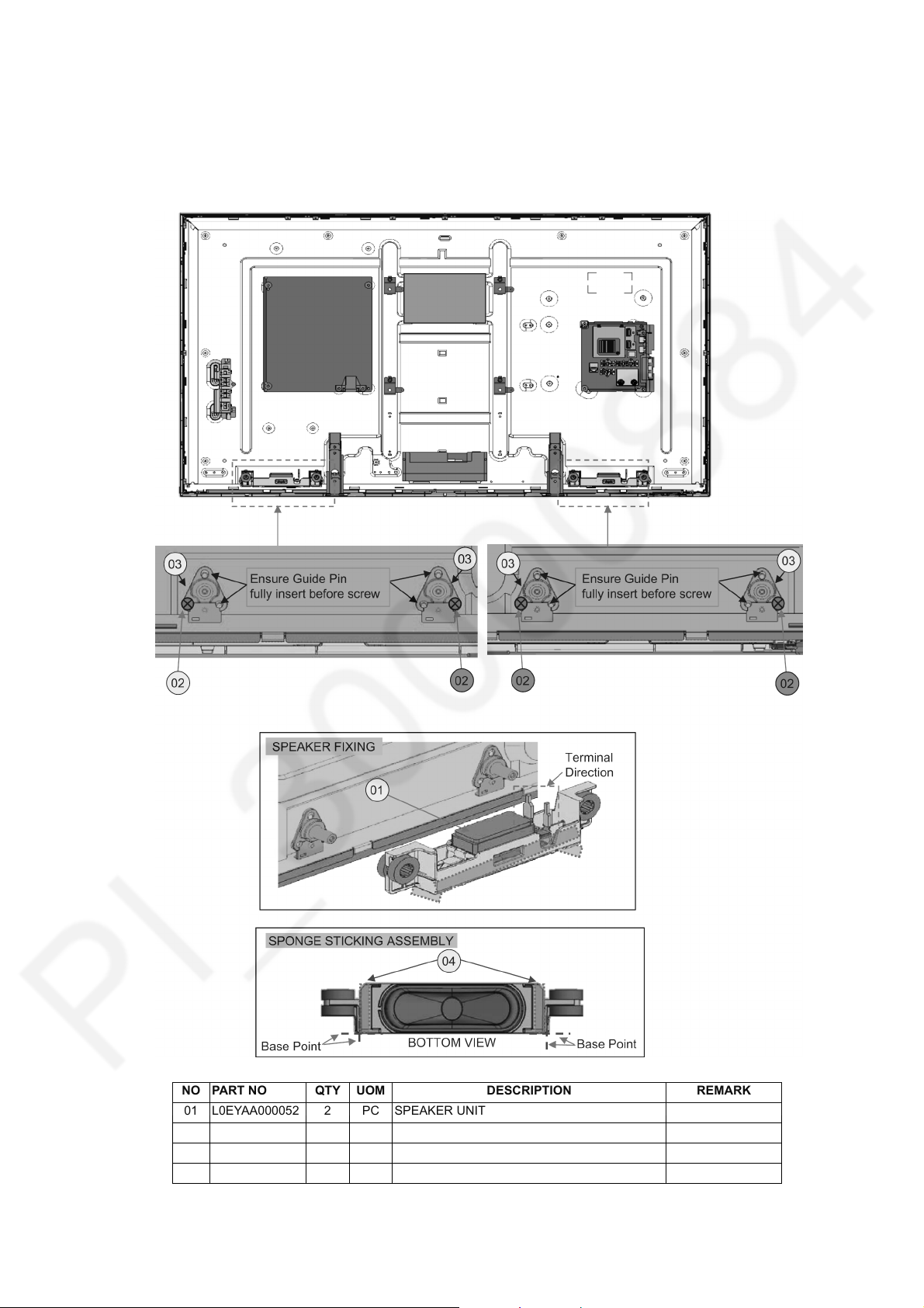
7.1. Speaker Fixing and Assembly
1. Fix speaker bracket at panel and screw.
2. Stick sponge at speaker and slot at speaker bracket.
TH-42C410K
NO PART NO QTY UOM DESCRIPTION REMARK
01 L0EYAA000052 2 PC SPEAKER UNIT
02 THEJ036J 4 PC SCREW (A3/P5/VESA4/MTL4/LBRD4/SP4) 06 ± 1 Kgf.cm
03 TKP5ZA41901 4 PC SP BRACKET
04 TMK4GG100 4 PC SP. SPONGE
13
Page 14
TH-42C410K
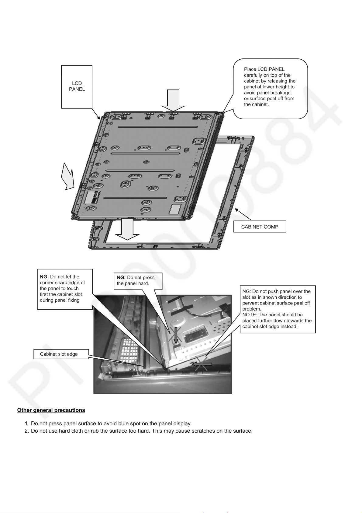
7.2. LCD Panel Fixing & Handling Method
1. Place down the cabinet as shown below.
2. Fix LCD panel into the cabinet by taking below precautions.
Other general precautions
1. Do not press panel surface to avoid blue spot on the panel display.
2. Do not use hard cloth or rub the surface too hard. This may cause scratches on the surface.
3. Take care not to subject the TV’s surface to water or detergent. Any liquid (including pets urine) if enters the product could
lead to TV failure.
4. Take care not to subject the surface to insect repellent, solvent, thiner or other voiltile substances. This may degrade surface
quality or cause peeling of the paint.
5. The surface of the display panel is specially treated and may be easily damaged. Take care not to tap or scratch with your
fingernail or other hard objects.
14
Page 15
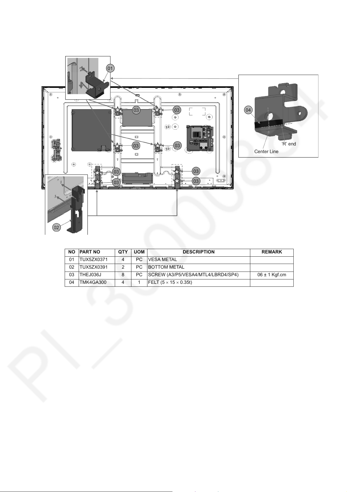
7.3. Metal MTG Fixing
Fix vesa metal and bottom panel into panel and screw.
TH-42C410K
NO PART NO QTY UOM DESCRIPTION REMARK
01 TUX5ZX0371 4 PC VESA METAL
02 TUX5ZX0391 2 PC BOTTOM METAL
03 THEJ036J 8 PC SCREW (A3/P5/VESA4/MTL4/LBRD4/SP4) 06 ± 1 Kgf.cm
04 TMK4GA300 4 1 FELT (5 15 0.35t)
15
Page 16
TH-42C410K
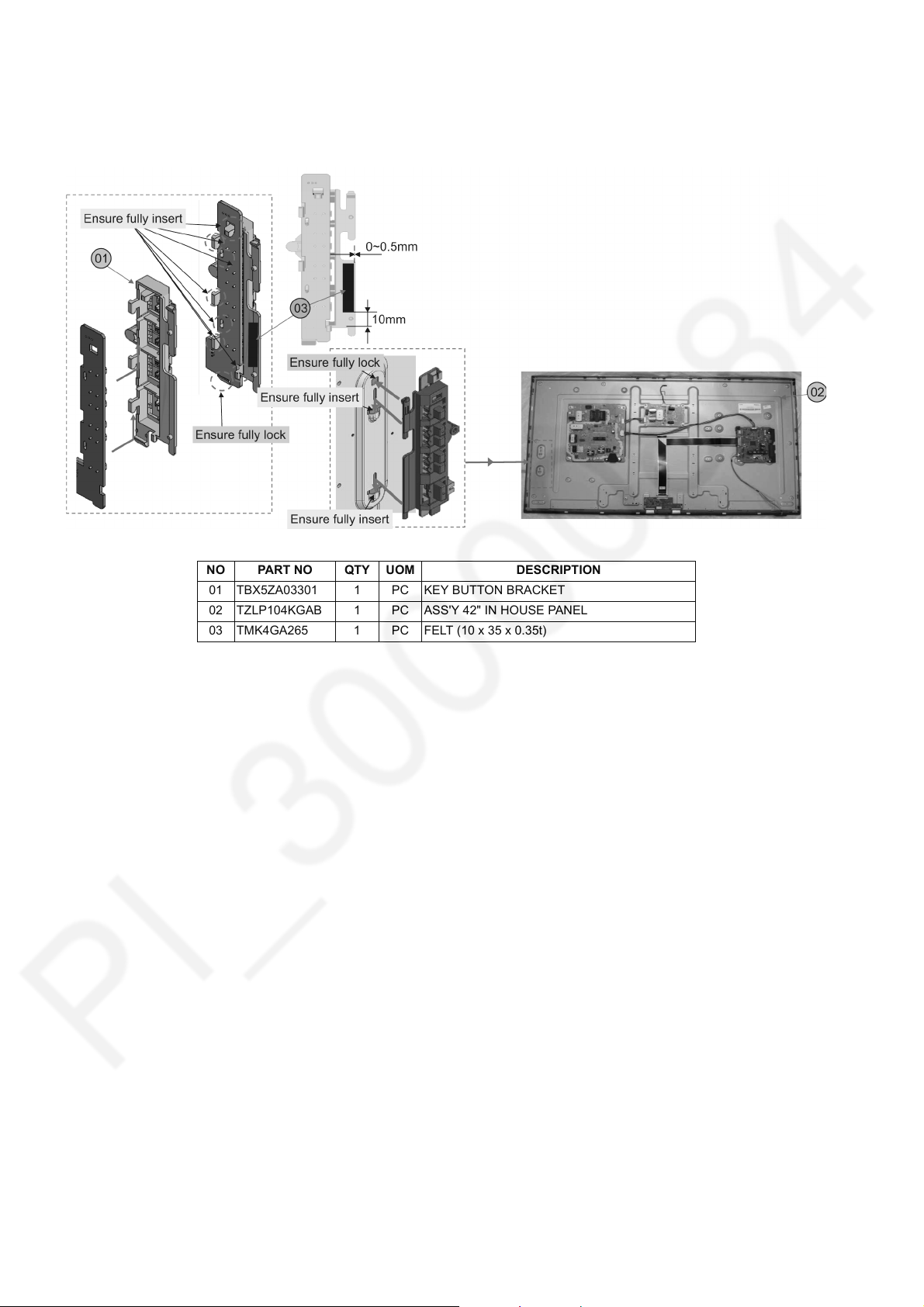
7.4. Key Button Assembly
Fix pcb at key button bracket and fix at panel.
NO PART NO QTY UOM DESCRIPTION
01 TBX5ZA03301 1 PC KEY BUTTON BRACKET
02 TZLP104KGAB 1 PC ASS'Y 42" IN HOUSE PANEL
03 TMK4GA265 1 PC FELT (10 x 35 x 0.35t)
16
Page 17
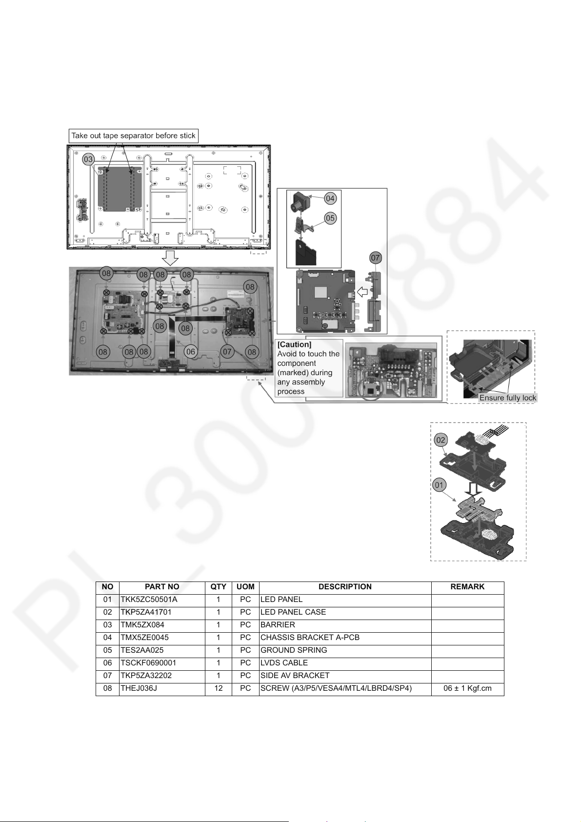
7.5. PCB Fixing and Screw
1. Stick barrier at panel.
2. Assembly led panel.
3. Fix chassis bracket, ground spring and side av bracket at pcb.
4. Fix all pcb and screw.
TH-42C410K
NO PART NO QTY UOM DESCRIPTION REMARK
01 TKK5ZC50501A 1 PC LED PANEL
02 TKP5ZA41701 1 PC LED PANEL CASE
03 TMK5ZX084 1 PC BARRIER
04 TMX5ZE0045 1 PC CHASSIS BRACKET A-PCB
05 TES2AA025 1 PC GROUND SPRING
06 TSCKF0690001 1 PC LVDS CABLE
07 TKP5ZA32202 1 PC SIDE AV BRACKET
08 THEJ036J 12 PC SCREW (A3/P5/VESA4/MTL4/LBRD4/SP4) 06 ± 1 Kgf.cm
17
Page 18
TH-42C410K
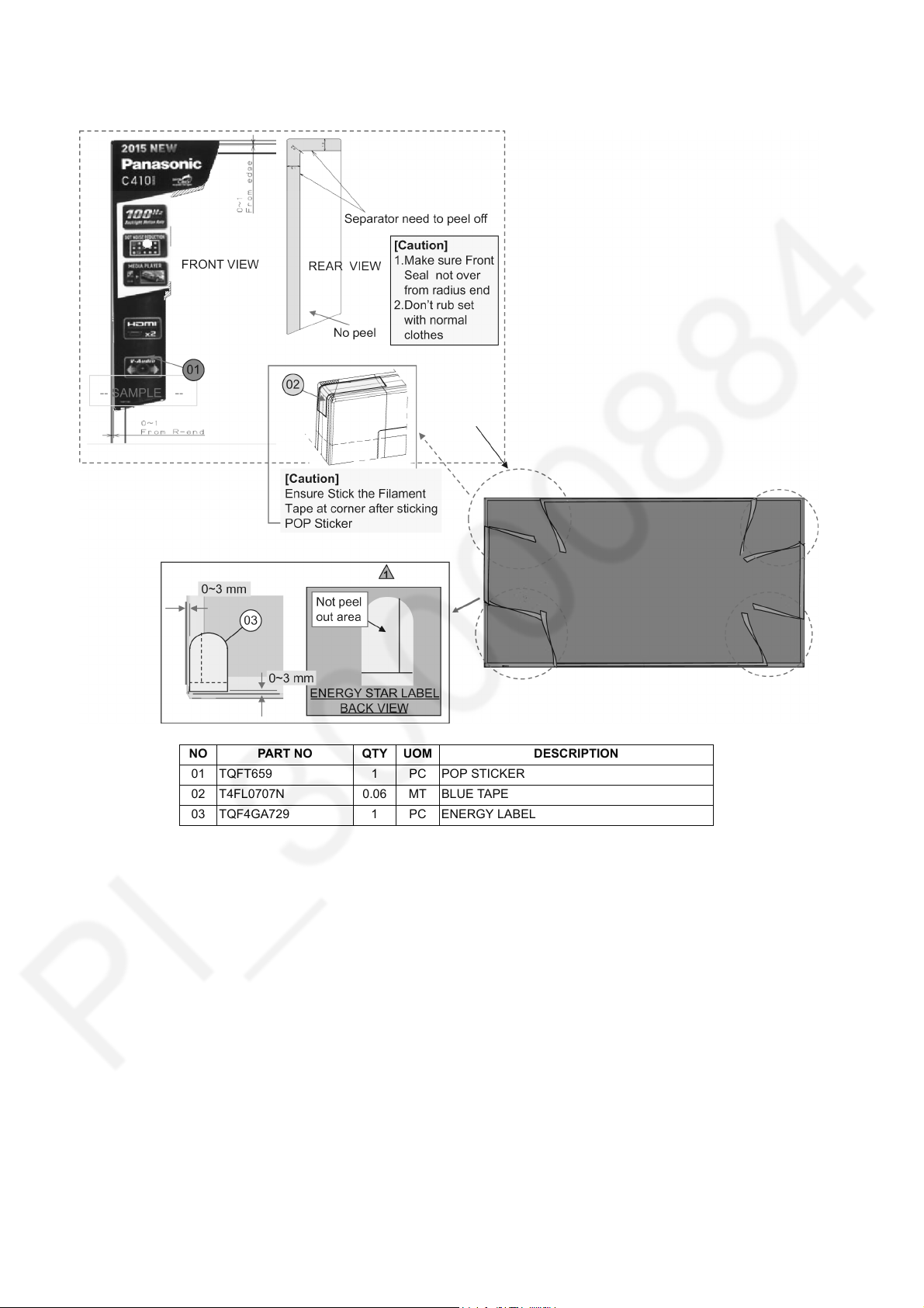
7.6. Pop Sticker & Energy Rating
NO PART NO QTY UOM DESCRIPTION
01 TQFT659 1 PC POP STICKER
02 T4FL0707N 0.06 MT BLUE TAPE
03 TQF4GA729 1 PC ENERGY LABEL
18
Page 19
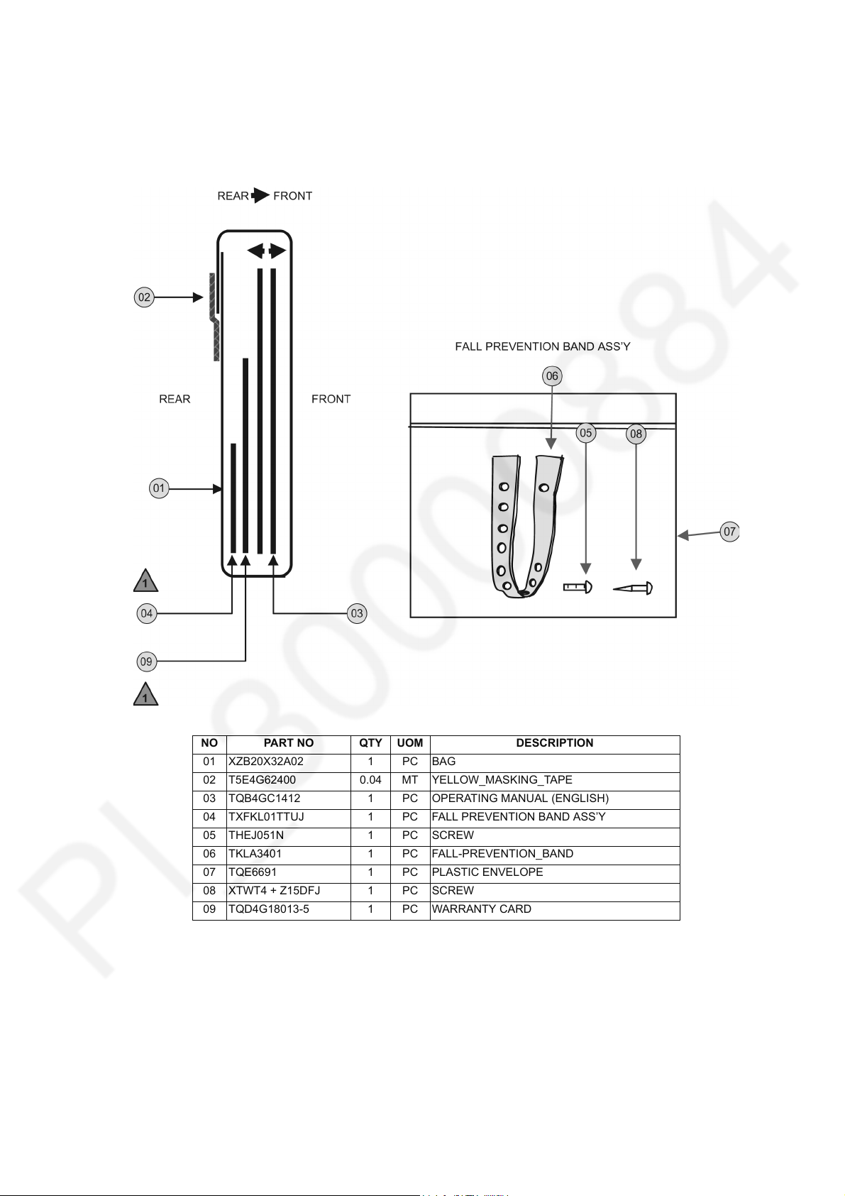
7.7. Fan Bag Assembly
1. Insert screw into bag and ensure bag fully seal (lock).
Insert all part into cover for fan bag.
2. Direction and sequence (depend by model - Refer part list for detail)
3. Fold cover for fan bag and stick with film tape.
TH-42C410K
NO PART NO QTY UOM DESCRIPTION
01 XZB20X32A02 1 PC BAG
02 T5E4G62400 0.04 MT YELLOW_MASKING_TAPE
03 TQB4GC1412 1 PC OPERATING MANUAL (ENGLISH)
04 TXFKL01TTUJ 1 PC FALL PREVENTION BAND ASS’Y
05 THEJ051N 1 PC SCREW
06 TKLA3401 1 PC FALL-PREVENTION_BAND
07 TQE6691 1 PC PLASTIC ENVELOPE
08 XTWT4 + Z15DFJ 1 PC SCREW
09 TQD4G18013-5 1 PC WARRANTY CARD
19
Page 20
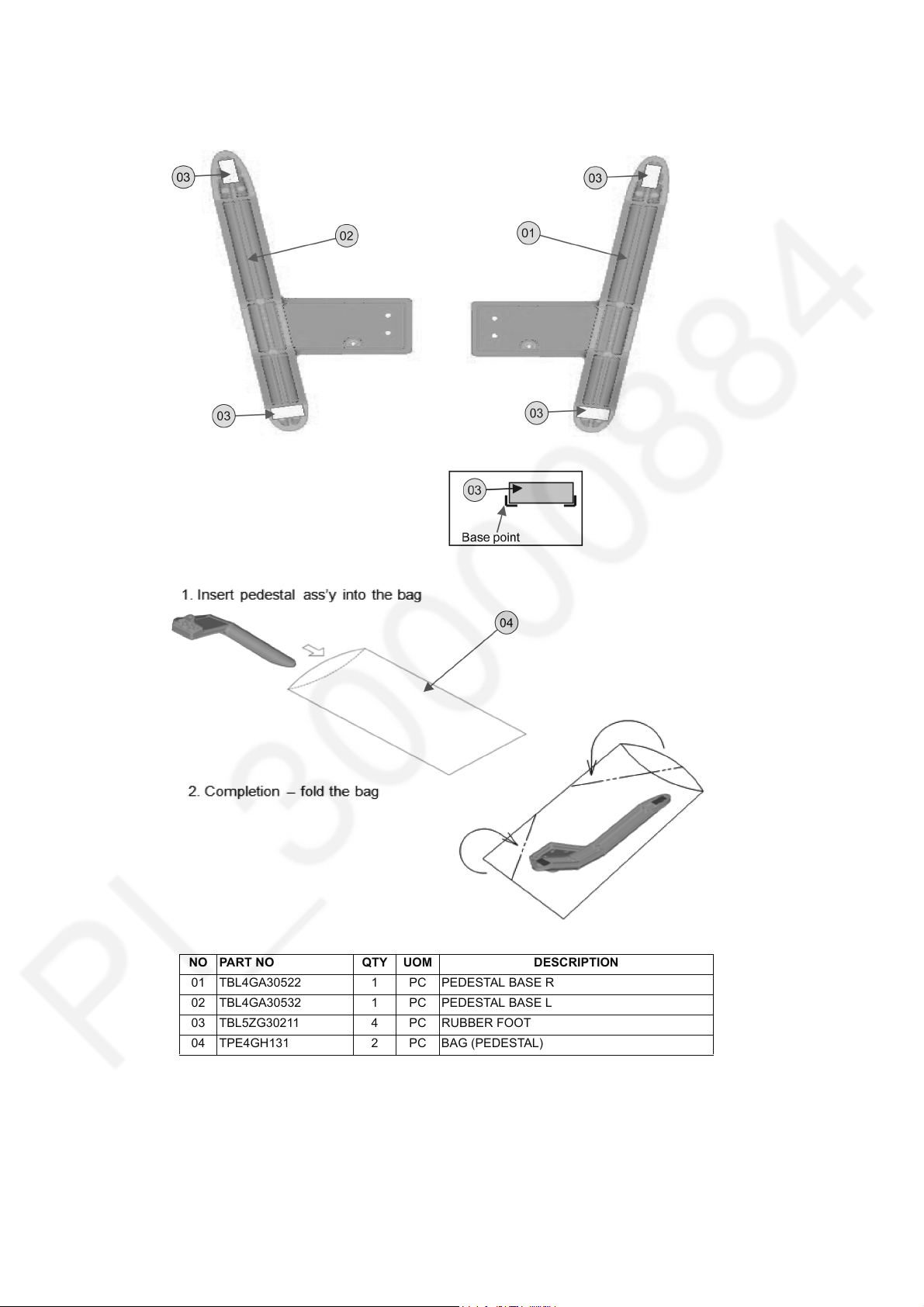
TH-42C410K
7.8. Pedestal Assembly
Fix pedestal follow below, need screw first before stick rubber foot.
NO PART NO QTY UOM DESCRIPTION
01 TBL4GA30522 1 PC PEDESTAL BASE R
02 TBL4GA30532 1 PC PEDESTAL BASE L
03 TBL5ZG30211 4 PC RUBBER FOOT
04 TPE4GH131 2 PC BAG (PEDESTAL)
20
Page 21
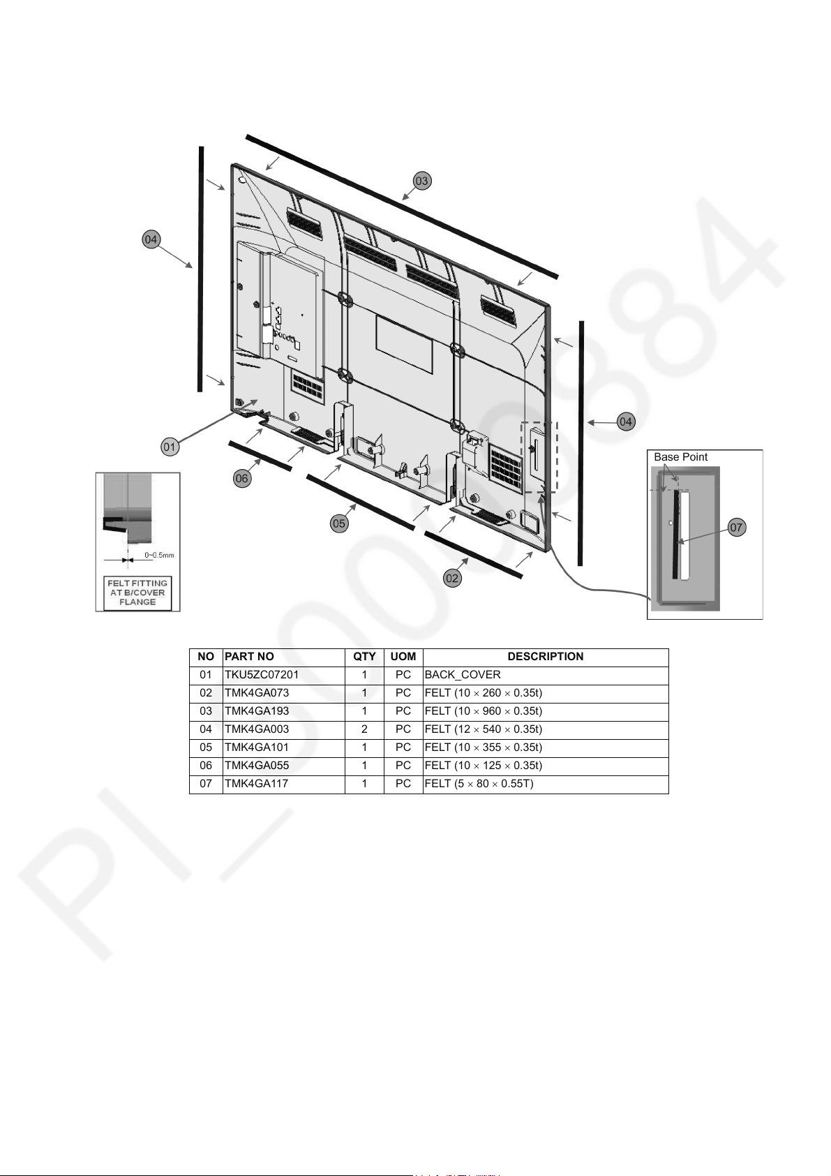
7.9. Back Cover
Stick felt at back cover.
TH-42C410K
NO PART NO QTY UOM DESCRIPTION
01 TKU5ZC07201 1 PC BACK_COVER
02 TMK4GA073 1 PC FELT (10 260 0.35t)
03 TMK4GA193 1 PC FELT (10 960 0.35t)
04 TMK4GA003 2 PC FELT (12 540 0.35t)
05 TMK4GA101 1 PC FELT (10 355 0.35t)
06 TMK4GA055 1 PC FELT (10 125 0.35t)
07 TM K4 GA 117 1 P C FE LT (5 80 0.55T)
21
Page 22
TH-42C410K
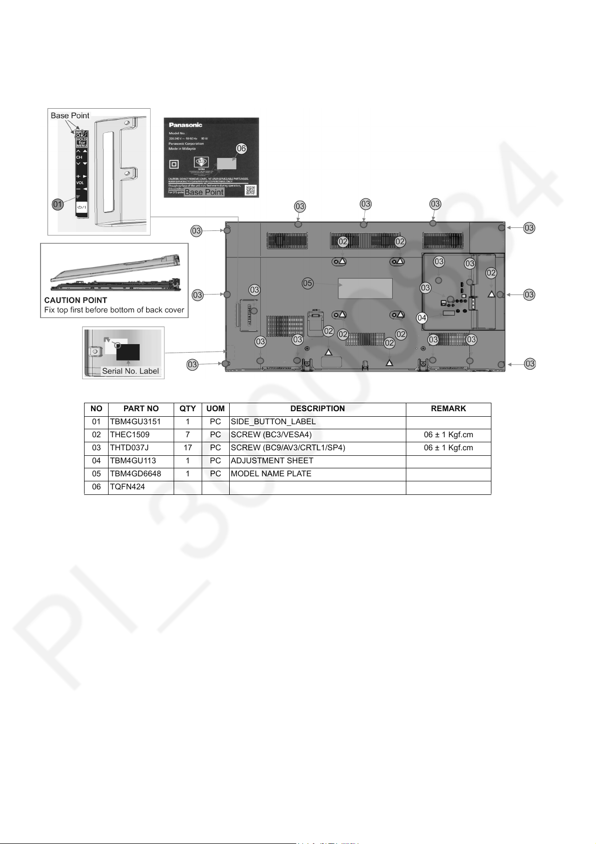
7.10. Back Cover - Label & Screw
1. Fix back cover and screw.
2. Stick side button label and serial number label.
NO PART NO QTY UOM DESCRIPTION REMARK
01 TBM4GU3151 1 PC SIDE_BUTTON_LABEL
02 THEC1509 7 PC SCREW (BC3/VESA4) 06 ± 1 Kgf.cm
03 THTD037J 17 PC SCREW (BC9/AV3/CRTL1/SP4) 06 ± 1 Kgf.cm
04 TBM4GU113 1 PC ADJUSTMENT SHEET
05 TBM4GD6648 1 PC MODEL NAME PLATE
06 TQFN424
22
Page 23

8 Measurements and Adjustments
8.1. Voltage chart of A-board
Set A-Board to a dummy set and check the satisfaction with the specified voltage as following table.
Power Supply Name Measurement Point Specification (V) Remark
SUB1.2V TP8004 1.14 - 1.26 -
SUB3.3V TP8003 3.19 - 3.46 -
SUB5V TP8002 4.92 - 5.25 -
STB5V TP8009 5.3 ± 0.3 -
PNL12V TP4300 11.5 - 12.5 -
8.2. Voltage chart of P-board
Set P-Board to a dummy load and check the satisfaction with the specified voltage as following table.
TH-42C410K
Output Test Point
24V TP7407 <1V 32 ± 1.6V
16V TP7410 <1V 15.7 ± 0.8V
5VS TP7501 5.2 ± 0.2V 5.2 ± 0.2V
PFC TP7201 or TP7202 <340V 390V ± 15V
Step 1 Supply AC 100V/230 to JK7101 connector in the P-Board. Main power button is OFF.
Step 2 TV_SUB_ON P2 connector - pin 8 (TP7416) DC2.5V ON.
Supply DC 2.5V to TV_SUB_ON P2 connector - pin 8 (TP7416), displayed as SWITCH.
NOTE : GND REFERENCE TP7413/TP7414/TP7415/TP7515/TP7516/TP7517 (COLD SIDE)
Step 1 Step 2
Specification
23
Page 24

TH-42C410K
Debug
UART
RST
STB5V
24M
1.8/3.3V
RST
PANEL
SP
SP
15V
I2S
HDMI 1
TUNER
HDMI 2 (w/ ARC)
MT5561
DDR2 1G
VIDEO/COMPONENT (automatic detection )
AUDIO
Silicon Lab
Low IF
SUB3.3V
SPI
64/128Mb
Sub3.3V
EEP_WP
EEPROM
64kbit
SLV[A4]
On-board
USB Slot
High-side
switch
USB (side) JK8601
Audio AMP
I2S AMP
RMT/KEY
LED
32” 10W x 2
39”㨪
10W x 2
*&(*&
LVDS
HD : (DATA 4pairs / CLK 1pair)
single8bit
FHD: (DATA 4pairs / CLK 1pair)
dual8bit
Op Amp
IIC
HK/S/A/US/MEX
On board (Si2157 )
YAMAHA
(same as MT5307project)
VIDEO
AUDIO
AV2(side)
JK3002(Prep)
Audio out JK3000(Prep.)
AV1 JK3100
(HDMI analog audio in)
HDMI1 JK4701
HDMI2 JK4702
CEC
3
2
10
W
39
”
Opt. D3051
Demod.
T2/ISDB/DTMB
TS
FOR US/MEX
Use MT5560
Chile/Peru
CAN Tuner
AV2 – HK/CHINA only
Audio Out –
HK/CHINA only
9 Block Diagram
9.1. Main Block Diagram
2
24
Page 25

10 Wiring Connection Diagram
10.1. Wire Dressing 1
TH-42C410K
25
Page 26

TH-42C410K
10.2. Wire Dressing 2
Stick pet tape for wire dressing.
NO PART NO QTY UOM DESCRIPTION REMARK
01 T4FP10050 0.59 MT PET_TAPE (0.06*6) 60 mm 6 pcs
26
Page 27

11 Schematic Diagram
Model No. : TH-42C410K A-Board (1/14)
TH-42C410K
27
Page 28

Model No. : TH-42C410K A-Board (2/14)
Page 29

Model No. : TH-42C410K A-Board (3/14)
Page 30

Model No. : TH-42C410K A-Board (4/14)
Page 31

Model No. : TH-42C410K A-Board (5/14)
Page 32

Model No. : TH-42C410K A-Board (6/14)
Page 33

Model No. : TH-42C410K A-Board (7/14)
Page 34

Model No. : TH-42C410K A-Board (8/14)
Page 35

Model No. : TH-42C410K A-Board (9/14)
Page 36

Model No. : TH-42C410K A-Board (10/14)
Page 37

Model No. : TH-42C410K A-Board (11/14)
Page 38

Model No. : TH-42C410K A-Board (12/14)
Page 39

Model No. : TH-42C410K A-Board (13/14)
Page 40

Model No. : TH-42C410K A-Board (14/14)
Page 41

Model No. : TH-42C410K GK-Board
Page 42

Model No. : TH-42C410K K-Board
Page 43

Model No. : TH-42C410K LD-Board
Page 44

Model No. : TH-42C410K P-Board (1/2)
Page 45

Model No. : TH-42C410K P-Board (2/2)
Page 46

TH-42C410K
12 Printed Circuit Board
Model No. : TH-42C410K A-Board (Top Component Side)
46
Page 47

Model No. : TH-42C410K A-Board (Bottom Component Side)
Page 48

Model No. : TH-42C410K GK-Board
Page 49

Model No. : TH-42C410K K-Board
Page 50

Model No. : TH-42C410K LD-Board
Page 51

Model No. : TH-42C410K P-Board (Top Component Side)
Page 52

Model No. : TH-42C410K P-Board (Bottom Component Side)
Page 53

13 Exploded View and Replacement Parts List
Model No. : TH-42C410K Parts Location
TH-42C410K
53
Page 54

Model No. : TH-42C410K Packing Exploded View 1
Page 55

Model No. : TH-42C410K Packing Exploded View 2
Page 56

Model No. : TH-42C410K Parts List
Change Safety
CAPACITOR
Ref.
No.
C2008 F1G1E103A144 C 0.01UF 25V
C2014 F1H1E104A161 C 0.1UF, 25V
C2015 F1K1V106A010 C 10UF, 35V
C2016 F1G1C104A146 C 0.1UF, 16V
C2017 F1G1C103A173 C 0.01UF, 16V
C2023 F1G1H102A946 C 1000PF, 50V
C2024 F1G1H102A946 C 1000PF, 50V
C2025 F1G1H102A946 C 1000PF, 50V
C2026 F1G1H102A946 C 1000PF, 50V
C2027 F1G1H102A946 C 1000PF, 50V
C2028 F1G1H101A948 C 100PF, 50V
C2801 F1H1H103B047 C 0.01UF, 50V
C2802 F1H1H103B047 C 0.01UF, 50V
C2803 F1H1H103B047 C 0.01UF, 50V
C2804 F1H1C104A178 C 0.1UF, 16V
C2806 F1H1H103B047 C 0.01UF, 50V
C2807 F1J1A106A043 C 10UF, 10V
C2808 F1H1C104A178 C 0.1UF, 16V
C2851 F1J1H104A902 C 0.1UF, 50V
C2852 F1J1H104A902 C 0.1UF, 50V
C3093 F1G1A473A079 C 0.047UF, 10V
C3095 F1G1A473A079 C 0.047UF, 10V
C3097 F1G1A473A079 C 0.047UF, 10V
C3108 F1G1H100A948 C 10PF, 50V
C3109 F1G1H100A948 C 10PF, 50V
C3110 F1G1H100A948 C 10PF, 50V
C3169 F1J1A106A043 C 10UF, 10V
C3170 F1J1A106A043 C 10UF, 10V
C3173 F1G1H152A946 C 1500PF, 50V
C3174 F1G1A473A079 C 0.047UF, 10V
C4010 F1H1H103B047 C 0.01UF, 50V
C4011 F1H1H103B047 C 0.01UF, 50V
C4012 F1J1C475A225 C 4.7UF, 16V
C4300 F1K1V106A010 C 10UF, 35V
C4302 F1G1C104A146 C 0.1UF, 16V
C4303 F1G1C223A173 C 0.022F, 16V
C4305 F1G1E332A172 C 3300PF, 25V
C4306 F1K1V106A010 C 10UF, 35V
C4307 F1K1V106A010 C 10UF, 35V
C4308 F1K1V106A010 C 10UF, 35V
C4502 F1G1C104A146 C 0.1UF, 16V
C4503 F1G1H101A948 C 100PF, 50V
C4900 F1K1V106A010 C 10UF, 35V
C4901 F1K1V106A010 C 10UF, 35V
C4902 F1J1E105A287 C 1UF, 25V
C4903 F1K1V106A010 C 10UF, 35V
C4904 F1J1E105A287 C 1UF, 25V
C4905 F1H1C105A167 C 1UF, 16V
C4906 F1K1V106A010 C 10UF, 35V
C4907 F1J1E105A287 C 1UF, 25V
C4908 F1K1V106A010 C 10UF, 35V
C4909 F1J1E105A287 C 1UF, 25V
C4919 F1J1E224A272 C 0.22UF, 25V
C4920 F1J1E224A272 C 0.22UF, 25V
C4921 F1H1E104A161 C 0.1UF, 25V
C4922 F1H1E104A161 C 0.1UF, 25V
C4923 F1H1E104A161 C 0.1UF, 25V
C4924 F1H1E104A161 C 0.1UF, 25V
C5028 F1G1C104A146 C 0.1UF, 16V
C5170 F1G1A224A069 C 0.22UF, 10V
C5614 F1J1A106A043 C 10UF, 10V
Part No. Part Name & Description Q'ty Remarks
Page 57

Model No. : TH-42C410K Parts List
Change Safety
Ref.
No.
C5615 F1J1A106A043 C 10UF, 10V
C5616 F1G1C104A146 C 0.1UF, 16V
C5624 F1J1A106A043 C 10UF, 10V
C5625 F1G1C104A146 C 0.1UF, 16V
C5703 F1G1A105A047 C 1UF, 10V
C5704 F1G1A105A047 C 1UF, 10V
C5717 F1J1A106A043 C 10UF, 10V
C5718 F1J1A106A043 C 10UF, 10V
C6704 F1J1A106A043 C 10UF, 10V
C6705 F1G1C473A146 C 0.047F, 16V
C6707 F1G1C104A146 C 0.1UF, 16V
C6708 F1J1A106A043 C 10UF, 10V
C6710 F1G1C104A146 C 0.1UF, 16V
C6712 F1G1A105A047 C 1UF, 10V
C6713 F1G1A105A047 C 1UF, 10V
C6720 F1G1H220A948 C 22PF, 50V
C6721 F1G1H220A948 C 22PF, 50V
C6722 F1G1C104A146 C 0.1UF, 16V
C6723 F1G1H220A948 C 22PF, 50V
C6724 F1G1H220A948 C 22PF, 50V
C6726 F1G1H220A948 C 22PF, 50V
C6727 F1G1H220A948 C 22PF, 50V
C6728 F1G1H102A948 C 1000PF, 50V
C6732 F1G1C473A146 C 0.047F, 16V
C6736 F1G1H101A948 C 100PF, 50V
C6737 F1G1H101A948 C 100PF, 50V
C6753 F1G1H5R0A947 C 5PF, 50V
C6754 F1G1H5R0A947 C 5PF, 50V
C6768 F1G1H102A946 C 1000PF, 50V
C6769 F1G1E103A144 C 0.01UF 25V
C6770 F1G1E103A144 C 0.01UF 25V
C6771 F1G1E103A144 C 0.01UF 25V
C6772 F1G1E103A144 C 0.01UF 25V
C6773 F1G1H102A946 C 1000PF, 50V
C6774 F1G1C104A146 C 0.1UF, 16V
C6775 F1G1C104A146 C 0.1UF, 16V
C6777 F1G0J105A049 C 1UF, 10V
C6781 F1G1H331A946 C 330PF, 50V
C6782 F1G1H121A834 C 120PF, 50V
C6783 F1G1H121A834 C 120PF, 50V
C6788 F1G1H101A948 C 100PF, 50V
C6789 F1G1H181A834 C 180PF, 50V
C6790 F1G1H181A834 C 180PF, 50V
C6791 F1G1H102A948 C 1000PF, 50V
C6793 F1G1H102A948 C 1000PF, 50V
C6794 F1G1C104A146 C 0.1UF, 16V
C6795 F1G1C104A146 C 0.1UF, 16V
C6797 F1G1H102A946 C 1000PF, 50V
C6798 F1G1H102A946 C 1000PF, 50V
C6799 F1H1H181B052 C 180PF, 50V
C6804 F1G1C104A146 C 0.1UF, 16V
C6805 F1J1A106A043 C 10UF, 10V
C6806 F1J1A106A043 C 10UF, 10V
C6809 F1G1C104A146 C 0.1UF, 16V
C6820 F1G1C104A146 C 0.1UF, 16V
C6822 F1G1C104A146 C 0.1UF, 16V
C6830 F1G1C104A146 C 0.1UF, 16V
C6832 F1J1A106A043 C 10UF, 10V
C6838 F1G1C104A146 C 0.1UF, 16V
C6840 F1G1C104A146 C 0.1UF, 16V
C6844 F1G1C104A146 C 0.1UF, 16V
C6847 F1G1H8R0A833 C 8PF, 50V
Part No. Part Name & Description Q'ty Remarks
Page 58

Model No. : TH-42C410K Parts List
Change Safety
Ref.
No.
C6848 F1G1H8R0A833 C 8PF, 50V
C6864 F1G1C104A146 C 0.1UF, 16V
C6872 F1G1C104A146 C 0.1UF, 16V
C6873 F1G1C104A146 C 0.1UF, 16V
C7102 F1AAF471A019 C 470PF, 1KV
C7103 F1AAF471A019 C 470PF, 1KV
C7104 F0CAF2240010 C 0.22UF, 240V
C7105 F0CAF2240010 C 0.22UF, 240V
C7201 F1H1H102B052 C 1000PF, 50V
C7202 F1J1H222A911 C 2200PF, 50V
C7203 F1H1H104B047 C 0.1UF, 50V
C7204 F1J1H104A902 C 0.1UF, 50V
C7205 F1J1H102A909 C 1000PF, 50V
C7206 F1J1E475A257 C 4.7UF, 25V
C7207 F1A3A221A060 C 220PF, 1KV
C7209 ECWFD2W824KC C 0.82UF , 240V
C7213 F2A2W6500001 C 65UF, 450V
C7214 F1J1H103A900 C 0.01UF, 50V
C7220 F1J1H103A900 C 0.01UF, 50V
C7221 F1A3A221A060 C 220PF, 1KV
C7302 F1J1H473A900 C 0.047UF, 50V
C7303 F1J1H104A902 C 0.1UF, 50V
C7304 F1A3A221A060 C 220PF, 1KV
C7305 F1J1H104A902 C 0.1UF, 50V
C7306 F1J1H104A902 C 0.1UF, 50V
C7307 F1J1H101A906 C 100PF, 50V
C7310 F2A1E4710124 C 470UF, 25V
C7311 F1J1H105A919 C 1UF, 50V
C7312 F1H1C474A178 C 0.47UF, 16V
C7313 F1J1H102A909 C 1000PF, 50V
C7316 F1A3A471A060 C 470PF, 1KV
C7317 ECWH8223HAC C 0.022UF, Z, 800V
C7318 F1AAF471A019 C 470PF, 1KV
C7320 F1A3A102A060 C 1000PF, 1KV
C7417 F1J1C474A238 C 0.47UF, 16V
C7418 F1H1H104B047 C 0.1UF, 50V
C7421 F1H1H104B047 C 0.1UF, 50V
C7422 F2AZZ4710003 C 470UF, 250V
C7423 F2AZZ2220001 C 2200UF , 240V
C7432 F1J1C475A225 C 4.7UF, 16V
C7433 F1K1V106A010 C 10UF, 35V
C7434 F1J1C475A225 C 4.7UF, 16V
C7524 F1J1H104A902 C 0.1UF, 50V
C7525 F1J1H221A906 C 220PF, 50V
C7526 F1J1C475A225 C 4.7UF, 16V
C7527 F1K1E106A167 C 10UF, 25V
C7529 F1J1H104A902 C 0.1UF, 50V
C7530 F1J1H104A902 C 0.1UF, 50V
C7541 F1K1E106A167 C 10UF, 25V
C7543 F1J1H103A900 C 0.01UF, 50V
C7544 F1J1H103A900 C 0.01UF, 50V
C7800 F1J1H101A906 C 100PF, 50V
C7801 F1J1H103A900 C 0.01UF, 50V
C7802 F1J1H103A900 C 0.01UF, 50V
C7803 F1J1E224A272 C 0.22UF, 25V
C7804 F1J1H103A900 C 0.01UF, 50V
C7805 F1J1H103A900 C 0.01UF, 50V
C7806 F1J1E105A287 C 1UF, 25V
C7807 F1J1E224A272 C 0.22UF, 25V
C7809 F1J1E105A287 C 1UF, 25V
C7810 F1J1E224A272 C 0.22UF, 25V
C7812 F1A3A221A060 C 220PF, 1KV
Part No. Part Name & Description Q'ty Remarks
Page 59

Model No. : TH-42C410K Parts List
Change Safety
Ref.
No.
C7813 F2A2C470A222 C 47UF, 160V
C7814 F2AZZ4710003 C 470UF, 250V
C7816 F1A3A221A060 C 220PF, 1KV
C7817 F2A2C470A222 C 47UF, 160V
C7821 F1J2E1020002 C 1000PF, 250V
C7824 F1J1E224A272 C 0.22UF, 25V
C7827 F1J1H221A906 C 220PF, 50V
C7828 F1J1H221A906 C 220PF, 50V
C7829 F1J2E1020002 C 1000PF, 250V
C7832 F1J1H104A902 C 0.1UF, 50V
C7833 F1J1H104A902 C 0.1UF, 50V
C7838 F1J1E105A287 C 1UF, 25V
C8095 F1K1V106A010 C 10UF, 35V
C8097 F1G1C104A146 C 0.1UF, 16V
C8098 F1G1C103A173 C 0.01UF, 16V
C8100 F1G1E332A172 C 3300PF, 25V
C8101 F1J1A106A043 C 10UF, 10V
C8102 F1J1A106A043 C 10UF, 10V
C8103 F1H0J4750004 C 4.7UF, 6.3V
C8104 F1J1A106A043 C 10UF, 10V
C8105 F1K1V106A010 C 10UF, 35V
C8106 F1J1A106A043 C 10UF, 10V
C8108 F1G1C104A146 C 0.1UF, 16V
C8109 F1G1C103A173 C 0.01UF, 16V
C8111 F1G1E332A172 C 3300PF, 25V
C8112 F1J0J2260004 C 22UF, 6.3V
C8113 F1G1C103A173 C 0.01UF, 16V
C8115 F1H1C105A167 C 1UF, 16V
C8116 F1J0J2260004 C 22UF, 6.3V
C8117 F1G1C104A146 C 0.1UF, 16V
C8118 F1J0J2260004 C 22UF, 6.3V
C8121 F1K1V106A010 C 10UF, 35V
C8123 F1G1C104A146 C 0.1UF, 16V
C8124 F1G1C103A173 C 0.01UF, 16V
C8126 F1G1E332A172 C 3300PF, 25V
C8127 F1H1C105A167 C 1UF, 16V
C8128 F1G1C104A146 C 0.1UF, 16V
C8129 F1J0G2260001 C 22UF, 4V
C8130 F1J0G2260001 C 22UF, 4V
C8134 F1G1E472A172 C 4700PF, 25V
C8135 F1K1V106A010 C 10UF, 35V
C8137 F1G1C104A146 C 0.1UF, 16V
C8138 F1G1C103A173 C 0.01UF, 16V
C8140 F1G1H270A834 C 27PF, 50V
C8141 F1J0G2260001 C 22UF, 4V
C8142 F1G1H270A834 C 27PF, 50V
C8143 F1J0G2260001 C 22UF, 4V
C8146 F1G1A105A047 C 1UF, 10V
C8147 F1G1A105A047 C 1UF, 10V
C8148 F1H1C105A167 C 1UF, 16V
C8151 F1H1H103B047 C 0.01UF, 50V
C8152 F1G1A105A047 C 1UF, 10V
C8153 F1G1A105A047 C 1UF, 10V
C8162 F1G1C104A146 C 0.1UF, 16V
C8163 F1G1C103A173 C 0.01UF, 16V
C8164 F1J1A106A043 C 10UF, 10V
C8165 F1G1C104A146 C 0.1UF, 16V
C8166 F1G1C104A146 C 0.1UF, 16V
C8167 F1G1C104A146 C 0.1UF, 16V
C8168 F1H1C105A167 C 1UF, 16V
C8169 F1G1C104A146 C 0.1UF, 16V
C8170 F1G1C104A146 C 0.1UF, 16V
Part No. Part Name & Description Q'ty Remarks
Page 60

Model No. : TH-42C410K Parts List
Change Safety
DIODE
Ref.
No.
C8171 F1G1C104A146 C 0.1UF, 16V
C8172 F1G1A105A047 C 1UF, 10V
C8173 F1G1C104A146 C 0.1UF, 16V
C8174 F1H0J4750004 C 4.7UF, 6.3V
C8176 F1G1A105A047 C 1UF, 10V
C8177 F1G1C104A146 C 0.1UF, 16V
C8178 F1G1C104A146 C 0.1UF, 16V
C8179 F1G1C104A146 C 0.1UF, 16V
C8180 F1J1A106A043 C 10UF, 10V
C8184 F1J0G2260001 C 22UF, 4V
C8186 F1G1C104A146 C 0.1UF, 16V
C8187 F1G1C104A146 C 0.1UF, 16V
C8188 F1G1C104A146 C 0.1UF, 16V
C8189 F1G1A105A047 C 1UF, 10V
C8191 F1G1C104A146 C 0.1UF, 16V
C8192 F1G1C104A146 C 0.1UF, 16V
C8193 F1G1A105A047 C 1UF, 10V
C8196 F1H1C105A167 C 1UF, 16V
C8850 F1H0J4750004 C 4.7UF, 6.3V
C8900 F1G1C104A146 C 0.1UF, 16V
C8901 F1G1C104A146 C 0.1UF, 16V
D1001 DZ2J140M0L DIODE
D1002 DZ2J140M0L DIODE
D1003 DZ2J140M0L DIODE
D1004 DZ2J140M0L DIODE
D1005 DZ2J140M0L DIODE
D1007 DZ2J140M0L DIODE
D2006 D4ED11200003 DIODE
D2008 D4ED11200003 DIODE
D2800 DZ2J056M0L DIODE
D2802 B3AGB0000083 LED
D2851 DZ2J068M0L DIODE
D2852 DZ2J068M0L DIODE
D3101 K7AAAY000016 DIODE
D3103 D4EDY5R5A038 DIODE
D3104 D4EDY5R5A038 DIODE
D5007 DA2J10100L DIODE
D5009 DZ2J068M0L DIODE
D5013 B0JCED000012 DIODE
D5170 DZ2J200M0L DIODE
D5171 DA2J10100L DIODE
D5172 DZ2J068M0L DIODE
D5173 B0ADCK000001 DIODE
D5174 DZ2J068M0L DIODE
D5175 B0ADCK000001 DIODE
D6750 J0ZZB0000175 DIODE
D6752 B0ZBZ0000226 DIODE
D7101 ERZE08C621CD SURGE ABSORBER
D7104 B0EAKR000022 DIODE
D7105 B0EAKR000022 DIODE
D7106 B0EBNT000028 DIODE
D7211 B0JCMG000043 DIODE
D7215 B0HAPR000013 DIODE
D7221 B0ACCD000008 DIODE
D7301 DZ2J039M0L DIODE
D7302 B0HAGQ000001 DIODE
D7303 DZ2J039M0L DIODE
D7304 B0HAGQ000001 DIODE
D7305 B0ADCK000001 DIODE
D7306 B0BC027A0336 DIODE
D7307 B0BC027A0336 DIODE
Part No. Part Name & Description Q'ty Remarks
Page 61

Model No. : TH-42C410K Parts List
Change Safety
INTEGRATED CIRCUIT
COIL
Ref.
No.
D7308 B0BC027A0336 DIODE
D7309 B0JCMG000043 DIODE
D7310 B0JCMG000043 DIODE
D7311 B0BC027A0336 DIODE
D7401 B0JBSL000046 DIODE
D7402 B0JBSL000046 DIODE
D7404 DA2J10100L DIODE
D7405 DA2J10100L DIODE
D7408 B0JDSG000009 DIODE
D7409 B0JDSG000009 DIODE
D7411 DA2J10100L DIODE
D7503 B0JCPE000051 DIODE
D7800 B0FCAM000004 DIODE
D7801 B0ECKM000053 DIODE
D7802 B0BC015A0336 DIODE
D7803 B0ECKM000053 DIODE
D7804 DZ2J360M0L DIODE
D7805 B0ACCD000008 DIODE
D7806 B0BC015A0336 DIODE
D7807 B0FCAM000004 DIODE
D7808 DA2J10100L DIODE
D7809 DA2J10100L DIODE
D7810 B0ACCD000008 DIODE
D7811 DZ2J360M0L DIODE
D7812 DA2J10100L DIODE
D8001 B0JCED000012 DIODE
D8002 B0JCED000012 DIODE
IC4300 C0DBAYY02430 IC
IC4900 C1AB00003984 IC
IC5602 C0DBZYY00723 IC
IC5701 C0DBEYY00226 IC
IC5704 C0DBEYY00102 IC
IC6750 C1AB00004172 IC
IC6800 C1AB00004028 IC
IC7201 C0DBBYY00058 IC
IC7301 C0DBAYY01329 IC
IC7401 C0DBZYY00545 IC
IC7503 C0DBAYY01915 IC
IC7800 C0ZBZ0002179 IC
IC8001 C1AB00004200 IC
IC8002 C0DBAYY02437 IC
IC8003 C0DBAYY02430 IC
IC8004 C0DBAYY02430 IC
IC8005 C0DBAYY02430 IC
IC8008 C0DBGYY00887 IC
IC8900A TVR4G310-AA ROM VERSION ASSEMBLY
IC8902 C3EBJY000066 IC
L2000 J0JYC0000328 J0JYC0000065
L4300 G1C220MA0445 INDUCTOR
L4901 G1C220MA0533 INDUCTOR
L4902 G1C220MA0533 INDUCTOR
L4903 G1C220MA0533 INDUCTOR
L4904 G1C220MA0533 INDUCTOR
L5601 J0JYC0000464 BEAD CORE
L6704 J0JYC0000464 CHIP BEADS
L6706 J0JYC0000464 CHIP BEADS
L6761 J0JYC0000464 BEAD CORE
L6762 J0JYC0000464 BEAD CORE
L6763 G1CR27JA0097 COIL
L6765 G1C82NJ00010 COIL
Part No. Part Name & Description Q'ty Remarks
Page 62

Model No. : TH-42C410K Parts List
Change Safety
TRANSISTOR
Ref.
No.
L6772 G1CR27JA0097 COIL
L6773 G1CR27JA0097 COIL
L6774 G1CR27JA0097 COIL
L6775 G1CR22JA0097 CHIP BEADS
L6776 G1CR27JA0097 COIL
L6777 G1CR22JA0097 CHIP BEADS
L6778 G1CR22JA0097 CHIP BEADS
L6779 G1CR22JA0097 CHIP BEADS
L6800 J0JYC0000464 BEAD CORE
L6801 J0JYC0000464 BEAD CORE
L6802 J0JYC0000464 BEAD CORE
L7201 J0JYB0000044 BEAD CORE
L7207 J0JYC0000344 COIL
L7303 J0JYB0000044 BEAD CORE
L7502 G0C270MA0049 INDUCTOR
L7801 J0JHC0000075 BEAD CORE
L7805 J0JYA0000035 BEAD CORE
L7808 J0JHC0000075 BEAD CORE
L7812 J0JYA0000035 BEAD CORE
L7813 G0C660Z00002 COIL
L7814 G0C660Z00002 COIL
L8008 J0JYC0000464 BEAD CORE
L8048 G1C4R7ZA0311 INDUCTOR
L8049 G1C3R3MA0464 INDUCTOR
L8050 G1C150MA0533 INDUCTOR
L8051 G1C100MA0533 COIL
Q2004 B1ABCF000231 TRANSISTOR
Q2005 B1ABCF000231 TRANSISTOR
Q2007 B1ABCF000231 TRANSISTOR
Q4500 B1ABCF000231 TRANSISTOR
Q4501 B1ABCF000231 TRANSISTOR
Q4504 B1ABCF000231 TRANSISTOR
Q4505 B1ABCF000231 TRANSISTOR
Q5005 B1ADCE000022 TRANSISTOR
Q5006 B1ABCF000231 TRANSISTOR
Q5007 B1ABCF000231 TRANSISTOR
Q5009 B1ADCE000022 TRANSISTOR
Q5010 B1ADCE000022 TRANSISTOR
Q5011 B1ABCF000231 TRANSISTOR
Q5170 B1ABCF000231 TRANSISTOR
Q5171 B1ABCF000231 TRANSISTOR
Q5172 B1ABCF000231 TRANSISTOR
Q7201 B1CERR000096 TRANSISTOR
Q7202 B1ADCE000022 TRANSISTOR
Q7301 B1CFRR000028 TRANSISTOR
Q7302 B1CFRR000028 TRANSISTOR
Q7303 B1ADCE000022 TRANSISTOR
Q7401 B1ABCF000231 TRANSISTOR
Q7402 B1CFRG000069 TRANSISTOR
Q7403 B1CHRE000015 TRANSISTOR
Q7405 B1CFRG000069 TRANSISTOR
Q7800 B1CBHG000002 TRANSISTOR
Q7801 B1CERM000055 TRANSISTOR
Q7802 B1CFML000007 TRANSISTOR
Q7803 B1CFML000007 TRANSISTOR
Q7804 B1CERM000055 TRANSISTOR
Q7805 B1CBHG000002 TRANSISTOR
Q7810 B1ABCN000007 TRANSISTOR
Q7811 B1ABCN000007 TRANSISTOR
Q8002 B1CHPD000013 TRANSISTOR
Q8003 B1ABCF000231 TRANSISTOR
Part No. Part Name & Description Q'ty Remarks
Page 63

Model No. : TH-42C410K Parts List
Change Safety
RESISTORS
Ref.
No.
R0902 D0GA272JA023 M 2.7K Ohm, J, 1/16W
R0903 D0GA272JA023 M 2.7K Ohm, J, 1/16W
R0910 D0GAR00J0005 M 0 Ohm, 1/16W
R0911 D0GAR00J0005 M 0 Ohm, 1/16W
R0912 D0GAR00J0005 M 0 Ohm, 1/16W
R0913 D0GAR00J0005 M 0 Ohm, 1/16W
R0916 D0GAR00J0005 M 0 Ohm, 1/16W
R0917 D0GAR00J0005 M 0 Ohm, 1/16W
R0924 D0GA272JA023 M 2.7K Ohm, J, 1/16W
R0925 D0GA272JA023 M 2.7K Ohm, J, 1/16W
R0926 D0GA473JA039 M 47K Ohm, J, 1/16W
R0927 D0GA680JA023 M 68 Ohm, J, 1/16W
R0928 D0GA680JA023 M 68 Ohm, J, 1/16W
R0929 D0GA102JA023 M 1K Ohm, J, 1/16W
R0930 D0GA102JA023 M 1K Ohm, J, 1/16W
R0933 D1H82724A042 M 2.7K Ohm, J, 1/16 W
R0938 D0GA680JA023 M 68 Ohm, J, 1/16W
R0939 D0GA680JA023 M 68 Ohm, J, 1/16W
R0944 D1H86804A042 M 68 Ohm, J, 1/16 W
R0945 D1H86804A042 M 68 Ohm, J, 1/16 W
R1000 D0GA101JA023 M 100 Ohm, J, 1/16W
R2011 D0GA102JA023 M 1K Ohm, J, 1/16W
R2012 D0GA473JA039 M 47K Ohm, J, 1/16W
R2018 D0GA680JA023 M 68 Ohm, J, 1/16W
R2027 D0GA103JA023 M 10K Ohm, J, 1/16W
R2028 D0GA102JA023 M 1K Ohm, J, 1/16W
R2029 D0GAR00J0005 M 0 Ohm, 1/16W
R2030 D0GA222JA023 M 2.2K Ohm, J, 1/16W
R2031 D0GA473JA039 M 47K Ohm, J, 1/16W
R2032 D0GA473JA039 M 47K Ohm, J, 1/16W
R2033 D1BA1002A023 M 10K Ohm, F, 1/16W
R2034 D0GA102JA023 M 1K Ohm, J, 1/16W
R2035 D1BA4702A023 M 47K Ohm, F, 1/16W
R2045 D0GA183JA023 M 18K Ohm, J, 1/16W
R2046 D0GB101JA065 M 100 Ohm, J, 1/10W
R2047 D0GB153JA065 M 15K Ohm, J, 1/10W
R2049 D0GA103JA023 M 10K Ohm, J, 1/16W
R2050 D0GA473JA039 M 47K Ohm, J, 1/16W
R2052 D0GA223JA023 M 22K Ohm, J, 1/16W
R2053 D0GA473JA039 M 47K Ohm, J, 1/16W
R2800 D0GBR00J0004 M 0 Ohm, J, 1/10W
R2808 D0GBR00J0004 M 0 Ohm, J, 1/10W
R2820 D0GB470JA065 M 47 Ohm, J, 1/10W
R2821 D0GBR00J0004 M 0 Ohm, J, 1/10W
R2822 D0GD822JA052 M 8.2K Ohm, J, 1/8W
R2823 D1BB4301A073 M 4.3K Ohm, J, 1/10W
R2824 D1BB1001A073 M 1K Ohm, J, 1/10W
R2852 D1BD1911A203 M 1.91K Ohm, J, 1/16W
R2853 D1BD3091A203 M 3.09K Ohm , F, 1/16W
R2854 D1BD6041A203 M 6.04K Ohm , F, 1/16W
R2855 D1BD1692A203 M 16.9K Ohm, J, 1/16W
R3099 D0GA223JA023 M 22K Ohm, J, 1/16W
R3119 D0GA272JA023 M 2.7K Ohm, J, 1/16W
R3122 D1BD75R0A066 M 75 Ohm, J, 1/8W
R3124 D1BD75R0A066 M 75 Ohm, J, 1/8W
R3192 D0GA101JA023 M 100 Ohm, J, 1/16W
R3193 D0GA101JA023 M 100 Ohm, J, 1/16W
R3194 D1BD75R0A066 M 75 Ohm, J, 1/8W
R3196 D0GA101JA023 M 100 Ohm, J, 1/16W
R3201 D0GA473JA023 M 47K Ohm, J, 1/16W
R3202 D0GA473JA023 M 47K Ohm, J, 1/16W
Part No. Part Name & Description Q'ty Remarks
Page 64

Model No. : TH-42C410K Parts List
Change Safety
Ref.
No.
R3205 D0GA101JA023 M 100 Ohm, J, 1/16W
R3243 D0GA220JA023 M 22 Ohm, J, 1/16W
R4048 D0GA912JA023 M 9.1K Ohm, J, 1/16W
R4050 D1H8R0040016 M 0 Ohm, Z, 1/16 W
R4051 D1H8R0040016 M 0 Ohm, Z, 1/16 W
R4052 D1H8R0040016 M 0 Ohm, Z, 1/16 W
R4053 D1H8R0040016 M 0 Ohm, Z, 1/16 W
R4054 D1H8R0040016 M 0 Ohm, Z, 1/16 W
R4059 D0GA101JA023 M 100 Ohm, J, 1/16W
R4097 D0GA680JA023 M 68 Ohm, J, 1/16W
R4098 D0GA680JA023 M 68 Ohm, J, 1/16W
R4150 D0GA332JA023 M 3.3K Ohm, J, 1/16W
R4155 D0GAR00J0005 M 0 Ohm, 1/16W
R4156 D0GAR00J0005 M 0 Ohm, 1/16W
R4159 D0GAR00J0005 M 0 Ohm, 1/16W
R4300 D1BA4702A023 M 47K Ohm, F, 1/16W
R4301 D1BA3601A023 M 3.6K Ohm, F, 1/16W
R4302 D1BA5102A023 M 51K Ohm, F, 1/16W
R4303 D0GA102JA023 M 1K Ohm, J, 1/16W
R4500 D0GA750JA023 M 75 Ohm, J, 1/16W
R4501 D0GA750JA023 M 75 Ohm, J, 1/16W
R4503 D1H84734A042 M 47K Ohm, J, 1/16 W
R4504 D1H86804A042 M 68 Ohm, J, 1/16 W
R4513 D0GA820JA023 M 82 Ohm, J, 1/16W
R4514 D0GA220JA023 M 22 Ohm, J, 1/16W
R4515 D0GA473JA039 M 47K Ohm, J, 1/16W
R4516 D0GA473JA039 M 47K Ohm, J, 1/16W
R4517 D0GA473JA039 M 47K Ohm, J, 1/16W
R4518 D0GA104JA023 M 100K Ohm, J, 1/16W
R4519 D0GA104JA023 M 100K Ohm, J, 1/16W
R4520 D0GA473JA039 M 47K Ohm, J, 1/16W
R4521 D0GA911JA023 M 910 Ohm, J, 1/16W
R4522 D0GA911JA023 M 910 Ohm, J, 1/16W
R4523 D0GA104JA023 M 100K Ohm, J, 1/16W
R4524 D0GA181JA023 M 180 Ohm, J, 1/16W
R4900 D0GFR00J0005 M 0 Ohm, J, 1/3W
R4901 D1H86804A042 M 68 Ohm, J, 1/16 W
R4903 D1H8R0040016 M 0 Ohm, Z, 1/16 W
R4905 D0GBR00J0004 M 0 Ohm, J, 1/10W
R4906 D0GBR00J0004 M 0 Ohm, J, 1/10W
R4907 D0GA102JA023 M 1K Ohm, J, 1/16W
R4908 D0GBR00J0004 M 0 Ohm, J, 1/10W
R4909 D0GBR00J0004 M 0 Ohm, J, 1/10W
R4915 D0GA563JA023 M 56K Ohm, J, 1/16W
R4917 D0GAR00J0005 M 0 Ohm, 1/16W
R4918 D0GAR00J0005 M 0 Ohm, 1/16W
R4919 D0GA153JA023 M 15K Ohm, J, 1/16W
R4956 D0GA102JA023 M 1K Ohm, J, 1/16W
R4963 D0GA473JA039 M 47K Ohm, J, 1/16W
R4964 D0GA303JA023 M 30K Ohm, J, 1/16W
R4983 D0GA103JA023 M 10K Ohm, J, 1/16W
R5050 D0GA473JA039 M 47K Ohm, J, 1/16W
R5051 D0GAR00J0005 M 0 Ohm, 1/16W
R5078 D1BA2202A023 M 22K Ohm, F, 1/16W
R5079 D1BA3742A023 M 37.4K Ohm, F, 1/16W
R5080 D0GA473JA039 M 47K Ohm, J, 1/16W
R5081 D0GA103JA023 M 10K Ohm, J, 1/16W
R5082 D0GA104JA023 M 100K Ohm, J, 1/16W
R5084 D0GA473JA039 M 47K Ohm, J, 1/16W
R5085 D0GA103JA023 M 10K Ohm, J, 1/16W
R5086 D0GAR00J0005 M 0 Ohm, 1/16W
R5087 D1BA2202A023 M 22K Ohm, F, 1/16W
Part No. Part Name & Description Q'ty Remarks
Page 65

Model No. : TH-42C410K Parts List
Change Safety
Ref.
No.
R5088 D1BA1602A023 M 16K Ohm, F, 1/16W
R5090 D0GA473JA039 M 47K Ohm, J, 1/16W
R5091 D0GA102JA023 M 1K Ohm, J, 1/16W
R5092 D0GA472JA023 M 4.7K Ohm, J, 1/16W
R5093 D0GA472JA023 M 4.7K Ohm, J, 1/16W
R5095 D0GA473JA039 M 47K Ohm, J, 1/16W
R5096 D0GA473JA039 M 47K Ohm, J, 1/16W
R5097 D0GA103JA023 M 10K Ohm, J, 1/16W
R5098 D0GA473JA039 M 47K Ohm, J, 1/16W
R5099 D0GA472JA023 M 4.7K Ohm, J, 1/16W
R5170 D0GA103JA023 M 10K Ohm, J, 1/16W
R5171 D0GA332JA023 M 3.3K Ohm, J, 1/16W
R5173 D0GA104JA023 M 100K Ohm, J, 1/16W
R5175 D0GA473JA039 M 47K Ohm, J, 1/16W
R5176 D0GA473JA039 M 47K Ohm, J, 1/16W
R5177 D0GA473JA039 M 47K Ohm, J, 1/16W
R5178 D0GA473JA039 M 47K Ohm, J, 1/16W
R5606 D0GA103JA023 M 10K Ohm, J, 1/16W
R5607 D0GA103JA023 M 10K Ohm, J, 1/16W
R5609 D1H8R0040016 M 0 Ohm, Z, 1/16 W
R5610 D1BA1652A023 M 16.5K Ohm, F, 1/16W
R5709 D1BA1201A023 M 1.2K Ohm, F, 1/16W
R5710 D1BA3001A023 M 3K Ohm, F, 1/16W
R5731 D1BA1200A023 M 120 Ohm, F, 1/16W
R5732 D1BA56R0A023 M 56 Ohm, F, 1/16W
R5736 D0GA103JA023 M 10K Ohm, J, 1/16W
R5740 D0GBR00J0004 M 0 Ohm, J, 1/10W
R5742 D0GBR00J0004 M 0 Ohm, J, 1/10W
R5744 D0GAR00J0005 M 0 Ohm, 1/16W
R6725 D0GAR00J0005 M 0 Ohm, 1/16W
R6726 D0GAR00J0005 M 0 Ohm, 1/16W
R6727 D0GAR00J0005 M 0 Ohm, 1/16W
R6730 D0GA103JA023 M 10K Ohm, J, 1/16W
R6743 D0GA102JA023 M 1K Ohm, J, 1/16W
R6744 D0GA102JA023 M 1K Ohm, J, 1/16W
R6750 D0GA101JA023 M 100 Ohm, J, 1/16W
R6753 D0GA101JA023 M 100 Ohm, J, 1/16W
R6754 D0GA102JA023 M 1K Ohm, J, 1/16W
R6755 D0GA101JA023 M 100 Ohm, J, 1/16W
R6756 D0GA101JA023 M 100 Ohm, J, 1/16W
R6757 D0GA101JA023 M 100 Ohm, J, 1/16W
R6758 D0GA101JA023 M 100 Ohm, J, 1/16W
R6759 D0GA102JA023 M 1K Ohm, J, 1/16W
R6760 D0GA332JA023 M 3.3K Ohm, J, 1/16W
R6761 D0GA332JA023 M 3.3K Ohm, J, 1/16W
R6768 D0GA681JA023 M 680 Ohm, J, 1/16W
R6770 D0GA103JA023 M 10K Ohm, J, 1/16W
R6804 D0GAR00J0005 M 0 Ohm, 1/16W
R6805 D0GAR00J0005 M 0 Ohm, 1/16W
R6810 D0GA332JA023 M 3.3K Ohm, J, 1/16W
R6812 D0GA680JA023 M 68 Ohm, J, 1/16W
R6813 D0GA680JA023 M 68 Ohm, J, 1/16W
R6818 D0GA680JA023 M 68 Ohm, J, 1/16W
R6819 D0GAR00J0005 M 0 Ohm, 1/16W
R6820 D0GAR00J0005 M 0 Ohm, 1/16W
R6821 D0GAR00J0005 M 0 Ohm, 1/16W
R6840 D0GA471JA023 M 470K Ohm, J, 1/16W
R6846 D0GA680JA023 M 68 Ohm, J, 1/16W
R6847 D0GA680JA023 M 68 Ohm, J, 1/16W
R6848 D0GA680JA023 M 68 Ohm, J, 1/16W
R6849 D0GA680JA023 M 68 Ohm, J, 1/16W
R6850 D0GA680JA023 M 68 Ohm, J, 1/16W
Part No. Part Name & Description Q'ty Remarks
Page 66

Model No. : TH-42C410K Parts List
Change Safety
Ref.
No.
R6861 D0GA680JA023 M 68 Ohm, J, 1/16W
R6862 D0GA680JA023 M 68 Ohm, J, 1/16W
R6863 D0GA680JA023 M 68 Ohm, J, 1/16W
R6871 D0GA332JA023 M 3.3K Ohm, J, 1/16W
R6872 D0GA332JA023 M 3.3K Ohm, J, 1/16W
R6880 D0GAR00J0005 M 0 Ohm, 1/16W
R6881 D0GAR00J0005 M 0 Ohm, 1/16W
R6882 D0GBR00J0004 M 0 Ohm, J, 1/10W
R6884 D0GA103JA023 M 10K Ohm, J, 1/16W
R6885 D0GAR00J0005 M 0 Ohm, 1/16W
R6886 D0GAR00J0005 M 0 Ohm, 1/16W
R7101 D0GF105JA048 M 1M Ohm, J, 1/4W
R7102 D0GF105JA048 M 1M Ohm, J, 1/4W
R7103 D0GF105JA048 M 1M Ohm, J, 1/4W
R7104 D0GD102JA052 M 1K Ohm, J, 1/8W
R7105 D0GD102JA052 M 1K Ohm, J, 1/8W
R7201 ERX1SJR22V M 0.22 Ohm, J, 1/10W
R7202 ERX1SJR22V M 0.22 Ohm, J, 1/10W
R7203 D0GD563JA052 M 56K Ohm, J, 1/8W
R7204 D0GF101JA047 M 100 Ohm, J, 1/4W
R7205 D0GD470JA052 M 47 Ohm, J, 1/8W
R7206 D0GD4R7JA059 M 4.7 Ohm, J, 1/4W
R7207 D0GB104JA065 M 100K Ohm, J, 1/10W
R7208 ERX1SJR22V M 0.22 Ohm, J, 1/10W
R7211 D0GD104JA052 M 100K Ohm, J, 1/8W
R7212 D0GB683JA065 M 68K Ohm, J, 1/10W
R7219 D0GB513JA065 M 51K Ohm, J, 1/10W
R7220 D0GB223JA065 M 22K Ohm, J, 1/10W
R7224 D1BD8203A066 M 820K Ohm , F, 1/16W
R7225 D1BF1504A073 M 1.5M Ohm, F, 1/16W
R7226 D1BF1504A073 M 1.5M Ohm, F, 1/16W
R7227 D1BF1504A073 M 1.5M Ohm, F, 1/16W
R7228 D1BF1504A073 M 1.5M Ohm, F, 1/16W
R7229 D1BD2003A066 M 200K Ohm , F, 1/16W
R7230 D1BD4422A066 M 44.2K Ohm , F, 1/16W
R7231 D1BD4303A066 M 430K Ohm , F, 1/16W
R7232 D1BD3603A066 M 360K Ohm , F, 1/16W
R7234 D1BD8203A066 M 820K Ohm , F, 1/16W
R7240 D0GF225JA048 M 2.2M Ohm, J, 1/4W
R7241 D0GF225JA048 M 2.2M Ohm, J, 1/4W
R7242 D0GF225JA048 M 2.2M Ohm, J, 1/4W
R7243 D0GF225JA048 M 2.2M Ohm, J, 1/4W
R7244 D0GD124JA052 M 120K Ohm, J, 1/8W
R7302 D0GD101JA059 M 100 Ohm, J, 1/8W
R7303 D0GD101JA059 M 100 Ohm, J, 1/8W
R7304 D0AF2R2JA112 C 2.2 Ohm, J, 1/2W
R7305 D0AF121JA112 M 120 Ohm, J, 2W
R7306 D0GD222JA052 M 2.2K Ohm, J, 1/8W
R7307 D0GD562JA052 M 5.6K Ohm, J, 1/8W
R7308 D0GD222JA052 M 2.2K Ohm, J, 1/8W
R7311 D0B1106JA033 M 10M Ohm, J, 1W
R7312 D0AF153JA112 M 15K Ohm, J, 1/16W
R7314 D0GD103JA052 M 10K Ohm, J, 1/8W
R7315 D0GB222JA065 M 2.2K Ohm, J, 1/10W
R7317 D0GD223JA052 M 22K Ohm, J, 1/8W
R7318 D0GB473JA065 M 47K Ohm, J, 1/10W
R7319 D0GD473JA052 M 47K Ohm, J, 1/8W
R7320 D0GD103JA052 M 10K Ohm, J, 1/8W
R7321 D0GD100JA059 M 10 Ohm, J, 1/4W
R7322 D0GD100JA059 M 10 Ohm, J, 1/4W
R7323 D0GD223JA052 M 22K Ohm, J, 1/8W
R7324 D0GD223JA052 M 22K Ohm, J, 1/8W
Part No. Part Name & Description Q'ty Remarks
Page 67

Model No. : TH-42C410K Parts List
Change Safety
Ref.
No.
R7325 ERX1SJ1R0V M 1.0 Ohm, J, 1/10W
R7383 D0GDR00J0004 M 0 Ohm, J, 1/8W
R7397 D0GDR00J0004 M 0 Ohm, J, 1/8W
R7401 D0GD472JA052 M 4.7K Ohm, J, 1/8W
R7402 D0GD103JA052 M 10K Ohm, J, 1/8W
R7403 D0GD102JA052 M 1K Ohm, J, 1/8W
R7404 D0GD104JA052 M 100K Ohm, J, 1/8W
R7405 D0GD222JA052 M 2.2K Ohm, J, 1/8W
R7406 D1BD3301A066 M 3.3K Ohm , F, 1/16W
R7407 D0GB103JA065 M 10K Ohm, J, 1/10W
R7408 D1BD1872A066 M 18.7KOHM ,F, 1/16W
R7409 D0GD473JA052 M 47K Ohm, J, 1/8W
R7410 D0GD153JA052 M 15K Ohm, J, 1/8W
R7411 D0GD473JA052 M 47K Ohm, J, 1/8W
R7412 D0GD153JA052 M 15K Ohm, J, 1/8W
R7413 D1BD7503A066 M 750K Ohm , F, 1/16W
R7415 D0GD472JA052 M 4.7K Ohm, J, 1/8W
R7416 D0GD103JA052 M 10K Ohm, J, 1/8W
R7417 D0GD103JA052 M 10K Ohm, J, 1/8W
R7420 D0GD224JA052 M 2.2K Ohm, J, 1/8W
R7421 D0GD104JA052 M 100K Ohm, J, 1/8W
R7422 D0GD224JA052 M 2.2K Ohm, J, 1/8W
R7423 D0GD334JA052 M 3.3K Ohm, J, 1/8W
R7427 D0GDR00J0004 M 0 Ohm, J, 1/8W
R7533 D1BD7872A066 M 78.7K Ohm , F, 1/16W
R7534 D1BD1432A066 M 14.3K Ohm, F, 1/16W
R7535 D0GD514JA052 M 510K Ohm, J, 1/8W
R7536 D0GD100JA052 M 10 Ohm, J, 1/8W
R7802 D0GDR00J0004 M 0 Ohm, J, 1/8W
R7803 D0GD222JA052 M 2.2K Ohm, J, 1/8W
R7804 D0GDR00J0004 M 0 Ohm, J, 1/8W
R7805 D1BD1803A076 M 180K Ohm , F, 1/16W
R7806 D1BD2202A066 M 2.2K Ohm , F, 1/16W
R7807 D0GD153ZA034 M 15K Ohm, J, 1/8W
R7808 D0GD104JA052 M 100K Ohm, J, 1/8W
R7809 D1BD6802A203 M 68K Ohm , F, 1/16W
R7810 D1BD2202A203 M 2.2K Ohm , F, 1/16W
R7811 D0GDR00J0004 M 0 Ohm, J, 1/8W
R7812 D0GD104JA052 M 100K Ohm, J, 1/8W
R7813 D0GD393JA052 M 39K Ohm, J, 1/8W
R7816 D1BD1503A066 M 150K Ohm, F, 1/16W
R7817 D0GD104JA052 M 100K Ohm, J, 1/8W
R7818 D0GD152ZA034 M 1.5K Ohm, J, 1/16W
R7820 D0GD470JA059 M 47 Ohm, J, 1/4W
R7821 D0GD101JA052 M 100 Ohm, J, 1/8W
R7823 D0GD152JA052 M 1.5K Ohm, J, 1/8W
R7824 D1BD12R0A204 M 12 Ohm, J, 1/8W
R7825 D1BD12R0A204 M 12 Ohm, J, 1/8W
R7826 D1BD12R0A204 M 12 Ohm, J, 1/8W
R7827 D0GD104JA052 M 100K Ohm, J, 1/8W
R7828 D0GD104JA052 M 100K Ohm, J, 1/8W
R7829 D1BD12R0A204 M 12 Ohm, J, 1/8W
R7830 D0GD472JA052 M 4.7K Ohm, J, 1/8W
R7831 D1BD12R0A204 M 12 Ohm, J, 1/8W
R7832 D0GD470JA059 M 47 Ohm, J, 1/4W
R7834 D0GD101JA052 M 100 Ohm, J, 1/8W
R7836 D0GD100JA059 M 10 Ohm, J, 1/4W
R7837 D0GD473JA052 M 47K Ohm, J, 1/8W
R7839 ERX1SJR22V M 0.22 Ohm, J, 1/10W
R7840 D0GD474JA052 M 470K Ohm, J, 1/8W
R7841 ERX1SJR22V M 0.22 Ohm, J, 1/10W
R7842 ERX1SJR22V M 0.22 Ohm, J, 1/10W
Part No. Part Name & Description Q'ty Remarks
Page 68

Model No. : TH-42C410K Parts List
Change Safety
Ref.
No.
R7843 D0GD100JA059 M 10 Ohm, J, 1/4W
R7844 D0GD473JA052 M 47K Ohm, J, 1/8W
R7845 D0C1R33JA104 M 0.33 Ohm , J, 1W
R7846 ERX1SJR22V M 0.22 Ohm, J, 1/10W
R7847 D0GDR00J0004 M 0 Ohm, J, 1/8W
R7848 ERX1SJR22V M 0.22 Ohm, J, 1/10W
R7851 D1BD12R0A204 M 12 Ohm, J, 1/8W
R7852 D1BD12R0A204 M 12 Ohm, J, 1/8W
R7853 D1BD12R0A204 M 12 Ohm, J, 1/8W
R7854 D1BD12R0A204 M 12 Ohm, J, 1/8W
R7855 D1BD12R0A204 M 12 Ohm, J, 1/8W
R7857 D0GD104JA052 M 100K Ohm, J, 1/8W
R7862 D1BD4701A203 M 4.7K Ohm , F, 1/16W
R7863 D0GD152ZA034 M 1.5K Ohm, J, 1/16W
R7866 D1BD2003A203 M 200K Ohm , F, 1/16W
R7867 D1BD1803A076 M 180K Ohm , F, 1/16W
R7868 D0GD222JA052 M 2.2K Ohm, J, 1/8W
R7869 D0GD222JA052 M 2.2K Ohm, J, 1/8W
R7870 D0GD152JA052 M 1.5K Ohm, J, 1/8W
R7871 D0GD474JA052 M 470K Ohm, J, 1/8W
R7872 D1BD2003A203 M 200K Ohm , F, 1/16W
R7873 D0GF242JA048 M 2.4K Ohm, J, 1/4W
R7874 D0GF473JA048 M 47K Ohm, J, 1/4W
R7875 D0GF242JA048 M 2.4K Ohm, J, 1/4W
R7876 D0GF473JA048 M 47K Ohm, J, 1/4W
R7877 D0GF242JA048 M 2.4K Ohm, J, 1/4W
R7878 D0GF242JA048 M 2.4K Ohm, J, 1/4W
R7879 D0GF242JA048 M 2.4K Ohm, J, 1/4W
R7880 D0GF242JA048 M 2.4K Ohm, J, 1/4W
R7881 D0GF242JA048 M 2.4K Ohm, J, 1/4W
R7882 D0GF473JA048 M 47K Ohm, J, 1/4W
R7883 D0GF242JA048 M 2.4K Ohm, J, 1/4W
R7884 D0GF473JA048 M 47K Ohm, J, 1/4W
R7885 D0GF242JA048 M 2.4K Ohm, J, 1/4W
R7886 D0GF242JA048 M 2.4K Ohm, J, 1/4W
R7887 D0GF242JA048 M 2.4K Ohm, J, 1/4W
R7888 D0GF242JA048 M 2.4K Ohm, J, 1/4W
R7889 D0GD1R0JA052 M 1 Ohm, J, 1W
R7895 D1BD18R0A204 M 18 Ohm, F, 1/16W
R7897 D1BD18R0A204 M 18 Ohm, F, 1/16W
R7899 D0GD101JA052 M 100 Ohm, J, 1/8W
R8099 D1BA2002A023 M 20K Ohm, F, 1/16W
R8100 D1BA5601A023 M 5.6K Ohm, F, 1/16W
R8101 D0GA510JA023 M 51 Ohm, J, 1/16W
R8102 D0GA510JA023 M 51 Ohm, J, 1/16W
R8103 D1BA3002A023 M 30K Ohm, F, 1/16W
R8104 D1BA2400A023 M 240 Ohm, F, 1/16W
R8105 D1BA1302A023 M 13K Ohm, F, 1/16W
R8106 D1BA1502A023 M 15K Ohm, F, 1/16W
R8107 D1BA4702A023 M 47K Ohm, F, 1/16W
R8113 D1BA4701A023 M 4.7K Ohm, F, 1/16W
R8114 D1BA2002A023 M 20K Ohm, F, 1/16W
R8115 D1BA1802A023 M 18K Ohm, F, 1/16W
R8116 D1BA3001A023 M 3K Ohm, F, 1/16W
R8118 D0GA101JA023 M 100 Ohm, J, 1/16W
R8120 D0GAR00J0005 M 0 Ohm, 1/16W
R8123 D1BA2202A023 M 22K Ohm, F, 1/16W
R8124 D1BA1202A023 M 12K Ohm, F, 1/16W
R8126 D0GA473JA039 M 47K Ohm, J, 1/16W
R8128 D0GBR00J0004 M 0 Ohm, J, 1/10W
R8130 D0GA472JA023 M 4.7K Ohm, J, 1/16W
R8137 D0GA472JA023 M 4.7K Ohm, J, 1/16W
Part No. Part Name & Description Q'ty Remarks
Page 69

Model No. : TH-42C410K Parts List
Change Safety
TRANSFORMER
OTHERS
Ref.
No.
R8138 D0GA473JA039 M 47K Ohm, J, 1/16W
R8141 D0GA473JA039 M 47K Ohm, J, 1/16W
R8145 D0GBR00J0004 M 0 Ohm, J, 1/10W
R8146 D0GA472JA023 M 4.7K Ohm, J, 1/16W
R8147 D0GA750JA023 M 75 Ohm, J, 1/16W
R8148 D0GA103JA023 M 10K Ohm, J, 1/16W
R8149 D1BA1001A023 M 1K Ohm, F, 1/16W
R8150 D1BA1001A023 M 1K Ohm, F, 1/16W
R8151 D0GA103JA023 M 10K Ohm, J, 1/16W
R8900 D0GA101JA023 M 100 Ohm, J, 1/16W
R8901 D0GA472JA023 M 4.7K Ohm, J, 1/16W
R8902 D0GA103JA023 M 10K Ohm, J, 1/16W
R8903 D0GBR00J0004 M 0 Ohm, J, 1/10W
R8904 D0GA680JA023 M 68 Ohm, J, 1/16W
R8905 D0GA680JA023 M 68 Ohm, J, 1/16W
R8906 D0GA680JA023 M 68 Ohm, J, 1/16W
R8907 D0GA680JA023 M 68 Ohm, J, 1/16W
R8908 D0GA103JA023 M 10K Ohm, J, 1/16W
R8909 D0GA472JA023 M 4.7K Ohm, J, 1/16W
R8910 D0GA102JA023 M 1K Ohm, J, 1/16W
T7202 G4DYA0000496 TRANSFORMER
T7301 G4DYA0000565 TRANSFORMER
A02 K1KY14BA0484 CONNECTOR
A10 K1KY07BA0483 CONNECTOR
A11 K1MY51BA0526 CONNECTOR
A12 K1KY04BA0387 CONNECTOR
CF7101 D4CAY4R7A096 THERMISTORS RESISTOR
CN0100 K1KA14A00248 CONNECTOR
F7101 K5E502YYA213 FUSE
GK4 K1KY03BA0402 CONNECTOR
JA1 D0GDR00J0004 M 0 Ohm, J, 1/8W
JA10 D0GFR00J0005 M 0 Ohm, J, 1/3W
JA11 D0GFR00J0005 M 0 Ohm, J, 1/3W
JA13 D0GFR00J0005 M 0 Ohm, J, 1/3W
JA14 D0GFR00J0005 M 0 Ohm, J, 1/3W
JA16 D0GFR00J0005 M 0 Ohm, J, 1/3W
JA17 D0GFR00J0005 M 0 Ohm, J, 1/3W
JA2 D0GDR00J0004 M 0 Ohm, J, 1/8W
JA3 D0GDR00J0004 M 0 Ohm, J, 1/8W
JA4 D0GDR00J0004 M 0 Ohm, J, 1/8W
JA5 D0GDR00J0004 M 0 Ohm, J, 1/8W
JK3101 K1U511D00002 AV TERMINAL
JK4700 K1FY119D0029 TERMINAL
JK4701 K1FY119D0029 TERMINAL
JK6752 K1ZZ00001557 TUNER SHIELD
JK7101 K2AAYB000010 TERMINAL
JK8450 K1FY104B0092 TERMINAL
JS0048 D0GAR00J0005 M 0 Ohm, 1/16W
JS0067 D0GAR00J0005 M 0 Ohm, 1/16W
JS7406 D0GFR00J0005 M 0 Ohm, J, 1/3W
JS7501 D0GDR00J0004 M 0 Ohm, J, 1/8W
K10 K1KY07BA0483 CONNECTOR
LD1 K1KY09BA0402 CONNECTOR
LD2 K1KY07BA0385 CONNECTOR
LF7103 G0B183GA0082 LINE FILTER
LF7104 G0B183GA0082 LINE FILTER
LF7105 G0B350GA0083 LINE FILTER
P2 K1KY14BA0491 CONNECTOR
P4 K1KY09BA0402 CONNECTOR
P5 K1KY03BA0402 CONNECTOR
Part No. Part Name & Description Q'ty Remarks
Page 70

Model No. : TH-42C410K Parts List
Change Safety
Ref.
No.
PC7301 B3PAA0000674 PHOTO COUPLER
PC7302 B3PAA0000674 PHOTO COUPLER
PC7303 B3PAA0000674 PHOTO COUPLER
RM2800 B3RBB0000018 PHOTO DETECTOR
SN2800 B3JB00000219 PHOTO DETECTOR
SW2851 EVQ11G05R SWITCH
SW2852 EVQ11G05R SWITCH
SW2853 EVQ11G05R SWITCH
SW2854 EVQ11G05R SWITCH
SW2855 EVQ11G05R SWITCH
SW2857 EVQ11G05R SWITCH
X6750 H0J240500067 CRYSTAL OSCILLATOR
X6800 H0J410500003 CRYSTAL OSCILLATOR
X8301 H0J240500095 CRYSTAL OSCILLATOR
ZA7101 K4AD01A00004 RUG TERMINAL
ZA7102 K4AD01A00004 RUG TERMINAL
ZA7105 K4AD01A00004 RUG TERMINAL
ZA7801 K4AD01A00004 RUG TERMINAL
Part No. Part Name & Description Q'ty Remarks
Page 71

Model No. : TH-42C410K Parts List
Change Safety
Exploded View
Electrical Replacement Part List
Ref.
No.
1 K2CQ2YY00122 AC CORD
2 L0EYAA000052 SPEAKER UNIT
3 N2QAYB000976 REMOTE TRANSMITTER
4 TBL5ZX08911 STAND METAL ASSEMBLY
5 TKK5ZC50501A LED PANEL
6 TKP5ZA32202 SIDE AV BRACKET
7 TPD4GA07081 CUSHION CORNER
8 TPD4GA07091 CUSHION ACCESSORY L
9 TPD4GA07101 CUSHION BOTTOM CENTRE
10 TPD4GA07111 CUSHION TOP CENTRE
11 TPE4GH073 SET COVER
12 TQZ4GB961 FAN BAG ASSEMBLY
13 TXFPC01WAUK CARTON ASSEMBLY
14 TZBL4GX00281 PEDESTAL ASSEMBLY
15 TZTU4GA1563 BACK COVER COMPLETE
Part No. Part Name & Description Q'ty Remarks
TBM4GD6648 MODEL NAME PLATE
TBX5ZA03301 KEY BUTTON BRACKET
TSCKF0690001 LVDS CABLE
TZLP104VTUA 42 IN-HOUSE PANEL
TXN/K1UWUH K PRINT ASSEMBLY
TXNLD1AHVX LD PRINT ASSEMBLY
TZRNP11TJUK P PRINT ASSEMBLY
TZRNP12TNUK GK PRINT ASSEMBLY
TZT/A1WAUK A PRINT ASSEMBLY
 Loading...