

Panasonic TH-42BT300W, TH-50BT300W User Manual
Operating Instructions
High Defi nition Plasma Display
Model No.
TH-42BT300W
TH-50BT300W
English
Please read these instructions before operating your set
and retain them for future reference.
TQB4TC0134

Dear Panasonic Customer
Welcome to the Panasonic family of customers. We hope that you will have many years of
enjoyment from your new Plasma Display.
To obtain maximum benefit from your set, please read these Instructions before making
any adjustments, and retain them for future reference.
Retain your purchase receipt also, and note down the model number and serial number of
your set in the space provided on the rear cover of these instructions.
Visit our Panasonic Web Site http://panasonic.net
Table of Contents
Important Safety Notice ........................................... 3
Safety Precautions ................................................... 4
3D Safety Precautions ............................................. 7
Accessories .............................................................. 9
Accessories Supply ................................................. 9
Remote Control Batteries ........................................ 9
Connections ............................................................ 10
Speaker connection ............................................... 10
AC cord connection and fi xing, cable fi xing ........... 10
Video equipment connection ..................................11
VIDEO and COMPONENT / RGB IN connection ...11
HDMI connection ................................................... 12
DVI-D IN connection .............................................. 12
PC Input Terminals connection .............................. 13
SERIAL Terminals connection ............................... 14
Power On / Off ......................................................... 15
Selecting the input signal ...................................... 18
Basic Controls ........................................................ 19
ASPECT Controls ................................................... 21
Digital Zoom ............................................................ 22
Viewing 3D images ................................................. 23
To view the 3D images .......................................... 23
Troubleshooting for 3D Eyewear .......................... 24
Table of images that can be seen for each 3D
Picture Format and the source image format ........ 24
On-Screen Menu Displays ..................................... 25
Adjusting Pos. /Size ............................................... 26
Picture Adjustments ............................................... 29
Advanced settings ................................................. 31
Colour space adjustment (Colour gamut) .............. 33
Picture Profi les ....................................................... 35
Saving profi les ....................................................... 36
Loading profi les ..................................................... 37
Editing profi les ....................................................... 38
Sound Adjustment .................................................. 39
SDI Sound Output ................................................. 39
Setup menu ............................................................. 40
Component / RGB-in select ................................... 40
YUV / RGB-in select .............................................. 40
External scaler mode ............................................. 41
Power save ............................................................ 42
Standby save ......................................................... 42
PC Power management ........................................ 42
DVD-D Power management .................................. 42
No signal power off ................................................ 42
No activity power off .............................................. 42
OSD design ........................................................... 43
OSD position ......................................................... 43
OSD Language ...................................................... 43
3D Settings ............................................................ 44
Signal menu .......................................................... 45
Waveform Monitor ................................................. 47
Marker settings ...................................................... 48
RGB/MONO settings ............................................. 50
Screensaver .......................................................... 51
Extended life settings ............................................ 53
Customizing the Input labels ................................. 56
Function Button Settings ....................................... 56
Day/Time Setup / On/Off Timer Setup ................... 57
Network Setup ....................................................... 58
Options Adjustments ............................................. 59
3D Safety Precautions (To hide 3D Safety
Precautions) ......................................................... 61
Audio input select .................................................. 62
Using FUNCTION button ........................................ 63
Using Network Function ........................................ 65
Example of Network Connection ........................... 65
Command Control ................................................. 65
PJLink™ Protocol .................................................. 66
Using Web Browser Control .................................. 67
Before Using Web Browser Control....................... 67
Access from Web Browser .................................... 67
Display Control (BASIC CONTROL/OPTION
CONTROL Screen) ............................................... 68
NETWORK SETTING (Network Setup Screen) .... 69
Password Setting (Password Setup Screen) ........ 69
Troubleshooting ..................................................... 70
List of Aspect Modes ............................................. 71
Applicable Input Signals ........................................ 72
ID Remote Control Function .................................. 73
Shipping condition ................................................. 74
Specifi cations ......................................................... 75
2
Important Safety Notice
WARNING
1) To prevent damage which may result in fi re or shock hazard, do not expose this appliance to dripping
or splashing.
Do not place containers with water (fl ower vase, cups, cosmetics, etc.) above the set. (including on
shelves above, etc.)
No naked fl ame sources, such as lighted candles, should be placed on / above the set.
2) To prevent electric shock, do not remove cover. No user serviceable parts inside. Refer servicing to qualifi ed
service personnel.
3) Do not remove the earthing pin on the power plug. This apparatus is equipped with a three pin earthing-type
power plug. This plug will only fi t an earthing-type power outlet. This is a safety feature. If you are unable to
insert the plug into the outlet, contact an electrician.
Do not defeat the purpose of the earthing plug.
4) To prevent electric shock, ensure the earthing pin on the AC cord power plug is securely connected.
CAUTION
This appliance is intended for use in environments which are relatively free of electromagnetic fi elds.
Using this appliance near sources of strong electromagnetic fi elds or where electrical noise may overlap with the
input signals could cause the picture and sound to wobble or cause interference such as noise to appear.
To avoid the possibility of harm to this appliance, keep it away from sources of strong electromagnetic fi elds.
IMPORTANT INFORMATION
If a display is not positioned in a suffi ciently stable location, it can be potentially hazardous due to falling. Many
injuries, particularly to children, can be avoided by taking simple precautions such as:
• Using cabinets or stands recommended by the manufacturer of the display.
• Only using furniture that can safely support the display.
• Ensuring the display is not overhanging the edge of the supporting furniture.
• Not placing the display on tall furniture (for example, cupboards or bookcases) without anchoring both the furniture
and the display to a suitable support.
• Not standing the displays on cloth or other materials placed between the display and supporting furniture.
• Educating children about the dangers of climbing on furniture to reach the display or its controls.
Trademark Credits
• VGA is a trademark of International Business Machines Corporation.
• Macintosh is a registered trademark of Apple Inc., USA.
• SVGA, XGA, SXGA and UXGA are registered trademarks of the Video Electronics Standard Association.
Even if no special notation has been made of company or product trademarks, these trademarks have been fully respected.
• HDMI, the HDMI Logo, and High-Defi nition Multimedia Interface are trademarks or registered trademarks of HDMI
Licensing LLC in the United States and other countries.
Note:
Do not allow a still picture to be displayed for an extended period, as this can cause a permanent image retention
to remain on the Plasma Display.
Examples of still pictures include logos, video games, computer images, teletext and images displayed in 4:3 mode.
3

Safety Precautions
WARNING
Setup
This Plasma Display is for use only with the following optional accessories. Use with any other type of optional
accessories may cause instability which could result in the possibility of injury.
(All of the following accessories are manufactured by Panasonic Corporation.)
• Speakers ........................................................................ TY-SP42P8W-K (for TH-42BT300W),
TY-SP50P8W-K (for TH-50BT300W)
• Pedestal ......................................................................... TY-ST20-K
• Mobile stand ................................................................... TY-ST58PF20
• Wall-hanging bracket (vertical) ....................................... TY-WK42PV20
• Wall-hanging bracket (angled) ....................................... TY-WK42PR20
• Ceiling-hanging bracket ................................................. TY-CE42PS20
• BNC Dual Video Terminal Board .................................... TY-FB9BD
• HD-SDI Terminal Board .................................................. TY-FB9HD
• HD-SDI Terminal Board with audio ................................ TY-FB10HD
• Dual Link HD-SDI Terminal Board .................................. TY-FB11DHD
• Dual HD-SDI Terminal Board for 3D .............................. TY-FB30DHD3D
• Dual HDMI Terminal Board ............................................ TY-FB10HMD
• DVI-D Terminal Board .................................................... TY-FB11DD
• Dual DVI-D Terminal Board for 3D ................................. TY-FB30DD3D
• AV Terminal Box ............................................................. TY-TB10AV
• 3D IR TRANSMITTER ................................................... TY-3D30TRW
Always be sure to ask a qualifi ed technician to carry out set-up.
Small parts can present choking hazard if accidentally swallowed. Keep small parts away from young children. Discard
unneeded small parts and other objects, including packaging materials and plastic bags/sheets to prevent them from
being played with by young children, creating the potential risk of suffocation.
Do not place the Plasma Display on sloped or unstable surfaces, and ensure that the Plasma Display does
not hang over the edge of the base.
• The Plasma Display may fall off or tip over.
Do not place any objects on top of the Plasma Display.
• If water is spills onto the Plasma Display or foreign objects get inside it, a short-circuit may occur which could result
in fi re or electric shock. If any foreign objects get inside the Plasma Display, please consult your local Panasonic
dealer.
Transport only in upright position!
• Transporting the unit with its display panel facing upright or downward may cause damage to the internal
circuitry.
Ventilation should not be impeded by covering the ventilation openings with items such as newspapers, table
cloths and curtains.
For suffi cient ventilation;
If using the pedestal (optional accessory), leave a space of 10 cm or more at the top, left and right, and 7 cm
or more at the rear, and also keep the space between the bottom of the display and the fl oor surface.
If using some other setting-up method, follow the manual of it. (If there is no specifi c indication of installation
dimension in the installation manual, leave a space of 10 cm or more at the top, bottom, left and right, and 7 cm
or more at the rear.)
4

Safety Precautions
When using the Plasma Display
The Plasma Display is designed to operate on 220 - 240 V AC, 50/60 Hz.
Do not cover the ventilation holes.
• Doing so may cause the Plasma Display to overheat, which can cause fi re or damage to the Plasma Display.
Do not stick any foreign objects into the Plasma Display.
• Do not insert any metal or fl ammable objects into the ventilations holes or drop them onto the Plasma Display, as
doing so can cause fi re or electric shock.
Do not remove the cover or modify it in any way.
• High voltages which can cause severe electric shocks are present inside the Plasma Display. For any inspection,
adjustment and repair work, please contact your local Panasonic dealer.
Ensure that the mains plug is easily accessible.
An apparatus with CLASS I construction shall be connected to a mains socket outlet with a protective earthing connection.
Do not use any power supply cord other than that provided with this unit.
• Doing so may cause fi re or electric shocks.
Securely insert the power supply plug as far as it will go.
• If the plug is not fully inserted, heat may be generated which could cause fi re. If the plug is damaged or the wall
socket is loose, they shall not be used.
Do not handle the power supply plug with wet hands.
• Doing so may cause electric shocks.
Do not do anything that may damage the power cable. When disconnecting the power cable, pull on the plug body, not the cable.
• Do not damage the cable, make any modifi cations to it, place heavy objects on top of it, heat it, place it near any
hot objects, twist it, bend it excessively or pull it. To do so may cause fi re and electric shock. If the power cable is
damaged, have it repaired at your local Panasonic dealer.
If the Plasma Display is not going to be used for any prolonged length of time, unplug the power supply plug
from the wall outlet.
If problems occur during use
If a problem occurs (such as no picture or no sound), or if smoke or an abnormal odour starts to come out
from the Plasma Display, immediately unplug the power supply plug from the wall outlet.
• If you continue to use the Plasma Display in this condition, fi re or electric shock could result. After checking that
the smoke has stopped, contact your local Panasonic dealer so that the necessary repairs can be made. Repairing
the Plasma Display yourself is extremely dangerous, and shall never be done.
If water or foreign objects get inside the Plasma Display, if the Plasma Display is dropped, or if the cabinet
becomes damages, disconnect the power supply plug immediately.
•
A short circuit may occur, which could cause fi re. Contact your local Panasonic dealer for any repairs that need to be made.
5

Safety Precautions
CAUTION
When using the Plasma Display
Do not bring your hands, face or objects close to the ventilation holes of the Plasma Display.
• Heated air comes out from the ventilation holes at the top of Plasma Display will be hot. Do not bring your hands
or face, or objects which cannot withstand heat, close to this port, otherwise burns or deformation could result.
Be sure to disconnect all cables before moving the Plasma Display.
• If the Plasma Display is moved while some of the cables are still connected, the cables may become damaged,
and fi re or electric shock could result.
Disconnect the power supply plug from the wall socket as a safety precaution before carrying out any
cleaning.
• Electric shocks can result if this is not done.
Clean the power cable regularly to prevent it becoming dusty.
• If dust built up on the power cord plug, the resultant humidity can damage the insulation, which could result in fi re.
Pull the power cord plug out from the wall outlet and wipe the mains lead with a dry cloth.
Do not burn or breakup batteries.
• Batteries must not be exposed to excessive heat such as sunshine, fi re or the like.
This Plasma Display radiates infrared rays, therefore it may affect other infrared communication equipment.
Install your infrared sensor in a place away from direct or refl ected light from your Plasma Display.
Cleaning and maintenance
The front of the display panel has been specially treated. Wipe the panel surface gently using only a cleaning
cloth or a soft, lint-free cloth.
• If the surface is particularly dirty, wipe with a soft, lint-free cloth which has been soaked in pure water or water in
which neutral detergent has been diluted 100 times, and then wipe it evenly with a dry cloth of the same type until
the surface is dry.
• Do not scratch or hit the surface of the panel with fi ngernails or other hard objects, otherwise the surface may
become damaged. Furthermore, avoid contact with volatile substances such as insect sprays, solvents and thinner,
otherwise the quality of the surface may be adversely affected.
If the cabinet becomes dirty, wipe it with a soft, dry cloth.
• If the cabinet is particularly dirty, soak the cloth in water to which a small amount of neutral detergent has been
added and then wring the cloth dry. Use this cloth to wipe the cabinet, and then wipe it dry with a dry cloth.
• Do not allow any detergent to come into direct contact with the surface of the Plasma Display. If water droplets get
inside the unit, operating problems may result.
• Avoid contact with volatile substances such as insect sprays, solvents and thinner, otherwise the quality of the
cabinet surface may be adversely affected or the coating may peel off. Furthermore, do not leave it for long periods
in contact with articles made from rubber or PVC.
6
3D Safety Precautions
Safety Precautions
WARNING
Small Parts
3D Eyewear contains small parts (battery and specialised band, etc.) and must be kept out of reach of small
children to avoid accidental ingestion.
Disassembly
Do not disassemble or modify the 3D Eyewear.
Lithium Battery
Batteries must not be exposed to excessive heat such as sunshine, fi re or the like.
CAUTION
To enjoy 3D images safely and comfortably, please read these instructions fully.
Use for commercial applications and public viewing
Someone in authority should responsibly convey the precautions for use of the 3D Eyewear to the user.
3D Eyewear
Do not drop, exert pressure on, or step on the 3D Eyewear.
Always store the 3D Eyewear in the case provided when not in use.
Be careful of the tips of the frame when putting on the 3D Eyewear.
Be careful not to trap a fi nger in the hinge section of the 3D Eyewear.
Pay special attention when children are using the 3D Eyewear.
3D Eyewear should not be used by children younger than 5 - 6 years old, as a guideline.
All children must be fully supervised by parents or guardians who must ensure their safety and health
throughout the using 3D Eyewear.
7

Safety Precautions
Viewing 3D Content
Content for 3D viewing includes commercially available Blu-ray discs, 3D broadcasts, etc.
When preparing your own 3D content, ensure that it is properly produced.
Do not use the 3D Eyewear if you have a history of over-sensitivity to light, heart problems, or have any other
existing medical conditions.
Please stop using the 3D Eyewear immediately, if you feel tired, are not feeling well or experience any other
uncomfortable sensation.
Take an appropriate break after viewing a 3D movie.
Take a break of between 30 - 60 minutes after viewing 3D content on interactive devices such as 3D games
or computers.
Be careful not to strike the screen or other people unintentionally. When using the 3D Eyewear the distance
between the user and screen can be misjudged.
The 3D Eyewear must only be worn when viewing 3D content.
If you do not look toward the screen for a while when viewing 3D images, the 3D Eyewear may be turned off
automatically.
If you suffer from any eyesight problems (short / far-sighted, astigmatism, eyesight differences in left and
right), please ensure to correct your vision before using the 3D Eyewear.
Stop using the 3D Eyewear if you can clearly see double images when viewing 3D content.
Do not use the 3D Eyewear at a distance less than the recommended distance.
View from at least the recommended distance (3 times the effective height of the screen).
Recommended distance
TH-42BT300W: 1.6m
TH-50BT300W: 1.9m
When the top and bottom area of the screen is blackened, such as movies, view the screen at a distance
3 times further than the height of the actual image. (That makes the distance closer than above recommended
fi gure.)
3D Eyewear Use
Before using the 3D Eyewear, ensure no breakable objects surrounding the user to avoid any accidental
damage or injury.
Remove the 3D Eyewear before moving around to avoid falling or accidental injury.
Always put the 3D Eyewear in the case (supplied) after use.
Use the 3D Eyewear only for the intended purpose and nothing else.
Do not use 3D Eyewear in the condition of high temperature.
Do not use if the 3D Eyewear is physically damaged.
Do not use any devices that emit the infrared signals near the 3D Eyewear, as this may cause the 3D Eyewear
false operations.
Do not use devices (such as mobile phones or personal transceivers) that emit strong electromagnetic waves
near the 3D Eyewear as this may cause the 3D Eyewear to malfunction.
Stop using the 3D Eyewear immediately if a malfunction or fault occurs.
Stop using the 3D Eyewear immediately if you experience any redness, pain, or skin irritation around the nose
or temples.
In rare cases, the materials used in the 3D Eyewear may cause an allergic reaction.
Lithium Battery
Danger of explosion if battery is incorrectly replaced. Replace only with the same or equivalent type.
8
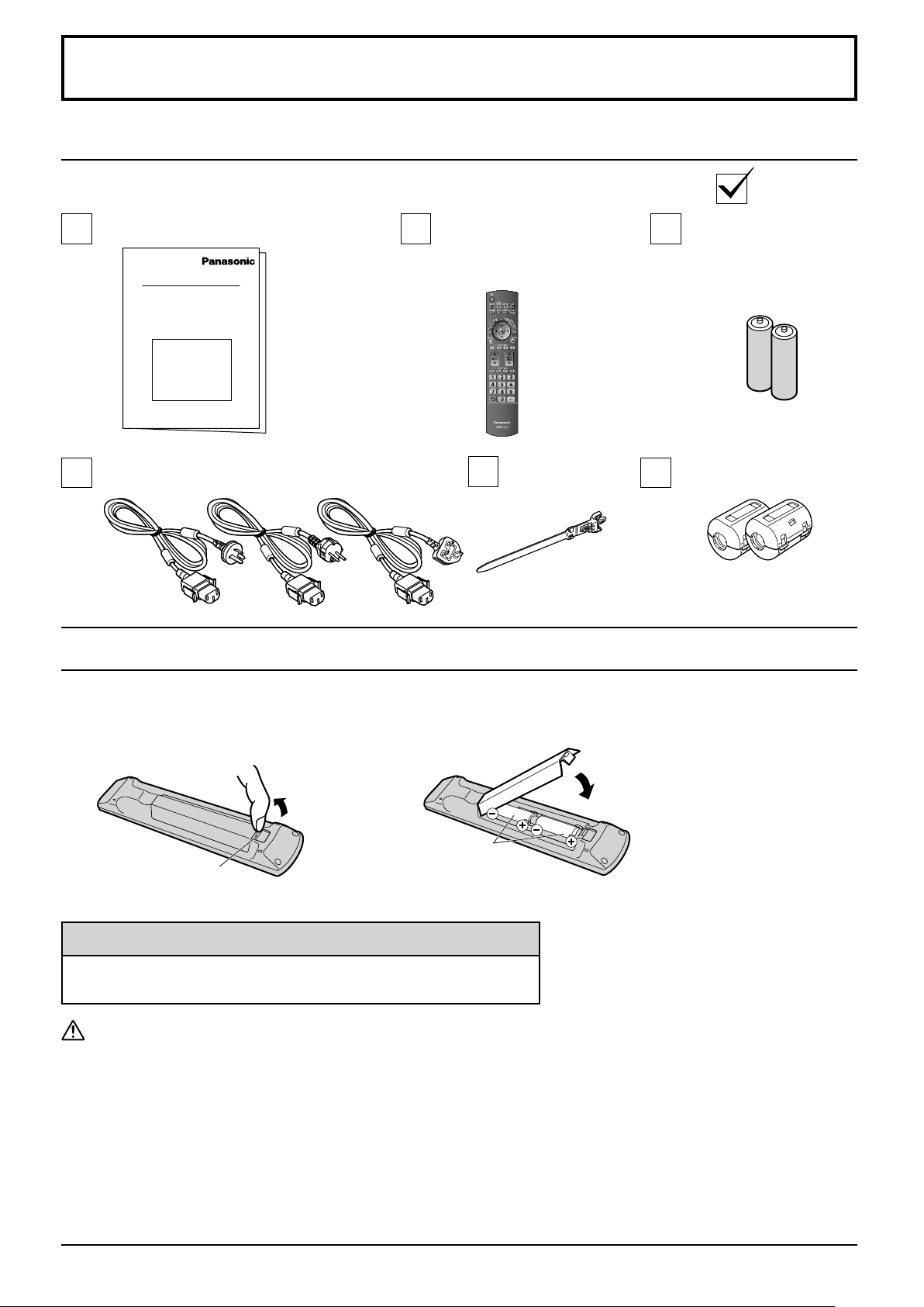
Accessories
Accessories Supply
Check that you have the accessories and items shown
Operating Instruction book
Power supply cord
Remote Control
Transmitter
N2QAYB000689
Remote Control Batteries
Clamper × 1
TMME289
Batteries for the Remote
Control Transmitter
(R6 Size × 2)
Ferrite core × 2
J0KG00000014
Use the Ferrite cores to comply
with the EMC standard.
(see page 65)
Requires two R6 batteries.
1. Pull and hold the hook, then open
the battery cover.
Open
Hook
2. Insert batteries - note correct
polarity ( + and -).
Close
“R6” size
Helpful Hint:
For frequent remote control users, replace old batteries with Alkaline
batteries for longer life.
Precaution on battery use
Incorrect installation can cause battery leakage and corrosion that will damage the remote control transmitter.
Disposal of batteries should be in an environment-friendly manner.
Observe the following precaution:
1. Batteries shall always be replaced as a pair. Always use new batteries when replacing the old set.
2. Do not combine a used battery with a new one.
3. Do not mix battery types (example: “Zinc Carbon” with “Alkaline”).
4. Do not attempt to charge, short-circuit, disassemble, heat or burn used batteries.
5.
Battery replacement is necessary when remote control acts sporadically or stops operating the Plasma Display set.
6. Do not burn or breakup batteries.
Batteries must not be exposed to excessive heat such as sunshine, fi re or the like.
9
Connections
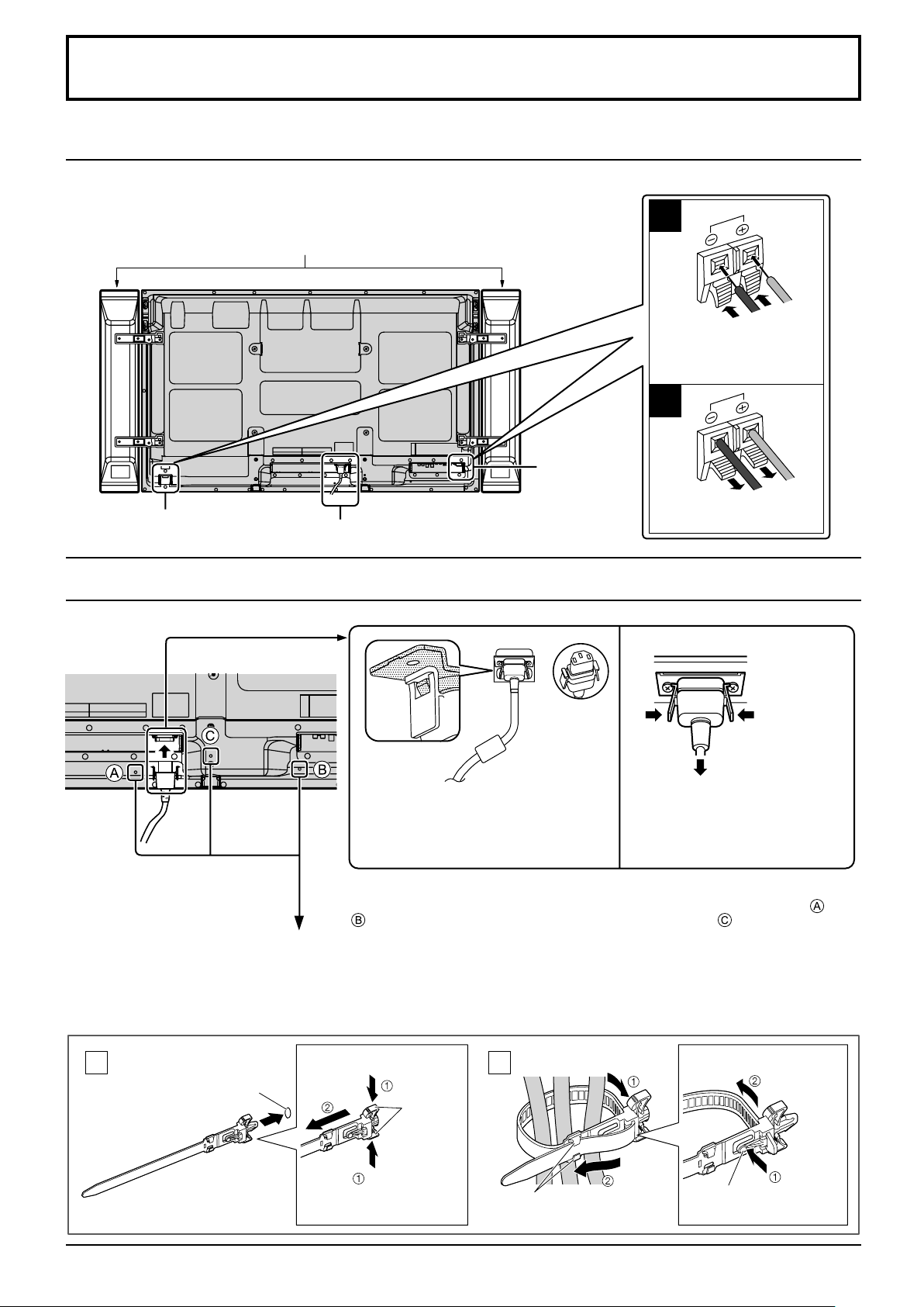
Speaker connection
When connecting the speakers, be sure to use only the optional accessory speakers.
Refer to the speaker’s Installation Manual for details on speaker installation.
Speakers (Optional accessories)
1
Red
Black
While pressing the lever,
insert the core wire.
2
Red
Speaker terminal (R)
AC cord connection (see page 15)
Speaker
terminal (L)
Black
Return the lever.
AC cord connection and fi xing, cable fi xing
AC cord fi xing
Unplug the AC cord
Plug the AC cord into the display unit.
Plug the AC cord until it clicks.
Note:
Make sure that the AC cord is locked on
both the left and right sides.
When using the Wall-hanging bracket (vertical)
Note:
When using the Wall-hanging bracket (vertical)(TY-WK42PV20), use the holes
and to secure the cables. If the clamper is used on the hole , the cables may
be caught by the wall-hanging bracket.
Using the clamper
Secure any excess cables with clamper as required.
Note:
One clamper is supplied with this unit. In case of securing cables at three positions, please purchase it separately.
Unplug the AC cord pressing the
two knobs.
Note:
When disconnecting the AC cord, be
absolutely sure to disconnect the AC
cord plug at the socket outlet fi rst.
10
Attach the clamper
1
Insert the clamper
in a hole.
hole
To remove from the unit:
snaps
Keep pushing
both side
snaps
Bundle the cables
2
hooks
Set the
tip in the
hooks
To loosen:
knob
Keep
pushing
the knob
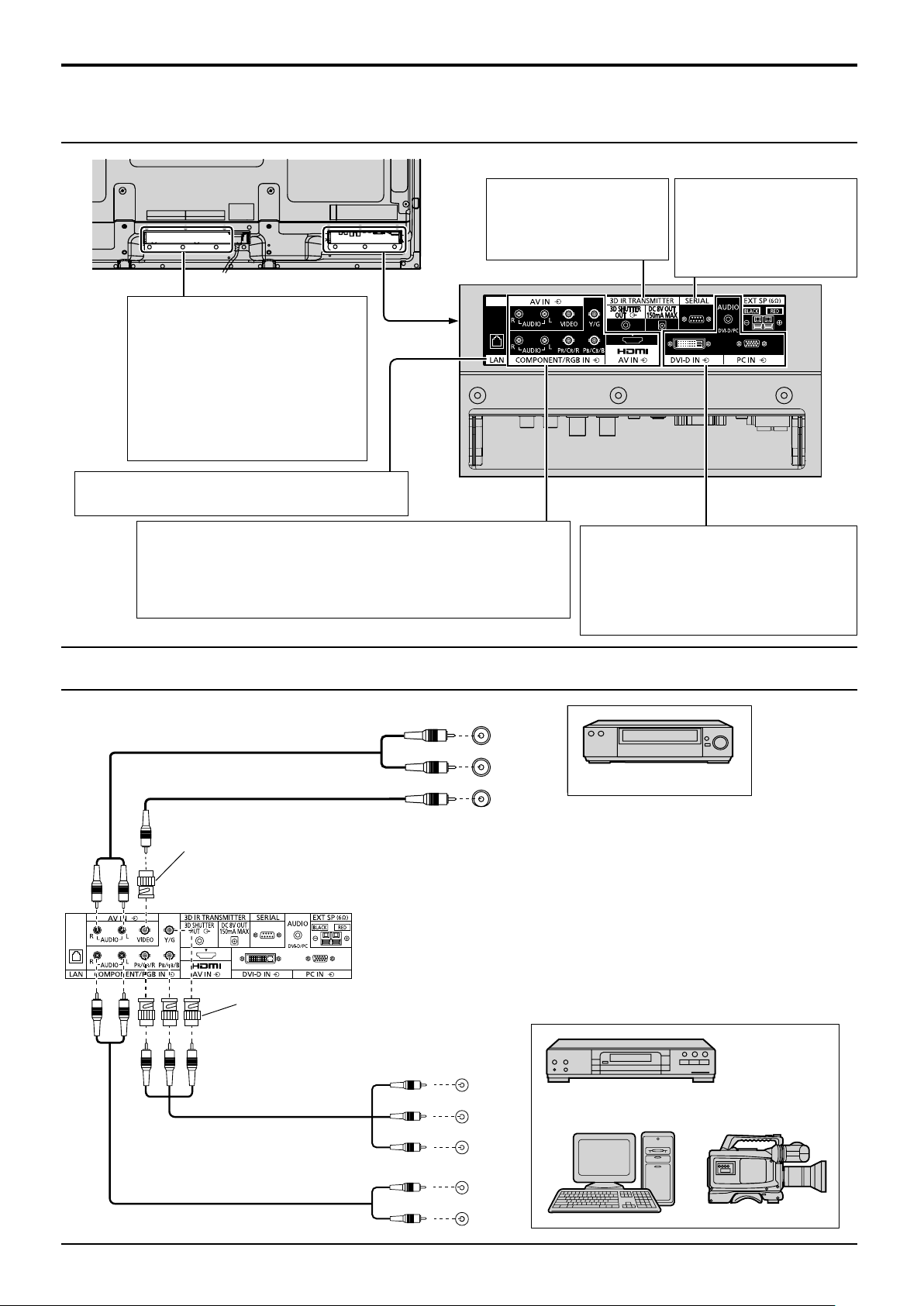
Video equipment connection
Connections
SLOT: Terminal board (optional
accessories) insert slot (see
page 4)
Note:
The right side slot is for factory
use only. The terminal board with
1-slot width does not function
when installed in the right side
slot.
LAN: Connect to a network to control the unit.
(see page 65)
AV IN (VIDEO): Composite Video Input Terminal (see below)
COMPONENT/RGB IN: Component/RGB Video Input Terminal
(see below)
AV IN (HDMI): HDMI Input Terminal (see page 12)
Connect to video equipment such as VCR or DVD player.
3D IR TRANSMITTER:
Connect the 3D IR
TRANSMITTER
(optional accessory).
DVI-D IN: DVI-D Input Terminal
PC IN:
PC Input Terminal
Connect to video terminal of PC
or equipment with Y, PB(CB) and
PR(CR) output (see page 13).
SERIAL:
Terminals are on the
bottom side of the
Plasma Display.
(see page 12)
Control the
Plasma Display
by connecting
to PC (see
page 14)
VIDEO and COMPONENT / RGB IN connection
Note:
Additional equipment, cables and adapter plugs
shown are not supplied with this set.
RCA-BNC
Adapter plug
RCA-BNC
Adapter plug
Notes:
• Change the “Component/RGB-in select” setting in the “Setup”
menu to “Component” (when Component signal connection) or
“RGB” (when RGB signal connection). (see page 40)
• Signals input to COMPONENT/RGB IN terminals correspond to
Sync on G or Sync on Y.
Y
P B
L
AUDIO
R
OUT
VIDEO
OUT
, Y , P B , P R
OUT
P
R
Computer RGB Camcorder
VCR
DVD Player
L
R
AUDIO
OUT
11
Connections
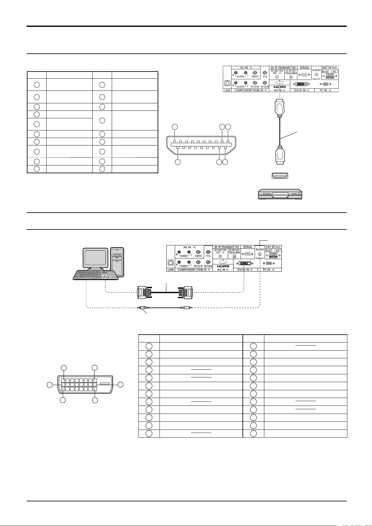
HDMI connection
[Pin assignments and signal names]
Pin No.
10
Signal name
1
T.M.D.S Data2+
T.M.D.S Data2
2
Shield
3
T.M.D.S Data2-
4
T.M.D.S Data1+
T.M.D.S Data1
5
Shield
6
T.M.D.S Data1-
7
T.M.D.S Data0+
T.M.D.S Data0
8
Shield
9
T.M.D.S Data0T.M.D.S Clock+
Pin No.
Note:
Additional equipment and HDMI cable shown are not supplied with this set.
Signal name
T.M.D.S Clock
11
Shield
12
T.M.D.S Clock-
13
CEC
Reserved
14
(N.C. on device)
15
SCL
16
SDA
DDC/CEC
17
Ground
18
+5V Power
Hot Plug Detect
19
1
19
18
3
2
4
HDMI
AV OUT
DVD player
HDMI cable
DVI-D IN connection
PC with DVI-D
video out
DVI-video cable (Within 5 m)
Stereo mini plug (M3)
DVI-D Input Connector
Pin Layouts
1
9
17
8
24
Connection port view
16
Pin No.
Signal Name
T.M.D.S. data 2-
1
T.M.D.S. data 2+
2
T.M.D.S. data 2 shield
3
4
5
DDC clock
6
DDC data
7
8
T.M.D.S. data 1-
9
T.M.D.S. data 1+
10
T.M.D.S. data 1 shield
11
12 24
Pin No.
Notes:
• Additional equipment and cables shown are not supplied with this set.
• Use the DVI-D cable complying with the DVI standard. Image deterioration may occur depending on the length or
the quality of the cable.
Shared with PC IN.
Signal Name
13
+5 V DC
14
Ground
15
Hot plug detect
16
T.M.D.S. data 0-
17
T.M.D.S. data 0+
18
T.M.D.S. data 0 shield
19
20
21
T.M.D.S. clock shield
22
T.M.D.S. clock+
23
T.M.D.S. clock-
12
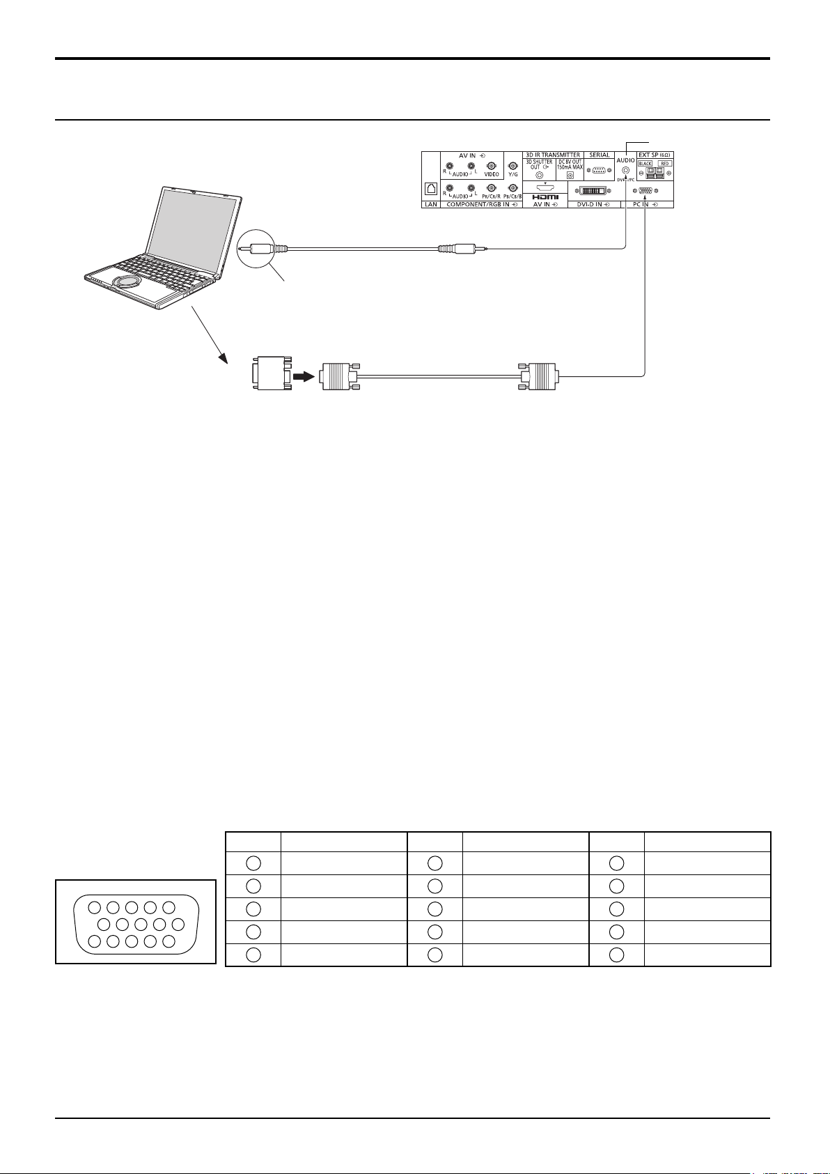
PC Input Terminals connection
COMPUTER
Connections
(Female) Shared with DVI-D IN.
Audio
Connect a cable which matches
the audio output terminal on the computer.
Conversion adapter
(if necessary)
Stereo mini plug (M3)
Mini D-sub 15p
RGB
PC cable
(Male)
Notes:
• With regard to the typical PC input signals that are described in the applicable input signals list (see page 72), adjustment
values such as for the standard picture positions and sizes have already been stored in this unit. You can add up to eight
PC input signal types that are not included in the list.
• Computer signals which can be input are those with a horizontal scanning frequency of 15 to 110 kHz and vertical scanning
frequency of 48 to 120 Hz. (However, the image will not be displayed properly if the signals exceed 1,200 lines.)
• The display resolution is a maximum of 1,440 × 1,080 dots when the aspect mode is set to “4:3”, and 1,920 × 1,080
dots when the aspect mode is set to “16:9”. If the display resolution exceeds these maximums, it may not be possible
to show fi ne detail with suffi cient clarity.
• The PC input terminals are DDC2B-compatible. If the computer being connected is not DDC2B-compatible, you will
need to make setting changes to the computer at the time of connection.
• Some PC models cannot be connected to the set.
• There is no need to use an adapter for computers with DOS/V compatible Mini D-sub 15P terminal.
• The computer shown in the illustration is for example purposes only.
• Additional equipment and cables shown are not supplied with this set.
• Do not set the horizontal and vertical scanning frequencies for PC signals which are above or below the specifi ed
frequency range.
• Component Input is possible with the pin 1, 2, 3 of the Mini D-sub 15P Connector.
• Change the “Component/RGB-in select” setting in the “Setup” menu to “Component”
(when Component signal connection) or “RGB” (when RGB signal connection). (see page 40)
Signal Names for Mini D-sub 15P Connector
Pin No. Signal Name Pin No. Signal Name Pin No. Signal Name
1
3
4 5
2
9
10
15 14 13 12 11
1
2
3
6 7 8
4
5
R (PR/CR)
G (Y)
B (PB/CB)
NC (not connected)
GND (Ground)
Pin Layout for PC Input
Terminal
6
7
8
9
10
GND (Ground)
GND (Ground)
GND (Ground)
+5 V DC
GND (Ground)
11
NC (not connected)
12
13
14
15
HD/SYNC
SDA
VD
SCL
13
Connections
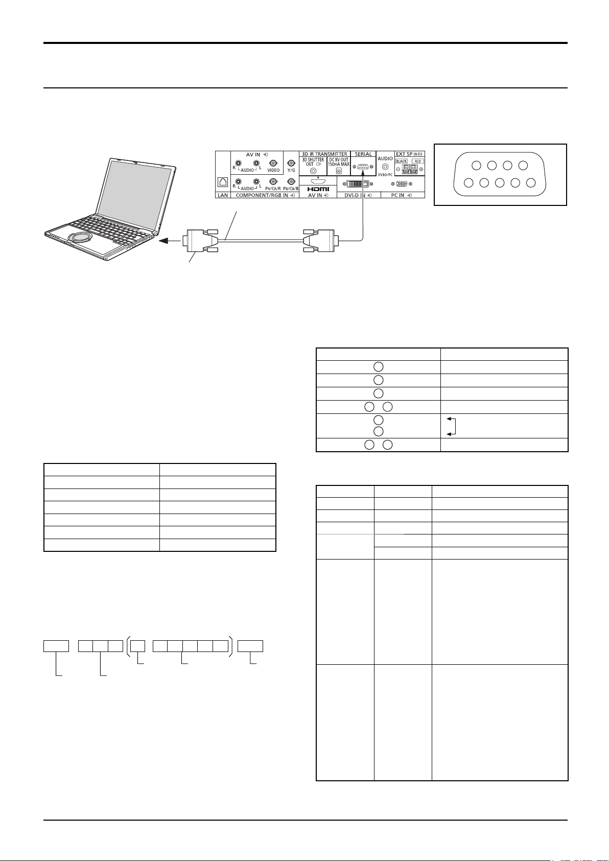
SERIAL Terminals connection
The SERIAL terminal is used when the Plasma Display is controlled by a computer.
Note: To use serial control for this unit, make sure to set the “Control I/F Select” in the “Network Setup” menu to
“RS-232C”. (see page 58)
COMPUTER
(Male)
6789
13452
RS-232C Straight cable
(Female)
D-sub 9p
Notes:
• Use the RS-232C straight cable to connect the computer to the Plasma Display.
• The computer shown is for example purposes only.
• Additional equipment and cables shown are not supplied with this set.
The SERIAL terminal conforms to the RS-232C interface
specifi cation, so that the Plasma Display can be controlled
by a computer which is connected to this terminal.
The computer will require software which allows the
sending and receiving of control data which satisfies
the conditions given below. Use a computer application
such as programming language software. Refer to the
documentation for the computer application for details.
Communication parameters
Signal level RS-232C compliant
Synchronization method Asynchronous
Baud rate 9600 bps
Parity None
Character length 8 bits
Stop bit 1 bit
Flow control -
Basic format for control data
The transmission of control data from the computer
starts with a STX signal, followed by the command, the
parameters, and lastly an ETX signal in that order. If there
are no parameters, then the parameter signal does not
need to be sent.
STX C1 C2 C3 P1 P2 P3 P4: P5 ETX
Start
(02h)
Colon Parameter(s)
3-character
command (3 bytes)
(1 - 5 bytes)
End
(03h)
Notes:
• If multiple commands are transmitted, be sure to wait for
the response for the fi rst command to come from this unit
before sending the next command.
• If an incorrect command is sent by mistake, this unit will
send an “ER401” command back to the computer.
• S1A and S1B of Command IMS are available only when
a dual input terminal board is attached.
• Consult your local Panasonic dealer for detail instructions
Signal names for D-sub 9P connector
Pin No. Details
2
3
5
4
6
•
7
8
1
9
•
These signal names are those of computer specifi cations.
Command
Command Parameter Control details
PON None Power ON
POF None Power OFF
AVL ** Volume 00 - 63
AMT
IMS None
DAM None
0 Audio MUTE OFF
1 Audio MUTE ON
SL1
S1A
S1B
VD1
YP1
HM1
DV1
PC1
ZOOM
FULL
JUST
NORM
ZOM2
ZOM3
SJST
SNOM
SFUL
14:9
With the power off, this display responds to PON command
only.
on command usage.
Pin layout for SERIAL Terminal
R X D
T X D
GND
Non use
(Shorted in this set)
NC
Input select (toggle)
SLOT input (SLOT INPUT)
SLOT input (SLOT INPUT A)
SLOT input (SLOT INPUT B)
VIDEO input (VIDEO)
COMPONENT/RGB IN input
(COMPONENT)
HDMI input (HDMI)
DVI-D IN input (DVI)
PC IN input (PC)
Screen mode select (toggle)
Zoom, Zoom1
16:9
Just, Just1 (For Video/SD/HD signal)
4:3, 4:3 (1)
Zoom2 (For Video/SD/HD signal)
Zoom3 (For Video/SD/HD signal)
Just2 (For HD signal)
4:3 (2) (For HD signal)
4:3 Full (For HD signal)
14:9 (For Video/SD/HD signal)
14
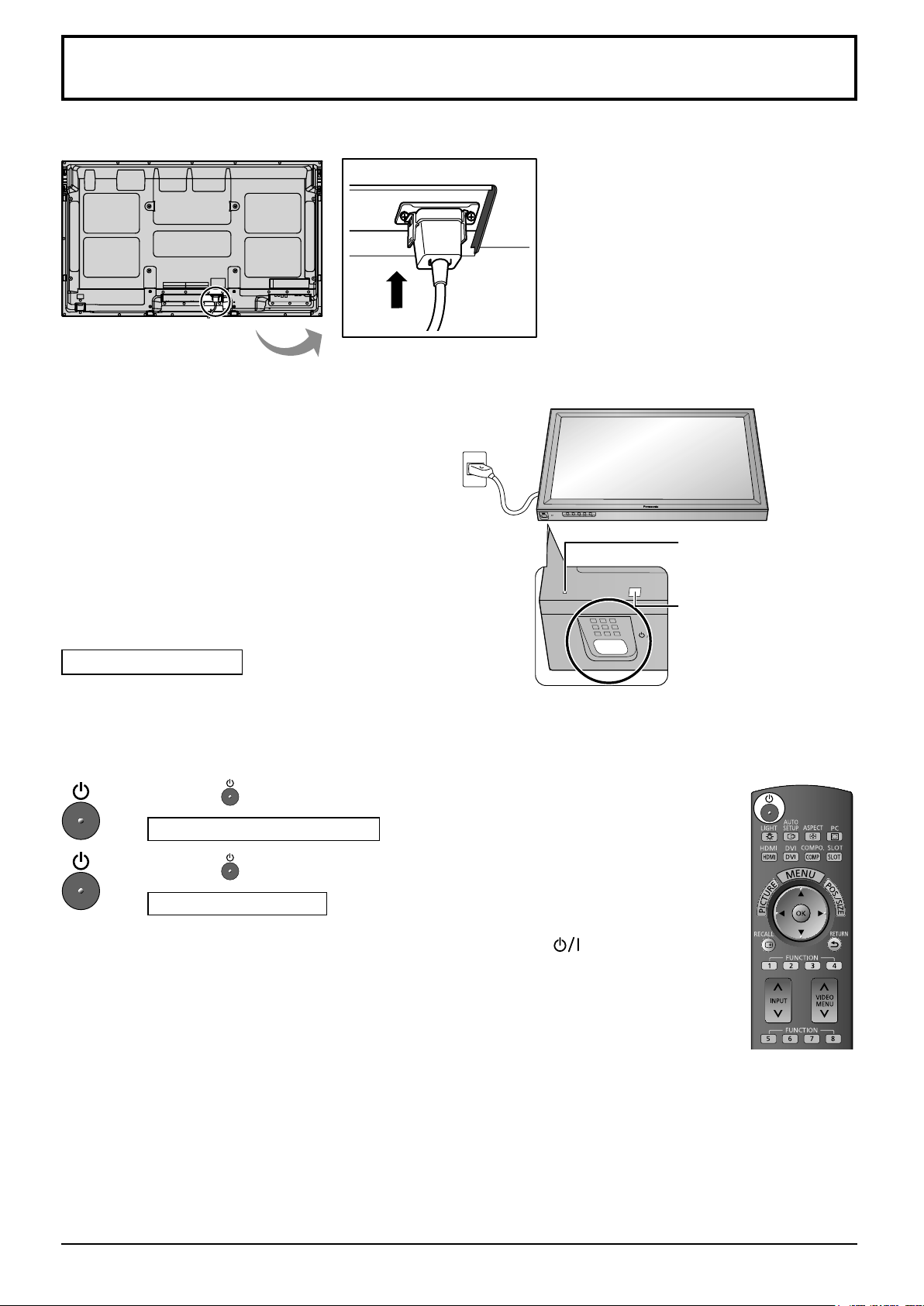
Power On / Off
Connecting the AC cord plug to the Plasma Display.
Connecting the plug to the Wall Outlet
Notes:
• Main plug types vary between countries. The power
plug shown at right may, therefore, not be the type
fi tted to your set.
• When disconnecting the AC cord, be absolutely
sure to disconnect the AC cord plug at the socket
outlet fi rst.
INPUT MENU ENTER/+/VOL-/
Power Indicator
Press the Power switch on the Plasma Display to
turn the set on: Power-On.
Power Indicator: Green
Press the
Power Indicator: Red (standby)
Press the button on the remote control to turn the Plasma Display on.
Power Indicator: Green
Turn the power to the Plasma Display off by pressing the switch on the
unit, when the Plasma Display is on or in standby mode.
Note:
During operation of the power management function, the power indicator turns
orange in the power off state.
button on the remote control to turn the Plasma Display off.
Remote Control Sensor
15
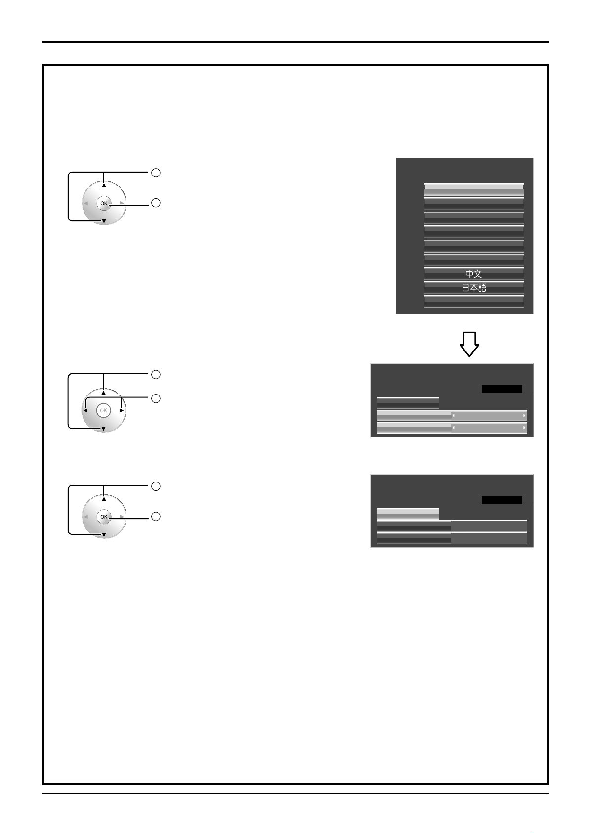
Power On / Off
When fi rst switching on the unit
Following screen will be displayed when the unit is turned on for the fi rst time.
Select the items with the remote control. Unit buttons are invalid.
OSD Language
Day/Time Setup
1
Select the language.
2
Set.
1
Select “Day” or “Time”.
2
Setup “Day” or “Time”.
OSD Language
Day/Time Setup
Set
Time
English (UK)
Deutsch
Français
Italiano
Español
ENGLISH (US)
Русский
Time MON 99:99
MONDay
99:99
1
Select “Set”.
2
Set.
Day/Time Setup
Set
Day
PRESENT TIME OF DAY
PRESENT TIME OF DAY
Time MON 99:99
Notes:
• Once the items are set, the screens won't be displayed when switching on the unit next time.
• After the setting, the items can be changed in the following menus.
OSD Language (see page 43)
Day/Time Setup (see page 57)
MON
99:99
99:99Time
99:99
16

Power On / Off
Power ON warning message
The following message may be displayed when turning the unit power ON:
3D Safety Precautions
When 3D images will be viewed by unspecifi ed number of
people or used for commercial applications, someone in
authority should convey the following precautions.
These precautions should be followed in the home as well.
3D Viewing/ 3D Content/ Viewing distance/ 3D Eyewear
recommendations
- To enjoy 3D images safely and comfortably, please
read the Operating Instructions fully.
Activate 3D Safety Precautions if you deliver 3D images to unspecifi ed audiences for business or other purposes.
If “3D Function” in “3D Settings” is set to “On”, a warning message is displayed every time the power is
turned ON. (see page 44)
No activity power off Precautions
’No activity power off’ is enabled.
If “No activity power off” in Setup menu is set to “Enable”, a warning message is displayed every time
the power is turned ON. (see page 42)
These message displays can be set with the following menu: Options menu
3D Safety Precautions (see page 61)
Power On Message (see page 61)
17
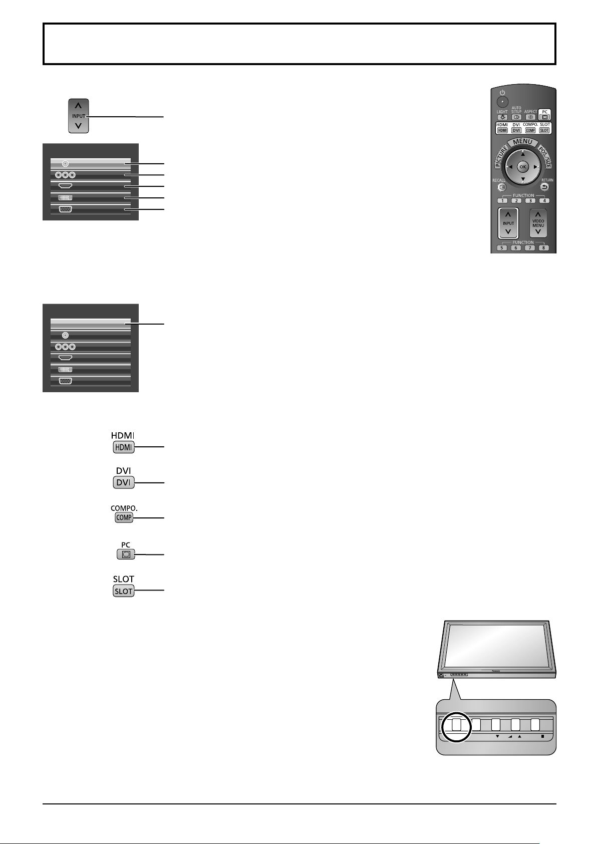
Selecting the input signal
INPUT MENU ENTER/ + / VOL - /
Press to select the input signal to be played back from the equipment
which has been connected to the Plasma Display.
INPUT
VIDEO
COMPONENT
HDMI
DVI
PC
When an optional Terminal Board is installed:
INPUT
SLOT INPUT
VIDEO
COMPONENT
HDMI
DVI
PC
Video input terminal in AV IN (VIDEO).
Component or RGB input terminal in COMPONENT/RGB IN.*
HDMI input terminal in AV IN (HDMI).
DVI input terminal in DVI-D IN.
PC input terminal in PC IN.
* “COMPONENT” may be displayed as “RGB” depending on the
setting of “Component/RGB-in select”. (see page 40)
Input terminal in Terminal Board
When a dual input Terminal Board is installed, “SLOT INPUT A” and “SLOT INPUT B”
are displayed.
Using dedicated buttons for input selection
Press to select HDMI signal terminals in HDMI.
Press to select DVI signal terminal in DVI-D IN.
Press to select component or RGB signal terminal in COMPONENT/RGB IN.
Press to select PC signal terminal in PC IN.
Press to select Input terminal in Terminal Board.
For a dual input terminal board, pressing it allows selection between “SLOT INPUT A”
and “SLOT INPUT B”.
Notes:
• Selecting is also possible by pressing the INPUT button on the unit.
• Select to match the signals from the source connected to the component/
RGB input terminals. (see page 40)
• Image retention (image lag) may occur on the plasma display panel
when a still picture is kept on the panel for an extended period. The
function that darkens the screen slightly is activated to prevent image
retention (see page 70), but this function is not the perfect solution to
image retention.
INPUT MENU ENTER/+/VOL-/
18
INPUT MENU ENTER/
+
/VOL
-
/
Basic Controls
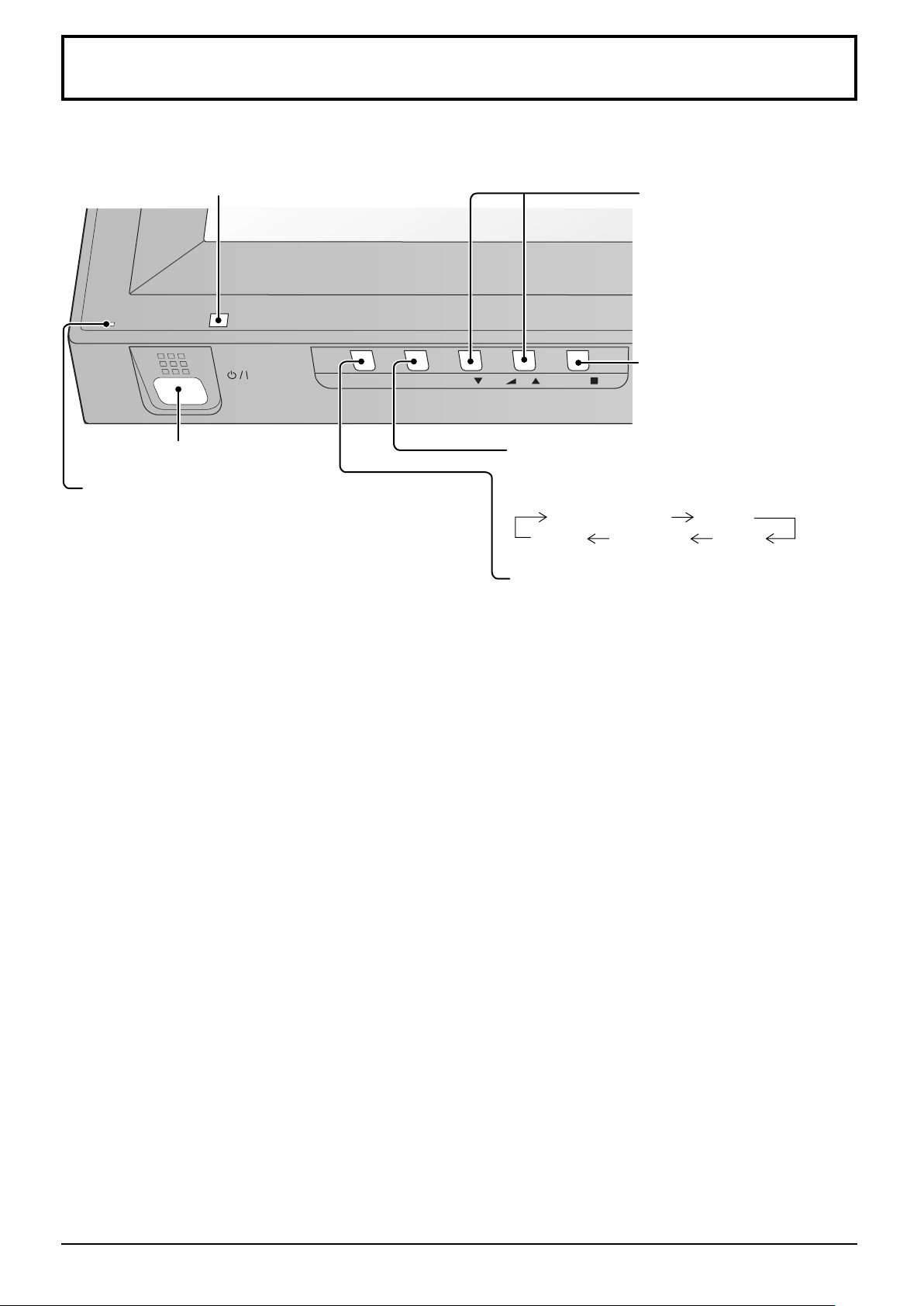
Main Unit
Remote control sensor
Main Power On / Off Switch
Power Indicator
The Power Indicator will light.
• Power-OFF .... Indicator not illuminated (The unit will
still consume some power as long as
the power cord is still inserted into the
wall outlet.)
• Standby ........ Red
Orange (When “Slot power” is set to
“On”. See page 60)
Orange (Depending on the type of
the function board installed, when the
power is supplied to the slot)
Orange (When “Control I/F Select” is
set to “LAN”. See page 58)
• Power-ON ...... Green
• PC Power management (DPMS)
.......................Orange (With PC input signal.
See page 42)
• DVI-D Power management
.......................Orange (With DVI input signal.
See page 42)
Volume Adjustment
Volume Up “+” Down “–”
When the menu screen is
displayed:
“+” : press to move the cursor up
“–” :
press to move the cursor down
(see page 25)
Enter / Aspect button
(see page 21, 25)
MENU Screen ON / OFF
Each time the MENU button is pressed, the menu
screen will switch. (see page 25)
Normal Viewing Picture
Sound Pos./Size Setup
INPUT button
(INPUT signal selection)
(see page 18)
19
Basic Controls
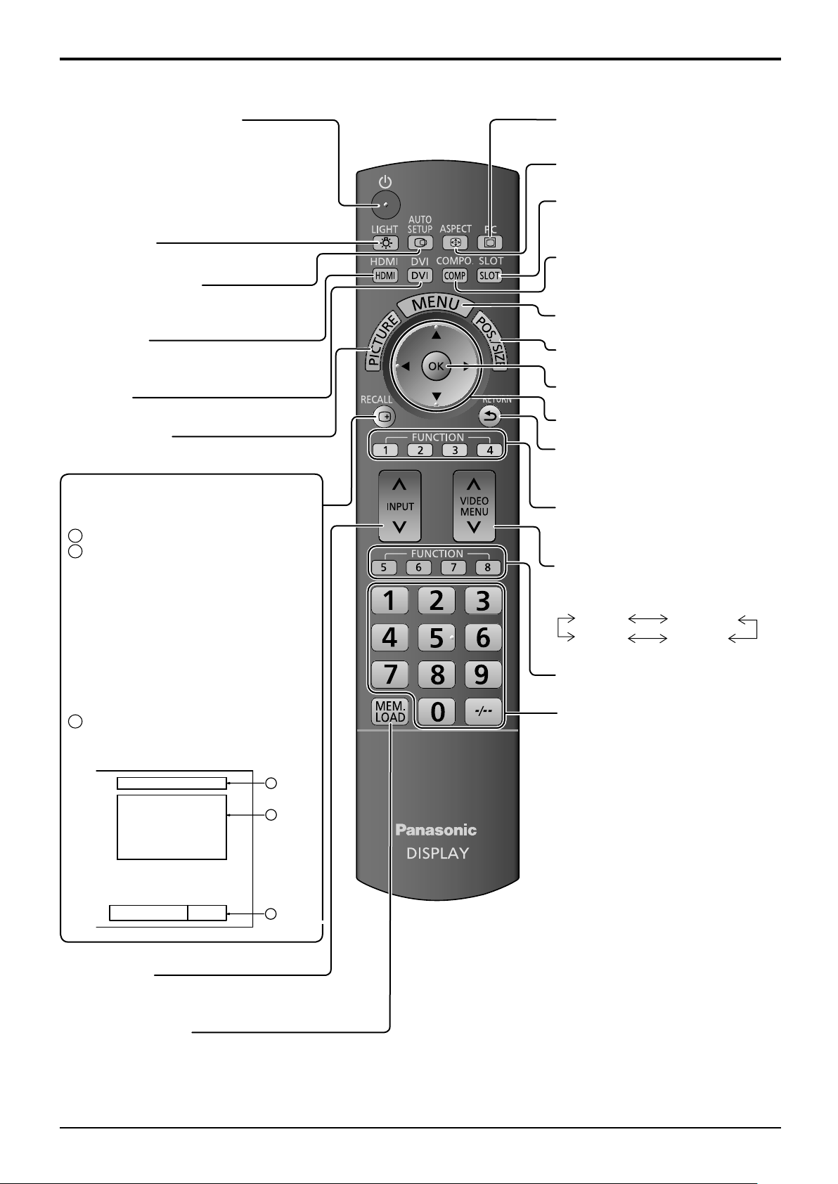
Remote Control Transmitter
Standby (ON / OFF) button
The Plasma Display must fi rst be plugged
into the wall outlet and turned on at the power
switch (see page 15).
Press this button to turn the Plasma Display
On, from Standby mode. Press it again to turn
the Plasma Display Off to Standby mode.
LIGHT button
The remote control’s buttons illuminate.
AUTO SETUP button
Automatically adjusts the position/ size
of the screen. (see page 27)
HDMI button
Press to select HDMI input.
(see page 18)
DVI button
Press to select DVI-D input. (see page 18)
PICTURE button
(see page 29)
RECALL button
Press the “RECALL” button to display
the current system status.
Input label
1
2
Aspect mode (see page 21)
During 3D images (see page 44)
Audio input (see page 62)
Profi le name (see page 37)
NANODRIFT Saver operating
(see page 54)
Mode of RGB/MONO settings
(see page 50)
Mode of HV Delay (see page 28)
3D Colour Compensation: Off
(see page 44)
Off timer
3
The off timer indicator is displayed
only when the off timer has been set.
PC button
Press to select PC input. (see page 18)
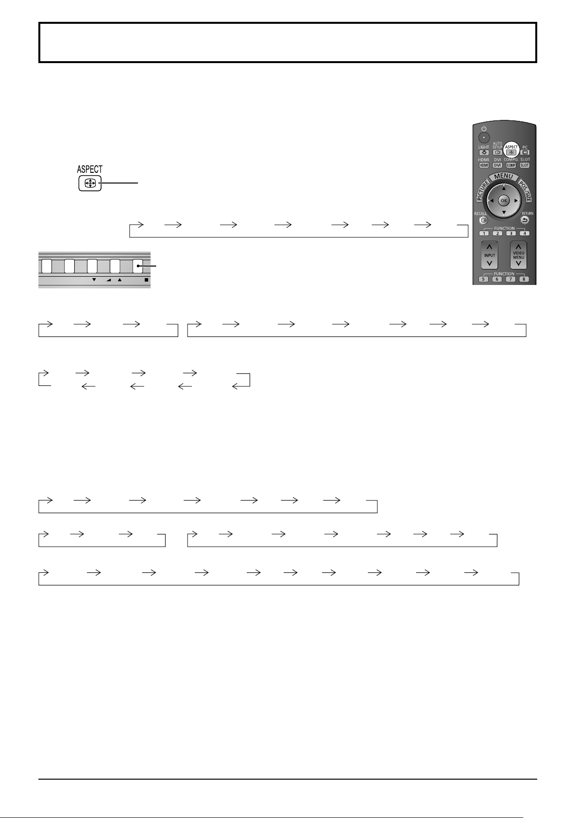
ASPECT button
Press to adjust the aspect. (see page 21)
SLOT buttons
Press to select SLOT Terminal
Board. (see page 18)
COMPO. button
Press to select Component or RGB
input. (see page 18)
MENU button
Displays menu screen. (see page 25)
POS. /SIZE button
(see page 26)
OK button
Press to make selections.
Cursor buttons
RETURN button (see page 25)
Press the RETURN button to return
to previous menu screen.
FUNCTION buttons
(see page 63)
VIDEO MENU button
Press to select Picture Mode.
(see page 30)
Normal
Monitor
Dynamic
Cinema
FUNCTION buttons
(see page 63)
Numeric buttons
(see page 37)
PC
3D
♪ COMPONENT
Memory name: Memory2
3D Colour Compensation Off
4:3
NANODRIFT
R Off
H Delay
Off timer 90min
1
2
3
INPUT button
Press to select input signal sequentially.
(see page 18)
MEM. LOAD button
(see page 37)
20
INPUT MENU ENTER/ +/ VOL -/
ASPECT Controls
The Plasma Display will allow you to enjoy viewing the picture at its maximum size, including wide screen cinema
format picture.
Note:
Be aware that if you put the display in a public place for commercial purposes or a public showing
and then use the aspect mode select function to shrink or expand the picture, you may be violating
the copyright under copyright law. It is prohibited to show or alter the copyrighted materials of other
people for commercial purposes without the prior permission of the copyright holder.
Press repeatedly to move through the aspect options:
For details about the aspect mode, please see “List of Aspect Modes” (page 71).
For VIDEO (S VIDEO) signal input:
4:3 Zoom1 16:9Zoom2 Zoom3 14:9 Just
[from the unit]
The aspect mode changes each time the ENTER button is pressed.
For PC signal input: For SD signal input (525 (480) / 60i • 60p, 625 (575) / 50i • 50p):
4:3 Zoom 16:9
4:3 Zoom1 16:9Zoom2 Zoom3 14:9 Just
For HD signal input [1125 (1080) / 60i • 50i • 60p • 50p • 24p • 25p • 30p • 24sF, 1250 (1080) / 50i,
750 (720) / 60p • 50p]:
4:3
[For 3D images]
The aspect is fi xed as “16:9” and you cannot switch.
All Aspect mode
Set “All Aspect” to “On” in Options menu to enable the extended aspect mode (page 60). When All Aspect mode, the aspect
mode of pictures is switched as follows. For details about the aspect mode, please see “List of Aspect Modes”. (page 71)
For VIDEO (S VIDEO) signal input:
4:3 Zoom1 16:9Zoom2 Zoom3 14:9 Just
For PC signal input:
4:3 Zoom
For HD signal input [1125 (1080) / 60i • 50i • 60p • 50p • 24p • 25p • 30p • 24sF, 1250 (1080) / 50i, 750 (720) / 60p • 50p]:
4:3 Full Zoom1 16:9 Just1Zoom2 Zoom3 14:9 Just2 4:3 (1) 4:3 (2)
4:3 Full Zoom1
14:9Just
16:9
16:9
Zoom2
Zoom3
For SD signal input (525 (480) / 60i
4:3 Zoom1 16:9 JustZoom2 Zoom3 14:9
Notes:
• The aspect mode is memorized separately for
each input terminal.
• Do not allow the picture to be displayed in 4:3
mode for an extended period, as this can cause
a permanent image retention to remain on the
Plasma Display Panel.
•
60p, 625 (575) / 50i
•
50p):
21
INPUT MENU ENTER/ +/ VOL -/
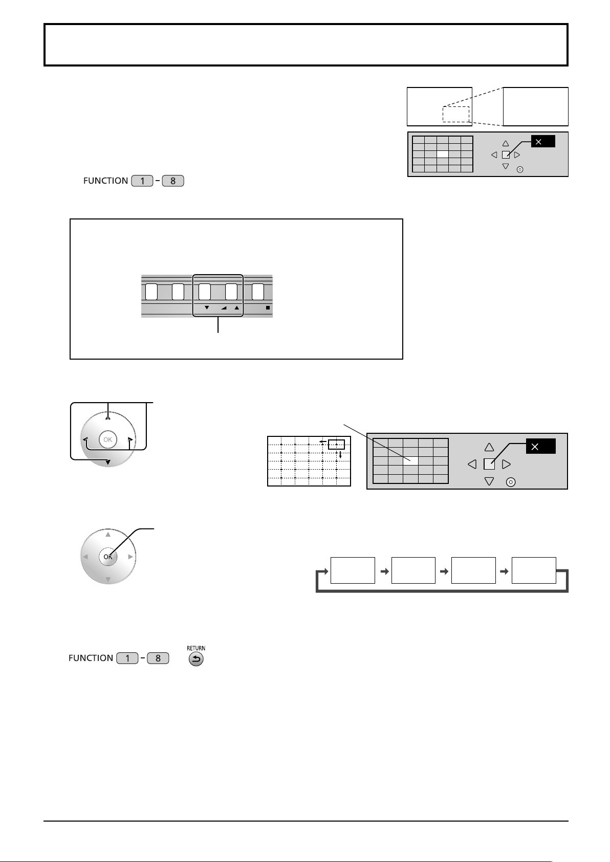
Digital Zoom
This displays an enlargement of the designated part of the displayed image.
To use this function, go to “Function Button Settings” in the Setup menu and
set this function to the FUNCTION button (see page 56).
Display the operation guide.
1
Press to access Digital Zoom.
The operation guide will be displayed.
During Digital Zoom, only the following buttons can be operated.
[Unit]
VOL button
Select the area of the image to be enlarged.
2
Press on the enlargement location to select.
1
Exit
The cursor will move.
Select the magnifi cation required for the enlarged display.
3
Each time this is pressed, the magnifi cation factor changes.
This is shown in the image being displayed.
s1
Return to normal display (quit Digital Zoom).
4
or
Notes:
• When power goes OFF (including “Off Timer” operation), Digital Zoom terminates.
• The Digital Zoom function cannot be selected while in the following operation state:
When Screensaver is running (see page 51).
• While Digital Zoom is in operation, “Adjusting Pos./Size” cannot be used.
Press to exit from the Digital Zoom.
s2
s3
22
Exit
s4
22

Viewing 3D images
You can enjoy viewing 3D images with contents or programmes compatible with 3D effect by using the 3D eyewear
(optional).
Note:
You need the 3D IR TRANSMITTER (optional) and the 3D eyewear (optional) to view the 3D images on this display.
For further information, see the instruction manuals of the 3D IR TRANSMITTER and the 3D eyewear.
This display supports “Frame Sequential
*
1:
The 3D format that the images for the left and right eyes are recorded with the high defi nition quality and alternately played back
*
2, *3: See “Table of images that can be seen for each 3D Picture Format and the source image format” on page 24.
*
4: To view “Simultaneous” 3D images, one of the following terminal boards should be installed:
Dual HD-SDI Terminal Board for 3D (TY-FB30DHD3D), Dual DVI-D Terminal Board for 3D (TY-FB30DD3D)
To view the 3D images
To view the contents of the Frame Sequential format (ex. 3D-compatible Blu-ray Disc, etc.) with 3D effect
Connect the 3D-compatible player via an HDMI cable (see page 12) and playback the contents.
• Use fully wired HDMI compliant cable.
• For the settings of the player, read the manual of the player.
• If you use the non 3D-compatible player, the images will be displayed without 3D effect.
To view the contents of 3D formats other than Frame Sequential with 3D effect.
Match the picture format in “3D Picture Format” (see page 44) before viewing.
• You can view “Side by Side” and “Top and Bottom” with 3D effect even if you use the non 3D-compatible player.
• Please consult the suppliers of contents or programmes for availability of this service.
Turn the 3D Eyewear on
• See the instruction manual of 3D eyewear for handling.
Put on the 3D Eyewear
Watch the 3D images
*1
”, “Side by Side*2”, “Top and Bottom*3” and “Simultaneous*4” 3D formats.
Notes:
• If the room is lit by fl uorescent lights and light appears to fl icker when using the 3D Eyewear, switch off the
fl uorescent light. Alternatively, please set “3D Refresh Rate” to “100Hz” or “120Hz” whichever reduces fl icker.
(see page 46)
• 3D content will not be correctly visible if the 3D Eyewear is worn upside down or back-to-front.
• Do not wear the 3D Eyewear when watching anything other than 3D images. Liquid crystal displays (such as
computer screens, digital clocks or calculators, etc.) may be diffi cult to see while wearing the 3D Eyewear.
• Do not use the 3D Eyewear as sunglasses.
• 3D effects may be perceived differently depending on the person.
23
 Loading...