


y
A
A
Y
Y
A
ORDER NO. MTNC070411CE
D34 Canada: D10
High Definition Hospitality Plasma Display
TH-37PR10U
TH-42PR10U
GPH10D Chassis
Specifications
Power Source 120 VAC, 50/60Hz
Power Consumption
Power on 340 W (37 inch) 380 W (42 inch)
Stand-bycondition Save OFF 0.7 W, Save ON 0.5 W (37 inch) Save OFF 0.7 W, Save ON 0.5 W (42 inch)
Power off condition 0.2 W (37 inch) 0.2 W (42 inch)
Plasma Displaypanel Drive method:AC type 37-inch, Drive method:AC type 42-inch,
16:9 aspect ratio (37 inch) 16:9 aspect ratio (42 inch)
Screen size 32.2" (819 mm) (W) × 18.0" (457 mm) (H) × 37" (938 mm) (diagonal) (37 inch)
36.3" (922 mm) (W) × 20.4" (518 mm) (H) × 42" (1,057 mm) (diagonal) (42 inch)
(No. of pixels) 737,280 (1,024 (W) × 720(H)) (37 inch) 786,432 (1,024 (W) × 768(H)) (42 inch)
[3,072 × 720 dots] (37 inch) [3,072 × 768 dots] (42 inch)
Operating condition
Temperature 32 °F - 104 °F (0 °C - 40 °C)
Humidit
Applicablesignals
Scanning format 525 (480) / 60i 60p, 625 (575)/50i 50p, 750 (720)/60p 50p, 1125 (1080) / 60i 50i 24p 25p
PC signals VGA, SVG
Connection terminals
PC IN (HIGH-DENSITYMINI-D-SUB 15PIN)
20% - 80%
30p 24sF.... SMPTE274M, 1250 (1080) / 50i
VGA, SVGA, XG
XGA, SXGA, UXGA..... (compressed) (37 inch) SXGA, UXGA..... (compressed) (42 inch)
Horizontal scanning frequency 15 - 110 kHz
(37 inch)
Vertical scanning frequency 48 - 120 Hz (37 inch) Vertical scanning frequency 48 - 120 Hz (42 inch)
B/P
R/P
HD/VD :1.0 - 5.0 Vp-p (high impedance)
UDIO IN (M3 JACK) 0.5 Vrms (high impedance)
Horizontal scanning frequency 15 - 110 kHz
(42 inch)
or G with/sync1.0 Vp-p (75-ohm)
or G without / sync0.7 Vp-p (75-ohm)
:0.7 Vp-p (75-ohm)
B/CB
:0.7 Vp-p (75-ohm)
R/CR
© 2007 Matsushita Electric Industrial Co., Ltd. All
rights reserved. Unauthorized copying and
distribution is a violation of law.
A
TH-37PR10U / TH-42PR10U
SERIAL EXTERNAL CONTROL TERMINAL (D-SUB 9PIN) RS-232C COMPATIBLE
Accessories Supplied
Fixing bands TMME203 × 2
Dimensions (W×H×D) 36.1" (917 mm) × 25.4" (644 mm) × 3.7" (95 mm)
(4.3”(109mm)when including protruding portion of
slots)(37 inch)
Mass (weight) approx. 55.1 lbs (37 inch) approx. 61.7 lbs (42 inch)
Sound
Speaker 4.8” (120mm) × 2.4” (60mm) × 2 pcs , 8-ohm
udio Output 20W〔10W+10W〕(10%THD)
40.2" (1,020 mm) ×27.8" (705 mm) × 3.7" (95 mm)
(4.3”(109mm)when including protruding portion of
slots)(42 inch)
Notes:
· Design and specifications are subject to change without notice. Mass and dimensions shown are approximate.
CONTENTS
Page Page
1 Applicable signals 4
2 Safety Precautions
2.1. General Guidelines
3 Prevention of Electrostatic Discharge (ESD) to
Electrostatically Sensitive (ES) Devices
4 About lead free solder (PbF)
5 Service Hint
6 Disassembly TH-37PR10U
6.1. Removal of Rear Cover
6.2. Removal of Slot Block
6.3. Removal of DS-Board
6.4. Removal of HX-Board
6.5. Removal of Speaker(L, R)
6.6. Removal of DN-Board
6.7. Removal of P-Board
6.8. Removal of D-Board
6.9. Removal of SU-Board and SD-Board
6.10. Removal of SC-Board
6.11. Removal of SS-Board
6.12. Removal of C1, C2-Board
6.13. Removal of S-Board
6.14. Removal of GK-Board
6.15. Removal of K-Board
6.16. Removal of Escutcheon and the Front Glass
6.17. Removal of Plasma Panel
7 Disassembly TH-42PR10U
7.1. Removal of Rear Cover
7.2. Removal of Slot Block
7.3. Removal of DS-Board
7.4. Removal of HX-Board
7.5. Removal of Speaker(L, R)
7.6. Removal of DN-Board
10
10
10
11
11
11
12
12
12
13
14
14
14
16
18
18
18
18
19
19
19
5
5
6
7
8
9
9
9
9
7.7. Removal of P-Board
7.8. Removal of D-Board
7.9. Removal of SU-Board and SD-Board
7.10. Removal of SC-Board
7.11. Removal of SS-Board
7.12. Removal of C1, C2-Board
7.13. Removal of S-Board
7.14. Removal of GK-Board
7.15. Removal of K-Board
7.16. Removal of Escutcheon and the Front Glass
7.17. Removal of Plasma Panel
8 Location of Lead Wiring
8.1. Wiring for the 37 inch model
8.2. Wiring for the 42 inch model
9 Adjustment Procedure
9.1. Driver Set-up
9.2. Initialization Pulse Adjust
9.3. P.C.B. (Printed Circuit Board) exchange
9.4. Adjustment Volume Location
9.5. Test Point Location
10 Service mode
10.1. CAT (computer Aided Test) mode
10.2. IIC mode structure (following items value is sample data.)
11 Adjustment
11.1. RGB white balance adjustment
11.2. HD white balance adjustment
11.3. Power control adjustment
12 Trouble shooting guide
12.1. Self Check
12.2. No Power
12.3. No Picture
20
20
20
21
21
21
22
23
23
23
25
27
27
30
33
33
34
34
35
36
37
37
40
41
41
43
45
46
46
47
47
2
12.4. Local screen failure 48
13 Option Setting
14 Conduct Views
14.1. P-Board (37inch)
14.2. P-Board (42inch)
14.3. HX-Board
14.4. GK, K and S-Board
14.5. DS-Board
14.6. DN-Board
14.7. D-Board
14.8. C1-Board (37inch)
14.9. C1-Board (42inch)
14.10. C2-Board (37inch)
14.11. C2-Board (42inch)
14.12. SC-Board
14.13. SU-Board (37inch)
14.14. SU-Board (42inch)
14.15. SD-Board (37inch)
14.16. SD-Board (42inch)
14.17. SS-Board
15 Block and Schematic Diagram
15.1. Schematic Diagram Notes
15.2. Main Block Diagram (37inch)
15.3. Main Block Diagram (42 inch)
15.4. P-Board Block Diagram
15.5. P-Board (1 of 6) Schematic Diagram
15.6. P-Board (2 of 6) Schematic Diagram
15.7. P-Board (3 of 6) Schematic Diagram
15.8. P-Board (4 of 6) Schematic Diagram
15.9. P-Board (5 of 6) Schematic Diagram
15.10. P-Board (6 of 6) Schematic Diagram
15.11. HX-Board Block and Schematic Diagram
15.12. GK and K-Board Block and Schematic Diagram
15.13. DS-Board (1 of 2) Block Diagram
15.14. DS-Board (2 of 2) Block Diagram
15.15. DS-Board (1 of 5) Schematic Diagram
15.16. DS-Board (2 of 5) Schematic Diagram
15.17. DS-Board (3 of 5) Schematic Diagram
15.18. DS-Board (4 of 5) Schematic Diagram
15.19. DS-Board (5 of 5) Schematic Diagram
15.20. DN-Board (1 of 2) Block Diagram
15.21. DN-Board (2 of 2) Block Diagram
15.22. DN-Board (1 of 6) Schematic Diagram
15.23. DN-Board (2 of 6) Schematic Diagram
49
51
51
54
57
58
59
61
63
65
66
67
68
69
72
73
74
75
76
79
79
80
81
82
83
84
85
86
87
88
89
90
91
92
93
94
95
96
97
98
99
100
101
15.24. DN-Board (3 of 6) Schematic Diagram
15.25. DN-Board (4 of 6) Schematic Diagram
15.26. DN-Board (5 of 6) Schematic Diagram
15.27. DN-Board (6 of 6) Schematic Diagram
15.28. D-Board Block Diagram
15.29. D-Board (1 of 6) Schematic Diagram
15.30. D-Board (2 of 6) Schematic Diagram
15.31. D-Board (3 of 6) Schematic Diagram
15.32. D-Board (4 of 6) Schematic Diagram
15.33. D-Board (5 of 6) Schematic Diagram
15.34. D-Board (6 of 6) Schematic Diagram
15.35. C1 and C2-Board Block Diagram
15.36. C1-Board (1 of 2) Schematic Diagram (37inch)
15.37. C1-Board (2 of 2) Schematic Diagram (37inch)
15.38. C1-Board (1 of 2) Schematic Diagram (42inch)
15.39. C1-Board (2 of 2) Schematic Diagram (42inch)
15.40. C2-Board (1 of 2) Schematic Diagram (37inch)
15.41. C2-Board (2 of 2) Schematic Diagram (37inch)
15.42. C2-Board (1 of 2) Schematic Diagram (42inch)
15.43. C2-Board (2 of 2) Schematic Diagram (42inch)
15.44. SC-Board Block Diagram
15.45. SC-Board (1 of 2) Schematic Diagram
15.46. SC-Board (2 of 2) Schematic Diagram
15.47. SU and SD-Board Block Diagram
15.48. SU-Board (1 of 2) Schematic Diagram (37inch)
15.49. SU-Board (2 of 2) Schematic Diagram (37inch)
15.50. SU-Board (1 of 2) Schematic Diagram (42inch)
15.51. SU-Board (2 of 2) Schematic Diagram (42inch)
15.52. SD-Board (1 of 2) Schematic Diagram (37inch)
15.53. SD-Board (2 of 2) Schematic Diagram (37inch)
15.54. SD-Board (1 of 2) Schematic Diagram (42inch)
15.55. SD-Board (2 of 2) Schematic Diagram (42inch)
15.56. SS and S-Board Block Diagram
15.57. SS and S-Board (1 of 2) Schematic Diagram
15.58. SS and S-Board (2 of 2) Schematic Diagram
16 Parts Location
16.1. Exploded View
16.2. Cable relation
16.3. Accessories Box
17 Mechanica l Replacement Parts List
18 Replacement Parts List
18.1. Relpacement Parts List Notes
18.2. TH-37PR10U Electrical Replacement Parts List
18.3. TH-42PR10U Electrical Replacement Parts List
TH-37PR10U / TH-42PR10U
102
103
104
105
106
107
108
109
110
111
112
113
114
115
116
117
118
119
120
121
122
123
124
125
126
127
128
129
130
131
132
133
134
135
136
137
137
140
141
142
143
143
144
164
3
TH-37PR10U / TH-42PR10U
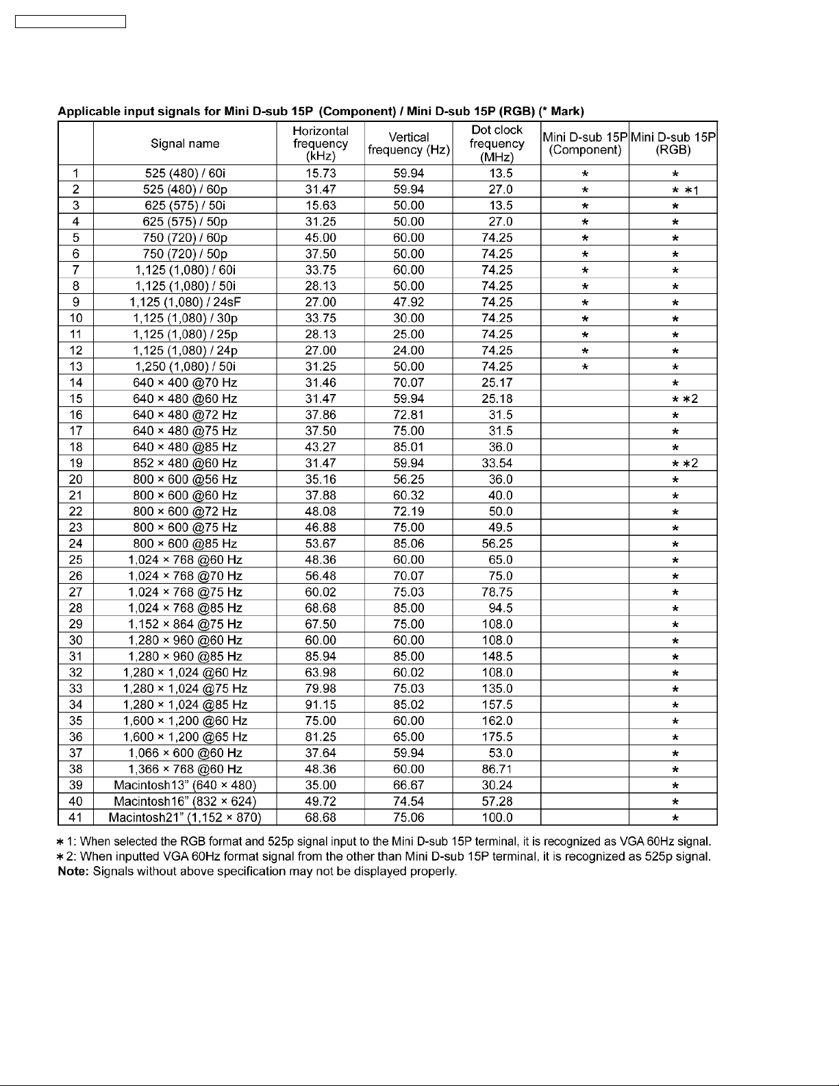
1 Applicable signals
4
TH-37PR10U / TH-42PR10U
2 Safety Precautions
2.1. General Guidelines
1. When conducting repairs and servicing, do not attempt to modify the equipment, its parts or its materials.
2. When wiring units (with cables, flexible cables or lead wires) aresupplied as repair parts and only one wire or some of the wires
have been broken or disconnected, do not attempt to repair or re-wire the units. Replace the entire wiring unit instead.
3. When conducting repairs and servicing, do not twistthe Faston connectors but plug them straight in or unplug them straight out.
4. When servicing, observe the original lead dress. If a short circuit is found, replace all parts which have been overheated or
damaged by the short circuit.
5. After servicing, see to it that all the protective devices such as insulation barriers, insulation papers shields are properly
installed.
6. After servicing, make the following leakage current checks to prevent the customer from being exposed to shock hazards.
2.1.1. Leakage Current Cold Check
1. Unplug the AC cord and connect a jumper between the two
prongs on the plug.
2. Measure the resistance value, with an ohmmeter, between
the jumpered AC plug and each exposed metallic cabinet
part on the equipment such as screwheads, connectors,
control shafts, etc. When the exposed metallic part has a
return path to the chassis, the reading should be between
1Mohm and 5.2Mohm.
When the exposed metal does not have a return path to
the chassis, the reading must be
Figure 1
.
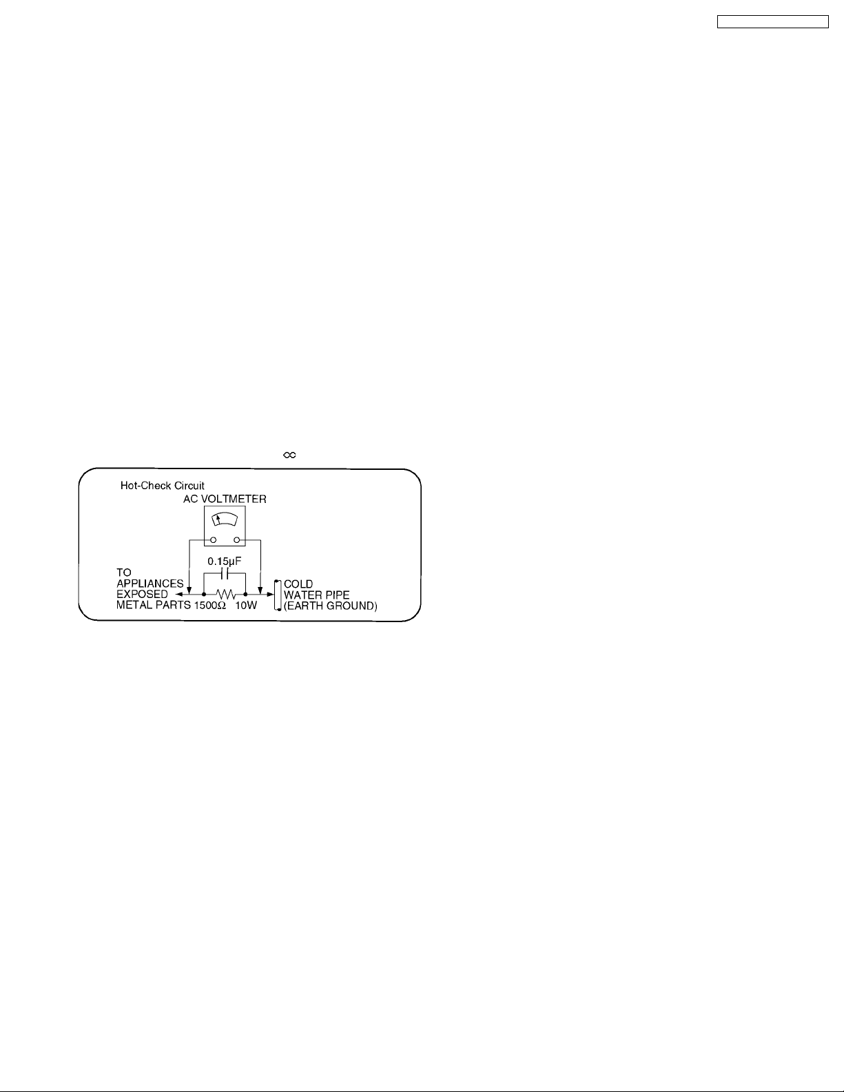
2.1.2. Leakage Current Hot Check (See
Figure 1.)
1. Plug the AC cord directly into the AC outlet. Do not use an
isolation transformer for this check.
2. Connect a 1.5kohm, 10 watts resistor, in parallel with a
0.15µF capacitors, between each exposed metallic part on
the set and a good earth ground such as a water pipe, as
shown in Figure 1.
3. Use an AC voltmeter, with 1000 ohms/volt or more
sensitivity, to measure the potential across the resistor.
4. Check each exposed metallic part, and measure the
voltage at each point.
5. Reverse the AC plug in the AC outlet and repeat each of the
above measurements.
6. The potential at any point should not exceed 0.75 volts
RMS. A leakage current tester (Simpson Model 229 or
equivalent) may be used to make the hot checks, leakage
current must not exceed 1/2 milliamp. In case a
measurement is outside of the limits specified, there is a
possibility of a shock hazard, and the equipment should be
repaired and rechecked before it is returned to the
customer.
5
TH-37PR10U / TH-42PR10U
3 Prevention of Electrostatic Discharge (ESD) to
Electrostatically Sensitive (ES) Devices
Some semiconductor (solid state) devices can be damaged easily by static electricity. Such components commonly are called
Electrostatically Sensitive (ES) Devices. Examples of typical ES devices are integrated circuits and some field-effect transistors and
semiconductor "chip" components. The following techniques should be used to help reduce the incidence of component damage
caused by electrostatic discharge (ESD).
1. Immediately before handling any semiconductor component or semiconductor-equipped assembly, drain off any ESD on your
body by touching a known earth ground. Alternatively, obtain and wear a commercially available discharging ESD wrist strap,
which should be removed for potential shock reasons prior to applying power to the unit under test.
2. After removing an electrical assembly equipped with ES devices, place the assembly on a conductive surface such as
aluminum foil, to prevent electrostatic charge buildup or exposure of the assembly.
3. Use only a grounded-tip soldering iron to solder or unsolder ES devices.
4. Use only an anti-static solder removal device. Some solder removal devices not classified as "anti-static (ESD protected)" can
generate electrical charge sufficient to damage ES devices.
5. Do not use freon-propelled chemicals. These can generate electrical charges sufficient to damage ES devices.
6. Do not remove a replacement ES device from its protective package until immediately before you are ready to install it. (Most
replacement ES devices are packaged with leads electrically shorted together by conductive foam, aluminum foil or comparable
conductive material).
7. Immediately before removing the protective material from the leads of a replacement ES device, touch the protective material
to the chassis or circuit assembly into which the device will be installed.
Caution
Be sure no power is applied to the chassis or circuit, and observe all other safety precautions.
8. Minimize bodily motions when handling unpackaged replacement ES devices. (Otherwise hamless motion such as the brushing
together of your clothes fabric or the lifting of your foot from a carpeted floor can generate static electricity (ESD) sufficient to
damage an ES device).
6
TH-37PR10U / TH-42PR10U
4 About lead free solder (PbF)
Note: Lead is listed as (Pb) in the periodic table of elements.
In the information below, Pb will refer to Lead solder, and PbF will refer to Lead Free Solder.
The Lead Free Solder used in our manufacturing process and discussed below is (Sn+Ag+Cu).
That is Tin (Sn), Silver (Ag) and Copper (Cu) although other types are available.
This model uses Pb Free solder in it’s manufacture due to environmental conservation issues. For service and repair work, we’d
suggest the use of Pb free solder as well, although Pb solder may be used.
PCBs manufactured using lead free solder will have the PbF within a leaf Symbol PbF stamped on the back of PCB.
Caution
· Pb free solder has a higher melting point than standard solder. Typically the melting point is 50 ~ 70 °F (30~40 °C) higher.
Please use a high temperature soldering iron and set it to 700 ± 20 °F (370 ± 10 °C).
· Pb free solder will tend to splash when heated too high (about 1100 °F or 600 °C).
If you must use Pb solder, please completely remove all of the Pb free solder on the pins or solder area before applying Pb
solder. If this is not practical, be sure to heat the Pb free solder until it melts, before applying Pb solder.
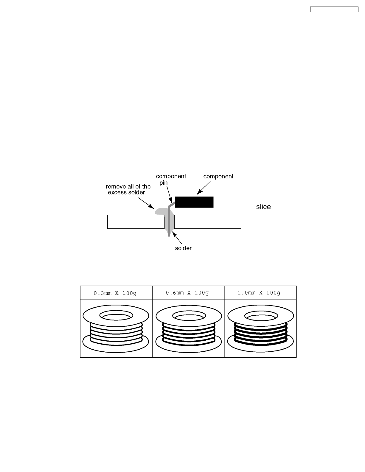
· After applying PbF solder to double layered boards, please check the component side for excess solder which may flow onto
the opposite side. (see figure below)
Suggested Pb free solder
There are several kinds of Pb free solder available for purchase. This product uses Sn+Ag+Cu (tin, silver, copper) solder.
However, Sn+Cu (tin, copper), Sn+Zn+Bi (tin, zinc, bismuth) solder can also be used.
7
TH-37PR10U / TH-42PR10U
5 Service Hint
Note:
· The remote control transmitter is not included with this set.
· Execute by the following remote control transmitter when repairing.
product number : EUR7636070R
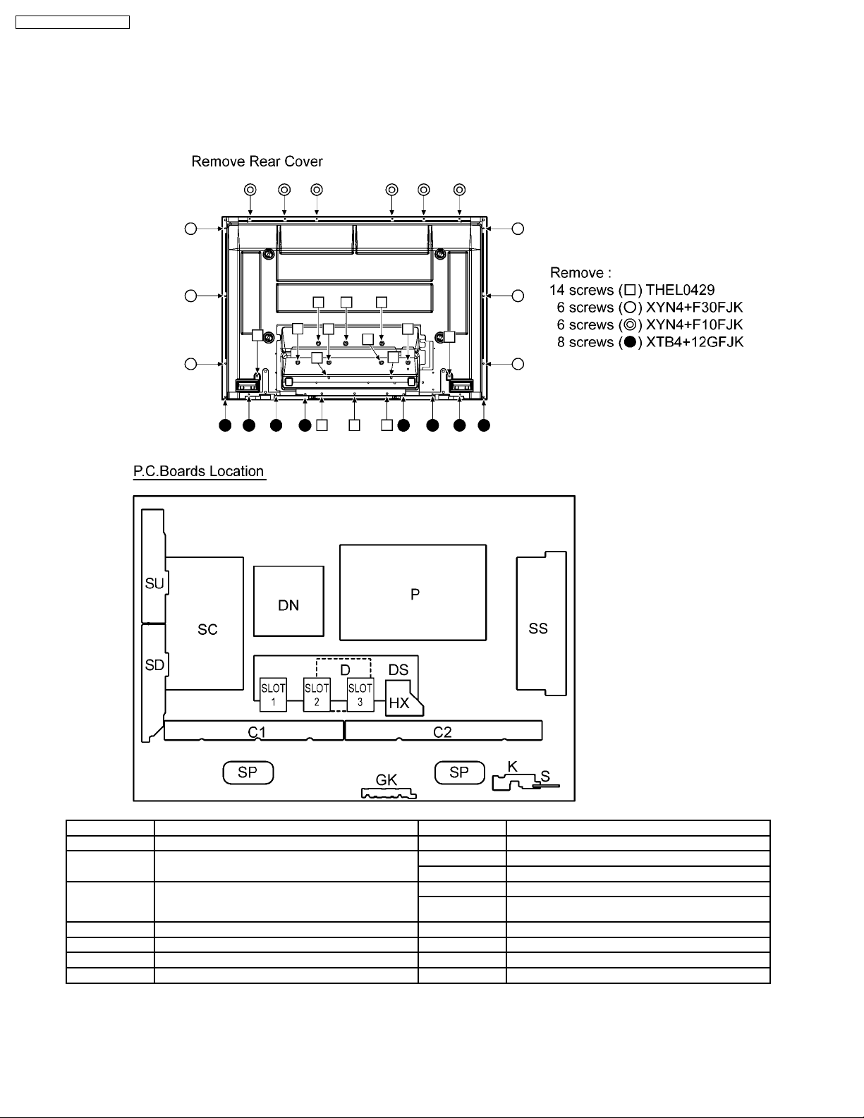
Board Name Function Board Name Function
DN Digital Signal Processor, Microcomputer C1 Data Drive (Right)
D Digital Signal Processor
Format Converter, Plasma AI Processor
DS Slot Interface (Audio / Video / Sync input Switch),
SYNC Processor, Audio Processor,
Speaker Out Amplifier, DC-DC Converter
Sustain drive SS GK Key switch
SC Scan drive P Power supply
SU Scan out (Upper) HX PC / RS-232C_Input terminal
SD Scan out (Lower)
C2 Data Drive (Left)
SP Speaker terminal
S Power switch
K Remote receiver, LED_G,R
Note:
· Extension cable kit Slot Board is supplied as service fixtures and tools.
(Parts No. TZSC0704)
8
6 Disassembly TH-37PR10U
· To disassemble P.C.B., wait for 1 minute after power was
off for discharge from electrolysis capacitors.
and marks indicate screw positions.
·
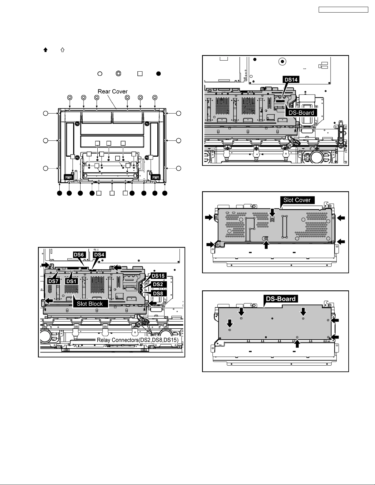
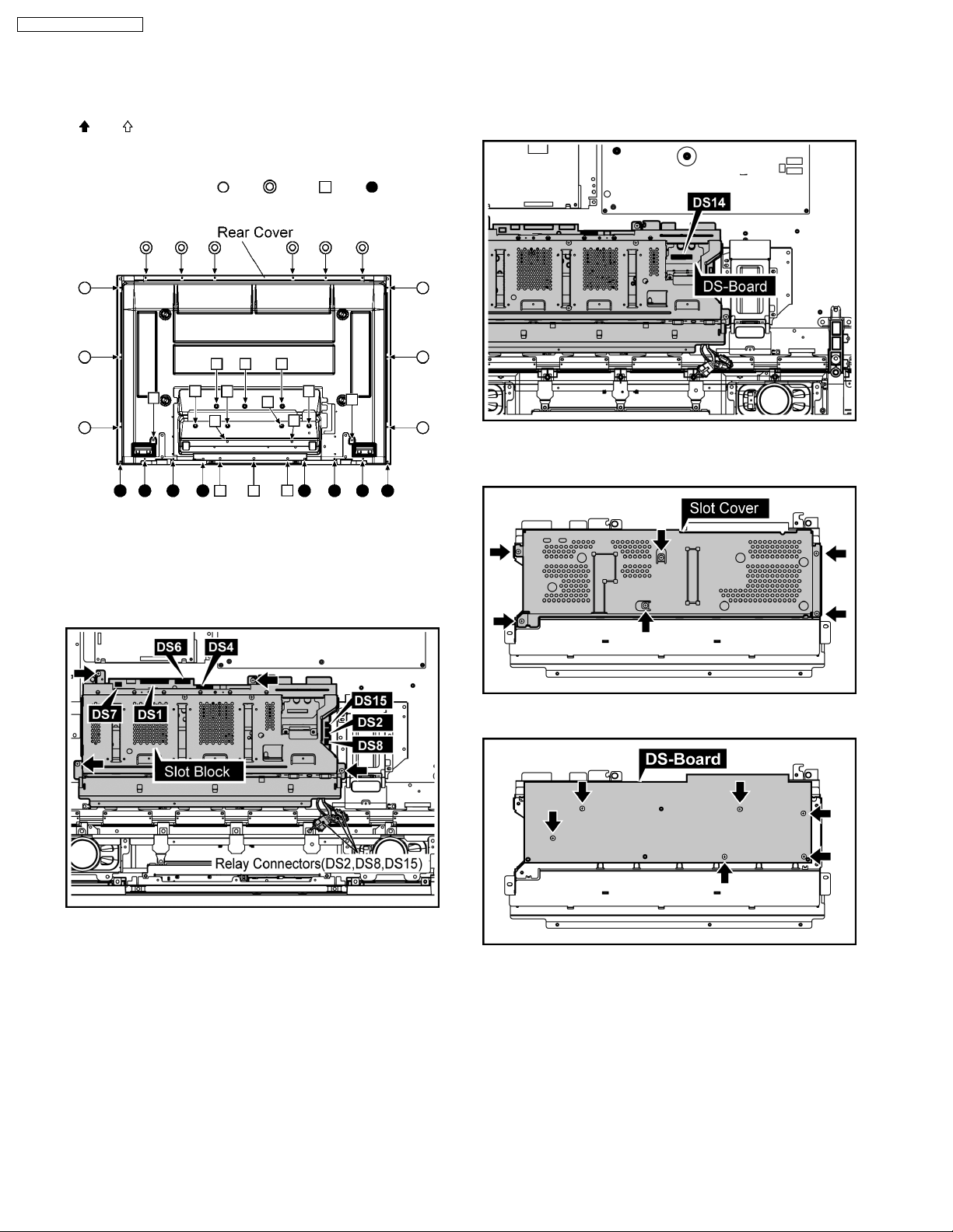
6.1. Removal of Rear Cover
1. Remove screws (×6 ,×6 , ×14 ,×8 ) and then
remove the Rear Cover.
TH-37PR10U / TH-42PR10U
6.3. Removal of DS-Board
1. Remove the Slot Block.
(Refer to Removal of Slot Block)
2. Disconnect the connector(DS14).
3. The Slot Block is turned inside out.
4. Remove 6 screws and then remove the Slot Cover.
6.2. Removal of Slot Block
1. Disconnect the connectors (DS1, DS4, DS6, DS7).
2. Remove 4 screws and then remove the Slot Block.
3. Disconnect the connectors(DS2, DS8, DS15).
5. Remove 6 screws and then remove DS-Board.
9
TH-37PR10U / TH-42PR10U
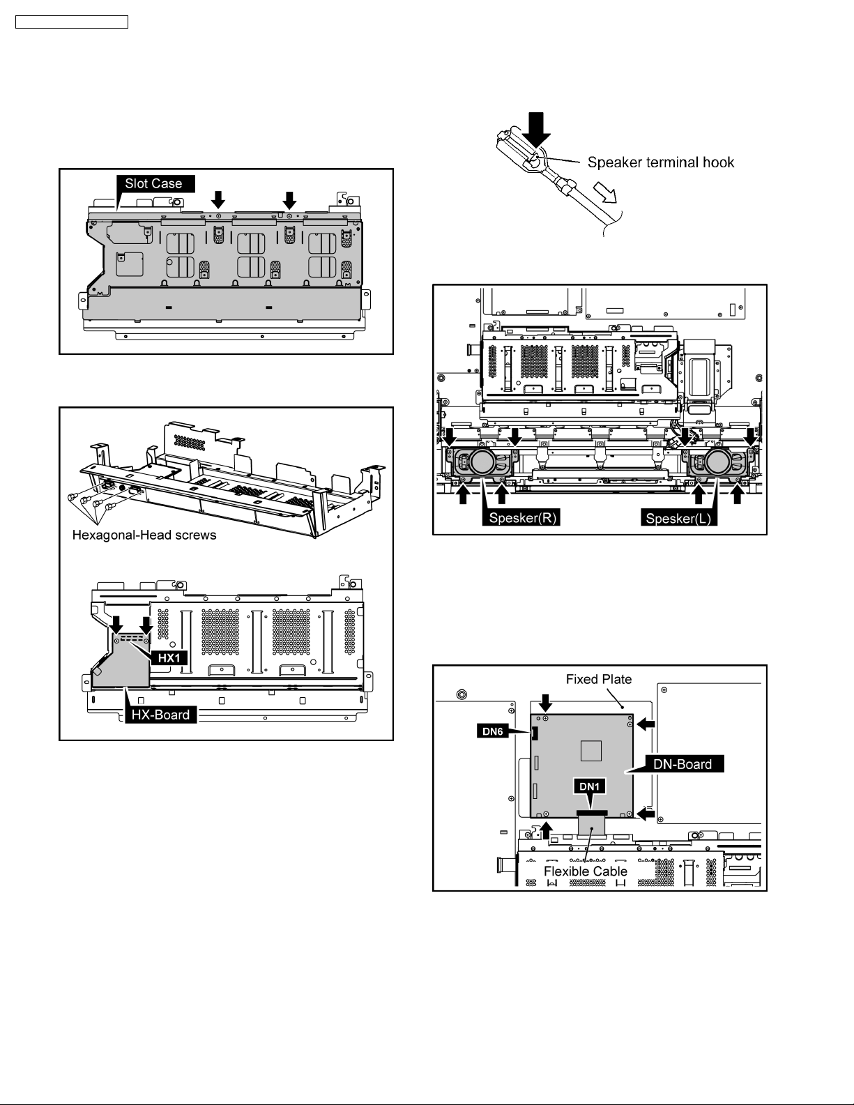
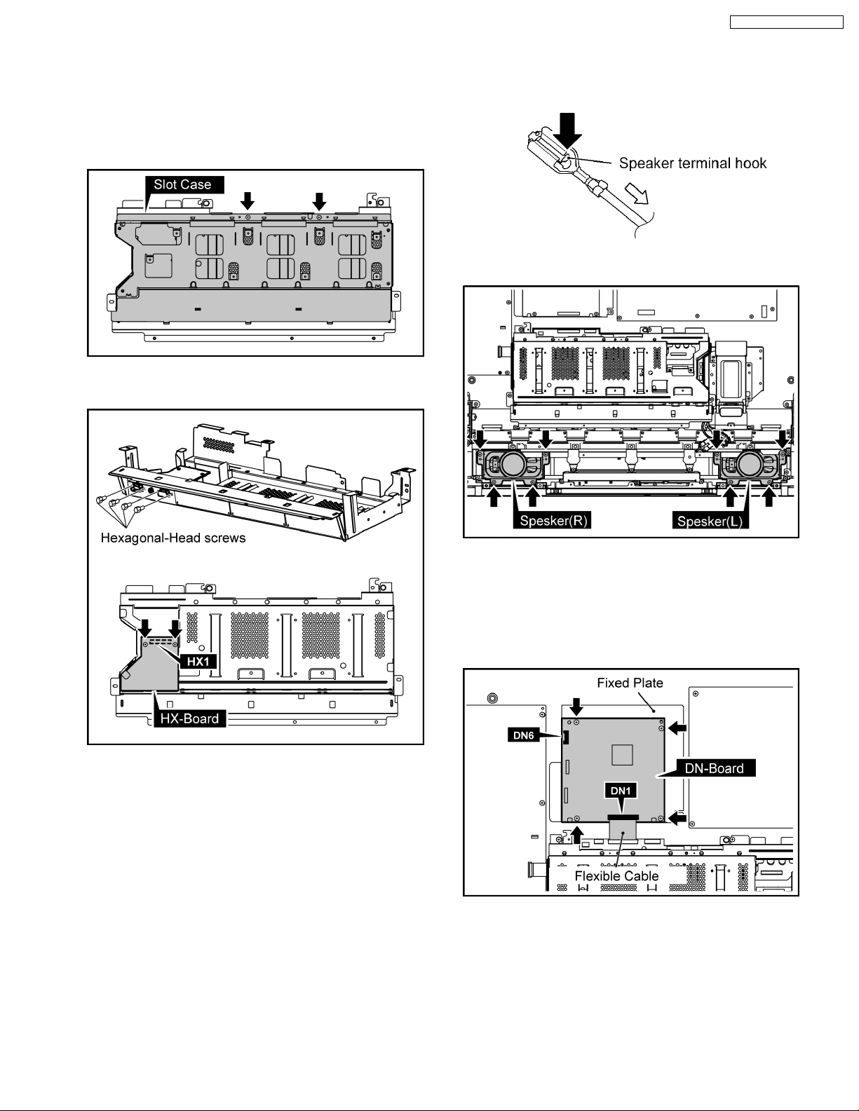
6.4. Removal of HX-Board
6.5. Removal of Speaker(L, R)
1. Remove the Slot Block.
(Refer to Removal of Slot Block)
2. Remove DS-Board.
(Refer to Removal of DS-Board)
3. Remove 2 screws and then remove the Slot Case.
4. Remove 4 Hexagonal-Head screws and 2 screws and then
remove HX-Board.
1. Connected terminal hook is pushed, and the speaker lead
in 4 places is pulled out.
2. Remove 8 screws and then remove the Speaker(L, R).
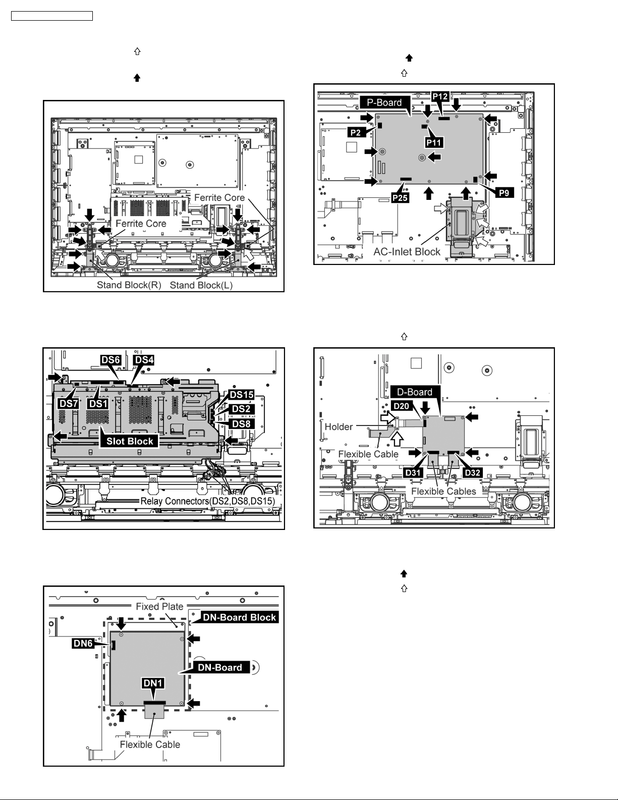
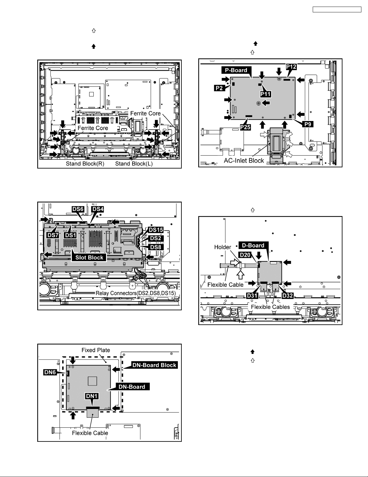
6.6. Removal of DN-Board
1. Disconnect the connector(DN6).
2. Remove the Flexible Cable from the connector(DN1).
3. Remove 4 screws and then remove DN-Board and the
Fixed Plate.
Note:
A re-setup of the destination is performed by MS mode
after DN-Board exchange.
10
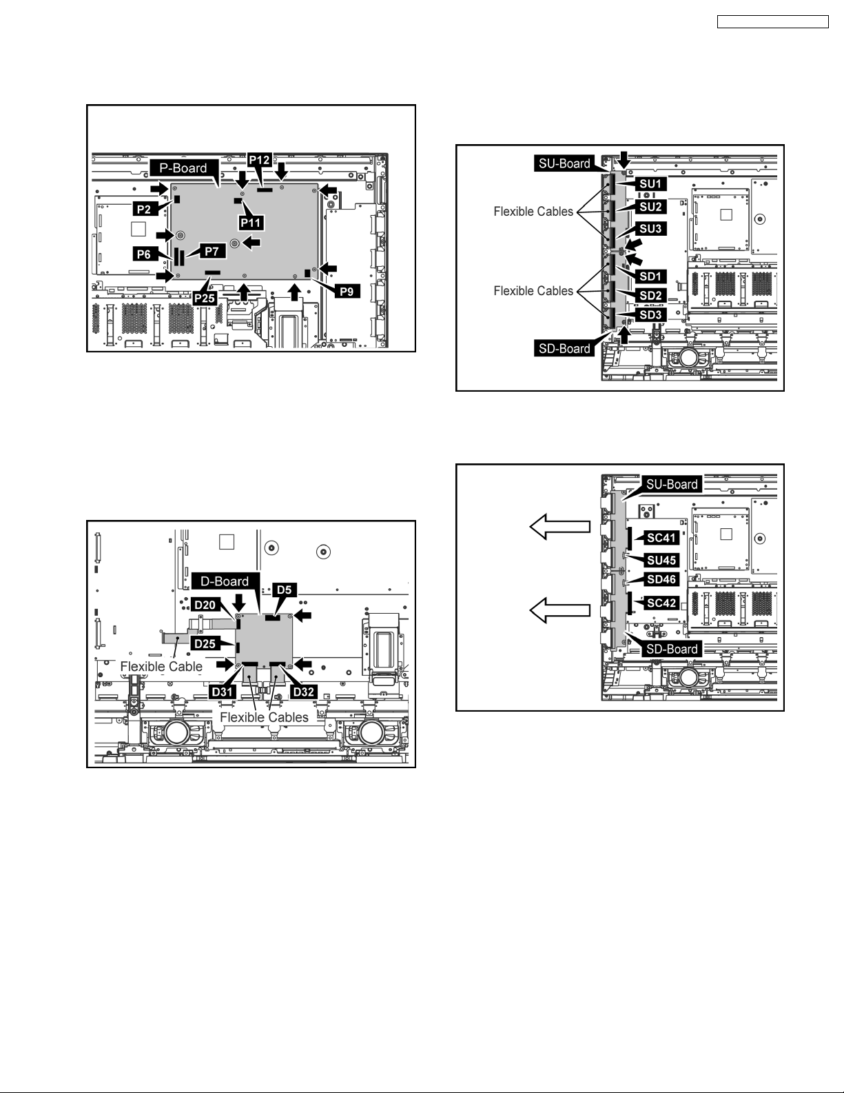
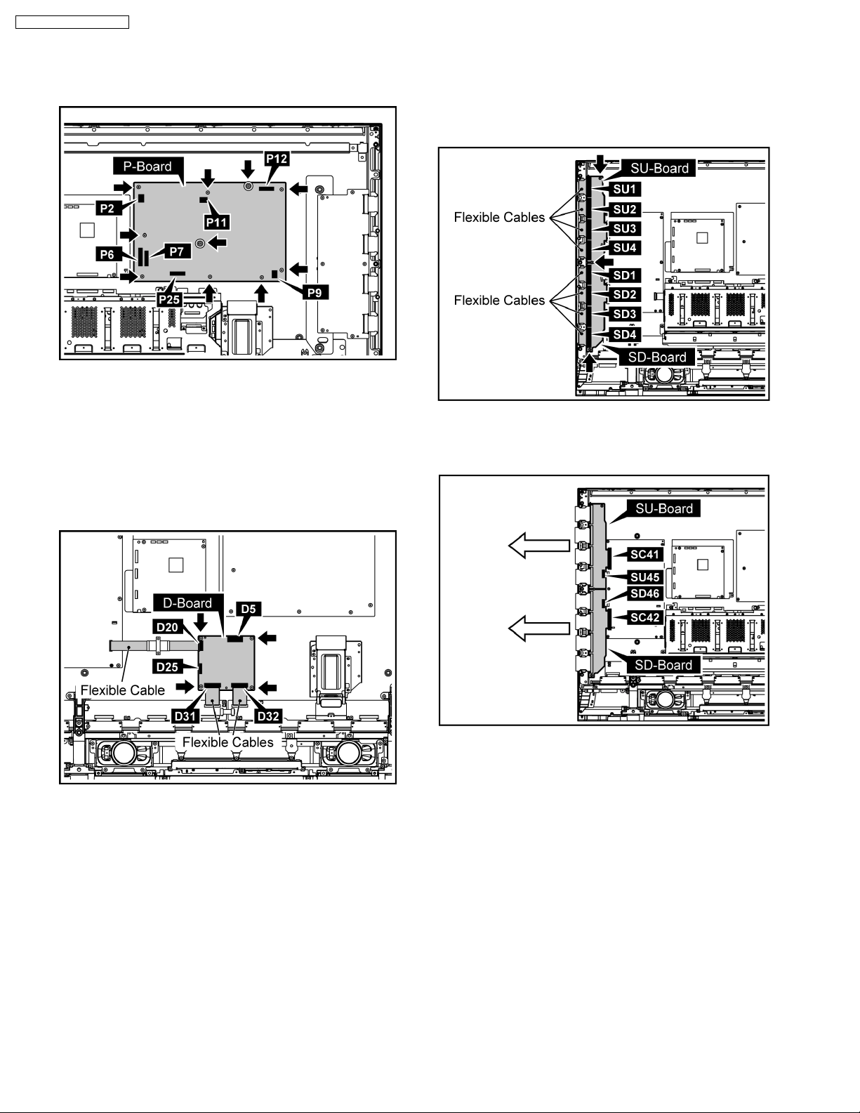
6.7. Removal of P-Board
1. Disconnect the connectors(P2, P6, P7, P9, P11, P12, P25)
2. Remove 10 screws and then remove P-Board.
6.8. Removal of D-Board
TH-37PR10U / TH-42PR10U
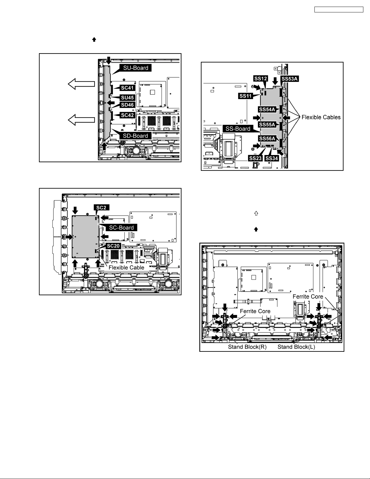
6.9. Removal of SU-Board and SDBoard
1. Remove the Flexible Cables from the connectors(SU1,
SU2, SU3, SD1, SD2, SD3).
2. Remove 4 screws.
1. Remove the Slot Block.
(Refer to Removal of Slot Block)
2. Disconnect the connectors(D5, D25)
3. Remove the Flexible Cables from the connectors (D20,
D31, D32).
4. Remove 4 screws and then remove D-Board.
3. Disconnect the connectors(SU45, SD46).
4. Slide SU-Board and SD-Board to the left, remove SU-Board
and SD-Board from the connectors(SC41, SC42).
11
TH-37PR10U / TH-42PR10U
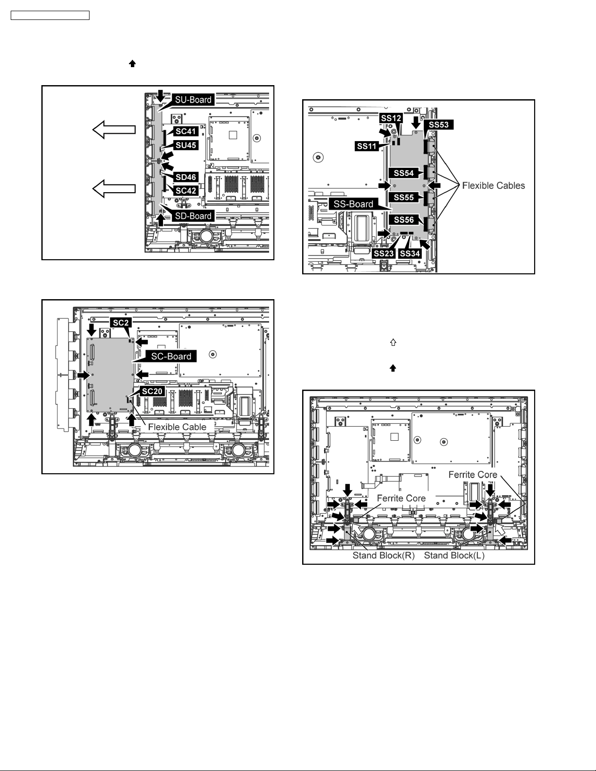
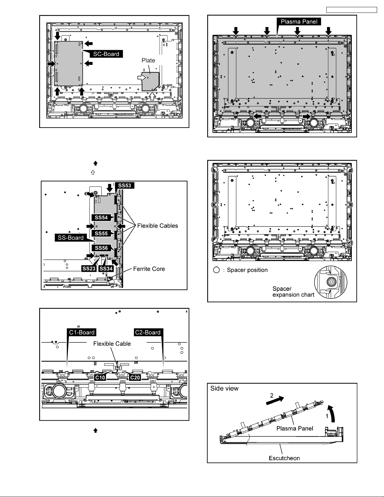
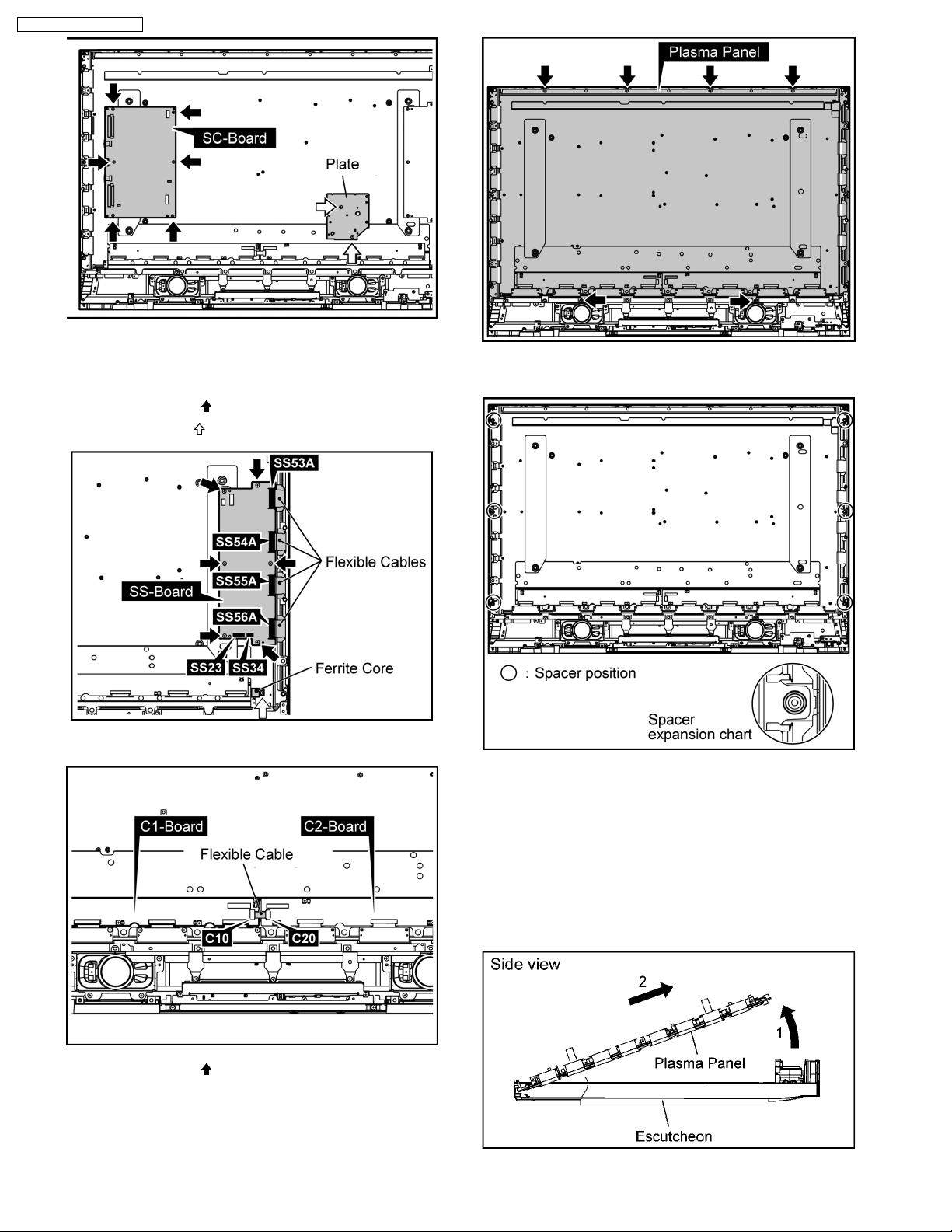
6.10. Removal of SC-Board
6.11. Removal of SS-Board
1. Disconnect the connectors (SU45, SD46).
2. Remove 4 screws (
Board to the left.
3. Disconnect the connectors(SC2, SC20).
4. Remove 6 screws and then remove SC-Board.
) and then slide SU-Board and SD-
1. Disconnect the connectors (SS11, SS12, SS23, SS34).
2. Remove the Flexible Cables from the connectors(SS53,
SS54, SS55, SS56)
3. Remove 6 screws and then remove SS-Board.
6.12. Removal of C1, C2-Board
1. Remove the Slot Block.
(Refer to Removal of Slot Block)
2. Remove 2 screws (
from the Stand Block(L, R).
3. Remove 12 screws (
R).
) and then remove the Ferrite Core
) and then remove the Stand Block(L,
12
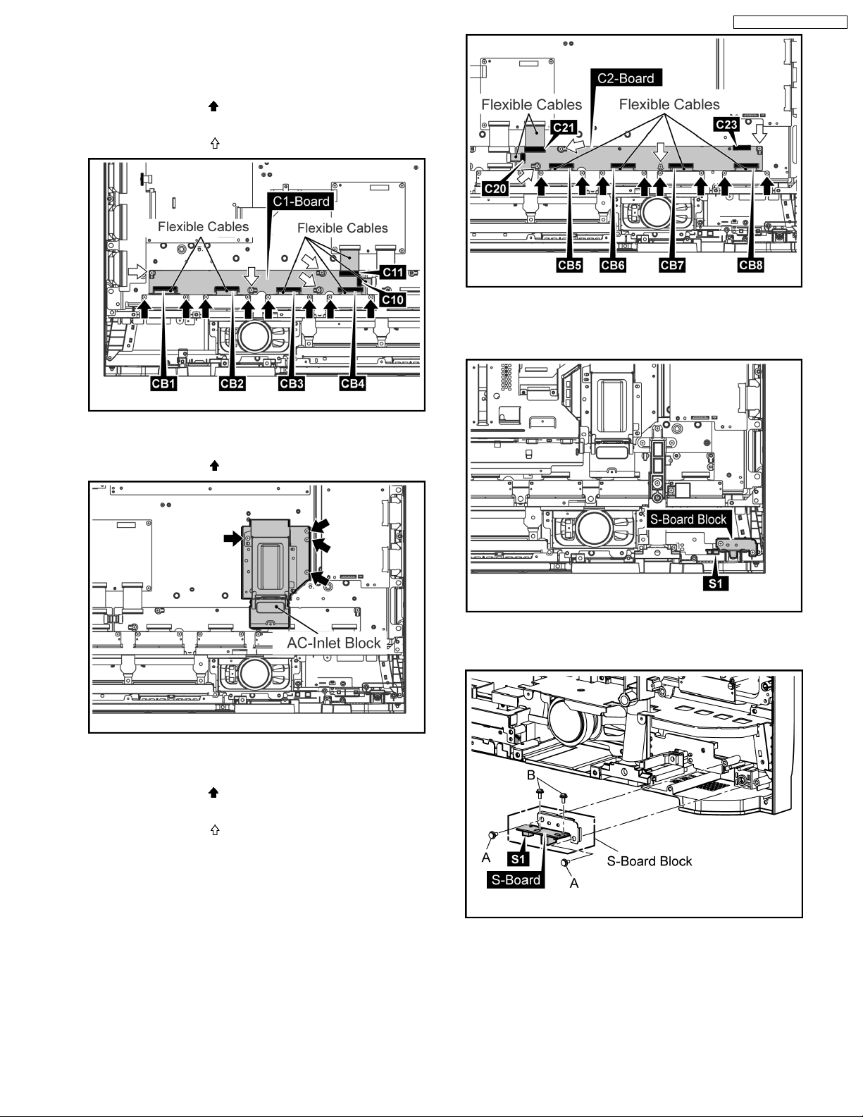
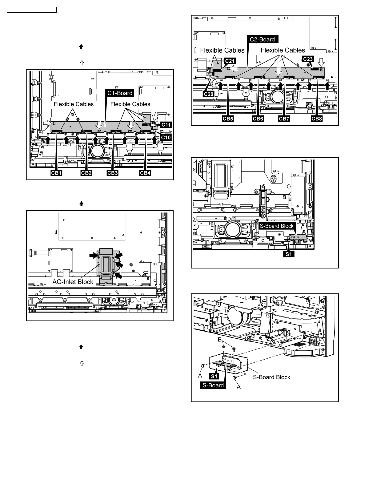
6.12.1. Removal of C1-Board
1. Remove the Flexible Cables from the connectors(C10,
C11).
2. Remove 8 screws (
from the connectors(CB1, CB2, CB3, CB4).
3. Remove 4 screws (
) and then remove the Flexible Cables
) and then remove C1-Board.
TH-37PR10U / TH-42PR10U
6.13. Removal of S-Board
1. Disconnect the connector(S1).
6.12.2. Removal of C2-Board
1. Remove 4 screws ( ) and then remove the AC-Inlet Block.
2. Remove the Flexible Cables from the connectors(C20 ,
C21, C23).
3. Remove 8 screws (
from the connectors(CB5, CB6, CB7, CB8).
4. Remove 4 screws (
) and then remove the Flexible Cables
) and then remove C2-Board.
2. Remove 2 screws(A) and then remove S-Board Block.
3. Remove 2 screws(B) and then remove S-Board.
13
TH-37PR10U / TH-42PR10U
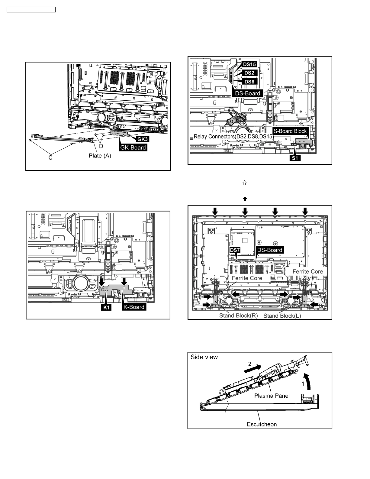
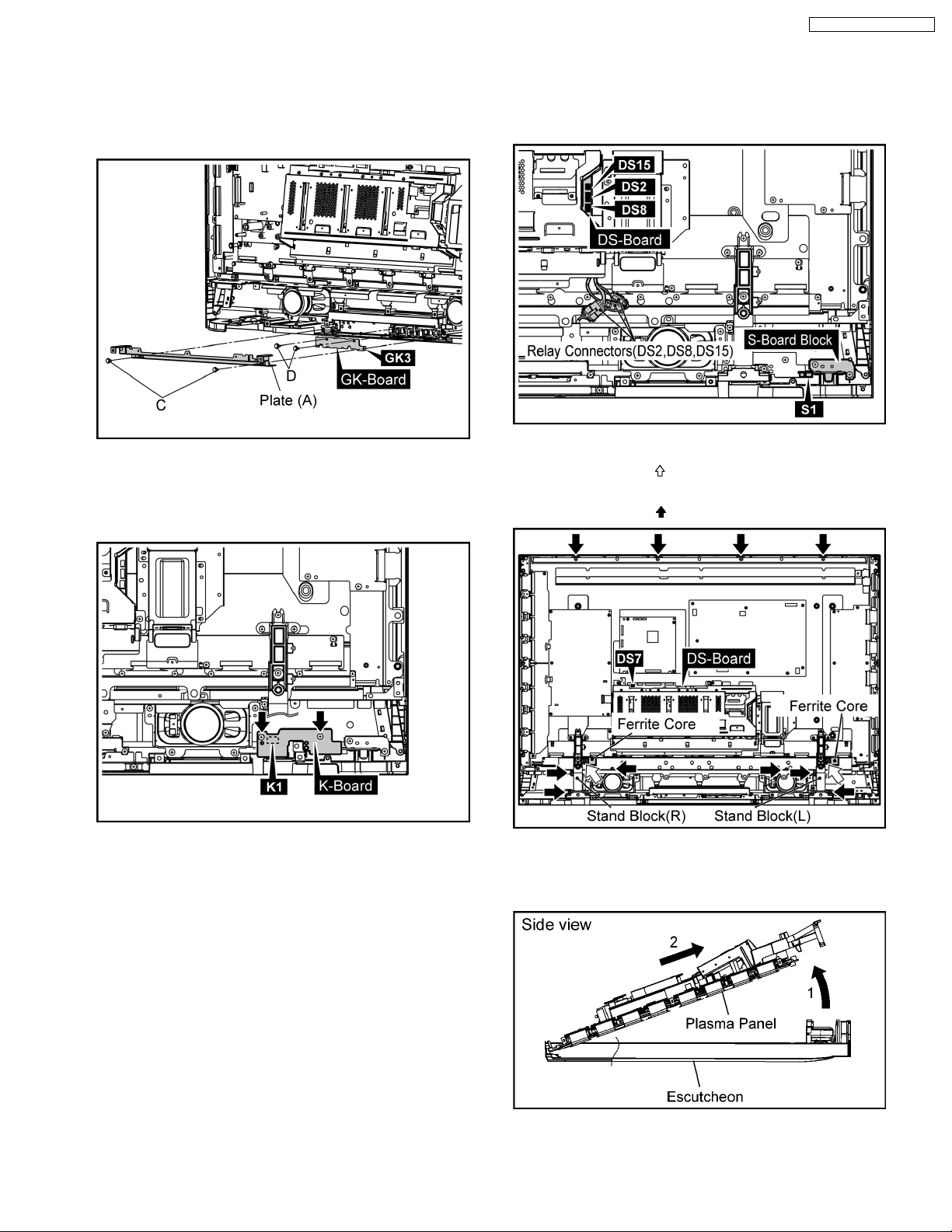
6.14. Removal of GK-Board
1. Remove 2 screws(C) and then remove the Plate(A).
2. Remove 2 screws(D).
3. Disconnect the connector(GK3) and then remove GKBoard.
6.15. Removal of K-Board
1. Remove 2 screws.
2. Then remove K-Board and disconnect the connector(K1).
6.16. Removal of Escutcheon and
the Front Glass
1. Disconnect the Relay connectors (DS2, DS8, DS15).
2. Disconnect the connector(S1).
3. Disconnect the connector(DS7).
4. Remove 2 screws (
from the Stand Block(L, R).
5. Remove 10 screws (
) and then remove the Ferrite core
).
6. Lift up the bottom of Plasma Panel to the arrow1 direction.
7. Pull the Plasma Panel to the arrow2 direction and then
remove the Plasma Panel.
14
8. Remove the S-Board Block.
(Refer to Removal of S-Board)
9. Remove K-Board.
(Refer to Removal of K-Board)
10. Remove GK-Board.
(Refer to Removal of GK-Board)
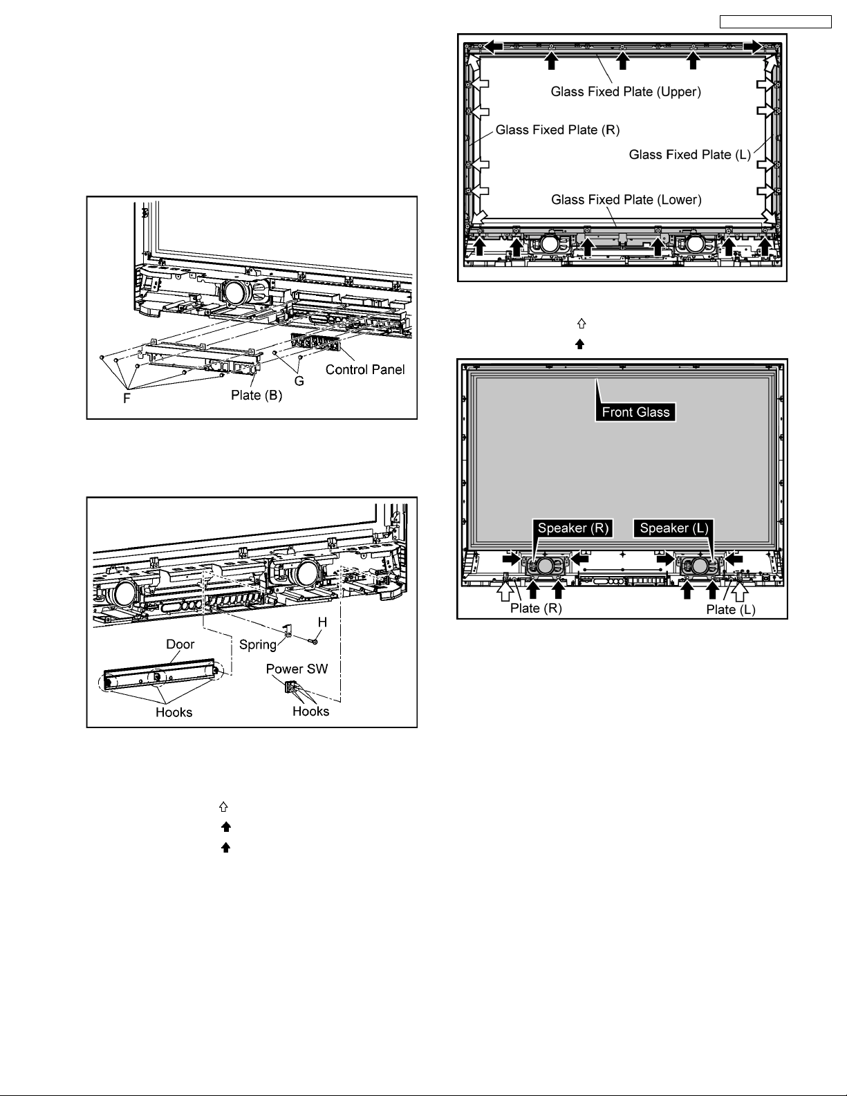
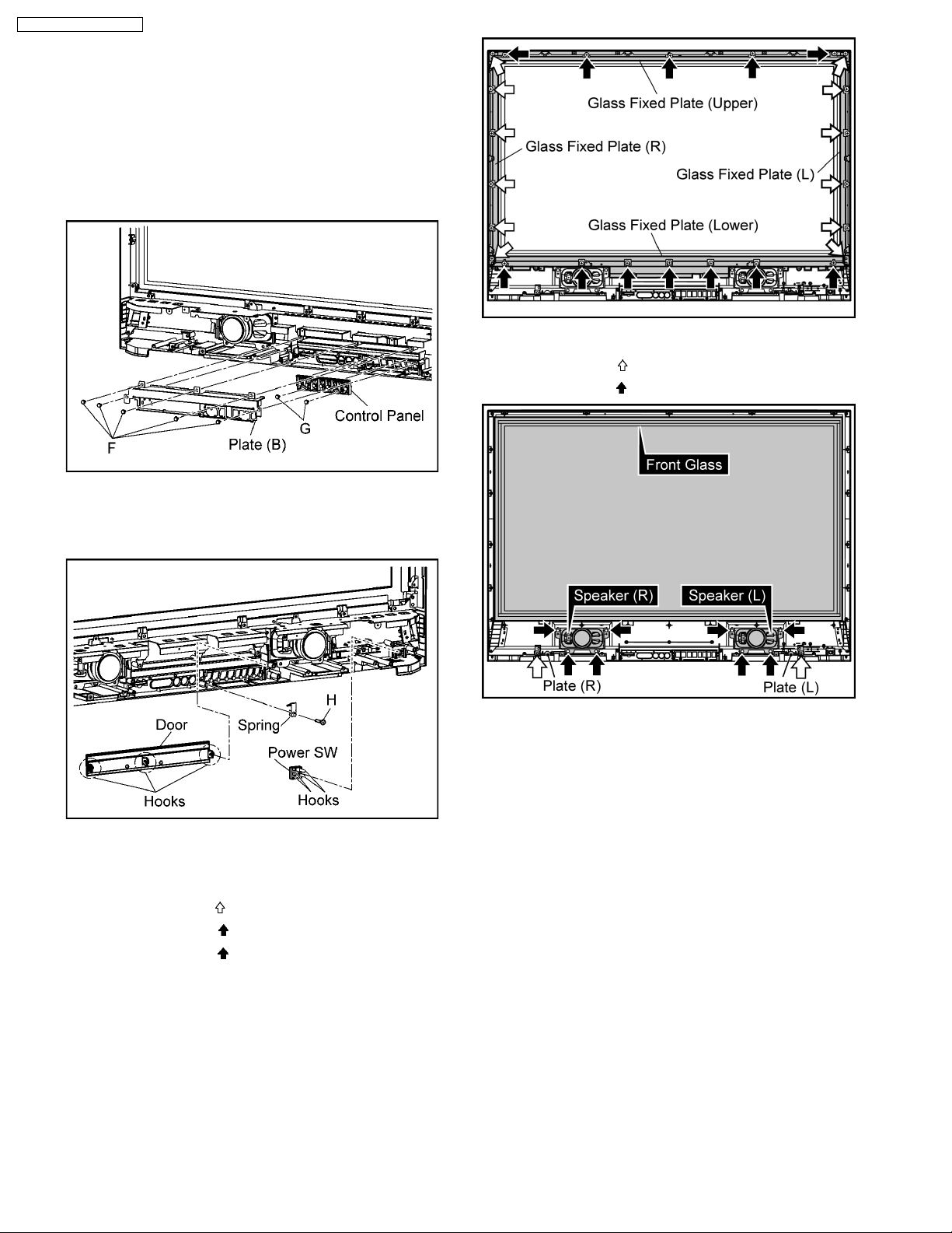
11. Remove 5 screws(F) and then remove the Plate(B).
12. Remove 2 screws(G) and then remove the Control Panel.
17. Remove the Front Glass.
18. Remove 2 screws (
19. Remove 8 screws (
) and then remove the Plate(L, R).
) and then remove the Speaker (L, R).
TH-37PR10U / TH-42PR10U
13. Remove 1 screw(H) and then remove the Spring.
14. Remove 3 hooks and then remove the Door.
15. Remove 4 hooks and then remove the Power SW.
16. Remove screws and then remove the Glass Fixed Plate (L,
R, Upper, Lower).
Removed number of screws:
12 screws (L, R) (
5 screws (Upper) (
6 screws (Lower) (
)
)
)
15
TH-37PR10U / TH-42PR10U
6.17. Removal of Plasma Panel
1. Remove 2 screws ( ) and then remove the Ferrite Core
from the Stand Block(L, R).
2. Remove 12 screws (
R).
3. Disconnect the connectors(DS1, DS4, DS6, DS7).
4. Remove 4 screws and then remove the Slot Block.
5. Disconnect the connectors(DS2, DS8, DS15).
) and then remove the Stand Block(L,
9. Disconnect the connectors(P2, P9, P11, P12, P25).
10. Remove 10 screws (
11. Remove 4 screws (
12. Disconnect the connector(D20).
13. Remove the Flexible Cables from the connectors(D31,
D32).
14. Remove 4 screws and then remove D-Board.
15. Remove 2 screws (
) and then remove P-Board.
) and then remove the AC-Inlet Block.
) and then remove the Holder.
6. Disconnect the connector(DN6).
7. Remove the Flexible Cable from the connector(DN1).
8. Remove 4 screws and then remove the DN-Board Block.
16. Remove SU-Board and SD-Board.
(Refer to Removal of SU-Board and SD-Board)
17. Remove 6 screws (
18. Remove 2 screws (
16
) and then remove SC-Board.
) and then remove the Plate.
19. Disconnect the connectors(SS23, SS34).
20. Remove the Flexible Cables from the connectors(SS53,
SS54, SS55, SS56).
21. Remove 6 screws (
22. Remove 1 screw (
) and then remove SS-Board.
) and then remove the Ferrite Core.
TH-37PR10U / TH-42PR10U
25. Remove the 6 Spacers and Spacer Rings from the Plasma
Panel.
23. Remove the Flexible Cable from the connectors(C10, C20).
24. Remove 6 screws ( ).
Caution:
· Please confirm the installation place of Spacer and
Spacer Ring when you exchange the Plasma Panel,
and install Spacer and Spacer Ring in an original
installation place after exchanging the Plasma
Panel.
26. Lift up the bottom of Plasma Panel to the arrow1 direction.
27. Pull the Plasma Panel to the arrow2 direction and then
remove the Plasma Panel.
17
TH-37PR10U / TH-42PR10U
7 Disassembly TH-42PR10U
· To disassemble P.C.B., wait for 1 minute after power was
off for discharge from electrolysis capacitors.
and marks indicate screw positions.
·
7.1. Removal of Rear Cover
1. Remove screws (×6 ,×6 , ×14 ,×8 ) and then
remove the Rear Cover.
7.3. Removal of DS-Board
1. Remove the Slot Block.
(Refer to Removal of Slot Block)
2. Disconnect the connector(DS14).
3. The Slot Block is turned inside out.
4. Remove 6 screws and then remove the Slot Cover.
7.2. Removal of Slot Block
1. Disconnect the connectors (DS1, DS4, DS6, DS7).
2. Remove 4 screws and then remove the Slot Block.
3. Disconnect the connectors(DS2, DS8, DS15).
5. Remove 6 screws and then remove DS-Board.
18
7.4. Removal of HX-Board
TH-37PR10U / TH-42PR10U
7.5. Removal of Speaker(L, R)
1. Remove the Slot Block.
(Refer to Removal of Slot Block)
2. Remove DS-Board.
(Refer to Removal of DS-Board)
3. Remove 2 screws and then remove the Slot Case.
4. Remove 4 Hexagonal-Head screws and 2 screws and then
remove HX-Board.
1. Connected terminal hook is pushed, and the speaker lead
in 4 places is pulled out.
2. Remove 8 screws and then remove the Speaker(L, R).
7.6. Removal of DN-Board
1. Disconnect the connector(DN6).
2. Remove the Flexible Cable from the connector(DN1).
3. Remove 4 screws and then remove DN-Board and the
Fixed Plate.
Note:
A re-setup of the destination is performed by MS mode
after DN-Board exchange.
19
TH-37PR10U / TH-42PR10U
7.7. Removal of P-Board
1. Disconnect the connectors(P2, P6, P7, P9, P11, P12, P25)
2. Remove 10 screws and then remove P-Board.
7.8. Removal of D-Board
7.9. Removal of SU-Board and SDBoard
1. Remove the Flexible Cables from the connectors(SU1,
SU2, SU3, SU4, SD1, SD2, SD3, SD4).
2. Remove 3 screws.
1. Remove the Slot Block.
(Refer to Removal of Slot Block)
2. Disconnect the connectors(D5, D25)
3. Remove the Flexible Cables from the connectors (D20,
D31, D32).
4. Remove 4 screws and then remove D-Board.
3. Disconnect the connectors(SU45, SD46).
4. Slide SU-Board and SD-Board to the left, remove SU-Board
and SD-Board from the connectors(SC41, SC42).
20
7.10. Removal of SC-Board
TH-37PR10U / TH-42PR10U
7.11. Removal of SS-Board
1. Disconnect the connectors(SU45, SD46).
2. Remove 3 screws (
Board to the left.
3. Disconnect the connectors(SC2, SC20).
4. Remove 6 screws and then remove SC-Board.
) and then slide SU-Board and SD-
1. Disconnect the connectors(SS11, SS12, SS23, SS34).
2. Remove the Flexible Cables from the connectors(SS53A,
SS54A, SS55A, SS56A)
3. Remove 6 screws and then remove SS-Board.
7.12. Removal of C1, C2-Board
1. Remove the Slot Block.
(Refer to Removal of Slot Block)
2. Remove 2 screws (
from the Stand Block(L, R).
3. Remove 12 screws (
R).
) and then remove the Ferrite Core
) and then remove the Stand Block(L,
21
TH-37PR10U / TH-42PR10U
7.12.1. Removal of C1-Board
1. Remove the Flexible Cables from the connectors(C10,
C11).
2. Remove 8 screws (
from the connectors(CB1, CB2, CB3, CB4).
3. Remove 4 screws (
) and then remove the Flexible Cables
) and then remove C1-Board.
7.13. Removal of S-Board
1. Disconnect the connector(S1).
7.12.2. Removal of C2-Board
1. Remove 4 screws ( ) and then remove the AC-Inlet Block.
2. Remove the Flexible Cables from the connectors(C20 ,
C21, C23).
3. Remove 8 screws (
from the connectors(CB5, CB6, CB7, CB8).
4. Remove 4 screws (
) and then remove the Flexible Cables
) and then remove C2-Board.
2. Remove 2 screws(A) and then remove S-Board Block.
3. Remove 2 screws(B) and then remove S-Board.
22
7.14. Removal of GK-Board
1. Remove 2 screws(C) and then remove the Plate(A).
2. Remove 2 screws(D).
3. Disconnect the connector(GK3) and then remove GKBoard.
7.15. Removal of K-Board
1. Remove 2 screws.
2. Then remove K-Board and disconnect the connector(K1).
TH-37PR10U / TH-42PR10U
7.16. Removal of Escutcheon and
the Front Glass
1. Disconnect the Relay connectors (DS2, DS8, DS15).
2. Disconnect the connector(S1).
3. Disconnect the connector(DS7).
4. Remove 2 screws (
from the Stand Block(L, R).
5. Remove 10 screws (
) and then remove the Ferrite core
).
6. Lift up the bottom of Plasma Panel to the arrow1 direction.
7. Pull the Plasma Panel to the arrow2 direction and then
remove the Plasma Panel.
23
TH-37PR10U / TH-42PR10U
8. Remove the S-Board Block.
(Refer to Removal of S-Board)
9. Remove K-Board.
(Refer to Removal of K-Board)
10. Remove GK-Board.
(Refer to Removal of GK-Board)
11. Remove 5 screws(F) and then remove the Plate(B).
12. Remove 2 screws(G) and then remove the Control Panel.
17. Remove the Front Glass.
18. Remove 2 screws (
19. Remove 8 screws (
) and then remove the Plate(L, R).
) and then remove the Speaker (L, R).
13. Remove 1 screw(H) and then remove the Spring.
14. Remove 3 hooks and then remove the Door.
15. Remove 4 hooks and then remove the Power SW.
16. Remove screws and then remove the Glass Fixed Plate (L,
R, Upper, Lower).
Removed number of screws:
12 screws (L, R) (
5 screws (Upper) (
7 screws (Lower) (
)
)
)
24
7.17. Removal of Plasma Panel
TH-37PR10U / TH-42PR10U
1. Remove 2 screws ( ) and then remove the Ferrite Core
from the Stand Block(L, R).
2. Remove 12 screws (
R).
3. Disconnect the connectors(DS1, DS4, DS6, DS7).
4. Remove 4 screws and then remove the Slot Block.
5. Disconnect the connectors(DS2, DS8, DS15).
) and then remove the Stand Block(L,
9. Disconnect the connectors(P2, P9, P11, P12, P25).
10. Remove 10 screws (
11. Remove 4 screws (
12. Disconnect the connector(D20).
13. Remove the Flexible Cables from the connectors(D31,
D32).
14. Remove 4 screws and then remove D-Board.
15. Remove 2 screws (
) and then remove P-Board.
) and then remove the AC-Inlet Block.
) and then remove the Holder.
6. Disconnect the connector(DN6).
7. Remove the Flexible Cable from the connector(DN1).
8. Remove 4 screws and then remove the DN-Board Block.
16. Remove SU-Board and SD-Board.
(Refer to Removal of SU-Board and SD-Board)
17. Remove 6 screws (
18. Remove 2 screws (
25
) and then remove SC-Board.
) and then remove the Plate.
TH-37PR10U / TH-42PR10U
19. Disconnect the connectors(SS23, SS34).
20. Remove the Flexible Cables from the connectors(SS53A,
SS54A, SS55A, SS56A).
21. Remove 6 screws (
22. Remove 1 screw (
) and then remove SS-Board.
) and then remove the Ferrite Core.
25. Remove the 6 Spacers and Spacer Rings from the Plasma
Panel.
23. Remove the Flexible Cable from the connectors(C10, C20).
24. Remove 6 screws ( ).
Caution:
· Please confirm the installation place of Spacer and
Spacer Ring when you exchange the Plasma Panel,
and install Spacer and Spacer Ring in an original
installation place after exchanging the Plasma
Panel.
26. Lift up the bottom of Plasma Panel to the arrow1 direction.
27. Pull the Plasma Panel to the arrow2 direction and then
remove the Plasma Panel.
26
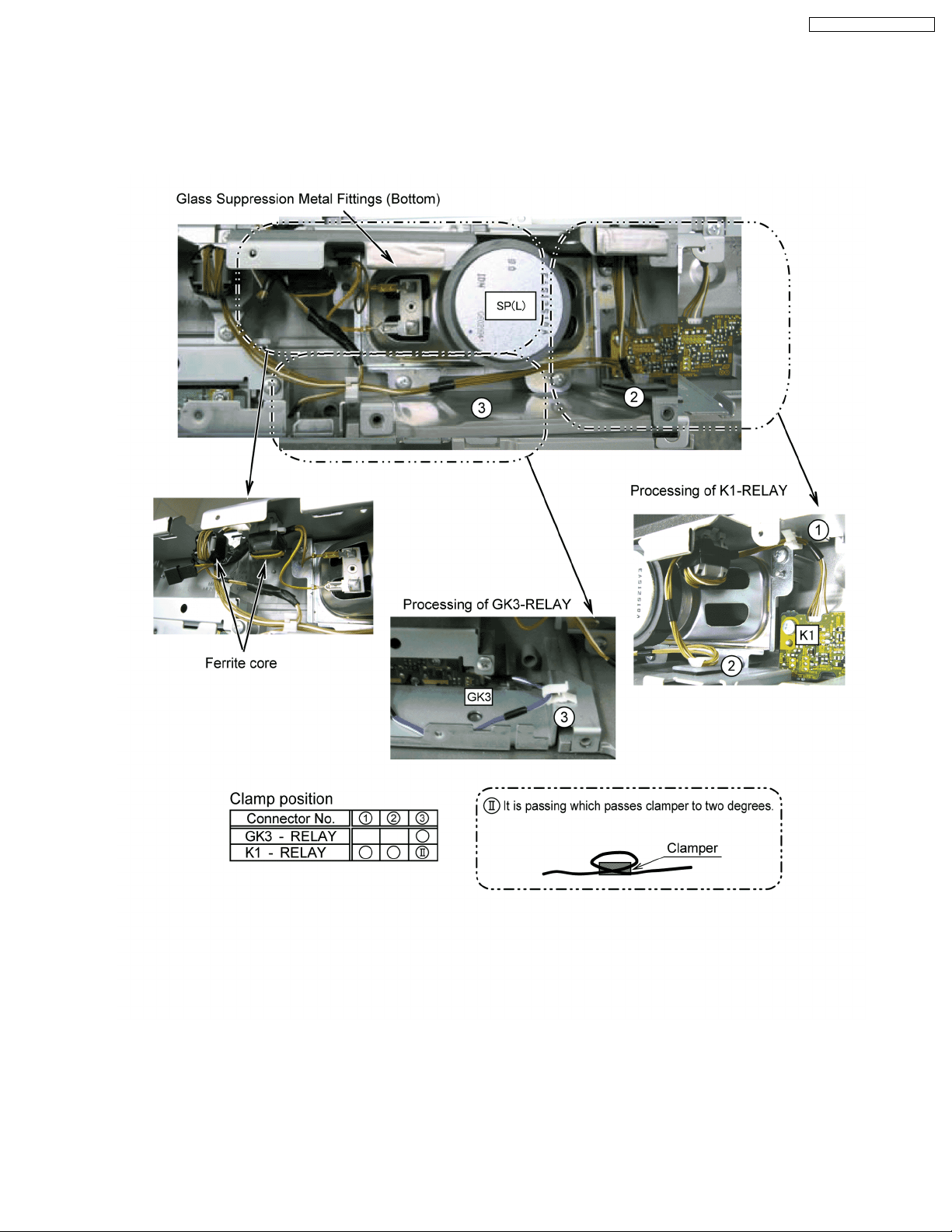
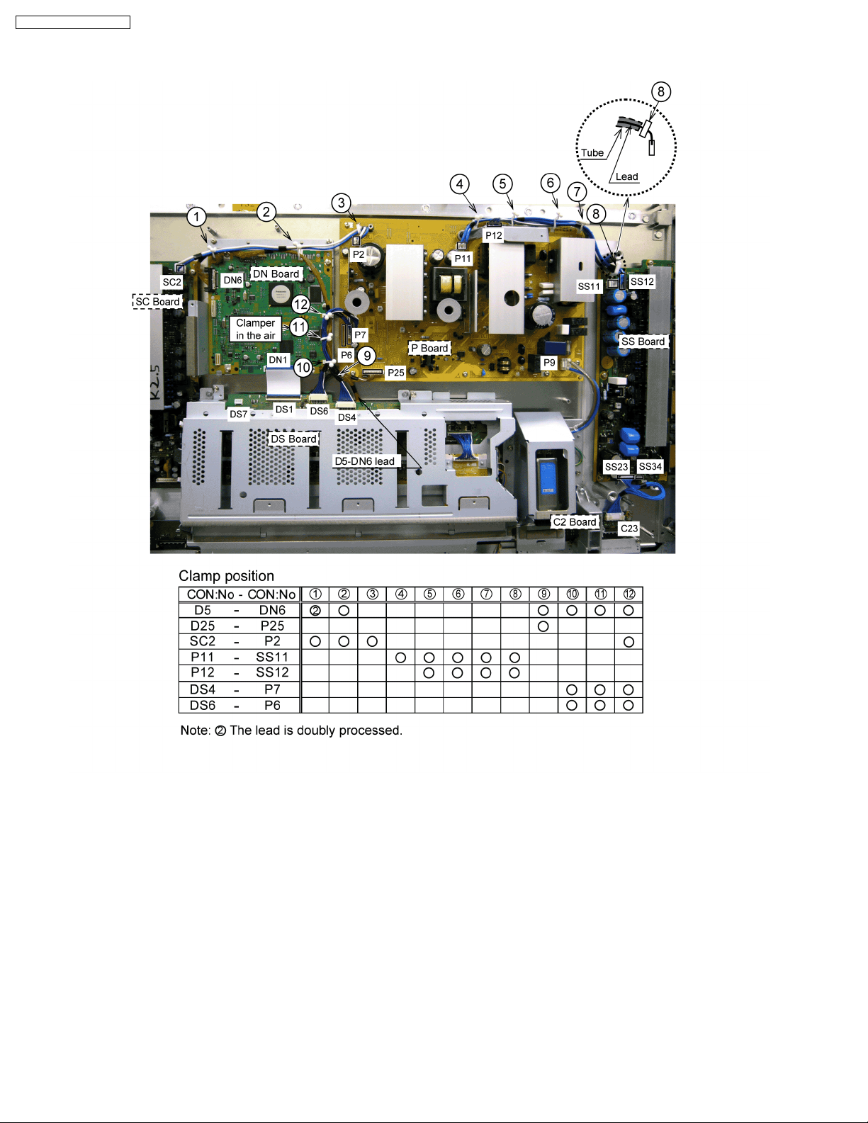
8 Location of Lead Wiring
8.1. Wiring for the 37 inch model
8.1.1. Lead Wiring (1)
The lead wiring is dressed as shown in figure.
TH-37PR10U / TH-42PR10U
27
TH-37PR10U / TH-42PR10U
8.1.2. Lead wiring (2)
The lead wiring is dressed as shown in figure.
28
8.1.3. Lead wiring (3)
The lead wiring is dressed as shown in figure.
TH-37PR10U / TH-42PR10U
29

TH-37PR10U / TH-42PR10U
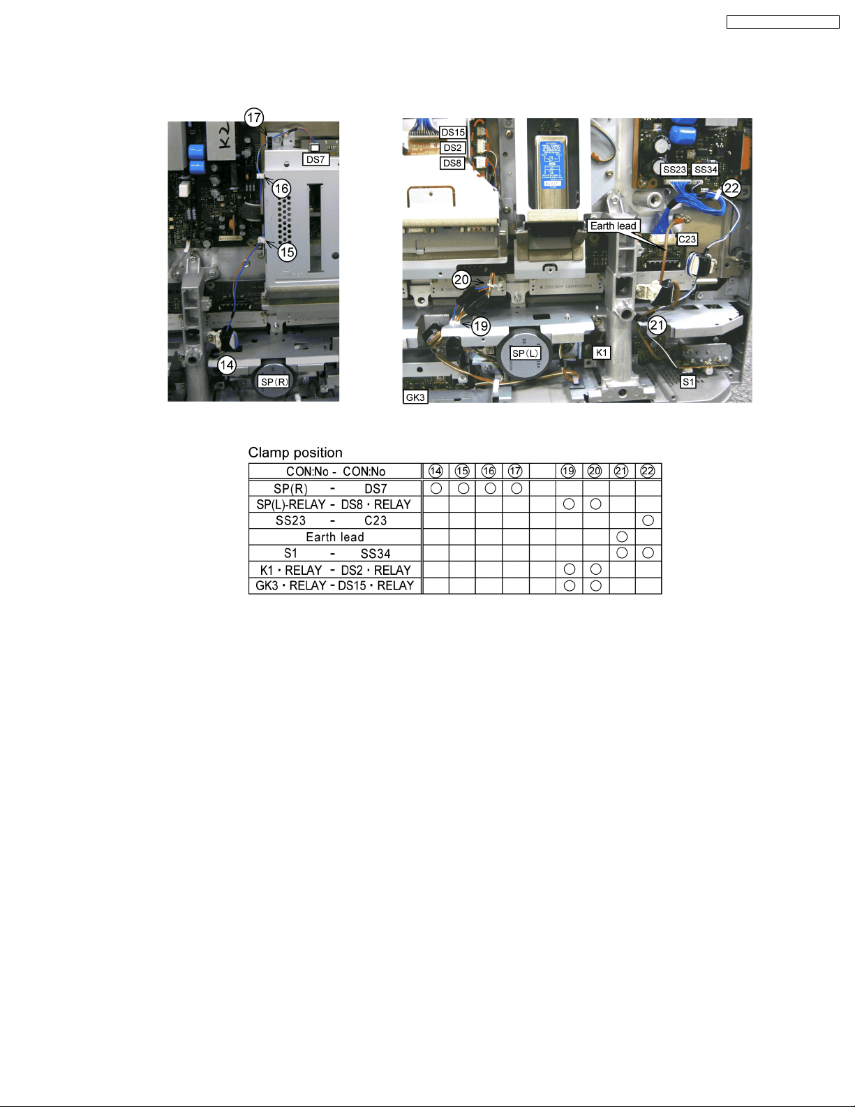
8.2. Wiring for the 42 inch model
8.2.1. Lead Wiring (1)
The lead wiring is dressed as shown in figure.
30