

Page 1

1
2 3
4
5 6
7
8 9
0
Operating Instructions
Progressive Plasma Television
Model No.
TH-37PA20
TH-42PA20
Pedestal stand shown above is optional extra.
Please read these instructions before operating your set and retain them for future reference.
English
TQBC0696-1
Page 2

Dear Panasonic Customer
Welcome to the Panasonic family of customers. We hope that you will have many years of
enjoyment from your new Plasma TV.
To obtain maximum benefit from your set, please read these Instructions before
making any adjustments, and retain them for future reference.
Retain your purchase receipt also, and note down the model number and serial
number of your set in the space provided on the rear cover of these instructions.
2
Page 3

Table of Contents
Important Safety Notice ............................................ 4
Safety Precautions .................................................... 5
Supplied Accessories ............................................... 7
Fitting remote control batteries ................................ 7
Battery cautions ....................................................... 7
Cable Connection...................................................... 8
Antenna Connection ................................................ 9
AV & COMPONENT Connection ............................ 10
Headphones / AV3 terminals Connection ............... 11
PC Input terminals Connection .............................. 12
Power ON / OFF ....................................................... 13
AC cord Connection ............................................... 13
Power On/Off ......................................................... 13
General Operation ................................................... 14
Front panel controls and Remote control ............... 14
Using the On Screen Displays ............................... 16
Tuning Channels ..................................................... 18
Auto tuning ............................................................. 18
Auto tuning (via front panel) ................................... 18
Manual tuning ........................................................ 19
Manual tuning (via front panel) .............................. 19
Fine tuning ............................................................. 20
How to Cancel the Fine tuning ............................... 20
Programme Number Skip ...................................... 21
How to Cancel the Skip Function.......................... 21
Channel Allocation ................................................. 22
Owner ID .................................................................. 23
Setup Adjustment ................................................... 24
Teletext ................................................................... 24
Off timer ................................................................. 24
Ch colour set .......................................................... 24
Child lock ............................................................... 24
Power save ............................................................ 24
VCR/GAME ............................................................ 24
Colour system ........................................................ 24
Picture Adjustment ................................................. 25
Sound Adjustment .................................................. 27
Channel Search ....................................................... 28
Aspect Controls ...................................................... 29
PC mode Adjustments ............................................ 30
Advanced settings .................................................. 31
Adjusting Position and Size ................................... 32
Multi Screen ............................................................. 33
Multi PIP ................................................................. 33
Teletext ..................................................................... 34
Advanced Remote Control Operation ................... 37
Stereo Bilingual Sound Selection ........................... 37
VCR / DVD Control ................................................ 37
Manufacturer setting .............................................. 38
Troubleshooting ...................................................... 39
For your Guidance .................................................. 40
Input signal can be displayed ................................ 40
Specifications .......................................................... 41
3
Page 4
Important Safety Notice
WARNING
1) To prevent damage which may result in fire or shock hazard, do not expose this appliance to rain or
moisture.
Do not place containers with water (flower vase, cups, cosmetics, etc.) above the set. (including on
shelves above, etc.)
2) To prevent electric shock, do not remove cover. No user serviceable parts inside. Refer servicing to qualified
service personnel.
3) Do not remove the earthing pin on the power plug. This apparatus is equipped with a three pin earthing-type
power plug. This plug will only fit an earthing-type power outlet. This is a safety feature. If you are unable to
insert the plug into the outlet, contact an electrician.
Do not defeat the purpose of the earthing plug.
CAUTION
This appliance is intended for use in environments which are relatively free of electromagnetic fields.
Using this appliance near sources of strong electromagnetic fields or where electrical noise may overlap with the
input signals could cause the picture and sound to wobble or cause interference such as noise to appear.
To avoid the possibility of harm to this appliance, keep it away from sources of strong electromagnetic fields.
To prevent electric shock, ensure the grounding pin on the AC cord power plug is securely connected.
Trademark Credits
VGA is a trademark of International Business Machines Corporation.
•
Macintosh is a registered trademark of Apple Computer, USA.
•
S-VGA is a registered trademark of the Video Electronics Standard Association.
•
Even if no special notation has been made of company or product trademarks, these trademarks have been fully
respected.
CAUTION:
Symptom
After-images appear
Do not allow a still picture to be displayed for an extended period, as this can
cause a permanent after-image to remain on the Plasma TV.
Examples of still pictures include logos, video games, computer images, teletext
and images displayed in 4:3 mode.
Note:
The permanent after-image on the Plasma TV resulting from fixed image use is
not an operating defect and as such is not covered by the Warranty.
This product is not designed to display fixed images for extended periods of time.
Check
4
Page 5

Safety Precautions
WARNING
Setup
This Plasma TV is for use only with the following optional accessories. Use with any other type of optional
accessories may cause instability which could result in the possibility of injury.
(All of the following accessories are manufactured by Matsushita Electric Industrial Co., Ltd.)
Pedestal .............................................. TY-ST42PA20
•
Display stand ...................................... TY-S42PA20W (TH-42PA20), TY-S37PA20W (TH-37PA20)
•
Wall-hanging bracket (vertical) ........... TY-WK42PV2W
•
Always be sure to ask a qualified technician to carry out set-up.
Do not place the Plasma TV on sloped or unstable surfaces.
The Plasma TV may fall off or tip over.
•
Do not place any objects on top of the Plasma TV.
If water is spilt onto the Plasma TV or foreign objects get inside it, a short-circuit may occur which could result in
•
fire or electric shock. If any foreign objects get inside the Plasma TV, please consult your local Panasonic dealer.
If using the pedestal (optional accessory), leave a space of at least 10 cm at the top, left and right, at least 6
cm at the bottom, and at least 7 cm at the rear. If using some other setting-up method, leave a space of at
least 10 cm at the top, bottom, left and right, and at least 1.9 cm at the rear.
Avoid installing this product near electronic equipment that is easy to receive electromagnetic waves.
It will cause interference in image, sound, etc. In particular, keep video equipment away from this product.
•
When using the Plasma TV
The Plasma TV is designed to operate on 220 - 240 V AC, 50/60 Hz.
Do not cover the ventilation holes.
Doing so may cause the Plasma TV to overheat, which can cause fire or damage to the Plasma TV.
•
Do not stick any foreign objects into the Plasma TV.
Do not insert any metal or flammable objects into the ventilations holes or drop them onto the Plasma TV, as
•
doing so can cause fire or electric shock.
Do not remove the cover or modify it in any way.
High voltages which can cause severe electric shocks are present inside the Plasma TV. For any inspection,
•
adjustment and repair work, please contact your local Panasonic dealer.
Securely insert the power cord plug as far as it will go.
If the plug is not fully inserted, heat may be generated which could cause fire. If the plug is damaged or the wall
•
socket plate is loose, they shall not be used.
Do not handle the power cord plug with wet hands.
Doing so may cause electric shocks.
•
Do not do anything that may damage the power cable. When disconnecting the power cable, pull on the plug
body, not the cable.
Do not damage the cable, make any modifications to it, place heavy objects on top of it, heat it, place it near any
•
hot objects, twist it, bend it excessively or pull it. To do so may cause fire and electric shock. If the power cable
is damaged, have it repaired at your local Panasonic dealer.
If the Plasma TV is not going to be used for any prolonged length of time, unplug the power cord plug from
the wall outlet.
5
Page 6

Safety Precautions
If problems occur during use
If a problem occurs (such as no picture or no sound), or if smoke or an abnormal odour starts to come out
from the Plasma TV, immediately unplug the power cord plug from the wall outlet.
If you continue to use the Plasma TV in this condition, fire or electric shock could result. After checking that the
•
smoke has stopped, contact your local Panasonic dealer so that the necessary repairs can be made. Repairing
the Plasma TV yourself is extremely dangerous, and shall never be done.
If water or foreign objects get inside the Plasma TV, if the Plasma TV is dropped, or if the cabinet becomes
damages, disconnect the power cord plug immediately.
A short circuit may occur, which could cause fire. Contact your local Panasonic dealer for any repairs that need to
•
be made.
CAUTION
When using the Plasma TV
Do not bring your hands, face or objects close to the ventilation holes of the Plasma TV.
Heated air comes out from the ventilation holes at the top of Plasma TV will be hot. Do not bring your hands or
•
face, or objects which cannot withstand heat, close to this port, otherwise burns or deformation could result.
Be sure to disconnect all cables before moving the Plasma TV.
If the Plasma TV is moved while some of the cables are still connected, the cables may become damaged, and fire
•
or electric shock could result.
Disconnect the power cord plug from the wall socket as a safety precaution before carrying out any cleaning.
Electric shocks can result if this is not done.
•
Clean the power cable regularly to prevent it becoming dusty.
If dust built up on the power cord plug, the resultant humidity can damage the insulation, which could result in fire.
•
Pull the power cord plug out from the wall outlet and wipe the mains lead with a dry cloth.
This Plasma TV radiates infrared rays, therefore it may affect other infrared communication equipment.
Install your infrared sensor in a place away from direct or reflected light from your Plasma TV.
Cleaning and maintenance
The front of the display panel has been specially treated. Wipe the panel surface gently using only a cleaning
cloth or a soft, lint-free cloth.
If the surface is particularly dirty, wipe with a soft, lint-free cloth which has been soaked in pure water or water to
•
which a small amount of neutral detergent has been added, and then wipe it evenly with a dry cloth of the same
type until the surface is dry.
Do not scratch or hit the surface of the panel with fingernails or other hard objects, otherwise the surface may
•
become damaged. Furthermore, avoid contact with volatile substances such as insect sprays, solvents and thinner,
otherwise the quality of the surface may be adversely affected.
If the cabinet becomes dirty, wipe it with a soft, dry cloth.
If the cabinet is particularly dirty, soak the cloth in water to which a small amount of neutral detergent has been
•
added and then wring the cloth dry. Use this cloth to wipe the cabinet, and then wipe it dry with a dry cloth.
Do not allow any detergent to come into direct contact with the surface of the Plasma TV.
•
If water droplets get inside the unit, operating problems may result.
Avoid contact with volatile substances such as insect sprays, solvents and thinner, otherwise the quality of the
•
cabinet surface may be adversely affected or the coating may peel off. Furthermore, do not leave it for long
periods in contact with articles made from rubber or PVC.
6
Page 7

Supplied Accessories
Check the accessories before installations.
Operating Instruction book
•
Batteries for the Remote
•
Control Transmitter
(2 × R6 (UM3) size)
Remote Control Transmitter
•
(EUR511281)
Ferrite core
•
(small size) × 5
AC cord
•
1
2 3
4
5 6
7
8 9
0
Ferrite core
•
(large size) × 3
Installing the ferrite core (Small size)
1
Pull back the tabs
(in two places)
2
3
Open
Press the cable
through and close
Installing the ferrite core (Large size)
1
Pull back the tabs
(in two places)
2
3
Open
Press the cable
through and close
Fitting remote control batteries
123
Slide off the battery cover Insert batteries - note correct
Do not use rechargeable (Ni-Cd) batteries.
They are different in shape and performance and may fail to ensure correct operation.
Two “R6 (UM3)” size
Replace the cover
polarity (+ and -)
Battery cautions
The incorrect use of batteries can cause electrolyte leakage which will corrode the Remote Control or cause the
batteries to burst.
Observe the following precaution:
1. Batteries shall always be replaced as a pair. Always use new batteries when replacing the old set.
2. Do not combine a used battery with a new one.
3. Do not mix battery types (example:“Zinc Carbon” with “Alkaline”).
4. Do not attempt to charge, short-circuit, disassemble, heat or burn used batteries.
5. Battery replacement is necessary when remote control acts sporadically or stops operating the TV set.
7
Page 8
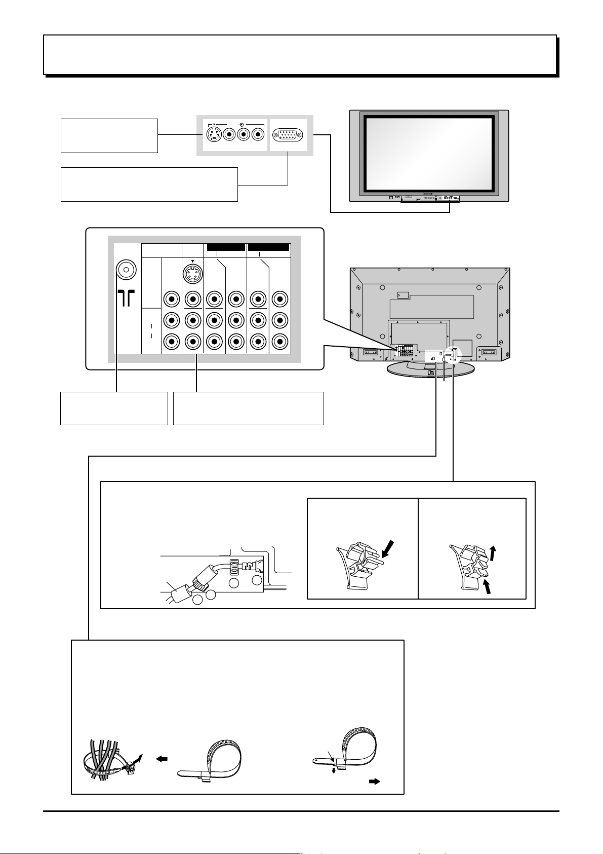
Cable Connection
Front AV terminals
(see page 11)
From EXTERNAL monitor terminal
on Computer (see page 12)
MONITOR
OUT
S VIDEO
VIDEO
L
AUDIO
R
ANTENNA IN terminal
(see page 9)
AV1
IN
MONO
AV & COMPONENT terminals
(see page 10)
AV 3
S VIDEO VIDEO
MONO MONO
L R
AV2 IN AV4 IN
COMPONENT COMPONENT
YY
P
B
P
R
PC
VIDEO
3
CHANNELVOLUMEACTIONINPUT
HPJ
PC
S-VIDEO
VIDEO
R AUDIO L
P
B
P
R
– AC cord fixing
1. Connect power plug to the socket of
the main body.
2. Fix the left clamper.
3. Fix the right clamper.
How to fix: Fix by
pushing in till a clicking
sound is heard.
4. Install the ferrite core.
Ferrite core
(large size)
(supplied)
2
4
1
3
– Cable fixing bands
Secure any excess cables with bands as required.
To secure cables connected to Terminals, wrap the cable fixing band
around them then pass the pointed end through the locking block, as
shown in the figure.
While ensuring there is sufficient slack in cables to minimize stress
(especially in the power cord), firmly bind all cables with the
supplied fixing band.
To tighten:
To loosen:
Push the catch
Pull
How to release: Pull
up while drawing the
knob.
8
Pull
Page 9
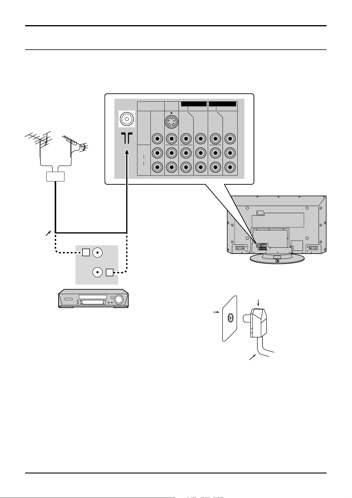
Cable Connection
Antenna Connection
For proper reception of VHF/UHF channels, an external antenna is required. For best reception, an outdoor antenna
is recommended.
VHF Aerial
Mixer
75 Ohm
Coaxial
Cable
UHF Aerial
OR
ANT INPUT
MONITOR
OUT
S VIDEO
VIDEO
L
AUDIO
R
AV1
IN
MONO
MONO MONO
AV2 IN AV4 IN
COMPONENT COMPONENT
YY
PB
PR
PB
PR
ANT OUTPUT
Coaxial aerial plug
VCR
RF in
Terminal
75 Ohm Coaxial Cable
Notes:
(1) To obtain optimum quality picture and sound, an Aerial, the correct cable (75 Ohm coaxial) and the correct terminating
plug are required.
(2) If a communal Aerial system is used, you may require the correct connection cable and plug between the wall
Aerial socket and your television receiver.
(3) Your local Television Service Centre or Dealer may be able to assist you in obtaining the correct Aerial system for
your particular area and the accessories required.
(4) Any matters regarding Aerial installation, upgrading of existing systems or accessories required, and the costs
incurred, are the responsibility of you, the Customer.
9
Page 10

Cable Connection
AV & COMPONENT Connection
How to connect the Monitor Output Terminals to other Equipment
VCR
MONITOR
VIDEO
IN
L
Amplifier to speaker
system
AUDIO
IN
R
Example of output
signal source
How to connect the AV1 Input Terminals
S VIDEO VCR
Connect the S-VIDEO or
VIDEO terminal
CAMCORDER
VCR
S VIDEO
OUT
VIDEO
OUT
R
AUDIO
OUT
L
Example of input
signal source
MONITOR
OUT
MONO
AV1 IN
MONITOR
OUT
S VIDEO
VIDEO
L
AUDIO
R
MONITOR
OUT
S VIDEO
VIDEO
L
AUDIO
R
AV2 IN AV4 IN
AV1
COMPONENT COMPONENT
IN
MONO
MONO MONO
AV2 IN AV4 IN
AV1
COMPONENT COMPONENT
IN
MONO
MONO MONO
YY
P
B
P
R
YY
P
B
P
R
P
B
P
R
P
B
P
R
How to connect the DVD Input Terminals
COMPONENT VIDEO OUT
P
R
P
DVD
Digital TV-SET-TOP-BOX
(DTV-STB)
Y, PB, PR,
OUT
VIDEO
OUT
AUDIO
OUT
Example of input
B
Y
Y
P
B
L
R
MONO
AV2 IN or
AV4 IN
P
R
MONITOR
OUT
S VIDEO
VIDEO
L
AUDIO
R
AV1
MONO
IN
signal source
Notes:
• Change the input signal to use the colour buttons on the remote control. (see page 17)
• Additional equipment, cables and adapter plugs shown are not supplied with this set.
• When a Monaural VCR is used, connect the Monaural Audio cable to the Audio “L”(Left) terminal.
10
AV2 IN AV4 IN
COMPONENT COMPONENT
YY
P
B
MONO MONO
P
R
P
B
P
R
Page 11
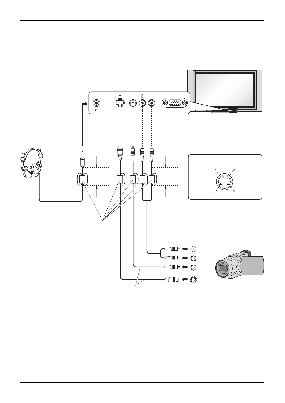
S VIDEO
AV3
VIDEO PCL R
Headphones / AV3 terminals Connection
Cable Connection
(Optional)
(Not supplied)
(
3.5 mm plug
Ferrite core (small size)
STR F TV/AV
AV3
S VIDEO
VIDEO L R/ /
Luminance in
Luminance earth
R - STANDBY
G - POWER ON
)
Less than
4" (10 cm)
Less than
4" (10 cm)
AV3 S VIDEO 4 pin socket
Chrominance in
Chrominance earth
A camcorder uses the AV3 terminal
on the front of this set.
(supplied)
R
AUDIO
L
OUT
VIDEO
OUT
S VIDEO
OUT
Camcorder
Connect the S-VIDEO or VIDEO terminal
Notes:
• Change the input signal to use the colour buttons on the remote control. (see page 17)
• The volume level of the headphones can be adjusted by selecting “Headphone volume” from the Sound menu.
• Additional equipment and cables shown are not supplied with this set.
11
Page 12

Cable Connection
PC Input terminals Connection
COMPUTER
Ferrite core (small size)
Conversion adapter
(if necessary)
(supplied)
4" (10 cm)
Audio
Stereo plug
Connect a cable which matches
the audio output terminal on the computer.
Less than
Less than
4" (10 cm)
Less than
4" (10 cm)
RGB
PC cable
Ferrite core (large size)
(supplied)
AV 3
S VIDEO VIDEO
D-sub 15p
L R
PC
Notes:
(1) Computer signals which can be input are those with a horizontal scanning frequency of 15 to 110 kHz and vertical
scanning frequency of 48 to 120 Hz. (However, the image will not be displayed properly if the signals exceed 1,200 lines.)
(2) The display resolution is a maximum of 640 × 480 dots when the aspect mode is set to “4:3”, and 852 × 480 dots
when the aspect mode is set to “16:9”. If the display resolution exceeds these maximums, it may not be possible
to show fine detail with sufficient clarity.
(3) Some PC models cannot be connected to the set.
(4) There is no need to use an adapter for computers with DOS/V compatible D-sub 15P terminal.
(5) The computer shown in the illustration is for example purposes only.
(6) Additional equipment and cables shown are not supplied with this set.
(7) Do not set the horizontal and vertical scanning frequencies for PC signals which are above or below the specified
frequency range.
(8) The Sound of the PC mode is combined with the Audio signal of AV3.
Signal Names for D-sub 15P Connector
1
2
678394510
15 14 13 12 11
Pin Layout for PC Input
Terminal
Pin No.
1
2
3
4
5
Signal Name
R
G
B
NC (not connected)
GND (Ground)
Pin No.
6
7
8
9
10
Signal Name
GND (Ground)
GND (Ground)
GND (Ground)
NC (not connected)
GND (Ground)
Pin No.
11
12
13
14
15
Signal Name
NC (not connected)
NC
HD/SYNC
VD
NC
12
Page 13
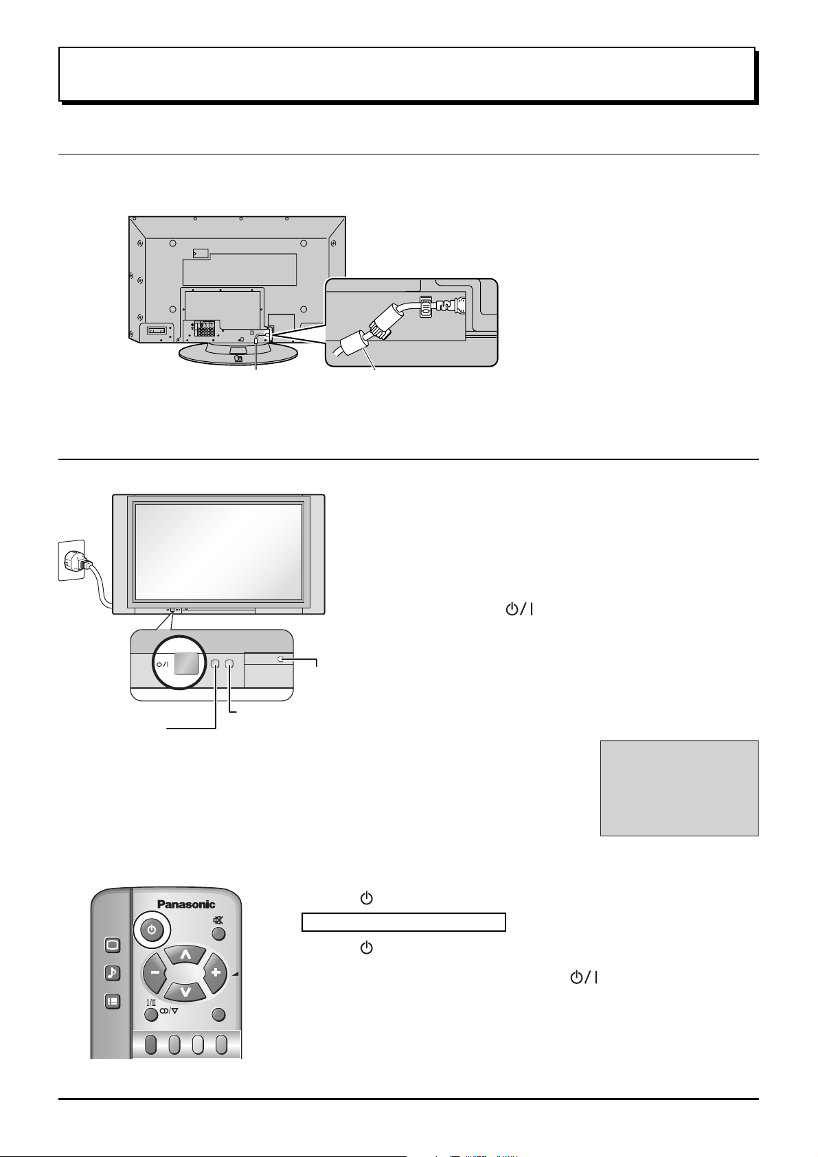
Power ON / OFF
AC cord Connection
Connecting the AC cord plug to the Plasma TV.
Ferrite core (large size) (supplied)
Power On/Off
Fix the AC cord plug securely to the
Plasma TV with the clamper.
Power Indicator
Remote Control Sensor
C.A.T.S sensor
Plasma C.A.T.S (Contrast Automatic Tracking System)
Plasma C.A.T.S automatically senses the ambient light
conditions and adjusts the brightness and gradation
accordingly, to optimise contrast.
(Effective when Viewing mode is set to Auto.)
Press the button on the remote control to turn the Plasma TV to standby.
Connect the plug to the Wall Outlet
Note:
Main plug types vary between countries. The power
plug shown at left may, therefore, not be the type fitted
to your set.
Press the switch on the Plasma TV to turn the
set on: Power-On.
Owner ID setting screen is displayed. (see page 23)
From the second time on, the below screen is
displayed for a while (setting condition is an example).
For VIDEO /
COMPONENT / TV
INPUT:
1
PICTURE
SOUND
SET UP
TV/AV
Power Indicator: Red (standby)
Press the button on the remote control to turn the Plasma TV on.
Turn the Plasma TV set off by pressing the switch on the Plasma TV,
when the Plasma TV is on or in standby mode.
Note:
The unit will still consume some power as long as the mains lead is still inserted
into the mains outlet.
13
Page 14

STR F TV/AV/ /
General Operation
Front panel controls and Remote control
Volume Up (+), Down (-)/
Programme Number Up ( ), Down ( )
Volume adjustment which uses these buttons is performed after
pressing Function button.
When programme number up ( ) or down ( ) button on the
front panel of the Plasma TV is pressed in stand-by mode,
the Plasma TV will be turned on.
STR F TV/AV
AV3
S VIDEO
VIDEO L R/ /
R - STANDBY
G - POWER ON
Plasma TV ON / Off Switch
Store
(see page 17, 19-21, 23, 35)
Function selection
Displays the On Screen
Volume
Display functions, press
repeatedly to select from the
available functions.
The following adjustments can
be accessed directly.
Contrast
Brightness
Colour
Sharpness
Notes:
• NTSC-Tint : Receiving NTSC signals.
• Tint : Receiving YUV(60Hz) signals.
• Tuning mode : Not displayed during AV mode.
Tuning mode
Balance
Treble
Bass
NTSC-Tint
(Tint)
TV/AVmode Selection
Press to select TV, AV input signal modes
sequentially.
Picture menu (see page 25, 26)
Sound menu (see page 27, 28)
Setup menu (see page 24)
Stereo Bilingual Sound Selection
(see page 37)
TV/TEXT Selection
(see page 34-36)
TEXT Favourite Page Selection
(see page 35)
PC input button (see page 30-32)
Surround On or Off (see page 28)
Aspect Control (see page 29)
MULTI PIP (Picture In Picture)
MULTI
14
Press to display main picture and sub picture (see page 33).
PIP
The main picture and sub picture can be changed by using Red, Green and Blue buttons.
[Picture out of Picture]
main picture sub picture main picture sub picture
A
B
Normal
Viewing
[Picture and Picture] [Picture in Picture]
main picture sub picture
MULTI
PIP
AB
Recall
Press to display the current system
status, for example, Programme number,
Channel number, Stereo mode, Picture
menu, Sound menu, Scan mode, Sound
system and colour system.
Resets all settings to their default leves
A
B
N (Normalise) button
Page 15

General Operation
Power (Stand-by)
The TV set must first be plugged into the wall outlet and
turned on at the power switch.
Press this button to turn the TV set On from Standby mode,
Press it again to turn the TV set to Standby mode.
Sound Mute
Press to mute the sound completely the “Mute” symbol will appear.
Press again to restore the previous sound level, and cancel the mute.
Programme Number Selection
Press to select the next higher or lower Programme number.
Volume Adjustment
Press to increase or decrease the sound volume level.
Volume 23
PICTURE
TV/AV Mode Selection
Press to select TV, AV input signal modes sequentially.
SOUND
SET UP
TV/AV
TEXT Index
(see page 36)
Channel Search
(see page 28)
Note:
It is also possible to turn the TV set
on from STANDBY mode by pressing
the “Direct Programme Number
Selection” Buttons (0-9) on the
Remote Control.
Coloured buttons used for
• AV Selection (see page 17)
• Channel Search (see page 28)
• Aspect Controls (see page 29)
• Multi PIP (see page 33)
• Teletext functions (see page 34-36)
TV/TEXT
PC
SURROUND
ASPECT
MULTI
PIP
INDEX HOLD
F. P.
CH SEARCH
1 2 3
4 5 6
7 8 9
0
DVD
REC-VCR
N
STR
STILL
TEXT Hold
(see page 35)
STILL
Press to freeze the picture, press again to return to watching the
current programme.
Direct programme Number
• Direct Programme Number Selection
You can select the number directly by pressing the corresponding
programme number buttons.
Programme Number 8.......
Programme Number 36..... 3 ,
Programme Number 124... 1 , 2 ,
8
6
4
Note:
When the Skip setting for Programme Number 100 through 125
is on, the channel selection time will be shortened, and thus you
can not input three digits at a time.
Store (see page 17, 19-21, 23, 35)
Stores some settings in Tuning menus
and Teletext.
VCR / DVD Operation (see page 37)
The Remote Control is capable of operating some functions of
selected VCR’s and DVD (Digital Versatile Disc) equipment. Some
VCR and DVD equipment have different functions, so to ensure
compatibility please refer to the equipment's instruction book or
consult your dealer for details.
15
Page 16

Using the On Screen Displays
Many features available on this set can be accessed via the On Screen Display menu system.
Use the remote control as shown below to access and adjust features as desired.
Press to display “Picture menu”
screen. (see page 25, 26)
Picture menu
Menu
Contrast
Brightness
Colour
Sharpness
NTSC-Tint/Tint
Colour temperature
P-NR
3D-COMB
Dynamic
Standard
Auto
On
Note:
NTSC-Tint/Tint: Displayed in
NTSC/YUV(60Hz) only.
During “PC” input signal
To Picture adjust menu
(see page 30, 31)
Picture
Normalise
Picture Mode
Contrast
Brightness
Sharpness
White balance
Advanced settings
Normal
Normal
25
0
0
Warm
Off
Press to select
“On”.
Press to enter
Advanced
settings .
Press to display “Sound menu”
screen. (see page 27, 28)
Sound menu
Menu
Volume
Bass
Treble
Balance
Headphone volume
Surround
PICTURE
SOUND
SET UP
TV/TEXT
PC
F. P.
Music
Off
INDEX HOLD
CH SEARCH
STILL
TV/AV
1 2 3
SURROUND
4 5 6
ASPECT
7 8 9
MULTI
PIP
0
Press to display “Setup menu”
screen. (see page 24)
During TV mode
Setup menu
Teletext
Off timer
Ch colour set
Child lock
Side panel
Power save
Tuning menu
Owner ID
TOP
Off
Off
High
Off
During AV mode
Setup menu
Teletext
Off timer
Ch colour set
Child lock
VCR/GAME
Colour system
Side panel
Power save
Owner ID
TOP
Off
Off
Off
Auto
High
Off
During “PC” input signal
(see page 32)
Setup
Normalise
H-Size
V-Size
H-Pos
V-Pos
Clock Phase
Sync
Normal
H & V
To Advanced settings
(see page 31)
Advanced settings
Normalise
W/B High R
W/B High B
W/B Low R
W/B Low B
Gamma
Normal
16
DVD
REC-VCR
N
0
0
0
0
0
2. 2
STR
Page 17

Using the On Screen Displays
TV/AV
1 2 3
4 5 6
F.P.
INDEX HOLD
CH SEARCH
STILL
PICTURE
SOUND
SET UP
TV/TEXT
PC
SURROUND
To T uning menu (see page 18)
Tuning menu
Sys select
Auto tuning
Manual tuning
Fine tuning
Skip
1 2 3
4 5 6
7 8 9
0
N
Australia
Off
STR
TV/AV
Auto tuning (see page 18) Manual tuning (see page 19)
29
AUTO SETUP IN PROGRESS
SEARCHING
SETUP : Return to tuning menu
TV/AV
: PLEASE WAIT
: To exit
29
Return
Manual tuning
Programme
down/up
Search
down/up
TV / AV -
Exit
‘STR’ Button-Store
Press to move the cursor up and down on the menu.
Press to access menus, adjust levels or to select from a range of options.
The STR button is used with a number of features to store settings after
adjustments have been made or options have been set.
The TV/AV button is used to exit the menu system and return to the
normal viewing screen.
Please refer to the On Screen Help
On Screen Help
An On Screen Help box is displayed whenever a
‘Instruction’ box
menu is displayed on the TV.
This Help box indicates which buttons on the remote
control are used to navigate the menu shown, see
above for descriptions of button functions.
Note:
The Help box is not shown in the menu pictures in this
instruction book due to space limitations.
Input signal selection by colour button
Input selection will be made by colour button, which match on screen button indication.
AV1
Colour Buttons
AV1AV2 AV3/PC
During AV1 input: Composite
AV4
Colour Bar Guide
During AV4 input: Composite / Component
During AV3 input: Composite
During AV2 input: Composite / Component
S Video
S Video
PC
Sound menu
Menu
Volume
Bass
Treble
Balance
Headphone volume
Surround
TV/AV
Music
Off
Select
Change
Exit
17
Page 18

STR F TV/AV/ /
Tuning Channels
Display the Tuning menu
1
SET UP
Press to display the Setup menu.
Press to select the Tuning menu.
Press to access Tuning menu.
Regional System Selection
2
Setup menu
Teletext
Off timer
Ch colour set
Child lock
Side panel
Power save
Tuning menu
Owner ID
TOP
Off
Off
High
Off
Access
Press to select the “Sys select”.
Press to select the appropriate system.
The system select indicator will change as follows.
NZ / INDONES Australia
Tuning menu
Sys select
Auto tuning
Manual tuning
Fine tuning
Skip
Australia
Off
System Select by Regional
Sys select
NZ / INDONES
Australia
New Zealand, Indonesia, etc.
Australia
Region
Auto tuning
This TV uses auto tuning to determine whether or not the TV can receive a broadcast signal which is being sent.
Before Auto tuning, Regional System must already be set.
Tuning menu
Press to select the “Auto tuning”.
Press to access to the “Auto tuning”.
Search Start.
29
Sys select
Auto tuning
Manual tuning
Fine tuning
Skip
Australia
Access
Off
AUTO SETUP IN PROGRESS
SEARCHING
: PLEASE WAIT
SETUP : Return to tuning menu
TV/AV : To exit
When a station is found.
The best tuning position is automatically
memorized.
Auto tuning (via front panel)
It is also possible to use the control panel buttons on the front of the TV to tune individual programme positions.
1 Press F (Front panel) until Tuning mode is reached.
2 Press / or / to access Tuning mode.
3 Press F (Front panel) to access Auto tune.
R - STANDBY
G - POWER ON
AV3
S VIDEO
STR F TV/AV
VIDEO L R/ /
4 Press / or / to start search.
Press F at any time to exit the Tuning menu.
18
Page 19

Manual tuning
STR F TV/AV/ /
Before Manual tuning, Regional System must already be set (see page 18).
Tuning Channels
Press to select the Manual tuning.
Press to access to the Manual tuning.
Press to select the desired Programme Number.
Press to select the higher or lower channel.
Search Start.
29
When a station
STR
Return
Manual tuning
Programme
down/up
Search
down/up
TV / AV -
Exit
‘STR’ Button-Store
is found.
When the desired station is found, press to store.
The tuning position is memorized.
TV/AV
Press to exit from the Tuning Menu.
This returns the set to the normal viewing condition.
Manual tuning (via front panel)
Tuning menu
Sys select
Auto tuning
Manual tuning
Fine tuning
Skip
Australia
Access
Off
It is also possible to use the control panel buttons on the front of the TV to tune individual programme positions.
1 Press F (Front panel) until Tuning mode is reached.
2 Press / or / to access Tuning mode.
3 Press
and Change TV system.
R - STANDBY
G - POWER ON
AV3
S VIDEO
STR F TV/AV
VIDEO L R/ /
to move between Change programme, Search
TV/AV
4 Press / or / to change programme position or start search.
When the desired station is found, press
The programme position will flash.
to store.
STR
Repeat above procedure to tune additional programme
positions.
Press F at any time to exit the Tuning menu.
Helpful Hint (
(1)
After the Manual tuning or the Auto tuning is finished, under the normal viewing condition press
/
Normalise
Normalisation)
this button to confirm the tuning condition for each Programme Number. If some Programme
Numbers are unused (no TV stations), it is possible to skip such Programme Numbers. Please
refer to the Programme Number Skip operation on page 21.
(2) When using a VCR without video and audio input/output terminals, it is convenient to connect the aerial cable as
indicated in the instruction manual of VCR and to set the designated channel to programme No. “0”. In that case,
perform manual tune after setting the colour system and sound system in advance. Further, in multi-system VCR,
it is more convenient to set the designated channel to several programme Numbers.
19
Page 20

Tuning Channels
Fine tuning
Under normal reception conditions this function is not required or necessary.
However, in areas of poor reception or constant interference, a slight adjustment of the tuning may improve the
picture and sound quality.
1
2
3
Press to select the Fine tuning.
Press until the clear picture is received.
STR
Press to store the Fine tuning.
This stores the Fine tuning to the selected Programme Number.
TV/AV
Press to exit from the Fine tuning.
This returns the set to the normal viewing condition.
Tuning menu
Sys select
Auto tuning
Manual tuning
Fine tuning
Skip
Australia
Off
How to Cancel the Fine tuning
Canceling previously adjusted (manually) fine tuning, means re-activating the AFT (Automatic Fine Tuning). Reactivating the Automatic Fine Tuning means allowing the set to automatically tune to the optimum tuning position, for
that programme Number.
Select the Programme Number which you would like to return
1
to Automatic Fine Tuning (cancel the manual fine tuning).
2
3
4
5
SET UP
STR
TV/AV
Press to display the Setup menu.
Proceed to the Tuning menu (see page 16, 17).
Press to select the Manual tuning.
Press to access to Manual tuning.
Press briefly to tune the best position.
Press to store the AFT.
This stores the re-activated AFT.
Press to exit from the Manual tuning.
This returns the set to the normal viewing condition.
Tuning menu
Sys select
Auto tuning
Manual tuning
Fine tuning
Skip
Australia
Access
Off
20
Page 21

Tuning Channels
Programme Number Skip
It is possible to skip Programme Number on which no TV stations are tuned appearing on the screen. The function is
only effective when selecting Programme Numbers by pressing the Programme Number Up or Down button either on
the TV set or on the Remote control.
Under the normal viewing condition press to select the Programme
1
Number you would like to skip.
5
2
3
4
SET UP
STR
TV/AV
1
3
Press to display the Setup menu.
Proceed to the Tuning menu (see page 16, 17).
Press to select the Skip.
Press to change the mode to “On”.
Press to store the Skip function.
Press to exit from the Skip.
This returns the set to the normal viewing condition.
24
Repeat Step1 to 4 for each Programme Number for which
the Skip function is desired.
Tuning menu
Sys select
Auto tuning
Manual tuning
Fine tuning
Skip
Australia
On
How to Cancel the Skip Function
1
2
STR
Press to select the Skip.
Press to change the mode to “Off”.
Press to store the Skip function.
Tuning menu
Sys select
Auto tuning
Manual tuning
Fine tuning
Skip
Australia
Off
21
Page 22

Tuning Channels
Channel Allocation
The receiving channels are as follows;
CH DISPLAY
0
1
2
3
4
5
6
7
11
12
13
14
15
16
19
20
21
22
23
24
28
NZ/INDONES AustraliaSys select
RECEIVE CHANNEL
–
1
2
11
–
–
–
–
–
–
–
–
21
–
0
1
2
3
4
5
S2
S10
6
9
9A
10
11
12
S11
57
58
59
62
63
69
70
73
74
75
76
77
78
79
80
81
89
90
91
92
93
94
95
96
97
98
99
100
S44
20
21
62
63
69
–
–
–
S'1
S'2
S'3
–
–
–
S1
S2
S10
S11
S12
S13
S14
S15
S16
S17
S18
S19
S20
S21
22
107
117
118
120
125
S41
–
–
69
–
–
–
–
–
–
–
Page 23

Owner ID
STR F TV/AV/ /
Owner ID allows you to enter a security code (Owner ID) and your personal details into the memory, so that in the
unfortunate event of theft it will help the police to trace the owner.
If you wish to check the personal details already entered into the
TV, press the F (Front panel) and hold for 5 seconds. The details
already entered are displayed on screen.
If Owner ID information was not entered when you switched on
R - STANDBY
G - POWER ON
AV3
S VIDEO
STR F TV/AV
VIDEO L R/ /
your TV for the first time or it is necessary to alter some of the
information, Owner ID can be re-accessed via the Tuning menu.
1
2
SET UP
Press to display the Setup Menu.
Press to select the “Owner ID”.
Press to access “Owner ID”.
If the Owner ID has previously been set, enter the PIN NUMBER (using 0
to 9 on the remote control) followed by
STR
to proceed, this will take you to
the NAME option.
If no Owner ID has previously been set, enter the required 4 digit Owner
ID PIN NUMBER (using 0 to 9 on the remote control).
If a 4 digit PIN NUMBER was entered above, you will be taken automatically
to the NAME line.
If not, move to the NAME line by using or .
Change character by using or .
Setup menu
Teletext
Off timer
Ch colour set
Child lock
Side panel
Power save
Tuning menu
Owner ID
Owner ID
PIN NUMBER:
NAME:
HOUSE NO:
POSTCODE:
0123456789
You now have the opportunity
to enter your details and
help the police crack crime
see instruction book
Return
‘STR’ Button-Store Owner ID
TOP
Off
Off
High
Off
Access
Change
Select
TV / AV -
For future reference,
write your PIN NUMBER here
character
character
Exit
:
Select character position by using or .
Repeat above until NAME, HOUSE NUMBER and POSTCODE are
entered.
STR
Press
to store the details.
Press again when you are asked, “Are you sure?”
The Owner ID is now stored.
23
Page 24

Setup Adjustment
1
SET UP
Press to display the Setup menu.
2
Press to select the desired function.
Press to adjust or change the
function.
Setup menu
3
Teletext
Off timer
Ch colour set
Child lock
Side panel
Power save
Tuning menu
Owner ID
TV/AV
TOP
Off
Off
High
Off
Press to go back to watching TV.
Teletext
Allows you to choose 2 modes. (see page 34-36)
TOP List
Off timer
Power save
By reducing the brighness of picture, power consumption
be lower.
On Off
During AV mode, the appearance of the Setup menu will
differ from that of the TV mode, with the following function
adjustments becoming available.
Setup menu
Teletext
Off timer
Ch colour set
Child lock
VCR/GAME
Colour system
Side panel
Power save
Owner ID
TOP
Off
Off
Off
Auto
High
Off
VCR/GAME
Reproduction of irregular signals, such as certain TV
games and rental video tapes, may be improved.
Switches the TV off within a preset time which you can
choose from between 0 to 90 minutes in 15 minutes
intervals.
Off
90
3015
45
6075
Ch colour set
Colour density varying between broadcast channels can
be adjusted to three levels for each reception channel.
Child lock
If the Child-Lock function is set On, picture and sound of
the TV/AV mode being viewed will disappear and a Black
screen will appear.
Side panel
Do not display a picture in 4:3, 14:9 mode for an extended
period, as this can cause an after-image to remain on the
side panels either side of the display field.
To prevent the appearance of
such an after-image, illuminate
the side panels.
Side panel
Colour system
During AV mode, Colour system is displayed.
If a clear picture with current colours cannot be obtained
when a Broadcast or AV signal is received, then the colour
system will change as shown.
Auto PAL
NTSC3.58 NTSC4.43
PAL and NTSC 3.58 are different colour signal broadcast
transmission systems applicable to differing countries.
NTSC 4.43 is a trick playback mode used in special VCR
to playback NTSC recorded video tapes through PAL
television equipment.
Off Low Mid High
24
4 : 3
Page 25

Picture Adjustment
1
PICTURE
Press to display the Picture Menu.
2
Press to select the desired function.
Press to adjust or change the function.
3
TV/AV
Press to go back to watching TV.
Menu
Picture menu mode will be memorized for each TV, AV1, AV2, AV3 and
AV4 mode.
• You can change the level of each Item (Contrast, Brightness, Colour,
Sharpness, NTSC-Tint, Colour temperature and P-NR) for each Picture
Menu (Dynamic, Standard, Cinema and Auto).
Picture Menu Function
Dynamic
Standard
For viewing in brighter environments.
This menu selects a higher than normal
levels of Brightness and Contrast.
For viewing in normal (evening lighting)
environments.
This menu selects the normal levels of
Brightness and Contrast.
Picture menu
Menu
Contrast
Brightness
Colour
Sharpness
Colour temperature
P-NR
3D-COMB
Picture menu
Menu
Contrast
Brightness
Colour
Sharpness
Colour temperature
P-NR
3D-COMB
Menu
Menu
Dynamic
Standard
Auto
On
Dynamic
Standard
Auto
On
Dynamic
Standard
Cinema
Auto
Ideal for movies.
Can be selected for VIDEO/COMPONENT.
Automatically selects the mode that best
suits the brightness of the environment.
Contrast, Brightness, Colour, Sharpness, NTSC-Tint (Tint)
Increase or decrease the levels of Contrast, Brightness, Colour and
Sharpness options according to your personal preference.
With an NTSC signal source connected to the TV, the picture hue can be
adjusted to suit your taste.
Item FunctionEffect
Contrast
Brightness
Colour
Sharpness
NTSC-Tint
(Tint)
Less More
Darker Brighter
Less More
Less More
Reddish Greenish
Adjust for contrast.
Adjusts for easier viewing of dark
pictures such as night scenes and hair.
Adjusts slightly to a lighter colour.
Displays a sharp image.
Adjust for proper skin colour.
Menu
Menu
Picture menu
Menu
Contrast
Brightness
Colour
Sharpness
NTSC-Tint/Tint
Colour temperature
P-NR
3D-COMB
Cinema
Auto
Dynamic
Standard
Auto
On
Notes:
• When set to Multi PIP mode, the main and sub pictures are both adjusted simultaneously.
• When the TV is receiving NTSC signals, NTSC-Tint is displayed.
• When the TV is receiving YUV(60Hz) signals, Tint is displayed.
25
Page 26

Picture Adjustment
Colour temperature
Set the overall colour tone of the picture.
Press to switch between modes.
P-NR (Picture Noise Reduction)
Automatically reduces undesired picture noise.
Press to switch between modes.
Off
Auto
3D-COMB
If the 3D-COMB function is On, dot interference or
cross colour will be reduced.
Press to switch between On and Off.
On Off
Note:
Displayed only when receiving PAL or NTSC signals.
Not displayed during S-Video input and YUV input mode.
Strong
Weak
Picture menu
Menu
Contrast
Brightness
Colour
Sharpness
CoolWarmStandard
Colour temperature
P-NR
3D-COMB
Picture menu
Menu
Contrast
Brightness
Colour
Sharpness
Colour temperature
P-NR
3D-COMB
Picture menu
Menu
Contrast
Brightness
Colour
Sharpness
Colour temperature
P-NR
3D-COMB
Dynamic
Standard
Auto
On
Dynamic
Standard
Auto
On
Dynamic
Standard
Auto
On
Helpful Hint (
Normalization)
By pressing the Normal “N” Button on the Remote Control while the Picture menu is displayed, the selected menu will
be changed to the Normal Mode.
Normalization will not occur if the menu is not displayed when the “N” Button is pressed.
The Normal mode is the factory preset condition. Returning to this original condition is called “Normalization”.
26
Page 27

Sound Adjustment
SOUND
Press to display the Sound Menu.
Press to select the desired function.
Press to adjust or change the function.
TV/AV
Press to go back to watching TV.
Sound menu
Menu
Volume
Bass
Treble
Balance
Headphone volume
Surround
Music
Off
Note:
Some features are only available with the Surround feature switched off. Press
Menu
Sound menu mode will be memorized for each TV, AV1, AV2, AV3 and AV4
mode.
• You can change the level of Bass and Treble for each Sound Menu (Music,
Cinema and News).
Sound Menu Function
Music
Amplifies the Low frequencies and outputs
optimum sound.
For music programmes for example.
News
Human voices (middle pitch sounds) will
sound more clear.
Cinema
For movie and drama programmes.
Volume, Bass, Treble, Balance, Headphone volume
Item FunctionEffect
Volume
Bass
Less More
Less More
Adjusts output volume.
Adjusts low sounds.
SURROUND
to switch between On and Off.
Sound menu
Menu
Volume
Bass
Treble
Balance
Headphone volume
Surround
Menu
Menu
Menu
Sound menu
Menu
Volume
Bass
Treble
Balance
Headphone volume
Surround
Music
Off
Music
News
Cinema
Music
Off
Treble
Balance
Headphone
volume
Less More
Left SP. Right SP.
Less More
Adjusts high sounds.
Adjust left and right volumes.
Adjust Headphone volume.
Note:
When using one of the double window features, note
that the headphones will relay the soundtrack for the
programme in the main window, not the smaller
window.
27
Page 28

Sound Adjustment / Channel Search
Surround
SURROUND
Press to switch between On and Off.
Sound menu
OR
SOUND
Press to display the Sound Menu.
Press to select the Surround function.
Menu
Volume
Bass
Treble
Balance
Headphone volume
Surround
Press to switch between On and Off.
The benefits of surround sound are enormous. You can be completely enveloped in sound; just as if you were at a concert
hall or cinema.
The surround effect can be obtained without the use of external surround speakers.
Music
Off
Helpful Hint (
Normalization)
By pressing the Normal “N” Button on the Remote Control while the Sound menu is displayed, the selected menu will
be changed to the Normal Mode.
Normalization will not occur if the menu is not displayed when the “N” Button is pressed.
The Normal mode is the factory preset condition. Returning to this original condition is called “Normalization”.
Channel Search
Select the desired channel after displaying still pictures of all stored channels on the screen divided into 9 sections.
INDEX
CH SEARCH
Red
Press to display divided-by-9 screen of all
channels.
Press to select channel number.
The yellow channel number changes
successively each time the button is
pressed.
1
4
7
Select
2
5
8
OK
3
6
9
Exit
28
Press to view the selected channel
Green
normally.
To exit a channel search that is in progress.
Press to exit from channel search.
Blue
OR
INDEX
CH SEARCH
Press to exit from the feature.
Red Green Yellow Blue
Page 29

Aspect Controls
ASPECT
Press to select the different Aspect options.
TV/TEXT
PC
F.P.
INDEX HOLD
CH SEARCH
STILL
Auto
Zoom3
16:9
Zoom2
14:9 Just
Zoom1
4:3
1 2 3
SURROUND
ASPECT
MULTI
PIP
4 5 6
7 8 9
PC mode :
Zoom 4:3
Just16:9
0
Notes:
• Simply press
•
16:9 picture has been used to illustrate all of the aspect modes described in this section.
The on screen selector keys (corresponding to the four coloured buttons on the remote control) appear for some
Aspect functions and disappear after a few seconds. If you would like to select an operation when the keys are not
shown, press
Auto
ASPECT
to display mode information in the top left of the screen.
ASPECT
once more and the keys will reappear.
ExplanationPictureMode
The Auto position can be set to 16 : 9. When a
wide screen signal is detected at the Video
terminal the TV will select the 16:9 aspect ratio.
16 : 9
14 : 9
Just
4 : 3
Zoom1
Zoom2,
Zoom3
16:9 Signal
16:9 Signal 4:3 Signal
Zoom1
Zoom2
4:3 Signal
The 16:9 option will display the picture at its
maximum size. Signals in the 4:3 format will be
stretched to fit the picture.
The 14:9 option will display a 4:3 signal in
simulated wide screen. The picture is slightly
stretched. It is also slightly cropped top and
bottom.
Just gives you a best fit option when showing
4:3 on wide screen. The centre of the picture is
not affected but there is some stretching at the
edges.
This option will display a standard 4:3 picture
without any stretching or compression. There
will be vertical gray lines down either side of the
picture.
This option allows you to magnify the picture.
The picture becomes larger and larger when
you change the mode Zoom2 and Zoom3.
Notes:
• ASPECT operations cannot be made during progressive (Y, PB, PR) or 1080i signal input.
• The Red and Green buttons let you change the mode during the mode displays (except PC mode).
29
Page 30

PC mode Adjustments
When you switch to PC input (AV3 / PC), Picture menu will be changed as shown bellow.
Sound menu will not be accessible in PC mode.
1 Press TV/AV button.
PICTURE
1 Press to display the picture menu
screen.
2 Press Yellow (AV3) button to
access ‘PC’ mode.
2 Press to select the menu to adjust.
Adjust the desired level by looking
at the picture behind the menu.
Press the left
modes.
Picture
Normalise
Picture Mode
Contrast
Brightness
Sharpness
White balance
Advanced settings
Advanced settings On
Enables fine picture adjustment at a
professional level (see next page).
Normal
Normal
25
0
0
Normal
On
Press to select “On”.
Press to enter
Advanced settings .
1 2 3
4 5 6
7 8 9
0
or right
Cinema Dynamic
Auto
Automatically selects the mode that best suits the
brightness of the environment.
Normal
For viewing in standard (evening lighting)
environments.
This menu selects the normal levels of
Brightness and Contrast.
Dynamic
For viewing in brighter environments.
This menu selects higher than normal
Brightness and Contrast
Cinema
Ideal for movies.
OR
1 Press PC button to access
‘PC’ mode.
Note:
Press PC button again to return to
watching the current programme.
button to switch between
Auto Normal
.
levels of
Advanced settings
Normalise
W/B High R
W/B High B
W/B Low R
W/B Low B
Gamma
Advanced settings Off
Displays images with settings of the
Picture menu.
Helpful Hint (
While the “Picture” menu is displayed, if either the N button on the remote control is pressed at any time or the or
button is pressed while the yellow cursor is at the “Normalise” position, then all adjustment values are returned to the
factory settings.
Normal
0
0
0
0
0
2. 2
/
Normalise
Note:
If you would like to change the picture and colour of
the selected Picture menu to something else, adjust
using the items in the Picture menu. (see next page)
Press the left
modes.
Normal Cool Warm
or right
button to switch between
Normalisation)
30
Page 31

PC mode Adjustments
Item Effect Function
Contrast
Brightness
Sharpness
Note:
In Picture, there is not a noticeable change even when contrast is increased
with a bright picture or reduced with a dark picture.
Less
Darker
Less
Adjusts the proper brightness and
More
density for the room.
Adjusts for easier viewing of dark pictures
Brighter
such as night scenes and black hair.
More
Adjusts picture sharpness.
Note:
You can change the level of each
function (Contrast, Brightness,
Sharpness) for each Picture menu.
Advanced settings
Item Effect Details
W/B High R Adjusts the white balance for light red areas.
W/B High B Adjusts the white balance for light blue areas.
Less More
Less More
W/B Low R Adjusts the white balance for dark red areas.
W/B Low B Adjusts the white balance for dark blue areas.
Gamma S Curve
Note:
Carry out “W/B” adjustment as follows.
Adjust the white balance of the bright sections using the “W/B High R” and “W/B High B” settings.
A
Adjust the white balance of the dark sections using the “W/B Low R” and “W/B Low B” settings.
B
Repeat steps A and B to adjust.
C
Steps A and B affect each other’s settings, so repeat each step in turn to make the adjustment.
Less More
Less More
Down Up
2.0
2.2
2.5
/
Normalise
Normalisation)
Helpful Hint (
While the “Advanced settings” menu is displayed, if either the N button is pressed at any time or the or button is
pressed while the yellow cursor is at the “Normalise” position, then all adjustment values are returned to the factory
settings.
31
Page 32

PC mode Adjustments
Adjusting Position and Size
Adjusting screen
SET UP
1 Press to display the Setup menu.
2 Press to select H-Pos/H-Size/V-
Pos/V-Size/Clock Phase.
Setup
Normal
H & V
3
Normalise
H-Size
V-Size
H-Pos
V-Pos
Clock Phase
Sync
Press to adjust Pos./Size.
TV/AV
Press to exit from adjust mode.
1 2 3
4 5 6
7 8 9
0
1 Press TV/AV button.
2 Press Yellow (AV3) button to
access ‘PC’ mode.
OR
1 Press PC button to access
‘PC’ mode.
Note:
Press PC button again to return to
watching the current programme.
H-Size
V-Size
H-Pos
V-Pos
Clock Phase
When the Position Left
When the Position Left
When the Position Left
When the Position Left
Flickering and distortion can be eliminated by using the Position Left “-” or Right “+” button
to carry out adjustment.
“-”
button is pressed
“-”
button is pressed.
“-”
button is pressed.
“-”
button is pressed.
When the Position Right
When the Position Right
When the Position Right
When the Position Right
“+”
button is pressed.
“+”
button is pressed.
“+”
button is pressed
“+”
button is pressed.
Sync
Helpful Hint (
While the “Setup” menu is displayed, if either the N button on the remote control is pressed at any time or the or
button is pressed while the yellow cursor is at the “Normalise” position, then all adjustment values are returned to the
factory settings.
H & V : To synchronize by the horizontal and vertical signals from your PC.
on G : To synchronize by the green signal form your PC (if available).
/
Normalise
Normalisation)
32
Page 33

Multi Screen
Multi PIP
Press
or picture and picture feature.
TV/TEXT
PC
SURROUND
ASPECT
MULTI
PIP
INDEX HOLD
F.P.
CH SEARCH
STILL
1 2 3
4 5 6
7 8 9
0
The on screen selector keys for the features (corresponding to the four coloured buttons
on the remote control) appear and disappear after a few seconds. If you would like to
select an operation when the keys are not shown, press
reappear.
Allows two pictures to be viewed
at the time.
Use the remote control to select
a TV channel or an AV source
to appear in the main window.
MULTI
PIP
to select the current programme, the picture in picture, picture out of picture,
MULTI
once more and the keys will
PIP
2
POP PAP Change
Red Green Yellow Blue
POP PAP Change
AV1
Press the Red button:
Red
PAP PIP Change
Picture out of Picture (POP)
Press the Green button:
Green
2
PIP POP Change
Picture and Picture (PAP)
MULTI
PIP
Press to exit.
AV12
AV1
Picture in Picture (PIP)
Press the Blue button:
Blue
Main picture
A B
POP PAP Change POP PAP Change
Each time the main picture and the sub picture are swapped.
Notes:
• MULTI PIP operations cannot be made during PC mode, or progressive
signal or 1080i signal input (Y, PB, PR).
• This TV has one tuner. When the main and sub pictures are TV mode,
these are the same TV channel.
Sub picture
Changing the channels
Select channels.
1 2 3
4 5 6
7 8 9
0
OR
Press the Number buttons on
the remote control.
Changing the mode
• Main picture
TV/AV
Press to select input mode.
TV AV
• Sub picture
MULTI
PIP
Press to display the colour bar.
TV/AV
During the colour bar is displayed, press
to select desired input mode.
TV AV1 AV2
AV3AV4
33
Page 34

Teletext
PICTURE
SOUND
SET UP
TV/AV
• Teletext features may vary depending on the Broadcasting Companies and is only
available if the channel selected is transmitting Teletext.
• Pressing the Picture button whilst in Teletext operation will display the contrast function
with a cyan bar, press or to alter the setting as required.
• Pressing the Setup button whilst in Teletext operation will display special function
options at the bottom of the screen.
• Pressing the Sound button whilst in Teletext operation will display the volume function
with a green bar, press or to alter the setting as required.
TV/TEXT
PC
F.P.
CH SEARCH
INDEX HOLD
1 2 3
SURROUND
4 5 6
ASPECT
MULTI
PIP
7 8 9
0
TV / Teletext mode
TV/TEXT
Page Selection
1 2 3
4 5 6
7 8 9
0
STILL
What is List mode?
In List mode, four differently coloured page numbers are situated at the bottom of the
screen. Each of these numbers can be altered and stored in this set’s memory.
What is TOP mode?
In TOP mode, four differently coloured subjects are situated at the bottom of the
display. To access more information about one of these subjects, press the appropriately
coloured button. This facility enables fast access to information on the subjects shown.
Note:
When watching TV in 4:3 or zoom mode, pressing TV/TEXT button will display teletext
page momentarily in that aspect before switching to normal teletext picture size.
TV/TEXT
Press
to switch between the current programme, teletext and the picture and
text feature.
Pages can be selected in two ways:
a. Press or to increase or decrease the page number by one.
b. By entering the page number, using 0 -9 on the remote control.
FulI / Top / Bottom
Press
SET UP
Green
Press the Green button again to expand the BOTTOM half.
Press again to return to normal (FULL) size.
Reveal
SET UP
Red
Press
reveal hidden words e.g. quiz page answers. Press again to hide.
Red / Green / Yellow / Blue buttons
In TOP mode they correspond to the differently coloured subjects.
Red
Green
Yellow
Blue
In List mode they correspond to the differently coloured page numbers.
34
SET UP
to display special functions, followed by the Green button.
SET UP
to display special functions, followed by the Red button to
Page 35

Teletext
It is not possible to change the programme position when in News flash, Update or Sub Coded Page Access operation.
List Store
In List mode the four page numbers can be altered (programme positions 1 - 25
1 2 3
4 5 6
7 8 9
0
Red
Green
Yellow
STR
only).
Blue
To do this, press one of the four coloured buttons and enter the new page number.
Press and hold
STR
, the page number will change to white indicating that the page
is stored.
Hold
HOLD
Favourite Page (F.P.)
STR
F. P.
Blue
1 2 3
4 5 6
7 8 9
0
Update Display
News Flash
Update
HOLD
Press
to hold the Teletext page when viewing multi-page information.
Press again to return to automatic page update.
Stores a favourite page in memory for instant recall. To store such a page, this set
must be in List mode, and the programme position must be from 1 - 25.
Press the Blue button, select the page number, then press and hold
STR
.
The page number is now stored.
F. P.
Press
Update Display
Press
to recall this page.
SET UP
to display special functions, followed by the Yellow button to view the
TV picture whilst searching for a Teletext page.
When found, the screen will display the page number at the top left.
Press the Yellow button to view the page.
TV/TEXT
Press
to return to normal TV operation.
SET UP
Yellow
News Flash
When a news flash page has been selected, press
SET UP
, Yellow, to view the TV
picture. When an update is received, the page number will be displayed on
screen.
Press the Yellow button to display the News Flash.
TV/TEXT
Press
to return to normal TV operation.
Update
SET UP
Press
, Yellow to see the update of information on certain pages.
When an update is received, the page number will be displayed at the top left of
the screen.
Press the Yellow button to view the page.
TV/TEXT
Press
to return to normal TV operation.
35
Page 36

Teletext
Index
INDEX
Sub Coded Page Access
SET UP
Blue
1 2 3
4 5 6
7 8 9
0
When in Top operation
INDEX
Press
to return to the main index page.
Depending on the way information is transmitted, this may have to be pressed
more than once to return to the main index page.
When Teletext information exceeds more than one page, it may take some time
for the automatic changing of the sub pages to reach the sub page you require.
It is possible to enter your required sub page and continue watching the normal
programme until the correct sub page is found.
Select the required page number using buttons 0 - 9.
If the top of the page indicates that sub pages are being transmitted yet the page
does not change, then the number at the top of the page is there to indicate that
the broadcaster has updated the page's contents, there are no sub pages.
SET UP
Press
followed by the Blue button; T∗∗∗∗ will be displayed at the top right of
the screen.
Enter desired sub page number before the T∗∗∗∗ disappears. To select page 6
enter 0, 0, 0 and 6.
(If in List mode, a ‘T’ will appear in the current box at the bottom).
Yellow
Press the Yellow button to view a normal TV programme.
(Press
SET UP
, Yellow in List mode).
When the page is available, press the Yellow button to view the page.
To clear the page perform one of the following:
• Press
• Select a new page number.
• Press
SET UP
.
TV/TEXT
to return to normal TV operation.
36
Page 37

Advanced Remote Control Operation
MULTI
Stereo Bilingual Sound Selection
When you receive the stereo/bilingual sound system, sound output modes can be selected
by pressing the stereo/bilingual sound selection button.
Audio Signal
Mode Indicator
NICAM .......used in New Zealand, Singapore and Hong Kong
Type of broadcast
Mode Indicator
A2(German) .......used in Australia, Malaysia, Thailand, Indonesia etc.
Type of broadcast
Mode Indicator
STEREO MAIN I SUB II MONO
II
STEREO
Regular broadcast
(Standard Audio)
No Indicator
Regular broadcast
(Standard Audio)
No Indicator
I
Regular + NICAM MONO I
(MAIN I )
I
BILINGUAL or DUAL MONO:
MAIN I / SUB II
I II
NICAM STEREO
NICAM DUAL MONO
(MAIN I / SUB II )
I
II
Notes:
• If the stereo signal is poor or the receiving conditions are not optimum or if STEREO:MONO automatic switching
occurs, it is recommended you switch from STEREO to MONO.
• Even when the contents of the receiving signal undergo changes, selection mode is kept intact.
• When the receiving conditions deteriorate, listening will be easier if the mode is set to the “MONO” position, using
the stereo/bilingual sound selection button.
• “DUAL”, also known as “DUAL MONO” or as “BILINGUAL” is not currently transmitted in some countries.
VCR / DVD Control
The Remote Control is capable of operating some functions of selected VCRs and DVD (Digital Versatile Disc)
equipment. Some VCR and DVD equipment have different functions. So to ensure compatibility please refer to the
equipment's instruction book or consult your dealer for details.
1
2
3
4
5
6
7
8
9
Button
DVD
VCR
REC
Standby
VCR / DVD selection switch
Play
Stop
Fast Forward / Cue
Rewind / Review
Pause / Still
VCR : Programme number Up / Down
DVD : Skip
Record
PIP
0
3
6
4
1
DVD
REC-VCR
9
7
N
STR
5
2
8
Function
37
Page 38

Advanced Remote Control Operation
Manufacturer setting
Remote Control Operation is possible for the VCR’s and DVD’s of the various manufacturers.
After completion of setting, execute the various operations .
PC
1 Press to select VCR / DVD.
1 2 3
SURROUND
ASPECT
MULTI
PIP
4 5 6
7 8 9
2
2 While pressing the VCR / DVD Power button,
0
2
DVD
REC-VCR
N
STR
Note:
After setting, execute operation confirmation.
If there is no operation, set a different code.
1
2
1 2 3
4 5 6
7 8 9
0
press the manufacturer code (enter the two digit
code), and press the VCR / DVD Stop button.
VCR
Manufacturer
Panasonic/
National
AIWA
FUJITSU
HITACHI
JVC
MITSUBISHI
Code
10,11,12,13
15,16
20
25,26,27
30,31,32
35,36
Manufacturer
NEC
ORION
PHILIPS
SANYO
SHARP
SONY
TOSHIBA
Code
40,41,42,43
45,46
50
55,56,57,58
60,61
65,66,67
70,71
DVD
Manufacturer
Panasonic
70, 71
Code
Helpful Hint
(1) The respective VCR / DVD manufacturer code is cancelled when battery has been exchanged.
Please set it again.
(2) Depending on the model, operation of VCR’s or DVD’s of the manufacturers listed above may not be possible.
(3) In some cases, new products may not be operative.
(4) It will not operate with other than the above manufactures.
38
Page 39

Troubleshooting
If there is a problem with your set please refer to the table below to determine the symptoms, then carry out the
suggested check. If this does not solve the problem, please contact your local Panasonic dealer, quoting the model
number and serial number (both found on the rear of this TV).
Symptoms
Picture Sound
Snowy Picture
Multiple Image
Interference
Normal Picture
No Picture
No Colour
Noisy Sound
Normal Sound
Noisy Sound
No Sound
No Sound
Normal Sound
Checks
Aerial location, direction or connection
Aerial location, direction or connection
Electrical appliances
Cars/Motorcycles
Fluorescent lights
Volume level
Sound mute switched on
This set to AV mode
Not plugged into A.C. outlet
Not switched on
Picture / Sound controls set at minimum levels
Check if in stand-by mode
Colour Controls set at minimum levels
Poor or Distorted
Picture
No Colour
Plasma TV panel
Symptoms
Some parts of the screen do
not light up
After-images appear
Weak or
No Sound
Noisy Sound
Retune Channel (s)
Colour System/Sound System
Check
The plasma TV panel is manufactured using an extremely high level of precision
technology, however, sometimes some parts of the screen may be missing
picture elements or have luminous spots. This is not a malfunction.
Do not allow a still picture to be displayed for an extended period, as this can
cause a permanent after-image to remain on the Plasma TV.
Examples of still pictures include logos, video games, computer images, teletext
and images displayed in 4:3 mode.
Note:
The permanent after-image on the Plasma TV resulting from fixed image use is
not an operating defect and as such is not covered by the Warranty.
This product is not designed to display fixed images for extended periods of
time.
Notes:
• External surfaces of the unit may become hot during operation. But this is completely normal.
• See label on the base of this equipment for ratings and other information.
39
Page 40

For your Guidance
Service
Before requesting service, please refer to the
troubleshooting guide on previous page to determine
the symptoms. To obtain service please contact your
local Panasonic dealer quoting the model number and
serial number (both are located at the rear of this TV).
Sleep Feature
If the set is not switched off when the TV station stops
transmitting, it will automatically go to standby mode
after 30 minutes, This function will not operate when this
TV is in AV mode.
Last position Memory
Certain functions have a last position memory, i.e. the
setting at the time of switch - off will be the setting used
when this set is switched on again:
Programme
AV position
Volume
Status
Aspect
Standby
Picture menu
Sound menu
Setup menu
Input signal can be displayed
Applicable input signals for PC Input (D-sub 15P) (∗ Mark)
Signal name
1 640 × 400 @70 Hz 31.47 70.00 ∗
2 640 × 480 @60 Hz 31.47 59.94 ∗
3 Macintosh13” (640 × 480) 35.00 66.67 ∗
4 640 × 480 @75 Hz 37.50 75.00 ∗
5 852 × 480 @60 Hz 31.50 60.00 ∗
6 800 × 600 @60 Hz 37.88 60.32 ∗
7 800 × 600 @75 Hz 46.88 75.00 ∗
8 800 × 600 @85 Hz 53.67 85.06 ∗
9 Macintosh16” (832 × 624) 49.73 74.55 ∗
10 1,024 × 768 @60 Hz 48.36 60.00 ∗
11 1,024 × 768 @70 Hz 56.48 70.07 ∗
12 1,024 × 768 @75 Hz 60.02 75.03 ∗
13 1,024 × 768 @85 Hz 68.68 85.00 ∗
14 Macintosh21” (1,152 × 870) 68.68 75.06 ∗
15 1,280 × 1,024 @60 Hz 63.98 60.02 ∗
16 1,280 × 1,024 @75 Hz 79.98 75.03 ∗
17 1,280 × 1,024 @85 Hz 91.15 85.02 ∗
18 1,600 × 1,200 @60 Hz 75.00 60.00 ∗
Horizontal Vertical
frequency(kHz) frequency(Hz)
PC
Note:
Signals without above specification may not be displayed properly.
40
Page 41

Specifications
Power Source
Power Consumption
Normal use
Standby
Power-OFF
Plasma Display panel
Drive method
Aspect Ratio
Contrast Ratio
Screen size
(No.of pixels)
Sound
Speaker
Audio Output
Headphone
Applicable signals
Colour System
Scanning format
PC signals
Receiving
System
RF Channels
OUTPUT
AUDIO OUT
VIDEO OUT
INPUT
AV1-Rear
AV2-Rear
AV3-Front
AV4-Rear
PC
ANT-Rear
Operating Conditions
Accessories Supplied
Remote Control Transmitter
Batteries
Fixing band
Ferrite core
Dimensions ( W × H × D )
Mass (Weight)
TH-37PA20 TH-42PA20
220 V - 240 V 50 Hz / 60 Hz A.C.
243 W 313 W
1.8 W
1.0 W
AC type
16:9
4000:1
37-inch 42-inch
818 mm (W) × 461 mm (H) × 939 mm (diagonal) 920 mm (W) × 518 mm (H) × 1056 mm (diagonal)
408,960 (852 (W) × 480 (H)) [2,556 × 480 dots]
L: Woofer (40 mm) × 4 + Tweeter (35 mm) × 1
R: Woofer (40 mm) × 4 + Tweeter (35 mm) × 1
16 W (8 W + 8 W) (10 %THD)
M3 (3.5 mm) Jack × 1
NTSC, PAL, PAL60, Modified NTSC
525 (480) / 60i · 60p, 625 (575) / 50i · 50p,1125/50i, 1125/60i
VGA display
VGA, SVGA, XGA,
SXGA, UXGA ······ (compressed)
Horizontal scanning frequency 15 - 110 kHz
Vertical scanning frequency 48 - 120 Hz
1. PAL B/G Reception of Off air broadcasts
Playback from Video Tape Recorders
2. NTSC 4.43 Playback from Special Video Tape
3. NTSC 3.58 Recorders and Special Video Disc Players
4. PAL 60Hz (Via the AV Sockets)only.
VHF 0 to 12 PAL B
UHF 21 to 69 PAL G
S'1 to S'3 HYPER TUNER
S1 to S41
AUDIO L-R (RCA Pin Type × 2) 0.5 Vrms
VIDEO (RCA Pin Type) 1.0 Vp-p (75 Ω)
VIDEO (RCA Pin Type) 1.0 Vp-p (75 Ω)
S-VIDEO (MINI DIN 4-pin) Y:1.0 Vp-p (75 Ω) C:0.286 Vp-p (75 Ω)
AUDIO L-R (RCA Pin Type × 2) 0.5 Vrms
VIDEO (RCA Pin Type) 1.0 Vp-p (75 Ω)
AUDIO L-R (RCA Pin Type × 2) 0.5 Vrms
Y 1.0 Vp-p (including synchronization)
PB/PR ±0.35 Vp-p
VIDEO (RCA Pin Type) 1.0 Vp-p (75 Ω)
S-VIDEO (MINI DIN 4-pin) Y:1.0 Vp-p (75 Ω) C:0.286 Vp-p (75 Ω)
AUDIO L-R (RCA Pin Type × 2) 0.5 Vrms
VIDEO (RCA Pin Type) 1.0 Vp-p (75 Ω)
AUDIO L-R (RCA Pin Type × 2) 0.5 Vrms
Y 1.0 Vp-p (including synchronization)
PB/PR ±0.35 Vp-p
(HIGH-DENSITY D-SUB 15PIN) R,G,B/0.7 Vp-p (75-ohm)
HD, VD/1.0 - 5.0 Vp-p (high impedance)
AUDIO L-R (RCA Pin Type) 0.5 Vrms (high impedance)
UHF/VHF
Temperature : 0 ° - 40 °C
Humidity : 20 % - 80 % RH (non-condensing)
EUR511281
2 × R6 Size
(TMME203 or TMME 187) × 1
Large size × 3, Small size × 5
1070 mm × 596 mm × 99 mm 1170 mm × 658 mm × 99 mm
29.5 kg 35.0 kg
Note:
Design and specifications are subject to change without notice. Mass and dimensions shown are approximate.
41
Page 42

Page 43

Page 44

Customer’s Record
The model number and serial number of this product can be found on its rear panel. You should note this
serial number in the space provided below and retain this book, plus your purchase receipt, as a permanent
record of your purchase to aid in identification in the event of theft or loss, and for Warranty Service purposes.
Model Number Serial Number
Matsushita Electric Industrial Co., Ltd.
Web Site : http://www.panasonic.co.jp/global/
2004 Matsushita Electric Industrial Co., Ltd. All Rights Reserved.
MBS1003S1044
 Loading...