

Panasonic TH-32LRU30, TH-42LRU30, TH-37LRU30 User Manual
Owner’s Manual
Hospitality LCD HDTV
Model No.
TH-32LRU30
TH-37LRU30
TH-42LRU30
English
Thank you for purchasing this Panasonic product.
Please read these instructions before operating your set
and retain them for future reference. The images shown in
this manual are for illustrative purposes only.
TQB2AA0623
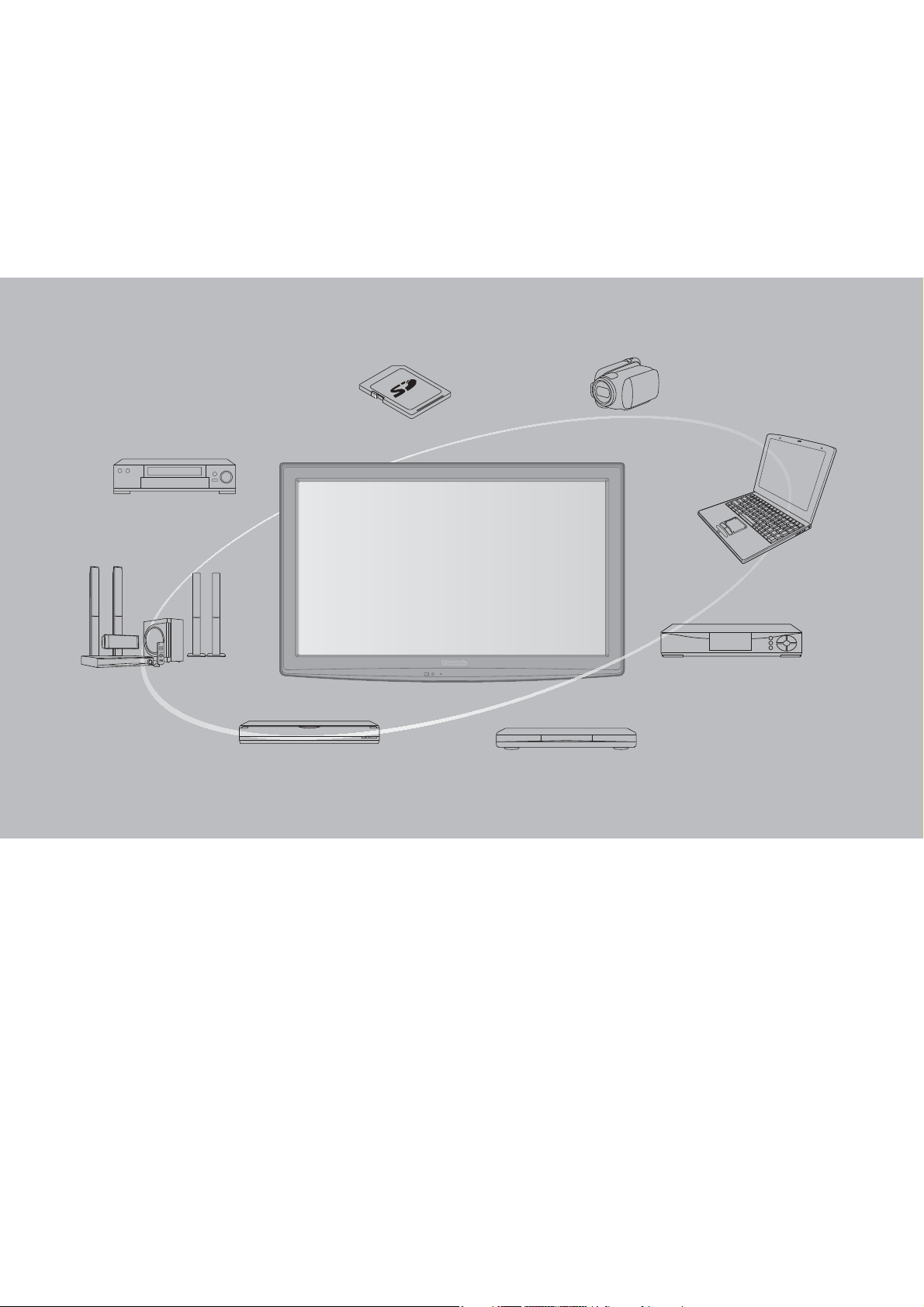
Experience an amazing level of
multimedia excitement
Enjoy rich multimedia
SD memory card
VCR
Amplifier with
Speaker system
DVD Recorder/
Blu-ray Disc recorder
This product incorporates the following software or technology:
(1) the software developed independently by or for Panasonic Corporation,
(2) the software owned by third party and licensed to Panasonic Corporation,
(3) the software developed by the Independent JPEG Group,
(4) the software developed by the FreeType Project.
DVD Player/
Blu-ray Disc player
Camcorder
Personal computer
Cable box
2
HDMI, the HDMI logo and HighDefinition Multimedia Interface are
trademarks or registered trademarks
of HDMI Licensing LLC in the United
States and other countries.
SDXC Logo is a trademark of SD3C, LLC.
Contents
This product qualifies for ENERGY
STAR in the factory default setting
and this is the setting in which
energy savings will be achieved.
Any modifications to the factory
default setting or other factory
default settings could result in
greater energy consumption beyond
levels that meet ENERGY STAR
qualifications.
Manufactured under license from Dolby Laboratories.
Dolby and the double-D symbol are trademarks of Dolby
Laboratories.
Please read before using the unit
Safety Precautions ········································· 4
Quick Start Guide
Accessories/Optional Accessory ····················7
Connections ················································· 10
Identifying Controls ······································ 13
Enjoy your TV!
Basic Features
TV operation ················································14
Watching Videos and DVDs ························· 15
Displaying PC screen on TV ························16
Viewing from an SD card ····························· 18
Advanced Features
How to Use Menu Functions ························ 19
Lock ·····························································22
Editing and Setting Channels ·······················24
Closed Caption ············································26
Input Labels ·················································27
Guest Menu ·················································28
Quick Start
Guide
Viewing Advanced FAQs, etc.
FAQs, etc.
Ratings List for Lock ····································29
Technical Information ··································· 30
FAQ ······························································ 34
Care and Cleaning ·······································36
Specifications ··············································· 37
Limited Warranty ·········································· 38
3
Safety Precautions
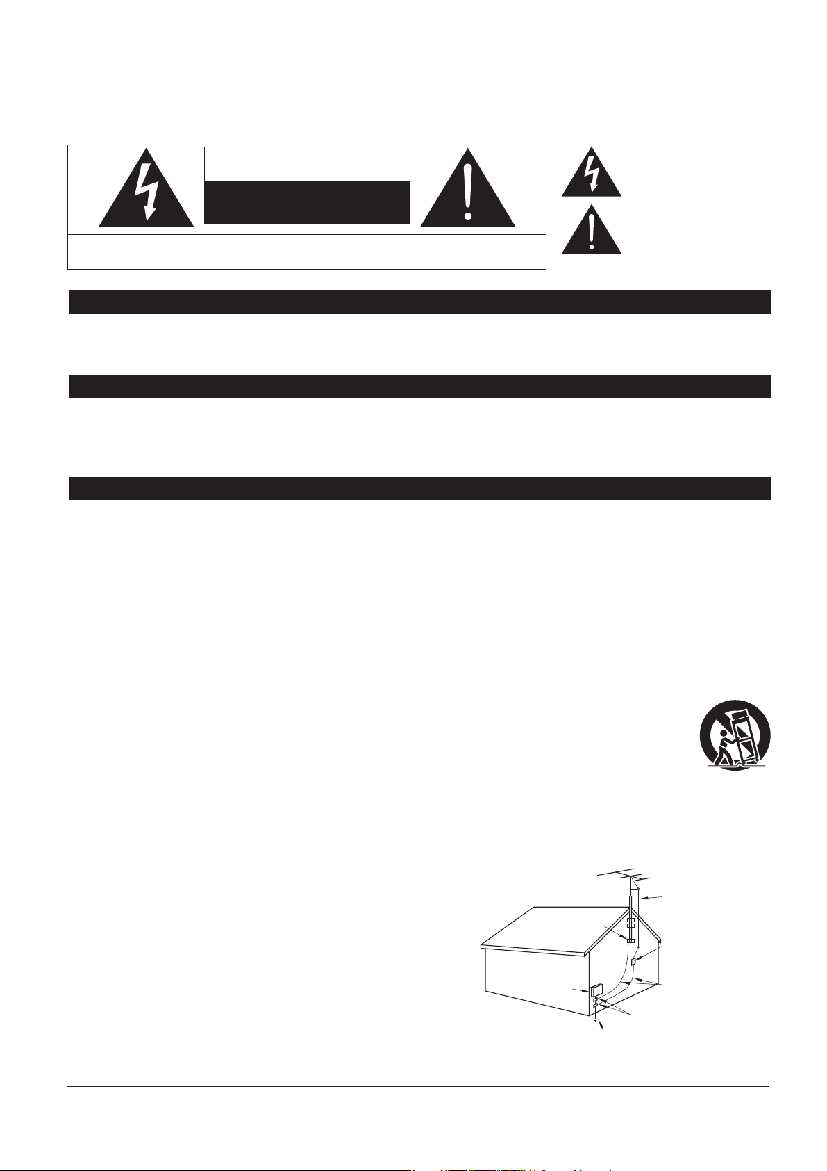
The lightning flash with arrowhead
CAUTION
RISK OF ELECTRIC SHOCK
WARNING: To reduce the risk of electric shock, do not remove cover or back.
No user-serviceable parts inside. Refer servicing to qualified service personnel.
This reminder is provided to direct the CATV system installer’s attention to Article 820-40 of the NEC that provides guidelines for
proper grounding and, in particular, specifies that the cable ground shall be connected to the grounding system of the building, as
close to the point of cable entry as practical.
Slots and openings in the cabinet and the back or bottom are provided for ventilation, and to ensure reliable operation of the LCD
TV and to protect it from overheating. These openings must not be blocked or covered. There should be at least 10 cm of space
from these openings. The openings should never be blocked by placing the LCD TV on a bed, sofa, rug or other similar surface.
This LCD TV should not be placed in a built-in installation such as a bookcase unless proper ventilation is provided.
1) Read these instructions.
2) Keep these instructions.
3) Heed all warnings.
4) Follow all instructions.
5) Do not use this apparatus near water.
6) Clean only with dry cloth.
7) Do not block any ventilation openings. Install in accordance with the manufacturer’s instructions.
8) Do not install near any heat sources such as radiators, heat registers, stoves or other apparatus (including amplifiers) that
produce heat.
9) Do not defeat the safety purpose of the polarized or grounding-type plug. A polarized plug has two blades with one wider
than the other. A grounding type plug has two blades and a third grounding prong. The wide blade or the third prong are
provided for your safety. If the provided plug does not fit into your outlet, consult an electrician for replacement of the
obsolete outlet.
10) Protect the power cord from being walked on or pinched particularly at plugs, convenience receptacles, and
the point where they exit from the apparatus.
11) Only use attachments / accessories specified by the manufacturer.
12) Use only with the cart, stand, tripod, bracket or table specified by the manufacturer, or sold with the
apparatus. When a cart is used, use caution when moving the cart / apparatus combination to avoid injury
from tip-over.
13) Unplug this apparatus during lightning storms or when unused for long periods of time.
14) Refer all servicing to qualified service personnel. Servicing is required when the apparatus has been damaged in any
way, such as power-supply cord or plug is damaged, liquid has been spilled or objects have fallen into the apparatus, the
apparatus has been exposed to rain or moisture, does not operate normally, or has been dropped.
15) Operate only from the type of power source indicated on the marking label. If you are not sure of the type of power supplied
to your home consult your television dealer or local power
company.
16) Follow all warnings and instructions marked on the LCD TV.
17) Never push objects of any kind into this LCD TV through cabinet
slots as they may touch dangerous voltage points or short out
parts that could result in a fire or electric shock. Never spill liquid
of any kind on the LCD TV.
18) If an outside antenna is connected to the television equipment,
be sure the antenna system is grounded so as to provide some
protection against voltage surges and built up static charges.
In the U.S. Section 810-21 of the National Electrical Code
provides information with respect to proper grounding of the mast
and supporting structure, grounding of the lead-in wire to an
antenna discharge unit, size of grounding conductors, location of
antenna discharge unit, connection to grounding electrodes, and
requirements for the grounding electrode.
DO NOT OPEN
Note to CATV System Installer
Important Safety Instructions
Secure Ventilation
EXAMPLE OF ANTENNA
GROUNDING AS PER
(NEC) NATIONAL
ELECTRICAL
CODE
GROUND CLAMP
ELECTRIC
SERVICE
EQUIPMENT
POWER SERVICE GROUNDING
ELECTRODE SYSTEM
(NEC ART 250, PART H)
within a triangle is intended to tell the
user that parts inside the product are a
risk of electric shock to persons.
The exclamation point within a
triangle is intended to tell the
user that important operating and
servicing instructions are in the
papers with the appliance.
ANTENNA
LEAD-IN WIRE
ANTENNA
DISCHARGE UNIT
(NEC SECTION 810-20)
GROUNDING
CONDUCTORS
(NEC SECTION 810-21)
GROUND CLAMPS
4

19) An outside antenna system should not be located in the vicinity of overhead power lines, other electric light, power circuits,
or where it can fall into such power lines or circuits. When installing an outside antenna system, extreme care should be
taken to keep from touching such power lines or circuits as contact with them might be fatal.
20) Unplug this LCD TV from the wall outlet and refer servicing to qualified service personnel under the following conditions:
a. When the power cord or plug is damaged or frayed.
b. If liquid has been spilled into the LCD TV.
c. If the LCD TV has been exposed to rain or water.
d. If the LCD TV does not operate normally by following the operating instructions.
Adjust only those controls that are covered by the operating instructions as improper adjustment of other
e. If the LCD TV has been dropped or the cabinet has been damaged.
f. When the LCD TV exhibits a distinct change in performance - this indicates a need for service.
When replacement parts are required, be sure the service technician uses replacement parts specified by the manufacturer that
21)
have the same characteristics as the original parts. Unauthorized substitutions may result in fire, electric shock, or other hazards.
22) WARNING: TO REDUCE THE RISK OF FIRE OR ELECTRIC SHOCK, DO NOT EXPOSE THIS APPARATUS TO RAIN,
23) WARNING: SMALL PARTS CAN PRESENT CHOKING HAZARD IF ACCIDENTALLY SWALLOWED. KEEP SMALL
24) WARNING: To prevent the spread of fire, keep candles or other open flames away from this product at all
25) CAUTION: The Power switch on this unit will not completely shut off all power from AC outlet. Since the power
26) CAUTION: TO PREVENT ELECTRIC SHOCK, DO NOT USE THIS PLUG WITH A RECEPTACLE OR OTHER OUTLET
27) CAUTION: USE WITH OTHER STAND MAY RESULT IN INSTABILITY POSSIBLY CAUSING INJURY.
28) CAUTION: DANGER OF EXPLOSION IF BATTERY IS INCORRECTLY REPLACED. REPLACE ONLY WITH THE SAME
29) CAUTION: This LCD TV is for use only with the following optional accessory. Use with any other type of optional
controls may result in damage and will often require extensive work by a qualified technician to restore the
LCD TV to normal operation.
MOISTURE, DRIPPING OR SPLASHING.
DO NOT PLACE LIQUID CONTAINERS (FLOWER VASES, CUPS, COSMETICS, ETC.) ABOVE THE SET
(INCLUDING ON SHELVES ABOVE, ETC.).
PARTS AWAY FROM YOUNG CHILDREN.
DISCARD UNNEEDED SMALL PARTS AND OTHER OBJECTS, INCLUDING PACKAGING MATERIALS
AND PLASTIC BAGS/SHEETS TO PREVENT THEM FROM BEING PLAYED WITH BY YOUNG CHILDREN,
CREATING THE POTENTIAL RISK OF SUFFOCATION.
times
cord serves as the main disconnect device for the unit, you will need to unplug it from the AC outlet to
shut down all power.
Therefore, make sure the unit has been installed so that the power cord can be easily unplugged from AC outlet
in case of an accident. To avoid fire hazard, the power cord should also be unplugged from the AC outlet when
left unused for a long period of time (for example, when on vacation).
UNLESS THE BLADES CAN BE FULLY INSERTED TO PREVENT BLADE EXPOSURE.
OR EQUIVALENT TYPE.
accessories may cause instability which could result in the possibility of injury.
(All of the following accessories are manufactured by Panasonic Corporation)
• Wall-hanging bracket: TY-WK3L2RW
Always be sure to ask a qualified technician to carry out set-up.
NOTE: This equipment is designed to operate in North America and other countries where the broadcasting system and AC
house current are exactly the same as in North America.
FCC STATEMENT
This equipment has been tested and found to comply with the limits for a Class B digital device, pursuant to Part 15 of the FCC
Rules. These limits are designed to provide reasonable protection against harmful interference in a residential installation.
This equipment generates, uses and can radiate radio frequency energy and, if not installed and used in accordance with the
instructions, may cause harmful interference to radio communications. However, there is no guarantee that interference will not occur
in a particular installation. If this equipment does cause harmful interference to radio or television reception, which can be determined
by turning the equipment off and on, the user is encouraged to try to correct the interference by one or more of the following
measures:
• Reorient or relocate the receiving antenna.
• Increase the separation between the equipment and receiver.
• Connect the equipment into an outlet on a circuit different from that to which the receiver is connected.
• Consult the dealer or an experienced radio/TV technician for help.
This device complies with Part 15 of the FCC Rules. Operation is subject to the following two conditions: (1) This device may
not cause harmful interference, and (2) this device must accept any interference received, including interference that may cause
undesired operation.
FCC Caution:
To assure continued compliance, follow the attached installation instructions and use only shielded interface cables
when connecting to computer or peripheral devices. Any changes or modifications not expressly approved by
Panasonic Corp. of North America could void the user’s authority to operate this device.
FCC Declaration of Conformity
Model No. TH-32LRU30, TH-37LRU30, TH-42LRU30
Responsible Party: Panasonic Corporation of North America
Three Panasonic Way, 2F-5, Secaucus, NJ 07094
Contact Source: Panasonic Solutions Company
5

Safety Precautions (Continued)
CEA CHILD SAFETY NOTICES: Flat panel displays are not always supported on the proper stands or
installed according to the manufacturer’s recommendations. Flat panel displays that are inappropriately
situated on dressers, bookcases, shelves, desks, speakers, chests or carts may fall over and may cause
personal injury or even death.
The consumer electronics industry (of which Panasonic is a member) is committed to making home
entertainment enjoyable and safe. To prevent personal injury or death, be sure to follow the following safety
guidelines:
TUNE INTO SAFETY:
x One size does NOT fit all. Follow the
of your flat panel display.
x Carefully read and understand all enclosed instructions for proper use of this product.
x Don’t allow children to climb on or play with furniture and television sets.
x Don’t place flat panel displays on furniture that can easily be used as steps, such as a chest of drawers.
x Remember that children can become excited while watching a program, especially on “larger than life”
flat panel displays. Care should be taken to install the display where it cannot be pushed, pulled over,
or knocked down.
x Care sh
cannot be pulled or grabbed by curious children.
ould be taken to route all cords and cables connected to the flat panel display so that they
manufacturer’s recommendations for the safe installation and use
WALL MOUNTING: IF YOU DECIDE TO WALL MOUNT YOUR FLAT PANEL DISPLAY, ALWAYS:
x Use a mount that has been recommended by the display manufacturer and/or listed by an independent
laboratory (such as UL, CSA, ETL).
x Follow all instructions supplied by the display and wall mount manufacturers.
x If you have any doubts about your ability to safely install your flat panel display, contact your retailer
about professional installation.
x Make sure the wall where you are moun
designed to be mounted to walls with steel studs or old cinder block construction. If you are unsure,
contact a professional installer.
x A minimum of two people are required for installation. Flat panel displays can be heavy.
The American Academy of Pediatrics discourages television viewing for children younger than
two years of age.
ting the display is appropriate. Some wall mounts are not
6
Accessories/Optional Accessory
Accessories
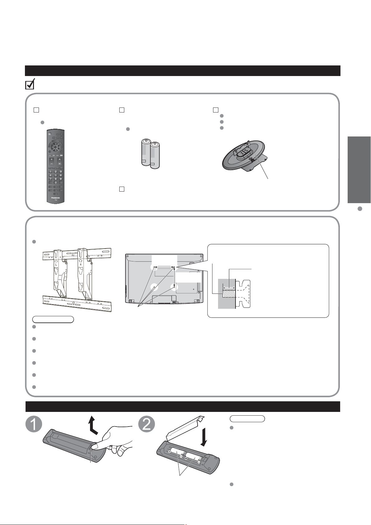
Check you have all the items shown.
Accessories
Remote Control
Transmitter
N2QAYB000485
Batteries for the
Remote Control
Transmitter (2)
AA Battery
Operating Instructions
Pedestal
TBL2AX0032 (TH-32LRU30)
TBL2AX0048 (TH-37LRU30)
TBL2AX0049 (TH-42LRU30)
Guide
How to assemble (p. 8)
Quick Start
Accessories/Optional Accessory
Optional Accessory
Wall-hanging bracket
TY-WK3L2RW
WARNING
Customer assumes liability if mounting the unit themselves or if a Panasonic bracket is not used. Any damage resulting
from not having a professional installer mount your unit will void your warranty.
Always be sure to ask a qualified technician to perform any necessary set-up. Incorrect fitting may cause equipment to
fall, resulting in injury and product damage.
Do not mount the unit directly below ceiling lights (such as spotlights, floodlights or halogen lights) which typically give off
high heat. Doing so may warp or damage plastic cabinet parts.
Take care when fixing wall brackets to the wall. Always ensure that there are no electrical cables or pipes in the wall
before hanging bracket.
When using an angled-type wall hanging bracket, please ensure that there is sufficient space for the connecting cables
so that they do not press against the wall when the TV is tilted forward.
For safety reasons, remove units no longer being used from their wall-mounted locations.
Please contact your nearest Panasonic dealer to purchase the recommended
wall-hanging bracket. For additional details, please refer to the wall-hanging
bracket installation manual.
Back of the TV
7.9 ”
(200 mm)
7.9 ”
(200 mm)
Holes for wall-hanging bracket
installation
Screw for fixing the TV onto the
wall-hanging bracket
(not supplied with the TV)
Depth of screw:
Minimum: 0.39” (10.0 mm)
Maximum: 0.47” (12.0 mm)(32”/37”)
1.57” (40.0 mm) (42”)
M6
(View from the side)
Hook
Open
Installing the remote’s batteries
Close
Note the correct polarity
(+ or -).
Incorrect installation may cause
Do not burn or break batteries.
Caution
battery leakage and corrosion,
resulting in damage to the remote
control.
Do not mix old and new batteries.
•
Do not mix different battery types (such
•
as alkaline and manganese batteries).
Do not use rechargeable (Ni-Cd)
•
batteries.
7
Accessories/Optional Accessory
(Continued)
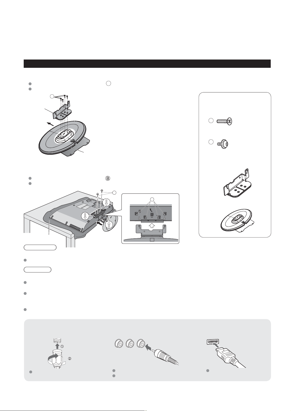
Attaching the pedestal to TV
Assembling the pedestal
Fix securely with assembly screws A. (Total 4 screws)
Tighten screws firmly.
A
Accessories
Bracket
Front
Assembly screws
(4 of each)
A
XSS4+16FJK
M4 × 16
B
Base
(Image: TBL2AX0032)
Set-up
Fix securely with assembly screws . (Total 4 screws)
Tighten screws firmly.
B
B
Foam mat or thick
soft cloth
WARNING
Do not disassemble or modify the pedestal.
Otherwise the TV may fall over and become damaged, and personal injury may result.
Caution
Do not use any other TV and displays.
Otherwise the TV may fall over and become damaged, and personal injury may result.
Do not use the pedestal if it becomes warped or physically damaged.
If you use the pedestal when it is physically damaged, personal injury may result. Contact your nearest Panasonic
Dealer immediately.
During set-up, make sure that all screws are securely tightened.
If sufficient care is not taken to ensure screws are properly tightened during assembly, the pedestal will not be strong
enough to support the TV, and it might fall over and become damaged, and personal injury may result.
THE2AC004J
M4 × 12
Bracket (1)
Base (1)
8
Reference of connection
Antenna terminal Pin terminals HDMI terminal
greenbluered
green
Firmly tighten by hand.
Match colors of plugs and terminals.
Insert firmly.
Insert firmly.
Location
Place the TV at a comfortable distance for viewing. Avoid placing it where sunlight or other bright light (including reflections)
will fall on the screen. Use of some types of fluorescent lighting can reduce remote control transmitter range. Adequate
ventilation is essential to prevent an internal component failure. Keep away from areas of excessive heat or moisture.
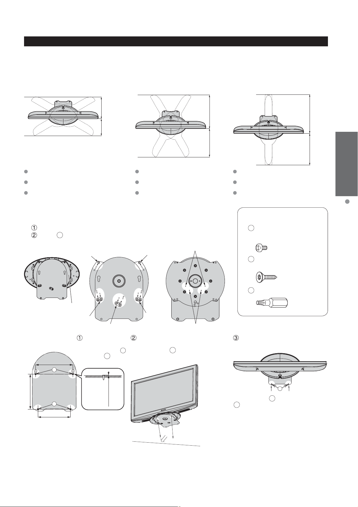
Adjust the stand to your desired angle.
The stand angle can be rotate 30°/60°/90° to the right/left. (see Control rotation angle)
[Rotation angle: 30°]
[Rotation angle: 60°]
[Rotation angle: 90°]
ab
TH-32LRU30 a: 9.8 ” (248 mm)
b: 7.6 ” (193 mm)
TH-37LRU30 a: 11.0 ” (279 mm)
b: 8.8 ” (222 mm)
TH-42LRU30 a: 12.5 ” (316 mm)
b: 9.8 ” (248 mm)
Control rotation angle
The rotation angle can be controlled at 30° or 60°.
It is not necessary to attach the screws for the 90° angle rotation.
Temporarily remove the 5 screws shown below.
Attach A screws (2) to each angle control position.
[Bottom view]
[Front of swivel plate] [Back of swivel plate]
1
TH-32LRU30 a: 15.0 ” (381 mm)
b: 12.8 ” (323 mm)
TH-37LRU30 a: 17.1 ” (433 mm)
b: 14.7 ” (373 mm)
TH-42LRU30 a: 19.0 ” (483 mm)
b: 16.5 ” (418 mm)
2
[For 30°]
ab
ab
Quick Start
Guide
TH-32LRU30 a: 17.3 ” (439 mm)
b: 14.2 ” (360 mm)
TH-37LRU30 a: 19.7 ” (500 mm)
b: 16.4 ” (416 mm)
TH-42LRU30 a: 21.9 ” (555 mm)
b: 18.4 ” (467 mm)
Accessories/Optional Accessory
Accessories
A
Screws (2)
XSN3+4FJ
M3 × 4
B
Wood screw (4)
THM2AB001
C
Bit (for pedestal) (1)
Swivel plate
3
Set-up
[Back of fixed plate]
6.5” (165 mm)
a
6.1” (155 mm)
Place the TV set in a position where it will not protrude from the table when swiveled.
•
Make sure there is enough space between the TV set and wall, so that when the TV set is swiveled it does not hit the wall.
•
b
5.7” (144 mm)
Use the specialized bit
(supplied) in position
and screw in
screw (2).
4
a
B
0.079” – 0.091”
(2 – 2.3 mm)
,
wood
5
[For 60°]
Align the swivel hole in the bottom of the
swivel plate with
screwed in previously, and place the TV
set onto the swivel plate.
Slide the TV set forwards until it stops,
then fix it in place.
B
wood screw that was
[View from above]
b
Lastly, use the C specialized bit to fix
B
Wood screw in place.
9
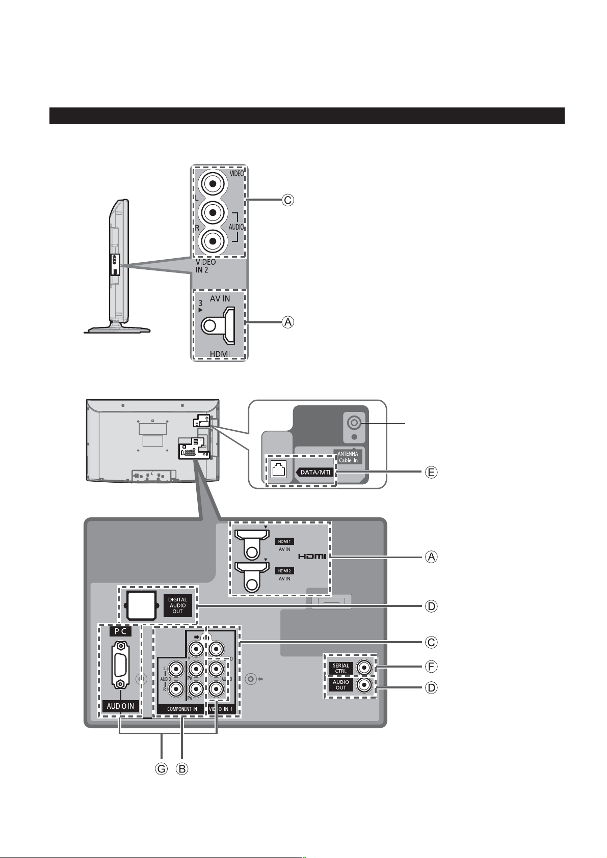
Connections
Connection panel
Side panel
Back panel
RF connection*
10
* For more details on the external equipment’s connections, please refer to the operating manuals for the equipment.

Connecting Antenna
VHF/UHF Antenna
NTSC (National Television System Committee):
•
Conventional broadcasting
ATSC (Advanced Television Systems Committee):
•
Digital TV Standards include digital high-definition television (HDTV), standard-definition television (SDTV), data
broadcasting, multichannel surround-sound audio and interactive television.
AC 110-127 V
60 Hz
Power Cord
(Connect after all the
other connections.)
Cable
You need to subscribe to a cable TV service to enjoy viewing their programming.
•
You can enjoy high-definition programming by subscribing to a high-definition cable service.
•
The connection for high-definition can be done with the use of HDMI or Component Video cable. (see below)
To view high-definition programming select the correct video input. (p. 15)
•
Back of the TV
VHF/
Cable TV
UHF A
or
ntenna
Example of connections
Quick Start
Guide
Connections
To use HDMI terminals
Side panel Back panel
HDMI
AV OUT
HDMI cable
Connecting to the HDMI terminals will enable you to enjoy high-definition digital images and high-quality sound.
The HDMI connection is required for a 1080p signal.
To use COMPONENT terminals
Y
green
blue
red
white
red
green
blue
red
white
red
B
P
COMPONENT
VIDEO OUT
PR
L
AUDIO
OUT
R
gre
blu
re
d
whit
re
d
en
e
e
AV Equipment
e.g. Blu-ray Disc
player
AV Equipment
e.g. Blu-ray Disc
player
Note
Not all cables and external equipment shown in this book are supplied with the TV.
For more details on the external equipment’s connections, please refer to the operating manual for the equipment.
11
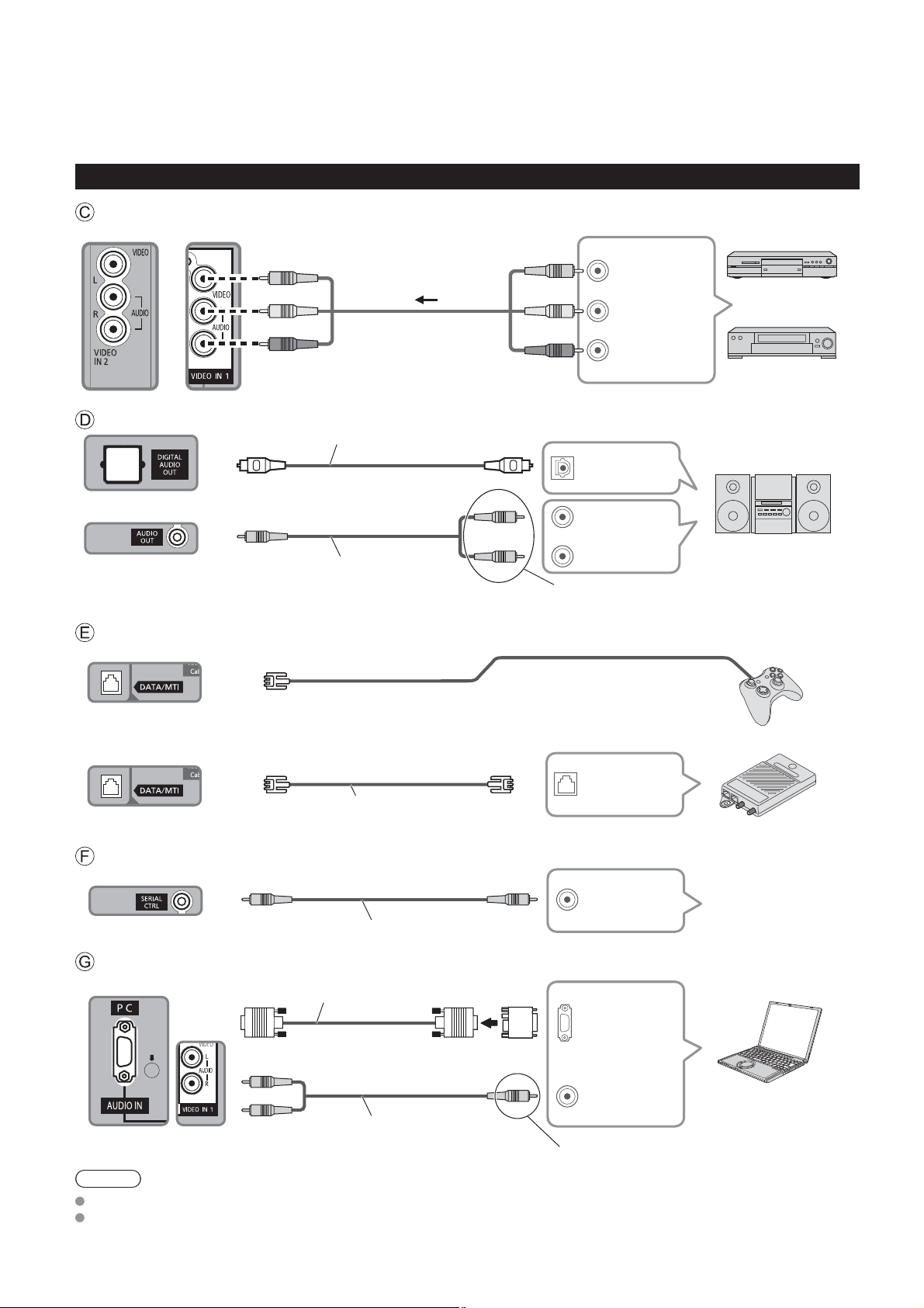
Connections (Continued)
Example of connections
To use COMPOSITE terminals
Side panel Back panel
AV Equipment
yellow
w
hit
e
r
ed
To use AUDIO OUT terminals
Optical digital audio cable
Audio cable
To use DATA/MTI terminal
Internal TA
yellow
y
ellow
COMPOSITE
L
red
ite
OUT
R
white
wh
red
OPTICAL IN
AUDIO IN
Connect a cable which matches
the audio in terminal on the unit.
e.g. DVD Recorder
or
e.g. VCR
Audio equipment
External device
12
External TA
MTI OUT
Cross Cable
e.g. Game controller
Terminal adapter
To use SERIAL terminal
SERIAL OUT
RS232C cable
External controller
e.g. Bed side controller
To use PC terminal
Conversion adapter
RGB PC cable
Audio cable
Note
Not all cables and external equipment shown in this book are supplied with the TV.
For more details on the external equipment’s connections, please refer to the operating manual for the equipment.
(if necessary)
PC OUT
AUDIO OUT
Connect a cable which matches
the audio out terminal on the PC.
PC
 Loading...