

Panasonic TH-37LRT12U, TH-37LRT12M, TH-37LRT12A, TH-32LRT12U, TH-32LRT12M Service Manual
...
Order Number PTWTV0909004CE
High Definition Hospitality LCD Display
Model No. TH-37LRT12U/M/A
TH-32LRT12U/M/A-B
TABLE OF CONTENTS
1 Safety Precautions----------------------------------------------- 3
1.1. General Guidelines---------------------------------------- 3
2 Warning-------------------------------------------------------------- 4
2.1. Prevention of Electrostatic Discharge (ESD)
to Electrostatically Sensitive (ES) Devices---------- 4
2.2. About lead free solder (PbF)---------------------------- 5
3 Service Navigation----------------------------------------------- 6
3.1. Important Notice (TH-32LRT12U/M/A-B)------------ 6
3.2. Different P.C.B. --------------------------------------------6
3.3. Service Hint (TH-32LRT12U/M/A-B)------------------ 7
3.4. Service Hint (TH-37LRT12U/M/A)--------------------- 8
3.5. Applicable signals ----------------------------------------- 9
4 Specifications ----------------------------------------------------10
4.1. TH-32LRT12U/M/A-B------------------------------------10
4.2. TH-37LRT12U/M/A---------------------------------------11
5 Factory Mode -----------------------------------------------------12
5.1. How to enter into Factory Mode ----------------------12
5.1.1. Key command ----------------------------------------12
5.1.2. Contents of adjustment mode --------------------12
5.2. How to exit -------------------------------------------------13
PAGE PAGE
6 Operating Instructions ----------------------------------------14
6.1. On-Screen Menu Display ------------------------------14
6.2. Hotel Mode ------------------------------------------------ 15
6.2.1. Hotel mode setup -----------------------------------15
6.2.2. Hotel mode menu list-------------------------------16
7 Troubleshooting Guide --------------------------------------- 17
7.1. No Power---------------------------------------------------17
7.2. No Picture-------------------------------------------------- 17
8 Disassembly and Assembly Instructions--------------- 18
8.1. TH-32LRT12U/M/A-B Instructions-------------------18
8.1.1. Removal of Pedestal Assy and Back
Cover---------------------------------------------------18
8.1.2. Removal of EMI Case Unit------------------------ 18
8.1.3. Removal of the Main PCB, Power PCB,
and RS232 PCB-------------------------------------19
8.1.4. Removal of Operation Button -------------------- 19
8.1.5. Removal of IR PCB and AV3 PCB--------------19
8.1.6. Removal of Speaker (L, R)------------------------19
8.1.7. Removal of LCD Panel and Cabinet ----------- 20
8.2. TH-37LRT12U/M/A Instructions----------------------20
© 2009 Panasonic Taiwan Co., Ltd. All rights
reserved. Unauthorized copying and distribution is a
violation of law.

TH-32LRT12U/M/A-B * TH-37LRT12U/M/A
8.2.1. Removal of Back Cover----------------------------20
8.2.2. Removal of Pedestal Assy------------------------20
8.2.3. Removal of EMI Case and Wall Mount
Holder --------------------------------------------------20
8.2.4. Removal of Main PCB, Power PCB, and
RS232 PCB-------------------------------------------21
8.2.5. Removal of Power SW PCB and
Operation PCB---------------------------------------21
8.2.6. Removal of Speaker (L, R)------------------------21
8.2.7. Removal of LCD Panel and Cabinet------------22
9 Adjustments and Upgrade-----------------------------------23
9.1. White Balance Adjustment (TH-32LRT12U/M/
A-B)----------------------------------------------------------23
9.1.1. Test Condition----------------------------------------23
9.1.2. Low Light Adjustment ------------------------------23
9.1.3. High Light Adjustment------------------------------23
9.2. White Balance Adjustment (TH-37LRT12U/M/
A)-------------------------------------------------------------23
9.2.1. Test Condition----------------------------------------23
9.2.2. Low Light Adjustment ------------------------------23
9.2.3. High Light Adjustment------------------------------23
9.3. Software Upgrade----------------------------------------24
9.3.1. Main micon eeprom upgrade---------------------24
9.3.2. Sub micon upgrade---------------------------------27
10 Block Diagram ---------------------------------------------------30
10.1. System Block Diagram----------------------------------30
10.2. Power Unit Block Diagram for TH-32LRT12U/
M/A-B--------------------------------------------------------31
10.3. Panel Block Diagram for TH-32LRT12U/M/AB--------------------------------------------------------------32
10.4. Power Unit Block Diagram for TH-37LRT12U/
M/A-----------------------------------------------------------33
10.5. Power Unit Block Diagram for TH-37LRT12U/
M/A-----------------------------------------------------------34
11 Wiring Connection Diagram---------------------------------35
1 1 .1. Wiring (1) TH-32LRT12U/M/A-B --------------------- 35
1 1 .2. Wiring (2) TH-32LRT12U/M/A-B --------------------- 36
1 1 .3. Wiring (3) TH-32LRT12U/M/A-B --------------------- 37
1 1 .4. Wiring (4) TH-37LRT12U/M/A ------------------------ 38
12 Schematic Diagram---------------------------------------------39
12.1. Schematic Diagram Notes-----------------------------39
12.2. Main Board (1 of 15) Schematic Diagram ---------40
12.3. Main Board (2 of 15) Schematic Diagram ---------41
12.4. Main Board (3 of 15) Schematic Diagram ---------42
12.5. Main Board (4 of 15) Schematic Diagram ---------43
12.6. Main Board (5 of 15) Schematic Diagram ---------44
12.7. Main Board (6 of 15) Schematic Diagram ---------45
12.8. Main Board (7 of 15) Schematic Diagram ---------46
12.9. Main Board (8 of 15) Schematic Diagram ---------47
12.10. Main Board (9 of 15) Schematic Diagram ---------48
12.1 1 . Main Board (10 of 15) Schematic Diagram--------49
12.12. Main Board (11 of 15) Schematic Diagram--------50
12.13. Main Board (12 of 15) Schematic Diagram--------51
12.14. Main Board (13 of 15) Schematic Diagram--------52
12.15. Main Board (14 of 15) Schematic Diagram--------53
12.16. Main Board (15 of 15) Schematic Diagram--------54
12.17. Keypad Board Schematic Diagram (TH32LRT12U/M/A-B)---------------------------------------55
12.18. AV3 Board Schematic Diagram (TH32LRT12U/M/A-B)---------------------------------------56
12.19. AV3+SW Board Schematic Diagram (TH37LRT12U/M/A)------------------------------------------ 57
12.20. RS232 Board Schematic Diagram ------------------ 58
12.21. IR Board Schematic Diagram ------------------------ 59
12.22. Power Board Schematic Diagram (1/2) (for
TH-32LRT12U/M/A-B)---------------------------------- 60
12.23. Power Board Schematic Diagram (2/2) (for
TH-32LRT12U/M/A-B)---------------------------------- 61
12.24. Power Board Schematic Diagram (for TH37LRT12U/M/A)------------------------------------------ 62
13 Printed Circuit Board------------------------------------------ 63
13.1. Main PCB (Component Side)------------------------- 63
13.2. Main Board (Foil Side) --------------------------------- 64
13.3. A V3+SW and Keypad Board-------------------------- 65
13.4. A V3, IR, and RS232 Board---------------------------- 66
13.5. Power Board (Top Side) ------------------------------- 67
13.6. Power Board (Bottom Side)--------------------------- 68
14 Exploded View and Replacement Parts List----------- 69
14.1. Exploded View and Mechanical Replacement
Parts List (TH-32LRT12U/M/A-B) ------------------- 69
14.2. Exploded View and Mechanical Replacement
Parts List (TH-37LRT12U/M/A) ---------------------- 72
14.3. Electrical Replacement Parts List ------------------- 75
14.3.1. Replacement Parts List Notes------------------- 75
14.3.2. Electrical Replacement Parts List--------------- 76
2
TH-32LRT12U/M/A-B * TH-37LRT12U/M/A
1 Safety Precautions
1.1. General Guidelines
1. When conducting repairs and servicing, do not attempt to modify the equipment, its parts or its materials.
2. When wiring units (with cables, flexible cables or lead wires) are supplied as repair parts and only one wire or some of the
wires have been broken or disconnected, do not attempt to repair or re-wire the units. Replace the entire wiring unit instead.
3. When conducting repairs and servicing, do not twist the Faston connectors but plug them straight in or un plug them straight
out.
4. When servicing, observe the original lead dress. If a short circuit is found, re place all parts which have been overheated or
damaged by the short circuit.
5. After servicing, see to it that all the protective devices such as insulation barriers, insulation papers shields are properly
installed.
6. After servicing, make the following leakage current checks to prevent the customer from being exposed to shock hazards.
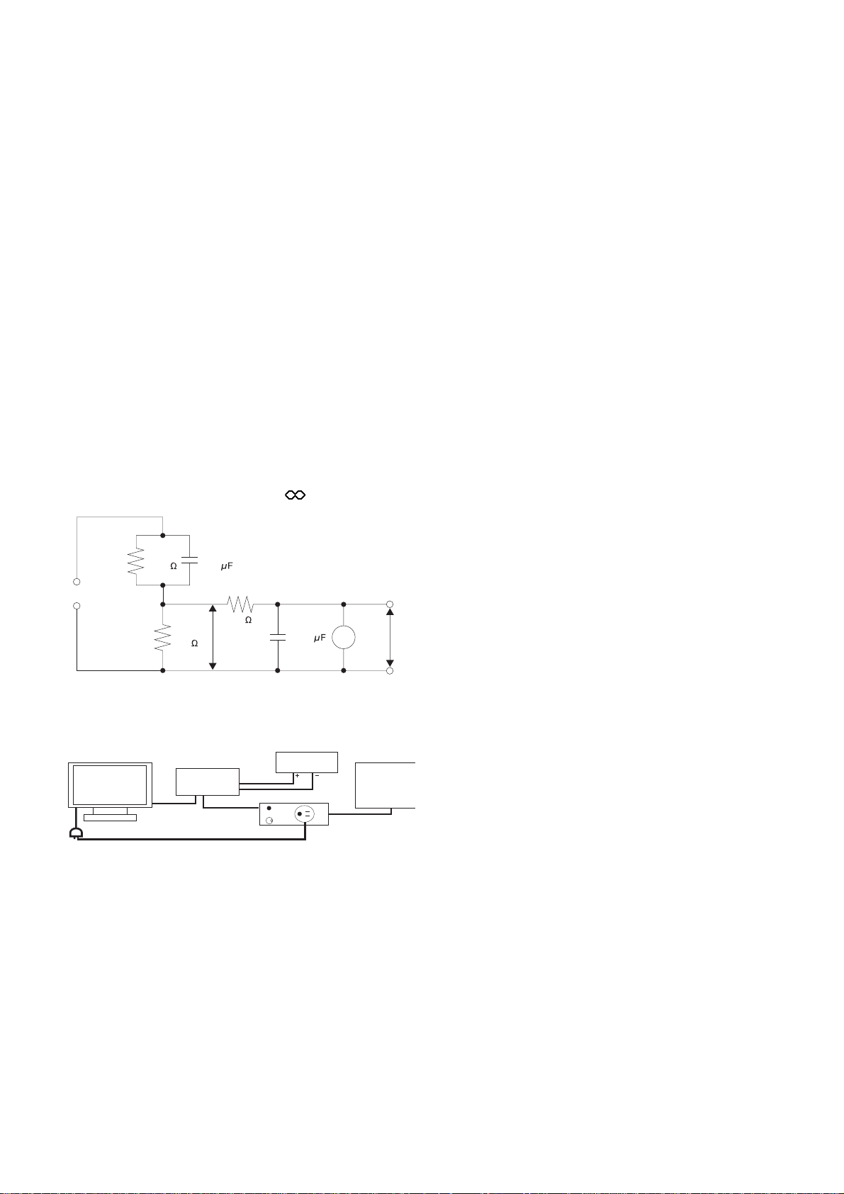
1.1.1. Leakage Current Cold Check
1. Unplug the AC cord and connect a jumper between the
two prongs on the plug.
2. Measure the resistance value, with an ohmmeter,
between the jumpered AC plug and each exposed metallic cabinet part on the equipment such as screwheads,
connectors, control shafts, etc. When the exposed metallic part has a return path to the chassis, the reading
above 4Mohm.
When the exposed metal does not have a return path to
the chassis, the reading must be .
R
ŵŦŴŵġűŰųŵ
=
s
1500 0.22
Figure 1. Leakage Current Test Tool
R
500
=
C
s
=
b
10k
)
U
(V
1
0.022
V
1.1.2. Leakage Current Check (See Figure
1 and Figure 2)
1. Plug the AC cord directly into the AC outlet. Do not us e
an isolation transformer for this check.
2. Make a leakage current test loop as shown in Figure 1.
3. The method of connecting leakage current test loop is
shown in Figure 2.
4. The measure value of U1(V) should be less than 35Vp
and U2(V) should be less than 0.35Vp.
)
U
(V
2
TH-32/37LRT12
leakage current
The GND of test ports
AC IN
test tool
AC N
Figure 2.
U1, U2
N
fix port
LN
SW
oscilloscope
leakage current outlet
AC POWER
SOURCE
3

TH-32LRT12U/M/A-B * TH-37LRT12U/M/A
2Warning
2.1. Prevention of Electrostatic Discharge (ESD) to Electrostatically
Sensitive (ES) Devices
Some semiconductor (solid state) devices can be damaged easily by static electricity. Such components commonly are called Electrostatically Sensitive (ES) Devices. Examples of typical ES devices are integrated circuits and some field-effect transistors and
semiconductor “chip” components. The following techniques should be used to help reduce the incidence of component damage
caused by electrostatic discharge (ESD).
1. Immediately before handling any semiconductor component or semiconductor-equipped assembly, drain off any ESD on your
body by touching a known earth ground. Alternatively, obtain and wear a commercially available discharging ESD wrist strap,
which should be removed for potential shock reasons prior to applying power to the unit under test.
2. After removing an electrical assembly equipped with ES devices, place the assembly on a conductive surface su ch as aluminum foil, to prevent electrostatic charge buildup or exposure of the assembly.
3. Use only a grounded-tip soldering iron to solder or unsolder ES devices.
4. Use only an anti-static solder removal device. Some solder removal devices not classified as “anti-static (ESD protected)” can
generate electrical charge sufficient to damage ES devices.
5. Do not use freon-propelled chemicals. These can generate electrical charges sufficient to damage ES devices.
6. Do not remove a replacement ES device from its protective package until immediately before you are ready to install it. (Most
replacement ES devices are packaged with leads electrically shorted together by conductive foam, aluminum foil or comparable conductive material).
7. Immediately before removing the protective material from the leads of a replacement ES device, touch the protective material
to the chassis or circuit assembly into which the device will be installed.
Caution
Be sure no power is applied to the chassis or circuit, and observe all other safety precautions.
8. Minimize bodily motions when handling unpackaged replacement ES devices. (Otherwise ham less motion such as the brushing together of your clothes fabric or the lifting of your foot from a carpeted floor can generate static electricity (ESD) sufficient
to damage an ES device).
4

TH-32LRT12U/M/A-B * TH-37LRT12U/M/A
2.2. About lead free solder (PbF)
Note: Lead is listed as (Pb) in the periodic table of elements.
In the information below, Pb will refer to Lead solder, and PbF will refer to Lead Free Solder.
The Lead Free Solder used in our manufacturing proc ess and discussed below is (Sn+Ag+Cu).
That is Tin (Sn), Silver (Ag) and Copper (Cu) although other types are available.
This model uses Pb Free solder in it’s manufacture due to environmental conservation issues. For service and repair work, we’d
suggest the use of Pb free solder as well, although Pb solder may be used.
PCBs manufactured using lead free solder will have the PbF within a leaf Symbol PbF stamped on the back of PCB.
Caution
• Pb free solder has a higher melting point than st andard solder . Typically the melting point is 50 ~ 70 °F (30~40 °C) higher. Please
use a high temperature soldering iron and set it to 700 ± 20 °F (370 ± 10 °C).
• Pb free solder will tend to splash when heated too high (about 1100 °F or 600 °C).
If you must use Pb solder, please completely remove all of the Pb free solder on the pins or solder area before applying Pb sol der. If this is not practical, be sure to heat the Pb free solder until it melts, before applying Pb solder.
• After applying PbF solder to double layered boards, please check the component side for excess solder which may flow onto the
opposite side. (see figure below)
Suggested Pb free solder
There are several kinds of Pb free solder available for purchase. This product uses Sn+Ag+Cu (tin, silver, copper) solder. However, Sn+Cu (tin, copper), Sn+Zn+Bi (tin, zinc, bismuth) solder can also be used.
5
TH-32LRT12U/M/A-B * TH-37LRT12U/M/A
3 Service Navigation
3.1. Important Notice
3.1.1. MANUFACTURING ID NO.
This service manual is for the MANUFACTURING ID NO. indicated in the label at side and the model name plate of the unit.
Label at side
Model Name Plate
3.2. Different P.C.B.
TH-32LRT12U/M/A TH-32LRT12U/M/A-B
TNM4CD0819FA TNM4CD0819FD MAIN BOARD only change soft
TNM4CD0822F TNM4CD0821F POWER BOARD
TNM4CD0906F IR
TNM4CD0809F AV3
TNM4CD0810F KEY
TNM4CD0820F RS232
Parts No. Parts name & Description Remarks
6
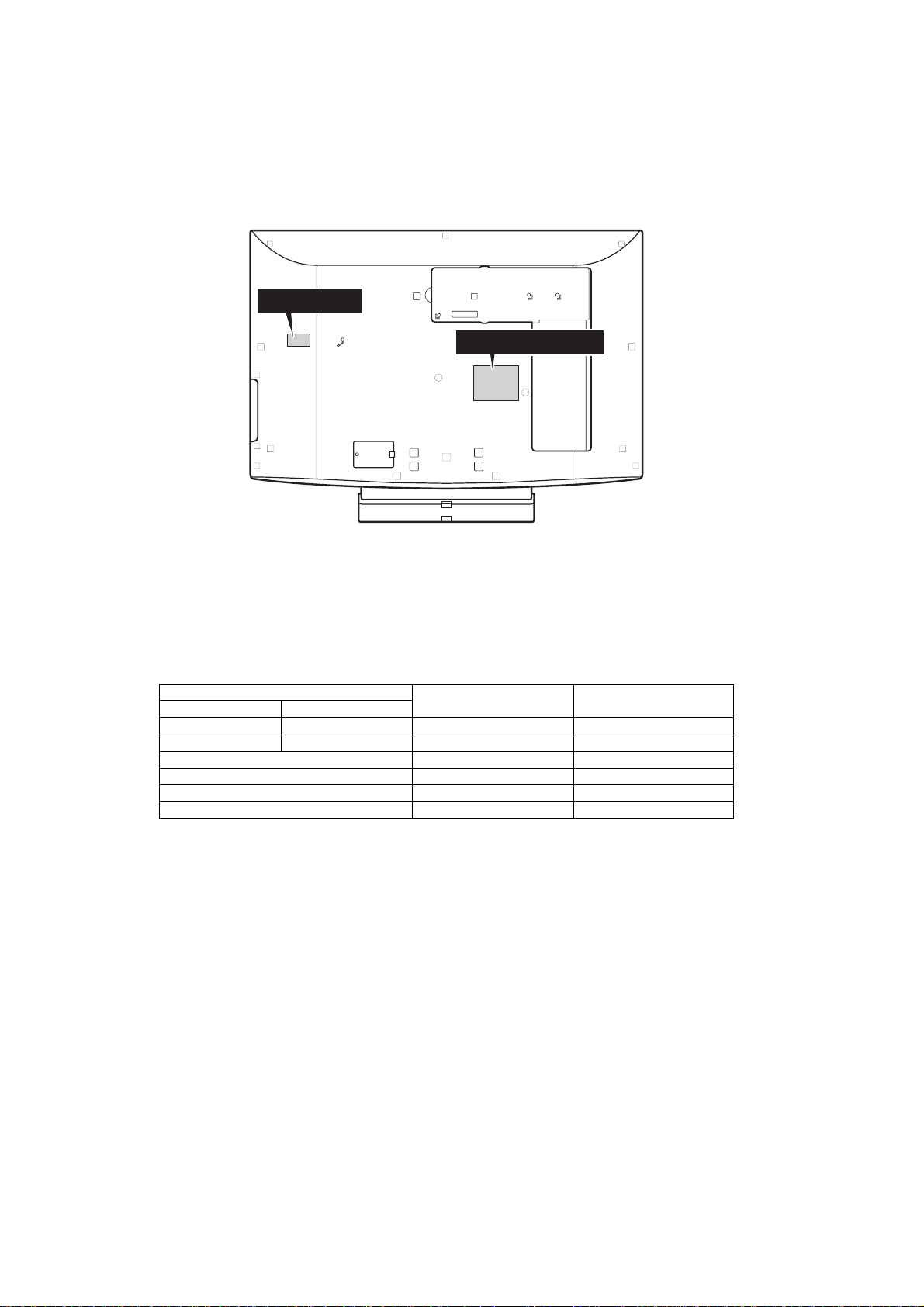
3.3. Service Hint
TH-32LRT12 U/M/A-B
TH-32LRT12U/M/A-B * TH-37LRT12U/M/A
Remove the Rear Cover
Back Cover
AC Cord
Pedestal Assy
1. Remove: 15 screws ( ) XTN4+15JFZ
3 screws ( ) XTB4+10FFZ
1 screw ( ) THT4CM010K
4 screws ( ) XYN4+F11FZ
2. Remove Pedestal Assy
3. Remove AC Cord and Back Cover
KEY
SP
POWER
BOARD
AV3
MAIN
BOARD
RS232
SP
IR
7
TH-32LRT12U/M/A-B * TH-37LRT12U/M/A
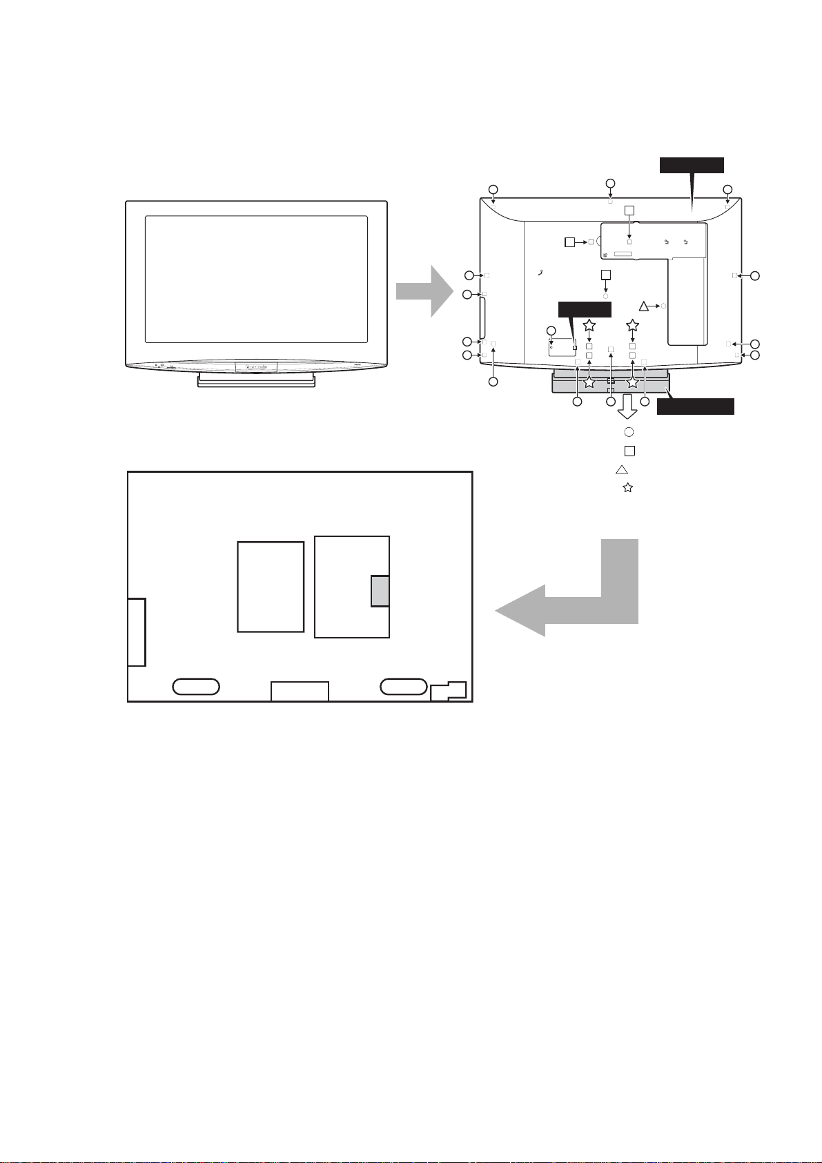
3.4. Service Hint
TH-37LRT12 U/M/A
Remove the Rear Cover
Back Cover
AC Cord
1. Remove: 14 screws ( ) XTB4+15JFZ
2 screws ( ) XYN4+F10FZ
1 screw ( ) THT4CM010K
2. Remove AC Cord and Back Cover
SP
POWER
BOARD
AV3+SW
Board Name Function
MAIN BOARD Sync Processor, Audio Processor,
POWER BOARD Power Supply Unit
AV3+SW AV3+KEY Switch
RS232 RS-232 Input terminal
MAIN
BOARD
IR Remote Switch, LED-G, R, Power Switch
RS232
SP
Speaker Out Amplifier, Slot Interface
(Audio / Video / Sync Input Switch)
IR
8

3.5. Applicable signals
Applicable input signals for Mini D-sub 15P
Signal name +RUL]RQWDOIUHTXHQF\
1 640 x 480 @ 60 Hz 31.47 59.94 25.18
2 640 x 480 @ 72 Hz 37.86 72.81 31.5
3 640 x 480 @ 75 Hz 37.50 75.00 31.5
4 800 x 600 @ 56 Hz 35.16 56.25 36.0
5 800 x 600 @ 60 Hz 37.88 60.32 40.0
6 800 x 600 @ 72 Hz 48.08 72.19 50.0
7 800 x 600 @ 75 Hz 46.88 75.00 49.5
8 1024 x 768 @ 60 Hz 48.36 60.00 65.0
9 1024 x 768 @ 70 Hz 56.48 70.07 75.0
10 1024 x 768 @ 75 Hz 60.02 75.03 78.75
Applicable input signals for HDMI and YPbPr
HDMI Mode YPbPr Mode
Signal name Signal name
1
2 480p@60Hz 2 480p@60Hz
3 576i@50Hz 3 576i@50Hz
4 576p@50Hz 4 576p@50Hz
5 720p@50Hz 5 720p@50Hz
6 720p@60Hz 6 720p@60Hz
7 1080i@50Hz 7 1080i@50Hz
8 1080i@60Hz 8 1080i@60Hz
9 1080p@50Hz 9 1080p@50Hz
10 1080p@60Hz 10 1080p@60Hz
480i@60Hz 1 480i@60Hz
N+]
TH-32LRT12U/M/A-B * TH-37LRT12U/M/A
9HUWLFDOIUHTXHQF\
+]
'RWFORFNIUHTXHQF\
0+]
Note: Signals without the above specifications may not be displayed properly.
9

TH-32LRT12U/M/A-B * TH-37LRT12U/M/A
4 Specifications
4.1. TH-32LRT12U/M/A-B
Power Source 110 - 127 V AC 50/60 Hz (TH-32LRT12U-B)
220 - 240 V AC, 50/60 Hz (TH-32LRT12M/A-B)
Power Consumption
Power on 155 W
Stand-by condition 1.0 W (TH-32LRT12U-B)
1.5 W (TH32LRT12A/M-B)
Aspect Ratio 16:9
Screen size 27.5" (698 mm) (W) x 15.4" (392 mm) (H) x 31.5" (800 mm) (diagonal)
(No.of pixels) 1,049,088 (1,366 (W) x 768 (H)) [4,098 x 768 dots]
Operating condition
Temperature 32 °F - 104 °F (0 °C - 40 °C)
Humidity 20 % - 80 %
Connection terminals
PC IN 0,1,'68%3,1*9SS
%9SS
59SS
HD/VD: 1.0 - 5.0 Vp-p (high impedance)
AUDIO IN (M3 JACK) 0.5 Vrms
AV1-AV3 9,'(2,15&$3,1-$&.[9SS
S VIDEO IN (MINI DIN 4PIN x 3) Y:1.0 9SS&9SS
AUDIO IN (RCA PIN JACK x 3) 0.5 Vrms
YP
BPR
HDMI1 - HDMI3 TYPE A Connector x 3
AUDIO OUT RCA PIN JACK x 2 0.5 Vrms
SERIAL EXTERNAL CONTROL TERMINAL (D-SUB 9PIN) RS-232C COMPATIBLE
Dimensions (W × H × D)
Including pedestal 32.4'' (821 mm) x 23" (584 mm) x 9.3" (236 mm)
Display Set only 32.4" (821 mm) x 21.3" (539 mm) x 4.2" (106 mm)
Mass (weight)
Including pedestal approx. 36.4 lbs
Display Set only approx. 30.9 lbs
Sound
Audio Output 20W [10 W + 10 W] (10 % THD)
Y (RCA PIN JACK x 1) 9SS
P
5&$3,1-$&.[9SS
B/PR
AUDIO IN (RCA PIN JACK x 1) 0.5 Vrms
Note: Design and specifications are subject to change without notice. Mass and dimensions shown are approximate.
10

TH-32LRT12U/M/A-B * TH-37LRT12U/M/A
4.2. TH-37LRT12U/M/A
Power Source 110 - 127 V AC 50/60 Hz (TH-37LRT12U)
220 - 240 V AC, 50/60 Hz (TH-37LRT12A/M)
Power Consumption
Power on 190 W
Stand-by condition 1.0 W (TH-37LRT12U)
1.5 W (TH-37LRT12A/M)
Aspect Ratio 16:9
Screen size 32.2" (819 mm) (W) x 18.1" (460 mm) (H) x 37.0" (940 mm) (diagonal)
(No.of pixels) 1,049,088 (1,366 (W) x 768 (H)) [4,098 x 768 dots]
Operating condition
Temperature 32 °F - 104 °F (0 °C - 40 °C)
Humidity 20 % - 80 %
Connection terminals
PC IN 0,1,'68%3,1*9SS
%9SS
59SS
HD/VD: 1.0 - 5.0 Vp-p (high impedance)
AUDIO IN (M3 JACK) 0.5 Vrms
AV1-AV3 9,'(2,15&$3,1-$&.[9SS
S VIDEO IN (MINI DIN 4PIN x 3) Y:1.0 9SS&9SS
AUDIO IN (RCA PIN JACK x 3) 0.5 Vrms
YP
BPR
HDMI1 - HDMI3 TYPE A Connector x 3
AUDIO OUT RCA PIN JACK x 2 0.5 Vrms
SERIAL EXTERNAL CONTROL TERMINAL (D-SUB 9PIN) RS-232C COMPATIBLE
Dimensions (W × H × D)
Including pedestal 37.4'' (949 mm) x 25.6" (650 mm) x 12.1" (307 mm)
Display Set only 37.4" (949 mm) x 24" (608 mm) x 4.1" (104 mm)
Mass (weight)
Including pedestal approx. 47.4 lbs
Display Set only approx. 39.7 lbs
Sound
Audio Output 20W [10 W + 10 W] (10 % THD)
Note: Design and specifications are subject to change without notice. Mass and dimensions shown are approximate.
Y (RCA PIN JACK x 1) 9SS
P
5&$3,1-$&.[9SS
B/PR
AUDIO IN (RCA PIN JACK x 1) 0.5 Vrms
11
TH-32LRT12U/M/A-B * TH-37LRT12U/M/A
5 Factory Mode
5.1. How to enter into Factory Mode
Press and hold [VOL+] button and [VOL-] button of the main unit more than 3 seconds.
Main item
Sub item
Software Version
SPV7100
OA
SPV7100 PICTURE
R OFFSET
G OFFSET
B OFFSET
R GAIN
G GAIN
B GAIN
516 CONTRAST
516 BRIGHTNESS
516 SATURATION
516 HUE
H PEAK BP GAIN
H PEAK HP GAIN
H PEAK LP GAIN
H PEAK CORING
H PEAK CLIP
V PEAK GAIN
V PEAK CLIP
NR
PHASE
NTSCM
TH-32LRTB V3.0 090923
WTCodeVersion V3.0
FACTORY MENU
OD OE OF
0x7A
0x7A
0x7A
0x80
0x80
0x80
0x85
0x1A
0x90
0x00
0x02
0x0D
0x04
0x00
0x0F
0x18
0x10
OFF
0x00
056A0220
5.1.1. Key command
[ ] button...Main items Selection in forward direction and value of sub items change.
[ ] button...Main items Selection in reverse direction and value of sub items change.
[ ] button...Sub items Selection in forward direction
[ ] button...Sub items Selection in reverse direction
[OK] button...Back to main items selection from sub items selection
5.1.2. Contents of adjustment mode
• Value is shown as a hexadecimal number.
• Preset value differs depending on mode
• After entering the adjustment mode, take note of the value in each item before starting adjustment.
Main item Sub item Adjustment
R OFFSET Set R Brightness
G OFFSET Set G Brightness
B OFFSET Set B Brightness
R GAIN R white-Balance
G GAIN G white-Balance
B GAIN B white-Balance
516 CONTRAST Set_Decoder_Contrast
516 BRIGHTNESS Set_Decoder_Brightness
0A
(SPV7100 PICTURE)
516 SATURATION Set_Decoder_Saturation
516 HUE Set_Decoder_Hue
H PEAK BP GAIN Static gain after BP for Peaking
H PEAK HP GAIN Static gain after HP for Peaking
H PEAK LP GAIN Static gain after LP for Peaking
H PEAK CORING Coring threshold for Peaking
H PEAK CLIP The adjusted threshold for Peaking
V PEAK GAIN Static gain for Vertical Edge Enhancement
V PEAK CLIP Adjusted threshold for Vertical Edge Enhancement
NR Noise reduction
PHASE PLL clock phase
12
TH-32LRT12U/M/A-B * TH-37LRT12U/M/A
Main item Sub item Adjustment
ADC PR GAIN R channel gain Register
ADC Y GAIN G channel gain Register
0B
(SPV 7100 ADC)
0D
(SPV 7100 AUDIO)
0E
(SPV 7100 SCALER)
0F
(SPV 7100 SYSTEM)
ADC PB GAIN B channel gain Register
ADC PR OFFSET R channel OFFSET Register
ADC Y OFFSET G channel OFFSET Register
ADC PB OFFSET B channel OFFSET Register
ADC Auto White AutoWhite
100HZ EQ MAIN Equalizer Band 1 Control (100 Hz)
300HZ EQ MAIN Equalizer Band 2 Control (300 Hz)
1000HZ EQ MAIN Equalizer Band 3 Control (1000 Hz)
3000HZ EQ MAIN Equalizer Band 4 Control (3000 Hz)
8000HZ EQ MAIN Equalizer Band 5 Control (8000 Hz)
DEC LEV LEV_ADJ_DEM_REG(level adjust)Stereo RF MODE
MONO LEV LEV_ADJ_DEM_REG(level adjust)MONO RF MODE
NIC LEV LEV_ADJ_DEM_REG(extra gain for NICAM) RF MODE
SAP LEV LEV_ADJ_DEM_REG(level adjust)SAP RF MODE
ADC LEV LEV_ADJ_DEM_REG(level adjust)AV Ypbpr PC MODE
DIGIN LEV LEV_ADJ_DEM_REG(level adjust)HDMI MODE
LOUD Set_Loudness_On_Off
LOUD LEV Set_LOUD_LEV
LOUD FIL Set_LOUD_LEV (500Hz or 1000Hz)filter
SOUND AI AVL Reference Level
AUDIO OUT LEV Set_AUDIO_OUT_LEV
H START Set_H_Start_Position
V START Set_V_Start_Position
H OVERSCAN Set_H_Overscan
V OVERSCAN Set_V_Overscan
OPTION Set_H_V_Overscan_Reference_Point
POLLING STATE Set_Polling_State
EEPROM RESET Reset_EEPROM
BURN IN BurnIn _Set
UART ON DSUB Set_UART_State
OpenDebug OpenDebugInformation
Baud Rate Set_BaudRate
SPREAD SPECTRUM Set_Spread_Spectrum
DPLLMD-L Display PLL modulation setting
DPLLCU Display PLL charge pump current setting
BANK Set_Bank
REGISTER Set_Register
READ Register_Read
WRITE Register_Write
VALUE Set_Register_Value
5.2. How to exit
Switch off the power with the [POWER] button on the main unit or the [POWER] button on the remote control or press and hold
[VOL+] and [VOL-] buttons on the main unit at the same time.
13
TH-32LRT12U/M/A-B * TH-37LRT12U/M/A
1
2
1
6 Operating Instructions
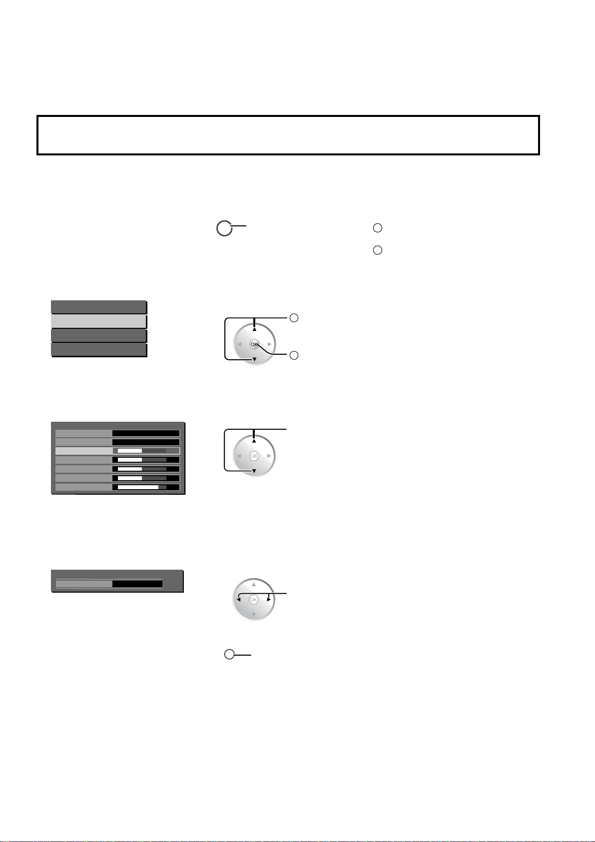
6.1. On-Screen Menu Display
2Q6FUHHQ0HQX'LVSOD\
V arious menus allow you to make settings for the picture, sound, and other functions so that you can enjoy watching Display
best suited for you.
5HPRWH&RQWURO Unit
'LVSOD\WKHPHQXVFUHHQ
1
Select the menu.
2
Main Menu
Picture Menu
Sound Menu
Setup Menu
Select the item.
3
Picture Menu
Picture Mode
Standard
Contrast
Brightness
Color
Tint
Sharpness
User
Off
MENU
Press the menu button.
Select
Action
2
Select
32
32
32
00
12
Press the MENU button.
Press the CH buttons to select the
menu.
Press the MENU button.
Press the CH < or > buttons to select
the item.
(Example: Picture Menu)
$GMXVWRUVHOHFW
4
Contrast
([LWWKHPHQX
5
Press the VOL + or – buttons.
32
RETURN
Press several times until you exit
the menu.
Press to return to the
previous menu.
Adjust
Press the INPUT button several times
until you exit the menu.
14
TH-32LRT12U/M/A-B * TH-37LRT12U/M/A
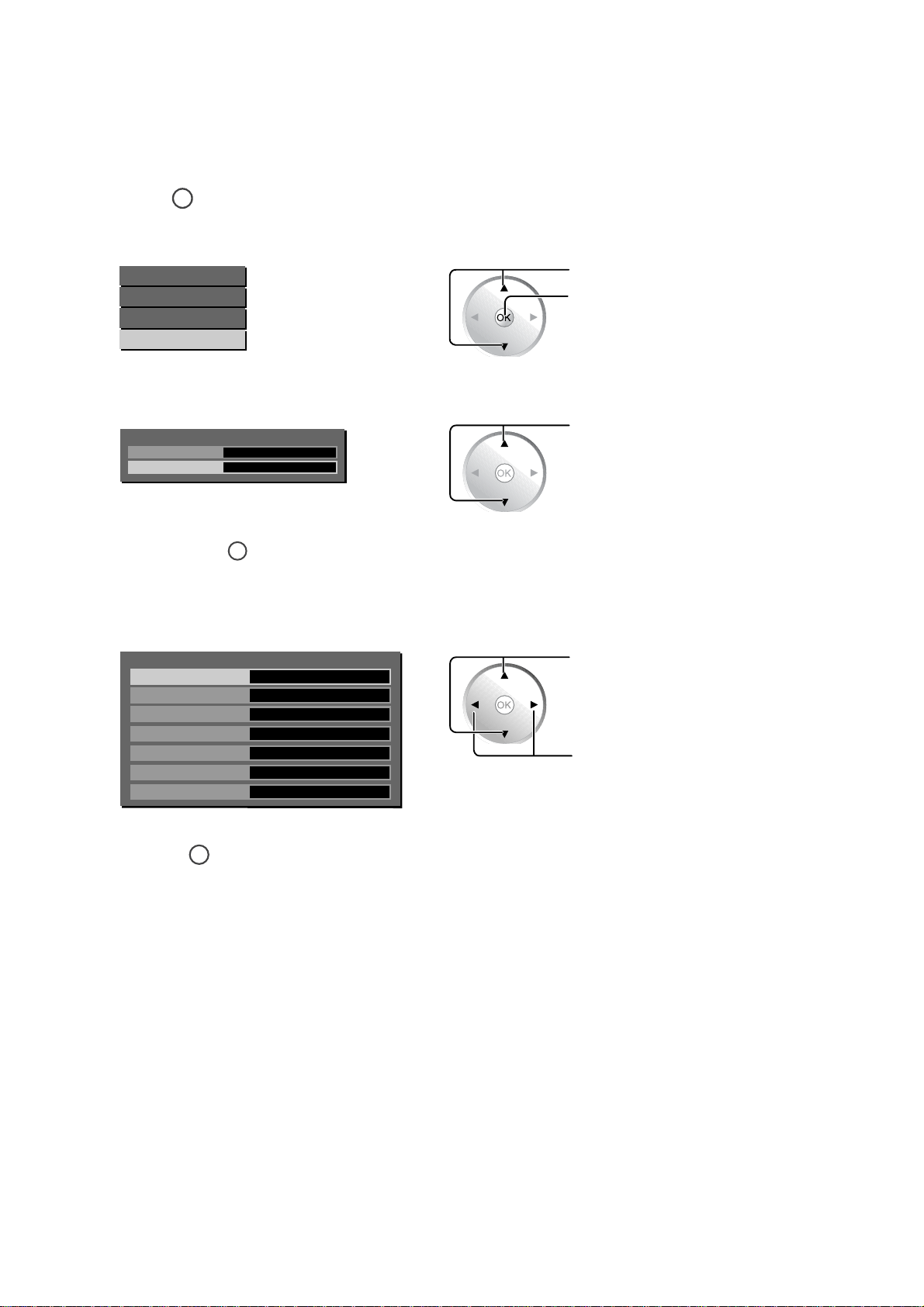
6.2. Hotel Mode
The Hotel Mode is a special function which allows users to configure settings to suit certain locations or applications.
6.2.1. Hotel mode setup
Press
1
Select Setup Menu.
2
Select Movie Mode.
3
Press and hold
4
Select the item and set desired settings.
5
MENU
Main Menu
Picture Menu
Sound Menu
Setup Menu
Setup Menu
Language
Movie Mode
to display the menu screen.
English
On
MUTE
for more than 3 seconds.
Press to select the Setup menu.
Press to enter menu.
Press to select the item.
6
Setup Menu
Initial Input
Onscreen Display
Initial VOL Level
Maximum VOL Level
Input Lock
Button Lock
Remocon User Level
Press
RETURN
Off
On
Off
Off
Off
Menu
Off
repeatedly to exit the menu.
Press to select the item.
Press to adjust settings.
15
TH-32LRT12U/M/A-B * TH-37LRT12U/M/A
6.2.2. Hotel mode menu list
Item Details
Off
RF AV1 AV2 AV3 YPbPr HDMI1 HDMI2 HDMI3 PC
Adjusts the input signal when the unit is turned on.
Initial Input
Onscreen Display
Initial VOL Level
Maximum VOL
Level
Off: The input signal when the power was last turned off is set.
Note:
This menu is available only when "Input Lock" is "Off".
RF mode is available only when Pal Tuner is connected.
Off: Onscreen information is not displayed.
On: Onscreen information is displayed, such as:
•
Power on display
•
Input signal switch display
•
No signal display
•
Mute and the remaining time of off-timer
On 1: Onscreen information is displayed, except some RS-232C communication information is not
displayed.
Used to set the volume level at power-on.
Off: The volume is set to the same level as when the power was last turned off.
0 to 63: The volume is set to the selected level.
Note:
It is not possible to select an Initial VOL Level setting which is higher than the Maximum VOL Level setting.
Used to set the volume level so that it will not exced the maximum setting.
Off: No restrictions are placed on the volume level.
0 to 63: The volume is restricted to the selected level.
Note:
It is not possible to select a Maximum VOL Level setting which is lower than the Initial VOL Level setting.
Input Lock
Button Lock
Remocon User
Level
Off
RF AV1 AV2 AV3 YPbPr HDMI1 HDMI2 HDMI3 PC
Locks the input switch operation.
Off: Input switch can be used.
Note:
RF mode is available only when Pal Tuner is connected.
Used to restrict the operation of the buttons on the main unit.
Off: All the buttons on main unit can be used.
Menu: Locks the Menu button on the main unit.
On: Locks all the buttons on the main unit except the Power button.
Off
Off: You can use all of the buttons on the remote control.
User1:You can only use
User2:You can only use
User1 User2 User3
MUTE
INPUT
POWER
,
, ,
,
POWER
button on the remote control.
VOL
buttons on the remote control.
User3:Locks all the buttons on remote control.
Note: Hotel Mode menu may not be accessible when you select “User2” or “User3”. When this happens,
press the VOL- on the display and the OK button on the remote control at the same time. The message
“Are you sure to out the mode?” will appear, select “Yes”.
16

7 Troubleshooting Guide
7.1. No Power
NO POWER
TH-32LRT12U/M/A-B * TH-37LRT12U/M/A
7.2. No Picture
Check
Power board
NG
Check
Fuse F1
Conn ec tor CN3ΕCN4ΕCN7
NO PICTURE
Check
OSD
OK
NG
Conn ec tor J7ΕCN10
Check Main board
Conn ec tor J5ΕCN10
Check
OK
Chec k M ai n bo a r d
Location CN1(Flash IC)
OK
Check
Location U14(SPV7100P)
17

TH-32LRT12U/M/A-B * TH-37LRT12U/M/A
8 Disassembly and
Assembly Instructions
Caution:
Exchange printed circuit board after confirm parts number.
Parts name & Descrption Parts No.
MAIN PCB TNM4CD0819FD
POWER PCB TNM4CD0821F
8.1. TH-32LRT12U/M/A-B Instructions
• To disassemble P.C.B., wait for 1 minute after power was off
for discharge from electrolysis capacitors.
• , , , , , and marks indicate screw positions.
8.1.1. Removal of Pedestal Assy and
Back Cover
1. Remove screws (x15 , x3 , x1 , x4 ) and then
remove the Pedestal Assy.
Back Cover
2. Remove 4 screws ( ), disconnect the connectors and
then remove the EMI Case.
EMI Case
3. Disconnect the connectors including Speaker (R),
speaker (L), CON33, CON42, CON34 CN1 (panel
inverter), CN1 (panel driver), and remove the 13 foil.
CN1
AC Cord
Pedestal Assy
2. Remove the AC cord from the slot.
3. Remove the Back Cover.
8.1.2 Removal of EMI Case Unit
1. Remove screws (x3 , x4 , x3 ) and then remove the
AV co ve r.
AV Cover
CON34
CN1
CON33
CON42
Speaker (L)Speaker (R)
18
TH-32LRT12U/M/A-B * TH-37LRT12U/M/A
ON1C
8.1.3 Removal of the Main PCB,
Power PCB, and RS232 PCB
1. Turn the EMI case over and then remove 8 screws.
• Disconnect the connectors (CON7, CON1, CON34,
CON8, CON12, CON11, J5, J7, J8, CON10).
• Unfasten the wire clip
• Disconnect the connectors CON1 of the RS232 board.
• Disconnect the connectors including CN3, CN4, CN7,
and CN1 (AC CORD).
Main PCB
¿, ¡, ¬.
Power PCB
8.1.5 Removal of IR PCB and AV3
PCB
1. Remove 2 screws ( ) and then remove the IR PCB.
2. Remove 2 screws ( ) and then remove the AV3 PCB.
IR PCBAV3 PCB
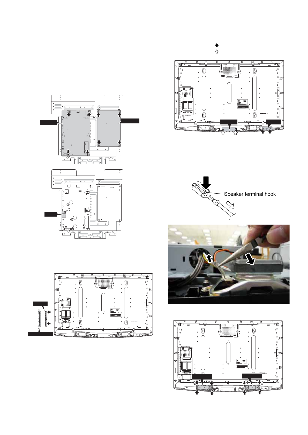
8.1.6 Removal of Speaker (L, R)
1. Connected terminal hook is pushed, and the speaker lead
in 4 places is pulled out.
2. To safely remove speaker, see picture below:
CN3
RS232
CON13
1
CON34
CON8
CON1
2
3
CON7
CON12
CON11
J5
J8
J7
CON10
CN1
CN4
CN7
8.1.4 Removal of Operation Button
1. Remove the Operation Button.
2. Remove 2 screws and then remove the key PCB.
Key PCB
OPeration Button
3. Remove 8 screws and then remove the Speaker (L, R).
Speaker (R)
Speaker (L)
19

TH-32LRT12U/M/A-B * TH-37LRT12U/M/A
8.1.7 Removal of LCD Panel and
Cabinet
1. Remove 11 screws and then remove the Panel Fixed.
Panel Fixed Panel Fixed
Panel Fixed
Panel Fixed
2. Remove the LCD Panel from the Cabinet.
Panel Fixed
Panel Fixed
Panel Fixed
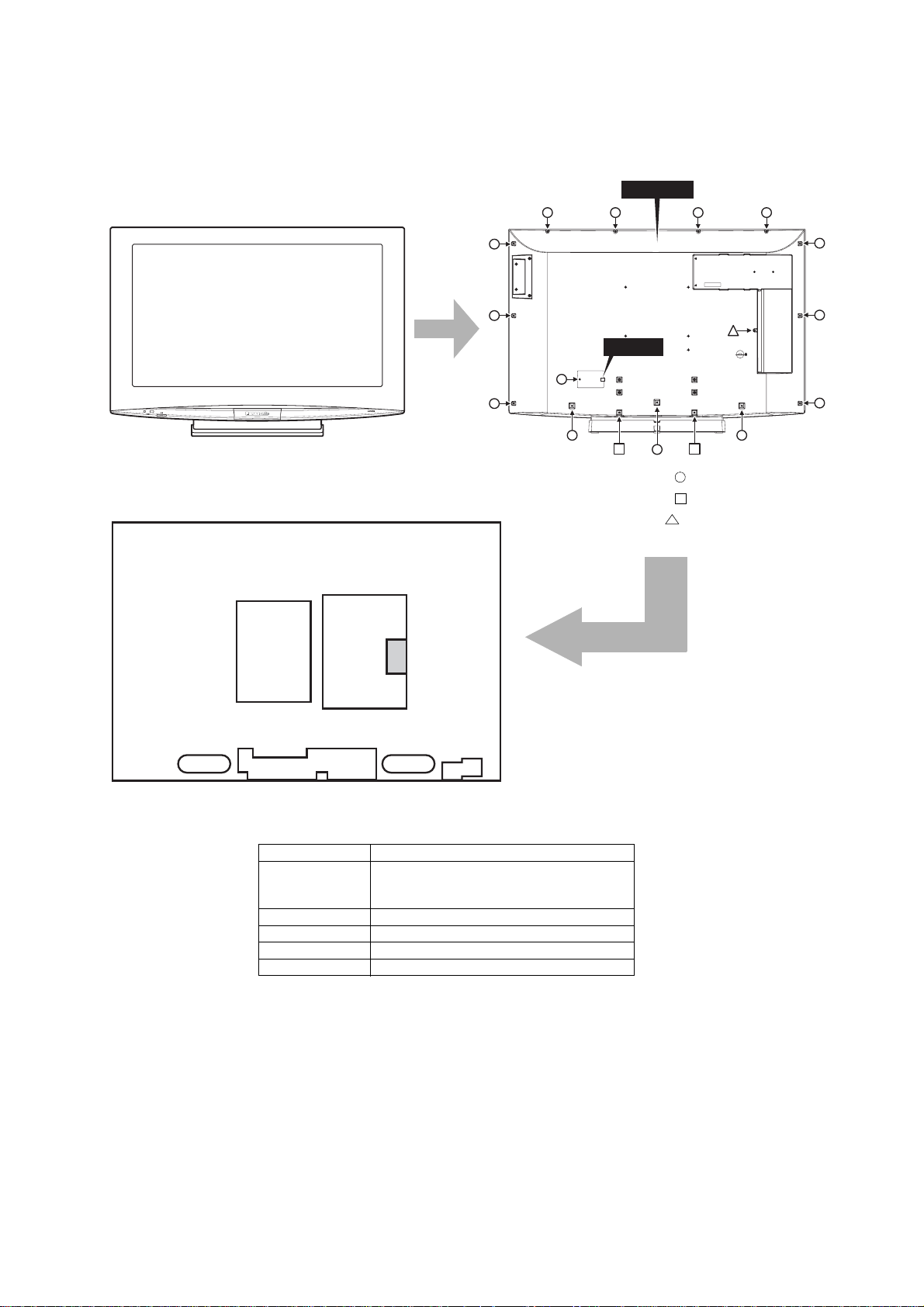
8.2. TH-37LRT12U/M/A Instructions
• To disassemble P.C.B., wait for 1 minute after power was off
for discharge from electrolysis capacitors.
• , , , , , and marks indicate screw positions.
8.2.1 Removal of Back Cover
1. Remove screws (x14 , x2 , x1 ) and then remove
the Back Cover.
2. Remove the AC cord from the slot.
Back Cover
AC Cord
8.2.2 Removal of Pedestal Assy
1. Remove 4 screws ( ) and then remove the Pedestal
Assy.
Pedestal Assy
8.2.3 Removal of EMI Case and Wall
Mount Holder
1. Remove 9 screws ( ) and then remove the EMI Case.
2. Remove 4 screws ( ) and then remove the Wall Mount
Holder.
Wall Mount Holder
EMI CASE
Wall Mount Holder
20

TH-32LRT12U/M/A-B * TH-37LRT12U/M/A
8.2.4 Removal of Main PCB, Power
PCB, and RS232 PCB
1. Remove screws (x4 ) of the Power PCB.
2. Remove screws (x5 , x3 , x3 , x4
PCB.
3. Disconnect the connectors CON1 of the RS232 PCB.
Power PCB
Main PCB
4. Disconnect the connectors (CON7, CON1, CON34,
CON8, CON12, CON11, CON10, J5, J8, J7).
• Disconnect the connectors (CON7, CON1, CON34,
CON42, CON8, CON12, CON11, CON10, J5, J8, J7)
and then remove the Main PCB.
• Unscrew
¿, ¡, ¬.
• Disconnect the connectors (CN3, CN4, CN7, CN1-AC
CORD) and then remove the Power PCB.
I) of the Main
8.2.5 Removal of Power SW PCB and
Operation PCB
1. Remove 4 screws ( ) and then remove the Power SW
PCB and Operation PCB.
Power SW PCBOperation PCB
8.2.6 Removal of Speaker (L, R)
1. Connected terminal hook is pushed, and the speaker lead
in 4 places is pulled out.
2. To safely remove speaker, see picture below:
CN1
Speaker (R)
CN7
CON34
CN4
CN1
CON33
CN1
CN3
CON10
9
CON7
J5
J8
SCREW
CON34
J7
CON12
CON11
Speaker (L)
CON1
8
CON1
CON8
7
CON42
3. Remove 8 screws and then remove the Speaker (L, R).
21
Speaker (L)Speaker (R)

TH-32LRT12U/M/A-B * TH-37LRT12U/M/A
8.2.7 Removal of LCD Panel and
Cabinet
1. Remove screws (x5 , x4 ) and then remove the
Chassis Frame.
Chassis Frame
2. Remove screws (x8 , x4 ) and then remove the Panel
Fixing.
Panel Fixing
Panel Fixing
Panel Fixing
Panel Fixing
3. Remove the LCD Panel from the Cabinet.
22
9 Adjustments and Upgrade
TH-32LRT12U/M/A-B * TH-37LRT12U/M/A
9.1. White Balance Adjustment
(TH-32LRT12U/M/A-B)
9.1.1. Test Condition
1. Press the "Factory Settings" button on the custom remote
or hold down the "Volume+ -" keys on the screen for 3
seconds to access the "Factory Mode".
2. Software Reset: Before screen warm-up, go to option
"0F" in factory mode and at "RESET" press the "Left" button on the remote.
3. Screen Burn-in: Go to option "OF" in factory mode and at
"BURN IN", press the "Left" button on the remote to
switch to "W" then exit factory mode. Allow to burn in for
"1 hour". After burn-in, enter factory mode and change
"BURN IN" to "OFF" before proceeding with White Balance Adjustment.
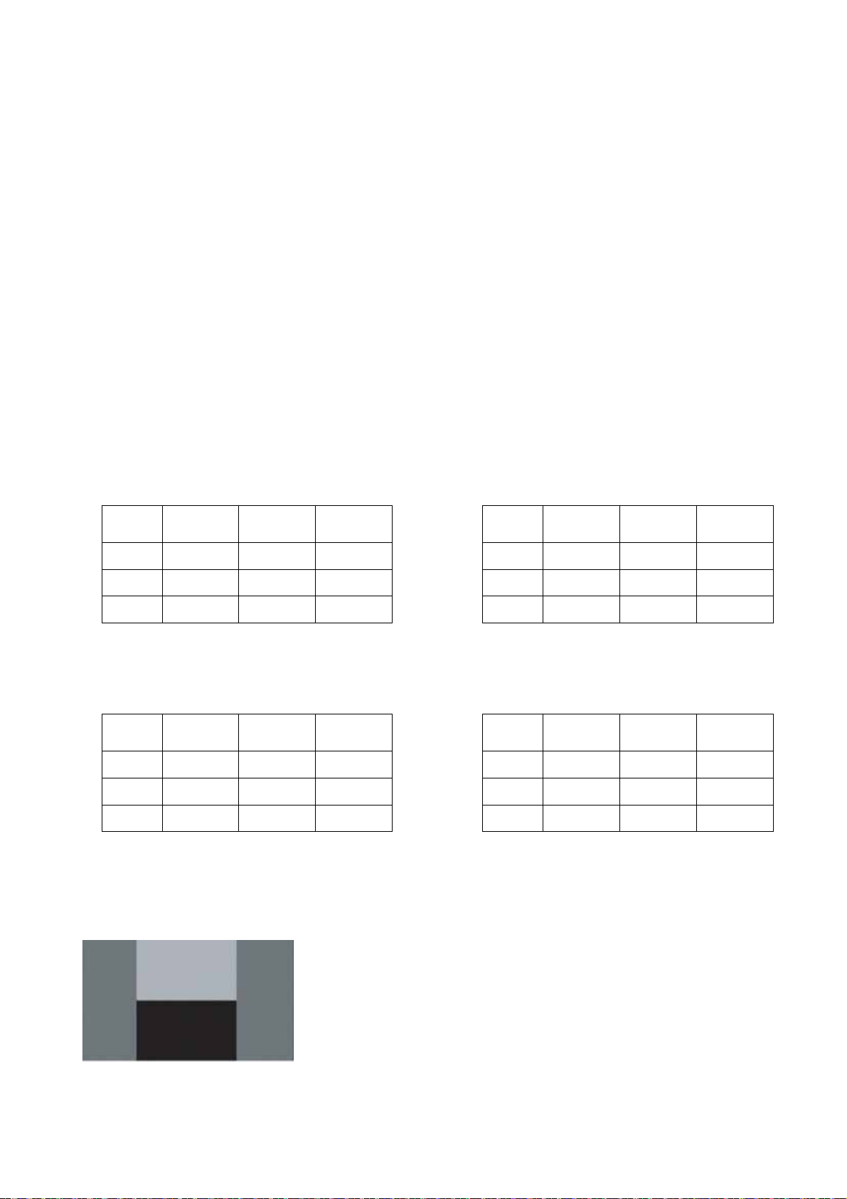
4. White Balance Adjustment:
Set TV to “AV1”; Input signal is H Pattern*.
9.1.2. Low Light Adjustment
1. In option "0A" under factory mode, use "R OFFSET " and
"B OFFSET" to set the hue and brightness.
x(cd/m
y(cd/m
Y(cd/m
Adjustment
(auto)
2
0.280±0.003 0.280±0.005 0.280±0.01
)
2
0.285±0.003 0.285±0.005 0.285±0.01
)
2
3±0.5 3±0.5 3±0.5
)
Adjustment
(manual)
Confirmation
9.2. White Balance Adjustment
(TH-37LRT12U/M/A)
9.2.1. Test Condition
1. Press the "Factory Settings" button on the custom remote
or hold down the "Volume+ -" keys on the screen for 3
seconds to access the "Factory Mode".
2. Software Reset: Before screen warm-up, go to option
"0F" in factory mode and at "RESET" press the "Left" button on the remote.
3. Screen Burn-in: Go to option "OF" in factory mode and at
"BURN IN", press the "Left" button on the remote to
switch to "W" then exit factory mode. Allow to burn in for
"1 hour". After burn-in, enter factory mode and change
"BURN IN" to "OFF" before proceeding with White Balance Adjustment.
4. White Balance Adjustment:
Set TV to “AV1”; Input signal is H Pattern*.
9.2.2. Low Light Adjustment
1. In option "0A" under factory mode, use "R OFFSET" and
"B OFFSET" to set the hue and brightness.
x(cd/m
y(cd/m
Y(cd/m
Adjustment
(auto)
2
0.280±0.003 0.280±0.005 0.280±0.01
)
2
0.285±0.003 0.285±0.005 0.285±0.01
)
2
3.5±0.5 3.5±0.5 3.5±0.5
)
Adjustment
(manual)
Confirmation
9.1.3. High Light Adjustment
1. In option "0A" under factory mode, use "R GAIN" and "B
GAIN" to set the hue and brightness.
x(cd/m
y(cd/m
Y(cd/m
Adjustment
(auto)
2
0.280±0.003 0.280±0.005 0.280±0.01
)
2
0.285±0.003 0.285±0.005 0.285±0.01
)
2
200±1.0 200±1.0 200±15.0
)
Adjustment
(manual)
Confirmation
* H Pattern:
9.2.3. High Light Adjustment
1. In option "0A" under factory mode, use "R GAIN" and "B
GAIN" to set the hue and brightness.
x(cd/m
y(cd/m
Y(cd/m
Adjustment
(auto)
2
0.280±0.003 0.280±0.005 0.280±0.01
)
2
0.285±0.003 0.285±0.005 0.285±0.01
)
2
200±1.0 200±1.0 200±15.0
)
Adjustment
(manual)
Confirmation
23
TH-32LRT12U/M/A-B * TH-37LRT12U/M/A
9.3. Software Upgrade
9.3.1. Main micon eeprom upgrade
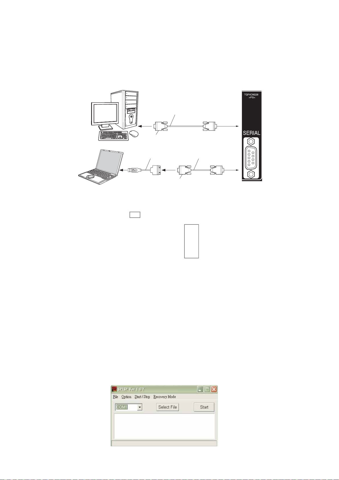
How to upgrade:
1. Turn on the display and enter into Factory mode.
2. Use an RS232 cable to connect the display with the computer. The way of connection is shown below:
3. When using a notebook computer for upgrade, use a USB to RS-232 adapter to connect the RS -232 cable to the notebook,
then connect the RS-232 cable to the display. (Connect the 9th pin of the RS-232 cable to the ground.)
RS-232 cable
USB to RS-232 adapter
4. Record 0A 6 groups of values as marked below:
SPV7100
OA
SPV7100 PICTURE
R OFFSET
G OFFSET
B OFFSET
R GAIN
G GAIN
B GAIN
516 CONTRAST
516 BRIGHTNESS
516 SATURATION
516 HUE
H PEAK BP GAIN
H PEAK HP GAIN
H PEAK LP GAIN
H PEAK CORING
H PEAK CLIP
V PEAK GAIN
V PEAK CLIP
NR
PHASE
NTSCM
TH-32LRTB V3.0 090923
WTCodeVersion V3.0
D-SUB 9 pin
D-SUB 9 pin
FACTORY MENU
OD OE OF
(female)
RS-232 cable
(female)
0x7A
0x7A
0x7A
0x80
0x80
0x80
0x85
0x1A
0x90
0x00
0x02
0x0D
0x04
0x00
0x0F
0x18
0x10
OFF
0x00
056A0220
4. Use a 9 pin D-SUB cable to connect the display with the computer.
5. Open ISP TOOL software on the computer.
6. Select the connected COM port of the computer in the drop-down list.
24

7. Select Option on the main bar, then change the setting values as below:
8. Click Select File to choose the upgrade file.
TH-32LRT12U/M/A-B * TH-37LRT12U/M/A
9. Click Start to begin upgrading.
10. When upgrade is completed, a window appears as shown below. Then unplug the display after at least 3 seconds.
25
 Loading...