

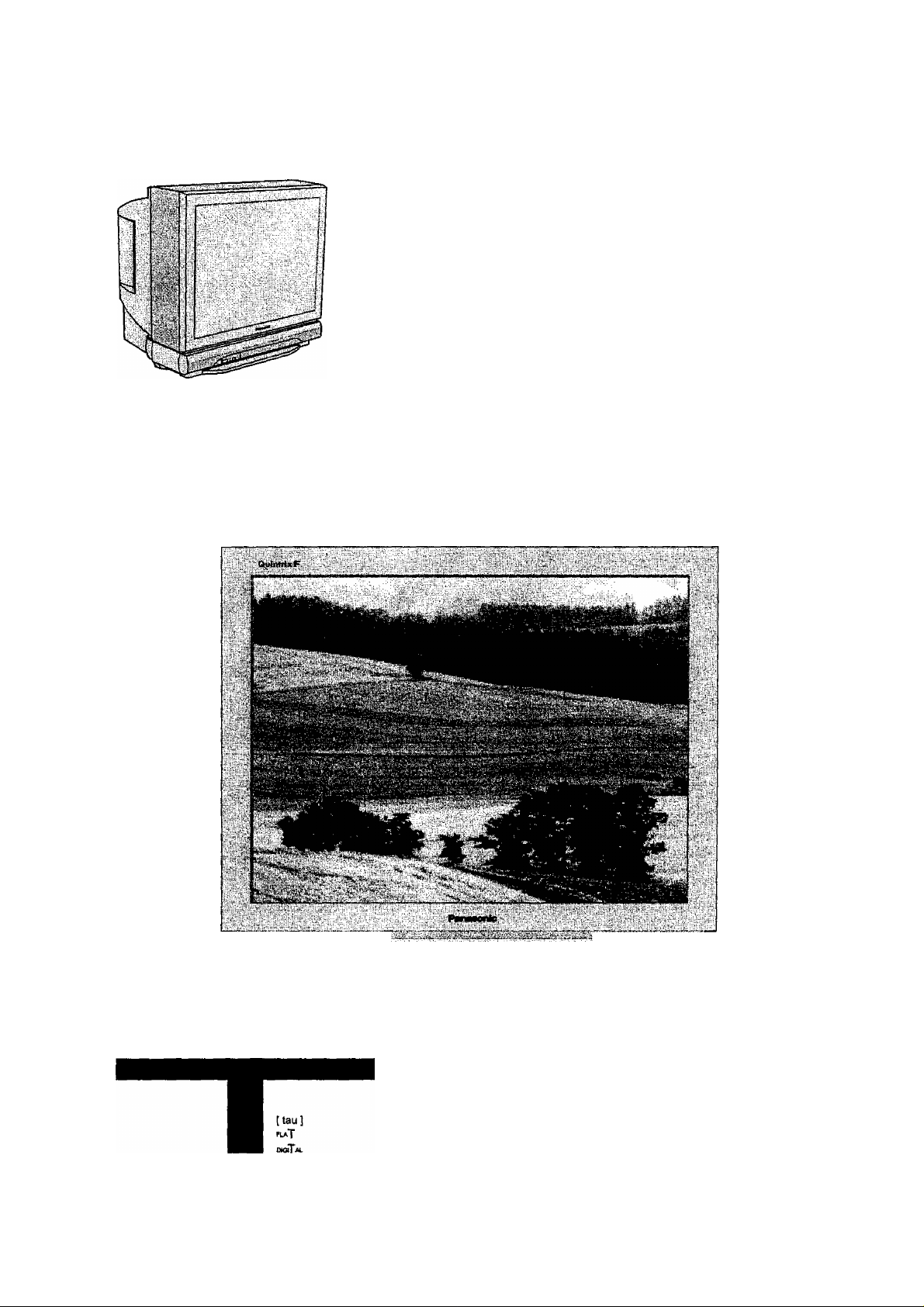
Panasonic TC-34P250X User Manual
Panasonic
I c^R'cr
fOQQ
QioaQ
Olio
GgO
Colour Television
Operating Instructions
ModeiNo TX-29P250X TC-29P250H
TX-68P250Z TC-34P250H
TX-80P250Z
This is a combined Operating Instruction manual for all the above
series of models.
Please read these instructions before opreting your set and
retain them for future reference,
TQB4G0909

Dear Panasonic Customer
Welcome to the Panasonic family of customers. We hope that you will
have many years of enjoyment from your new colour television set.
To obtain maximum benefit from your set, please read these Instructions
before making any adjustments, and retain them for future reference.
Retain your purchase receipt also, and note down the Model Number and
Serial Number of your set in the space provided on the rear cover of
these Instructions.
Table of Contents
Warnings and Cautions___________________________________________ 4
Before Operating This Set
How to Use This Manual
Battery Installation.................................................................................................................................................6
Connecting the Aerial cable to the RF In Terminal................................................................................................ 7
Connecting the Plug to the Wall outlet...................................................................................................................7
How to turn the Power On..................................................................................................................................... 7
Location of Controls
Remote Control......................................................................................................................................................8
Controls and Terminals on the TV................................
Connections ________________________________________________ 10H3
How to connect the "AVI, 2. 3 or 4" Input Terminals.............................................................................................10
How to connect the AV Monitor Output Terminals to other equipment.................................................................11
How to connect ttie DVD Input Terminals........................................................................................................... 11
How to connect the RGB Input Terminals...........................................................................................................12
Connecting Headphones.....................................................................................................................................13
......................................................................................................................................6
______________________________________________
_______________________________________
........
..................................................................................9
6"7
^
Table of Contents
General Operation
How to switch the power ON or OFF .
Programme Number Selection
Direct Programme Number Selection
Volume Adjustment
Mute Button
TV/AV Mode Selection
Recall Button..................................
SIR..................................................
Function selection
........................
....................................
...................
..........................
.......
Geomagnetic Correction
Using the On Screen Displays
Picture Menu
Sound Menu
Setup Menu
Tuning Menu
Channel Selection
Tuning Menu
Auto tune
Auto tune (via front panel)
Manual tune
Manual tune (via front panel)
........................
..........
..................
...................
I Aspect Controls
14-15
14
14
14
15
15
15
15
15
.
15
16
17
18-19
20-21
22-23
24-27
24
25
26
26
27
27
28
I Menu Operation
Multi PiP
Channel search.
Advanced Remote Control Operation
Stereo Reception.
VCR / LD / DVD
Channel Allocation
Troubleshooting
Specifications
System
..........
^Battery cautions
The incorrect use of batteries can cause eiectroiyte leakage which will corrode the Remote Control or cause the
batteries to burst.
Old Batteries
Replace both batteries at the same time.
New Batteries
'I'll.’.',"'',
Don’t mix battery types
(alkaline with carbon zinc, etc.)
Don't Recharge.
29
29
30
31
31
32
36
37
38
39
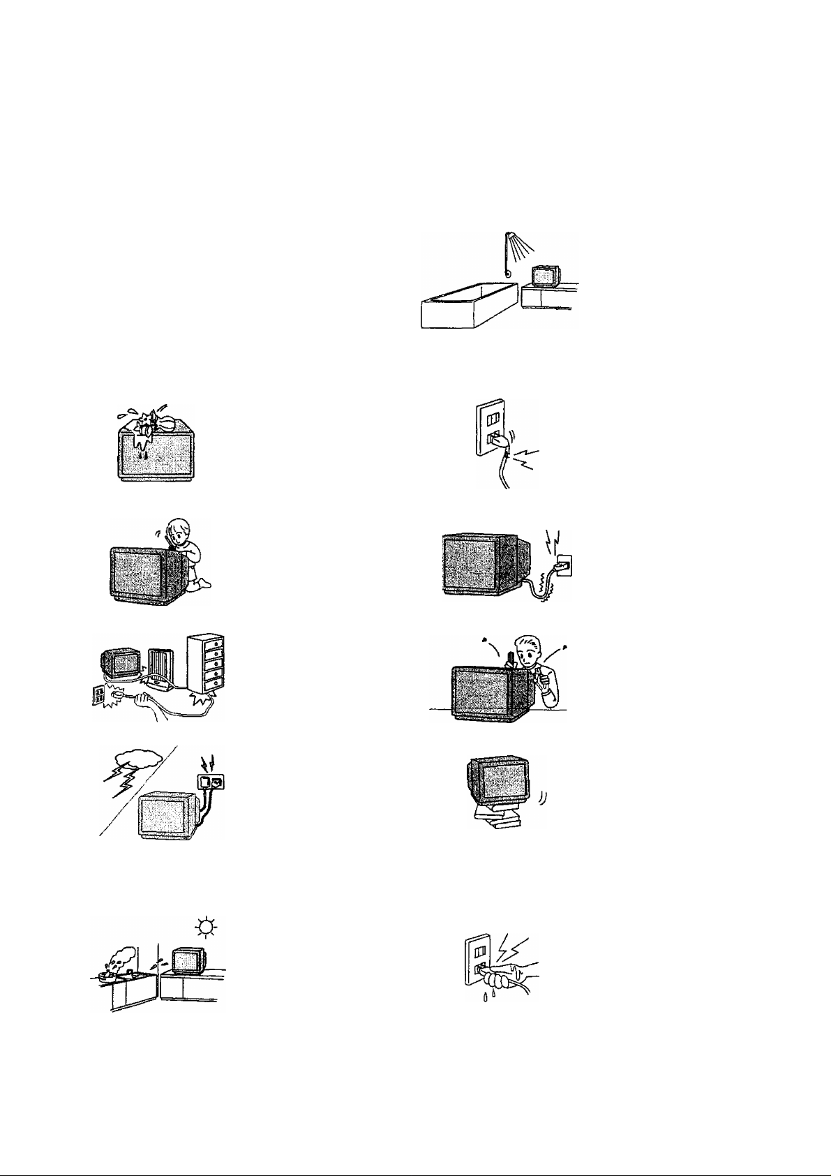
Warnings and Cautions
AWarninqs
Unplug the power cord in the
event of any malfunction
(screen goes blank, no sound,
odd sounds, smoke or unusual
si,
C«?5ì:PÌ>ÌE - 151
odors coming from the unit).
Unplug the power cord if
foreign matter or water falls
into the unit, or if the unit is
dropped or the cabinet is
damaged.
DO NOT use this unit near
water, (near a bath tub, etc.)
DO NOT place any of the
following on the unit:
Flower vases, flower pots,
cups, small metal objects, or
cosmetics containers,
chemicals or water.
DO NOT insert foreign objects
(metal or easily flammable
objects).
TAKE CARE NOT to damage
the power cord.
DO NOT touch the aerial cable
and this unit when there is
lightning.
DO NOT use if the power cord
or power plug is damaged, or
if the plug does not fit tightly
into the socket.
DO NOT use at a voltage other
than indicated
DO NOT remove the rear
cover as live parts and High
Voltage components are
accessible when the rear
cover is removed.
DO NOT place in an unstable
location
ACautions
DO NOT place in humid or
dusty location, or areas
exposed to smoke or steam.
DO NOT place in direct
sunlight and other sources
of direct heat.
DO NOT touch the power plug
if your hands are wet.
Warnings and Cautions
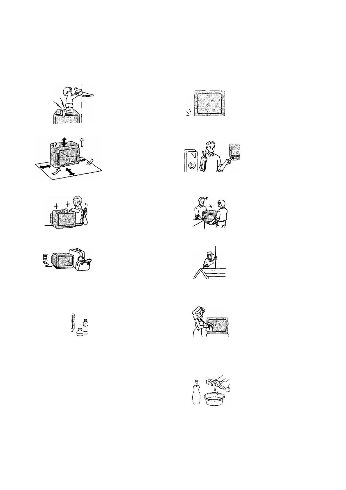
ACaution
DO NOT stand, or place heavy
objects on the unit.
Particular care should be taken
by tamilies with small children.
Adequate ventilation is
essential to prevent failure of
electrical components, we
recommend that a gap of at
least lOcm(^aii^) is left alt
around this unit even when it
is placed inside a cabinet or
between shelves.
Before cleaning, unplug the
power plug from the socket.
Unplug the power plug fmm the
socket if you are not going to
use the unit for an extended
period.
Place in a safe location.
Turn the power “Off" before
connecting other electrical
equipment.
DO NOT joint the unit.
Ask your sales outlet to install
the aerial.
Cleaning
“Í1
The unit contains many plastic
parts. For this reason DO NOT
use benzine, thinner or other
chemicals to clean the unit.
DO NOT bring into contact with
insecticide or other volatile
substances.
DO NOT allow the unit to come
into contact for extended
periods with rubber or vinyl
products.
Dust will accumulate on the
picture screen. Please wipe
with a soft cloth from time to
time, if you use a chemically
treated cloth, please be carefol
to follow the instructions that
come with the cloth.
Remove dirt and soiling by
wiping with a light cloth.
Even if the unit is heavily soiled,
do not apply cleaner directly to
the unit. Soak a cloth in a
solution of neutral cleanser
thinned with water. Then wring
out the cloth, wipe the unit
clean, and Hntsh by wiping with
a dry cloth.
Before Operating This Set
How to Use This Manual
1 .Check the Model Number of your TV set; the Mode! Number is shown on the rear cover name plate on the set.
Use the table on the opposite page to conflrm which features your particular Model is equipped with.This will help
you to known which sections of the manual apply to your set.
2.Check the Part Number on the rear of your Remote Control handpiece, and note the functions avallaWe, as shown
below.
TX-29P250X
TX-68P250Z
TX-80P250Z
TEXT Favourite
Page Selection—
TV/TEXT
Selection
Note:
• Mainly the remote control for TX-29P250X, TX-68P2502, TX-80P250Z is used as an example in the Operating
Instructions.
m TEXT Index
/Channel Search
TEXT hold
/Stilt
TC-29P250H
TC-34P250H
Picture AI
Picture DNR
Channel Search
Still
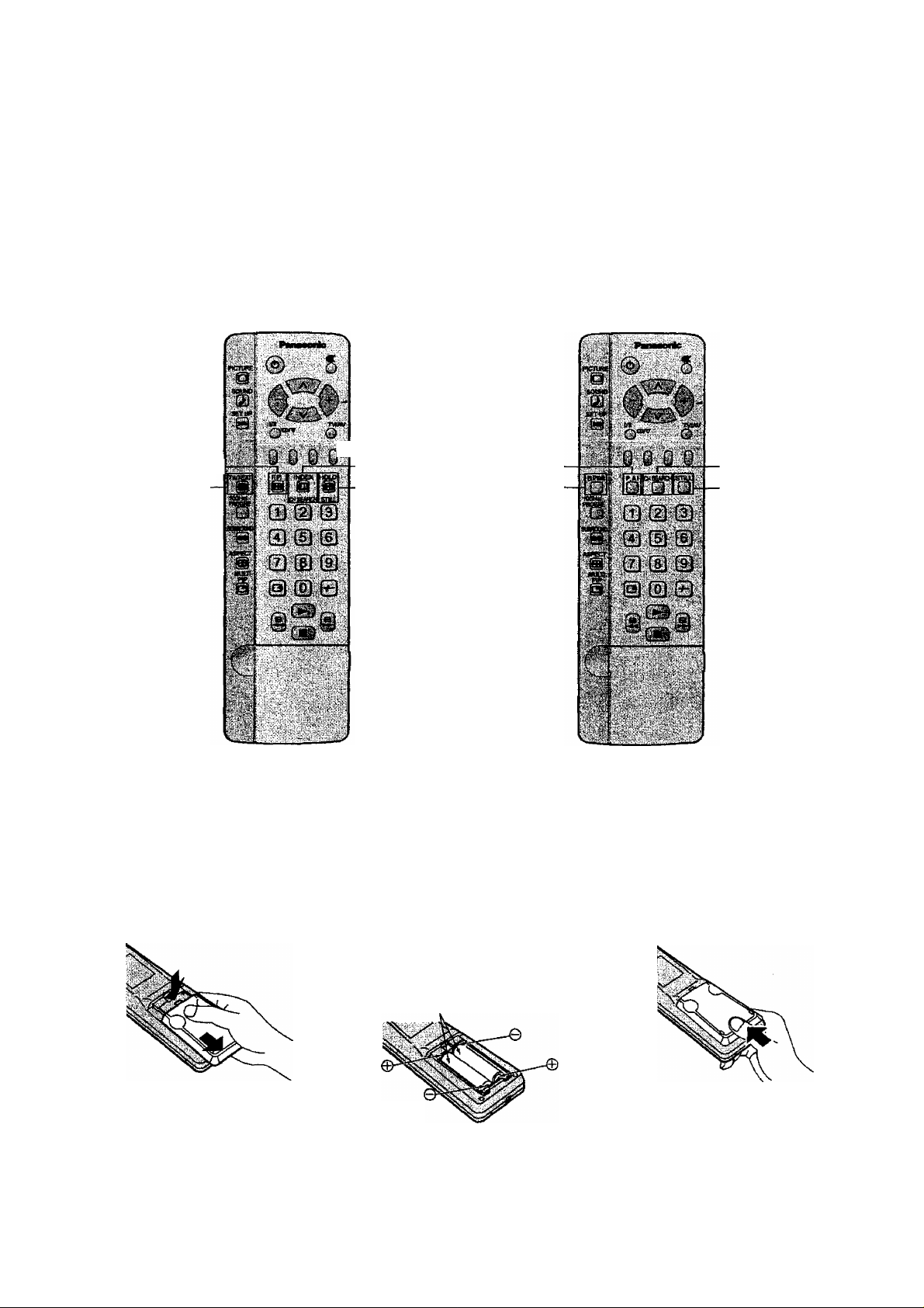
Battery Installation
1
Open the cover.
Apply slight downward pressure
white pulling towards the bottom.
Do not use rechargeable (Ni-Cd) batteries.
They are different in shape and performance and may fail to ensure correct operation.
Batteries; Use two '*R6 (AA}”size
batteries.
Insert the batteries ensuring correct polarity.
This is identifiable by the and symbols
on both the batteries and inside the battery
compartment.
Two ‘R6 (AA)' size
Replace the cover, and
slide in reverse until
the lock snaps.
Before Operating This Set
v:
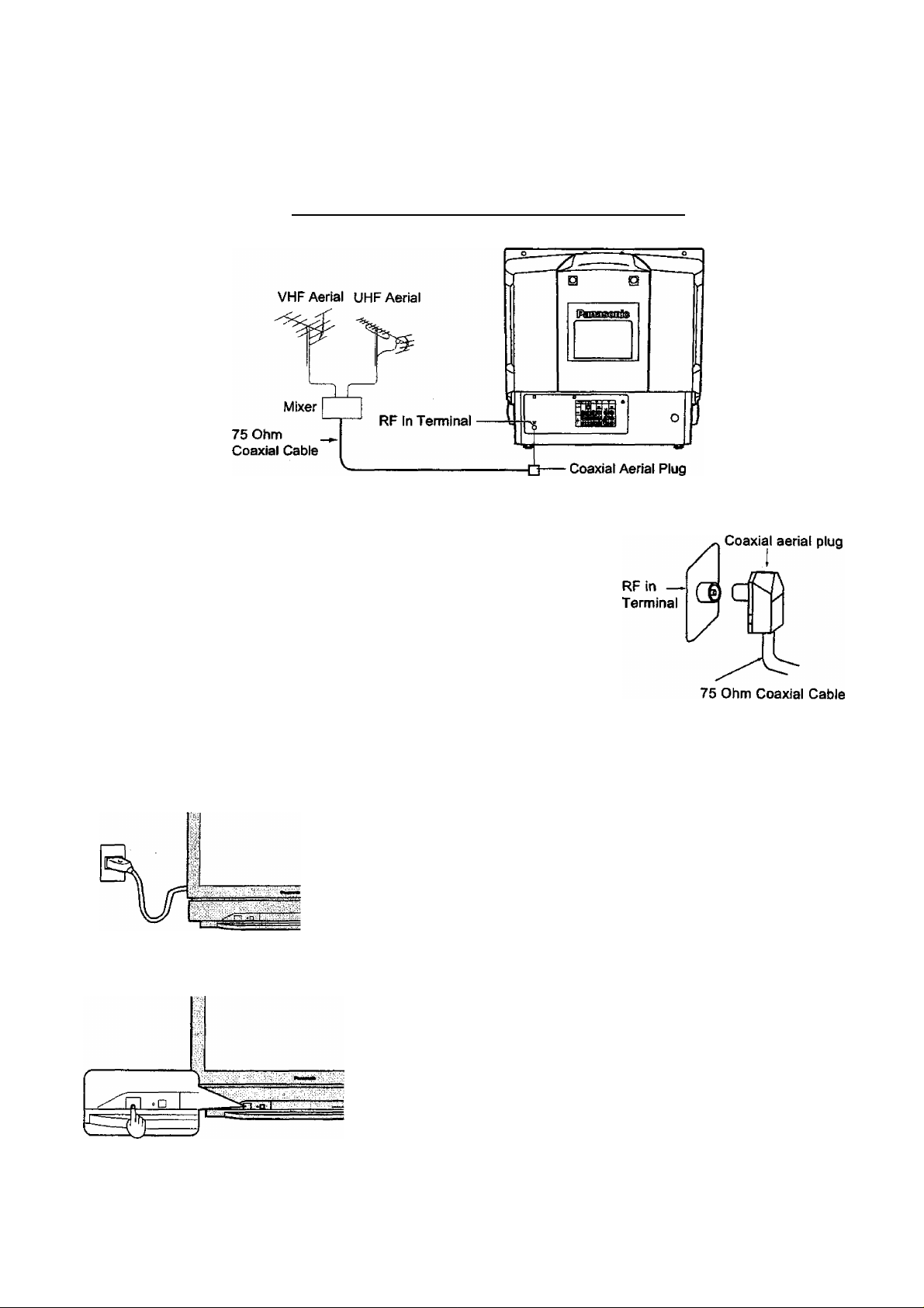
Connecting the Aerial cable to the RF In Terminal
To obtain optimum quality picture and sound, an Aerial, the correct cable (75
Ohm coaxial) and the correct terminating plug are required.
If a communal Aerial system is used, you may require the correct connection
cable and plug between the wall Aerial socket and your television receiver.
Your local Television Service Centre or Dealer may be able to assist you in
obtaining the correct Aerial system for your particular area and accessories
required.
Any matters regarding Aerial installation, upgrading of existing systems or
accessories required, and the costs incurred, are the responsibility of you, the
Customer.
Connecting the Plug to the Wall outlet
Note:
• Mains plug types vary between countries. The mains plug shown at left
may therefore not be the type fitted to your set.
How to turn the Power On
Press the Power switch on Television to turn the set on. (See page 14)
Location of Controls
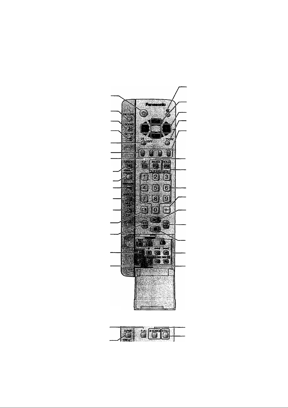
Remote Control
TX-29P250X, TX-68P250Z, TX-80P250Z
Power(Stand-by) (see page 14)
Picture Menu (see page 18)
Sound Menu (see page 20)
Sound Mute (see page 15)
Programme Number Up and Down
(see page 14)
Volume Up and Down (see page 15)
TV/AV Mode Selection (see page 15)
Set up Menu (see page 22)
Stereo/Bilingual Sound Selection
(see page 31)
TELE TEXT (see page 33)
TEXT Favourite Page Selection
(see page 34)
TV/TEXT Selection (see page 30)-
lOOHz/PRCXSRE (see page 19)-
Surround (see page 20) -
Aspect (see page 28) ■
PicUire in Picture Selection
(see page 29)
Recall (see page 15)
VCR/LD/DVD Rewind/Review
(see page 32)
Normalization Normalise
(see page 19)
Store (see page 15)
Coloured buttons used for
Aspect functions (see page 28)
Teletext functions (see page 33)
AV selection (see page 15)
TEXT Index (see page 34)
/Channel Search (see page 30)
-TEXT hold (see page 30)
/Still (see page 30)
Direct programme Number
Two Digit- programme Number
Selection (see page 14)
VCR/LD/DVD Play (see page 32)
VCR/LD/DVD Fast Forward/cue
(see page 32)
VCR/LD/DVD Stop (see page 32)
VCR/LD/DVD Control (see page 32)
Help (see page 17)
TX-29P250X, TX-68P250Z, TX-80P250Z
Picture Al (see page 19)
Picture DNR (see page 19)
8
Channel Search (see page 30)
Still (see page 30)
Location of Controls
Controls and Terminals on the TV
Item Function Refer to
No. Page No.
Main Headphones Jack 13
O
Sub Headphones Jack
o
AV3 Input Terminals
0
RGB Input Terminal
o
STR
0
Function
O
Volume Down (-)
0
Programme Number Down (v)
Volume Up (+) /
o
Programme Number Up (A)
/
13
10
12
15
15
14
14
Item
0
0
0
0
0
0
0
Function
TV/AV Selection
Aerial Terminal (RF In Terminal)
Monitor Output Terminals
AVI Input Terminals
AV2 Input Terminals
AV4 Input Terminals
DVD {Y. Pb. Pr ) Input
Refer to
Page
15
7
11
10
10
10
11
Connections
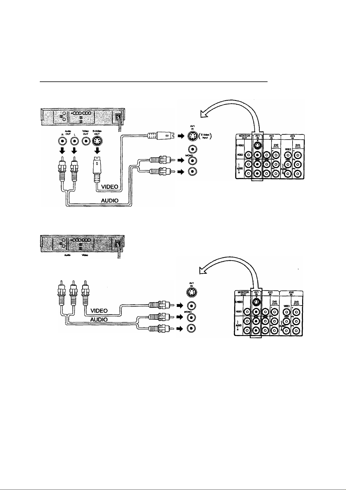
How to connect the “AV1, 2, 3 or 4” Input Terminals
Connect VCRs and other peripheral equipment
{Super-VHS VCR)
(VHS VCR)
OUT ^ OUT
© 0©
^
Notes:
• When an S-Video cable is connected to the S-Video terminal, the Video input will be automatically switched off for that
AV mode.
• When a Monaural VCR is used, connect the Monaural Audio cable to the Audio “L" (Left) terminal.
• Select the desired AV input position by pressing the TV/AV button. (Refer to page 15)
• Input 3 is located on the front of the unit.
• The AV2 and AV4 audio Input terminals serve as the audio input terminal for both the Video input and for the DVD input
AV2.
10
Connections
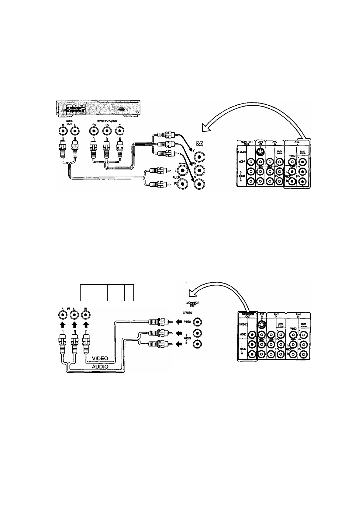
How to connect the DVD Input Terminals
DVD Player
Notes;
• The AV4 audio signal is common for both AV4 and DVD input signal terminals.
• The DVD signal input terminal takes priority over the AV4 video signal input terminal.
• Similar connection are available at the COMPONENT VIDEO input 2 terminal.
How to connect the AV Monitor Output Terminals to other equipment
The “Monitor Out” Terminals output the same signals as main picture on the TV screen and sound from the speaker at
that time, e.g.TV programmes or signals from AV1, AV2, AV3 or AV4 input.
Recording Equipment
(VHS VCR)
tD .
Notes:
• Never connect the same video recorder v/ith both the VIDEO IN and MONITOR OUT terminals on this TV set, as this
could cause incorrect operation.
• The monitor output emits the main picture normal video and audio signals.
• Teletext display on screen will not be output at the MONITOR OUT terminals.
• Even if the television is in picture-in-picture condition, MONITOR OUT terminals output the same signals as main
picture on the screen and sound from speakers. Sub picture including strobe, still, channel search, etc. will not be output
at the MONITOR OUT terminals.
• The RGB mode signal, and DVD signal (Y, Pb, Pr) are not output at the MONITOR out terminals.
■
11
Connections
How to connect the RGB Input Terminals
▼ L/MONO R
COMPUTER
8 Main QSub. 5-VIDEO VIDEQ AUpiO
Conversion adapter (if necessary)
PC cable
Notes:
• This unit can be connected to PCs with 640 X 480 (31.5 kHz / 60 Hz) or 640 X 400 (31.5 kHz / 70 Hz) pixel.
• In some cases other PCs may not work with this TV set.
■ There is no audio signal in RGB input.
• The sound of the RGB mode is combined with the Audio signal of AV3.
• Some PC models cannot be connected to the TV set.
• A commercially sold adapter is required to use the RGB cable (D-sub 15P) to connect a
PC-98 series computer (which has a D-sub 15P terminal) or a Macintosh computer to the TV set.
• There is no need to use an adapter for computers with DOSA/ compatible D-sub 15P terminal.
O O ©!-©-©-(?
D-SUB 15P
AV3
IN
RGB (31.SkHz)
Signal Names for D-sub 15P Connectcxr
®0(D(D0
Pin Layout for RGB Input
Terminal
Pin No.
©
12
Signal Name
R
G
B
GND(Ground)
GND(Ground)
Pin No. Signal Name
©
GND(Ground)
GND(Ground)
GND(Ground)
NC(not connected)
GND(Ground)
Pin No.
©
®
@
®
Signal Name
GND(Ground)
NC
HD/SYNC
VD
NC(not connected)
 Loading...