

Page 1
POWER
TV
DTV
TV/VIDEO
E
T
U
M
MENU
1 2 3
4 5 6
7 809
R-TUNE PROG
SWAP
REW
PAUSE
TV/VCR
TV/VCR
SAP
LIGHT
VCR DVD
DBS/CBL
RCVR
AUX
A -ANTENNA - B
S
T
L
C
E
E
E
P
P
S
A
R
E
C
A
L
L
CH
OK
VOLCHVOL
EXIT
SPLIT
PLAY
FF
REC
STOP
SPLIT CH
OPEN/CLOSE
DVD/VCR CH
TV
Operating Instructions
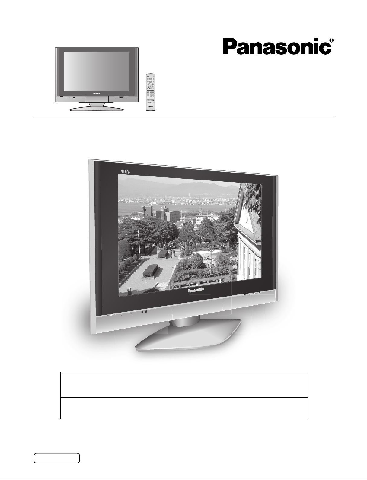
Wide LCD Television
Model No.
TC-32LX300
TV screen image is simulated.
For assistance, please call : 1-800-211-PANA (7262)
or send e-mail to : consumerproducts@panasonic.com
or visit us at www.panasonic.com (U.S.A.)
For assistance, please call : 787-750-4300
or visit us at www.panasonic.com (Puerto Rico)
Before connecting, operating or adjusting this product, please read these instructions completely.
Please keep this manual for future reference.
English
TQB2AA0527-1
Page 2
Important Safety Instructions
CAUTION
RISK OF ELECTRIC SHOCK
DO NOT OPEN
The lightning flash with arrow head
within a triangle is intended to tell
the user that parts inside the
product are a risk of electric shock
to persons.
The exclamation point within a
triangle is intended to tell the user
that important operating and
servicing instructions are in the
papers with the appliance.
■ Note to CATV System Installer: This reminder is provided to direct the CATV system installer’s attention to
Article 820-40 of the NEC that provides guidelines for proper grounding and, in particular, specifies that the cable
ground shall be connected to the grounding system of the building, as close to the point of cable entry as practical.
■ Important Safety Instructions for LCD TV
1) Read these instructions.
2) Keep these instructions.
3) Heed all warnings.
4) Follow all instructions.
5) Do not use this apparatus near water.
6) Clean only with dry cloth.
7) Do not block any ventilation openings. Install in accordance with the manufacturer’s instructions.
8) Do not install near any heat sources such as radiators, heat registers, stoves, or other apparatus (including amplifiers)
that produce heat.
9) Do not defeat the safety purpose of the polarized or grounding-type plug. A polarized plug has two blades with one
wider than the other. A grounding type plug has two blades and a third grounding prong. The wide blade or the third
prong are provided for your safety. If the provided plug does not fit into your outlet, consult an electrician for replacement
of the obsolete outlet.
10)Protect the power cord from being walked on or pinched particularly at plugs, convenience receptacles, and the
point where they exit from the apparatus.
11) Only use attachments / accessories specified by the manufacturer.
12) Use only with the cart, stand, tripod, bracket, or table specified by the manufacturer, or sold with the
apparatus. When a cart is used, use caution when moving the cart / apparatus combination to avoid injury
from tip-over.
13)Unplug this apparatus during lightning storms or when unused for long periods of time.
14)Refer all servicing to qualified service personnel. Servicing is required when the apparatus has been damaged in
any way, such as power-supply cord or plug is damaged, liquid has been spilled or objects have fallen into the
apparatus, the apparatus has been exposed to rain or moisture, does not operate normally, or has been dropped.
15)Operate only from the type of power source indicated on the marking label. If you are not sure of the type of power
supplied to your home, consult your television dealer or local power company.
16)Follow all warnings and instructions marked on the LCD TV.
17) Never push objects of any kind into this LCD TV through cabinet slots as they may touch dangerous voltage points
or short out parts that could result in a fire or electric shock. Never spill liquid of any kind on the LCD TV.
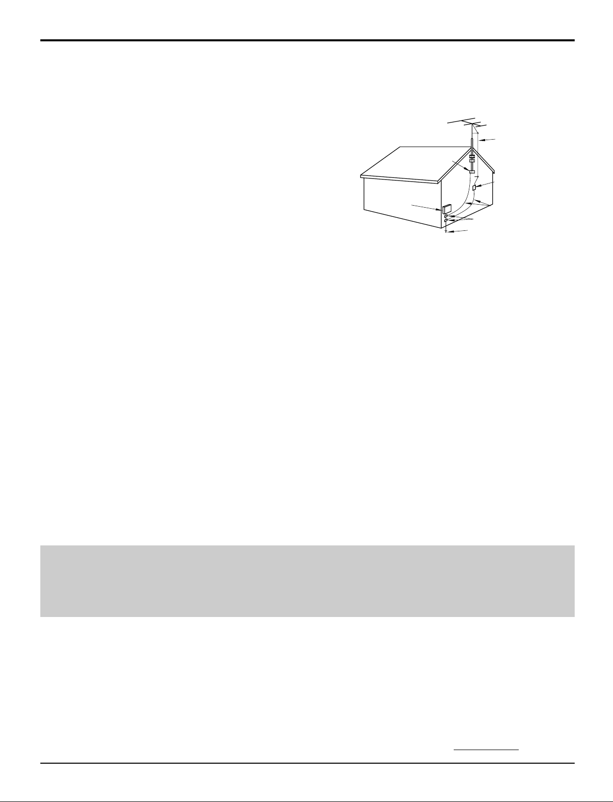
18)If an outside antenna is connected to the television equipment, be sure the antenna system is grounded so as to
provide some protection against voltage surges and built up static charges. In the U.S., Section 810-21 of the
National Electrical Code provides information with respect to proper grounding of the mast and supporting structure,
grounding of the lead-in wire to an antenna discharge unit, size of grounding conductors, location of antenna discharge
unit, connection to grounding electrodes, and requirements for the grounding electrode.
2
Page 3
Important Safety Instructions
19) An outside antenna system should not be located in the vicinity of
overhead power lines or other electric light or power circuits, or
where it can fall into such power lines or circuits. When installing
an outside antenna system extreme care should be taken to keep
from touching such power lines or circuits as contact with them
might be fatal.
20) Unplug this LCD TV from the wall outlet, and refer servicing to
qualified service personnel under the following conditions:
a. When the power cord or plug is damaged or frayed.
b. If liquid has been spilled into the LCD TV.
c. If the LCD TV has been exposed to rain or water.
d. If the LCD TV does not operate normally by following the
operating instructions.
Adjust only those controls that are covered by the operating
instructions as improper adjustment of other controls may result
in damage and will often require extensive work by a qualified
technician to restore the LCD TV to normal operation.
e. If the LCD TV has been dropped or the cabinet has been damaged.
f. When the LCD TV exhibits a distinct change in performance - this indicates a need for service.
21)When replacement parts are required, be sure the service technician uses replacement parts specified by the
manufacturer that have the same characteristics as the original part. Unauthorized substitutions may result in fire,
electric shock, or other hazards.
22)WARNING : TO REDUCE THE RISK OF FIRE OR ELECTRIC SHOCK, DO NOT EXPOSE THIS APPARATUS TO
RAIN OR MOISTURE.
DO NOT PLACE LIQUID CONTAINERS (FLOWER VASES, CUPS, COSMETICS, ETC.) ON THE
SET. (INCLUDING ON SHELVES ABOVE, ETC.)
23)CAUTION : TO PREVENT ELECTRIC SHOCK DO NOT USE THIS PLUG WITH A RECEPTACLE OR OTHER
OUTLET UNLESS THE BLADES CAN BE FULLY INSERTED TO PREVENT BLADE EXPOSURE.
24)CAUTION : USE WITH OTHER STAND MAY RESULT IN INSTABILITY CAUSING POSSIBLE INJURY.
25)CAUTION : DANGER OF EXPLOSION IF BATTERY IS INCORRECTLY REPLACED. REPLACE ONLY WITH THE
SAME OR EQUIVALENT TYPE.
Secure ventilation
•
Slots and openings in the cabinet and the back or bottom are provided for ventilation, and to ensure reliable operation
of the LCD TV and to protect it from overheating. These openings must not be blocked or covered. There should be at
least 10 cm of space from these openings. The openings should never be blocked by placing the LCD TV on a bed,
sofa, rug or other similar surface. This LCD TV should not be placed in a built-in installation such as a bookcase unless
proper ventilation is provided.
EXAMPLE OF ANTENNA
GROUNDING AS PER (NEC)
NATIONAL ELECTRICAL
CODE
GROUND
CLAMP
ELECTRIC
SERVICE
EQUIPMENT
ANTENNA
LEAD-IN WIRE
ANTENNA
DISCHARGE UNIT
(NEC SECTION 810-20)
GROUNDING CONDUCTORS
(NEC SECTION 810-21)
GROUND CLAMPS
POWER SERVICE GROUNDING
ELECTRODE SYSTEM
(NEC ART 250, PART H)
NOTES:•This equipment is designed to operate in North America and other countries where the broadcasting system
and AC house current is exactly the same as in North America.
The marking or retained image on the LCD panel resulting from fixed image use is not an operating defect
•
and as such is not covered by Warranty. This product is not designed to display fixed image patterns for
extended periods of time.
■
Important Information Regarding Use of Video Games, Computers, Captions or Other Fixed Image Displays.
The extended use of fixed image program material can cause a “shadow image” on the LCD panel.
This background image is viewable on normal programs in the form of a stationary fixed image. This type of LCD panel
deterioration can be limited by observing the following steps:
A. Reduce the brightness/contrast setting to a minimum viewing level.
B. Do not display the fixed image for extended periods of time.
C. Turn the power off when not in actual use.
■
This product utilizes tin-lead solder, and has a fluorescent lamp containing a small amount of mercury. Disposal of
these materials may be regulated in your community due to environmental considerations. For disposal or recycling
information please contact your local authorities, or the Electronics Industries Alliance:
www.eiae.org.
3
Page 4
Dear Panasonic Customer
Welcome to the Panasonic family of customers.
We hope that you will have many years of enjoyment with your new LCD TV.
To obtain maximum benefit from your TV, please read these instructions before making any adjustments,
and retain them for future reference.
Retain your purchase receipt, and record the model number and serial number of your set in the
space provided on the rear cover of these instructions.
For assistance, please call : 1-800-211-PANA (7262)
or send e-mail to : consumerproducts@panasonic.com
or visit us at www.panasonic.com (U.S.A.)
For assistance, please call : 787-750-4300
or visit us at www.panasonic.com (Puerto Rico)
Federal Communication Commission Information
This equipment has been tested and found to comply with the limits for a TV Broadcast Receiver, pursuant to Part 15 of the
FCC Rules. These limits are designed to provide reasonable protection against harmful interference in a residential
installation. This equipment generates, uses and can radiate radio frequency energy and, if not installed and used in
accordance with the instructions, may cause harmful interference to radio communications. However, there is no guarantee
that interference will not occur in a particular installation. If this equipment does cause or receive interference, which
can be determined by turning equipment off and on, the user is encouraged to try to correct the interference by one or more
of the following measures:
Reorient or relocate the TV antenna.
Increase the separation between TV and other equipment.
Connect TV into separate outlet from other equipment.
Consult the dealer or an experienced radio / TV technician for help.
FCC Caution: Pursuant to 47CFR, Part 15.21 of the FCC rules, any changes or modifications not expressly approved by
Matsushita Electric Corporation of America could result in harmful interference and would void the user’s authority to
operate this equipment.
Manufactured under license from Dolby Laboratories.
“Dolby” and the double-D symbol are trademarks of Dolby Laboratories.
HDMI, the HDMI logo and High-Definition Multimedia Interface are
trademarks or registered trademarks of HDMI Licensing LLC.
: SD Logo is a trademark.
CableCARDTM is a trademark of Cable Television Laboratories, Inc.
4
Page 5

Table of Contents
Important Safety Instructions ....................................... 2
Accessories .................................................................... 6
Remote control battery .................................................. 6
Installation ...................................................................... 7
Location of Controls ...................................................... 8
The Main Unit ................................................................ 8
The Remote Control ...................................................... 8
Connections ................................................................. 10
Antenna Connection ................................................... 10
Cable Box Connection ......................................... 10
Audio / Video Connections .......................................... 11
AUDIO OUT Connection ...................................... 11
VIDEO 1 / 2 INPUT Connection ........................... 12
COMPONENT VIDEO INPUT Connection .......... 12
HDMI Connection................................................. 13
CableCARD
Front Panel Connection .............................................. 14
Power ON / OFF ............................................................ 15
First Time Setup ........................................................... 15
Input Setup........................................................... 15
Auto Scan ............................................................ 16
Language ............................................................. 16
Watching TV programs ................................................ 17
VHF and UHF ............................................................. 17
Cable TV ..................................................................... 17
Menu Navigation .......................................................... 18
Picture ......................................................................... 20
Pic Mode .............................................................. 20
Back Light / Color / Tint / Brightness / Picture / Sharpness / Normal ..
Other Adjust ......................................................... 20
Audio ........................................................................... 22
Bass / Treble / Balance / Normal ......................... 22
Other Adjust ......................................................... 22
Channel ....................................................................... 24
Favorite ................................................................ 24
Captions ............................................................... 25
Timer ........................................................................... 27
Sleep .................................................................... 27
Timer .................................................................... 28
TM
Connection .......................................... 14
20
Clock Set.............................................................. 29
Day Set ................................................................ 29
Setup ........................................................................... 30
Program CH ......................................................... 30
Auto Scan ............................................................ 31
Manual Program .................................................. 31
Closed Caption .................................................... 33
Other Adjust ......................................................... 35
CableCARD
Lock ............................................................................ 36
Lock Set ............................................................... 36
Channel Lock ....................................................... 37
Block Program ..................................................... 37
How Long? ........................................................... 39
Password ............................................................. 39
Card operations............................................................ 40
Inserting and removing a card ............................. 40
Compatible card type and card size..................... 40
Folders and Files ................................................. 41
SD Menu ..................................................................... 42
SD Record ........................................................... 42
Movie Menu ......................................................... 43
Picture Menu ........................................................ 44
Record Setting ..................................................... 45
Format.................................................................. 46
Memory Left ......................................................... 46
SPLIT Operation ........................................................... 48
To swap the pictures ............................................ 48
To select the input mode of SPLIT frame ............. 48
Aspect Controls ........................................................... 49
Operating peripheral equipment using the remote control ...
Programming the remote control code ........................ 50
To find a code not listed in the index.................... 50
Infrared Code Index .................................................... 51
Mode Operational Key Chart ...................................... 54
Troubleshooting ........................................................... 56
Specifications ............................................................... 57
Maintenance ................................................................. 57
Limited Warranty .......................................................... 58
Customer Services Directory ...................................... 60
TM
...................................................... 35
50
5
Page 6
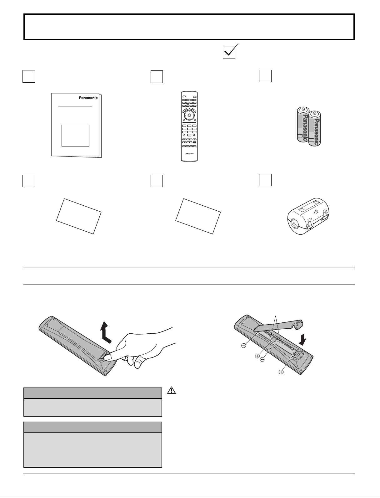
Accessories
Check that you have the accessories and items shown
Operating
Instruction book
Remote control
EUR7627Z30
POWER
SAP
LIGHT
TV
VCR DVD
DBS/CBL
RCVR
AUX
DTV
A -ANTENNA - B
TV/VIDEO
S
T
L
C
E
E
E
P
P
S
A
R
E
E
C
T
A
U
L
L
M
CH
OK
VOLCHVOL
MENU
EXIT
1 2 3
4 5 6
7 809
PROG
R-TUNE
SPLIT
SWAP
PLAY
REW
FF
PAUSE REC
STOP
SPLIT CH
OPEN/CLOSE
DVD/VCR CH
TV/VCR
TV
Customer card Customer care plan card
Batteries for the remote
control
(AA Battery × 2)
Ferrite core
(for HDMI cable) ( × 1)
Remote control battery
1. Open the cover.
Helpful Hints:
For frequent remote control users, replace old
batteries with alkaline batteries for longer life.
Helpful Hints:
Whenever you remove the batteries, you may
need to reset the remote control infrared
codes. We recommend that you record the code
on page 50, prior to setting up the remote control.
2. Install the batteries and replace the cover.
Note the correct polarity (+ and -).
Two AA size
Precaution on battery use
Incorrect installation can cause battery leakage and corrosion that
will damage the remote control transmitter.
Observe the following precautions:
1. Batteries should always be replaced as a pair. Always use new
batteries when replacing the old set.
2. Do not combine a used battery with a new one.
3. Do not mix battery types (example: “Zinc Carbon” with “Alkaline”).
4. Do not attempt to charge, short-circuit, disassemble, heat or burn
used batteries.
5. Battery replacement is necessary when remote control acts
sporadically or stops operating the TV set.
6
Page 7
Installation
Receiver Location
Locate for comfortable viewing. Avoid placing where sunlight or other bright light (including reflections) will fall on the
screen.
Use of some types of fluorescent lighting can reduce remote control transmitter range.
Adequate ventilation is essential to prevent internal component failure. Keep away from areas of excessive heat or moisture.
Optional External Equipment
The Video / Audio connection between components can be made with shielded video and audio cables. For best
performance, antenna cables should utilize 75 Ω coaxial shielded wire. Cables are available from your dealer or electronic
supply store.
Before you purchase any cables, be sure you know what type of output and input connectors your various components
require. Also determine the length of cable you’ll need.
For Optimum Quality Picture
When the LCD is exposed to light from outdoors or lighting fixtures, high-contrast pictures may not be displayed clearly. Turn
off florescent lamps near the LCD and place in a location not exposed to outdoor light.
How to Hang the LCD TV on the Wall
Wall-mounting this LCD TV should be done with the following optional accessory only. Wall-mounting with any other type
of bracket may cause instability which could result in the possibility of damage or injury.
Wall-hanging bracket................................................ TY-WK32LX20W
•
Please consult a qualified technician to perform proper installation.
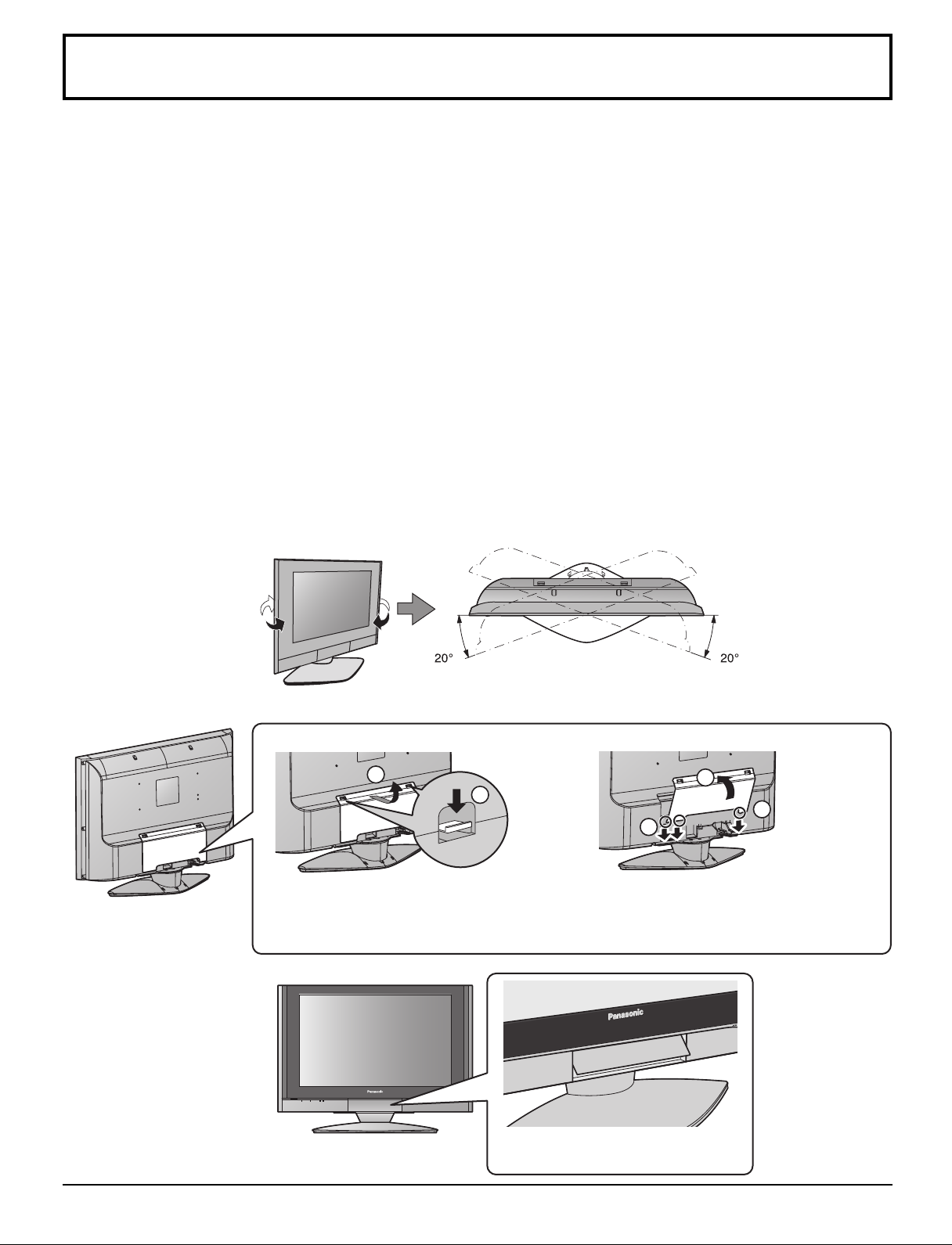
How to Use the LCD Stand
Adjust the stand to the desired angle. The stand angle can be adjusted between 20 ° left and 20 ° right.
Cable cover Removal and Reinstallation
Removal
1. Push down hooks and pull the cover
slightly towards you to disengage the
claws (at 3 points).
2. Slowly pull out in the downward direction.
Opening Front Control Door
Reinstallation
2
1
1
1. Insert the claws (at 3 points) at the
bottom.
2. Push the cover until hooks click into
place.
PULL
Raise the lower part of the door
labeled “PULL”.
2
1
7
Page 8
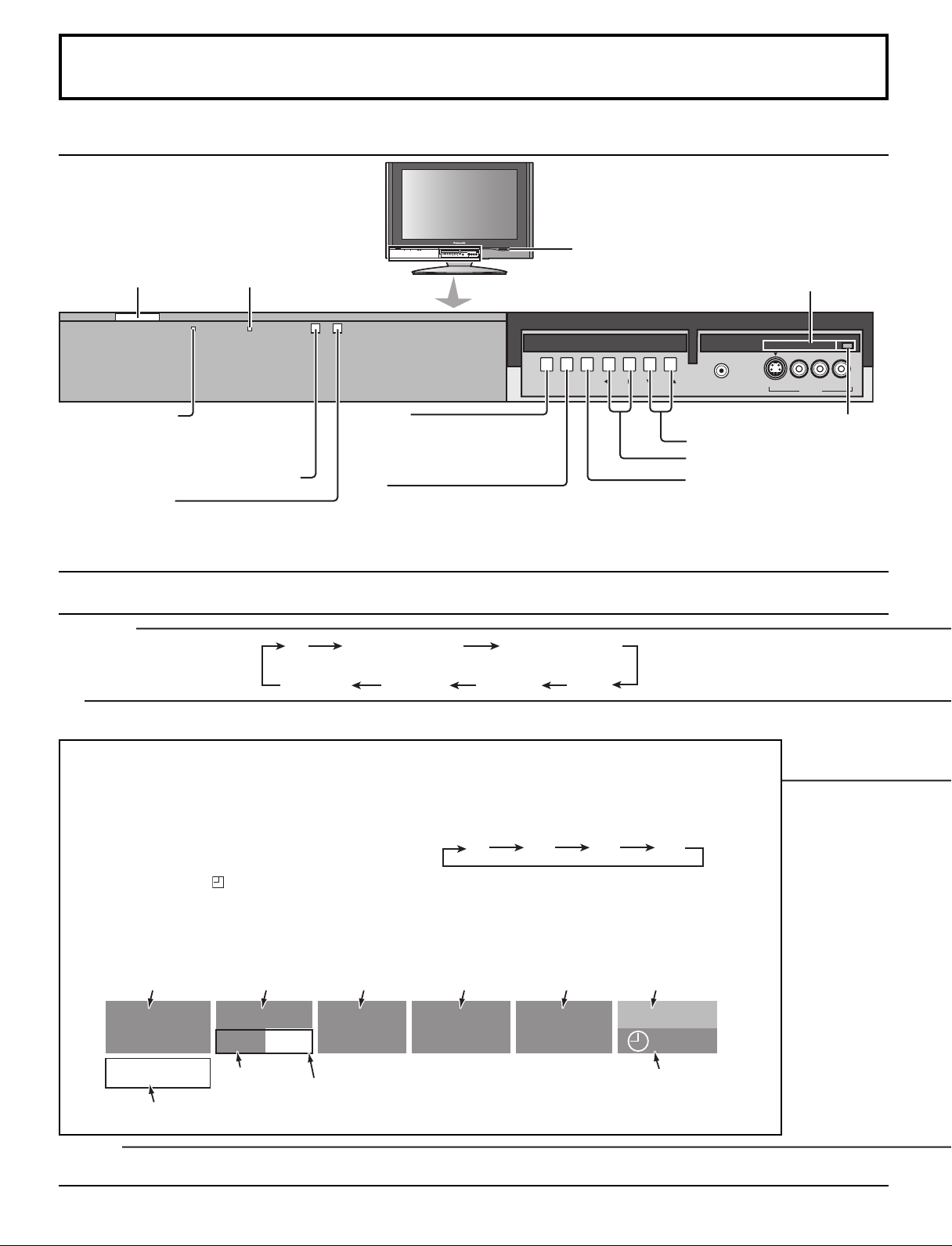
Location of Controls
30 60 90
0
The Main Unit
POWER button
SLEEP indicator
PC CARD
EJECT
TV/VIDEOOKMENU VOLUME CHANNEL
L
-
AUDIO-R
S VIDEOHPJ VIDEO
INPUT 3
SD CARD slot
PC CARD slot
Power indicator
Power on : Red
Power off : No Light
Remote control sensor
C.A.T.S. sensor
TV/VIDEOOKMENU VOLUME CHANNEL
MENU
Display Main Menu or return
one step backward in menus
(see page 18).
OK
Choose menu and submenu entry.
PC CARD
S VIDEOHPJ VIDEO
PC CARD EJECT button
Channel selectors
Volume adjusters
TV/VIDEO
Change the input mode.
INPUT 3
-
L
EJECT
AUDIO-R
LCD C.A.T.S. (Contrast Automatic Tracking System) automatically senses the ambient light conditions and adjusts the
brightness and gradation accordingly, to optimize contrast.
C.A.T.S. is in effect when Pic Mode is set to Auto (see page 20).
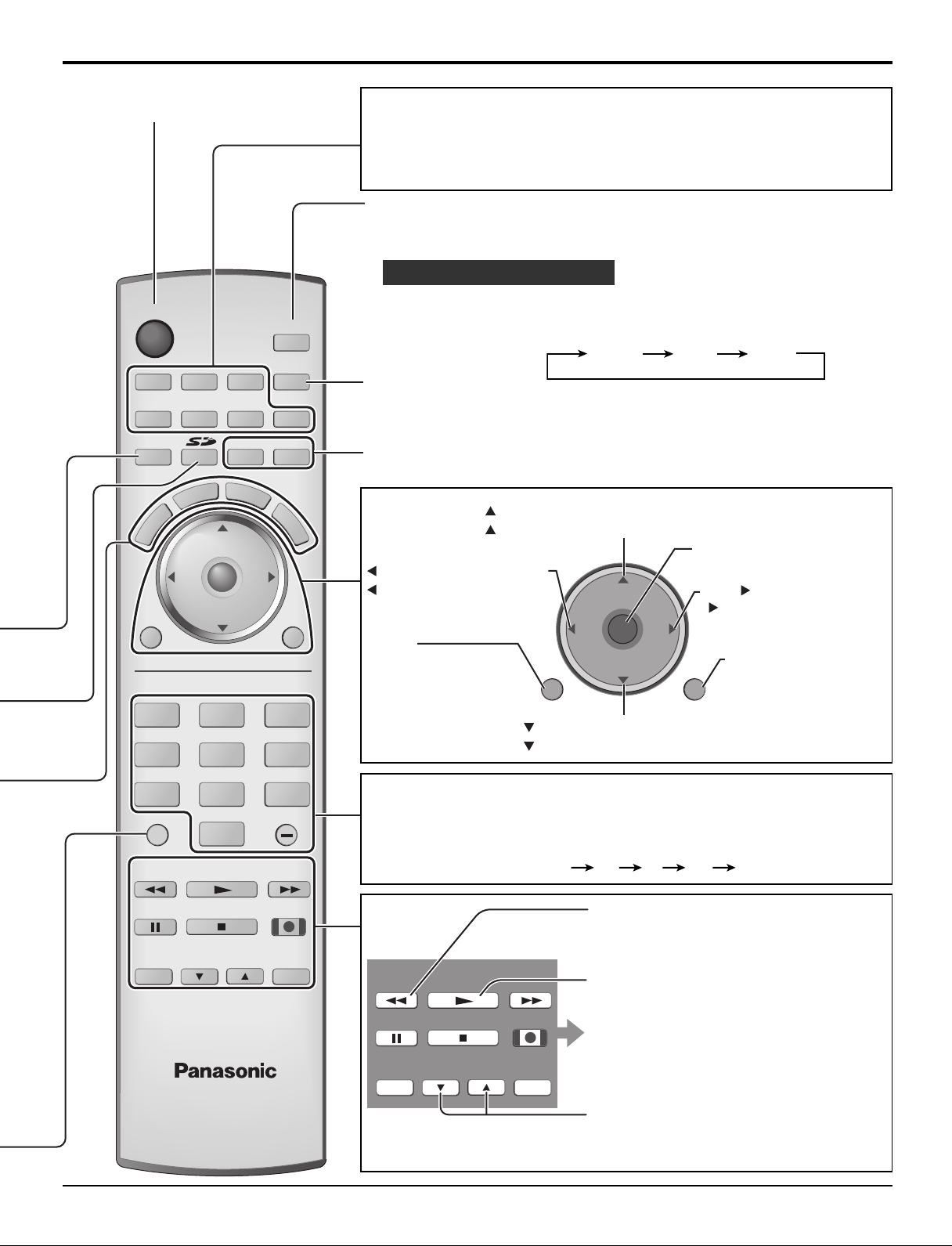
The Remote Control
TV/VIDEO
Change the input mode.
TV
COMPONENT 1
SD
Access Card operations (see page 42).
MUTE
Mute the sound. Press again to cancel the mute.
ASPECT
Change the picture aspect (see page 49).
SLEEP (TV mode)
Set the sleep time to put the TV into standby mode.
• When 3 minutes left, “
3 ” will flash. (“2” for 2 minutes and “1” for 1 minute).
• The SLEEP timer is cancelled when the power is turned off.
RECALL
Display or remove the channel banner.
Antenna designation,
Channel and program #
and Station identifier
Rating
Program
Aspect
Picture mode
setting
COMPONENT 2
VIDEO 1VIDEO 3 VIDEO 2
SPLIT CH
number or
Input information Clock
HDMI
A: 15-1
KPBS - HD
Add FAV
Press OK button to add or delete the channel
in the Favorite channel list (see page 24).
TV-G 1080i
SAP
CC
Closed Caption
SAP indication
R-TUNE
Switch to previously viewed channel and input modes.
8
VIVID HDMI
12:30 pm
30
Time remaining
in Sleep Timer
Page 9
TV
POWER
MENU
R-TUNE
FF
SPLIT
PLAY
PROG
EXIT
VCR DVD
DTV
RCVR
DBS/CBL
LIGHT
TV/VIDEO
A -ANTENNA - B
SAP
1 2 3
4 5 6
7 8
0
9
AUX
A
S
P
E
C
T
M
U
T
E
R
E
C
A
L
L
S
L
E
E
P
STOP
TV
PAUSE
OPEN/CLOSE
SPLIT CH
DVD/VCR CH
TV/VCR
REC
CH
VOL
CH
VOL
OK
SWAP
REW
Location of Controls
CH
VOL
CH
VOL
OK
MENU EXIT
Stereo SAP Mono
POWER
Turn the TV ON or OFF.
Mode Selection buttons (see page 50)
TV: TV
VCR: VCR
DVD: DVD
DTV: Digital TV
RCVR:Receiver/Amplifier
DBS: Digital Broadcasting Satellite
CBL: Cable TV
AUX: Aux
SAP
• Digital channel
Select the audio track (if available).
Audio Track 1 of 1 (English)
• Analog channel
Cycle through different audio modes.
ex. If receiving Stereo, SAP and Mono or receiving Stereo
and Mono only:
LIGHT
Light the remote control buttons. The selected mode button blinks when lit.
A -ANTENNA - B
Switch to (A or B) RF antenna input.
CH: Change to the next channel up.
: Move cursor upward during menu mode.
Choose menu and
VOL : Reduces volume.
: Move cursor to the left
during menu mode.
submenu entry.
VOL : Increase volume.
: Move cursor to the right
during menu mode.
MENU
Display Main Menu
or return one step
EXIT
Exit menus.
backward in menus
(see page 18).
CH: Change to the next channel down.
: Move cursor downward during menu mode.
Direct program number selection buttons
PROG -: When tuning a digital channel, press the button to enter the minor
number in a compound channel number.
• To enter the channel number
ex. CH 15-1: [1] [5] [-] [1] [OK]
SWAP
Swap pictures in SPLIT operations
(see page 48).
SWAP
REW
SPLIT
PLAY
FF
SPLIT
Split Screen (see page 48).
PAUSE
TV/VCR
STOP
SPLIT CH
DVD/VCR CH
REC
OPEN/CLOSE
Operation of other Device
(see pages 54, 55)
SPLIT CH
Select the channel during SPLIT
operations (see page 48).
9
Page 10
BA
Cable In
ANT
Connections
BA
Cable In
ANT
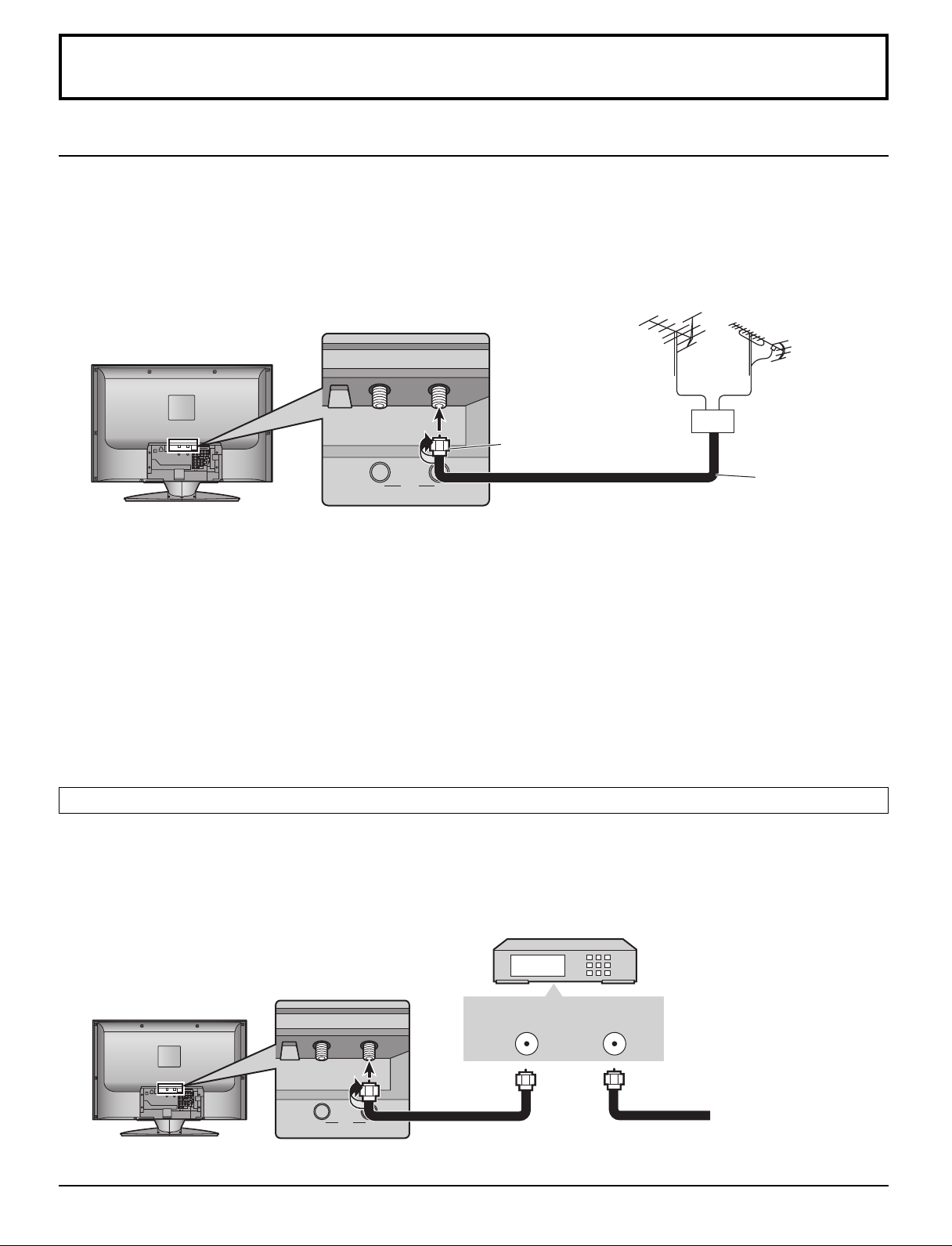
Antenna Connection
• For proper reception of VHF/UHF channels, an external antenna is required. For best reception, an outdoor antenna is
recommended.
•To view over-the-air TV programs only, connect the home antenna to ANTENNA (A).
To view over-the-air TV programs and cable TV programs, connect the cable TV’s cable to ANTENNA (A), and the
terrestrial antenna cable to ANTENNA (B).
• Select the antenna mode in Input Setup (see page 15).
VHF antenna
F-Type Antenna
Adapter (supplied)
UHF antenna
Mixer
75 Ω coaxial cable
Notes:
• Certain cable systems offset some channels to reduce interference or have premium (scrambled) channels. A cable
converter box is required for proper reception. Check with your local cable company for its compatibility requirements.
•To obtain optimum picture and sound, an antenna, the correct cable (75 Ω coaxial) and the correct terminating connector
are required.
• If a communal antenna system is used, you may need the correct connection cable and plug between the wall antenna
socket and your television receiver.
•Your local television service center or dealer may be able to assist you in obtaining the correct antenna system for your
particular area and the accessories required.
• Any matters regarding antenna installation, upgrading of existing systems or accessories required, and the costs incurred,
are your responsibility.
Cable Box Connection
• To view cable TV programs only, connect the cable TV’s cable to ANTENNA (A). When you enjoy both the terrestrial TV
programs and the cable TV programs, connect the cable TV’s cable to ANTENNA (A), and the terrestrial antenna
cable to ANTENNA (B).
• Select the antenna mode in Input Setup (see page 15).
CABLE BOX
10
ANT OUT ANT IN
Incoming 75 Ω Cable
from Cable Company
Page 11
Audio / Video Connections
RL
AUDIO
AUDIO OUT
DIGITAL AUDIO OUT
AUDIO IN
L
R
OPTICAL IN
VIDEO
P
R
RL
1
2
1
2
P
B
Y
AUDIO
COMPONENT
VIDEO
VIDEO S-VIDEO
INPUT
AUDIO OUT
INPUT
HDMI
AUDIO IN
DIGITAL AUDIO
OUT
Connections
COMPONENT
VIDEO
INPUT
VIDEO
P
P
R
B
Y
1
2
DIGITAL
AUDIO OUT
AV IN
RL
AUDIO
AUDIO OUT
VIDEO S-VIDEO
HDMI
AUDIO IN
INPUT
1
2
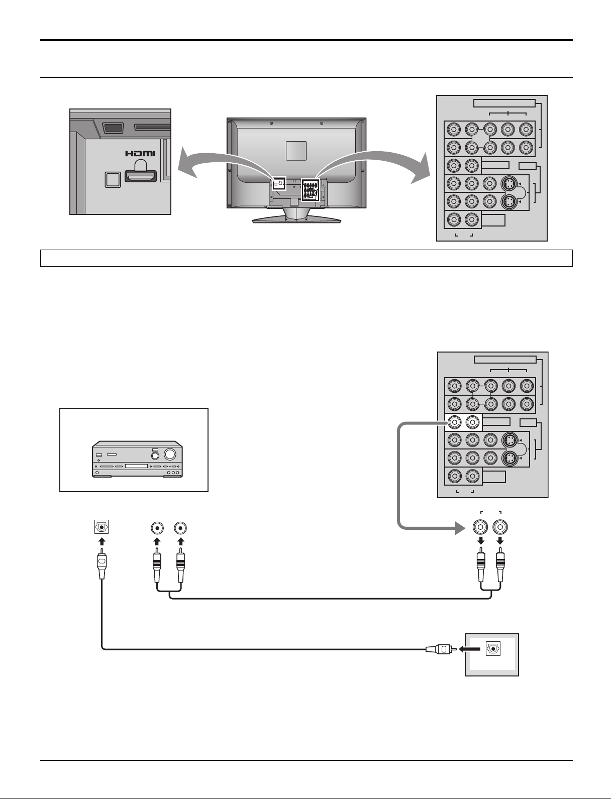
AUDIO OUT Connection
For a full Home Theater sound experience, an external Dolby Digital∗ decoder and a multichannel amplifier must be
connected to the DIGITAL AUDIO OUT terminal on the TV.
∗Dolby Digital 5.1 channel surround sound delivers digital-quality sound. Dolby Digital provides five discrete full-bandwidth
channels for front left, front right, center, surround left and surround right, plus a LFE (Low Frequency Effect) subwoofer
channel.
Example of output audio connection
Amplifier
Audio cable
Optical digital audio cable
or
Notes:
• External speakers cannot be connected directly to AUDIO OUT terminals.
• When ATSC channel is selected, the output from the DIGITAL AUDIO OUT jack will be Dolby Digital. When NTSC
channel is selected, the output will be PCM.
11
Page 12
Connections
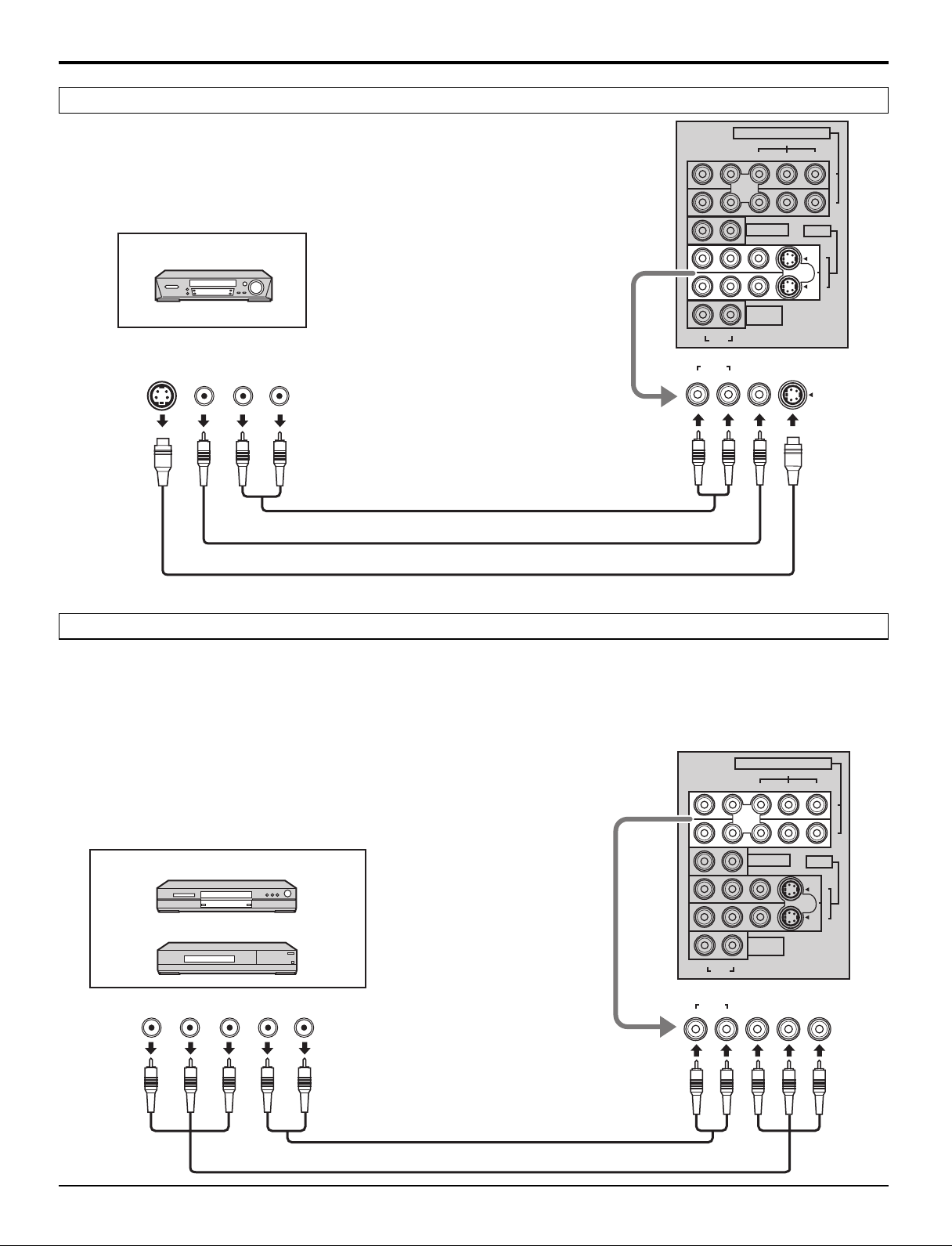
VIDEO 1 / 2 INPUT Connection
COMPONENT
P
R
VIDEO
VIDEO
P
INPUT
B Y
1
Example of input signal source
VCR
S-VIDEO
OUT
VIDEO
OUT
R
AUDIO
OUT
L
Note:
Connect the S-VIDEO or VIDEO terminal.
COMPONENT VIDEO INPUT Connection
Audio cable
Video cable
S-Video cable
RL
AUDIO
INPUT 1 / 2
AUDIO
RL
AUDIO OUT
VIDEO S-VIDEO
HDMI
AUDIO IN
S-VIDEOVIDEO
2
INPUT
1
2
This TV is capable of displaying 1080i and 480p DTV signals when connected to a DTV Tuner Set-Top Box (STB). This
TV also utilizes a progressive scan doubler, which de-interlaces the NTSC signal and progressively scans the image.
This allows you to sit close to the TV and not see the thin black horizontal lines (venetian blind effect) associated with
interlaced TV pictures.
•To view DTV programs, connect the STB to the component video input terminals (Y, PB, PR) of the TV. Component video
inputs provide luminance and separate color signals.
• Set the output of the STB to either 1080i or 480p.
•A DTV signal must be available in your area.
• Use a Panasonic DTV-STB (Digital TV-Set-Top Box) or DVD Player.
Example of input signal source
DVD player
Digital TV-Set-Top Box (DTV-STB)
COMPONENT VIDEO OUT
P
B
P
R
AUDIO OUT
Y
L
R
COMPONENT VIDEO INPUT 1 / 2
COMPONENT
RL
AUDIO
AUDIO
RL
VIDEO
VIDEO
P
P
R
B
AUDIO OUT
VIDEO S-VIDEO
HDMI
AUDIO IN
PBY
P
R
INPUT
Y
1
2
INPUT
1
2
12
Audio cable
Component Video cable
Page 13
AV I N
RL
AUDIO
HDMI AUDIO IN
HDMI IN
HDMI OUT
L
R
VIDEO
P
R
RL
1
2
1
2
P
B
Y
AUDIO
COMPONENT
VIDEO
VIDEO S-VIDEO
INPUT
AUDIO OUT
INPUT
HDMI
AUDIO IN
AUDIO
OUT
1
2
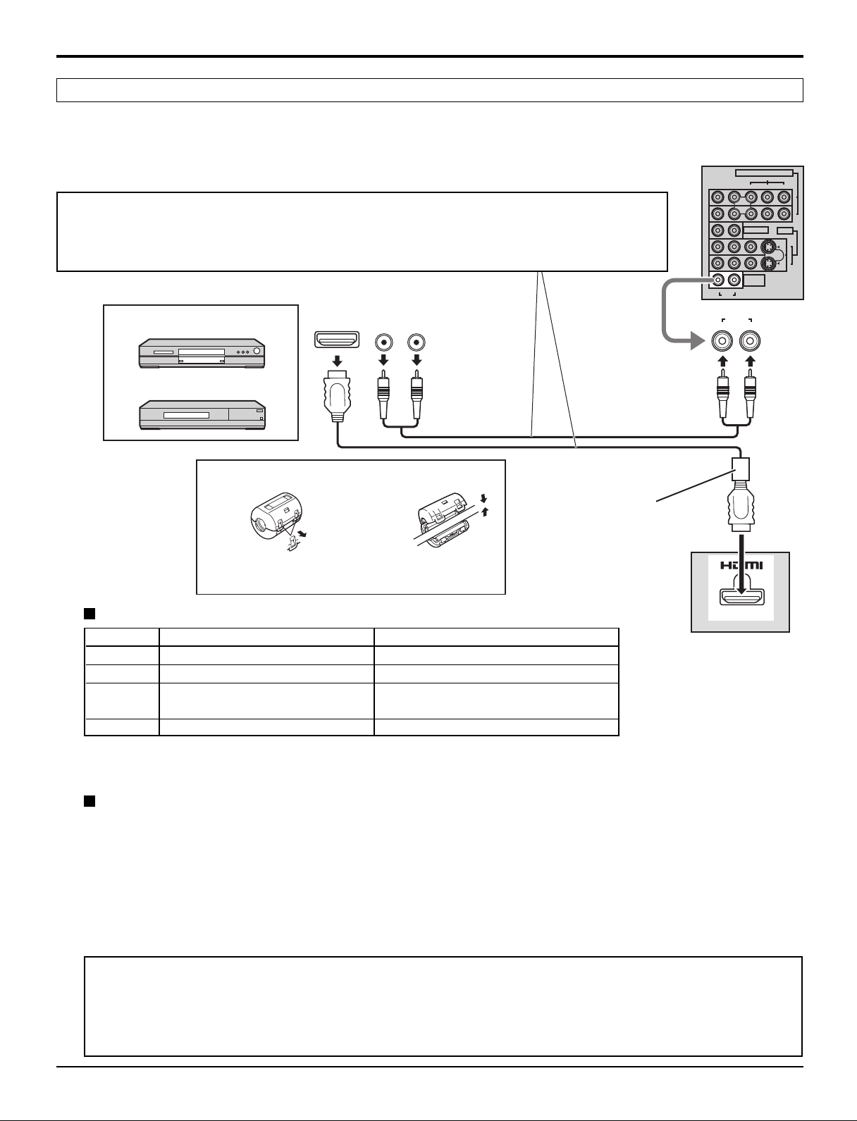
HDMI Connection
1
∗
HDMI
uncompressed standard. The HDMI terminal supports both video and audio information.
An EIA/CEA-861/861B
connected to the HDMI input terminal.
(High Definition Multi media Interface) is the first all-digital consumer electronics A/V interface that supports
2
∗
-compliant device, such as a Set-Top Box or DVD player with HDMI or DVI output terminal can be
3
• If the external device has DVI output only, use a DVI to HDMI adapter cable
∗
to connect to the
HDMI terminal.
• Connect the audio cables to the AUDIO IN terminals when using a DVI to HDMI adapter cable.
• Select the audio setting in HDMI In (see page 23).
Example of HDMI input signal source
DVD player
Set-Top Box
Audio cable
Connections
Attaching the ferrite core
HDMI cable
Ferrite core (supplied)
Attach just beside the connector.
Pull back the tabs (in two
places) to open.
Put the cable
and close.
Compatible VIDEO Signal
× ×
×
× ×
×
× ×
720p
× ×
×
× ×
1,080i
480p
480p
× ×
×
× ×
480i
× ×
V)
Vertical scanning frequency (Hz)
59.94/60
59.94/60
59.94/60
59.94/60
59.94/60
No. of dots (H
720p
1080i
480p
480i
1,280
1,920
720
640
720
×
× ×
×
× ×
× ×
× ×
Notes:
• This input terminal is not intended for use with computers.
• 720p/1080i signals will be re-formatted to view on your LCD display.
Compatible sampling freguency of AUDIO signal through HDMI (L.PCM) : 48 kHz / 44.1 kHz / 32 kHz
Notes:
• This HDMI connector is Type A.
• If you connect equipment without a digital output terminal, connect to the COMPONENT VIDEO, S-VIDEO or
VIDEO input terminal on the TV so you can receive an analog signal.
• The HDMI IN terminal can only be used with 720p, 1080i, 480i or 480p picture signals. Set the Digital Set -Top Box
DIGITAL OUT terminal Output setting to 720p, 1080i, 480i or 480p. For detailed information, refer to the Digital Set
-Top Box instruction manual. If you cannot display the picture because your Digital Set -Top Box does not have a
DIGITAL OUT terminal Output setting, use the component Video Input (or the S-Video Input or Video Input). In this
case the picture will be displayed as an analog signal.
1. HDMI, the HDMI logo and High-Definition Multimedia Interface are trademarks or registered trademarks of
∗
HDMI Licensing LLC.
2. EIA/CEA-861/861B profiles compliance covers profiles for transmission of uncompressed digital video
∗
including high bandwidth digital content protection.
3. HDMI-DVI conversion cable (TY-SCHO3DH): available on Panasonic website (www.panasonic.com). Consult
∗
your consumer electronics dealer for availability.
13
Page 14
Connections
BA
Cable In
ANT
CableCARDTM Connection
CableCARD
TM
allows you to tune digital and high definition cable channels through the cable antenna. Consult your cable
company on the availability of CableCARDTM.
Procedure
1. Connect the cable antenna to ANTENNA (A).
2. Turn the TV on (see page 15).
3. Set the input mode to TV (see page 8).
4. Insert the CableCARD
TM
(with upper side facing out) into CableCARDTM slot on the back of the TV.
Follow the messages displayed on the screen.
INSERT THIS END
POD MODULE
Upper side of the card
Notes:
• If you experience keyboard or remote control function hang-up when using CableCARDTM, unplug the TV and plug it back
in and try the controls again. If this condition still exists, please call Panasonic Customer Call Center for further instructions.
• Do not insert a PC card into CableCARDTM slot.
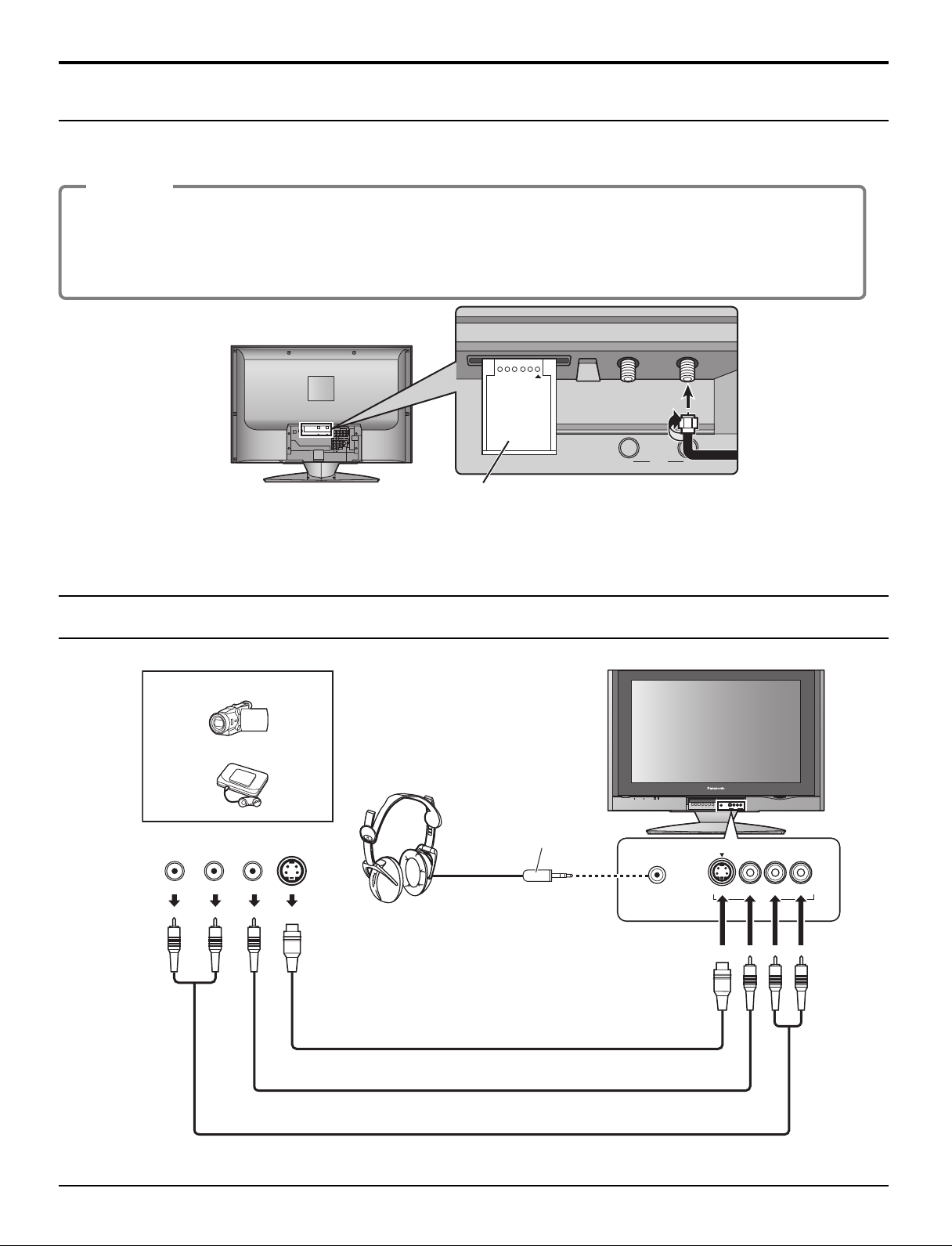
Front Panel Connection
Example of input signal source
CAMCORDER
VIDEO GAME CONSOLE
L
AUDIO
OUT
R
VIDEO
OUT
S-VIDEO
OUT
S-Video cable
Headphones /
Earphones
(not supplied)
M3 plug
PC CARD
TV/VIDEOOKMENU VOLUME CHANNEL
S VIDEOHPJ VIDEO
ELECT
L
-
AUDIO-R
S VIDEOHPJ VIDEO
INPUT 3
-
AUDIO-R
L
INPUT 3
Video cable
Audio cable
Note:
Connect the S-VIDEO or VIDEO terminal.
14
Page 15
TV VCR DVD
RCVR
LIGHT
SAP
AUX
POWER
DTV
DBS/CBL
TV
POWER
VCR DVD
RCVR
LIGHT
TV/VIDEO
A -ANTENNA - B
SAP
1 2 3
AUX
A
S
P
E
C
T
M
U
T
E
R
E
C
A
L
L
CH
VOL
CH
VOL
OK
MENU EXIT
DTV
DBS/CBL
S
L
E
E
P
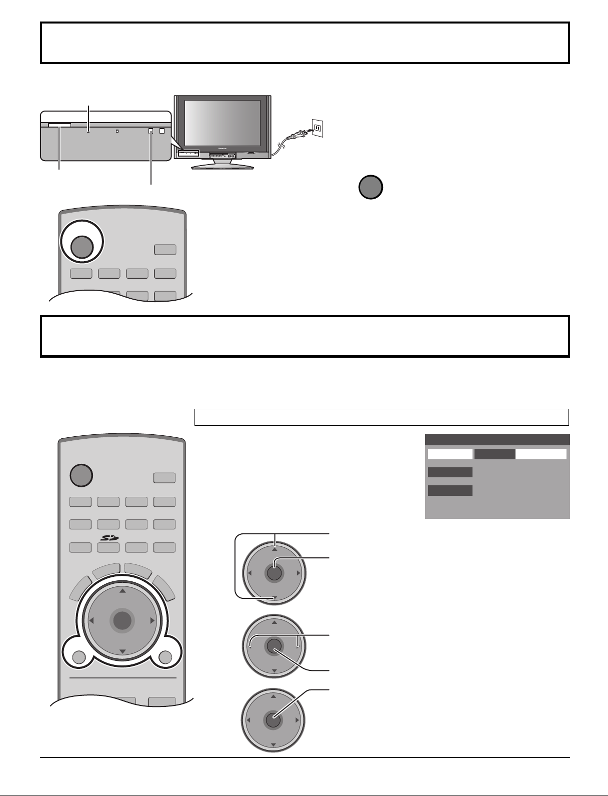
POWER
Power ON / OFF
Power indicater
Power on : Red
Power off : No Light
PC CARD
TV/VIDEOOKMENU VOLUME CHANNEL
S VIDEOHPJ VIDEO
Connect the plug to the wall outlet.
1
ELECT
-
AUDIO-R
L
INPUT 3
POWER button
Remote control sensor
2
Press to turn the TV on or off.
Note:
The TV will consume some power as long as the
power cord is inserted into the wall outlet.
First Time Setup
For your convenience, First Time Setup menu will be displayed on screen when the set is turned on for the first time. If
needed, follow the menus and procedures displayed on-screen for setting up the features.
You can also make the settings in Setup menu (see pages 30-32).
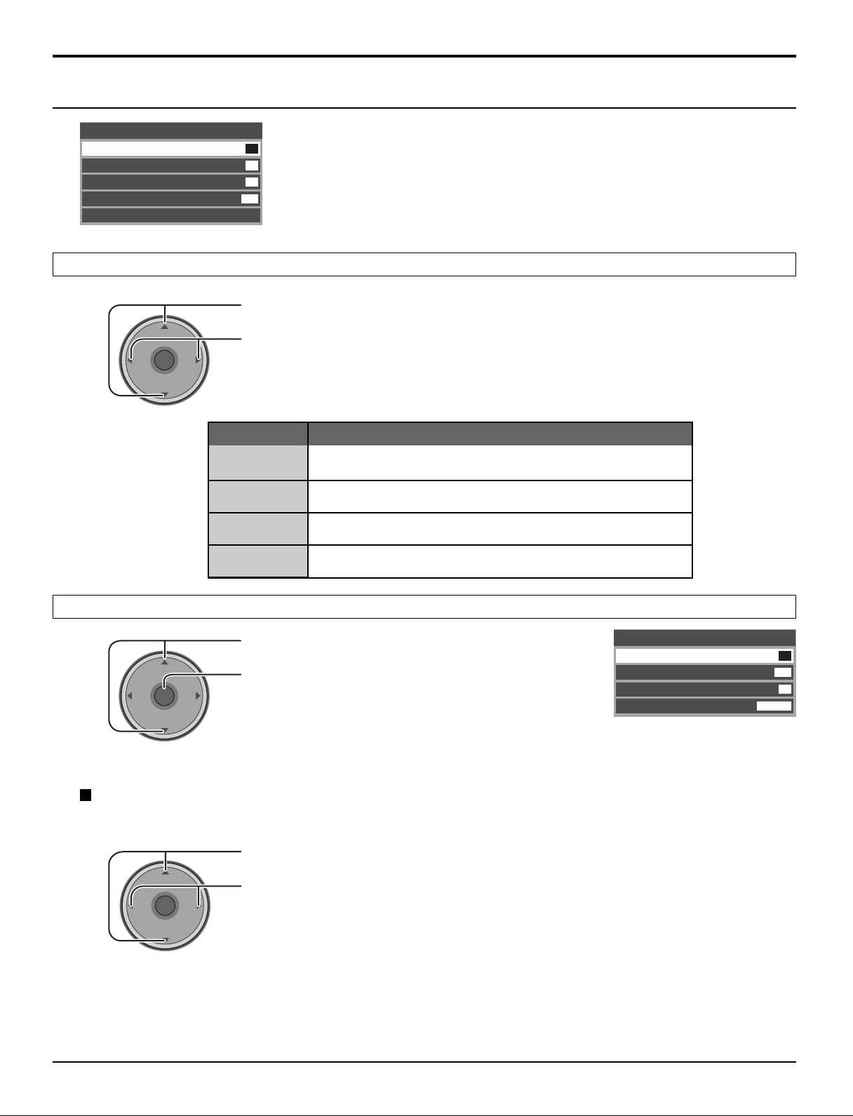
Input Setup
Select the configuration of RF input depending on
the signal source.
First Time Setup
Input Setup
Setting
Cable/Antenna
Auto Scan
Language
1
2
VOL
CH
OK
VOL
CH
CH
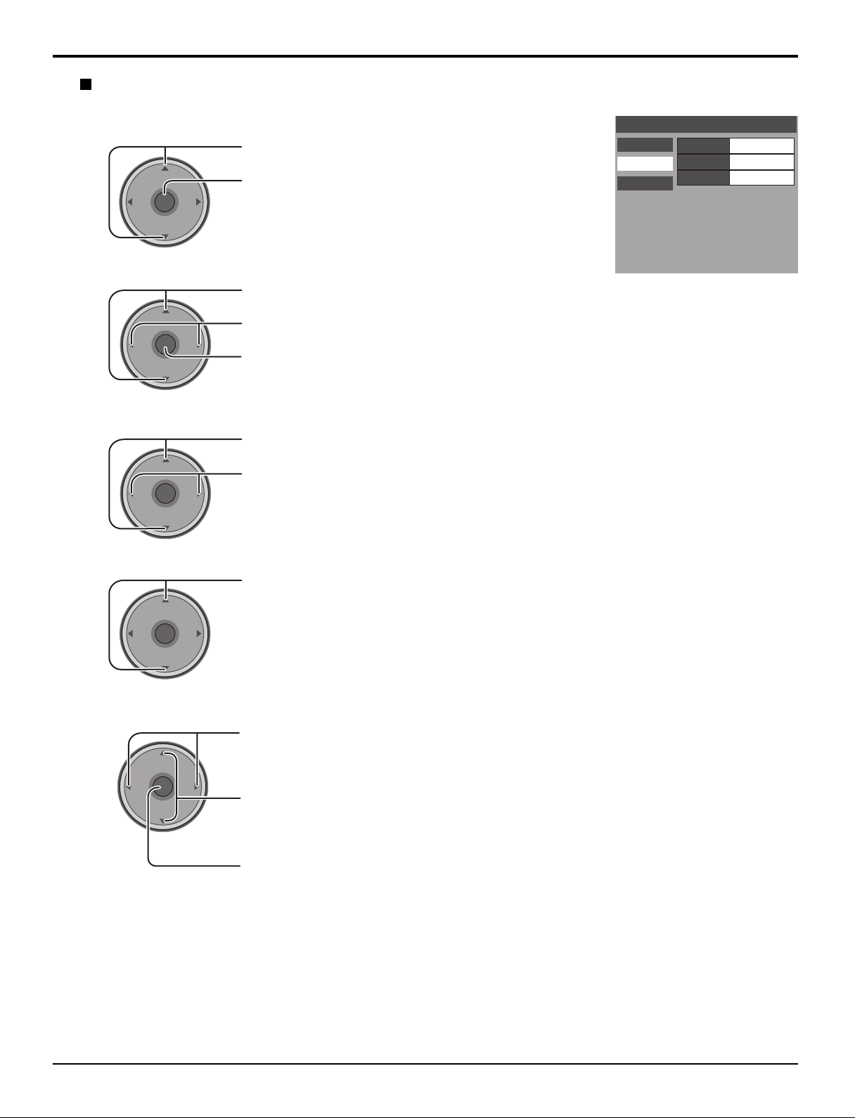
Press to select Input Setup.
Press to enter the sub-menu field.
Press to select Cable Only, Cable/Antenna
OK
VOL
3
VOL
VOL
CH
or Antenna Only.
Press to enter your selection.
Press to start the Auto Scan.
CH
OK
VOL
CH
All available channels with a signal will be
programmed into memory.
15
Page 16
First Time Setup
MENU
EXIT
First Time Setup
Input Setup
Auto Scan
Language
English
Setting
CH
VOL
CH
VOL
OK
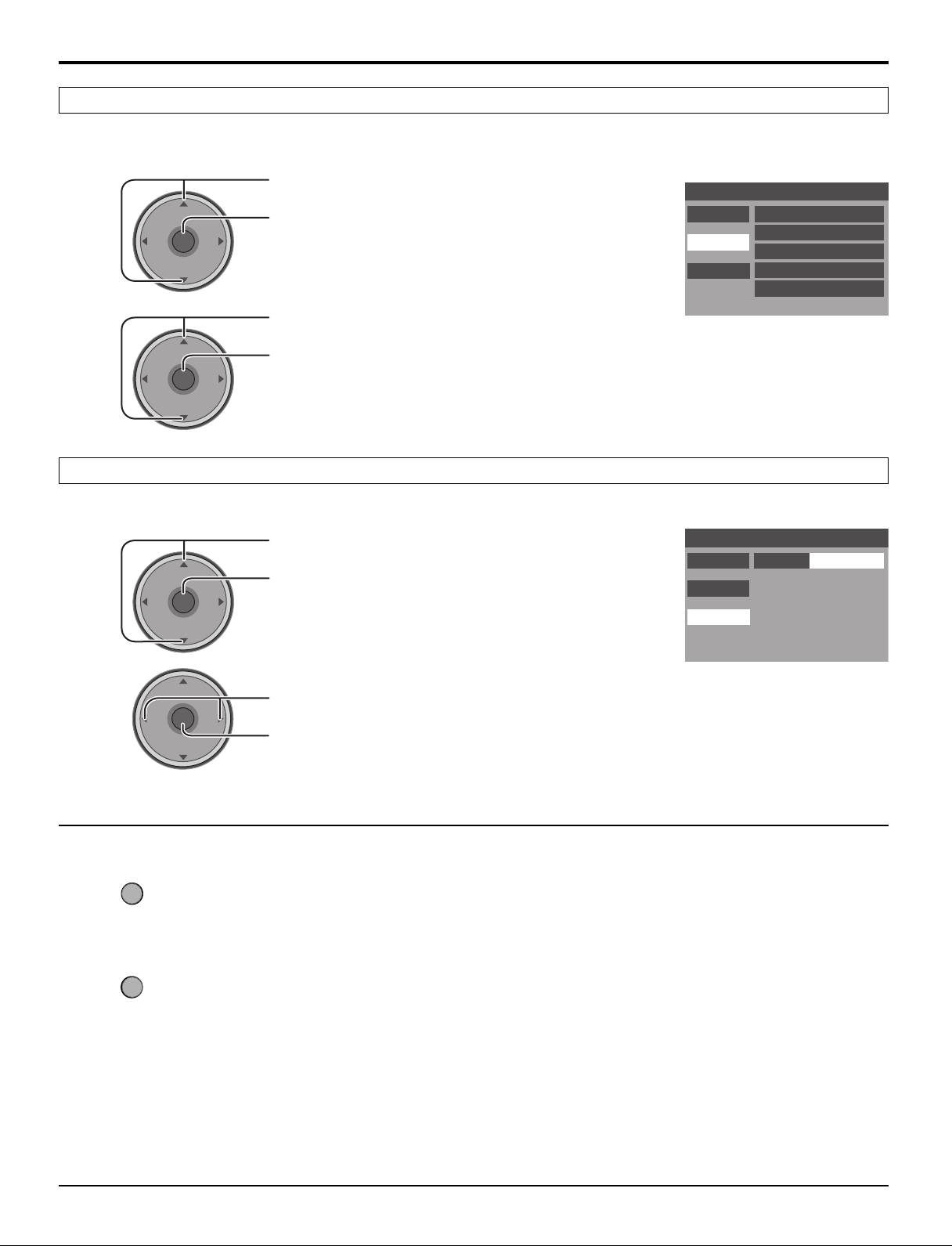
Auto Scan
This feature allows you to selectively auto scan channels.
You can scan All, Analog only channels or Analog & Digital channels.
1
2
VOL
VOL
CH
OK
VOL
CH
CH
OK
VOL
CH
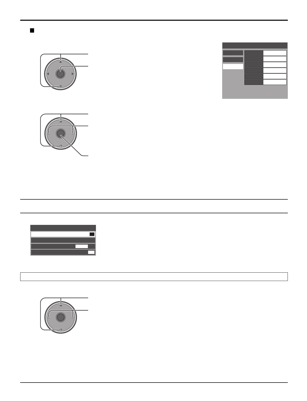
Press to select Auto Scan.
Press to enter the sub-menu field.
Press to select the sub-menu.
Press to start Auto Scan.
After Auto Scan is completed, the TV tunes to the first channel found during Auto Scan.
Language
Select the On screen Display language.
1
Press to select Language.
Press to enter the sub-menu field.
First Time Setup
Input Setup Scan All
Auto Scan
Language
Antenna (A) Analog
Antenna (A) Analog & Digital
Antenna (B) Analog
Antenna (B) Analog & Digital
16
2
VOL
CH
OK
VOL
CH
Press to select English, Spanish or French.
Press to enter your selection.
To return to the previous menu
Press to return.
To exit the menu
Press to return to normal picture.
Notes:
• If the EXIT button is pressed at anytime during Auto Scan, Auto Scan will be cancelled and the TV will return to the
First Time Setup menu.
• If a CableCARDTM is present during the First Time Setup and Antenna (A) is set to cable, Antenna (A) will not be
scanned due to the CableCARDTM providing the channel map.
Page 17
Watching TV programs
MENU
R-TUNE PROG
EXIT
VCR DVD
RCVR
LIGHT
A -ANTENNA - B
SAP
1 2 3
4 5 6
7 8
0
9
AUX
A
S
P
E
C
T
M
U
T
E
R
E
C
A
L
L
STOP
PAUSE
TV/VCR
REC
CH
VOL
CH
VOL
OK
POWER
TV/VIDEO
TV
FF
SPLIT
PLAY
DTV
DBS/CBL
S
L
E
E
P
TV
OPEN/CLOSE
SPLIT CH
DVD/VCR CH
SWAP
REW
POWER
TV
POWER
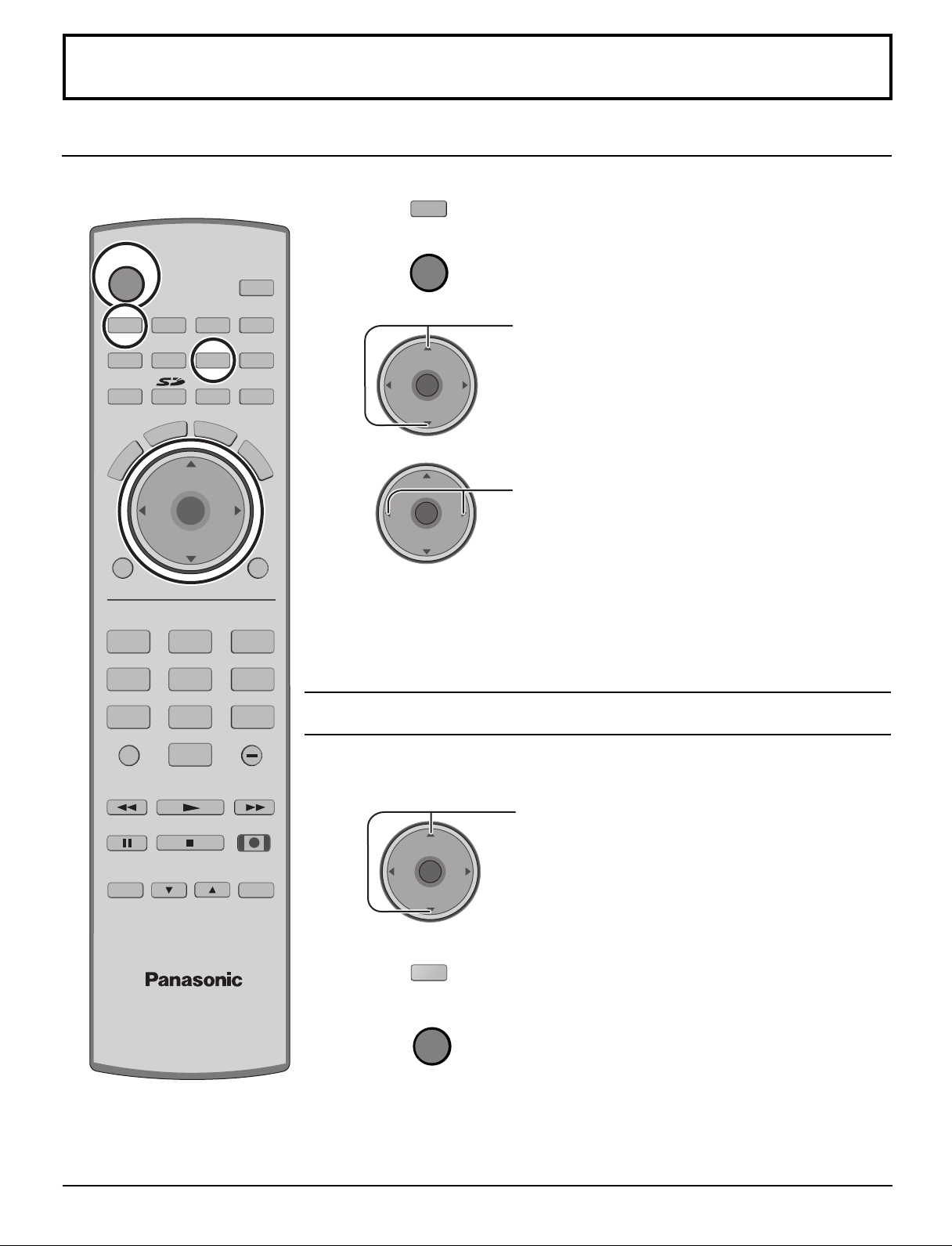
VHF and UHF
1
Press to operate the TV set with the remote control.
2
Press to turn the TV on.
3
VOL
CH
OK
VOL
CH
Press to select desired channel.
4
CH
OK
VOL
VOL
CH
Notes:
• The channel number and volume level remain the same even after the TV is
turned off.
• Power consumption can be reduced if the volume level is lowered.
Press to select the desired volume level.
Cable TV
Make sure that registration with cable TV provider and connection of equipment are
completed.
1
CH
OK
VOL
2
VOL
CH
DBS/CBL
3
Notes:
• The remote control code number is set for Panasonic products.
•To operate other manufacturer’s product, see pages 50-55.
Press to select the TV channel 3 or 4.
Press to operate the cable box with the remote control.
Press to turn the cable box on.
Point the remote control toward the cable box.
17
Page 18
MENU
TV
POWER
R-TUNE PROG
VCR DVD
RCVR
LIGHT
TV/VIDEO
A -ANTENNA - B
SAP
1 2 3
4 5 6
7 8
0
9
AUX
A
S
P
E
C
T
M
U
T
E
R
E
C
A
L
L
STOP
PAUSE
TV/VCR
REC
CH
VOL
CH
VOL
OK
MENU EXIT
FF
SPLIT
PLAY
DTV
DBS/CBL
S
L
E
E
P
TV
OPEN/CLOSE
SPLIT CH
DVD/VCR CH
SWAP
REW
Menu Navigation
CH
VOL
CH
VOL
OK
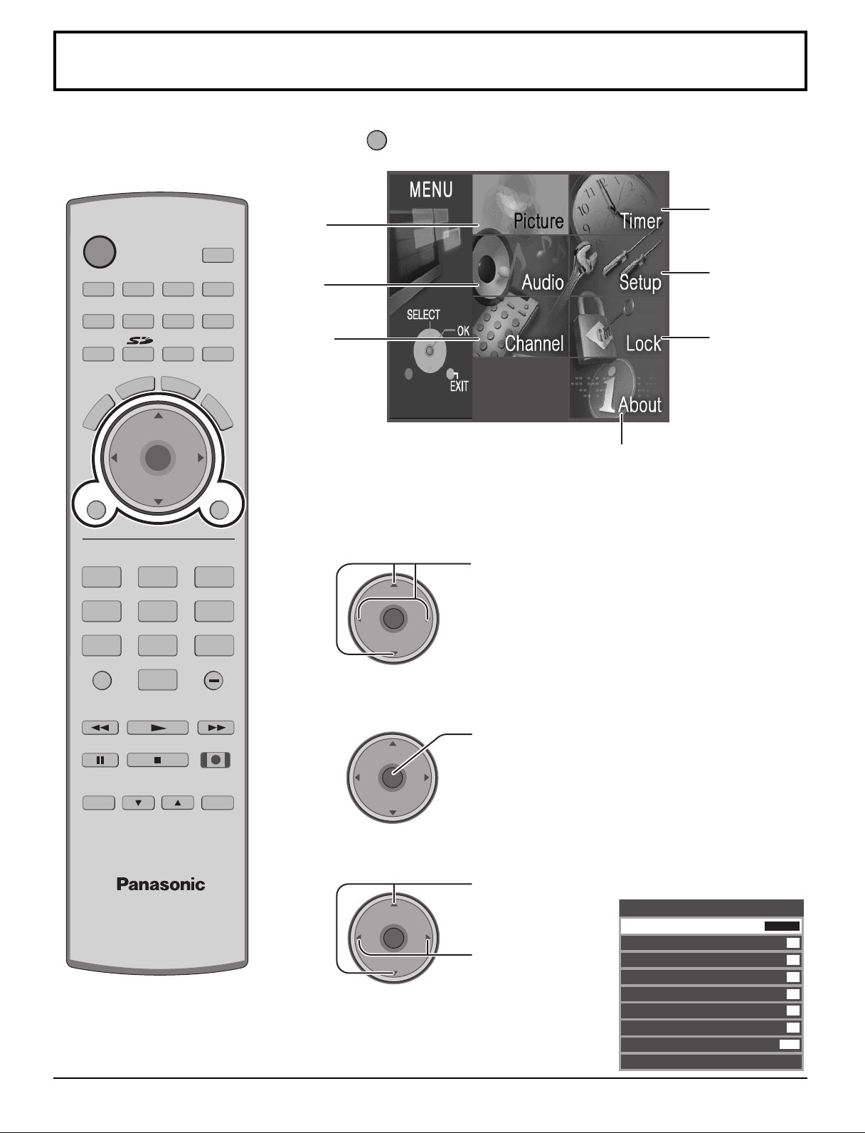
1
Press to display the Main menu.
Timer
Picture
(see page 27)
(see page 20)
Setup
Audio
(see page 30)
(see page 22)
Channel
(see page 24)
Lock
(see page 36)
About
The About screen displays
assorted information about the TV.
Please have this information when
calling Customer Care Center.
2
Press to select the menu.
18
4
3
VOL
VOL
Press to enter the sub-menu field.
CH
OK
VOL
CH
Press to select
CH
VOL
OK
CH
the sub-menu.
Press to adjust
the sub-menu.
ex. Picture menu
Picture
Pic Mode
Back Light
Color
Tint
Brightness
Picture
Sharpness
Normal
Other Adjust
Vivid
63
31
31
31
63
42
Set
Page 19
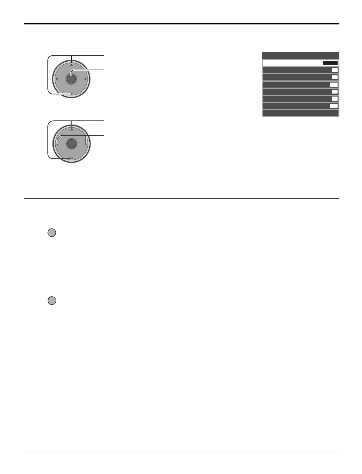
To select Other Adjust sub-menu
MENU
EXIT
Menu Navigation
2
1
VOL
VOL
CH
OK
VOL
CH
CH
OK
VOL
CH
Press to select Other Adjust.
Press to display the sub-menu.
Press to select the sub-menu.
Press to adjust or activate the sub-menu.
To return to the previous menu
Other Adjust
Color
Temp
AI Picture
Color Enhance
Video NR
3D Y/C Filter
Color Matrix
MPEG NR
Advanced Adjust
Cool
On
On
Off
On
SD
Off
Press to return.
To exit the menu
Press to return to normal picture.
19
Page 20
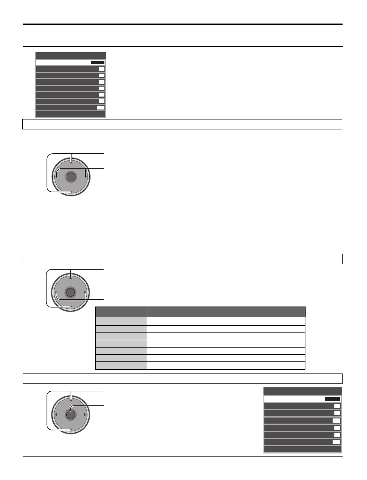
Menu Navigation
Picture
Picture
Pic Mode
Back Light
Color
Tint
Brightness
Picture
Sharpness
Normal
Other Adjust
Pic Mode
Lets you choose the pre-set picture mode that best suits the program you are viewing. This feature also affects Color Temp
setting (see page 21).
Vivid
63
31
31
31
63
42
Set
Press to select Pic Mode.
Notes:
VOL
CH
OK
VOL
CH
Press to select the picture mode.
Vivid (default): Provides enhanced picture contrast and sharpness for viewing in a well-
•
Standard : Recommended for normal viewing conditions with subdued room lighting.
•
Cinema : For watching movies in a darkened room. It provides a soft, film-like
•
Custom : You can customize the picture settings to suit your preference. (see page
•
Auto : Automatically senses the ambient light conditions and adjusts the
•
lit room.
picture.
21, Advanced Adjust)
brightness and gradation accordingly, to optimize contrast.
• Each mode has its own picture settings (Back Light, Color, Tint, Brightness, Picture and Sharpness).
• The Custom setting is stored for TV, VIDEO1, VIDEO2, VIDEO3, COMPONENT1, COMPONENT2, HDMI and Card
operations mode individually.
Back Light / Color / Tint / Brightness / Picture / Sharpness / Normal
Press to select the sub-menu.
CH
VOL
VOL
OK
CH
Press to adjust the sub-menu.
Item
Back Light
Color
Tint
Brightness
Picture
Sharpness
Normal
Adjusts luminance of the back light.
Adjusts desired color intensity.
Adjusts natural flesh tones.
Adjusts dark areas of picture.
Adjusts white areas of picture.
Adjusts clarity of outline detail.
Resets all picture adjustments to factory default settings.
Explanations
Other Adjust
20
VOL
Press to select Other Adjust.
CH
OK
VOL
CH
Press to display the sub-menu.
Other Adjust
Color
Temp
AI Picture
Color Enhance
Video NR
3D Y/C Filter
Color Matrix
MPEG NR
Advanced Adjust
Cool
On
On
Off
On
SD
Off
Page 21
Menu Navigation
CH
VOL
CH
VOL
OK
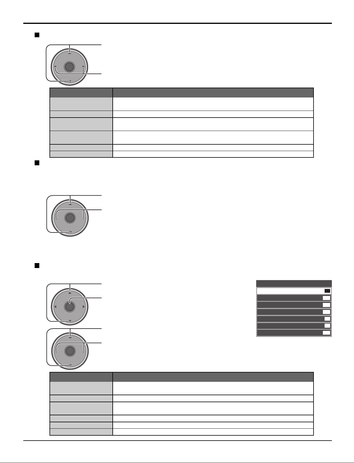
Color Temp (temperature) / AI Picture / Color Enhance / Video NR / 3D Y/C Filter / MPEG NR
Press to select the sub-menu.
CH
VOL
Color Temp
(temperature)
AI Picture
Color Enhance
Video NR
3D Y/C Filter
MPEG NR
VOL
OK
CH
Item
Press to adjust or activate the sub-menu.
Explanations
To increase or decrease Warm (red) and Cool (blue) colors to suit personal
preferences.
Displays black and white more vividly when turned On.
To increase the color reproduction range with natural color gradation and
highly delicate hues.
Reduces noise, commonly called snow. Leave off when receiving a strong
signal.
Minimizes noise and cross-color in the picture.
Noise unique to DVD, STB, etc. will be reduced.
Color Matrix
Displays 480p input signals in natural color from digital video sources connected to COMPONENT VIDEO INPUT (Y,
PB, PR) terminals.
Select HD or SD to automatically adjust color parameters for HD (high definition) or SD (standard definition).
Press to select Color Matrix.
Press to select SD or HD.
SD : When the input signal is a normal TV system (NTSC).
•
HD : When the input signal is a High-Definition system (ATSC).
•
Notes:
• This feature is available only with 480p signal and not available with regular TV (NTSC) program.
•
When viewing a non-standard DTV signal format, you can change color parameters manually for the best picture quality.
Advanced Adjust
This feature is available only when you selected Custom in Pic Mode.
1
CH
OK
VOL
VOL
CH
2
CH
OK
VOL
Edge Trans.
Gray Emph.
Gamma Adj.
Black Extension
White Char Corr
Normal
VOL
CH
Item
Press to select Advanced Adjust.
Press to display the sub-menu.
Press to select Adv. Adjust.
Press to select On.
On : Available to select and adjust the sub-menu.
•
Off : Not available to select and adjust the sub-menu.
•
Explanations
Improves edges in the background to reduce overshooting and improve the
sense of depth.
Emphasizes the sharpness in density of many color differences.
Increases the brightness of the center ranges to improve detail and contrast
in dark scenes.
Contrast level will be improved.
It makes white characters brighter.
Resets all advanced adjustments to factory default setting.
Advanced Adjust
Adv.
Adjust
Edge Trans.
Gray Emph.
Gamma Adj.
Black Extension
White Char Corr
Normal
On
Mid
Mid
Mid
8
8
Set
21
Page 22
Menu Navigation
Audio
Audio
Bass
Treble
Balance
Normal
Other Adjust
Bass / Treble / Balance / Normal
7
7
31
Set
Press to select the sub-menu.
CH
OK
VOL
CH
Other Adjust
CH
OK
VOL
CH
VOL
VOL
Press to adjust or activate the sub-menu.
Item
Bass
Treble
Balance
Normal
Increase or decrease the bass response.
Increase or decrease the treble response.
Emphasize the left / right speaker volume.
Reset Bass, Treble and Balance adjustments to factory
default settings.
Explanations
Press to select Other Adjust.
Press to display the sub-menu.
Other Adjust
AI Sound
Surround
Equalizer
HDMI ln
On
Off
On
Auto
AI Sound
Equalize overall volume level across all channels.
Press to select AI Sound.
VOL
CH
OK
VOL
CH
Press to select On or Off.
22
Page 23
Surround
Enhances audio response when listening to stereo.
Press to select Surround.
Menu Navigation
VOL
CH
OK
VOL
CH
Press to select On or Off.
On : Surround on
•
Off : Surround off
•
Equalizer
This feature makes voice sound clear.
Press to select Equalizer.
VOL
CH
OK
VOL
CH
Press to select On or Off.
On : Equalizer operates normally.
•
Off : Equalizer off.
•
HDMI In
When using HDMI (see page 13), this feature will let you switch between Analog Input and Digital Input.
Press to select HDMI In.
VOL
CH
OK
VOL
CH
Press to select the mode.
Auto : Automatically selects Analog / Digital signal.
•
Digital : Digital Input only.
•
Analog : Analog Input only.
•
23
Page 24
CH
VOL
CH
VOL
OK
Menu Navigation
Favorite
Surf Mode
All Channels
RF Input
Antenna (A)
Channel
A: 2
The maximum is 16 favorite channels.
Channel
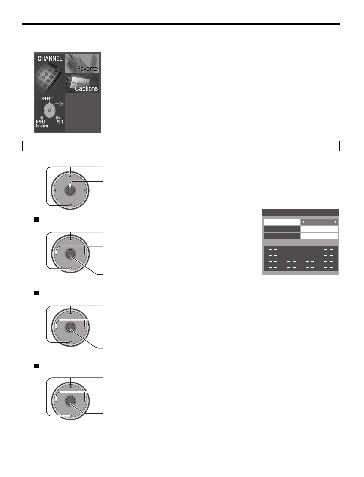
Favorite
Allows you to create a Favorite channel list from Antenna (A) or Antenna (B).
Press to select Favorite.
VOL
Surf Mode
RF Input
VOL
CH
OK
VOL
CH
Press to display the sub-menu.
Press to select Surf Mode.
Press to select Favorites or All Channels.
Press to enter your selection.
Press to select RF Input.
CH
OK
VOL
CH
Press to select Antenna (A) or Antenna (B).
Press to enter your selection.
Channel
CH
OK
VOL
24
CH
Press to select Channel.
Press to select the channel.
VOL
Press to add the channel.
To delete the channel, press again while the channel number is displayed.
Repeat step 2, up to 16 favorite channels.
Page 25
Menu Navigation
1 2 3
4 5 6
7 809
CH
VOL
CH
VOL
OK
Captions
To enter preset and manual labels to desired stations. Also to enter input labels to video inputs.
Press to select Captions.
VOL
CH
OK
VOL
CH
Press to display the sub-menu.
Preset Labels
To enter channel numbers for popular TV stations.
1
2
VOL
CH
OK
VOL
CH
Press to select Preset Labels.
Press to enter the sub-menu field.
Press to select RF Input.
Press to select Antenna (A) or Antenna (B).
Press to enter your selection.
Captions
Preset Labels
Manual Labels
Input Labels
RF Input
ABC
CBS
FOX
NBC
PBS
CNN
ESPN
HBO
Antenna (A)
3
4
5
VOL
VOL
CH
OK
VOL
CH
CH
OK
VOL
CH
Press to select the desired preset caption.
Select the channel (refer to your local TV guide).
Press to enter your selection.
To delete a channel number, while highlighted press repeatedly until all numbers are
removed, then press OK button.
Note:
Only an input with signal will be selectable.
25
Page 26
Menu Navigation
Manual Labels
To enter numbers and captions manually.
1
VOL
CH
OK
VOL
CH
Press to select Manual Labels.
Press to enter the sub-menu field.
Captions
Preset Labels
Manual Labels
Input Labels
RF Input
Channel
Caption
Antenna (A)
A: 2
3
4
2
VOL
VOL
VOL
Press to select RF Input.
CH
OK
VOL
Press to select Antenna (A) or Antenna (B).
Press to enter your selection.
CH
Press to select Channel.
CH
OK
VOL
CH
Press to select the available channel number.
Press to select Caption.
CH
OK
VOL
CH
5
VOL
CH
OK
VOL
Press to select the character position.
Press to select the character (refer to your local TV guide).
CH
Repeat until all characters are added, up to 7 characters can be added for each channel.
To delete the Channel Caption, press until no character is displayed.
Press to enter your selection.
Note:
Only an input with signal will be selectable.
26
Page 27
Input Labels
To label video input connections for on-screen display.
1
VOL
CH
OK
VOL
CH
Press to select Input Labels.
Press to enter the sub-menu field.
Menu Navigation
Captions
Preset Labels
Manual Labels
Input Labels
Component 1
Component 2
HDMI
Video 1
Video 2
Video 3
2
Timer
Timer
Sleep
Timer
Clock Set
Day Set
VOL
Press to select the video input.
CH
OK
VOL
Press to select the preset input label.
To delete Input labels, press until no label is displayed, and then press OK button to enter
your selection.
CH
To skip the input, select ‘‘SKIP’’. The input will be skipped when you press TV/VIDEO.
Press to enter your selection.
No
- -
- - : - -
- - -
Sleep
VOL
Press to select Sleep.
CH
OK
VOL
Press to select the desired sleep time (No, 30, 60 or 90).
To turn off the timer, select No.
To confirm the remaining time, press RECALL button (see page 8).
CH
27
Page 28
Menu Navigation
Timer
Set the time in Clock Set (see page 29) before setting Timer.
Select timer to turn the TV on and off at selected times and on selected days.
Press to select Timer.
CH
OK
VOL
VOL
CH
Day
CH
OK
VOL
VOL
CH
On Time / Off Time
Press to display the sub-menu.
Press to select Day.
Press to select appropriate day setting.
Timer
Sleep
Timer
Clock Set
Day Set
Timer
Day
On Time
Off Time
Set
No
AM12 : 01
MON
MON-FRI
7 : 10 AM
8 : 10 PM
Yes
1
2
3
VOL
VOL
VOL
CH
OK
VOL
CH
CH
OK
VOL
CH
CH
OK
VOL
CH
Press to select On Time or Off Time.
Press to enter the time field.
Press to select the hour (AM or PM) or the minutes position.
Press to set the hour (AM or PM) and the minutes.
Press to enter your selection.
Notes:
• The TV automatically turns Off after 90 minutes when turned On by the Timer. It will be cancelled if the Off Time is
selected or if a key is pressed.
• When the power to the TV set is disrupted due to a power outage or similar problem, the timer will be deactivated
and the TV will be in standby mode even after power is restored.
28
Set
VOL
Press to select Set.
CH
OK
VOL
CH
Press to select Yes or No.
Page 29
To activate the Timer
Select the channel and turn off the TV.
Clock Set
Menu Navigation
1
2
3
VOL
VOL
VOL
Press to select Clock Set.
CH
OK
VOL
CH
Press to enter the time field.
Press to select the hour (AM or PM) or the minutes position.
CH
OK
VOL
CH
CH
OK
VOL
CH
Press to set the hour (AM or PM) and the minutes.
Press to enter your selection.
Day Set
Set the day of the week.
CH
OK
VOL
VOL
CH
Press to select Day Set.
Press to select the day of the week.
29
Page 30
Cable/Antenna
Program Channel
Input Setup Setting
Auto Scan
Manual Program
Signal Meter
Language
CH
VOL
CH
VOL
OK
Menu Navigation
Setup
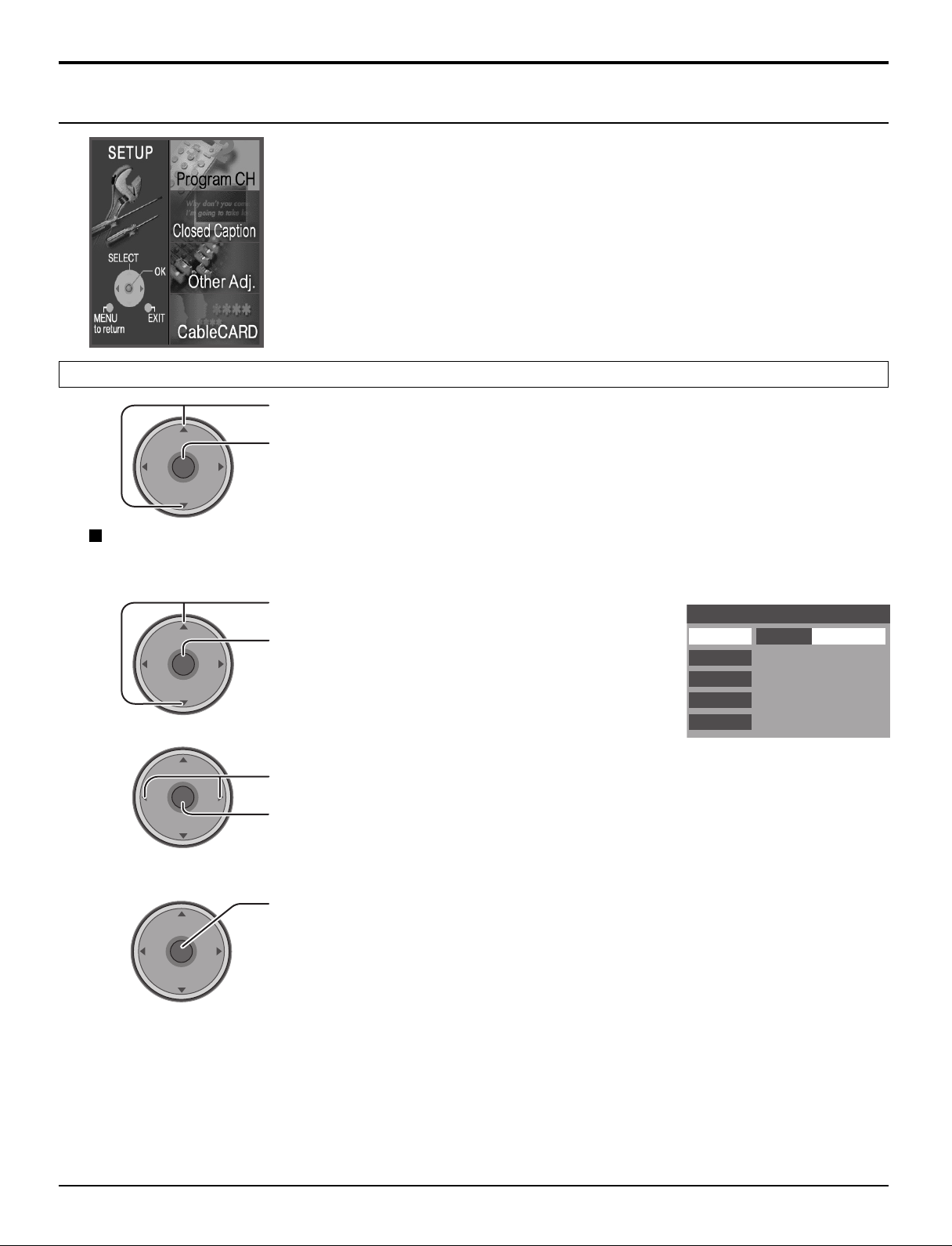
Program CH
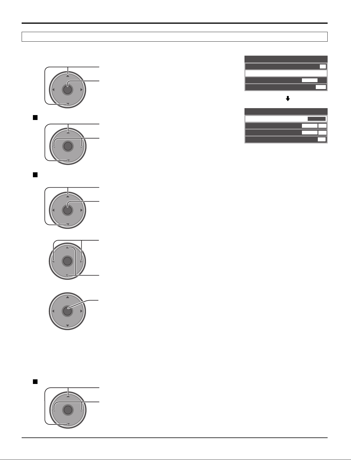
Press to select Program CH.
VOL
CH
OK
VOL
CH
Press to display the sub-menu.
Input Setup
Lets you specify the antenna mode (Cable only, Cable/Antenna or Antenna only).
1
Press to select Input Setup.
Press to enter the sub-menu field.
2
VOL
CH
OK
VOL
CH
Press to select the antenna mode.
Press to enter your selection.
The confirmation message appears.
3
Notes:
• Auto Scan is necessary when you select the input signal for the first time or whenever you change the antenna
• If CableCARDTM is not inserted, the Auto Scan performs Scan All.
• When CableCARDTM is inserted and Cable only is selected, Auto Scan will be skipped.
• When CableCARDTM is inserted and Cable/Antenna is selected, Antenna (B) Analog & Digital Auto Scan will be
• In order to manually select Antenna B from the remote, Auto Scan must first be performed.
30
CH
OK
VOL
CH
configuration.
performed.
Press to start Auto Scan.
All available channels with a signal will be programmed into memory.
VOL
Page 31

CH
VOL
CH
VOL
OK
Language
Input Setup
Antenna (A)
Auto Scan
RF Input
A: 1
A: 2
Channel Add
Channel Del
Manual Program
Signal Meter
Program Channel
Menu Navigation
Auto Scan
Automatically scans all available channels, Antenna (A) Analog, Antenna (A) Analog & Digital, Antenna (B) Analog, and
Antenna (B) Analog & Digital.
1
2
VOL
VOL
CH
OK
VOL
CH
CH
OK
VOL
CH
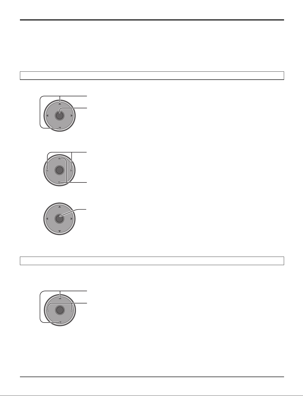
Press to select Auto Scan.
Press to enter the sub-menu field.
Press to select the sub-menu.
Press to start Auto Scan.
After Auto Scan is completed, press MENU to return to the previous screen.
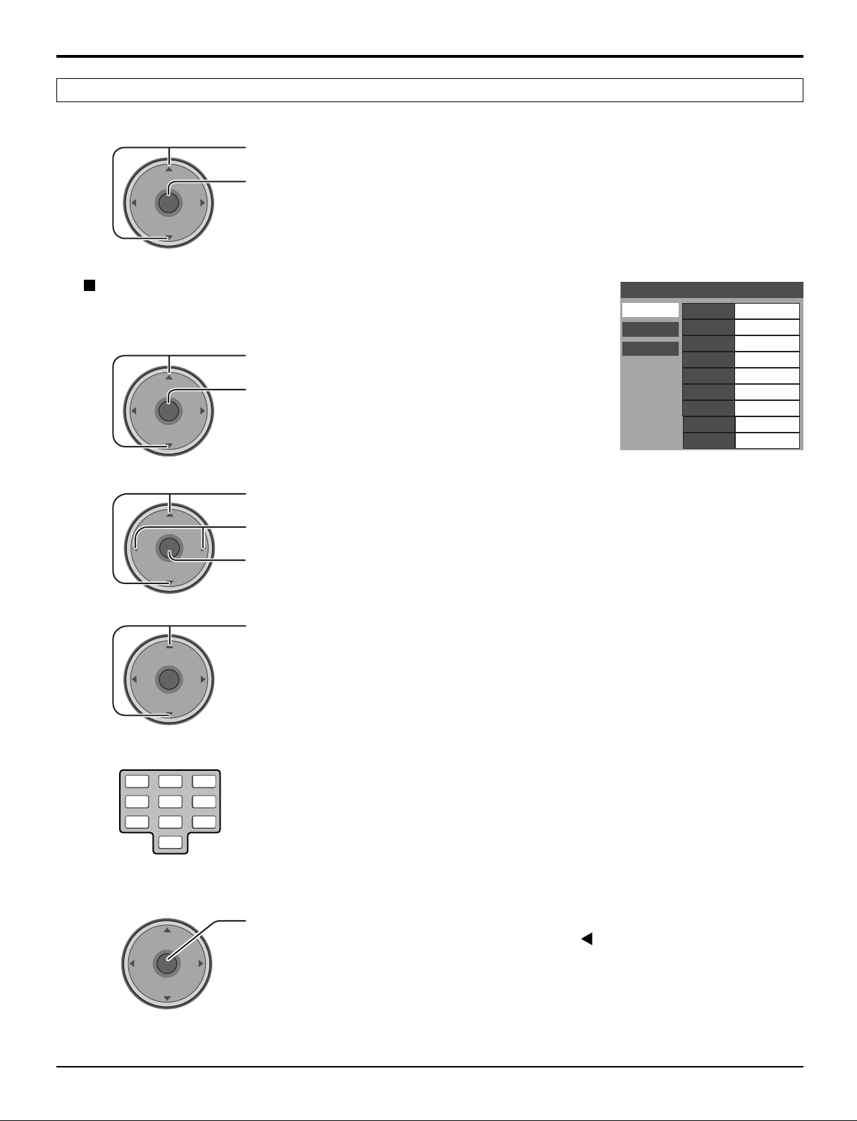
Manual Program
To add or delete channels from either channels list (A/B) manually.
1
Press to select Manual Program.
Program Channel
Input Setup Scan All
Auto Scan
Manual Program
Signal Meter
Language
Antenna (A) Analog
Antenna (A) Analog & Digital
Antenna (B) Analog
Antenna (B) Analog & Digital
2
3
4
CH
OK
VOL
CH
CH
OK
VOL
CH
CH
OK
VOL
CH
Press to enter the sub-menu field.
Press to select RF Input.
Press to select Antenna (A) or Antenna (B).
VOL
Press to enter your selection.
Press to select Channel Add or Channel Del.
VOL
Press to select the channel.
VOL
Press to add or delete the channel.
31
Page 32

Menu Navigation
Signal Meter
(For digital channels only)
Displays the signal strength of the ATSC digital channel in either Antenna (A) or Antenna (B).
1
2
Language
VOL
VOL
Press to select Signal Meter.
CH
OK
VOL
CH
CH
Press to enter the sub-menu field.
Program Channel
Input Setup
Auto Scan
Manual Program
Signal Meter
Language
RF Input
Channel
Signal Strength : 96%
Peak : 96%
Antenna (B)
B: 26-3
Press to select the channel.
OK
VOL
CH
Press to display the Signal Strength.
The color of the signal bar usually indicates the strength of the received signal.
Green - Adequate signal for a good reception.
Yellow - Poor signal strength.
Red - Very poor signal strength.
Select the On screen Display language.
1
2
VOL
VOL
CH
OK
VOL
CH
CH
OK
VOL
CH
Press to select Language.
Press to enter the sub-menu field.
Press to select English, Spanish or French.
Press to enter your selection.
Program Channel
Input Setup Setting
Auto Scan
Manual Program
Signal Meter
Language
English
32
Page 33

Menu Navigation
Closed Caption
The television includes a built-in decoder that is capable or providing a visual display of the audio portion. The program
viewed must provide Closed Captioning (CC) for the television to display it.
Press to select Closed Caption.
VOL
CH
OK
VOL
CH
Press to display the sub-menu.
CC Mode
Closed Caption
1
2
VOL
VOL
Press to select CC Mode.
CH
OK
VOL
CH
CH
VOL
OK
CH
Press to enter the sub-menu field.
Press to select the setting.
Off : Recommended mode when Closed Caption is not being used.
•
On : To display Closed Captions.
•
On Mute : To display Closed Captions when audio is muted by pressing
•
CC Mode
Analog
Digital
Setting
Off
the MUTE button.
Notes:
• The closed caption is not displayed when you use HDMI connection.
• When displaying or recording an analog channel program on a connected equipment, select the closed caption On/
Off setting on the connected equipment. The TV’s CC Mode setting does not affect the analog channel output
signal.
• When displaying or recording a digital channel program on a connected equipment, set the TV’s CC Mode setting to
Off and select the closed caption On/Off setting on the connected equipment. The digital closed captions will overlap
if the closed caption setting is On on both the TV and the connected equipment.
Analog
Lets you choose the closed caption service of Analog broadcasting.
1
2
VOL
CH
OK
VOL
CH
Press to select Analog.
Press to enter the sub-menu field.
Press to select the setting.
CC1 : For video related information that can be displayed (up to 4 lines of
•
script on the screen, where it does not disturb the relevant parts of the
picture). Script can be in any language.
CC2/CC3/CC4 : Other modes used for video related information.
•
T1 : Blanks out a large portion of the picture on the television screen, and
•
displays program guide or any other information currently being
transmitted.
T2/T3/T4 : Other modes that display information and blank out a large portion of
•
the picture of theTV screen.
Press to enter your selection.
Closed Caption
CC Mode
Analog
Digital
Service
CC1
33
Page 34

Menu Navigation
Digital
The Digital Closed Caption menu lets you configure the way you choose to view the digital captioning.
1
2
VOL
VOL
Press to select Digital.
CH
OK
VOL
CH
Press to enter the sub-menu field.
Closed Caption
CC Mode Primary
Analog
Digital
Service
Font
Size
Style
Colors
Reset
Sample CC Text
Automatic
Automatic
Automatic
Press to select the sub-menu.
CH
OK
VOL
CH
Press to select the setting.
Service : Primary, Secondary, Service 3, Service 4, Service 5, Service 6
•
Font :
•
Automatic, Default, Mono-serif, Pro-serif, Mono, Prop, Casual, Cursive,
Small Caps
Size : Automatic, Normal, Small, Large
•
Style : Automatic, None, Raised, Depressed, Uniform, Drop Shadow
•
Colors : Foreground ....... The color of the font (Automatic, Black, White, Red,
•
Green, Blue, Yellow, Magenta, Cyan)
Fore Opacity ..... The opacity of the font (Automatic,Transparent,
Translucent, Solid, Flashing)
Background ...... The color of the text box (Automatic, Black, White,
Red, Green, Blue, Yellow, Magenta, Cyan)
Back Opacity .... The opacity of the text box (Automatic, Transparent,
Translucent, Solid, Flashing)
Outline .............. The color of the outline of the dropshadow (if selected
under style)(Automatic, Black, White, Red, Green, Blue,
Yellow, Magenta, Cyan)
Reset : Reset the Digital CC settings.
•
34
3
VOL
CH
OK
VOL
CH
Press to enter your selection.
Page 35

Other Adjust
Menu Navigation
1
2
VOL
VOL
Press to select Other Adj.
CH
OK
VOL
CH
Press to display the sub-menu.
Press to select the sub-menu.
CH
VOL
OK
CH
Press to adjust or activate the sub-menu.
Other Adjust
Auto Power On
Power Save
Zoom Adjust
Auto Power On (Set or Off)
Select Set to power up the TV at the same time as the cable box or other connected components.
Power Save (Std. or Saving)
Off
Std.
Suppress the luminous level of the TV to reduce power consumption.
Zoom Adjust
Adjust the Zoom position.
It works when Aspect mode is Zoom.
Size : Adjust the vertical size.
•
V-Position : Adjust the vertical position.
•
CableCARD
TM
Zoom Adjust
Size
V-Position
Normal
4
0
Set
This menu provides information when a CableCARDTM is inserted into the CableCARD slot (see page 14).
Notes:
• If CableCARDTM is not inserted and you access the CableCARD Info, the message “Cable Module Not Present” appears.
•To receive the features offered by your cable company, you may have to subscribe to those services. Contact your cable
company regarding availability of the CableCARDTM. The CableCARDTM is required to receive premium digital services
(where available) through the cable input. You may also be able to order call-ahead pay-per-view events.
35
Page 36

Menu Navigation
1 2 3
4 5 6
7 809
Lock
When entering Lock menu for the first time, New Password setting screen is displayed.
Create a 4-digit password to enter the Lock menu.
Password
New Password
- - - -
Enter a 4-digit password.
Notes:
• Use a code that is easy to remember and record it in a safe place.
• If Always is selected in How Long? (see page 39) and you forget your secret code,
the TV must be serviced by a qualified technician to clear the Lock setup.
From the second time, enter the Password you set to display the sub-menu.
Blocking messages
Various Blocking messages are displayed on-screen depending upon the type of blocking you have selected in the Lock
menu.
Note:
Entering the password will override the block condition. However, the ratings selection will be retained.
Message
Possible cause
Video Inputs Locked.
Channel Locked.
Press OK to enter password.
Rating Limit Exceeded.
Press OK to enter password.
Game Lock is selected.
Channel Lock is selected.
The rating level is exceeded.
Lock Set
Select Lock Set to prevent viewing video games, VCR tapes, channels and Video modes.
Press to select Lock Set.
CH
OK
VOL
Mode
VOL
VOL
CH
Press to display the sub-menu.
Press to select the setting.
Off : Turns off Lock set functions.
•
Lock All : All channels are locked regardless of the
CH
OK
VOL
CH
•
rating level.
Game Lock : Locks out CH 3, 4 and Video inputs.
•
Channel Lock:
•
Locks out specific analog and digital channels.
Password is required to view any of the locked
channels.
Lock Set
Mode
Off
36
Press to enter your selection.
Page 37

CH
VOLCHVOL
OK
Channel Lock
CH
OK
VOLCHVOL
RF Input
Select either Antenna (A) or Antenna (B).
1
CH
OK
VOLCHVOL
Press to select Channel Lock.
Press to display the sub-menu.
Press to select RF Input.
Menu Navigation
Channel Lock
RF Input Antenna (A)
Channel
The maximum is 4 locked channels.
A: 2
2
CH
OK
VOLCHVOL
Press to select the setting.
Press to enter your selection.
Channel
Select up to four (4) channels to be blocked out. These channels will be blocked out regardless of the program rating.
1
2
CH
OK
VOLCHVOL
Press to select Channel.
Press to select the setting.
Press to enter your selection.
To clear the channel number from the list, select the channel number and press OK.
Block Program
This television incorporates V-CHIP technology to block the viewing of movies and television programs according to the
rating category. There are four (4) Content Advisory Categories: MPAA (Motion Picture Association of America) and TV
Parental Guidelines Ratings. These categories are used as guidelines for blocking the programs.
The default mode for the Lock category is the Unlocked state.
1
2
3
CH
OK
VOLCHVOL
CH
OK
VOLCHVOL
CH
OK
VOLCHVOL
Press to select Block Program.
Press to display the sub-menu.
Press to select the program.
MPAA : for U.S movie ratings
U.S.TV : for U.S TV program ratings
C.E.L.R : for Canadian English ratings
C.F.L.R : for Canadian French ratings
Press to enter the Mode field.
Press to select On or Off.
Press to enter your selection.
Block Program
MPAA
U.S.TV
C.E.L.R
C.F.L.R
Mode
NR
G
PG
PG-13
R
NC-17
Off
Viewable
Viewable
Viewable
Viewable
Viewable
Viewable
X
Viewable
4
CH
OK
VOLCHVOL
Press to highlight the desired rating level.
Press to change the rating limit to “Blocked” or “Viewable”.
Notes:
• The NR rating is independent of other ratings.
•
Placing a block on a specific age based rating level, the NR rating and any other more restrictive ratings will also be blocked.
37
Page 38

Menu Navigation
U.S. TV PROGRAMS RATINGS CHART
The TV Parental Guidelines has 7 levels of age-based ratings that can be selected. These 7 levels are split into 2 agebased groups:
Youth Age-based Ratings and Guidance Age-based Ratings. Some of these age-based ratings can also have contentbased ratings, denoted as D (Dialogue), L (Language), S (Sex) and V (Violence).
TV-NR
TV-Y
TV-Y7
TV-G
TV-PG
TV-14
TV-MA
FV
V
S
L
D
U.S. MOVIES RATINGS CHART
NR
G
PG
PG-13
R
NC-17
X
CANADIAN ENGLISH RATINGS CHART
E
C
C8+
G
PG
14+
18+
CANADIAN FRENCH RATINGS CHART
E
G
8 ANS+
13ANS+
16ANS+
18ANS+
Not Rated. See Customer Caution below.
All children. The themes and elements in this program are specifically designed for a very young audience,
including children from ages 2-6.
Directed to older children. Themes and elements in this program may include mild physical or comedic violence, or
may frighten children under the age of 7.
General audience. It contains little or no violence, no strong language, and little or no sexual dialogue or situations.
Parental guidance suggested. The program may contain infrequent coarse language, limited violence, some
suggestive sexual dialogue and situations.
Parents strongly cautioned. This program may contain sophisticated themes, sexual content, strong language and
more intense violence.
Mature audiences only. This program may contain mature themes, profane language, graphic violence, and explicit
sexual content.
FANTASY/CARTOON VIOLENCE
VIOLENCE
SEX
OFFENSIVE LANGUAGE
DIALOGUE WITH SEXUAL CONTENT
CONTAINS NO RATING (NOT RATED) AND NA (NOT APPLICABLE) PROGRAMS. Movie has not been rated or
rating does not apply.
GENERAL AUDIENCES. All ages admitted.
PARENTAL GUIDANCE SUGGESTED. Some material may not be suitable for children.
PARENTS STRONGLY CAUTIONED. Some material may be inappropriate for children under 13.
RESTRICTED. Under 17 requires accompanying parent or adult guardian.
NO ONE 17 AND UNDER ADMITTED.
ADULTS ONLY.
Exempt - Exempt programming includes: news, sports, documentaries and other information programming, talk
shows, music videos, and variety programming.
Programming intended for children under age 8. No offensive language, nudity or sexual content.
Programming generally considered acceptable for children 8 years and over. No profanity, nudity or sexual content.
General programming, suitable for all audiences.
Parental Guidance suggested. Some material may not be suitable for children.
Programming contains themes or content which may not be suitable for viewers under the age of 14. Parents are
strongly cautioned to exercise discretion in permitting viewing by pre-teens and early teens.
18+ years old. Programming restricted to adults. Contains constant violence or scenes of extreme violence.
Exempt - Exempt programming.
General - Programming intended for audience of all ages. Contains no violence, or the violence content is minimal
or is depicted appropriately.
8+ General - Not recommended for young children. Programming intended for a broad audience but contains light
or occasional violence. Adult supervision recommended.
Programming may not be suitable for children under the age of 13 - Contains either a few violent scenes or one or
more sufficiently violent scenes to affect them. Adult supervision strongly suggested.
Programming may not be suitable for children under the age of 16 - Contains frequent scenes of violence or
intense violence.
18+ years old. Programming restricted to adults. Contains constant violence or scenes of extreme violence.
Customer Caution
The V-Chip system that is used in this set is capable of blocking “NR” programs (non rated, not applicable and
none) per FCC Rules Section15.120(e)(2). If the option of blocking “NR” programs is chosen “unexpected and
possibly confusing results may occur, and you may not receive emergency bulletins or any of the following types of
programming:”
• Emergency Bulletins (Such as EAS messages, weather warnings and others)
• Locally originated programming • News • Political • Public Service Announcements • Religious • Sports
• Weather
38
Page 39

1 2 3
4 5 6
7 809
How Long?
The Lock settings remain for the selected duration.
Press to select How Long?.
CH
OK
VOL
Time
VOL
CH
Press to display the sub-menu.
Menu Navigation
How Long?
Time
The TV will remain locked for
the selected duration
12 hours
VOL
CH
Press to select 12 hours, 24 hours, 48 hours or Always.
OK
VOL
CH
Press to enter your selection.
Note:
When you select Always and you forget your secret code, the TV must be serviced by a qualified technician to clear
the Lock setup.
Password
You can change the password.
1
VOL
CH
OK
VOL
CH
Press to select Password.
Press to display the sub-menu.
Password
Change Password
- - - -
2
Enter a 4-digit password.
39
Page 40

TV/VIDEOOKMENU VOLUME CHANNEL
S VIDEOHPJ VIDEO
INPUT 3
L
-
AUDIO-R
ELECT
PC CARD
Card operations
This function lets you display Still images (JPEG) or Animated pictures (MPEG4) recorded by this unit or a digital camera
on a memory card when it is inserted in the proper card slot.
Inserting and removing a card
SD card slot
Label-side
upward
Label-side upward
1. Push EJECT, the button pops out.
2. Push it again.
Insert it to be
clicked in.
Push the center of
the card.
Holding
both edges,
securely insert it to
the depth.
Align the
direction
of
mark.
Insert the card.
Remove the card.
PC card slot
Turn the TV off before inserting or removing a PC card.
Insert the card.
Terminal face to
the depth.
Remove the card.
If the eject button does not pop out
Push in PC card again, and then push again the eject
button.
Note:
If PC card adapter is used, remove it together with
the memory card.
Compatible card type and card size
SD card slot
SD Card (1GB)
•
miniSD Card
•
PC card slot
SD Card (1GB)
•
Multi Media Card (128MB)• Compact Flash (1GB)
•
Smart Media (128MB)
•
xD Picture Card(128MB)
•
Memory Stick Pro (1GB)
•
The cards require a standard PC card adapter.
(Some PC card adapters will not be compatible.)
∗ miniSD Card requires miniSD adapter.
• This function is not compatible with card type hard disk
(Micro Drive, Mobile type hard disk, etc).
• Memory cards are not supplied with this television.
• When both SD card and PC card are inserted in the slot,
SD card has the priority.
Card Data Protection
• Do not remove the card while the unit is accessing the
information. Such action may damage the memory card
or the unit itself.
• The blue LED lights during recording.
• Before inserting or removing the PC card, make sure that
the TV is turned Off. Otherwise, it may damage the unit.
• Do not touch the terminals on the back of the SD card/PC
card.
• Always insert a card in the correct direction. Failure to
do so may result in damage to the card and this unit.
• Do not subject the card to excessive pressure or strong
impacts.
• Electrical interference, electrostatic discharges and
malfunctions of the unit or card may all result in data loss
or damage to the card.
• Stored data should be periodically backed up as a
protection against data corruption, data loss or device
malfunction. Please note that our company shall not
accept any liability for damage or loss of stored data.
•WARNING: As with an small object, SD card can be
swallowed by young children. Do not allow children
to handle
after use.
∗
(128MB)
SD card. Please remove SD card immediately
Multi Media Card (128MB)
•
miniSD Card
•
Memory Stick (128MB)
•
Flash ATA (128 MB)
•
∗
(128MB)
40
Page 41

Card operations
Folders and Files
• Picture Menu can only show still images recorded by a digital still camera with DCF∗ and EXIF standard JPEG file.
∗DCF (Design rule for Camera File system)
Unified standard established by Japan Electronics and Information Technology Industries Association (JEITA).
• Movie Menu can only show animated pictures recorded by this unit or a digital camera with MPEG4 standard ASF file.
• Memory cards must be formatted with FAT12 or FAT16 in order to be viewed on TV. If the card is not formatted, it may
cause incompatibility with certain memory card adapters. If this happens, reformat the card using your digital camera.
Reformatting the card will erase the images stored in it. Refer to your camera manual for more information.
• Maximum number of files that can be displayed: 65,535.
• Picture resolution: Compatible in the range 8 x 8 - 5,120 x 3,840
• If the image is imported from a PC, it must follow the EXIF (Exchangeable image file format) 2.0, 2.1, 2.2 in addition to the
DCF (design rule for Camera File system) format.
• The JPEG modified using a PC will not be displayed on TV.
• This function cannot display Motion JPEG and still image not DCF formatted (i.e. TIFF, BMP).
• If the file is partially corrupted, it may be shown in lower resolution.
• The displayed image size depends on the recorded image size.
• The number of pixels for movies is 320 x 240 (QVGA) or 176 x 144 (QCIF).
• When the number of files exceeds 65,535, no further video recording is possible.
• The audio format used is G.726 (32 Kbps, 8 kHz sampling frequency, monaural).
Example folder structure
When the Card file hierarchy is displayed on the PC as shown below.
ROOT
DCIM
100_PANA
P1000001.JPG
P1000002.JPG
P1000003.JPG
P1000004.JPG
Created automatically
Folder names consist of a 3-digit folder number
which is followed by five arbitrary characters.
File names consist of four arbitrary characters
followed by a 4-digit file number.
SD_VIDEO
PRL001
MOL001.ASF
MOL002.ASF
MOL003.ASF
Notes:
• Folder and file names may vary according to the digital still camera.
• Use the characters “a-z”, “A-Z”, “0-9” and “_” to name a directory or a file. Do not use two-byte characters or other
special codes.
MOL004.ASF
41
Page 42

Card operations
TV
MENU
VCR DVD
RCVR
LIGHT
A -ANTENNA - B
SAP
AUX
A
S
P
E
C
T
M
U
T
E
R
E
C
A
L
L
S
L
E
E
P
CH
VOL
CH
VOL
OK
POWER
DTV
DBS/CBL
EXIT
TV/VIDEO
EXIT
CH
VOL
CH
VOL
OK
Not enough memory
Current Setting
Programmed 30min
Rec Mode Economy
Recordable 19min
Start Recording?
No Yes
19 mins recordable at
Economy
Start Recording?
No Yes
SD Menu
Insert the card into the card slot
1
(see page 40).
2
Press to display the SD Menu.
To return to the SD Menu.
Press to return to the SD Menu.
To exit Card operation
Press to return to normal picture.
OR
When the SD Menu is displayed, press to return to normal
picture.
SD Menu
SD Record
Movie Menu
Picture Menu
Record Setting
Format
Memory Left
SD Record
The present channel recording will start. Please set up Record Setting before recording (see page 45).
Press to select SD Record.
Remaining time is not enough
Press to start recording.
If the remaining time is not
enough or Rec Time in Record
Setting is set to Not Set, the
message will appear.
Notes:
• Picture or Audio adjustment is possible by pressing MENU button during SD Record.
•Video recording is possible on the analog channels only. However, it is not possible on restricted channels.
•To check the video recording information, press the RECALL button.
• If the SLEEP timer is activated during video recording, the recording will stop and the power will be turned off
regardless of the Rec Time setting.
• When a program’s Rating setting has been exceeded during video recording, the recording will stop. Video recording
resumes as soon as the Rating is released. (A new file is created when recording is resumed.) Video recording does
not resume if the channel has been switched.
• SD video recording may not be fully compatible or playable in some PC software or PDA devices.
To stop the recording
1
2
VOL
CH
OK
VOL
CH
Press to display the SD Menu.
Press to select Stop Recording.
Press to stop recording.
Rec Time is set to Not Set
OR
Yes: Start recording
No : Cancel
SD Menu
Stop Recording
Movie Menu
Picture Menu
Record Setting
Format
Memory Left
42
Notes:
• If the channel is changed during Recording, record channel does not change.
• When two channels are shown on the same screen as split frames, the Main picture is the one that is recorded. The
channel can be changed for the Sub picture.
• The power button, SAP button and tuning buttons for the main picture do not work while video recording is in
progress.
Page 43

MENU
A -ANTENNA
Movie Menu
Card operations
The animated pictures recorded by this unit or by a digital camera will be played
back.This function is supported by SD cards only.
1
2
VOL
VOL
CH
OK
VOL
CH
CH
OK
VOL
CH
Press to select Movie Menu.
Press to display the thumbnail screen.
Select the thumbnail image.
Inserted card displayed (this
does not appear for PC cards)
Press to start the animated picture.
Selected File
Play Movie
SD DELETE
LOCK/
TV/
UNLOCK
VIDEO
SELECT
PLAY
MENU EXIT
SD
Movie without sound
Movie for which lock has been set
Error display
(images that could
not be loaded, etc.)
0001/0002
Filename MOL001
Date 2000/01/01
Notes:
Picture, Audio or Set Up adjustment is possible by pressing MENU button during Movie Menu.
•
• “Date” shows the date on which the video recording was made by the digital camera. Its format is 2000/01/01 when
video recordings are made using this unit.
During the playback
When the operation guide is not displayed, press the
RECALL button to display it.
) Press to pause.
(
VOL
CH
OK
VOL
CH
,
(
) Press to skip the picture.
Press and hold to REW / FF.
(
) Press to playback.
) Press to stop.
(
Lock / Unlock the file
Select the thumbnail image you want to lock.
Press to lock the file.
Press again to unlock.
Delete the file
Select the thumbnail image you want to delete.
ANTENNA - B
Press to delete the file.
Note:
If the file is locked, it is not possible to delete.
Notes:
• When the operation guide is not displayed, the volume can be adjusted using the VOL buttons.
• The operation guide can be displayed or cleared by pressing the RECALL button.
• During movie play, no signals are output from the monitor output and digital audio output terminals.
• During movie play, the screen’s Aspect ratio cannot be switched.
Set Up
1
2
CH
OK
VOL
Frame Size (Large or Normal)
Select the Frame size of the playback picture.
Repeat (No, One File or All)
Select the repeat mode.
VOL
CH
Press to display MENU duing Movie Menu.
Press to select Set Up.
Press to display the sub-menu.
MENU
Picture
Audio
Set Up
Set Up
Frame Size
Repeat
Normal
No
43
Page 44

Card operations
MENU
CH
VOLCHVOL
OK
Picture Menu
The still images recorded by the digital camera will be displayed.
This function supports both SD cards and PC cards.
1
2
CH
OK
VOLCHVOL
CH
OK
VOL
VOL
CH
Press to select Picture Menu.
Press to display the thumbnail screen.
Select the thumbnail image.
Press to display the image.
Notes:
• Picture or Set Up adjustment is possible by pressing MENU button during Picture Menu.
• The aspect of the image can be changed by pressing ASPECT button during single mode and Slideshow.
Rotate / Skip
Allows you to rotate the image during single mode.
When the operation guide is not displayed, press the RECALL button to display it.
Press to skip to the next or previous image.
Play Picture
SD
TV/
VIDEO
SELECT
OK
MENU EXIT
SD
Inserted card displayed
(this does not appear for a
card which is not selected)
0001/0002
Filename P1020184
Date 2003/12/06
Pixel 2048x1536
Press to rotate the picture ninety degrees.
Press to display the thumbnail screen.
Set Up
1
2
CH
OK
VOLCHVOL
Slideshow
Select the settings of Interval and Repeat before starting the Slideshow.
1
CH
OK
VOLCHVOL
2
CH
OK
VOLCHVOL
Press to display MENU during Picture Menu.
Press to select Set Up.
Press to display the sub-menu.
Press to select Interval or Repeat.
Press to select the settings.
Interval : Allows you to change the length of time that a slide is being
•
displayed on screen. (5sec, 10sec, 15sec, 30sec, 60sec, 90sec,
120sec)
Repeat : On or Off
•
Press to select Slideshow.
Press to start Slideshow.
Press again to stop.
Set Up
Slideshow
Interval
Repeat
Card Setting
5sec
Off
SD
44
Card Setting
Select either SD or PC when both cards are inserted in the slots. (Not selected when one card is inserted.)
Page 45

Record Setting
Card operations
Record Setting
Rec Mode
Rec Time
Economy
Not Set
VOL
Press to select Record Setting.
CH
OK
VOL
CH
Press to display the sub-menu.
Rec Mode (Extrafine, Superfine, Fine, Normal, Economy)
The quality of picture can be changed.
Press to select Rec Mode.
VOL
CH
OK
VOL
CH
Press to select the recording mode.
Note:
Multi Media Cards do not support the Extrafine or Superfine recording mode. If video recording is started in this status,
recording will automatically be performed in the Fine mode.
Rec Time (Not Set, 5 min, 10 min, 15 min, 30 min, 60 min, 90 min, 120 min, 180 min)
Set the recording time before recording.
Press to select Rec Time.
VOL
CH
OK
VOL
CH
Press to select the recording time.
Note:
If you set Rec Time to Not Set, the recording does not stop automatically until the card is fully recorded.
45
Page 46

Card operations
Format
You can format the card.
1
CH
OK
VOL
VOL
CH
Press to select Format.
Press once.
The message will appear to confirm.
All data shall be erased
Proceed?
No Yes
2
CH
OK
VOL
VOL
CH
Notes:
• If the card is formated, all data is erased.
• Only cards that are supported by the SD card slot can be formatted.
Memory Left
You can confirm the remaining time for recording in each Rec Mode.
CH
OK
VOL
VOL
CH
Press to select Yes.
Press to start format.
Press to select Memory Left.
Press to display the memory left.
Memory Left
Recordable Min
Economy 17Min
Normal 5Min
Fine 4Min
Superfine 1Min
Extrafine 1Min
Press MENU to return
13 MB
Note:
Since Multi Media Cards do not support the Extrafine or Superfine recording mode, “ --- ” appears.
46
Page 47

Error messages
Card operations
“Is SD card In?
“Locked SD. Check Card”
“
Locked File. Unlock to delete
“
Not supported
“Broken File. Cannot display image
“Memory Full
“Not enough memory”
“Cannot Read File”
“Unrecordable Source”
“Error. Check Card”
“SD Recording.
Stop recording to operate”
”
”
”
”
Insert a card.
Unlock the SD card.
Unlock the file in the card.
The card must be formatted with FAT 12 or FAT 16.
Still image must be with DCF and EXIF standard JPEG file.
Animated picture must be with MPEG4 standard ASF file.
Incompatible card is inserted.
”
The file is broken.
The card memory is full.
The card does not have enough memory to operate.
The file is not readable.
Video recording is possible on the analog channels only.
However, it is not possible on restricted channels.
Re-insert the card. If the error persists, format the card.
The power button, SAP button and tuning buttons for the
main picture do not work while video recording is in progress.
47
Page 48

SPLIT Operation
TV
MENU
PROG
EXIT
VCR DVD
RCVR
LIGHT
A -ANTENNA - B
SAP
AUX
A
S
P
E
C
T
M
U
T
E
R
E
C
A
L
L
STOP
PAUSE REC
CH
VOL
CH
VOL
OK
POWER
1 2 3
4 5 6
7 8
0
9
TV/VCR
R-TUNE
FF
SPLIT
PLAY
DTV
DBS/CBL
S
L
E
E
P
TV
OPEN/CLOSE
SPLIT CH
DVD/VCR CH
TV/VIDEO
SWAP
REW
SPLIT
PLAY
TV/VIDEO
CH #
This feature lets you watch two different channels side by side with or without an external video source.
1
SPLIT
PLAY
Press to display the SPLIT frame.
Main picture
SPLIT frame
(The previously selected
screen appears.)
Notes:
• Audio is from Main picture only.
• SPLIT frame displays analog channel signal of ANTENNA (A) only, and cannot
display ANTENNA (B) or digital channel signal.
In the SPLIT frame
2
SPLIT CH
DVD/VCR CH
Select the channel.
In the Main picture
Press to select the channel.
You can also use the numbered buttons.
VOL
CH
OK
VOL
CH
To cancel the SPLIT operation
To swap the pictures
SWAP
REW
Notes:
• The Main picture and the SPLIT frame are processed in separate circuits, and may have slight difference in image
quality.
•You cannot display the same picture in the Main picture and the SPLIT frame at the same time.
•SWAP is not possible when main picture signal is ATSC digital channel.
48
Main picture SPLIT frame
CH10 CH5
Main picture SPLIT frame
To select the input mode of SPLIT frame
CH10
CH # Comp 1 Comp 2
Video 3
The input mode changes in SPLIT frame.
CH5 CH10
Video 2
Video 1
Page 49

Aspect Controls
A
S
P
E
C
T
Full
4
3
16
9
4 : 3
3
4
Zoom
4
3
16
9
TV
MENU EXIT
VCR DVD
RCVR
LIGHT
A -ANTENNA - B
SAP
AUX
M
U
T
E
R
E
C
A
L
L
DTV
DBS/CBL
S
L
E
E
P
CH
VOL
CH
VOL
OK
POWER
TV/VIDEO
A
S
P
E
C
T
Lets you choose the aspect depending on the format of the received signal and your preference.
Press to change the aspect mode.
Note:
The available aspect modes depend on the input signal.
480i : 4:3, Full, Just and Zoom
•
480p (4:3) : 4:3, Full and Zoom
•
480p (16:9) : 4:3, Full and Zoom
•
1080i : 16:9 only
•
Mode
4 : 3
Zoom
Full
Just
Picture Explanation
Displays a 4:3 picture at its standard 4:3 size with
gray side bars. (It may create an after-image on
screen if displayed for a prolonged period of time.)
Expands a 4:3 picture uniformly (width and height)
to full screen width and then repositions the picture
vertically. (Recommended for letterbox. This will
show picture at full screen size.)
4
3 9
16
Just
Displays a picture at full screen size. (Recommended
for anamorphic pictures.)
Stretches the right and left edges of a 4:3 picture to
fill the screen, and the center of the screen has aspect
correction applied. The size of the picture depends
on the original signal.
(Recommended for regular TV viewing.)
49
Page 50

Operating peripheral equipment using the remote control
POWER
1 2 3
4 5 6
7 809
MENU
PROG
EXIT
LIGHT
A -ANTENNA - B
SAP
A
S
P
E
C
T
M
U
T
E
R
E
C
A
L
L
STOP
PAUSE REC
CH
VOL
CH
VOL
OK
TV/VIDEO
1 2 3
4 5 6
7 8
0
9
TV/VCR
POWER
TV VCR DVD
RCVR
AUX
R-TUNE
FF
SPLIT
PLAY
DTV
DBS/CBL
S
L
E
E
P
TV
OPEN/CLOSE
SPLIT CH
DVD/VCR CH
SWAP
REW
Programming the remote control code
You can operate other manufacturers’ components using this TV’s remote control.
Preparations:
• Connect the power cord of the external component to the wall outlet.
• Make sure the component is turned off.
1
+
CH
OK
VOLCHVOL
Press and hold POWER and OK together, for
at least 5 seconds.
• The mode selection buttons flashes, and then
release the POWER and OK buttons.
2
TV VCR DVD
Select the type of the component.
DTV
RCVR
DBS/CBL
AUX
• The selected button lights and all others go
out.
3
Enter the 3-digit infrared code (see pages 51-53).
• Factory default setting : Panasonic
• Press POWER to test the operation.
Notes:
• If the component does not operate with the remote control, repeat the procedure
using another code. (Some brands have multiple codes.)
• If an incorrect code is entered, or if the procedure takes longer than 30 seconds,
the programming will fail.
50
To find a code not listed in the index
1
2
After selecting the type of component (step 2, above)
VOL
CH
OK
VOL
Press to select the code.
• The code starts from the current device.
• Press POWER button to test the operation.
CH
• Repeat the steps until the component code is found.
It may take many attempts before the correct code
is found.
Press to store the code.
CH
OK
VOL
VOL
CH
Page 51

Operating peripheral equipment using the remote control
VCR
AUX
Infrared Code Index
The remote control is capable of operating many brands of peripheral equipment. Refer to page 50 for programming
procedures.
Notes:
•The remote control memory is limited and therefore some models may not operate. The remote control is not designed
to control all features available in all models.
•After entering the proper infrared code, press the desired Mode Selection buttons (see page 9). Refer to pages 54 and
55 for details on operating peripheral equipment using the remote control.
Infrared Remote Codes for Specific Components
Helpful Hint: Write down the code numbers for your components in the space provided below. This will serve as a
handy reference whenever you need to reprogram your remote control.
CABLE
Cable Box
DBS
Digital Broadcast System
VCR
Video Cassette Recorder
RCVR
Receiver or Amplifier
CD
Compact Disc Player
LD
Laser Disc Player
Other Component
Other Component
Codes for VCR
Other Component
Other Component
Brand Code
Admiral 335
Aiwa 332
Akai 314, 315, 316, 329
Audio Dynamic 311, 339
Bell &Howell 305, 313
Broksonic 320, 326
Canon 323, 325
CCE 343
Citizen 306
Craig 305, 306, 329
Curtis Mathes 324, 345
Daewoo 301, 324, 343
DBX 310, 311, 339
Dimensia 345
Emerson 303, 319, 320, 325, 326, 343
Fisher 305, 307, 308, 309, 313
Funai 320, 326, 334
GE 324, 333, 345
Goldstar 306
Gradiente 334
Hitachi 300, 323, 345
Instant Replay 323, 324
Jensen 339
JVC 310, 311, 334, 339
Kenwood 306, 310, 311, 339
LXI 300, 305, 306, 307, 308, 309
Magnavox 323, 324, 331
Marantz 310, 311, 339
Marta 306
Memorex 309, 324
MGA 338, 340, 341, 347, 348
Minolta 300, 345
Mitsubishi 338, 340, 341, 347, 348
Multitech 304, 347
NEC 310, 311, 334, 339
Olympic 323, 324
Other Component
Other Component
Brand Code
Optimus 306, 321, 328, 335
Orion 320, 326
Panasonic 321, 322, 323, 324
Penney
300, 305, 310, 311, 324, 339, 345
Pentax 300, 311, 345
Philco 320, 323, 324, 326, 331, 343
Philips 323, 324, 331
Pioneer 323
Proscan 300, 301, 302, 323, 324, 331,
333, 345, 346
Quasar 321, 322, 323, 324
Radio Shack 305, 309, 324, 333, 336, 340
RCA 300, 301, 302, 323, 324, 331,
333, 345, 346
Realistic 305, 309, 324, 336, 340
Samsung 302, 304, 333
Sansui 320, 326, 339, 352
Sanyo 305, 309, 313
Scott 301, 302, 304, 309, 320, 326,
338, 340, 347, 348
Sears 300, 305, 306, 307, 308
Sharp 335, 336
Shintom 317
Signature 2000 335
Singer 317
Sony 328, 329, 330
Sylvania 323, 324, 331
Tashiro 306
Tatung 310, 311, 339
Teac 310, 311, 339
Technics 321, 322, 323, 324
Teknika 324
Toshiba 301, 346
Vector Research 311
Wards 306, 309, 335, 336, 344
Yamaha 305, 310, 311, 339
Zenith 306, 344
51
Page 52

DVD
DVD
AUX
Operating peripheral equipment using the remote control
AUX
Codes for DVD
Brand Code
Denon 100
Ferguson 101
JVC 109
Mitsubishi 105
Nordmende 101
Panasonic 100
Philips 103
Pioneer 102
RCA 101
Codes for CD
Brand Code
Admiral 226
Aiwa 233, 235
Carver 229
Denon 242
Emerson 239
Fisher 205
Harman Kardon 219, 220, 221, 223
Hitachi 207
Jensen 234
JVC 240, 241, 245
Kardon 223
Kenwood 200, 201, 211, 245
LXI/Sears 236
Magnavox 229, 232
Marantz 229
McIntosh 221
Nakamichi 210
Onkyo 214, 215
Brand Code
Saba 101
Samsung 110
Sharp 108
Sony 104
Technics 100
Thomson 101
Toshiba 103
Yamaha 100
Zenith 107
Brand Code
Optimus 208, 218, 220, 222
Panasonic 224, 225, 227
Philips 229, 230
Pioneer 208
Quasar 224, 225, 227
RCA 231, 237, 238, 247
Sansui 210, 246
Sanyo 205
Scott 210, 246
Sharp 242, 243
Sherwood 220
Sony 228
Soundesign 244
Teac 212, 216, 218
Technics 224, 225, 227
Victor 240, 241, 245
Yamaha 202, 203, 204
Codes for Personal Video Recorders
Brand Code
Panasonic Replay TV
Philips Tivo 101
Sony Tivo 102
100
Codes for Cassette Deck
Brand Code
Aiwa 223, 224, 225
Denon 231
Fisher 203
Jensen 214
JVC 229, 230
Kenwood 200, 207
Marantz 202
Nakamichi 205
Onkyo 208, 209, 213
Panasonic 216, 218
Brand Code
Philips 222
Pioneer 204
RCA 226, 227, 228
Sansui 205, 210
Sharp 231
Sony 219, 220
Teac 210, 211, 215
Technics 216, 218
Yamaha 201, 202
52
Page 53

RCVR
DBS/CBL
Operating peripheral equipment using the remote control
Codes for Receivers
Brand Code
Admiral 120
Aiwa 125, 126
Denon 134, 135, 136
Fisher 104
Garrard 113
Harman Kardon 115, 123
Jensen 129
JVC 132, 133
Kenwood 100, 108
Magnavox 127
Marantz 124
Mclntosh 116
Nakamichi 106
Onkyo 109, 114
Codes for DBS
Brand Code
Dish Network 105, 115, 116
Echo Star 105
(Echostar)
Express VU 105, 115
G.E. 106
G.I. 108
(General Instrument)
Gradiente 114
Hitachi 103, 111, 112
HNS (Hughes) 103
Brand Code
Optimus 103, 127, 130, 131
Panasonic 118, 119, 121
Philips 123
Pioneer 105, 107
Quasar 118, 119, 121
RCA 103, 105, 127, 130, 131
Sansui 103, 111, 139
Sharp 134, 137
Sony 122
Soundesign 138
Teac 111, 112, 113
Technics 118, 119, 121
Victor 132, 133
Yamaha 101, 102
Brand Code
Magnavox 101, 102
Panasonic 104
Philips 101, 102
Primestar 108
Proscan 106, 109, 110, 113
RCA 106, 109, 110, 113
Sony 107
Star Choice 103, 108
Toshiba 100
Uniden 101, 102
Zenith 127
DBS/CBL
Codes for Cable Box
Brand Code
ABC 224
Archer 225, 232
Cableview 205, 232
Citizen 205, 222
Curtis 212, 213
Diamond 224, 225, 232
Eagle 229
Eastern 234
GC Brand 205, 232
Gemini 222
General 211, 219, 220, 221, 222, 223,
Instrument/Jerrold
Hamlin 212, 218, 240, 241, 242, 245
Hitachi 203, 224
Macom 203, 204, 205
Magnavox 233
Memorex 230
Movietime 205, 232
Oak 202, 237, 239
Panasonic 209, 210, 214
Philips 206, 207, 228, 229, 230
Pioneer 201, 216
Pulsar 205, 232
224, 225, 226, 227
Brand Code
Puser 232
RCA 215
Realistic 232
Regal 212, 218, 240, 241, 242, 245
Regency 234
Rembrandt 205, 232, 237
Samsung 205
Scientific Atlanta 211, 212, 213
Slmark 201, 205
Sprucer 205, 210
Stargate 205, 232
Teleview 201, 205
Texscan 244
Tocom 235
Toshiba 204
Unika 225, 232
Universal 222, 232
Videoway 206
Viewstar 229, 230
Zenith 200, 217
Zenith /Drake 200
Satellite
53
Page 54

Operating peripheral equipment using the remote control
PROG
R-TUNE
1 2 3
4 5 6
7 809
REC
CH
VOLCHVOL
OK
POWER
MENU
R
E
C
A
L
L
EXIT
Mode Operational Key Chart
This chart defines which keys that are operational after programming (if needed), while in the selected remote control
mode, DTV, CABLE, DBS, VCR, DVD ...etc.
KEY NAME DTV MODE CABLE MODE DBS MODE
POWER POWER POWER
NAVIGATION UP/DOWN CABLE CHANNEL UP/DOWN DBS NAVIGATION UP/DOWN
OK
NAVIGATION RIGHT/LEFT
DTV MENU
PROGRAM INFO.
EXIT (EPG)ELECTRONIC
PROGRAM GUIDE
-
-
DBS NAVIGATION RIGHT/LEFT
--
-
DBS PROGRAM INFO.
-
DBS MENU
EXIT DBS MENU
Select Channel Select Channel Select Channel
PREVIOUS STB CHAN CABLE PREVIOUS CHAN DBS PREVIOUS CHAN
DTV PROGRAM/DASH
--
54
SPLIT CH
DVD/VCR CH
Info (EPG) ELECTRONIC
PROGRAM GUIDE
--
--
DBS CHANNEL UP/DOWN
Page 55

Operating peripheral equipment using the remote control
PROG
R-TUNE
R
E
C
A
L
L
1 2 3
4 5 6
7 809
EXIT
PAUSE
STOP
REC
CH
VOLCHVOL
OK
TV/VIDEO
LIGHT
POWER
MENU
M
U
T
E
KEY NAME VCR MODE RCVR MODE
POWER POWER POWER POWER POWER POWER POWER
TV MUTE TV MUTE RCVR MUTE TV MUTE RCVR MUTE RCVR MUTE RCVR MUTE
TV INPUT SW
-- - - --
---
-- - - ---
VOLUME
ONSCREEN VCR
+/
-
-- -
DISPLAY
-- -
-- -
(DVD) (CD) (PVR) (VCR2) (TAPE)
-- -
NAVIGATION
UP/DOWN
NAVIGATION
RIGHT/LEFT
NEXT/PREVIOUS
TRACK
RCVR VOLUME +/
-
DVD DISPLAY TIME FORMAT
EXIT PVR MENU
NAVIGATION
UP/DOWN
NAVIGATION
RIGHT/LEFT
PVR MENU
---
Select Channel
TV INPUT SW
VOLUME
+/
-
---
ONSCREEN VCR
DISPLAY
---
--
VOLUME
-
RCVR INPUT SW
REMOTE
BUTTONS
TUNER +/
+/-RCVR VOLUME +/
1.... AV1
2.... AV2
3.... AV3
4.... AV4
5.... CD
6.... TUNER
7.... PHONO
8.... TAPE
9.... AUX
-
DVD/CD MODE AUX MODE
-
SWAP
REW
SPLIT
PLAY
TV/VCR
SPLIT CH
DVD/VCR CH
OPEN/CLOSE
FF
VCR REW/FF
VCR RECORD
TV/VCR SWITCH
VCR CHANNEL
UP/DOWN
-- - -
PREVIOUS CHAN
RELAY ZONES
DECK A/B
PVR
-- - - --
SKIP SEARCH
REW/FF
SEARCH REW/FF
RETURN TO LIVE
-
VCR REW/FF
TAPE REW/FF SURROUND -/+
PLAY PLAY PLAY PLAY PLAY PLAY
PAUSE STILL/PAUSE PAUSE PAUSE PAUSE PAUSE
STOP STOP STOP
--
SLOW +/
-
--
-- -
-
STOP STOP
PVR RECORD VCR RECORD
TV/VCR SWITCH
PVR CHANNEL
UP/DOWN
VCR CHANNEL
UP/DOWN
TAPE RECORD
--
RCVR CENTER
+/
PVR
-
OPEN/CLOSE OPEN/CLOSE
QUICK SKIP
---
-
-
-
-
-
-
55
Page 56

Troubleshooting
If there is a problem with your TV, please refer to the table below to determine the symptoms, then carry out the suggested
check. If this does not solve the problem, please contact your local Panasonic dealer, quoting the model number and serial
number (both found on the rear of the TV).
Symptoms
Picture Sound
Checks
Snowy Picture
Multiple Image
Interference
Normal Picture
No Picture
No Color
Poor or
Distorted Picture
Normal Picture
Cannot operate with the remote control.
Noisy Sound
Normal Sound
Noisy Sound
No Sound
No Sound
Normal Sound
Weak, or
No Sound
Weak, Wrong
or No Sound
Antenna location, direction or connection.
Antenna location, direction or connection.
Electrical appliances.
Cars / Motorcycles.
Fluorescent lights.
Volume level.
Sound mute switched on.
TV in AV mode.
Not plugged into AC outlet.
Not switched on.
Picture / Sound controls set at minimum levels.
Check if in Standby mode.
Make sure that a PC is not connected to HDMI input. The TV may not display
video in HDMI input from devices with HDMI or DVI output due to bad
communication between the TV and the devices. Should this happen, unplug the
HDMI/DVI device and plug it back in.
Color controls set at minimum levels.
Weak signal.
Retune Channels.
Sound reception may have deteriorated.
Switch STEREO mode (AUDIO ADJUST menu) to Off until reception improves.
Change the audio of the HDMI device to Linear PCM.
Check the audio setting for HDMI. If there is functional problem with Digital Audio,
use Analog audio.
The batteries are weak or dead.
The battery’s polarity is wrong.
The remote control sensor is exposed to strong light of a fluorescent lamp, etc.
The main unit is hot.
There may be red spots, blue spots, green spots
and black spots on the screen.
Poor Video.
(Snow noise, no picture, picture runs, etc.)
H
D
M
I
Poor Audio.
The SD card cannot be used even when it is
formatted.
56
The main unit radiates heat and some of the parts may become hot. This is
normal and should not affect performance or reliability.
Set up at a location with good ventilation.
Do not cover the ventilation holes of the TV with a tablecloth etc., and do not
place on top of other equipment.
This is a characteristic of liquid crystal panels and is not a problem. The liquid
crystal panel is built with very high precision technology giving you fine picture
details. Occasionally, a few non-active pixels may appear on the screen as a
fixed point of red, blue, green, or black.
Please note this does not affect the performance of your LCD.
HDMI cable is not connected securely.
Turn the power supply of the TV and connected equipment OFF then turn on.
Check compatibility of input signal from the connected equipment.
The connected equipment must be EIA/CEA-861/861B compliant.
Change the audio setting of the connected equipment to L.PCM.
Check the setting of HDMI INPUT.
If the problem is due to the digital audio connection, change to the analog audio
connection.
Please consult an Authorized Service Center.
Page 57

Specifications
Mild
detergent
Power Source
Power Consumption
LCD
Screen Size
(W × H × diagonal)
Channel Capability-ATSC/NTSC
Sound
Speakers
Audio Output
Headphones
FEATURES
Operating Conditions
Connection Terminals
INPUT
COMPONENT
VIDEO INPUT
HDMI INPUT
OUTPUT
××
Dimensions ( W
Including TV Stand
TV Set Only
Mass (Weight)
× H
××
××
× D )
××
AC 120 V, 60 Hz
Average use : 190 W
(Maximum Current 2.6 A)
Stand-by condition : 24 W
1280 × 720 pixels widescreen LCD panel.
801 mm diagonal.
27.06 ″ ×16.23 ″× 31.56 ″
(687.4 mm × 412.2 mm × 801.5 mm)
VHF-12 : UHF-56 : Cable-135
Woofer : 8 cm × 2 pcs, 8 Ω Tweeter : 7.3 cm × 1.6 cm × 4 pcs
20W [10W+10W] (10%THD)
M3 (3.5 mm) Jack × 1
3D Y/C Digital Comb Filter, Closed Captioning, V-Chip, HDMI
Temperature : 41 °F - 95 °F (5 °C – 35 °C)
Humidity : 5 % - 90 % RH (non-condensing)
VIDEO (RCA PIN Type × 1) × 2 1.0 Vp-p (75 Ω)
S-VIDEO (MINI DIN 4pin × 1) × 2Y : 1.0 Vp-p (75 Ω),
C : 0.286 Vp-p (75 Ω)
AUDIO L-R (RCA PIN Type × 2) × 2 0.5 Vrms
Y × 2 1.0 Vp-p
(including synchronization)
PB / PR × 2 ±0.35 Vp-p
AUDIO L-R (RCA PIN Type × 2) × 2 0.5 Vrms
HDMI TYPE A Connector × 1
AUDIO L-R (RCA PIN Type × 2) × 1 0.5 Vrms
AUDIO L-R (RCA PIN Type × 2) × 1 0.5 Vrms
DIGITAL AUDIO OUT PCM / Dolby Digital, Fiber Optic
35.30 ″ × 26.59 ″× 11.85 ″
(896.6 mm × 675.4 mm × 300.9 mm)
35.30 ″ × 22.76 ″× 4.25 ″
(896.6 mm × 578 mm × 108 mm)
25.0 kg (55.1 lb.) NET
Note:
Design and Specifications are subject to change without notice. Weight and Dimensions shown are approximate.
Maintenance
To clean this unit, wipe with a soft, dry cloth.
If the surfaces are extremely dirty, use a soft cloth dipped in a soap and water solution or a weak
detergent solution.
• Use eyeglass cleaner to remove stubborn dirt from the LCD.
• Never use alcohol, paint thinner or benzine to clean this unit.
• Before using a chemically treated cloth, read the instructions that came with the cloth carefully.
CAUTION :
If water or other liquid enters the monitor through the display panel surface, a malfunction may
occur.
57
Page 58

LIMITED WARRANTY
PANASONIC CONSUMER ELECTRONICS COMPANY, PANASONIC SALES COMPANY,
DIVISION OF DIVISION OF
MATSUSHITA ELECTRIC CORPORATION OF AMERICA MATSUSHITA ELECTRIC OF PUERTO RICO, INC.
One Panasonic Way Ave. 65 de Infanteria, Km. 9.5
Secaucus, New Jersey 07094 San Gabriel Industrial Park
Carolina, Puerto Rico 00985
Panasonic LCD Televisions
Limited Warranty
Limited Warranty Coverage
If your product does not work properly because of a defect in materials or workmanship, Panasonic
Consumer Electronics Company or Panasonic Sales Company (collectively referred to as “the warrantor”) will, for the length of the period indicated on the chart below, which starts with the date of original
purchase ("warranty period"), at its option either (a) repair your product with new or refurbished parts,
or (b) replace it with a new or a refurbished product. The decision to repair or replace will be made by
the warrantor.
LCD TV CATEGORIES PARTS LABOR SERVICE
Up to 20” (diagonal)
21” (diagonal) and larger In Home or Carry-in / Mail in
1 (ONE) YEAR 1 (ONE) YEAR
Carry-In or Mail-in
During the "Labor" warranty period there will be no charge for labor. During the "Parts" warranty
period, there will be no charge for parts. You must carry-in or mail-in your product during the warranty
period. If non-rechargeable batteries are included, they are not warranted. This warranty only applies
to products purchased and serviced in the United States or Puerto Rico. This warranty is extended
only to the original purchaser of a new product which was not sold "as is". A purchase receipt or other
proof of the original purchase date is required for warranty service.
In-Home or Carry-in Service
For In-Home or Carry-In Service in the United States call 1-800-211-PANA(7262) or visit the Panasonic web Site: http://www.panasonic.com.
For assistance in Puerto Rico call Panasonic Sales Company (787)-750-4300 or fax (787)-768-2910.
In-Home service requires clear, complete and easy access to the product by the authorized servicer
and does not include removal or re-installation of an installed product. It is possible that certain inhome repairs will not be completed in-home, but will require that the product, or parts of the product,
be removed for shop diagnosis and/or repair and then returned.
58
Limited Warranty continued on next page
Page 59

LIMITED WARRANTY
Limited Warranty continued from previous page
Limited Warranty Limits And Exclusions
This warranty ONLY COVERS failures due to defects in materials or workmanship, and DOES NOT
COVER normal wear and tear or cosmetic damage, nor does it cover markings or retained images on
the LCD panel resulting from viewing fixed images (including, among other things, letterbox pictures
on standard 4:3 screen TV’s, or non-expanded standard 4:3 pictures on wide screen TV’s, or onscreen
data in a stationary and fixed location). The warranty ALSO DOES NOT COVER damages which
occurred in shipment, or failures which are caused by products not supplied by the warrantor, or failures which result from accidents, misuse, abuse, neglect, mishandling, misapplication, alteration,
faulty installation, set-up adjustments, misadjustment of consumer controls, improper maintenance,
power line surge, lightning damage, modification, or commercial use (such as in a hotel, office, restaurant, or other business), rental use of the product, service by anyone other than a Factory
Servicenter or other Authorized Servicer, or damage that is attributable to acts of God.
THERE ARE NO EXPRESS WARRANTIES EXCEPT AS LISTED UNDER "LIMITED WARRANTY
COVERAGE". THE WARRANTOR IS NOT LIABLE FOR INCIDENTAL OR CONSEQUENTIAL
DAMAGES RESULTING FROM THE USE OF THIS PRODUCT, OR ARISING OUT OF ANY
BREACH OF THIS WARRANTY. (As examples, this excludes damages for lost time, cost of having
someone remove or re-install an installed unit if applicable, or travel to and from the servicer. The
items listed are not exclusive, but are for illustration only.) ALL EXPRESS AND IMPLIED WARRAN-
TIES, INCLUDING THE WARRANTY OF MERCHANTABILITY, ARE LIMITED TO THE PERIOD OF
THE LIMITED WARRANTY.
Some states do not allow the exclusion or limitation of incidental or consequential damages, or limitations on how long an implied warranty lasts, so the exclusions may not apply to you.
This warranty gives you specific legal rights and you may also have others rights which vary from state
to state. If a problem with this product develops during or after the warranty period, you may contact
your dealer or Servicenter. If the problem is not handled to your satisfaction, then write to the warrantor's Consumer Affairs Department at the addresses listed for the warrantor.
PARTS AND SERVICE (INCLUDING COST OF AN IN-HOME SERVICE CALL, WHERE
APPLICABLE) WHICH ARE NOT COVERED BY THIS LIMITED WARRANTY ARE YOUR
RESPONSIBILITY.
59
Page 60

CUSTOMER SERVICES DIRECTORY
Customer Services Directory
Obtain Product Information and Operating Assistance; locate your nearest Dealer or
Servicenter; purchase Parts and Accessories; or make Customer Service and
Literature requests by visiting our Web Site at:
http://www.panasonic.com/consumersupport
or, contact us via the web at:
http://www.panasonic.com/contactinfo
You may also contact us directly at:
1-800-211-PANA (7262)
Monday-Friday 9 am-9 pm; Saturday-Sunday 10 am-7 pm, EST.
For hearing or speech impaired TTY users, TTY : 1-877-833-8855
Accessory Purchases
Purchase Parts, Accessories and Instruction Books on line for all Panasonic
Products by visiting our Web Site at:
http://www.pasc.panasonic.com
or, send your request by E-mail to:
npcparts@us.panasonic.com
You may also contact us directly at:
1-800-332-5368 (Phone) 1-800-237-9080 (Fax Only) (Monday - Friday 9 am to 8 pm, EST.)
Panasonic Services Company
20421 84th Avenue South,
Kent, WA 98032
(We Accept Visa, MasterCard, Discover Card, American Express, and Personal Checks)
For hearing or speech impaired TTY users, TTY : 1-866-605-1277
Service in Puerto Rico
Matsushita Electronic of Puerto Rico, Inc. Panasonic Sales Company
Factory Servicenter:
Ave. 65 de Infantería, Km. 9.5, San Gabriel Industrial Park,
Carolina, Puerto Rico 00985
Phone (787)750-4300, Fax (787)768-2910
60
Page 61

By using this TV you are indicating acceptance of the GNU Public Licenses indicated below.
This product utilizes the following so called “open source” software:
(1) the software which is licensed under the GNU GENERAL PUBLIC LICENSE,
(2) the software which is licensed under the GNU LESSER GENERAL PUBLIC LICENSE, and
(3) software developed by the third parties and available under certain terms and conditions.
For the software categorized as (1) and (2), please refer to the terms and conditions of the following GNU GENERAL PUBLIC LICENSE and GNU LESSER GENERAL PUBLIC
LICENSE respectively.
If you wish to get further information as to the software, please contact the web site below.
http://www.fsf.org/licenses/ and http://www.am-linux.jp/
GNU GENERAL PUBLIC LICENSE
Version 2, June 1991
Copyright (C) 1989, 1991 Free Software Foundation, Inc.
59 Temple Place, Suite 330, Boston, MA 02111-1307 USA
Everyone is permitted to copy and distribute verbatim copies of this license document, but
changing it is not allowed.
Preamble
The licenses for most software are designed to take away your freedom to share and change
it. By contrast, the GNU General Public License is intended to guarantee your freedom to
share and change free software--to make sure the software is free for all its users. This
General Public License applies to most of the Free Software Foundation's software and to
any other program whose authors commit to using it. (Some other Free Software Foundation
software is covered by the GNU Library General Public License instead.) You can apply it to
your programs, too.
When we speak of free software, we are referring to freedom, not price. Our General Public
Licenses are designed to make sure that you have the freedom to distribute copies of free
software (and charge for this service if you wish), that you receive source code or can get it
if you want it, that you can change the software or use pieces of it in new free programs; and
that you know you can do these things.
To protect your rights, we need to make restrictions that forbid anyone to deny you these
rights or to ask you to surrender the rights. These restrictions translate to certain responsibilities
for you if you distribute copies of the software, or if you modify it.
For example, if you distribute copies of such a program, whether gratis or for a fee, you must
give the recipients all the rights that you have. You must make sure that they, too, receive or
can get the source code. And you must show them these terms so they know their rights.
We protect your rights with two steps: (1) copyright the software, and (2) offer you this
license which gives you legal permission to copy, distribute and/or modify the software.
Also, for each author's protection and ours, we want to make certain that everyone
understands that there is no warranty for this free software. If the software is modified by
someone else and passed on, we want its recipients to know that what they have is not the
original, so that any problems introduced by others will not reflect on the original authors'
reputations.
Finally, any free program is threatened constantly by software patents. We wish to avoid the
danger that redistributors of a free program will individually obtain patent licenses, in effect
making the program proprietary. To prevent this, we have made it clear that any patent must
be licensed for everyone's free use or not licensed at all. The precise terms and conditions
for copying, distribution and modification follow.
TERMS AND CONDITIONS FOR COPYING, DISTRIBUTION AND MODIFICATION
0. This License applies to any program or other work which contains a notice placed by the
copyright holder saying it may be distributed under the terms of this General Public License.
The "Program", below, refers to any such program or work, and a "work based on the Program"
means either the Program or any derivative work under copyright law:
that is to say, a work containing the Program or a portion of it, either verbatim or with
modifications and/or translated into another language. (Hereinafter, translation is included
without limitation in the term "modification".) Each licensee is addressed as "you".
Activities other than copying, distribution and modification are not covered by this License;
they are outside its scope. The act of running the Program is not restricted, and the output
from the Program is covered only if its contents constitute a work based on the Program
(independent of having been made by running the Program).
Whether that is true depends on what the Program does.
1. You may copy and distribute verbatim copies of the Program's source code as you receive
it, in any medium, provided that you conspicuously and appropriately publish on each copy
an appropriate copyright notice and disclaimer of warranty; keep intact all the notices that
refer to this License and to the absence of any warranty; and give any other recipients of the
Program a copy of this License along with the Program.
You may charge a fee for the physical act of transferring a copy, and you may at your option
offer warranty protection in exchange for a fee.
2. You may modify your copy or copies of the Program or any portion of it, thus forming a
work based on the Program, and copy and distribute such modifications or work under the
terms of Section 1 above, provided that you also meet all of these conditions:
a) You must cause the modified files to carry prominent notices stating that you changed
the files and the date of any change.
b) You must cause any work that you distribute or publish, that in whole or in part contains
or is derived from the Program or any part thereof, to be licensed as a whole at no
charge to all third parties under the terms of this License.
c) If the modified program normally reads commands interactively when run, you must
cause it, when started running for such interactive use in the most ordinary way, to print
or display an announcement including an appropriate copyright notice and a notice that
there is no warranty (or else, saying that you provide a warranty) and that users may
redistribute the program under these conditions, and telling the user how to view a copy
of this License. (Exception: if the Program itself is interactive but does not normally
print such an announcement, your work based on the Program is not required to print an
announcement.)
These requirements apply to the modified work as a whole. If identifiable sections of that
work are not derived from the Program, and can be reasonably considered independent and
separate works in themselves, then this License, and its terms, do not apply to those sections
when you distribute them as separate works. But when you distribute the same sections as
part of a whole which is a work based on the Program, the distribution of the whole must be
on the terms of this License, whose permissions for other licensees extend to the entire
whole, and thus to each and every part regardless of who wrote it.
Thus, it is not the intent of this section to claim rights or contest your rights to work written
entirely by you; rather, the intent is to exercise the right to control the distribution of derivative
or collective works based on the Program.
In addition, mere aggregation of another work not based on the Program with the Program
(or with a work based on the Program) on a volume of a storage or distribution medium does
not bring the other work under the scope of this License.
3. You may copy and distribute the Program (or a work based on it, under Section 2) in
object code or executable form under the terms of Sections 1 and 2 above provided that you
also do one of the following:
a) Accompany it with the complete corresponding machine-readable source code, which
must be distributed under the terms of Sections 1 and 2 above on a medium customarily
used for software interchange; or,
b) Accompany it with a written offer, valid for at least three years, to give any third party, for
a charge no more than yours cost of physically performing source distribution, a complete
machine-readable copy of the corresponding source code, to be distributed under the
terms of Sections 1 and 2 above on a medium customarily used for software interchange;
or,
c) Accompany it with the information you received as to the offer to distribute corresponding
source code. (This alternative is allowed only for noncommercial distribution and only if
you received the program in object code or executable form with such an offer, in accord
with Subsection b above.)
The source code for a work means the preferred form of the work for making modifications
to it. For an executable work, complete source code means all the source code for all
modules it contains, plus any associated interface definition files, plus the scripts used to
control compilation and installation of the executable. However, as a special exception, the
source code distributed need not include anything that is normally distributed (in either source
or binary form) with the major components (compiler, kernel, and so on) of the operating
system on which the executable runs, unless that component itself accompanies the
executable.
If distribution of executable or object code is made by offering access to copy from a designated
place, then offering equivalent access to copy the source code from the same place counts
as distribution of the source code, even though third parties are not compelled to copy the
source along with the object code.
4. You may not copy, modify, sublicense, or distribute the Program except as expressly
provided under this License. Any attempt otherwise to copy, modify, sublicense or distribute
the Program is void, and will automatically terminate your rights under this License. However,
parties who have received copies, or rights, from you under this License will not have their
licenses terminated so long as such parties remain in full compliance.
5. You are not required to accept this License, since you have not signed it. However,
nothing else grants you permission to modify or distribute the Program or its derivative works.
These actions are prohibited by law if you do not accept this License. Therefore, by modifying
or distributing the Program (or any work based on the Program), you indicate your acceptance
of this License to do so, and all its terms and conditions for copying, distributing or modifying
the Program or works based on it.
6. Each time you redistribute the Program (or any work based on the Program), the recipient
automatically receives a license from the original licensor to copy, distribute or modify the
Program subject to these terms and conditions. You may not impose any further restrictions
on the recipients' exercise of the rights granted herein.
You are not responsible for enforcing compliance by third parties to this License.
61
Page 62

7. If, as a consequence of a court judgment or allegation of patent infringement or for any
other reason (not limited to patent issues), conditions are imposed on you (whether by court
order, agreement or otherwise) that contradict the conditions of this License, they do not
excuse you from the conditions of this License. If you cannot distribute so as to satisfy
simultaneously your obligations under this License and any other pertinent obligations, then
as a consequence you may not distribute the Program at all. For example, if a patent license
would not permit royalty-free redistribution of the Program by all those who receive copies
directly or indirectly through you, then the only way you could satisfy both it and this License
would be to refrain entirely from distribution of the Program.
If any portion of this section is held invalid or unenforceable under any particular circumstance,
the balance of the section is intended to apply and the section as a whole is intended to
apply in other circumstances.
It is not the purpose of this section to induce you to infringe any patents or other property
right claims or to contest validity of any such claims; this section has the sole purpose of
protecting the integrity of the free software distribution system, which is implemented by
public license practices. Many people have made generous contributions to the wide range
of software distributed through that system in reliance on consistent application of that system;
it is up to the author/donor to decide if he or she is willing to distribute software through any
other system and a licensee cannot impose that choice.
This section is intended to make thoroughly clear what is believed to be a consequence of
the rest of this License.
8. If the distribution and/or use of the Program is restricted in certain countries either by
patents or by copyrighted interfaces, the original copyright holder who places the Program
under this License may add an explicit geographical distribution limitation excluding those
countries, so that distribution is permitted only in or among countries not thus excluded. In
such case, this License incorporates the limitation as if written in the body of this License.
9. The Free Software Foundation may publish revised and/or new versions of the General
Public License from time to time. Such new versions will be similar in spirit to the present
version, but may differ in detail to address new problems or concerns.
Each version is given a distinguishing version number. If the Program specifies a version
number of this License which applies to it and "any later version", you have the option of
following the terms and conditions either of that version or of any later version published by
the Free Software Foundation. If the Program does not specify a version number of this
License, you may choose any version ever published by the Free Software Foundation.
10. If you wish to incorporate parts of the Program into other free programs whose distribution
conditions are different, write to the author to ask for permission. For software which is
copyrighted by the Free Software Foundation, write to the Free Software Foundation; we
sometimes make exceptions for this. Our decision will be guided by the two goals of preserving
the free status of all derivatives of our free software and of promoting the sharing and reuse
of software generally.
NO WARRANTY
11. BECAUSE THE PROGRAM IS LICENSED FREE OF CHARGE, THERE IS NO
WARRANTY FOR THE PROGRAM, TO THE EXTENT PERMITTED BY APPLICABLE LAW.
EXCEPT WHEN OTHERWISE STATED IN WRITING THE COPYRIGHT HOLDERS AND/
OR OTHER PARTIES PROVIDE THE PROGRAM "AS IS" WITHOUT WARRANTY OF ANY
KIND, EITHER EXPRESSED OR IMPLIED, INCLUDING, BUT NOT LIMITED TO, THE
IMPLIED WARRANTIES OF MERCHANTABILITY AND FITNESS FOR A PARTICULAR
PURPOSE. THE ENTIRE RISK AS TO THE QUALITY AND PERFORMANCE OF THE
PROGRAM IS WITH YOU. SHOULD THE PROGRAM PROVE DEFECTIVE, YOU ASSUME
THE COST OF ALL NECESSARY SERVICING, REPAIR OR CORRECTION.
12. IN NO EVENT UNLESS REQUIRED BY APPLICABLE LAW OR AGREED TO IN
WRITING WILL ANY COPYRIGHT HOLDER, OR ANY OTHER PARTY WHO MAY MODIFY
AND/OR REDISTRIBUTE THE PROGRAM AS PERMITTED ABOVE, BE LIABLE TO YOU
FOR DAMAGES, INCLUDING ANY GENERAL, SPECIAL, INCIDENTAL OR
CONSEQUENTIAL DAMAGES ARISING OUT OF THE USE OR INABILITY TO USE THE
PROGRAM (INCLUDING BUT NOT LIMITED TO LOSS OF DATA OR DATA BEING
RENDERED INACCURATE OR LOSSES SUSTAINED BY YOU OR THIRD PARTIES OR A
FAILURE OF THE PROGRAM TO OPERATE WITH ANY OTHER PROGRAMS), EVEN IF
SUCH HOLDER OR OTHER PARTY HAS BEEN ADVISED OF THE POSSIBILITY OF SUCH
DAMAGES.
END OF TERMS AND CONDITIONS
How to Apply These Terms to Your New Programs
If you develop a new program, and you want it to be of the greatest possible use to the
public, the best way to achieve this is to make it free software which everyone can redistribute
and change under these terms.
To do so, attach the following notices to the program. It is safest to attach them to the start
of each source file to most effectively convey the exclusion of warranty; and each file should
have at least the "copyright" line and a pointer to where the full notice is found.
<one line to give the program's name and a brief idea of what it does.>
Copyright (C) <year> <name of author>
This program is free software; you can redistribute it and/or modify it under the terms of the
GNU General Public License as published by the Free Software Foundation; either version
2 of the License, or (at your option) any later version.
This program is distributed in the hope that it will be useful, but WITHOUT ANY WARRANTY;
without even the implied warranty of MERCHANTABILITY or FITNESS FOR A PARTICULAR
PURPOSE. See the GNU General Public License for more details.
You should have received a copy of the GNU General Public License along with this program;
if not, write to the Free Software Foundation, Inc., 59 Temple Place, Suite 330, Boston, MA
02111-1307 USA
Also add information on how to contact you by electronic and paper mail. If the program is
interactive, make it output a short notice like this when it starts in an interactive mode:
Gnomovision version 69, Copyright (C) year name of author
Gnomovision comes with ABSOLUTELY NO WARRANTY; for details type `show w'.
This is free software, and you are welcome to redistribute it under certain conditions; type
`show c' for details.
The hypothetical commands `show w' and `show c' should show the appropriate parts of the
General Public License. Of course, the commands you use may be called something other
than `show w' and `show c'; they could even be mouse-clicks or menu items--whatever suits
your program.
You should also get your employer (if you work as a programmer) or your school, if any, to
sign a "copyright disclaimer" for the program, if necessary. Here is a sample; alter the
names:
Yoyodyne, Inc., hereby disclaims all copyright interest in the program `Gnomovision' (which
makes passes at compilers) written by James Hacker.
<signature of Ty Coon>, 1 April 1989
Ty Coon, President of Vice
This General Public License does not permit incorporating your program into proprietary
programs. If your program is a subroutine library, you may consider it more useful to permit
linking proprietary applications with the library. If this is what you want to do, use the GNU
Library General Public License instead of this License.
GNU LESSER GENERAL PUBLIC LICENSE
Version 2.1, February 1999
Copyright (C) 1991, 1999 Free Software Foundation, Inc.
59 Temple Place, Suite 330, Boston, MA 02111-1307 USA
Everyone is permitted to copy and distribute verbatim copies of this license document, but
changing it is not allowed.
[This is the first released version of the Lesser GPL. It also counts as the successor of the
GNU Library Public License, version 2, hence the version number 2.1.]
Preamble
The licenses for most software are designed to take away your freedom to share and change
it. By contrast, the GNU General Public Licenses are intended to guarantee your freedom to
share and change free software--to make sure the software is free for all its users.
This license, the Lesser General Public License, applies to some specially designated software
packages--typically libraries--of the Free Software Foundation and other authors who decide
to use it. You can use it too, but we suggest you first think carefully about whether this
license or the ordinary General Public License is the better strategy to use in any particular
case, based on the explanations below.
When we speak of free software, we are referring to freedom of use, not price. Our General
Public Licenses are designed to make sure that you have the freedom to distribute copies of
free software (and charge for this service if you wish); that you receive source code or can
get it if you want it; that you can change the software and use pieces of it in new free
programs; and that you are informed that you can do these things.
To protect your rights, we need to make restrictions that forbid distributors to deny you these
rights or to ask you to surrender these rights. These restrictions translate to certain
responsibilities for you if you distribute copies of the library or if you modify it.
For example, if you distribute copies of the library, whether gratis or for a fee, you must give
the recipients all the rights that we gave you. You must make sure that they, too, receive or
can get the source code. If you link other code with the library, you must provide complete
object files to the recipients, so that they can relink them with the library after making changes
to the library and recompiling it. And you must show them these terms so they know their
rights.
We protect your rights with a two-step method: (1) we copyright the library, and (2) we offer
you this license, which gives you legal permission to copy, distribute and/or modify the library.
To protect each distributor, we want to make it very clear that there is no warranty for the free
library. Also, if the library is modified by someone else and passed on, the recipients should
know that what they have is not the original version, so that the original author's reputation
will not be affected by problems that might be introduced by others.
Finally, software patents pose a constant threat to the existence of any free program. We
wish to make sure that a company cannot effectively restrict the users of a free program by
obtaining a restrictive license from a patent holder. Therefore, we insist that any patent
license obtained for a version of the library must be consistent with the full freedom of use
specified in this license.
Most GNU software, including some libraries, is covered by the ordinary GNU General Public
License. This license, the GNU Lesser General Public License, applies to certain designated
libraries, and is quite different from the ordinary General Public License. We use this license
for certain libraries in order to permit linking those libraries into non-free programs.
When a program is linked with a library, whether statically or using a shared library, the
combination of the two is legally speaking a combined work, a derivative of the original
library. The ordinary General Public License therefore permits such linking only if the entire
combination fits its criteria of freedom. The Lesser General Public License permits more lax
criteria for linking other code with the library.
62
Page 63

We call this license the "Lesser" General Public License because it does Less to protect the
user's freedom than the ordinary General Public License. It also provides other free software
developers Less of an advantage over competing non-free programs. These disadvantages
are the reason we use the ordinary General Public License for many libraries. However, the
Lesser license provides advantages in certain special circumstances.
For example, on rare occasions, there may be a special need to encourage the widest
possible use of a certain library, so that it becomes a de-facto standard. To achieve this,
non-free programs must be allowed to use the library. A more frequent case is that a free
library does the same job as widely used non-free libraries. In this case, there is little to gain
by limiting the free library to free software only, so we use the Lesser General Public License.
In other cases, permission to use a particular library in non-free programs enables a greater
number of people to use a large body of free software. For example, permission to use the
GNU C Library in non-free programs enables many more people to use the whole GNU
operating system, as well as its variant, the GNU/Linux operating system.
Although the Lesser General Public License is Less protective of the users' freedom, it does
ensure that the user of a program that is linked with the Library has the freedom and the
wherewithal to run that program using a modified version of the Library.
The precise terms and conditions for copying, distribution and modification follow. Pay close
attention to the difference between a "work based on the library" and a "work that uses the
library". The former contains code derived from the library, whereas the latter must be
combined with the library in order to run.
TERMS AND CONDITIONS FOR COPYING, DISTRIBUTION AND MODIFICATION
0. This License Agreement applies to any software library or other program which contains a
notice placed by the copyright holder or other authorized party saying it may be distributed
under the terms of this Lesser General Public License (also called "this License"). Each
licensee is addressed as "you".
A "library" means a collection of software functions and/or data prepared so as to be
conveniently linked with application programs (which use some of those functions and data)
to form executables.
The "Library", below, refers to any such software library or work which has been distributed
under these terms. A "work based on the Library" means either the Library or any derivative
work under copyright law: that is to say, a work containing the Library or a portion of it, either
verbatim or with modifications and/or translated straightforwardly into another language.
(Hereinafter, translation is included without limitation in the term "modification".)
"Source code" for a work means the preferred form of the work for making modifications to
it. For a library, complete source code means all the source code for all modules it contains,
plus any associated interface definition files, plus the scripts used to control compilation and
installation of the library.
Activities other than copying, distribution and modification are not covered by this License;
they are outside its scope. The act of running a program using the Library is not restricted,
and output from such a program is covered only if its contents constitute a work based on
the Library (independent of the use of the Library in a tool for writing it). Whether that is true
depends on what the Library does and what the program that uses the Library does.
1. You may copy and distribute verbatim copies of the Library's complete source code as
you receive it, in any medium, provided that you conspicuously and appropriately publish on
each copy an appropriate copyright notice and disclaimer of warranty; keep intact all the
notices that refer to this License and to the absence of any warranty; and distribute a copy of
this License along with the Library.
You may charge a fee for the physical act of transferring a copy, and you may at your option
offer warranty protection in exchange for a fee.
2. You may modify your copy or copies of the Library or any portion of it, thus forming a work
based on the Library, and copy and distribute such modifications or work under the terms of
Section 1 above, provided that you also meet all of these conditions:
a) The modified work must itself be a software library.
b) You must cause the files modified to carry prominent notices stating that you changed
the files and the date of any change.
c) You must cause the whole of the work to be licensed at no charge to all third parties
under the terms of this License.
d) If a facility in the modified Library refers to a function or a table of data to be supplied by
an application program that uses the facility, other than as an argument passed when
the facility is invoked, then you must make a good faith effort to ensure that, in the event
an application does not supply such function or table, the facility still operates, and
performs whatever part of its purpose remains meaningful.
(For example, a function in a library to compute square roots has a purpose that is entirely
well-defined independent of the application. Therefore, Subsection 2d requires that any
application-supplied function or table used by this function must be optional: if the
application does not supply it, the square root function must still compute square roots.)
These requirements apply to the modified work as a whole. If identifiable sections of that
work are not derived from the Library, and can be reasonably considered independent and
separate works in themselves, then this License, and its terms, do not apply to those sections
when you distribute them as separate works. But when you distribute the same sections as
part of a whole which is a work based on the Library, the distribution of the whole must be on
the terms of this License, whose permissions for other licensees extend to the entire whole,
and thus to each and every part regardless of who wrote it.
Thus, it is not the intent of this section to claim rights or contest your rights to work written
entirely by you; rather, the intent is to exercise the right to control the distribution of derivative
or collective works based on the Library.
In addition, mere aggregation of another work not based on the Library with the Library (or
with a work based on the Library) on a volume of a storage or distribution medium does not
bring the other work under the scope of this License.
3. You may opt to apply the terms of the ordinary GNU General Public License instead of this
License to a given copy of the Library. To do this, you must alter all the notices that refer to
this License, so that they refer to the ordinary GNU General Public License, version 2,
instead of to this License. (If a newer version than version 2 of the ordinary GNU General
Public License has appeared, then you can specify that version instead if you wish.) Do not
make any other change in these notices.
Once this change is made in a given copy, it is irreversible for that copy, so the ordinary GNU
General Public License applies to all subsequent copies and derivative works made from
that copy.
This option is useful when you wish to copy part of the code of the Library into a program that
is not a library.
4. You may copy and distribute the Library (or a portion or derivative of it, under Section 2) in
object code or executable form under the terms of Sections 1 and 2 above provided that you
accompany it with the complete corresponding machine-readable source code, which must
be distributed under the terms of Sections 1 and 2 above on a medium customarily used for
software interchange.
If distribution of object code is made by offering access to copy from a designated place,
then offering equivalent access to copy the source code from the same place satisfies the
requirement to distribute the source code, even though third parties are not compelled to
copy the source along with the object code.
5. A program that contains no derivative of any portion of the Library, but is designed to work
with the Library by being compiled or linked with it, is called a "work that uses the Library".
Such a work, in isolation, is not a derivative work of the Library, and therefore falls outside
the scope of this License.
However, linking a "work that uses the Library" with the Library creates an executable that is
a derivative of the Library (because it contains portions of the Library), rather than a "work
that uses the library". The executable is therefore covered by this License. Section 6 states
terms for distribution of such executables.
When a "work that uses the Library" uses material from a header file that is part of the
Library, the object code for the work may be a derivative work of the Library even though the
source code is not. Whether this is true is especially significant if the work can be linked
without the Library, or if the work is itself a library. The threshold for this to be true is not
precisely defined by law.
If such an object file uses only numerical parameters, data structure layouts and accessors,
and small macros and small inline functions (ten lines or less in length), then the use of the
object file is unrestricted, regardless of whether it is legally a derivative work. (Executables
containing this object code plus portions of the Library will still fall under Section 6.)
Otherwise, if the work is a derivative of the Library, you may distribute the object code for the
work under the terms of Section 6. Any executables containing that work also fall under
Section 6, whether or not they are linked directly with the Library itself.
6. As an exception to the Sections above, you may also combine or link a "work that uses the
Library" with the Library to produce a work containing portions of the Library, and distribute
that work under terms of your choice, provided that the terms permit modification of the work
for the customer's own use and reverse engineering for debugging such modifications.
You must give prominent notice with each copy of the work that the Library is used in it and
that the Library and its use are covered by this License. You must supply a copy of this
License. If the work during execution displays copyright notices, you must include the
copyright notice for the Library among them, as well as a reference directing the user to the
copy of this License. Also, you must do one of these things:
a) Accompany the work with the complete corresponding machine-readable source code
for the Library including whatever changes were used in the work (which must be
distributed under Sections 1 and 2 above); and, if the work is an executable linked with
the Library, with the complete machine-readable "work that uses the Library", as object
code and/or source code, so that the user can modify the Library and then relink to
produce a modified executable containing the modified Library. (It is understood that
the user who changes the contents of definitions files in the Library will not necessarily
be able to recompile the application to use the modified definitions.)
b)
Use a suitable shared library mechanism for linking with the Library. A suitable mechanism
is one that (1) uses at run time a copy of the library already present on the user's computer
system, rather than copying library functions into the executable, and (2) will operate
properly with a modified version of the library, if the user installs one, as long as the
modified version is interface-compatible with the version that the work was made with.
c) Accompany the work with a written offer, valid for at least three years, to give the same
user the materials specified in Subsection 6a, above, for a charge no more than the
cost of performing this distribution.
d) If distribution of the work is made by offering access to copy from a designated place,
offer equivalent access to copy the above specified materials from the same place.
e) Verify that the user has already received a copy of these materials or that you have
already sent this user a copy.
For an executable, the required form of the "work that uses the Library" must include any
data and utility programs needed for reproducing the executable from it. However, as a
special exception, the materials to be distributed need not include anything that is normally
distributed (in either source or binary form) with the major components (compiler, kernel,
and so on) of the operating system on which the executable runs, unless that component
itself accompanies the executable.
It may happen that this requirement contradicts the license restrictions of other proprietary
63
Page 64

libraries that do not normally accompany the operating system. Such a contradiction means
you cannot use both them and the Library together in an executable that you distribute.
7. You may place library facilities that are a work based on the Library side-by-side in a
single library together with other library facilities not covered by this License, and distribute
such a combined library, provided that the separate distribution of the work based on the
Library and of the other library facilities is otherwise permitted, and provided that you do
these two things:
a) Accompany the combined library with a copy of the same work based on the Library,
uncombined with any other library facilities. This must be distributed under the terms of
the Sections above.
b) Give prominent notice with the combined library of the fact that part of it is a work based
on the Library, and explaining where to find the accompanying uncombined form of the
same work.
8. You may not copy, modify, sublicense, link with, or distribute the Library except as expressly
provided under this License. Any attempt otherwise to copy, modify, sublicense, link with, or
distribute the Library is void, and will automatically terminate your rights under this License.
However, parties who have received copies, or rights, from you under this License will not
have their licenses terminated so long as such parties remain in full compliance.
9. You are not required to accept this License, since you have not signed it. However,
nothing else grants you permission to modify or distribute the Library or its derivative works.
These actions are prohibited by law if you do not accept this License. Therefore, by modifying
or distributing the Library (or any work based on the Library), you indicate your acceptance
of this License to do so, and all its terms and conditions for copying, distributing or modifying
the Library or works based on it.
10. Each time you redistribute the Library (or any work based on the Library), the recipient
automatically receives a license from the original licensor to copy, distribute, link with or
modify the Library subject to these terms and conditions. You may not impose any further
restrictions on the recipients' exercise of the rights granted herein. You are not responsible
for enforcing compliance by third parties with this License.
11. If, as a consequence of a court judgment or allegation of patent infringement or for any
other reason (not limited to patent issues), conditions are imposed on you (whether by court
order, agreement or otherwise) that contradict the conditions of this License, they do not
excuse you from the conditions of this License. If you cannot distribute so as to satisfy
simultaneously your obligations under this License and any other pertinent obligations, then
as a consequence you may not distribute the Library at all. For example, if a patent license
would not permit royalty-free redistribution of the Library by all those who receive copies
directly or indirectly through you, then the only way you could satisfy both it and this License
would be to refrain entirely from distribution of the Library.
If any portion of this section is held invalid or unenforceable under any particular circumstance,
the balance of the section is intended to apply, and the section as a whole is intended to
apply in other circumstances.
It is not the purpose of this section to induce you to infringe any patents or other property
right claims or to contest validity of any such claims; this section has the sole purpose of
protecting the integrity of the free software distribution system which is implemented by
public license practices. Many people have made generous contributions to the wide range
of software distributed through that system in reliance on consistent application of that system;
it is up to the author/donor to decide if he or she is willing to distribute software through any
other system and a licensee cannot impose that choice.
This section is intended to make thoroughly clear what is believed to be a consequence of
the rest of this License.
12. If the distribution and/or use of the Library is restricted in certain countries either by
patents or by copyrighted interfaces, the original copyright holder who places the Library
under this License may add an explicit geographical distribution limitation excluding those
countries, so that distribution is permitted only in or among countries not thus excluded. In
such case, this License incorporates the limitation as if written in the body of this License.
13. The Free Software Foundation may publish revised and/or new versions of the Lesser
General Public License from time to time. Such new versions will be similar in spirit to the
present version, but may differ in detail to address new problems or concerns.
Each version is given a distinguishing version number. If the Library specifies a version
number of this License which applies to it and "any later version", you have the option of
following the terms and conditions either of that version or of any later version published by
the Free Software Foundation. If the Library does not specify a license version number, you
may choose any version ever published by the Free Software Foundation.
14. If you wish to incorporate parts of the Library into other free programs whose distribution
conditions are incompatible with these, write to the author to ask for permission. For software
which is copyrighted by the Free Software Foundation, write to the Free Software Foundation;
we sometimes make exceptions for this. Our decision will be guided by the two goals of
preserving the free status of all derivatives of our free software and of promoting the sharing
and reuse of software generally.
16. IN NO EVENT UNLESS REQUIRED BY APPLICABLE LAW OR AGREED TO IN
WRITING WILL ANY COPYRIGHT HOLDER, OR ANY OTHER PARTY WHO MAY MODIFY
AND/OR REDISTRIBUTE THE LIBRARY AS PERMITTED ABOVE, BE LIABLE TO YOU
FOR DAMAGES, INCLUDING ANY GENERAL, SPECIAL, INCIDENTAL OR
CONSEQUENTIAL DAMAGES ARISING OUT OF THE USE OR INABILITY TO USE THE
LIBRARY (INCLUDING BUT NOT LIMITED TO LOSS OF DATA OR DATA BEING
RENDERED INACCURATE OR LOSSES SUSTAINED BY YOU OR THIRD PARTIES OR A
FAILURE OF THE LIBRARY TO OPERATE WITH ANY OTHER SOFTWARE), EVEN IF
SUCH HOLDER OR OTHER PARTY HAS BEEN ADVISED OF THE POSSIBILITY OF SUCH
DAMAGES.
END OF TERMS AND CONDITIONS
How to Apply These Terms to Your New Libraries
If you develop a new library, and you want it to be of the greatest possible use to the public,
we recommend making it free software that everyone can redistribute and change. You can
do so by permitting redistribution under these terms (or, alternatively, under the terms of the
ordinary General Public License).
To apply these terms, attach the following notices to the library. It is safest to attach them to
the start of each source file to most effectively convey the exclusion of warranty; and each
file should have at least the "copyright" line and a pointer to where the full notice is found.
<one line to give the library's name and a brief idea of what it does.>
Copyright (C) <year> <name of author>
This library is free software; you can redistribute it and/or modify it under the terms of the
GNU Lesser General Public License as published by the Free Software Foundation; either
version 2.1 of the License, or (at your option) any later version.
This library is distributed in the hope that it will be useful, but WITHOUT ANY WARRANTY;
without even the implied warranty of MERCHANTABILITY or FITNESS FOR A
PAR TICULAR PURPOSE. See the GNU Lesser General Public License for more details.
You should have received a copy of the GNU Lesser General Public License along with
this library; if not, write to the Free Software Foundation, Inc., 59 Temple Place, Suite 330,
Boston, MA 02111-1307 USA
Also add information on how to contact you by electronic and paper mail.
You should also get your employer (if you work as a programmer) or your school, if any, to
sign a "copyright disclaimer" for the library, if necessary. Here is a sample; alter the
names:
Yoyodyne, Inc., hereby disclaims all copyright interest in the library `Frob' (a library for
tweaking knobs) written by James Random Hacker.
<signature of Ty Coon>, 1 April 1990
Ty Coon, President of Vice
That's all there is to it!
NO WARRANTY
15. BECAUSE THE LIBRARY IS LICENSED FREE OF CHARGE, THERE IS NO
WARRANTY FOR THE LIBRARY, TO THE EXTENT PERMITTED BY APPLICABLE LAW.
EXCEPT WHEN OTHERWISE STATED IN WRITING THE COPYRIGHT HOLDERS AND/
OR OTHER PARTIES PROVIDE THE LIBRARY "AS IS" WITHOUT WARRANTY OF ANY
KIND, EITHER EXPRESSED OR IMPLIED, INCLUDING, BUT NOT LIMITED TO, THE
IMPLIED WARRANTIES OF MERCHANTABILITY AND FITNESS FOR A PARTICULAR
PURPOSE. THE ENTIRE RISK AS TO THE QUALITY AND PERFORMANCE OF THE
LIBRARY IS WITH YOU. SHOULD THE LIBRARY PROVE DEFECTIVE, YOU ASSUME
THE COST OF ALL NECESSARY SERVICING, REPAIR OR CORRECTION.
64
Page 65

NOTES
Page 66

NOTES
Page 67

NOTES
Page 68

NOTES
Page 69

NOTES
Page 70

Customer’s Record
The model number and serial number of this product can be found on its back cover. You should note this
serial number in the space provided below and retain this book, plus your purchase receipt, as a permanent
record of your purchase to aid in identification in the event of theft or loss, and for Warranty Service purposes.
Model Number Serial Number
Panasonic Consumer Electronics
Company, Division of Matsushita
Electric Corporation of America
One Panasonic Way,
Secaucus, New Jersey 07094
Panasonic Sales Company,
Division of Matsushita Electric
of Puerto Rico Inc. (“PSC”)
Ave. 65 de Infanteria, Km 9.5
San Gabriel Industrial Park,
Carolina, Puerto Rico 00985
Copyright 2004 Matsushita Electric Corporation of America. All Rights Reserved.
Printed in U.S.A.
Page 71

POWER
TV
DTV
TV/VIDEO
A
E
T
U
M
VOLCHVOL
MENU
1 2 3
4 5 6
7 809
R-TUNE PROG
SWAP
REW
PAUSE
TV/VCR
TV/VCR
SAP
LIGHT
VCR DVD
DBS/CBL
RCVR
AUX
A -ANTENNA - B
S
T
L
C
E
E
E
P
P
S
R
E
C
A
L
L
CH
OK
EXIT
Manual de instrucciones
SPLIT
PLAY
FF
REC
STOP
SPLIT CH
OPEN/CLOSE
DVD/VCR CH
TV
Televisor LCD panorámico
Número de modelo
TC-32LX300
La imagen en la pantalla del televisor es simulada.
Para solicitar ayuda, llame al: 1-800-211-PANA (7262)
o envíe correo electrónico a: consumerproducts@panasonic.com
o visítenos en www.panasonic.com (EE.UU.)
Para solicitar ayuda, llame al: 787-750-4300
o visítenos en www.panasonic.com (Puerto Rico)
Antes de conectar, utilizar o ajustar este producto, lea completamente este manual de instrucciones;
y guárdelo para consultarlo en el futuro en caso de ser necesario.
Español
TQB2AA0527-1
Page 72

Instrucciones de seguridad importantes
ADVERTENCIA
RIESGO DE DESCARGA ELÉTRICA
NO ABRIR
El rayo con punta de flecha dentro
de un triángulo equilátero tiene la
finalidad de avisar al usuario de que
hay piezas en el interior del
producto que si las tocan las
personas éstas pueden recibir una
descarga eléctrica.
El signo de exclamación dentro de
un triángulo equilátero tiene la
finalidad de avisar al usuario de la
existencia de instrucciones de
utilización y servicio importantes en
el material impreso que acompaña
al aparato.
■ Nota para el instalador de sistemas CATV: Este recordatorio se incluye para que el instalador del sistema
CATV ponga atención al Artículo 820–40 de la NEC, el cual proporciona consejos para realizar una puesta a tierra
apropiada y, en particular, especifica que el cable de puesta a tierra deberá conectarse al sistema de puesta a tierra del
edificio, tan cerca del punto de entrada del cable como sea posible.
■ Instrucciones de seguridad importantes para el televisor LCD
1) Lea estas instrucciones.
2) Guarde estas instrucciones.
3) Cumpla con todas las advertencias.
4) Siga todas las instrucciones.
5) No utilice este aparato cerca del agua.
6) Limpie el aparato solamente con un paño seco.
7) No tape las aberturas de ventilación.
8) No instale el aparato cerca de fuentes de calor como, por ejemplo, radiadores, salidas de aire caliente, estufas y
otros aparatos (incluyendo amplificadores) que produzcan calor.
9) No anule la característica de seguridad del enchufe polarizado o del enchufe del tipo de puesta a tierra. Un enchufe
polarizado tiene dos clavijas, una más ancha que la otra. Un enchufe de puesta a tierra tiene dos clavijas y una
espiga de puesta a tierra. La clavija ancha y la espiga de estos enchufes han sido suministradas para su seguridad.
Si el enchufe suministrado no puede conectarse al tomacorriente, consulte a un electricista para que le cambie el
tomacorriente obsoleto.
10)Proteja el cable de alimentación para que no lo pisen ni lo pellizquen, especialmente en el enchufe, tomacorriente
y en el punto donde sale del aparato.
11) Utilice solamente los accesorios especificados por el fabricante.
12)Utilice solamente el aparato con el carrito, base, trípode, soporte o mesa especificado por el fabricante o
vendido con el aparato. Cuando se utilice un carrito, tenga cuidado al mover la combinación del carrito /
aparato para evitar heridas en el caso de que ésta se dé la vuelta.
13)Desenchufe este aparato durante las tormentas eléctricas o cuando no lo utilice durante un largo
periodo de tiempo.
14)Solicite todas las reparaciones al personal de servicio calificado. Las reparaciones resultan necesarias cuando el
aparato se ha estropeado de cualquier forma: se ha estropeado el cable o el enchufe de alimentación, se ha
derramado líquido o han caído objetos dentro del aparato, el aparato ha quedado expuesto a la lluvia o a la humedad,
no funciona normalmente o se ha caído.
15)Utilice solamente el tipo de fuente de alimentación indicado en la etiqueta de especificaciones. Si no está seguro del
tipo de alimentación suministrado a su hogar, consulte al concesionario de su televisor o a la compañía eléctrica de
su localidad.
16)Siga todas las advertencias e instrucciones marcadas en el televisor LCD.
17)No meta nunca objetos de cualquier clase en este televisor LCD a través de las ranuras de la caja porque pueden
tocar puntos de alta tensión peligrosos o cortocircuitar piezas que podrían causar un incendio o una descarga
eléctrica. No derrame nunca líquidos de ninguna clase en el televisor LCD.
18)Si se conecta una antena exterior al televisor, asegúrese de que el sistema de la antena esté conectado a tierra
para disponer de algo de protección contra las sobrecargas de tensión y las cargas de electricidad estática
acumuladas. En los EE.UU., la Sección 810-21 del Código Eléctrico Nacional (NEC) proporciona la información
correcta con respecto a la conexión a tierra del mástil y de la estructura de apoyo, la conexión a tierra del cable de
bajada mediante una unidad de descarga de antena, el tamaño de los conductores de conexión a tierra, la ubicación
de la unidad de descarga de antena, la conexión de los electrodos de conexión a tierra y los requerimientos para
dichos electrodos.
2
Page 73

Instrucciones de seguridad importantes
19) Un sistema de antena exterior no deberá colocarse cerca de cables
de alimentación elevados ni cerca de circuitos de luces eléctricas
o de alimentación, ni tampoco donde pueda caer sobre tales cables
o circuitos. Cuando instale un sistema de antena exterior deberá
tener mucho cuidado para que éste no toque tales cables o circuitos
porque el contacto con ellos podría resultar fatal.
20) Desenchufe el televisor LCD de la toma de corriente y solicite el
trabajo de reparación al personal de servicio cualificado bajo las
condiciones siguientes:
a. Cuando la clavija o el cable de alimentación estén estropeados.
b. Si se ha derramado líquido en el interior del televisor LCD.
c. Si el televisor LCD ha estado expuesto a la lluvia o a la humedad.
d. Si el televisor LCD no funciona normalmente siguiendo las
instrucciones de funcionamiento.
EJEMPLO DE CONEXIÓN A
TIERRA DE LA ANTENA
SEGÚN EL CÓDIGO
ELÉCTRICO NACIONAL (NEC)
CABLE DE
BAJADA DE
ANTENA
EQUIPO DE
SERVICIO
ELÉCTRICO
ABRAZADERA DE
TIERRA
UNIDAD DE
DESCARGA DE
ANTENA (SECCIÓN
810-20 DE NEC)
CONDUCTORES DE TIERRA
(SECCIÓN 810-21 DE NEC)
ABRAZADERAS DE TIERRA
SISTEMA DE ELECTRODOS
DE CONEXIÓN A TIERRA
DEL SERVICIO DE
ALIMENTACIÓN (ARTÍCULO
250, APARTADO H DE LA
NEC)
Ajuste solamente aquellos controles indicados en las instrucciones de funcionamiento. Un ajuste incorrecto de los
demás controles puede causar daños y, a menudo, requerirá el trabajo exhaustivo de un técnico cualificado para
que el televisor LCD vuelva a funcionar normalmente.
e. Si el televisor LCD se ha caído o su caja ha sido estropeada.
f. Cuando el televisor LCD muestre un cambio distintivo en su rendimiento: esto indica la necesidad de mantenimiento.
21)Cuando sean necesarias piezas de recambio, asegúrese de que el técnico de servicio utilice aquellas especificadas
por el fabricante que tengan las mismas características que las piezas originales. Las sustituciones no autorizadas
pueden causar un incendio, descarga eléctrica u otros peligros.
22)ADVERTENCIA : PARA REDUCIR EL RIESGO DE INCENDIO O DESCARGA ELÉCTRICA, NO EXPONGA ESTE
APARATO A LA LLUVIA NI A LA HUMEDAD.
NO PONGA EN DEL APARATO (INCLUYENDO ESTANTERíAS QUE SE ENCUENTREN
ENCIMA DEL MISMO, ETC.) RECIPIENTES CON AGUA (FLOREROS, TAZAS, COSMÉTICOS,
ETC.).
23)PRECAUCIÓN : PARA IMPEDIR LAS DESCARGAS ELÉCTRICAS NO UTILICE ESTA CLAVIJA CON UN
RECEPTÁCULO U OTRA TOMA DE CORRIENTE DONDE LAS PATILLAS NO PUEDAN
INTRODUCIRSE COMPLETAMENTE Y QUEDEN EXPUESTAS.
24)PRECAUCIÓN : LA UTILIZACIÓN CON OTRO SOPORTE PUEDE CAUSAR INESTABILIDAD Y POSIBLEMENTE
HERIDAS.
25)PRECAUCIÓN : EXISTE EL RIESGO DE QUE SE PRODUZCA UNA EXPLOSIÓN SI LA BATERÍA NO SE
REEMPLAZA CORRECTAMENTE. REEMPLACE LA BATERÍA POR OTRA DEL MISMO TIPO O
EQUIVALENTE.
Ventilación segura
•
En la caja y en la parte trasera o inferior del televisor se han provisto ranuras y aberturas para ventilación, y para
asegurar una operación fiable del televisor LCD y protegerlo contra el recalentamiento. Estas aberturas no deberán ser
bloqueadas ni tapadas. Deberá haber un espacio de 10 cm por lo menos desde estas aberturas. Las aberturas no
deberán ser bloqueadas nunca poniendo el televisor LCD encima de una cama, sofá, alfombra u otras superficies
similares. Este televisor LCD no deberá ser puesto en una instalación empotrada tal como una estantería de libros a
menos que se provea una ventilación apropiada.
NOTAS:•Este equipo ha sido diseñado para funcionar en los EE.UU. y en otros países donde el sistema de emisión
y la CA del hogar son exactamente los mismos que en los EE.UU.
Las marcas o imágenes retenidas en el panel LCD debido a la utilización de imágenes fijas no es un
•
defecto de funcionamiento y, por lo tanto, no lo cubre la garantía. Este producto no ha sido diseñado para
mostrar imágenes fijas durante largos periodos de tiempo.
■Información importante relacionada con el uso de videojuegos, computadoras, subtítulos u otras visualizaciones de imágenes fijas.
La utilización prolongada de programas con imágenes fijas puede causar una “imagen de sombra” permanente en el
panel LCD.
Esta imagen de fondo se puede ver en programas normales en forma de imagen fija estacionaria. Este tipo de
deterioro del panel LCD puede limitarse siguiendo los pasos indicados a continuación:
A. Reduciendo al nivel de visión mínimo el ajuste del brillo/contraste.
B. No visualizando imágenes fijas durante largos periodos de tiempo.
C. Desconectando la alimentación cuando no se utiliza el aparato.
■
Este producto utiliza soldadura de estaño-plomo, y tiene una lámpara fluorescente que contiene una pequeña
cantidad de mercurio. Tirar estos materiales puede estar regulado en su comunidad debido a la conservación del
medio ambiente. Para obtener información sobre la forma apropiada de tirar o reciclar estos materiales, póngase en
contacto con las autoridades de su localidad, o con la Electronics Industries Alliance:
www.eiae.org.
3
Page 74

Estimado cliente de Panasonic
Bienvenido a la familia de clientes de Panasonic.
Esperamos sinceramente que disfrute durante muchos años de su nuevo televisor LCD.
Para obtener el máximo beneficio de su aparato, lea estas instrucciones antes de hacer cualquier
ajuste, y guárdelas para poder utilizarlas como referencia en el futuro.
Guarde también el recibo de su compra, y anote el número del modelo y el número de serie de su
aparato en el espacio provisto en la cubierta posterior de estas instrucciones.
Para solicitar ayuda, llame al: 1-800-211-PANA (7262)
o envíe correo electrónico a: consumerproducts@panasonic.com
o visítenos en www.panasonic.com (EE.UU.)
Para solicitar ayuda, llame al: 787-750-4300
o visítenos en www.panasonic.com (Puerto Rico)
Información de la Comisión Federal de Comunicaciones
Este equipo ha sido probado y ha demostrado cumplir con los límites establecidos para los receptores de TV, de conformidad
con el Apartado 15 de las Normas de la FCC. Estos límites han sido establecidos para proporcionar una protección
razonable contra la interferencia perjudicial en una instalación residencial. Este equipo genera, utiliza y puede radiar
energía radioeléctrica, y, si no se instala y utiliza de acuerdo con las instrucciones, puede causar interferencias perjudiciales
en las comunicaciones por radio. Sin embargo, no existe ninguna garantía de que las interferencias no se produzcan
en una instalación en particular. Si este equipo causa o recibe interferencias, lo que puede determinarse apagando
y encendiendo el equipo, se recomienda que el usuario intente corregir la interferencia tomando una o más de las
medidas siguientes:
Cambie la orientación o el lugar de instalación de la antena de TV.
Aumente la separación entre el televisor y el otro equipo.
Conecte el televisor en una toma en la que no esté conectado el otro equipo.
Consulte a su concesionario o técnico experto en radio/TV para solicitar su ayuda.
Aviso de la FCC: En conformidad con 47CFR, Apartado 15.21 de las normas de la FCC, cualquier cambio o modificación
no aprobado expresamente por Matsushita Electric Corporation de América podrá resultar en interferencia nociva y anulará
la autorización que el usuario tiene para utilizar este equipo.
Fabricado bajo licencia de Dolby Laboratories.
“Dolby” y el símbolo con una doble D son marcas comerciales de Dolby
Laboratories.
HDMI, el símbolo HDMI y la Interface de Multimedios de Alta Definición son
marcas comerciales o marcas registradas de HDMI Licensing LLC.
: El logotipo SD es una marca comercial.
CableCARDTM es una marca comercial de Cable Television Laboratories, Inc.
4
Page 75

Índice
Instrucciones de seguridad importantes ..................... 2
Accesorios ...................................................................... 6
Pilas en el control remoto ............................................. 6
Instalación ...................................................................... 7
Ubicación de los controles ........................................... 8
Aparato principal ........................................................... 8
Transmisor del mando a distancia ................................ 8
Conexiones ................................................................... 10
Conexión de la antena ................................................ 10
Conexión de decodificador
de televisión por cable ......................................... 10
Conexiones audio / vídeo ........................................... 11
Conexión AUDIO OUT ......................................... 11
Conexión VIDEO 1 / 2 INPUT .............................. 12
Conexión COMPONENT VIDEO INPUT ............. 12
Conexión HDMI.................................................... 13
Conexión de CableCARDTM........................................ 14
Conexiones del panel frontal ...................................... 14
Encendido / apagado de la alimentación ................... 15
Ajuste Inicial ................................................................. 15
Sel. de Entrada .................................................... 15
Auto Escaneo....................................................... 16
Lengua ................................................................. 16
Para ver programas de TV........................................... 17
VHF y UHF .................................................................. 17
Televisión por cable .................................................... 17
Navegación por menús................................................ 18
Picture (Imagen) ......................................................... 20
Modo .................................................................... 20
Luz de Atras / Color / Tinte / Brillo
/ Contraste / Nitidez / Normal ............................... 20
Otros Ajustes........................................................ 20
Audio ........................................................................... 22
Bajos / Altos / Balance / Normal........................... 22
Otros Ajustes........................................................ 22
Channel (Canal) .......................................................... 24
Favoritos .............................................................. 24
Titulado ................................................................ 25
Cronometro ................................................................. 27
Apagado............................................................... 27
Cronometro .......................................................... 28
Reloj ..................................................................... 29
Aj. de Dia ............................................................. 29
Setup (Programación) ................................................. 30
Programar Canal.................................................. 30
Auto Escaneo....................................................... 31
Prog. Manual........................................................ 31
Subtitulos ............................................................. 33
Other Adj. (Otro ajuste) ........................................ 35
CableCARDTM...................................................... 35
Lock (Bloqueo) ............................................................ 36
Lock Set (Bloqueo) .............................................. 36
Channel Lock (Bloqueo de Canal) ....................... 37
Block Program (Bloqueo de Programa) ............... 37
Cuanto tiempo?.................................................... 39
Codigo.................................................................. 39
Operaciones de la tarjeta ............................................ 40
Introducción y extracción de una tarjeta .............. 40
Tarjetas compatibles y tamaño de tarjetas........... 40
Carpetas y archivos ............................................. 41
Menu SD ..................................................................... 42
Grabar en SD ....................................................... 42
Menu de pelicula .................................................. 43
Menu de imagenes .............................................. 44
Aj. de grabado...................................................... 45
Formatear ............................................................ 46
Memoria Restante................................................ 46
Operación SPLIT .......................................................... 48
Para cambiar las imágenes ................................. 48
Para seleccionar el modo
de entrada del cuadro SPLIT ............................... 48
Controles de ASPECTO ............................................... 49
Funcionamiento de equipos periféricos
utilizando el control remoto ........................................ 50
Programación del código de control remoto ............... 50
Para encontrar el código no listado en el índice .. 50
Índice de claves infrarrojas ......................................... 51
Tabla de teclas operacionales..................................... 54
Tabla de solución de problemas................................. 56
Especificaciones .......................................................... 57
Mantenimiento .............................................................. 57
5
Page 76

Accesorios
Compruebe que ha recibido todos los accesorios indicados
Manual de
instrucciones
Transmisor del
mando a distancia
EUR7627Z30
POWER
SAP
LIGHT
TV
VCR
DVD
RCVR
TV/VIDEO
AUX
DBS/CBL
DTV
A -ANTENNA - B
T
C
E
P
S
S
L
E
A
E
P
R
CH
E
E
C
T
A
U
L
L
M
VOLCHVOL
OK
MENU
EXIT
1
2
3
4
5
6
7
8
9
PROG
R-TUNE
0
SPLIT
SWAP
PLAY
FF
REW
PAUSE
STOP
REC
SPLIT CH
OPEN/CLOSE
DVD/VCR CH
TV/VCR
TV
Tarjeta del cliente Tarjeta para el plan de
asistencia al cliente
Pilas para el transmisor de
mando a distancia
(2 × tamaño AA)
Núcleo de ferrita
(para cable HDMI ) ( × 1)
Pilas en el control remote
1. Abra la cubierta de las pilas.
Consejos útiles:
A los usuarios que utilizan frecuentemente el
control remoto se les recomienda sustituir las
pilas viejas por pilas alcalinas que duran más.
Consejos útiles:
Siempre que retire las pilas, puede que necesite
volver a poner las claves del control remoto
de infrarrojos. Le recomendamos anotar la clave
de la página 50 antes de preparar el control
remoto.
2. Instale las pilas y vuelva a poner la tapa. Tenga en cuenta
las polaridades (+ y -) al instalar las pilas.
Dos pilas AA
Precauciones relacionadas con el uso de las pilas
La instalación incorrecta de las pilas puede causar fugas en las
mismas y corrosión, lo que dañará el control remoto.
Tenga en cuenta las precauciones siguientes:
1. Las pilas deberán sustituirse siempre en pares. Utilice siempre
pilas nuevas cuando sustituya las pilas viejas.
2. No mezcle una pila usada con otra nueva.
3. No mezcle pilas de tipos diferentes (ejemplo: “carbono y cinc”
con “alcalinas”).
4. No intente cargar, cortocircuitar, desarmar, calentar o quemar las
pilas usadas.
5. Las pilas tendrán que sustituirse cuando el control remoto funcione
esporádicamente o no pueda controlar el televisor.
6
Page 77

Instalación
Colocación del receptor
Colóquelo en un lugar donde pueda verlo confortablemente. Evite colocarlo donde la luz del sol o una luz brillante
(incluidos reflejos) caiga sobre la pantalla.
La utilización de algunos tipos de luces fluorescentes puede reducir el alcance del transmisor de mando a distancia.
La ventilación adecuada resulta esencial para impedir el fallo de los componentes internos. Manténgalo alejado de los
lugares donde el calor o la humedad sean excesivos.
Equipo externo opcional
La conexión de vídeo/audio entre los componentes se puede hacer con cables de vídeo y audio blindados. Para obtener
el mejor rendimiento, los cables de antena deberán utilizar conductores blindados coaxiales de 75 ohmios. Los cables
pueden adquirirse en el establecimiento de su concesionario o en una tienda de productos electrónicos.
Antes de adquirir cualquier cable, asegúrese de que conoce el tipo de conectores de salida y entrada necesarios para sus
diversos componentes. Determine también la longitud del cable necesaria.
Para obtener una imagen de óptima calidad
Cuando el LCD se exponga a la luz exterior o de accesorios de iluminación, las imágenes de contraste alto no se mostrarán
claramente. Apague las luces fluorescentes ubicadas cerca del LCD y colóquelo en un lugar que no esté expuesto a la luz.
Cómo colgar el televisor LCD en la pared
El montaje en pared de este televisor LCD deberá ser realizado únicamente con el accesorio opcional siguiente. El
montaje en pared con cualquier otro tipo de soporte podrá ocasionar inestabilidad que resultará en la posibilidad de que
se produzcan daños o heridas.
Soporte para colgar en pared .................................. TY-WK32LX20W
•
Le rogamos que consulte con un técnico cualificado para realizar una instalación correcta.
Como utilizar la base de la pantalla LCD
Ajuste el soporte con el ángulo deseado. El ángulo del estante se puede ajustar entre 20 ° a la izquierda y 20 ° a la
derecha.
Extracción e instalación de la tapa del cable
Extracción
2
1. Presione en los ganchos hacia abajo y
tire suavemente de la tapa hacia usted
para soltar las garras (en 3 puntos).
2. Tire de la tapa lentamente hacia abajo.
Apertura de la tapa de controles delantera
Instalación
2
1
1
1
1. Inserte las garras (en 3 puntos) en el
extremo de la parte superior.
2. Empuje la cubierta hasta que los
ganchos encajen en su sitio
produciendo un chasquido.
PULL
Alce la parte inferior de la tapa
rotulada “PULL”.
7
Page 78

TV
POWER
MENU
R-TUNE
DTV
TV/VIDEO
1
4
7
A
M
U
T
E
PAUSE
TV/VCR
V
SWAP
REW
Ubicación de los controles
30 60 90
0
Aparato principal
PC CARD
EJECT
TV/VIDEOOKMENU VOLUME CHANNEL
-
AUDIO-R
L
S VIDEOHPJ VIDEO
INPUT 3
El botón POWER
Interruptor SLEEP
Ranura de SD
CARD
Ranura de PC CARD
PC CARD
Interruptor de la alimentación
Conectado : Rojo
Desconectado: Apagado
Sensor C.A.T.S.
El LCD C.A.T.S. (Contrast Automatic Tracking System = Sistema de seguimiento automático del contraste) detecta
Sensor del control remoto
MENU
Muestra el menú principal o
retrocede un paso en los
menús (vea la página 18).
OK
Selecciona el menú y la entrada de submenú.
TV/VIDEOOKMENU VOLUME CHANNEL
S VIDEOHPJ VIDEO
Botón PC CARD EJECT
Selectores de canales
Controles de volumen
TV/VIDEO
Cambia el modo de entrada.
INPUT 3
-
L
EJECT
AUDIO-R
automáticamente las condiciones de la luz ambiental y ajusta el brillo y la gradación en conformidad, para optimizar el
contraste. C.A.T.S. estará activado cuando Modo de Imagen esté ajustado a Auto (vea la página 20).
Transmisor del mando a distancia
TV/VIDEO
Cambia el modo de entrada.
TV
Componente1
Video 2
Componente 2
Video 1Video 3
HDMI
SD
Acceda a las operaciones de la tarjeta (vea la página 42).
MUTE
Púlselo para silenciar el sonido. Púlselo de nuevo para cancelar el silenciamiento.
ASPECT
Cambia el aspecto de la pantalla (vea la página 49).
SLEEP (modo de TV)
Ponga el tiempo tras el cual el televisor se pondrá en el modo de espera.
• Cuando queden 3 minutos parpadeará “
• El temporizador de cancelado se cancelará cuando se desconecte la alimentación.
RECALL
Muestra o cancela la información de canales.
Designación de antena,
número de canal y programa,
e identificador de emisora. Clasificación
3” (“2” para 2 minutos y “1” para 1 minuto).
Aspecto de
programa
Ajuste del modo
de imagen
Número de canal
SPLIT o información de
entrada
Reloj
A: 15-1
KPBS - HD
Agregar FAV
Presione el botón OK para agregar un canal a la lista de canales
favoritos o para borrarlo de la misma (vea la página 24).
TV-G 1080i
CC
SAP
Subtítulos ocultos
Indicación SAP
R-TUNE
Cambia a un canal visto previamente e introduce los modos.
8
VIVIDO HDMI
12:30 pm
30
Tiempo restante en el
temporizador para dormir
Page 79

TV
POWER
MENU
R-TUNE
FF
SPLIT
PLAY
PROG
EXIT
VCR DVD
DTV
RCVR
DBS/CBL
LIGHT
TV/VIDEO
A -ANTENNA - B
SAP
1 2 3
4 5 6
7 8
0
9
AUX
A
S
P
E
C
T
M
U
T
E
R
E
C
A
L
L
S
L
E
E
P
STOP
TV
PAUSE
OPEN/CLOSE
SPLIT CH
DVD/VCR CH
TV/VCR
REC
CH
VOL
CH
VOL
OK
SWAP
REW
Ubicación de los controles
CH
VOL
CH
VOL
OK
MENU EXIT
POWER
Enciende o apaga el televisor.
Botones de selección de modo (vea la página 50)
TV: Televisor
VCR: Videograbadora
DVD: DVD
DTV: TV digital
RCVR:Receptor/amplificador
DBS: Satélite de emisión digital
CBL: Televisión por cable
AUX: Auxiliar
SAP
• Canal digital
Selecciona la pista de audio (si está disponible).
Pista de audio 1 de 1 (Español)
• Canal analógico
Cambia entre los diferentes modos de audio.
Ej.: Si se recibe estéreo, SAP y mono o si se recibe estéreo y mono solamente:
Estereo SAP Mono
LIGHT
Enciende los botones del control remoto. Cuando está encendido parpadea el
botón del modo seleccionado.
A -ANTENNA - B
Cambia a entrada de antena de RF (A o B).
CH: Cambia al siguiente canal superior
: Mueve el cursor hacia arriba durante el modo del menú.
Selecciona el menú y la
VOL : Reduce el volumen.
: Mueve el cursor hacia la
izquierda durante el
modo del menú.
MENU
Muestra el menú
principal o retrocede
entrada de submenú.
VOL : Aumenta el volumen
: Mueve el cursor hacia
la derecha durante el
modo del menú.
EXIT
Salida los menús.
un paso en los menús
(vea la página 18).
CH: Cambia al siguiente canal inferior
: Mueve el cursor hacia abajo durante el modo del menú.
Botones de selección directa de números de programas
PROG -: Cuando se sintonicen canales digitales, presione el botón para
introducir el número menor en un número de canal complejo.
• Para introducir el número del canal
Ej.: CH 15-1: [1] [5] [-] [1] [OK]
SWAP
Cambia imágenes en operaciones SPLIT
SWAP
REW
SPLIT
PLAY
FF
(vea la página 48).
SPLIT
Pantalla dividida (vea la página 48)
PAUSE
TV/VCR
STOP
SPLIT CH
DVD/VCR CH
REC
OPEN/CLOSE
Funcionamiento de otro dispositivo
(vea las páginas 54, 55)
SPLIT CH
Selecciona el canal durante la operación
SPLIT (vea la página 48).
9
Page 80
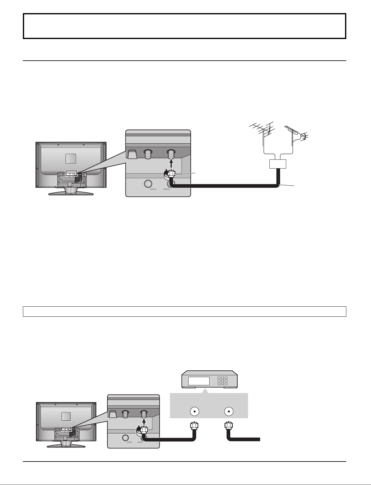
BA
Cable In
ANT
Conexiones
BA
Cable In
ANT
Conexión de la antena
• Para recibir correctamente los canales de VHF/UHF se necesita una antena externa. Para obtener la mejor recepción se
recomienda una antena exterior.
• Para ver programas de TV de transmisión aérea solamente, conecte una antena de casa a ANTENNA (A).
Para ver programas de TV de transmisión aérea y programas de TV por cable, conecte el cable de la TV por cable a
ANTENNA (A), y el cable de antena terrestre a ANTENNA (B).
• Seleccione el modo de antena en Sel. de Entrada (vea la página 15).
Antena de VHF
Adaptador de antena tipo F
(suministrados)
Antena de UHF
Mezclador
Cable coaxial de
75 ohmios
Notas:
• Ciertos sistemas de televisión por cable neutralizan algunos canales para reducir la interferencia o tener canales de alta
calidad (codificados). En estos casos, para que la recepción sea apropiada, será necesario disponer de un decodificador
de televisión por cable. Consulte con su compañía de televisión por cable para conocer los requerimientos de
compatibilidad.
• Para obtener una imagen y un sonido de calidad óptima se necesita una antena, el cable correcto (coaxial de 75 ohmios)
y la clavija de terminación correcta.
• Si se utiliza un sistema de antena comunitaria, tal vez necesite emplear una clavija y un cable de conexión correctos
entre el zócalo de antena de pared y su receptor de televisión.
• El centro de servicio de televisión de su localidad o su concesionario podrán ayudarle a obtener el sistema de antena
correcto para su zona particular y los accesorios necesarios.
• Cualquier tema relacionado con la instalación de la antena, la mejora de los sistemas o accesorios existentes requeridos
y los gastos incurridos son responsabilidad exclusiva de usted, el cliente.
Conexión de decodificador de televisión por cable
• Para ver programas de TV por cable solamente, conecte el cable de TV por cable a ANTENNA (A). Cuando disfrute de
los programas de TV terrestre y de los programas de TV por cable, conecte el cable de TV por cable por cable a
ANTENNA (A) y el cable de la antena terrestre a ANTENNA (B).
• Seleccione el modo de antena en Sel. de Entrada (vea la página 15).
DECODIFICADOR DE
TELEVISIÓN POR CABLE
10
ANT OUT ANT IN
Cable entrante de 75 ohmios
procedente compañía de
televisión por cable
Page 81

Conexiones audio / vídeo
RL
AUDIO
AUDIO OUT
DIGITAL AUDIO OUT
AUDIO IN
L
R
OPTICAL IN
VIDEO
P
R
RL
1
2
1
2
P
B
Y
AUDIO
COMPONENT
VIDEO
VIDEO S-VIDEO
INPUT
AUDIO OUT
INPUT
HDMI
AUDIO IN
DIGITAL AUDIO
OUT
Conexiones
COMPONENT
VIDEO
INPUT
VIDEO
P
P
R
B
Y
1
2
DIGITAL
AUDIO OUT
AV IN
RL
AUDIO
AUDIO OUT
VIDEO S-VIDEO
HDMI
AUDIO IN
INPUT
1
2
Conexión AUDIO OUT
Para una disfrutar de un sonido de teatro en casa completo, un decodificador Dolby Digital∗ externo y un amplificador
multicanal deben ser conectados al conector DIGITAL AUDIO OUT de su TV.
∗El sonido envolvente Dolby Digital de 5.1 canales le permite tener sonido de calidad digital. Dolby Digital provee cinco
canales discretos de ancho de banda completo para frontal izquierdo, frontal derecho, centro, envolvente izquierdo y
envolvente derecho, más un canal de sub-graves LFE (Efecto de Baja Frecuencia).
Ejemplo de conexión del audio de salida
Amplificador
Cable de audio
Cable óptica digital de audio
o
Notas:
• Los altavoces externos no se pueden conectar directamente a los terminales AUDIO OUT.
• Cuando se seleccione un canal ATSC, la salida procedente de la toma DIGITAL AUDIO OUT será Dolby Digital. Cuando
se seleccione un canal NTSC, la salida será PCM.
11
Page 82

Conexiones
Conexión VIDEO 1 / 2 INPUT
COMPONENT
P
R
VIDEO
VIDEO
P
INPUT
B
Y
1
Ejemplo de fuente de la señal de entrada
2
VIDEOGRABADORA
S-VIDEO
OUT
VIDEO
OUT
R
AUDIO
OUT
AUDIO OUT
VIDEO S-VIDEO
HDMI
AUDIO IN
RL
AUDIO
INPUT 1 / 2
AUDIO
L
RL
INPUT
1
2
S-VIDEOVIDEO
Cable de audio
Cable de vídeo
Cable de vídeo S
Nota:
Conecte al terminal S-VÍDEO o VÍDEO.
Conexión COMPONENT VIDEO INPUT
Este televisor es capaz de mostrar imágenes de DTV en formato 1080i y 480p cuando se conecta a un receptor de DTVdecodificador (STB). Este televisor utiliza también un doblador de barrido progresivo, el cual barre la imagen de formato
NTSC de manera progresiva. Esto le permite no ver las delgadas líneas negras (efecto de persianas) que va relacionado
con las imágenes de TV entrelazadas.
• Para ver programas de DTV, conecte el STB a los terminales de entrada de video componente (Y, PB, PR) del televisor.
Las entradas separadas para las señales compuestas de color proveen la separación de luminancia y color.
• Seleccione la salida de 1080i o 480p del STB.
• Debe disponer en su zona de señales de DTV.
• Utilice un DTV-STB (TV digital/decodificador) o un reproductor DVD de Panasonic.
COMPONENT
P
R
VIDEO
VIDEO
P
INPUT
B
Y
1
Ejemplo de fuente de la señal de entrada
Reproductor de DVD
TV digital/decodificador (DTV-STB)
COMPONENT VIDEO OUT
P
B
P
R
AUDIO OUT
Y
L
R
12
Cable de audio
Cable de vídeo componente
AUDIO OUT
VIDEO S-VIDEO
HDMI
AUDIO IN
RL
AUDIO
COMPONENT VIDEO INPUT 1 / 2
AUDIO
RL
P
R
INPUT
1
2
PBY
2
Page 83

AV I N
RL
AUDIO
HDMI AUDIO IN
HDMI IN
HDMI OUT
L
R
VIDEO
P
R
RL
1
2
1
2
P
B
Y
AUDIO
COMPONENT
VIDEO
VIDEO S-VIDEO
INPUT
AUDIO OUT
INPUT
HDMI
AUDIO IN
AUDIO
OUT
1
2
Conexiones
Conexión HDMI
1
∗
HDMI
digital que soporta todos los estándares no comprimidos. El terminal HDMI soporta información de video y audio.
Al terminal de entrada HDMI se puede conectar un dispositivo compatible con EIA/CEA-861/861B
Box o reproductor DVD con terminal de salida HDMI o DVI.
(interfaz multimedia de alta definición) es la primera interfaz A/V para electrónica de consumidor completamente
2
∗
, tal como un Set-Top
• Si el dispositivo externo tiene una salida DVI solamente, utilice un cable adaptador DVI a
HDMI
3
∗
para conectar al terminal HDMI.
• Cuando utilice un cable adaptador DVI a HDMI conecte los cables de audio a los terminales
AUDIO IN.
• Seleccione el ajuste de audio en HDMI In (vea la página 23).
Ejemplo de fuente de la señal
de entrada HDMI
Reproductor de DVD
Caja sobre el Equipo
Cable de audio
Instalación del núcleo de ferrita
Cable HDMI
Núcleo de ferrita (suministrados)
Coloque justo despues del conector.
Tire de las lengüetas
(dos lugares) para abrir.
Ponga el cable y
cierre.
Señal VIDEO compatible
× ×
×
720p
1.080i
480i
× ×
V)
Frecuencia de exploración vertical (Hz)
59,94/60
59,94/60
59,94/60
59,94/60
59,94/60
N° de puntos (H
× ×
×
720p
1080i
480p
480i
1.920
1.280
720
640
720
×
×
× ×
× ×
×
× ×
× ×
× ×
× ×
× ×
× ×
×
× ×
480p
480p
Notas:
• Este terminal de entrada no es para utilización con ordenadores.
• Las señales 720p/1080i serán reformateadas para poderlas ver en la pantalla LCD.
Frecuencia de muestreo compatible de las señales AUDIO a través de HDMI (L.PCM): 48 kHz / 44,1 kHz / 32 kHz
Notas:
• Este conector HDMI es del Tipo A.
• Si conecta un equipo sin terminal de salida digital, conecte al terminal de entrada COMPONENT VIDEO, S VIDEO
o VIDEO del televisor para disfrutar de la señal analógica.
• El terminal HDMI IN sólo puede utilizarse con señales de imagen 720p, 1080i, 480i o 480p. Ajuste la salida del
terminal DIGITAL OUT de la caja digital sobre el aparato a 720p, 1080i, 480i o 480p. Para más detalles, consulte el
manual de instrucciones de la caja digital sobre el aparato. Si no aparecen imágenes porque su caja digital sobre el
aparato no tiene un ajuste de salida de terminal DIGITAL OUT, utilice la entrada de video componente (o la entrada
S Video o la entrada Video). En este caso la imagen aparecerá como una señal analógica.
1. HDMI, el símbolo HDMI y la Interface de Multimedios de Alta Definición son marcas comerciales o marcas
∗
registradas de HDMI Licensing LLC.
2. Los perfiles EIA/CEA-861/861B cumplen con los perfiles para transmisión de video digital sin comprimir/
∗
incluyendo la protección del contenido digital de alto ancho de banda.
3. Cable de conversión HDMI-DVI (TY-SCHO3DH): disponible en el sitio Web de Panasonic
∗
(www.panasonic.com). Consulte a su concesionario de productos electrónicos para conocer más detalles.
13
Page 84

Conexiones
BA
Cable In
ANT
Conexión de CableCARD
CableCARD
TM
le permite sintonizar canales de cable digitales y de alta definición mediante la antena de cable. Consulte
TM
a su concesionario en lo que se refiere a la disponibilidad de CableCARDTM.
Procedimiento
1. Conecte la antena de televisión por cable a ANTENNA (A).
2. Encienda el televisor (vea la página 15).
3. Ponga el modo de entrada en TV (vea la página 8).
4. Inserte la CableCARD
TM
(con el lado superior hacia fuera) en la ranura CableCARD de la parte trasera del
televisor.
Siga los mensajes visualizados en la pantalla.
INSERT THIS END
POD MODULE
Notas:
Cara superior de la tarjeta
• Si nota retrasos en la función del teclado o control remoto cuando utiliza el CableCARDTM, desenchufe el televisor y
vuelva a enchufarlo y pruebe de nuevo con los controles. Si persiste esta condición, llame al Centro de Llamadas del
Cliente de Panasonic para obtener más instrucciones.
• No introduzca la tarjeta PC en la ranura CableCARDTM.
Conexiones del panel frontal
Ejemplo de fuente de la señal de entrada
CÁMARA DE VÍDEO
CONSOLA DE JUEGOS
L
AUDIO
OUT
R
VIDEO
OUT
S-VIDEO
OUT
Los cascos auriculares/
auriculares
(no suministrados)
Cable de vídeo S
Clavija M3
PC CARD
TV/VIDEOOKMENU VOLUME CHANNEL
S VIDEOHPJ VIDEO
ELECT
-
AUDIO-R
L
S VIDEOHPJ VIDEO
INPUT 3
L
-
AUDIO-R
INPUT 3
Cable de vídeo
Cable de audio
Nota:
Conecte al terminal S-VÍDEO o VÍDEO.
14
Page 85

TV VCR DVD
RCVR
LIGHT
SAP
AUX
POWER
DTV
DBS/CBL
TV
POWER
VCR DVD
RCVR
LIGHT
TV/VIDEO
A -ANTENNA - B
SAP
1 2 3
AUX
A
S
P
E
C
T
M
U
T
E
R
E
C
A
L
L
CH
VOL
CH
VOL
OK
MENU EXIT
DTV
DBS/CBL
S
L
E
E
P
POWER
Encendido / apagado de la alimentación
Interruptor de la alimentación
Conectado : Rojo
Conecte el enchufe al tomacorriente.
1
Desconectado: Apagado
PC CARD
ELECT
TV/VIDEOOKMENU VOLUME CHANNEL
L
-
AUDIO-R
S VIDEOHPJ VIDEO
INPUT 3
El botón POWER
2
Sensor del control remoto
Presiónelo para encender o
apagar el televisor.
Nota:
El televisor consumirá algo de energía siempre que
el cable de alimentación esté conectado a una toma
de corriente.
Ajuste Inicial
Para su conveniencia, el menú Ajuste Inicial se mostrará en la pantalla cuando se encienda el televisor por primera vez.
Si lo necesita, siga los menús y los procedimientos mostrados en la pantalla para programar las funciones.
También puede hacer ajustes en el menú Setup (vea las páginas 30-32).
Sel. de Entrada
Seleccione la configuración de la entrada de RF
dependiendo de la fuente de señales.
Presione para seleccionar Sel. de Entrada.
Presione para introducir el campo de submenús.
1
2
VOL
CH
OK
VOL
CH
CH
Presione para seleccionar Cable solamente, Cable/
OK
VOL
3
VOL
VOL
CH
Antena o Antena solamente.
Presione para introducir su elección.
Presione para empezar Auto Escaneo.
CH
OK
VOL
CH
Todos los canales disponibles con una señal se
programarán en la memoria.
Ajuste Inicial
Sel. de Entrada
Auto Escaneo
Lengua
Programacion
Cable/Antena
15
Page 86

Ajuste Inicial
MENU
EXIT
CH
VOL
CH
VOL
OK
Ajuste Inicial
Sel. de Entrada
Español
Auto Escaneo
Programacion
Lengua
Auto Escaneo
Esta función le permite realizar la exploración automática de canales selectivamente.
Puede explorar todos los canales, los analógicos solamente o los analógicos y digitales.
1
2
VOL
VOL
CH
OK
VOL
CH
CH
OK
VOL
Presione para seleccionar Auto Escaneo.
Presione para introducir el campo de submenús.
Presione para seleccionar el submenú.
Presione para empezar Auto Escaneo.
Después de completarse Auto Escaneo, el televisor sintoniza el primer canal encontrado
durante Auto Escaneo.
CH
Lengua
Seleccione el idioma de las visualizaciones en pantalla.
1
Presione para seleccionar Lengua.
Presione para introducir el campo de submenús.
Ajuste Inicial
Sel. de Entrada
Auto Escaneo
Lengua
Escanear Todo
Antena (A) Analoga
Antena (A) Analoga
Antena (B) Analoga
Antena (B) Analoga
& Digital
& Digital
16
2
VOL
CH
OK
VOL
CH
Presione para seleccionar Ingles, Espand o
Frances.
Presione para introducir su elección.
Para volver al menú anterior
Presione para volver.
Para salir de los menús
Presione para volver a la imagen normal.
Notas:
•Si se presiona el botón EXIT en cualquier momento durante Auto Escaneo, Auto Escaneo se cancelará y el televisor
volverá a el menú Ajuste Inicial.
• Si se encuentra presente un CableCARDTM durante Ajuste Inicial y Antena (A) está puesta en Cable, Antena A no
será explorada debido a que el CableCARDTM provee el mapa de canales.
Page 87

Para ver programas de TV
MENU
R-TUNE PROG
EXIT
VCR DVD
RCVR
LIGHT
A -ANTENNA - B
SAP
1 2 3
4 5 6
7 8
0
9
AUX
A
S
P
E
C
T
M
U
T
E
R
E
C
A
L
L
STOP
PAUSE
TV/VCR
REC
CH
VOL
CH
VOL
OK
POWER
TV/VIDEO
TV
FF
SPLIT
PLAY
DTV
DBS/CBL
S
L
E
E
P
TV
OPEN/CLOSE
SPLIT CH
DVD/VCR CH
SWAP
REW
POWER
TV
POWER
VHF y UHF
1
Presione para controlar el televisor con el control
remoto.
2
Presione para encender el televisor.
3
VOL
CH
OK
VOL
CH
Presione para seleccionar el canal deseado.
4
CH
OK
VOL
VOL
CH
Notas:
• El número del canal y el nivel del volumen se fijan incluso después de apagar el
televisor.
• El consumo de energía se pueden reducir si se baja el nivel del volumen.
Presione para seleccionar el nivel del volumen deseado.
Televisión por cable
Asegúrese de haber completado el registro con el proveedor de TV por cable y la
conexión del equipo.
1
CH
OK
VOL
2
VOL
CH
DBS/CBL
3
Notas:
• El número de código del control remoto se establece para los productos
Panasonic.
• Para controlar el producto de otro fabricante, vea las páginas 50-55.
Presione para seleccionar el canal de TV 3 ó 4.
Presione para controlar el sintonizador de cable
con el mando a distancia.
Presione para encender el sintonizador de cable.
Apunte el control remoto hacia el sintonizador de cable.
17
Page 88
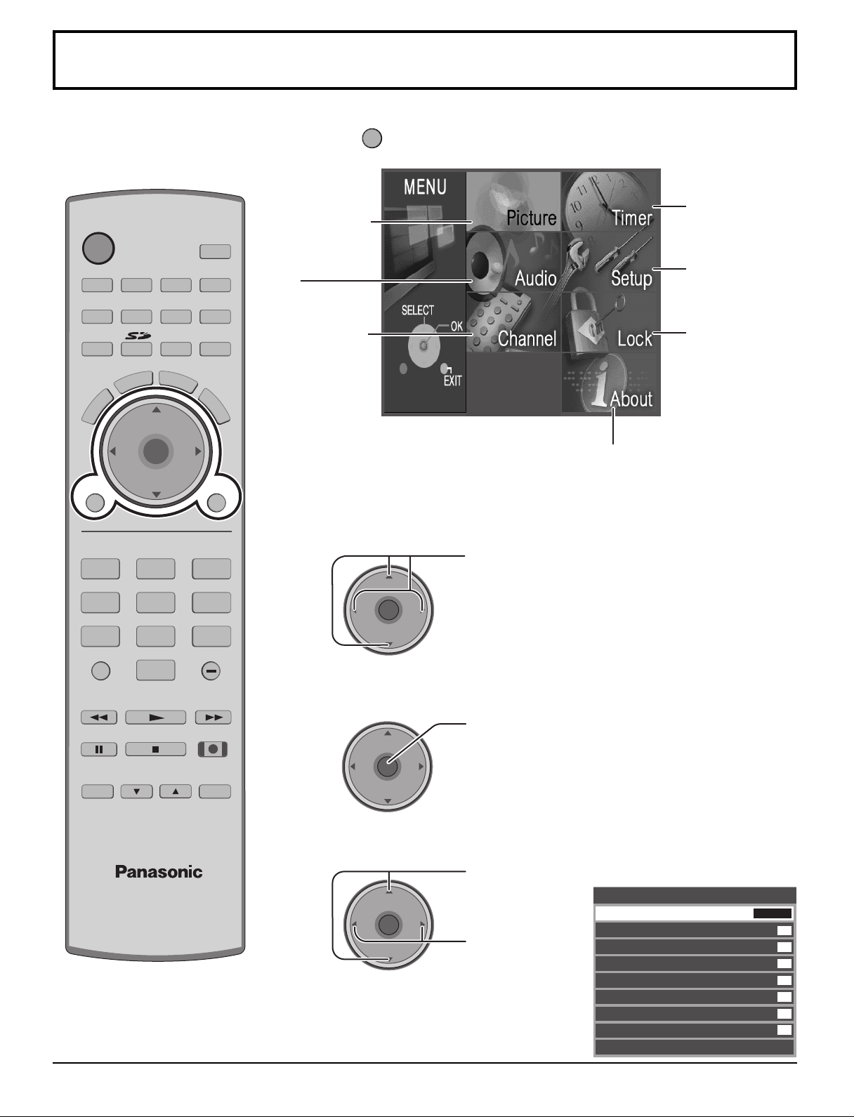
MENU
TV
POWER
R-TUNE PROG
VCR DVD
RCVR
LIGHT
TV/VIDEO
A -ANTENNA - B
SAP
1 2 3
4 5 6
7 8
0
9
AUX
A
S
P
E
C
T
M
U
T
E
R
E
C
A
L
L
STOP
PAUSE
TV/VCR
REC
CH
VOL
CH
VOL
OK
MENU EXIT
FF
SPLIT
PLAY
DTV
DBS/CBL
S
L
E
E
P
TV
OPEN/CLOSE
SPLIT CH
DVD/VCR CH
SWAP
REW
Navegación por menús
CH
VOL
CH
VOL
OK
1
Presione para visualizar el menú principal.
Timer
Picture (Imagen)
(vea la página 20)
Audio
(vea la página 22)
Channel (Canal)
(vea la página 24)
(Temporizador)
(vea la página 27)
Setup
(Programación)
(vea la página 30)
Lock (Bloqueo)
(vea la página 36)
About (Acerca de)
La pantalla About (Acerca de)
muestra información diversa
acerca del televisor. Prepare
esta información cuando llame
2
Presione para seleccionar el menú.
al centro de asistencia al cliente.
18
4
3
VOL
VOL
CH
Presione para introducir el campo de submenú.
OK
VOL
CH
Presione para
CH
VOL
OK
CH
seleccionar el
submenú.
Presione para
ajustar el
submenú.
Ej.: Menú Picture (Imagen)
Imagen
Modo
Luz de Atras
Color
Tinte
Brillo
Contraste
Nitidez
Normal
Otros Ajustes
Vívido
63
31
31
31
63
42
Si
Page 89

Para seleccionar el submenú Otros Ajustes
MENU
EXIT
Navegación por menús
2
1
VOL
VOL
CH
OK
VOL
CH
CH
OK
VOL
CH
Presione para seleccionar Otros Ajustes.
Presione para visualizar el submenú.
Presione para seleccionar el submenú.
Presione para ajustar o activar el submenú.
Para volver al menú anterior
Otros Ajustes
Temp Color
Imagen IA
Realce Color
Reduc de Ruido
3D Y/C Filtro
Matriz Color
MPEG NR
Ajuste Avanzado
Azul
Si
Si
No
Si
SD
No
Presione para volver.
Para salir de los menús
Presione para volver a la imagen normal.
19
Page 90

Navegación por menús
Picture (Imagen)
Imagen
Modo
Luz de Atras
Color
Tinte
Brillo
Contraste
Nitidez
Normal
Otros Ajustes
Modo
Le permite elegir los modos de imagen preestablecidos más apropiados para el programa que usted está viendo. Esta
función también afecta al ajuste Temp Color (vea la página 21).
Vívido
63
31
31
31
63
42
Si
Presione para seleccionar Modo.
Notas:
VOL
CH
OK
VOL
CH
Presione para seleccionar el modo de imagen.
Vívido (predeterminado) : Provee un contraste y una nitidez de imagen realzados para
•
Estandar : Recomendado para ver bajo condiciones normales en una
•
Cinema : Para ver películas en una habitación oscura. Proporciona
•
Usuario : Puede personalizar los ajustes de imagen según sus
•
Auto : Capta automáticamente las condiciones de la luz ambiental
•
ver programas en una habitación bien iluminada.
habitación con iluminación atenuada.
una imagen suave, como la del cine.
preferencias. (vea la página 21, Ajuste Avanzado)
y ajusta el brillo y la gradación en consecuencia para poder
optimizar el contraste.
• Cada modo tiene sus propios ajustes de imagen (Luz de Atras, Color, Tinte, Brillo, Contraste y Nitidez).
• El ajuste personalizado se guarda para TV, Video1, Video2, Video3, Componente1, Componente2, HDMI y el modo de
operaciones de la tarjeta individualmente.
Luz de Atras / Color / Tinte / Brillo / Contraste / Nitidez / Normal
Presione para seleccionar el submenú.
CH
VOL
VOL
OK
CH
Presione para ajustar el submenú.
Elemento Explicaciones
Luz de Atras
Color
Tinte
Brillo
Contraste
Nitidez
Normal
Ajusta la luminancia de la luz de fondo.
Ajusta la intensidad de color deseada.
Ajusta los tonos naturales de la piel.
Ajusta las partes oscuras de la imagen.
Ajusta las partes blancas de la imagen.
Ajusta la calidad de los detalles.
Repone los ajustes de imagen a los ajustes predeterminados en fábrica.
Otros Ajustes
20
VOL
Presione para seleccionar Otros Ajustes.
CH
OK
VOL
CH
Presione para visualizar el submenú.
Otros Ajustes
Temp Color
Imagen IA
Realce Color
Reduc de Ruido
3D Y/C Filtro
Matriz Color
MPEG NR
Ajuste Avanzado
Azul
Si
Si
No
Si
SD
No
Page 91

Navegación por menús
CH
VOL
CH
VOL
OK
Temp Color / Imagen IA / Realce Color / Reduc de Ruido / 3D Y/C Filtro / MPEG NR
Presione para seleccionar el submenú.
CH
VOL
VOL
OK
CH
Presione para ajustar o activar el submenú.
Elemento Explicaciones
Temp Color
Imagen IA
Realce Color
Reduc de Ruido
3D Y/C Filtro
MPEG NR
Para aumentar o disminuir los colores Warm (rojo) y Cool (azul) según las
preferencias personales.
Visualiza el blanco y negro más vívidamente cuando está encendido.
Para aumentar la gama de reproducción de colores con gradación de colores
natural y tonos sumamente delicados.
Reduce el ruido, comúnmente conocido como nieve. Déjelo apagado cuando
reciba una señal fuerte.
Minimiza el ruido y la diafotía cromática de la imagen.
Se reducirá el ruido exclusivo de DVD, STB, etc.
Matriz Color
Visualiza señales de entrada 480p en color natural de fuentes de vídeo digital conectadas a los terminales
COMPONENT VIDEO INPUT (Y, PB, PR).
Seleccione HD o SD para ajustar automáticamente los parámetros del color para HD (alta definición) y SD (definición
estándar).
Presione para seleccionar Matriz Color.
Presione para seleccionar SD o HD.
SD : Cuando la señal de entrada es de un sistema de TV normal (NTSC).
•
HD : Cuando la señal de entrada es de un sistema de alta definición (ATSC).
•
Notas:
• Esta función sólo se encuentra disponible con imágenes 480p, y no se encuentra disponible con programas de
televisores (NTSC) convencionales.
• Cuando vea un formato de señal DTV que no sea estándar, usted podrá cambiar manualmente los parámetros del
color para obtener la mejor calidad de la imagen.
Ajuste Avanzado
Esta función solamente estará disponible cuando usted seleccione Usuario en Modo.
1
CH
OK
VOL
VOL
CH
2
CH
OK
VOL
Trans. B & N
Resolución
Aj. de Gamma
Exp. de Negro
Aj. de Caracter
Normal
VOL
CH
Elemento
Presione para seleccionar Ajuste Avanzado.
Presione para visualizar el submenú.
Presione para seleccionar Ajuste Avanzado.
Presione para seleccionar Si.
Si : Disponible para seleccionar y ajustar el submenú.
•
No : No está disponible para seleccionar y ajustar el submenú.
•
Explicaciones
Mejora los bordes en el fondo para reducir la sobretoma y mejorar la
sensación de profundidad.
Enfatiza la nitidez en densidad de muchos colores diferentes.
Aumenta el brillo de los rangos centrales para mejorar los detalles y el
contraste en escenas oscuras.
Mejorará el nivel de contraste.
Hace más brillantes a los caracteres blancos.
Repone todos los ajustes avanzados a sus valores de fábrica.
Ajuste Avanzado
Ajuste Avanzado
Trans. B & N
Resolución
Aj. de Gamma
Exp. de Negro
Aj. de Caracter
Normal
Si
Medio
Medio
Medio
8
8
Si
21
Page 92

Navegación por menús
Audio
Audio
Bajos
Altos
Balance
Normal
Otros Ajustes
Bajos / Altos / Balance / Normal
7
7
31
Si
Presione para seleccionar el submenú.
CH
OK
VOL
CH
Otros Ajustes
CH
OK
VOL
CH
VOL
VOL
Presione para ajustar o activar el submenú.
Elemento
Bajos
Altos
Balance
Normal
Aumenta o disminuye la respuesta de los graves.
Aumenta o disminuye la respuesta de los agudos.
Realza el volumen de los altavoces izquierdo / derecho.
Repone los ajustes de Bajos, Altos y Balance los ajustes
predeterminados en la fábrica.
Explicaciones
Presione para seleccionar Otros Ajustes.
Presione para visualizar el submenú.
Otros Ajustes
Sonido IA
Envolvente
Altavoces
Ent. HDMI
Si
No
Si
Auto
Sonido IA
Iguala los niveles de volumen generales en todos los canales.
Presione para seleccionar Sonido IA.
VOL
CH
OK
VOL
CH
Presione para seleccionar Si u No.
22
Page 93

Envolvente
Mejora la respuesta de audio cuando se escucha sonido estéreo.
Presione para seleccionar Envolvente.
Navegación por menús
VOL
CH
OK
VOL
CH
Presione para seleccionar Si u No.
Si : Surround encendido
•
No : Surround apagado
•
Altavoces
Esta función hace que la voz suene clara.
Presione para seleccionar Altavoces.
VOL
CH
OK
VOL
CH
Presione para seleccionar Si u No.
Si : El ecualizador funciona normalmente.
•
No : Ecualizador apagado.
•
Ent. HDMI
Cuando se utiliza HDMI (vea la página 13), esta función le permitirá cambiar entre entrada analógica y entrada digital.
Presione para seleccionar Ent. HDMI.
VOL
CH
OK
VOL
CH
Presione para seleccionar el modo.
Auto : Selecciona automáticamente la señal analógica / digital.
•
Digital : Entrada digital solamente.
•
Analogo : Entrada analógica solamente.
•
23
Page 94

CH
VOL
CH
VOL
OK
Navegación por menús
Favoritos
Modo de navegacion
Todos los Canales
Entrada de RF
Antena (A)
Canal
A: 2
16 canales favoritos maximo.
Channel (Canal)
Favoritos
Le permite crear una lista de canales favoritos desde Antena (A) o Antena (B).
Presione para seleccionar Favorite.
CH
OK
VOL
VOL
CH
Modo de navegacion
Entrada de RF
CH
OK
VOL
VOL
CH
Presione para visualizar el submenú.
Presione para seleccionar Modo de navegacion.
Presione para seleccionar Favoritos o Todos los
Canales.
Presione para introducir su elección.
Presione para seleccionar RF Input.
Presione para seleccionar Antena (A) o Antena (B).
Presione para introducir su elección.
Canal
24
VOL
Presione para seleccionar Canal.
CH
OK
VOL
CH
Presione para seleccionar el canal.
Presione para agregar un canal.
Para borrar un canal, presione de nuevo mientras se muestra el número del canal.
Repita el paso 2 para programar un máximo de 16 canales favoritos.
Page 95

Navegación por menús
1 2 3
4 5 6
7 809
CH
VOL
CH
VOL
OK
Titulado
Para introducir etiquetas manuales y prefijadas en las emisoras deseadas. También para introducir etiquetas de entrada
en las entradas de video.
Presione para seleccionar Titulado.
VOL
CH
OK
VOL
CH
Presione para visualizar el submenú.
Prefijado
Para introducir números de canales para emisoras de TV populares.
1
2
VOL
CH
OK
VOL
CH
Presione para seleccionar Prefijado.
Presione para introducir el campo de submenús.
Presione para seleccionar Entrada de RF.
Presione para seleccionar Antena (A) o Antena (B) .
Presione para introducir su elección.
Titulado
Prefijado
Titulos Manuales
Ponga Titulo
Entrada de RF
ABC
CBS
FOX
NBC
PBS
CNN
ESPN
HBO
Antena (A)
3
4
5
VOL
VOL
CH
OK
VOL
CH
CH
OK
VOL
CH
Presione para seleccionar los subtítulos prefijados deseados.
Seleccione el canal (consulte su guía de TV local).
Presione para introducir su elección.
Para eliminar un número de canal, mientras se encuentra resaltado, presione
repetidamente hasta eliminar todos los números, y luego presione OK.
Nota:
Sólo se pueden seleccionar entradas con señales.
25
Page 96

Navegación por menús
Titulos Manuales
Para introducir números y subtítulos manualmente.
1
VOL
CH
OK
VOL
CH
Presione para seleccionar Titulos Manuales.
Presione para introducir el campo de submenús.
Titulado
Prefijado
Titulos Manuales
Ponga Titulo
Entrada de RF
Canal
Titulos
Antena (A)
A: 2
3
4
2
VOL
VOL
VOL
Presione para seleccionar Entrada de RF.
CH
OK
VOL
Presione para seleccionar Antena (A) o Antena (B) .
Presione para introducir su elección.
CH
Presione para seleccionar Canal.
CH
OK
VOL
CH
Presione para seleccionar el número de canal disponible.
Presione para seleccionar Titulps.
CH
OK
VOL
CH
5
VOL
CH
OK
VOL
Presione para seleccionar la posición del carácter.
Presione para seleccionar el carácter (consulte su guía de TV local).
CH
Repita hasta añadir todos los caracteres. Se puede añadir un máximo de 7 caracteres
por cada canal.
Para borrar el carácter seleccionado, pulse hasta que no se muestren caracteres.
Presione para introducir su elección.
Nota:
Sólo se pueden seleccionar entradas con señales.
26
Page 97

Navegación por menús
Ponga Titulo
Para etiquetar las conexiones de entrada de video para la visualización en pantalla.
1
VOL
CH
OK
VOL
CH
Presione para seleccionar Ponga Titulo.
Presione para introducir el campo de submenús.
Titulado
Prefijado
Titulos Manuales
Ponga Titulo
Componente 1
Componente 2
HDMI
Video 1
Video 2
Video 3
2
CH
OK
VOL
VOL
CH
Cronometro
Cronometro
Apagado
Cronometro
Reloj
Aj. de Dia
Presione para seleccionar la entrada de video.
Presione para seleccionar la etiqueta de video prefijada.
Para eliminar las etiquetas de entrada, presione hasta que no se muestren etiquetas, y
luego presione el botón OK para introducción su elección.
Para saltar la entrada, seleccione “BRINCAR”. La entrada se omitirá cuando presione
TV/VIDEO.
Presione para introducir su elección.
No
- -
- - : - -
- - -
Apagado
VOL
Presione para seleccionar Apagado.
CH
OK
VOL
Presione para seleccionar la hora para dormir (No, 30, 60 o 90).
Para apagar el temporizador, seleccione No.
Para confirmar el tiempo restante, presione el botón RECALL (vea la página 8).
CH
27
Page 98

Navegación por menús
Cronometro
Ponga la hora el Reloj (vea la página 29) antes de poner el Cronometro.
Ponga el Cronometro para encender y apagar el televisor a las horas seleccionadas y en el día seleccionado.
CH
OK
VOL
VOL
CH
Dia
CH
OK
VOL
VOL
CH
Encender / Apagar
1
CH
OK
VOL
VOL
CH
Presione para seleccionar Cronometro.
Presione para visualizar el submenú.
Presione para seleccionar Dia.
Presione para seleccionar el ajuste del día apropiado.
Presione para seleccionar Encender o Apagar.
Presione para introducir el campo de la hora.
Cronometro
Apagado
Cronometro
Reloj
Aj. de Dia
Cronometro
Dia
Encender
Apagar
Fijar
No
AM12 : 01
LUN
LUN-VIE
7 : 10 AM
8 : 10 PM
Activar
2
3
VOL
VOL
CH
OK
VOL
CH
CH
OK
VOL
CH
Presione para seleccionar la posición de las horas (AM o PM) o los minutos.
Presione para poner la hora (AM o PM) y los minutos.
Presione para introducir su elección.
Notas:
• El televisor se apaga automáticamente después de pasar 90 minutos cuando se enciende mediante el Cronometro.
Esto se cancelará si se selecciona Apagar o se presiona una tecla.
• Cuando el suministro eléctrico del televisor se altere debido a un corte en el suministro o a un problema similar, el
temporizador de apagado se desactivará y el televisor se pondrá en el modo de espera incluso después de
restablecerse el suministro eléctrico.
Fijar
Presione para seleccionar Fijar.
VOL
CH
OK
VOL
Presione para seleccionar Activar o No.
28
CH
Page 99

Para activar el temporizador
Seleccione el canal y apague el televisor.
Reloj
Navegación por menús
1
2
3
VOL
VOL
VOL
Presione para seleccionar Reloj.
CH
OK
VOL
CH
Presione para introducir el campo de la hora.
Presione para seleccionar la posición de las horas (AM o PM) o los minutos.
CH
OK
VOL
CH
CH
OK
VOL
CH
Presione para poner la hora (AM o PM) y los minutos.
Presione para introducir su elección.
Aj. de Dia
Ponga el día de la semana.
CH
OK
VOL
VOL
CH
Presione para seleccionar Aj. de Dia.
Presione para seleccionar el día de la semana.
29
Page 100

Cable/Antena
Programar Canal
Sel. de Entrada
Programacion
Auto Escaneo
Prog. Manual
Medidor de señal
Lengua
CH
VOL
CH
VOL
OK
Navegación por menús
Setup (Programación)
Programar Canal
Presione para seleccionar Programar Canal.
VOL
CH
OK
VOL
CH
Presione para visualizar el submenú.
Sel. de Entrada
Le permite especificar el modo de antena (Cable Solamente, Cable/Antena o Antena Solamente).
1
Presione para seleccionar Sel. de Entrada.
Presione para introducir el campo de submenús.
2
VOL
CH
OK
VOL
CH
Presione para seleccionar el modo de antena.
Presione para introducir su elección.
Aparece el mensaje de confirmación.
30
3
VOL
CH
OK
VOL
CH
Presione para empezar Auto Escaneo.
Todos los canales disponibles con una señal se programarán en la memoria.
Notas:
• Auto Escaneo es necesario para cuando usted selecciona la señal de entrada por primera vez o siempre que usted
cambia la configuración de la antena.
• Si no está insertado el CableCARDTM, Exploración automática realizará Escanear Tado.
• Cuando esté insertado el CableCARDTM y se seleccione Cable Solamente, Auto Escaneo se omitirá.
• Cuando esté insertado el CableCARDTM y se seleccione Cable/Antena, Auto Escaneo realizará Antena (B) Analoga
& Digital.
• Para poder seleccionar manualmente Antena B desde el control remoto, tendrá que realizar en primer lugar Exploración
automática.
 Loading...