

Page 1

Colour Television
TC-29V1Z
Operating Instructions
Please read these instructions completely before operating this set
and retain it for future reference.
TQB620745
Page 2

\
Page 3

Dear Panasonic Customer
Welcome to the Panasonic family of Customers.
We hope that you will have many years of enjoyment from your new
colour television set.
Page 4

Contents
Before operating this set
Battery instaliation and Repiacement
..........................................
.......................
6
7
How to open the door on the rear of Remote Control ... 8
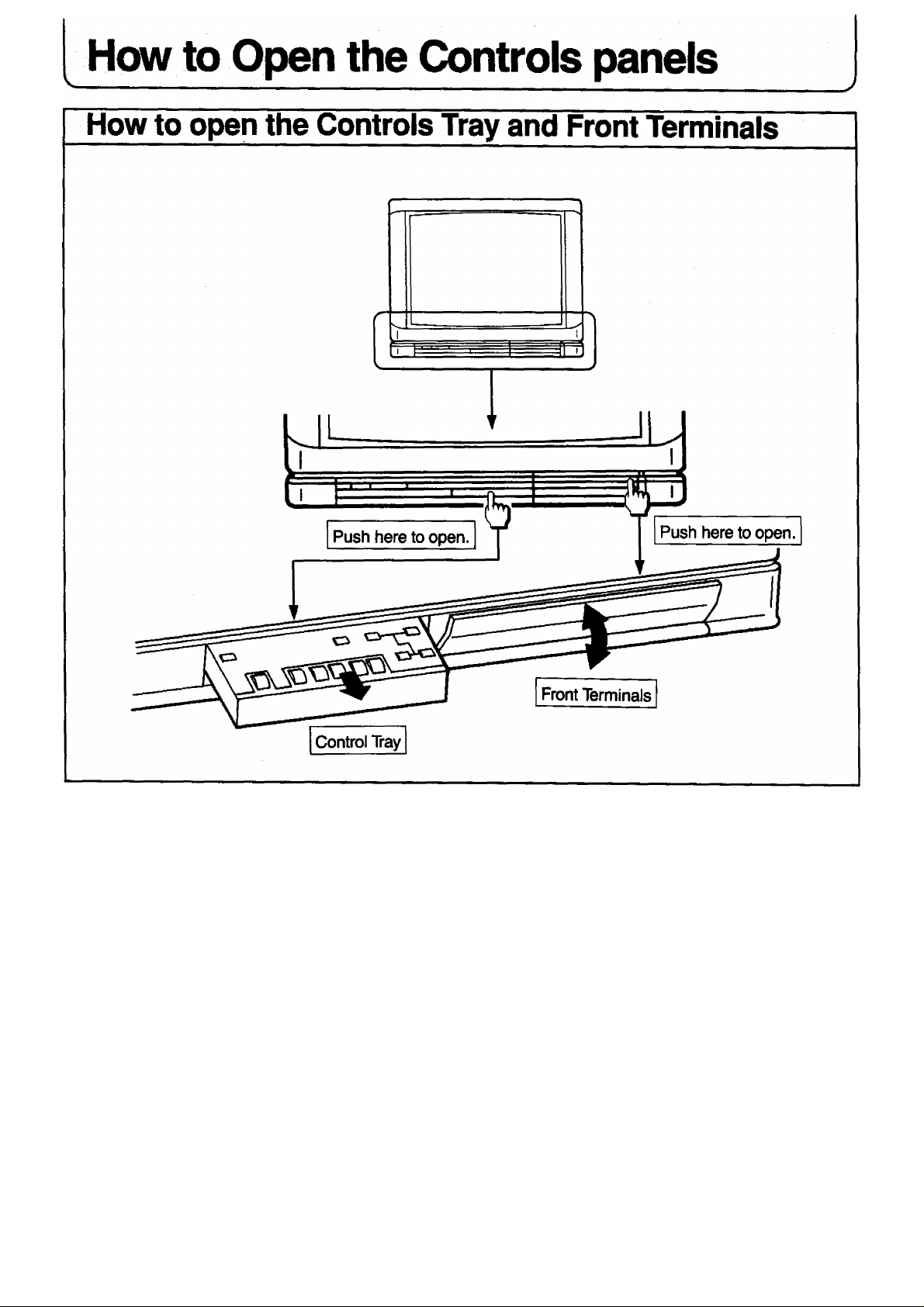
How to Open the Controls panels
Location of Controls for TV set
.............................
.................................
9
10
Location of Controls for Remote Control
Front Side on the Remote Control
Behind the Door on the Remote Control
Location of Terminals
.............................................
How to Connect an Aerial
Automatic Turn off Function
.........................................................
................................................
........................................
....................................
12
14
16
18
19
Connection
Pattern 1 : Via the “AVI ” S-Video and Audio Terminals
2 : Via the “AV2” S-VIdeo and Audio Terminais
3 : Via the “AV3” S-Video and Audio Terminais
..........................
..........................
..........................
20
22
24
4 : Via the “AVI” Video and Audio Terminais
5 : Via the “AV2” Video and Audio Terminals.
6 : Via the “AV3” Video and Audio Terminals
7 ; Via the “Monitor Out” Terminals
Connecting the Headphones
Connecting the External Speakers
Connecting the Surround Speakers
.................................................
.........................................................
.......................................................
.................
Tuning Procedure (Automatic Search)
..............................
...........................
.............................
..........................
................
......................
26
28
30
32
33
34
35
36
Tuning Procedure (Manual Search)...........................38
Fine Tuning Operation..............................................40
Tuning the TV set to the VCR
Programme Name Writing Operation
....................................
.......................
42
44
Programme Number Skip Operation.........................46
Page 5

Contents
Basic Operation on the TV Set
.................................
48
General Operation on the TV Set...............................50
Basic Operation on the Remote Controller
NiCAM Digital Stereo Reception
...............................
................
54
56
Picture Menu Operation
Menu Select Operation
To Adjust the Picture Menu
...........................................................................
.................................
..................................59
58
Sound Menu Operation
Menu Select Operation.............................................................................60
To Adjust the Sound Menu
Surround Operation
To Adjust the Surround Level
General Operation on the Remote Controller
......................................................................
......... .......................................
..............................................................64
............
61
62
66
Operation for VCR
Warnings and Cautions
...................................................
............................................
70
72
Troubleshooting.......................................................73
Specifications...........................................................74
Page 6
Before operating this set
Preparations
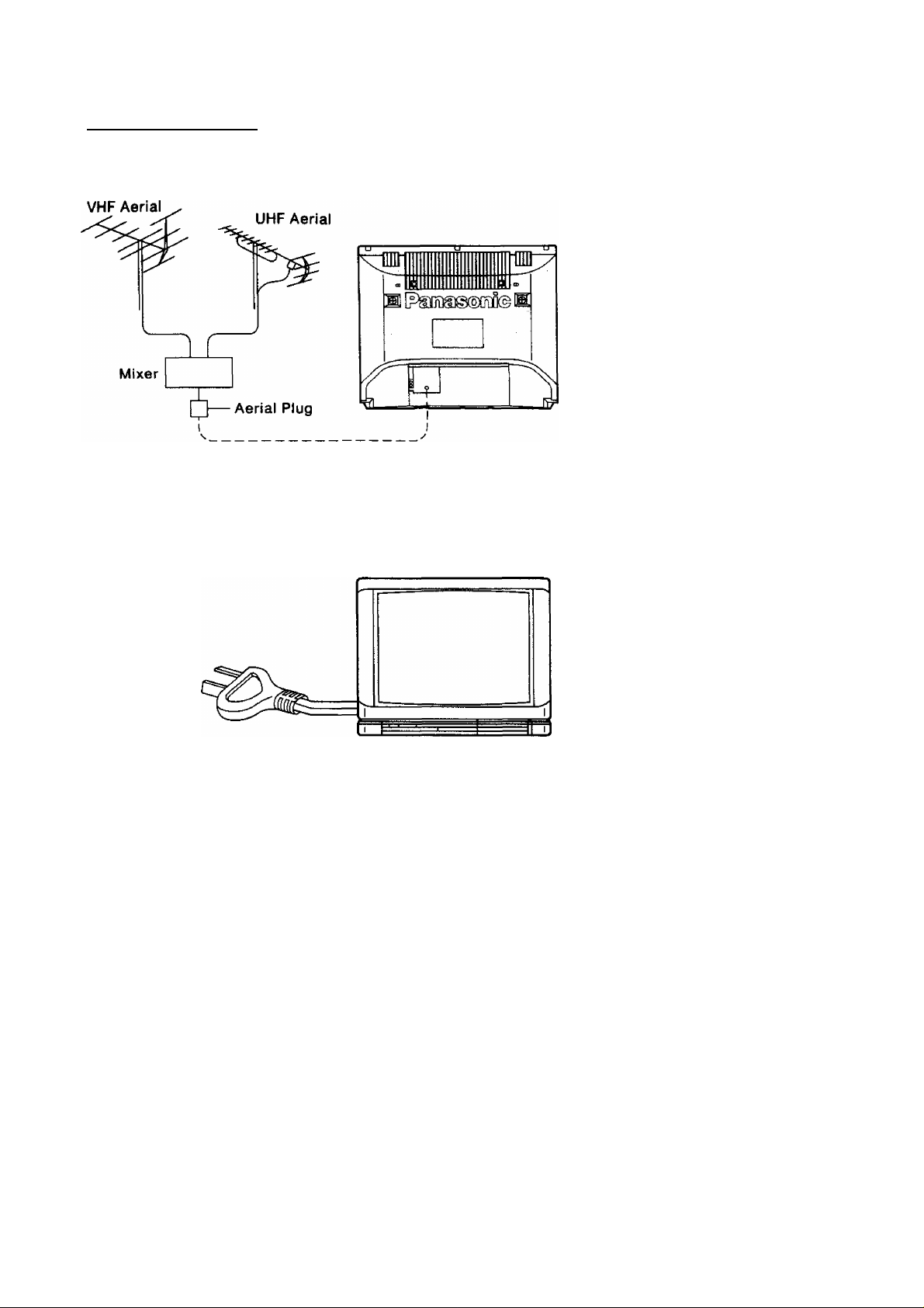
Connect the Aerial Cable to the RF In Terminal
How to connect an Aeriai
For connection details refer to page 18i
Connect the Plug to the wall outlet
\
Ú
For Warnings and Cautions details, refer to page 72.
Connect the AC Plug to AC Outlet
Note:
Remove the plug from the wall outlet
when the TV set is not used for a
prolonged period of time.
N
Page 7
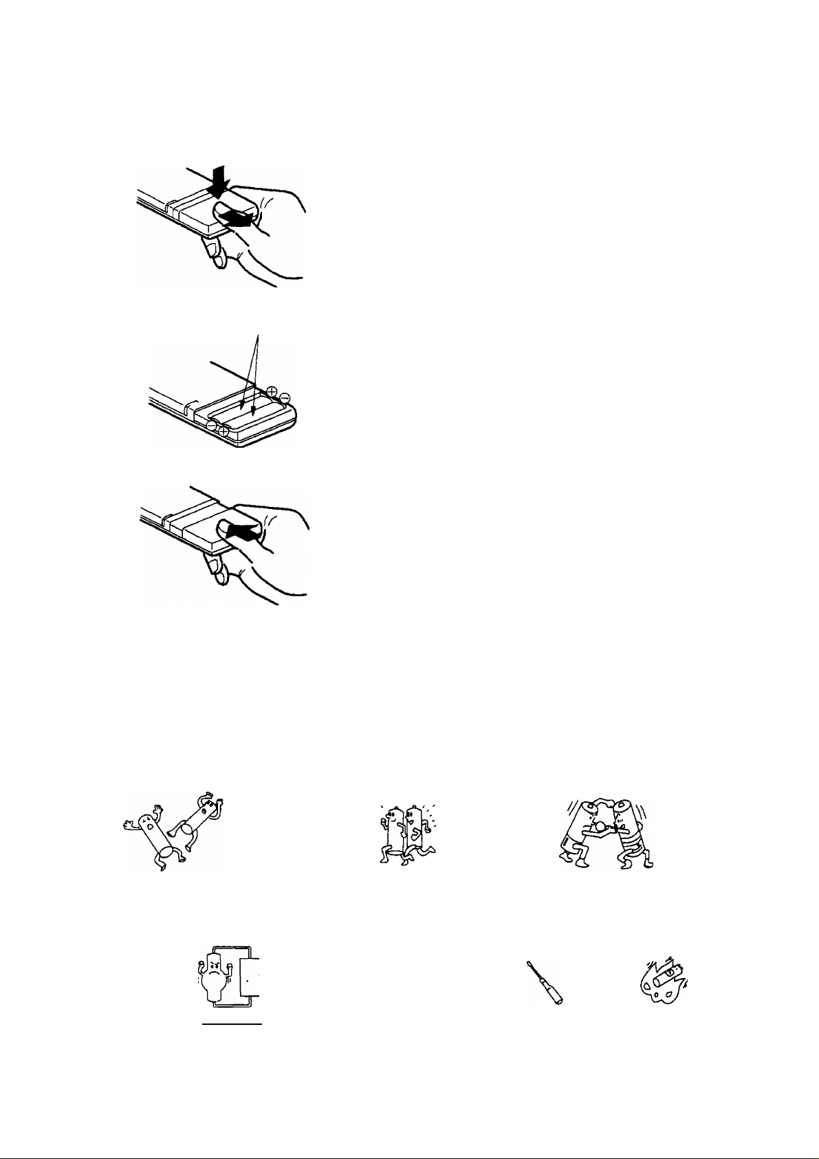
Battery Installation and Replacement
Batteries: Use two “R6” size aiicaiine batteries
1
Open the cover.
Push down stopper and remove the cover.
Two “R6” size
Replace the batteries.
Insert the batteries with the correct polarity as
indicated by the “ + ’ ’ and “ - ” symbols.
Replace the cover.
Do not use rechargeable (Ni-Cd) batteries.
They are partially different in shape and performance and may fail to ensure the desired function.
Battery precautions
The incorrect use of batteries can cause electrolyte leakage which will corrode the remote control transmitter
or cause the batteries to burst. The following precautions must be observed carefully.
Old Batteries New Batteries
Replace both batteries at the same time.
Dispose of them immediately.
Don’t
X X
V 1 I ( /
Don’t mix battery types
(alkaline with carbon zinc, etc.)
X
Fire
X
Recharge
Short-circuit
CO
Disassemble
Heat or Burn
Page 8
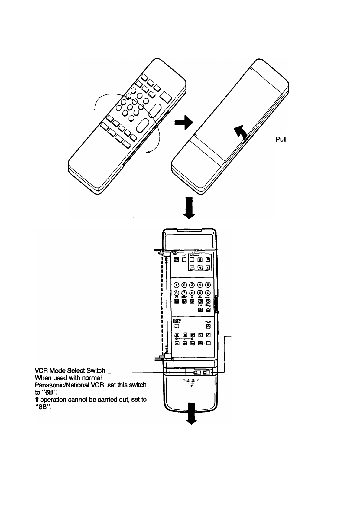
How to open the door on the rear of Remote Control
(Front) ( Rear)
here to
open.
8
S-Position:
With the door open, the buttons on
the front cannot be used.
(Only the buttons under the door
can be used.)
D-Position:
The buttons on the front and
under the door can be used.
Place the Remote Control in such
a way that all Buttons on both
sides can be used easily.
Open the cover
(Push down and Slide the cover out.)
\
Page 9
Page 10
Location of Controls for set
______
-__________
___
________________^^—__________________________________
inside the Tray
__________________
_____
___________-________
■■ ..
..................................
-■ - J
10
Page 11

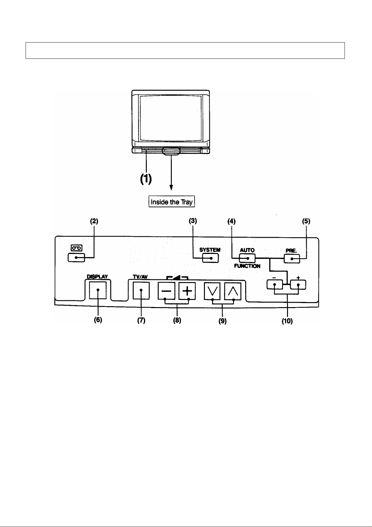
Location of Controls for TV set
No. Description
J1)l_
(2)
(3)
(4)
(5)
(6)
(7)
(8)
(9)
Power Switch
Game Position Button
System Selection Button
Auto/Function Button
Preset Button
Display Button
TV/AV Selection Button
Volume Up and Down Buttons
Programme Number Up and Down Buttons
(10) Level Adjust Buttons
11
Page 12
Location of Controls for Remote Control
___________________________________________________
Front Side on the Remote Control
_______
__________________________ -_____________________________
^__________________________________________________________
When the TELETEXT kit:
Model TY-TA2 (Optional) is
adapted, use these buttons.
For TELETEXT operation
refer to the Operating
Instructions supplied with
the TELETEXT Kit.
12
Page 13

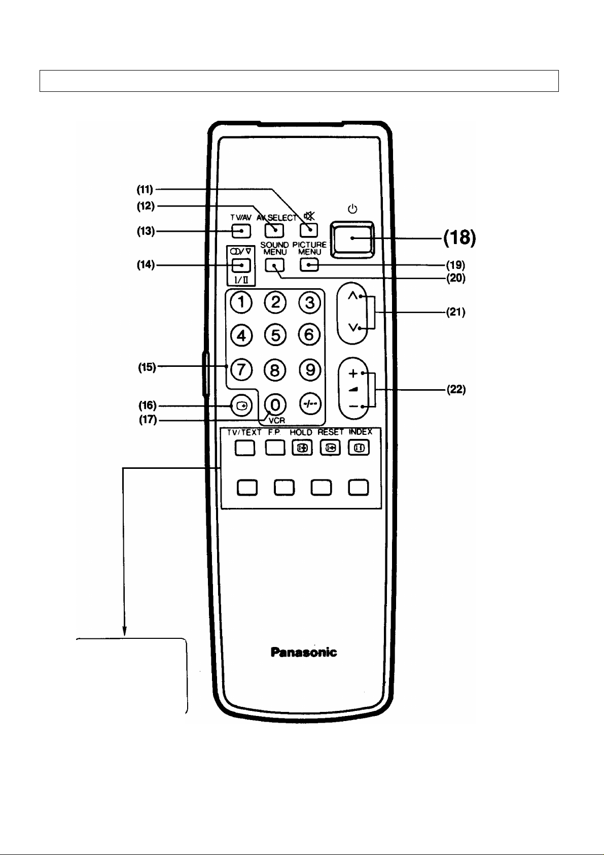
Location of Controls for Remote Control
No. Description
(11)
(12) AV Selection Button
(13)
(14)
(15)
(16) Recall Button
(17)
Mute Button
TV/AV Selection Button
NICAM Sound Selection Button
Direct Programme Number Selection Buttons
0/VCR Button
(18) Power (Stand-by) Button
(19)
(20)
(21)
(22)
Picture Menu Button
Sound Menu Button
Programme Number Up and Down Buttons
Vblume Up and Down Buttons
13
Page 14
Location of Controls for Remote Control
Behind the Door on the Remote Control
14
Page 15

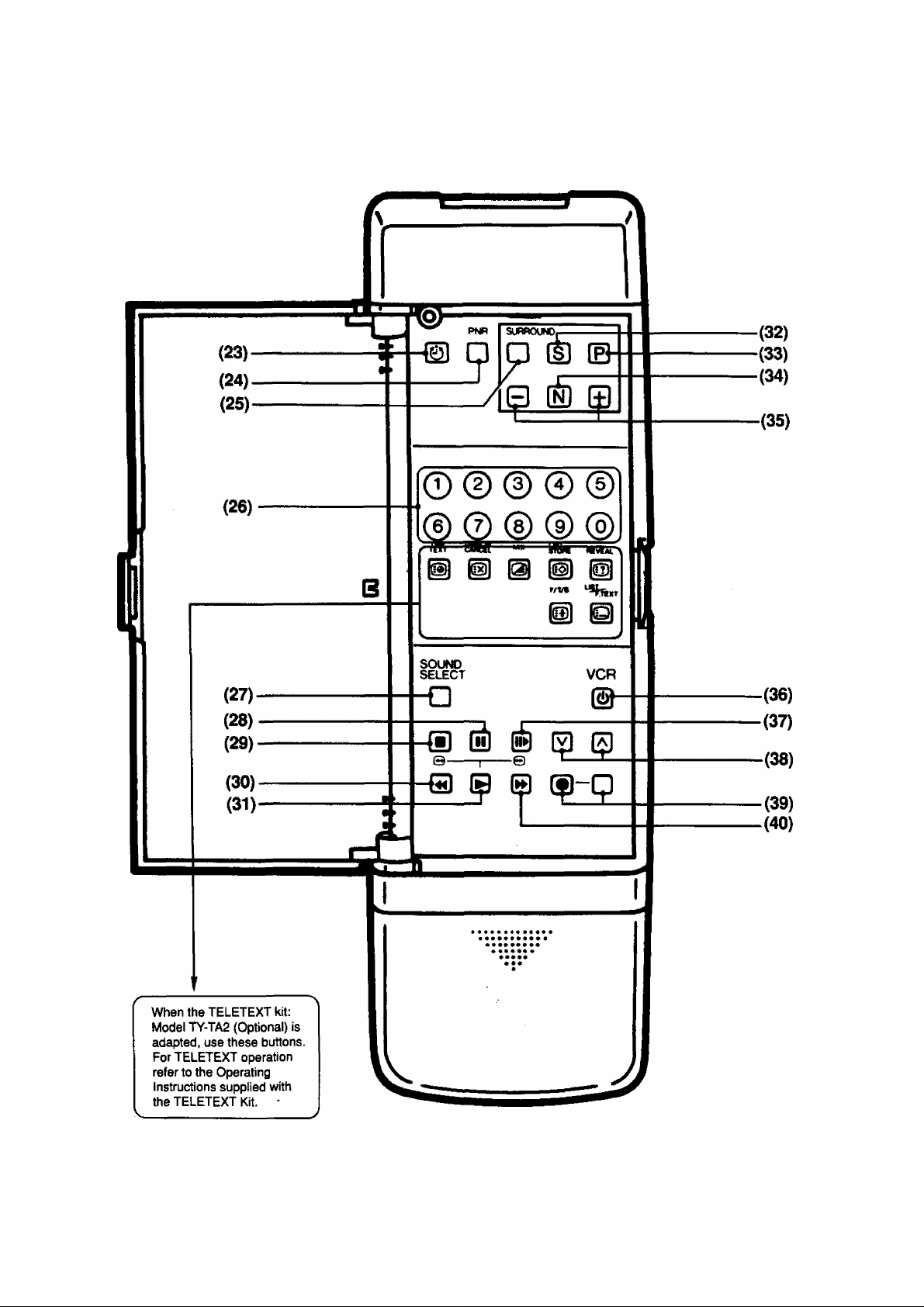
Location of Controls for Remote Control
No.
(23)
(24)
(25)
(26)
(27)
(28)
(29)
(30)
(31)
(32)
(33)
(34) Normalisation Button
Description
Off-Timer Button
Picture Noise Reduction Button
Surround Button
Numerical Buttons
Sound Selection Button for VCR
Pause Stiii Button
Stop Button
Rewind/Review Button
Play Button
Sound Function Button
Picture Function Button
(35)
(36)
(37)
(38)
(39)
(40)
Function level Up and Down Buttons
VCR Power Button
Stilt Advance Button
Programme Number Up and Down Buttons for VCR
Record Buttons
Fast Forward Button
15
Page 16
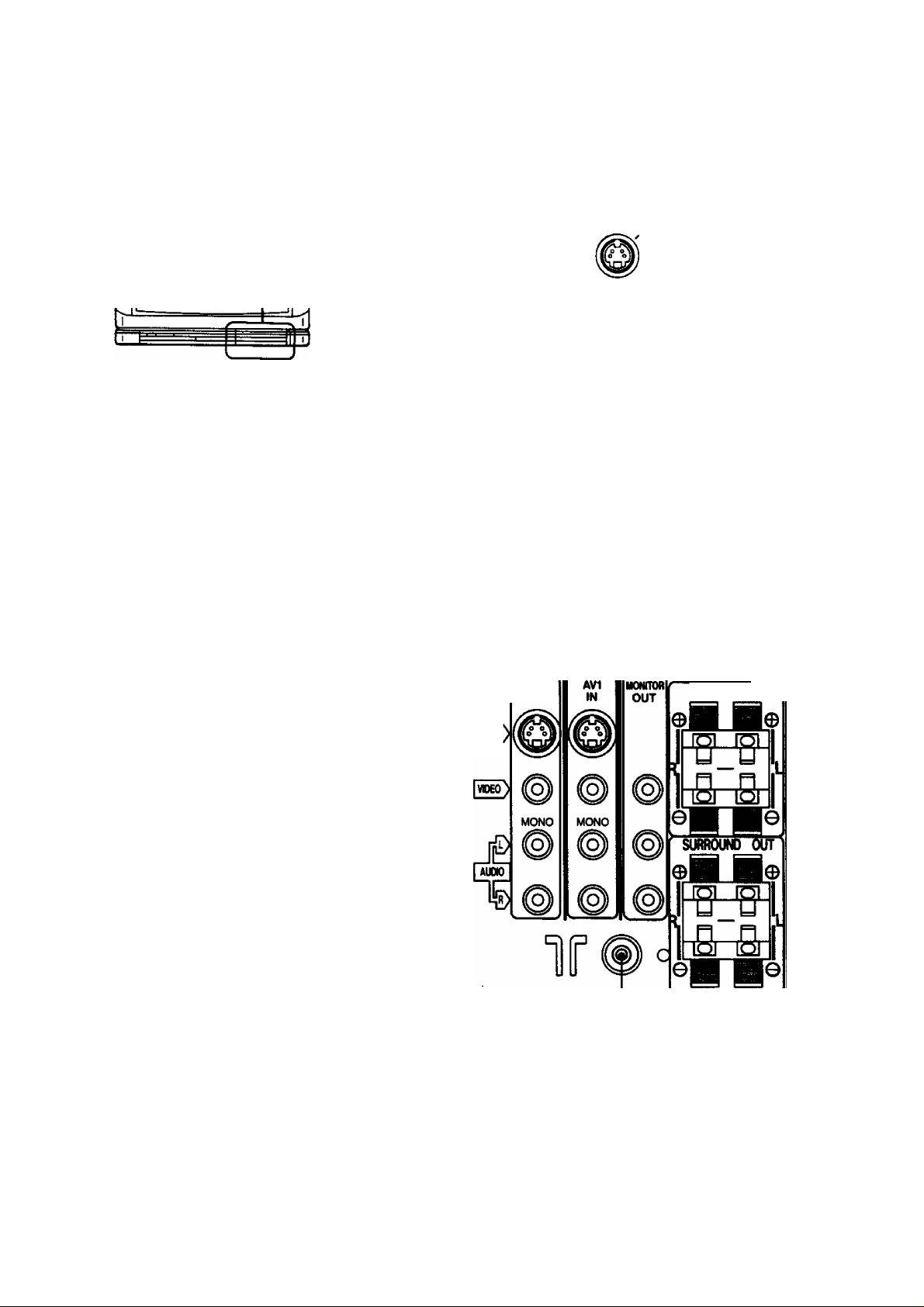
Location of Terminals
Location of Front and Rear Terminals
AV2 IN
L
s>®
S-VIOEO
(41)
57
(43) (44) (45)
AV3
IN
VIDEO
(42)
L/MONO
AUDIO
(46) (47)
Lwr-ilTlEx
EXTSP.(80)
16
S-VDEO
(48) (49)
Page 17

Location of Terminals
No. Description
(41)
(42)
(43) AV 3 Input Terminals
(44) AV 1 Input Terminals
(45)
(46)
(47)
(48) Aerial Terminal
(49)
Headphones Jack
AV 2 Input Terminals
Monitor Out Terminals
Speaker Selection Switch
External Speaker Terminals
Surround Speaker Terminals
\
17
Page 18
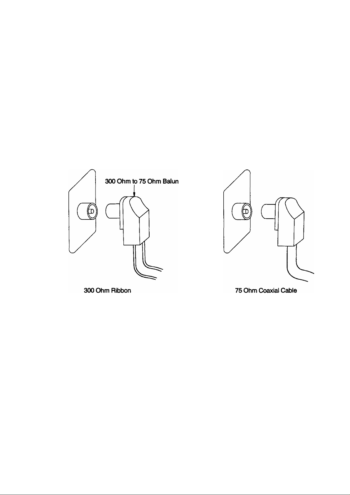
How to Connect an Aerial
To obtain the best quality picture and sound, an Aerial, the correct cable (75 Ohm coaxial) and the correct
terminating plug will be required.
If a communal Aerial system is used, you may require the correct connection cable and plug between the
wall Aerial socket and your television receiver.
Your local Television Service Agent or Dealer may be able to assist you in obtaining the correct Aerial
system for your particular area and any accessories required.
Any matters regarding Aerial installation, upgrading of existing systems or accessories required, and the
costs incurred, are the responsibility of the customer.
Note:
If your existing Aerial system uses 300 Ohm ribbon cable you will require to use a 300 Ohm to 75 Ohm
Baiun.
See below.
or
18
Page 19

Automatic Turn-off Function
V ■ ■ • • ■ ■ ^ ^ • ■ . - ...... • •
Noise Timer
If the set is not switched off when the TV station stops transmitting.
It will automatically go to stand-by condition after 30 munutes.
Note:
This function will not operate when the Television receiver is on AV mode.
J
19
Page 20
Connection
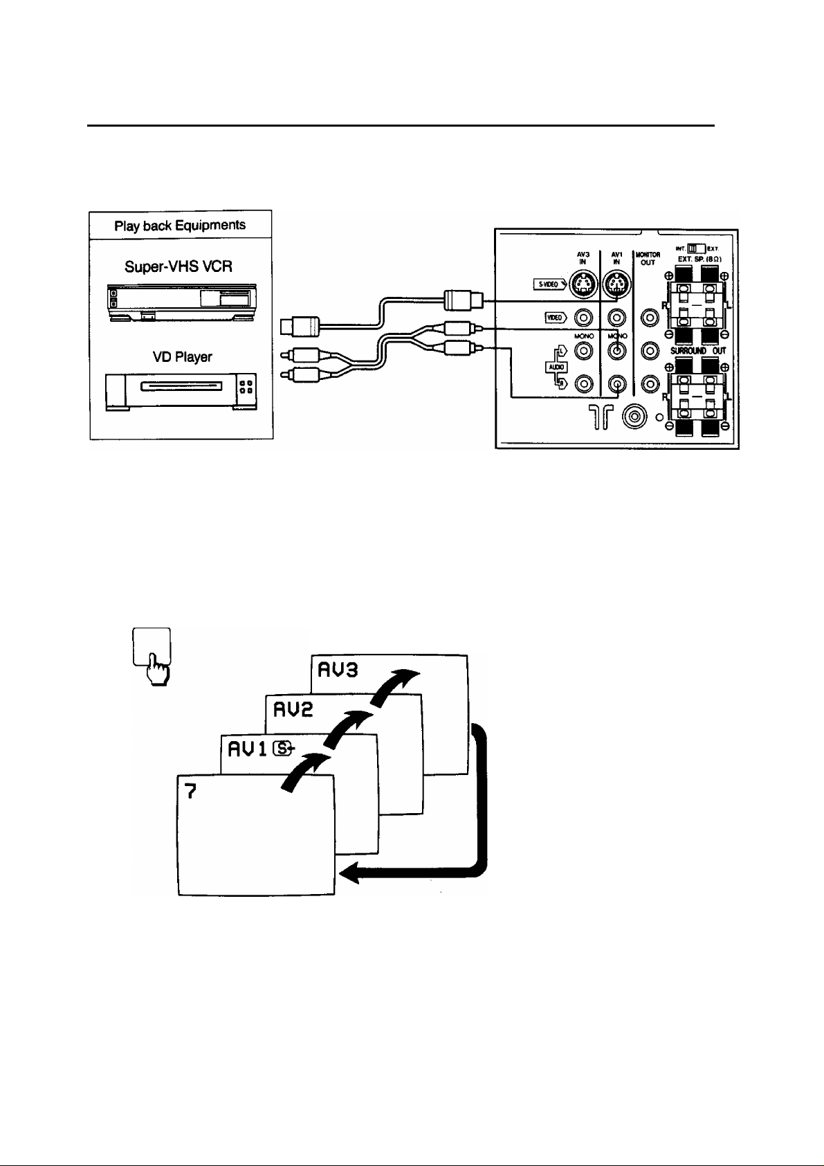
Pattern 1: Via the “AVI” S-Video and Audio Terminals
Connect the “AV1" (S-Video and Audio) Terminals and Other Equipments as follows.
AV1 Select Operation on the TV set
1.
2.
TV/AV
PLAY
Select the “AV1” mode by pushing this button, you can sequentiaily
select TV and three AV modes (AV1, AV2 and AV3), as shown below.
Selecting mode will appear on the top left of the screen.
Push the “PLAY" Button on the Connected Equipment.
Note:
When the S-Video cable is connected to
AV1 (S-Video) Terminal, the “S-Video”
symbol will be displayed on the screen as
shown left.
20
Page 21
Connection
AV1 Select Operation on the Remote Controller
1.
2.
TV/AV
AV SELECT
Push the “TV/AV” Button on the Remote Controller.
Then last selected AV mode will be displayed on the screen.
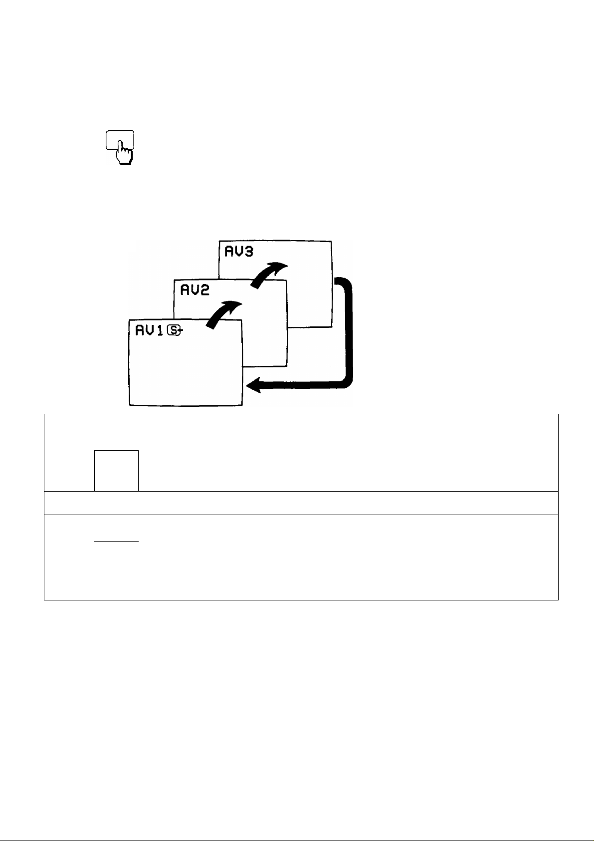
Select the “AV1” mode by pushing this button, you can sequentially
select three AV modes, as shown below.
Note:
When the S-Video cable is
connected to AV1 (S-Video)
Terminal, the “S-Video” symbol will
be displayed on the screen as
shown left.
3.
PLAY
Push the “PLAY” Button on the Connected Equipment.
to
Helpful Hint
SYSTEM System Button
I (11
T3
Note:
(1) When AV mode (AV1, AV2 and AV3) is selected and the selected AV mode has no AV signal, the
On-screen will be changed from Black out picture to Colour back picture.
(2) When the played back picture may be unstable, then by pushing “Play” Button you can obtain
the clear picture.
(3) When the S-Video cable is connected to S-Video Terminal, Input Terminal will be changed from
Video to S-Video Terminal.
(4) When the Monaural VCR is played back. Connect the Monaural Audio cable to the Audio “L”
(Left) Terminal.
On the AV mode, If the clear picture cannot be obtained even when the
AV signal is received, push the System Button repeatedly until the
optimum image can be produced.
F^r operation details, refer to “System Select Operation” on page 49.
21
Page 22
Connection
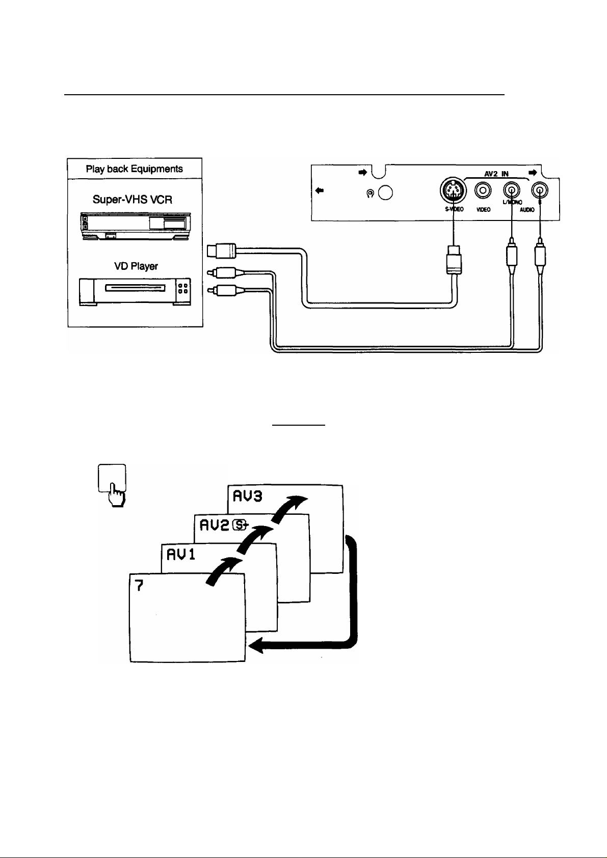
Pattern 2: Via the “AV2” S-Video and Audio Tenninals
Connect the “AV2” (S-Video and Audio) Terminals and Other Equipments as follows.
AV2 Seiect Operation on the TV set
1.
2.
TV/AV
PLAY
Select the “AV2" mode by pushing this button, you can sequentially
select TV and three AV modes (AV1, AV2 and AV3), as shown below.
Selecting mode will appear on the top left of the screen.
Push the “PLAY” Button on the Connected Equipment.
Note:
When the S-Video cable is connected to
AV2 (S-Video) Terminal, the “S-Video”
symbol will be displayed on the screen as
shown left.
22
Page 23
Connection
AV2 Select Operation on the Remote Controller
1.
2.
TV/AV
AV SELECT
Push the “TV/AV” Button on the Remote Controller.
Then last selected AV mode will be displayed on the screen.
Select the “AV2” mode by pushing this button, you can sequentially
select three AV modes, as shown below.
Note:
When the S-Video cable is
connected to AV2 (S-Video)
Terminal, the “S-Video” symbol
will be displayed on the screen
as shown left.
3.
PLAY
Push the “PLAY” Button on the Connected Equipment.
b
Helpful Hint
SYSTEM
Note:
(1) When AV mode (AV1, AV2 and AV3) is selected and the selected AV mode has no AV signal, the
On-screen will be changed from Black out picture to Colour back picture.
(2) When the played back picture may be unstable, then by pushing “Play” Button you can obtain
the clear picture.
(3) When the S-Video cable is connected to S-Video Terminal, Input Terminal will be changed from
Video to S-Video Terminal.
(4) When the Monaural VCR is played back. Connect the Monaural Audio cable to the Audio “L”
(Left) Terminal.
System Button
On the AV mode, if the clear picture cannot be obtained even when the
AV signal is received, push the System Button repeatedly until the
optimum image can be produced.
Fbr operation details, refer to “System Select Operation” on page 49.
23
Page 24

Connection
Pattern 3: Via the “A>^” S-Video and Audio Terminals
Connect the “AV3” (S-Video and Audio) Terminals and Other Equipments as follows.
AV3 Select Operation on the TV set
1.
2.
TV/AV
PLAY
Select the “AV3" mode by pushing this button, you can sequentially
select TV and three AV modes (AV1, AV2 and AV3), as shown below.
Selecting mode will appear on the top left of the screen.
Push the “PLAY” Button on the Connected Equipment.
Note:
When the S-Video cable is connected to
AV3 (S-Video) Terminal, the “S-Video”
symbol will be displayed on the screen as
shown left.
24
a
Page 25

Connection
K/3 Select Operation on the Remote Controller
1.
2.
TV/AV
AV SELECT
Push the “TV/AV” Button on the Remote Controller.
Then last selected AV mode will be displayed on the screen.
Select the “AV3” mode by pushing this button, you can sequentially
select three AV modes, as shown below.
Note:
When the S-Video cable is
connected to AV3 (S-Video)
Terminal, the “S-Video” symbol
will be displayed on the screen
as shown left.
3.
PLAY
Push the “PLAY” Button on the Connected Equipment.
Helpful Hint
SYSTEM System Button
On the AV mode, if the clear picture cannot be obtained even when the
AV signal is received, push the System Button repeatedly until the
optimum image can be produced.
For operation details, refer to “System Select Operation” on page 49.
Note:
(1) When AV mode (AV1, AV2 and AV3) is selected and the selected AV mode has no AV signal, the
On-screen will be changed from Black out picture to Colour back picture.
(2) When the played back picture may be unstable, then by pushing “Play” Button you can obtain
the clear picture.
(3) When the S-Video cable is connected to S-Video Terminal, Input Terminal will be changed from
Video to S-Video Terminal.
(4) When the Monaural VCR is played back, Connect the Monaural Audio cable to the Audio “L”
(Left) Terminal.
25
\
Page 26

Connection
J
Pattern 4: Via the “AVI” Video and Audio Terminals
Connect the “AVI” (Video and Audio) Terminals and Other Equipments as follows.
Equipments
VHS Compact Movie Camera
VHS Movie Camera
Home Computer
AVI Select Operation on the TV set
1.
2.
TV/AV
PLAY
Select the “AV1” mode by pushing this button, you can sequentially
select TV and three AV modes (AVI, AV2 and AV3), as shown below.
Selecting mode will appear on the top left
of the screen.
26
Push the “PLAY” Button on the Connected Equipment.
Page 27

Connection
AV1 Select Operation on the Remote Controller
1.
TV/AV
Push the “TV/AV” Button on the Remote Controller.
Then last selected AV mode will be displayed on the screen.
3.
PLAY
Push the “PLAY” Button on the Connected Equipment.
0
Helpful Hint
SYSTEM System Button
On the AV mode, if the clear picture cannot be obtained even when the
AV signal is received, push the System Button repeatedly until the
optimum image can be produced.
I=br operation details, refer to “System Select Operation” on page 49.
Note:
(1) When AV mode (AV1, AV2 and AV3) is selected and the selected AV mode has no AV signal, the
On-screen will be changed from Black out picture to Colour back picture.
(2) When the played back picture may be unstable, then by pushing “Play” Button you can obtain
the clear picture.
(3) When the S-Video cable is connected to S-Video Terminal, Input Terminal will be changed from
Video to S-Video Terminal.
(4) When the Monaural VCR is played back, Connect the Monaural Audio cable to the Audio “L”
(Left) Terminal.
27
Page 28

Connection
Pattern 5: Via the “AV2” Vide6 and Audio Terminals
Connect the '‘AV2" (Video and Audio) Terminals and Other Equipments as follows.
Equipments
VHS Compact Movie Camera
S-VDEO VNEO
AV2 IN
vil (i
L/I3N0
AUnO
1-'—
—
—
—Í
<n>=
^
---------------
f-n 1—,
'-M
___
1
AV2 Select Operation on the TV set
1.
TV/AV
Select the “AV2” mode by pushing this button, you can sequentially
select TV and three AV modes (AVI, AV2 and AV3), as shown below.
Ht
Selecting mode will appear on the top left
of the screen.
28
PLAY
Push the “PLAY” Button on the Connected Equipment.
X
Page 29

Connection
AV2 Select Operation on the Remote Controller
1.
2
TV/AV
Push the “TV/AV” Button on the Remote Controller.
Then last selected AV mode will be displayed on the screen.
3.
PLAY
Push the “PLAY” Button on the Connected Equipment.
—fc-
o
Helpful Hint
SYSTEM
Note:
(1) When AV mode (AV1, AV2 and AV3) is selected and the selected AV mode has no AV signal, the
On-screen will be changed from Black out picture to Colour back picture.
(2) When the played back picture may be unstable, then by pushing “Play” Button you can obtain
the clear picture.
(3) When the S-Video cable is connected to S-Video Terminal, Input Terminal will be changed from
Video to S-Video Terminal.
(4) When the Monaural VQR is played back, Connect the Monaural Audio cable to the Audio “L”
(Left) Terminal.
System Button
On the AV mode, if the clear picture cannot be obtained even when the
AV signal is received, push the System Button repeatedly until the
optimum image can be produced.
For operation details, refer to “System Select Operation" on page 49.
29
\
Page 30

Connection
Pattern 6: Via the “AV3” Video and Audio Terminals
Connect the “AV3” (Video and Audìò) Terminals and Other Equipments as follows.
Equipments
VHS Compact Movie Camera
<ZJ3
<Z)>
AV3 Select Operation on the TV set
1.
TV/AV
Select the **AV3” mode by pushing this button, you can sequentially
select TV and three AV modes (AVI, AV2 and AV3), as shown below.
I S-VBKI
AVI
IN
MONO
INT.inP [EXT.
HONITOfl
EXT.SP.(80)
OUT
I M®
^ SURROUND OUT
2.
Selecting mode will appear on the top
left of the screen. -
PLAY
Push the “PLAY” Button on the Connected Equipment.
30
\
\
Page 31

Connection
Select Operation on the Remote Controiler
1.
2.
TV/AV
AV SELECT
Push the “TV/AV” Button on the Remote Controller.
Then last selected AV mode will be displayed on the screen.
Select the “AV3” mode by pushing this button, you can sequentially
select three AV modes, as shown below.
3.
PLAY
Push the “PLAY” Button on the Connected Equipment.
o
Helpful Hint
SYSTEM
Note:
(1) When AV mode (AV1, AV2 and AV3) is selected and the selected AV mode has no AV signal, the
On-screen will be changed from Black out picture to Colour back picture.
(2) When the played back picture may be unstable, then by pushing “Play” Button you can obtain
the clear picture.
(3) When the S-Video cable is connected to S-Video Terminal, Input Terminal will be changed from
Video to S-Video Terminal.
(4) When the Monaural \^R is played back, Connect the Monaural Audio cable to the Audio “L”
(Left) Terminal.
System Button
On the AV mode, if the clear picture cannot be obtained even when the
AV signal is received, push the System Button repeatedly until the
optimum image can be produced.
F=br operation details, refer to “System Select Operation” on page 49.
31
Page 32

Connection
Pattern 7: Via the “Monitor Out” Terminals
Connect the '‘Playback” Equipment and “Recording” Equipment via the TV set as follows.
“Monitor Out” Terminals contain signals which are on the TV screen at that time, e.g. TV
programmes or signais from AVI, AV2 or AV3 input.
Operation
Select the desired AV mode,
1.
in this case, select the AV3 mode.
For Operation details refer to page 52 or 66.
Push the “PLAY” Button on the Connected Equipment.
2.
32
Page 33

Connection
Connecting the Headphones
1 • Connecting the headphones as follows.
J
When the Headphones plug is inserted into the Headphones jack, no sound is heard from the
speakers, and you can listen with the Headphones only.
33
Page 34

34
\
\
Page 35

Connection
V
___:_____________________________________^______
Connecting the Surround Speakers
1 ■ Connecting the surround speakers as follows.
-------------
/
(Optional)
AV surround effect is further enhanced upon connecting surround type speakers
Although it is possible to enjoy the “AV Surround Effect“ with this unit alone, upon connecting separate
“Surround Speakers“ the presence of the enveloping sound becomes more vivid.
Place the surround speakers as shown left.
Note:
For Surround Operation details, refer to page 62 to 65.
Speaker
Position
Speaker
Position
35
Page 36

Tuning Procedure (Automatic Search)
This TV set will search automatically through all of the VHF and UHF bands.
After completion, the best tuning position is automaticaily memorized on each Programme Number.
(TV set must be turned on.)
1.
PRE.
(1)(2) (3)
1 1
T
1 ,
CH-J
TUNE I
, UHF-L
?
}-(4)
Push the "PRE." (PRESET) Button until the on-screen display appears as
shown below.
(1) Programme Position Number
(2) Name Write
(3) Band
(4) Tuning bar
36
Page 37

Tuning Procedure (Automatic Search)
2.
1
CH_-
TUNE
AUTO
FUN^DN
Search
UHF-L
Push the “Auto Function” Button.
1
CH--
jPanas on I c
TUNE
UHF-L
The best tuning Search for the
position is auto- next station
matically memorized
\ *0 * /
- CH-- "■
y 1 I s
I I
UHF-L
3. PRE.
Return the TV set to the normal operation mode
by pushing this button twice.
A maximum of 30 channels can be programmed.
Helpful Hint
{1) If you need the station name on the screen display together with Programme Position, for operation
details, refer to the Name Writing operation on page 44 to 45.
(2) After all stations are tuned, Push the Programme Number “Up” Button to confirm the tuning condition
for each Programme Position, If Programme Position is undesired, it possible to skip the Programme
Number, refer to the Programme Number skip operation on page 46 to 47.
37
Page 38

Tuning Procedure (Manual Search)
In case only few TV broadcastings can be received In your area, this Manual Search operation may be preferable.
(TV set must be turned on.)
1.
PRE.
Push the “PRE” (PRESET) Button until the on-screen display
appears as shown below.
(1) Programme Position Number
(2) Name Write
(3) Band
(4) Tuning bar
—(4)
38
Page 39

Tuning Procedure (Manual Search)
2.
3.
V
upward Search
1
CH
__
TUNE
Search
1
UHF-L
Push either the Programme Number Up “ A ” or Down “ V ” Button to
select the desired Programme Number on which you want to tune the
TV station of your choice.
Push either the Level Adjust Up “+” or Down Button, the TV
station broadcasting on the next higher or lower frequency will be
automatically tuned and memorized.
1
CH
__
Panason i c
TUNE
The best tuning
position is auto
matically memorized
UHF-L
If an undesired TV station is received, push the same button again until
the desired TV station is tuned.
4.
PRE.
Repeat steps 2 and 3 to tune all the available TV stations on the
remaining programme numbers.
Note:
Ensure that a new programme number is set (Step 2) before tuning
the next station.
Return the TV set to the normal operation mode by pushing this button
3 times.
A maximum of 30 channels can be programmed.
Helpful Hint
(1) If you need the station name on the screen display together with Programme Position, for operation
details, refer to the Name Writing operation on page 44 to 45.
(2) After all stations are tuned, Push the Programme Number “Up” Button to confirm the tuning condition
for each programme position. If Programme Position is undesired, it possible to skip the Programme
Number, refer to the Programme Number skip operation on page 46 to 47.
39
Page 40

Fine Tuning Operation
1.3
Under normal reception conditions this function is not used.
However, in areas of poor reception or constant interference, a slight adjustment of the tuning may
improve the picture and sound quality.
(TV set must be turned on.)
1.
PRE.
First push
1 UHF-L
CH—
TUNE
Push the “PRE.” (PRESET) Button third times.
The on-screen display will be changed as shown below.
Second push
UHF-L
- CH——
/| |S
w
Third push
FINE TUNE
6IÒI
___
UHF-L
1 [
40
Page 41

Fine Tuning Operation
2.
3.
1
eg
FINE TUNE
<f=l « I —1 [
AFC OFF symbol
PRE.
Push and hold the Level Adjust Up “ + ” or Down “ - ” Button until
picture and sound are improved.
When the above fine tuning operation has been performed,
the AFC function is deactivated, so that the symbol appears
to the left of the Programme Number.
The on-screen display will be appeared as shown below.
UHF-L
Return the TV set to the normal operation mode by pushing this
button.
Fine Tuning cancel operation
Activating the AFC (Automatic Freguency Control) Function.
If you later want to reset this Programme Number to the automatically tuned condition with activated AFC
function.
(1) Select the programme position conditioned on the AFC off position.
(2) Operate the Tuning procedure (Manual Search), refer to page 38 to 38.
41
Page 42

Tuning the TV set to the VCR
Connection
1. Connect the external aerial to the RF Input Socket on the VCR.
2. Connect the aerial terminal on the TV set to the RF Output Socket on the VCR with the supplied
DIN-DIN Coaxial Cable.
The adjustments described on this page are not necessary, if the VCR is connected to the TV set via the Video/Audio output sockets.
1.
PRE.
Push the “PRE.” (PRESET) Button on the TV set until the on
screen display appears as shown below.
(1) Programme Position Number
(2) Name Write
(3) Band
(4) Tuning bar
2.
Select the “VCR” position by using “0/VCR” Button on the
Remote Controller.
42
Page 43

Tuning the TV set to the VCR
3.
Push the VCR On/Off Button on the VCR to turn the VCR On.
4.
Set the “Test Signal” Switch to “TEST” position on the VCR.
5.
6. PRE,
7.
1
CH —
TUNE
UHF-L
Push the MANU. Down “ ~ ” Button on the TV set, the TV station
broadcasting on the UHF will be automatically tuned and memorized.
Confirm on the TV set that the received test pattern is as shown.
------
T
CH
0 1
__
UH F
0
CH —
UHF
1
jPanason i
1
TUNE
J
___
1 "T
TUNE
I
Note: This test pattern is used on the Panasonic/National VCR only.
Return the TV set to the normal operation mode by pushing this
button 3 times.
Set the “Test Signal” switch to “Off” on the VCR.
The TV is now ready to receive the RF output signal from the VCR.
Helpful Hint
If you want the station name on the screen display together with
programme position, for operation details, refer to the Name Writing
operation on page 44 to 45.
43
Page 44

Programme Name Writing Operation
3.5 1.6
2.5
This function is used, if you want to write the Programme name on each Programme Number.
(TV set must be turned on.)
1
'■ PRE.
First push
1
CH—
UHF-L
Push the "PRE ” (PRES^ Button twice.
The on-screen display will be changed as shown below.
Second push
Jll/
■ CH——
UHF-L
4.5
44
TUNE
...
Page 45

Programme Name Writing Operation
2.
l—J Ly
Select your desired programme number position.
3.
AUTO
By pushing this button, you can select the one of four column as
follows.
FUN^J^N
Each time this button is pressed, the next column will be selected
and flashing.
^lli/ UHF-L
■ CH——
4.
Select your desired character by pushing these buttons.
Each time “ + ” Button is pushed, the character will be changed
as follows.
5.
6.
PRE.
0-1
-2
..........
t _, I
Each time " - " Button is pushed, the character will be reverse
changed.
Repeat steps 2 through 4 to the remaining programme positions.
After the name writing operation is finished, Push the “PRE.”
(PRESET) Button twice.
a-9-A-a...............X-Y-Z
45
\
Page 46

Programme Number Skip Operation
1.5
This function makes it possibie to skip the programme numbers on which no TV station are tuned.
This function is oniy effective when seiecting TV station by pushing the programme number Up or
Down Button either on the TV set or the Remote controiier.
(TV set must be turned)
1.
PRE.
Push the “PRE." (PRESET) Button twice.
The on-screen display will be changed as shown below.
a
Second push
UHF-L
. CH„—
/| ,N
1
CH—
TUNE
First push
UHF-L Jll/
46
Page 47

Programme Number Skip Operation
2.
V
Ly Select a programme number you want to skip.
3.
Push the Button.
The on-screen display will be changed as shown below.
Jll/
. CH__—
4.
5.
PRE.
UHF-L
shtx
- SKIP—
"1 1'"
Repeat steps 2 and 3 to remaining undesired programme position.
After the skip operation is finished, push the “PRE." (PRESET)
Button twice.
UHF-L
The “SKIP” Indicator will be appeared.
Then Skip function is set on a programme
position.
How to cancel the skip function.
Method:
1. Push the “PRE." (PRESET) Button twice.
Refer to Step 1 on page 46.
2. Select the skipped programme number by using programme number “Up” or “Down” Buttons.
Refer to Step 2 on this page.
3. Push the Button.
The on-screen indicator will be changed from “SKIP” to “
Then skip function will be canceled.
4. Repeat steps 2 and 3.
5. Push the “PRE.”tPRESET) Button twice.
--------------
”.
\
47
Page 48

Basic Operation on the TV Set
Setting TV stations as follows
1
Power indicator
V
1.
o
SYSTEM
DtSPLAY
TV/AV
+ V A
I* II ^ Power on/off operation
0= [ I =: Push this Button to turn the TV set on.
-i- II II Power indicator will light up.
However, on-screen display does not appear, then push
the Programme Number “Up” or “Down" Button.
AUTO
FUNCTION
PRE.
o
48
Note:
Selection” Buttons (0—9) and Programme Number Up
and Down Buttons on the remote controller.
Page 49

Basic Operation on the TV Set
2.
Programme Number Up/Down Operation
Push the Programme Number Up “a” Button to select the higher
4j
3.
programmes.
Push the Programme Number Down “v” Button to select the lower
programmes.
Volume Up/Down Operation
The sound level can be adjusted in steps.
Push the Volume Up “ + ” Button to increase the sound level.
Push the Volume Down “ - " Button to decrease the sound level.
On-screen display will appeared as shown left.
4.
UOLUtlE
^12
SYSTEM
System Select Operation
This Button is used only AV mode. Normally, the System Switch is
automatically set to the Auto Mode on the AV mode. If the clear
picture cannot be obtained even when the AV signal is received, push
the “System” Button repeatedly until the optimum image can be
produced. The colour back will be changed as shown below.
49
Page 50

General Operation on the TV Set
Picture and Sound Control
Picture and Sound have been set according to a factory-preset levels.
You can change these setting according to your desired level.
However you can change only last function menu on before standby enabled. When you want to set
the other menu, use the **Picture Menu” Button or “Sound Menu” Button on the remote controller.
1.
AUID
By pushing the “Auto Function” Button, the on-screen display will
FUN^DN
appear.
50
Page 51

General Operation on the TV Set
51
Page 52

General Operation on the TV Set
1
1.
TV/AV
T3
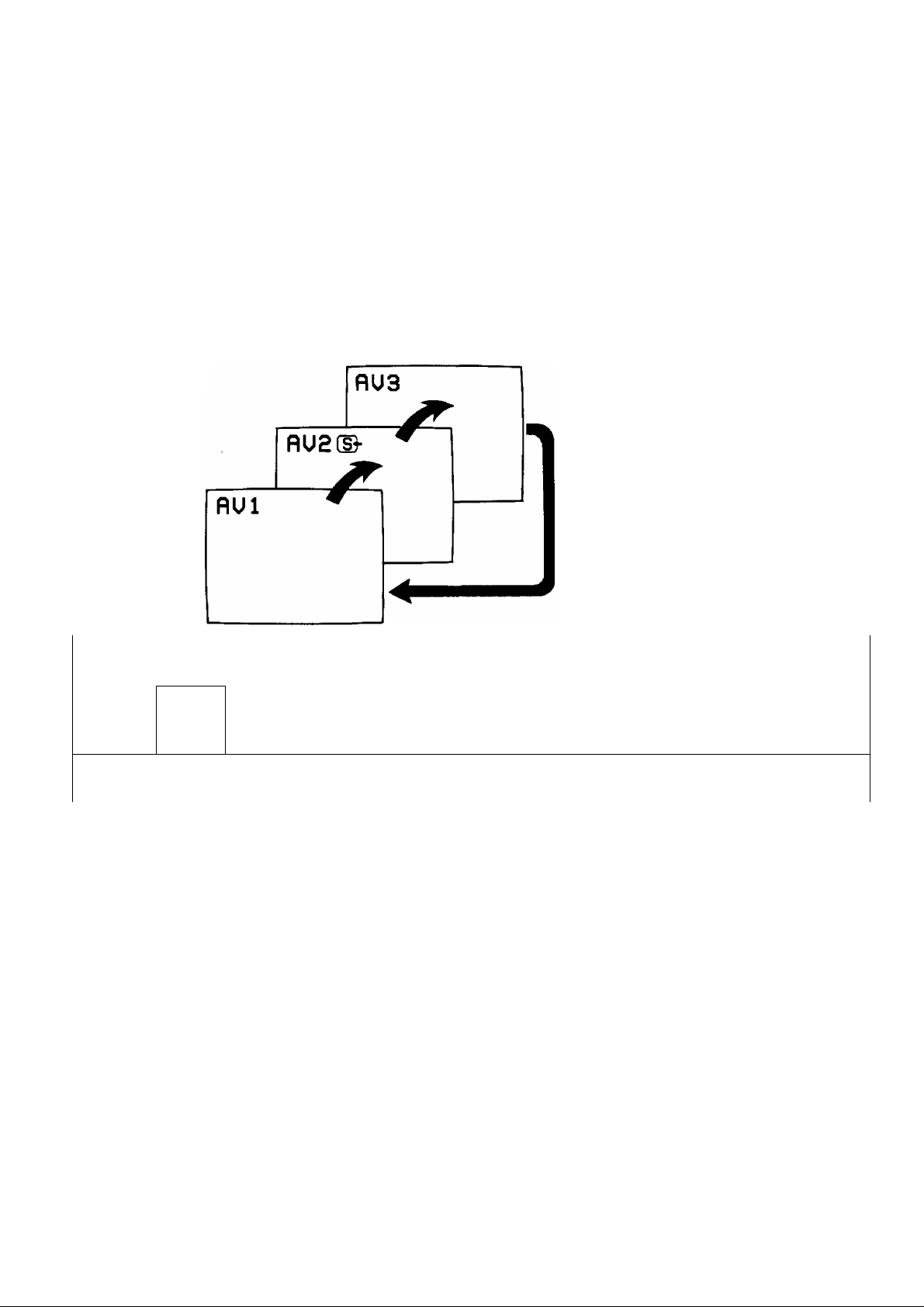
AV modes (AV1, AV2 and AV3) Select Operation
Push the “TV/AV” Button to select the TV and three AV modes
(AV1, AV2 and AV3).
By pushing this Button, on-screen will be changed as shown below.
Note:
(1) When AV mode (AVI, AV2 and AV3) is selected and the selected
AV mode has no AV signal, the On-screen will be changed from
Black out picture to Colour back picture.
(2) When TV mode is selected, the last programme number on
before standby will appear on the screen.
52
\
Page 53

General Operation on the TV Set
2.
3.
DISPLAY
T3
a
Actual Channel-
Colour System-
Display Button
Push the **Display" Button, the on-screen display will appear as
shown below.
Programme Position Number
A
■CHIS
PflL
__
I
WHRT a GREHT WRV
TO URTCH TUÜ
{Panasonic I
Push again the “Display” Button, the on-screen display will
disappear.
WITH
^STEREO-
MONO—
AUDIO Mode
Note:
When this button is pushed, the
Picture and Sound menu will change
to Picture 2 and Sound 2. And each
level will be changed to Normal mode.
For Picture and Sound menu details,
refer to Picture and Sound Operation
on Page 58 through 61.
Game Position Button
By pushing the “Game Position” Button, reproduction of irregular
signals such as certain TV games and rental video tapes will be
improved.
This function is effective when the RF IN Terminal is connected.
53
Page 54

Basic Operation on the Remote Controller
/r
□ [a E
B E 0
© © ® © ©
® © ® ® ®
W w mm.
SCIACI
vcn
□
® Ih! S 0 El
^
---
r y
S B El [S-D
The Remote Control can only be used when the “Power” Button is in the on condition.
(The Power indicator on the TV set light up)
1.
Ò
Power (Stand-By) Button
Push this button to turn the TV set on.
Push it again to turn the TV set off.
54
It is able to turn the TV set on by pushing the digit, “Direct
Programme Number Selection” buttons (0-9) and the “Programme
Number Up and Down" Buttons.
Note:
Do not leave the TV set in the stand-by condition for a long period
of time.
It is better to switch it off when you are away for extended period of
time.
\
Page 55

Basic Operation on the Remote Controiier
2.
Programme Number Up/Down Button
Push the Programme Number Up “a” Button to select the higher
A
programme numbers.
3.
4.
V
w
V,
Push the Programme Number Down “v” Button to select the lower
programme numbers.
Voiume Up/Down Button
Push the Volume Up “ + ” Button to increase the sound level.
Push the Volume Down “ - " Button to decrease the sound level.
Programme Number Up/Down Button
One digit programme number
(Programme numbers 0-9)
You can select the numbers 0 to 9 directly.
5.
e.g. Selecting number “7”
Push the "7” Button.
Two digit programme number
(Programme numbers 10-29)
e.g. Selecting number “24”
Push the Button.
The on-screen will be displayed as follows.
Push the "2” Button.
Push the “4” Button.
55
Page 56

NICAM Digital Stereo Reception
When a stereo, dual-soundtrack or monaural NICAM programme is being received, the on-screen
indicates to inform you of the type of broadcasts.
1.
avv
NICAM Sound Selection Button
Sound output can be selected by pushing “Sound Selection” Button.
Note:
If the stereo signal is weak or the receiving condition extremely poor,
it is recomendable to switch to the "Mono” Mode.
56
Page 57

NICAM Digital Stereo Reception
Type of broadcast
Regular broadcast
(Standard Audio)
Regular
+
NICAM MONO I
(MAIN (I))
On-screen indicator
«♦MfliNi I ;
MONO
MfliNc1 ;
■»MONO
Remark
Normal use
You can select either
of the “MAIN <t)/
MONO".
STEREO
#MONO
You can select either
of the “STEREO/
MONO".
Regular
+
NICAM STEREO
■»STEREO
MONO
Regular
+
NICAM DUAL MONO
(MAIN m
►MfliNU :
suB(s ;
MONO
You can select either
of the “MAIN <I), SUB (II)
or MONO".
Notes.
1. When the power is set ON, the mode is pre-set at "MAIN(I)/STEREO”.
2. Even when the contents of the receiving signal undergo changes, selection mode is kept intact.
3. When the receiving-conditions deteriorate, listening will be easier if the STANDARD AUDIO Mode
is set at “MONO” position.
\
Page 58

Picture Menu Operation
1
n d] &
^ jjp
O©® ©(D
|) 0 ® ® ®
souw
SELECT
□
5 S El E]
6
------,------------
0 B S ffl“D
VCR
m
0
2
3
3 menues can be selected to match the TV with the watching environments and/or the visual softwa res
“COLOUR”, “NTSC-TINT’, “CONTRAST’, “BRIGHTNESS” and “SHARPNESS” are memorized into each
menu: letting you tailor the visual effect of your favorite picture.
(The level is preset at the factory.)
Menu select operation
1.
PICTURE
MENU
f I
PICTUREl (STANDARD)
By pushing this button, you can sequentially select three picture menu
(^ANDARD, DYNAMIC and MILD), as shown below.
PICTURES CtlILD)
CDVNflMIC)
PICTURE 3 (MILD)
For watching at moderately dark
places. It is set at pictures where
consideration is given to dark scenes.
PICTURE 2 (DYNAMIC)
For watching at bright places, it is set at
modulated picture where contrast effect
is strongly felt.
PICTURE 1 (STANDARD)
For watching at standard brightness, it
is set at standard picture.
58
Page 59

Picture menu operation
To Adjust the Picture menu
1.
PICTURE
MENU
PICTURES (MILII)
PICTURES CDVNflMIC)
PICTUREl iSTRNDflRm,
2.
%
PICTUREl (STANDARD)
COLOUR
tA)3S NTSC-TINT
■i>32 BRIGHT
3 40
CONTRAST
CD3E SHARPNESS
(e.g. Selecting the “PICTURE 1“ menu)
By pushing this button, you can sequentially select three picture
menu as shown below.
For each picture menu, the function leveis shown below
can be adjusted.
Select your desired function. By pushing the “P” Button sequentialiy,
the on-screen display appears as shown below.
COLOUR-
L_
■NTSC-TINT-^BRIGHT-^CONTRAST
------
SHARPNESS
----------------
1
Note:
NTSC-TINT indicator.
When the system button on AV mode to select
the “NTSC4.43” or “NTSCaSS”, NTSC-TINT”
indication will be displayed on the screen.
3.
4.
Helpful Hint
5.
PICTUREl (STANDARD)
932 COLOUR
NTSC-TINT
ttl>32
BRIGHT
iCi-SE
347 CONTRAST
0)32 SHARPNESS
NORMAL
(e.g. Selecting the “COLOUR” function)
By pushing the “+” Button or Button, the on-screen display
will be changed the level indicator as shown left.
Push the “+” Button to increase the level of selected function.
Push the Button to decrease the level of selected function.
Repeat steps 1 through 3 to the remaining picture menu.
By pushing this button, the selected menu will be changed to the
Normal mode.
The on-screen will appears as shown below.
-
59
Page 60

Sound Menu Operation
60
\
Page 61

Sound Menu Operation
To Adjust the Sound menu
1.
SOUND
2.
Select your desired function, By pushing the “S” Button sequentially,
the on-screen display appears as shown below.
----------------------------------------
By pushing this button, you can sequentially select three
sound menu as shown below.
For each sound menu, the function levels shown below
can be adjusted.
SOUNDS (MUSIC)
7 45 BBSS
4 45 TREBLE
4.
Helpful Hint
BASS->TREBLE-» BALANCE
t
______________
BALANCE
h.4 32 [,, -n 1
(e.g. Selecting the “BALANCE” function)
By pushing the “+" or Button, the on-screen display will be
changed the level indicator as shown left.
Push the V Button to increase the level of selected function.
Push the Button to decrease the level of selected function.
Repeat steps 1 through 3 to the remaining sound menu.
.
] J
I
5.
SOUNDS (MUSIC)
n 46
BASS
SO
TREBLE
NORMAL
OR
By pushing this button, the selected menu will be changed to the
Normal mode. The on-screen will appears as shown below.
on-screen for BALANCE
level: 32 (center position)
BALANCE
^^32r-"" □ 1— =>
level bar: Red
61
Page 62

Surround Operation
1
■Ir^]
mm ufotfc
□ ja [S] [gl
O© ® © ©
® © © ® ®
□
S tal B 0 E)
0
---
f—e
H S B 00“D
E B
VCR
1.
SURROUND
4y
AV Surround Sound
The benefits of surround sound are enormous. With additional
speakers you can be completely enveloped in sound—just as if you
were at a concert hall or cinema. We also provided a surround level
control—so you can adjust the effect to suit your taste.
The on-screen will be changed as shown right.
Note;
When the “Movie” or “Mono” surround is selected, the Extra Bass
System will set on automatically. When the Extra Bass System is
activated, the Dynamic low frequency ranges are boosted.
‘'Extra Bass System”
The Extra Bass System effect may be different according to the
Programme content of the music source.
62
Page 63

Surround Operation
Type of broadcast
• Regular
• Regular
+
NICAM MONO I
• Regular
+
NICAM DUAL
MONO
o>
■o
o
>
H
• NICAM
STEREO
MONO SURROUND
); ; Nc : c c
On-screen
t
tIOUlE SURROUND
>)> <
MUSIC
SURROUND
c
SURROUND OFF
Remark
You can select
either of the
surround
“MONO/OFF”.
You can select
either of the
surround **MOVIE/
MUSIC/OFF".
Note:
Mono surround
can not select.
?
S
o>
Select the AV
Modes.
(AVI, AV2 and
AV3)
MOUIE SURROUND
) )► MU
SURROUND OFF
-
MUSIC SURROUND
)))Mi U C
You can select
either of the
surround “MOVIE/
MUSIC/MONO/
OFF”.
MONO SURROUND
)))>► M(C <(
63
\
Page 64

Surround Operation
“iC
1
mBSSB
[|l E) [0
Q IÉD SI
© © <D © ®
© 2 ® ® ®
□ la
il) la B 0 Ei
9—^—e
SOS ffl“D
To Adjust the Surround Level
--
3
2
vcn
2
1.
2. □
nOUIE SURROUNO
iifli < C C
nOUIE SURROUND
SURROUND
T3
By pushing this button, you can sequentially select the Surround menu.
Surround details, refer to page 62 to 6S
(e.g. Selecting the “MOVIE SURROUND” menu.)
By using the “ + ” Button or “ - ” Button, you can select the desired surround
level.
Push the “ + ” Button to increase the level of selected menu.
Push the “ - " Button to decrease the level of selected menu.
64
Page 65

Surround Operation
V
__-_______-_ ______________
\
Helpful Hint
-
------------------------
j
3.
By pushing this button, the selected menu will be changed to the Normal
Surround level.
?)
65
Page 66

General Operation on the Remote Controller
1.
2.
TV/AV
AV SELECT
Push the “TV/AV" Button on the Remote Controller.
Then last selected AV mode will be displayed on the screen.
By pushing this button, you can sequentially select three AV modes as
shown below
J
Note;
When AV mode (AV1, AV2, and AV3) is selected and the selected
AV mode has no AV signal, the on-screen will be changed from Black
out picture to Colour back picture.
66
Page 67

General Operation orr the Remote Controller
3.
Push the “Mute” Button to mute the sound.
Push this button once to mute the sound 50%.
The on-screen display will appear as follows.
The previous sound level wilt appear in yellow.
The “Mute” symbol will be remained.
«
Push this button again to mute the sound perfectly.
The previous sound level will appear in red.
The “Mute” symbol will be remained.
4.
«
Push this button once again to restore the previous
sound level.
Note:
In the “Mute” condition, you can use the Volume “Down” Button.
Using the Volume “Up” Button, the “Mute” will be canceled.
Push the “Recall” Button to activate the on-screen display as below.
Programme Position
Number
Actual Channel
Colour System Sound menu —
---------------
Sound System Picture menu
RNRon or off
Surround Mode-
Push again to cancel.
— 4
-CHte
-PflL
'S.SMHz
-SOUNDS
-PICTUREl
-P NR ON
-►MONO SURROUND^SSO-
♦ STEREO-
MONO -
AUDIO
Mode
■ - off timer
The Programme
Number and Actual
Channel will be
remained.
67
Page 68

Generai Operation on the Remote Controller
^ poi
1
-----------
il - wm ftOTve«
—□ □ E] S)
-I-
____
— —;
!
^ B E B
©CD ® © ®
§ g © ® ©
1.
SEUCT
□
S 0 B 0 s
©---------1—
[S B B iS"D
VCR
IS
=t
Off Timer Button
The TV set may be pre-set to switch off after a fixed period.
Pushing the “Off timer” Button will set the TV for 30 minutes.
To set 60 minutes, push this button again, and again for 90 minutes.
Pushing this button once more will return the Pre-set time to zero.
30- 60-90-0
Í
__________
I
68
When a time for switch off has been set, the pre-set time will be displayed as
follows. (e.g. setting for 30 min)
And rest time is displayed on-screen.
After
6 min.
-
ED30
-----
■ —
\
Page 69

General Operation on the Remote Controller
Note: Pre-set time may be cancelled in the Ibllowing ways.
1: Set the Pre-set Time condition to “0” using the “Off timer” Button.
2: Turning the TV set off, using the “Power” Button on the Remote
Controller or the “Power” Button on the TV set.
When it will be 3 minutes before the time for switch off, the display of
rest time will begin to flash.
J
2.
PNR
a
Picture Noise Reduction Button.
The Picture Noise Reduction system is a system designed to effectively
reduce the Picture Noise.
The on-screen display will be appeared as follows.
The Picture Noise Reduction is ON condition.
The Picture Noise will be soft.
P-NR ON
The Picture Noise Reduction is OFF condition.
The Picture Noise will be sharp.
On the channel of the weak broadcasting signal or no signal, the on
screen will be Blue back picture and the noise will be muted
automatically.
Note:
When you want to watch the weak broadcasting in spite of the
disturbance, turn the Picture Noise Reduction to ON condition. Then
the TV will be able to receive the weak broadcasting.
69
Page 70

Operation for VCR
This infrared remote control is designed specifically to be used with selected Panasonic/National VCRs.
Some model VCRs have different functions, so please refer to the individual instruction booklet to ensure
compatibility when using this remote control with Panasonic/National VCRs, consult your dealer for details.
r
□ ms
E] □
B [B a
©© ® ®
2 ® ® ®
1.
2.
3.
4.
SOUND
SELECT
!)
Sound select Button for VCR
You can select the Sound mode (Stereo or Bilingual), by pushing this
button.
Sound select operation details, refer to operating instructions of the VCR.
Pause/Still Button
Push to stop the tape temporarily during playback.
A still-picture will be shown.
Stop Button
Push this button to stop the tape.
Rew (Rewind)/Review Button
Push this button to rewind the tape.
During the playback mode, holding this button down will allow you to
view the picture in reverse rapidly. (Review)
70
\
Page 71

Operation for VCR
5.
VCR
"ól
7.
Play Button
Push this button to playback the tape.
VCR Power Button
Push this button to turn the VCR on.
Push again to turn off.
8.
9.
0
Stilt Advance Button
While in the still mode, push this button to advance the picture
one frame at a time.
Programme Number Up and Down Buttons for VCR
Push the Programme Number “Up” or “Down” Button to select a
programme position which you want to tune to a TV station.
Rec (Record) Buttons
Recording is started by pushing these 2 buttons at the same time.
10.
FP (Fast Fbrward)/Cue Button
Push this button to fast fonvard the tape.
During the playback mode, holding this button down will allow you to
view the picture in the for\A^ direction rapidly. (Cue)
71
Page 72

Warnings and
%
T ' *
I
Power Source and TV System
This TV set can be operated on AC 230 V 50 Hz.
It is designed exclusively for broadcast systems PAL B. G.
To prevent damage which may result in fire or electrical shock hazard, do
not expose the TV set to rain or excessive moisture.
[ "
V
High Voltage:
Do not remove the rear cover as live parts are accessible when it rear
cover is removed.
Adequate ventilation is essential to prevent failure of electrical
components.
Avoid exposing the TV set to direct sunlight and other sources of heat.
Remove the plug from the wall outlet (Power point) when the TV set is
not used for a prolonged period of time.
72
A\
1
TT k
i'i*:
ife-
'ft
Cabinet and Picture Tube Care
The cabinet and picture tube can be kept in good condition by simply
wiping with a clean, soft cloth moistened with mild detergent and water.
Do not use solutions containing benzol, petroleum or a chemical cloth.
For safety, remove the plug from the wall outlet.
S
Do not used this set if abnormal operation occurs.
Ex ; Smoke, odd sounds, or smells Turn the power switch off and
disconnect the AC plug, if you notice any unusual operation.
is
\
Page 73

Troubleshooting
Before you call for service, determine the symptoms and make a few simple checks as shown below.
Symptoms
Picture
Snowy Picture
Multiple Image
Interference
Sound
J'j>
\
Noisy Sound
\
Normal Sound
Noisy Sound
Aerial Location, direction
or
Connections
Aerial Location, direction or Connections
Electrical Appliances
Cars/Motorcycles
Fluorescent Lamps
Checks
Normal Picture
No Picture No Sound
No Colour Normal Sound
ass
Scrambled
Coloured Patches
No Sound
Normal or
Weak Sound
Normal Sound
Speaker select switch, Volume
(Check whether the mute function has been
activated on the Remote Control.)
Not plugged into AC outlet
Not switched on
Contrast and Brightness/Volume setting
(Check by pushing the Power Switch or Stand-by
Button on the Remote Control.)
Colour Control
Retune Channels
Magnetic interference from unshielded equipment
Receiver moved while “ON”
(Power switch off for 10 mins.)
\
Noisy Sound
System Button
73
\
Page 74

Specifications
Power Source
AC 230 V. 50 Hz
Power Consumption
200 W
Stand-by condition 11.5 W
Receiving System
4 Systems Function
1
PAL B. G
Reception of broadcasts and
Playback from Video Tape
Recorders
NTSC4.43/5SMHz
2
NTSC358/55MHZ
3
4 PAL60HZ
Receiving Channels
Regular TV
Playback from Special Video
Tape Recorders
VHP BAND
1-11
UHF BAND
21-69
74
Page 75

Specifications
Tuning System
Picture Tube
Headphones
Audio Output
Voltage synthesized
29 inches {72 cm) measured diagonally
110° deflection
Impedance 8(2
Internal Speaker 9W (10°/o distortion), 12W (Max.)
External Speaker 9W (10% distortion), 12 W (Max.)
Aerial Impedance
7512 Unbalanced coaxial
Video/Audio Terminals
AVI, 2,3 S-Video In
Monitor Out
Accessories Supplied
Remote controller x 1
R6 Battery x 2
Dimensions (W x D x H)
Y:1X)Vp-p,75Q
C; 03 Vp-p, 75Q
Video In
Audio in Approx. 400mV
Video Out 1 Vp-p, 75(2
Audio Out
1 Vp-p, 75(2
Approx. 400mV
700mm X 495mm x 577mm
Mass (Weight)
43.0 kg (Net)
Note:
Design and Specifications are subject to change without notice.
Weight and Dimensions shown are approximate.
75
Page 76

Customer’s Record
The serial number of this product can be found on its rear cover. You should note the serial number of
this unit in the space provided below and retain this book as a permanent record of your purchase to
aid in identification in the event of theft or loss.
Model Number TC-29V1Z Serial Number
Matsushita Electric Industrial Co., Ltd.
Central RQ Bc9r288t Osaka 530-91, Japan
\
Printed in Japan
S1190
Page 77

Helpful Hint
VCR Operation
If during the operation in "CUE" or "REVIEW" Mode, a Coloured Screen appears on the television,
the "Picture Noise Reduction" Function needs to be set "On" (PNR ON) by pushing the "PNR" Button
on the Remote Control Handset.
>± )№
n ««REVIEW» ■ -VI «CUE» 4JLm J.i .*.*11 ¿¡jjjiUI <^LlL Ijl
. ¿fC. jUiimI yJlc (PNR) jj yiijiSj cU^j «On» ^^ic. (PNR)
jjJ»
Ju¿*
)) L «Picture Noise Reduction» jm\1í jj¿yijlú *■»■>■* iSjj «REVIEW» L «CUE» CJU. ji jSi
. «Oí» ¿f^jj ifjj^ ‘ JJ^ J ijjj «PNR» jLti U
Операция BM
Полезный совет
Если во время работы в режиме "CUE" (Быстрый просмотр вперед) или "REVIEW" (Быстрый
просмотр назад) на экране телевизора появляется Цветовой фон, то следует установить
функцию "Уменьшение помех на изображении" в положение "ВКЛ." (PNR ON). Для этого надо
нажать.кнопку "PNR" на пульте дистанционного управления.
Pozyteczna rada
Czynnoáci magnetowidu
Jeálí w czasie czynnoáci przegtadu taémy do przodu (“CUE") lub do tyili (“REVIEW”) na ekranie ukaze
si$ kotorowy obraz, nalezy w>t^czyó “Ulclád redukcjì szumów obrazu” (PNR ON) poprzez naciáni^cie
przycisku “PNR” na nadajniku zdalnego sterowania.
Sugerencia Práctica
Operación de VGC
Si durante la operación en la modalidad "CUE" (Localización progresiva) o "REVIEW" (Localización
regresiva) aparece en la pantalla del televisor un color azul, la Función de "Reducción de Ruido de
Imagen" debe activarse, pulsando el Botón "PNR" de su Aparato de Control Remoto.
Sugestáo Útii
Operando do Aparetho de Video Cassete (VCR)
Se durante a operagáo no modo "CUE" ou "REVIEW" aparecer na televisáo urna Teta Colorida,
torna-se necessàrio ligar a Fungáo "Picture Noise Reduction" (PNR ON) Pressionando a Tecla "PNR"
do Dispositivo Manuai de Controle Remoto.
TQB620879-1
 Loading...