

Page 1

Panasonic
Colour Television
TC-26T1Z
Operating Instructions
Please read thiese instructions compieteiy before operating this set
and retain li for future reference.
T0B620846
Page 2

Page 3

Dear Panasonic Customer
Welcome to the Panasonic family of Customers.
We hope that you will have many years of enjoyment from your new
colour television set
Page 4

Table of Contents
Before Operating this Set
Battery Instailation and Repiacement
VCR Mode Seiection
................................................................
....................................................
.................................
$
7
8
Location of Controls for TV Set..............................................10
Location of Controls for Remote Control
For Regular TV Operation...........................................................................................................................12
For VCR Operation..................................................................................................................................... 14
Location of Terminals.............................................................16
How to Connect an Aerial.......................................................18
Automatic Turn-off Function ..................................................19
Connection
Pattern 1 : Via the &-V¡deo and Audio Terminals ......................................................................................20
2: Vie the Video and Audio Termináis ...................................................................................... 22
3 : Via the “Monitor Out" Terminals ............................................................................................24
Tuning Procedure (Automatic Search)
...................................
26
Tuning Procedure (Manual Search)
........................................
28
Fine Tuning Operation .......................................................... 30
Tuning the TV Set to the VCR
Programme Name Writing Operation
Programme Number Skip Operation
.................................................
.....................................
......................................
32
34
36
Page 5

Table of Contents
Basic Operation on the TV Set
General Operation on the TV Set
...............................................
............................................
38
40
Basic Operation on the Remote Control ................................44
Picture Menu Operation
Menu Select Operation ...............................................................................................................................46
To Adjust the Picture Menu.........................................................................................................................47
Sound Menu Operation
Menu Select Operation .............................................................................................................................. 48
To Adjust the Sound Menu......................................................................................................................... 49
General Operation on the Remote Control
............................
50
Operation for VCR...................................................................54
Warnings and Cautions
........
................................................
56
Troubleshooting .....................................................................57
Specifications
.........................................................................
58
Page 6
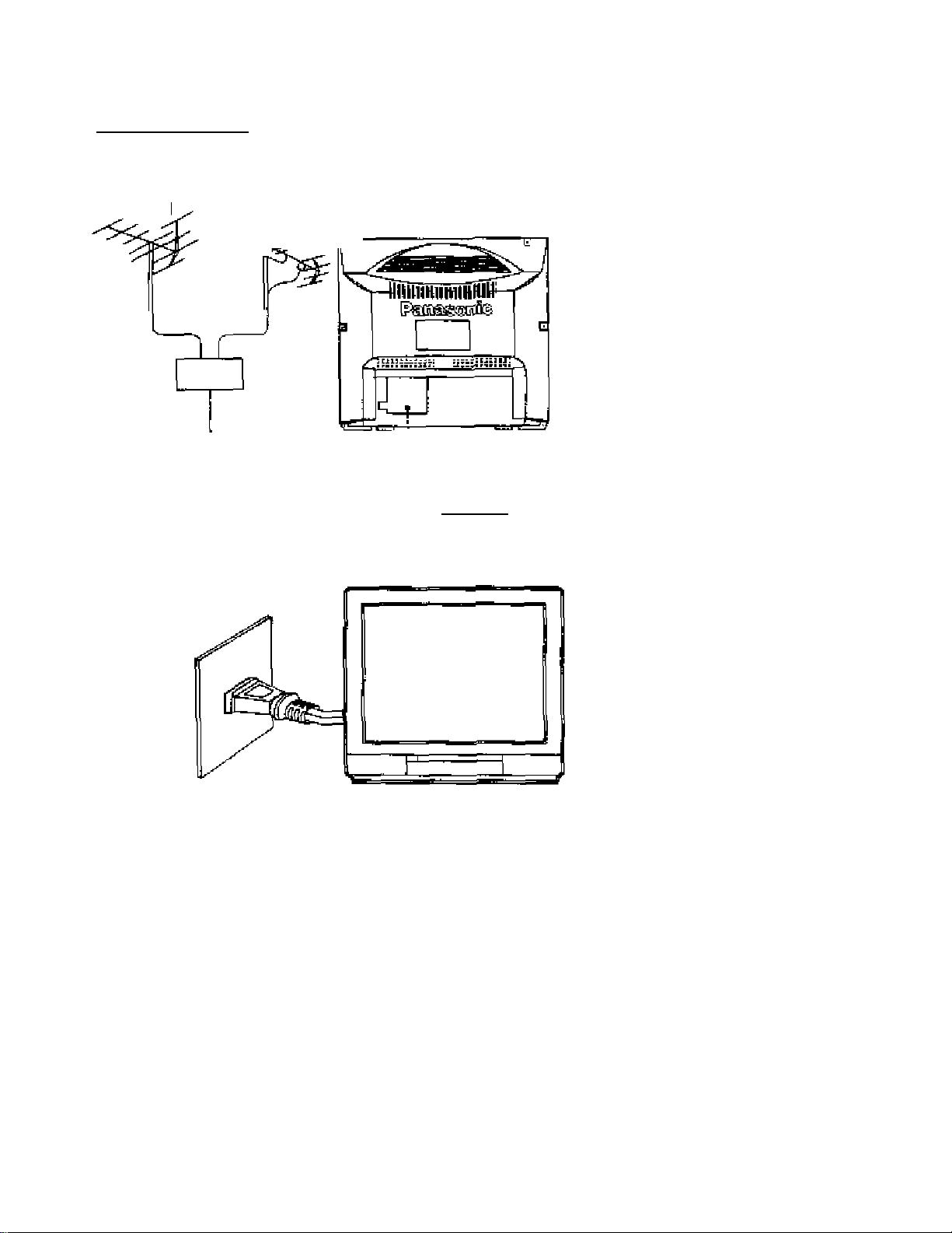
Before Operating this Set
Preparations
Connect the Aerial Cabie to the RF in Terminal
VKF Aeria
Mixer
UHF Aerial
-[2}*' Aerial Plug
Connect the Plug to the vrall outlet
How to connect an Aerial
For connection details refer to page 18.
Connect the AC Plug to AC Outlet
This TV set can be operated or> AC
230 V, 5Û Hz.
For Warnings and Cautions details, refer to page 56.
Note:
Remove the plug from the wetl outlet
when the TV set is not used for a
prolonged period of time.
Page 7
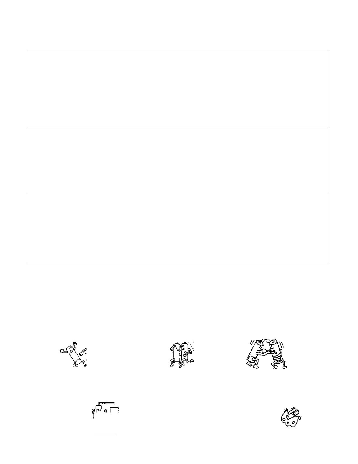
Battery Installation and Replacement
Batteries: Use two “R6" size batteries
1
open the cover.
Push down and remove the cover.
2
Two ''R6" size
Replace the batteries.
Insert the batteries with the correct polarity a$
indicated by the " + and " " symbols,
3 .
Replace the cover.
Do rKt use rechargaabld (Ni-Cd) battenes.
They are partially different in and performance and may fail to ensure the desired function.
Battery precautions
The incorrect use of batteries can cause electrolyte leakage which will corrode the remote control transmrtter
or cause the batteries to burst. The fdlnving precautior^ must be observed carefully.
Old Batterjes New Batteries
I i ,
Reptace tioth batteries at the same time
Dispose of them tmrrediateiy.
Don't
X
Recharge
X
•*=) 5'e.l
Short'Circuit
Ûort't mix battery types
(albalirte with cerbcxi ¿ine, etc.j
X
Disassemble
Pire
X
Heat or Bum
Page 8
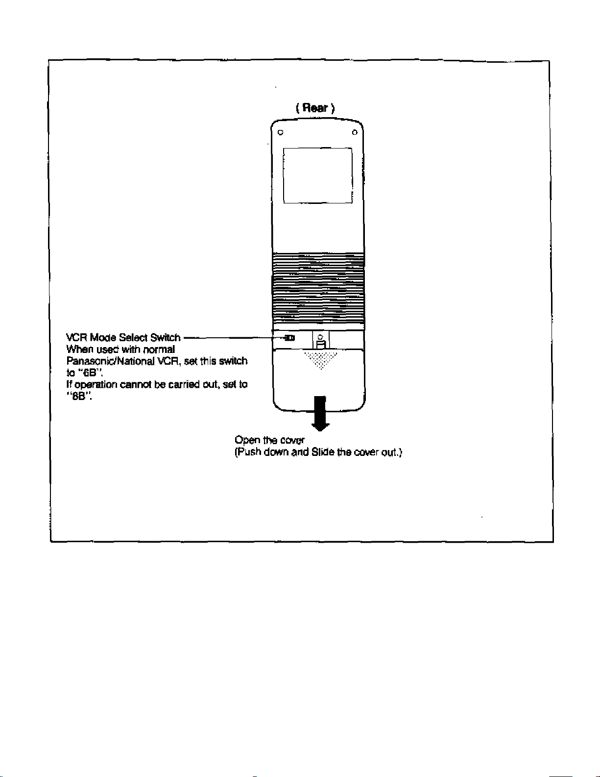
VCR Mode Selection
8
Page 9

Page 10
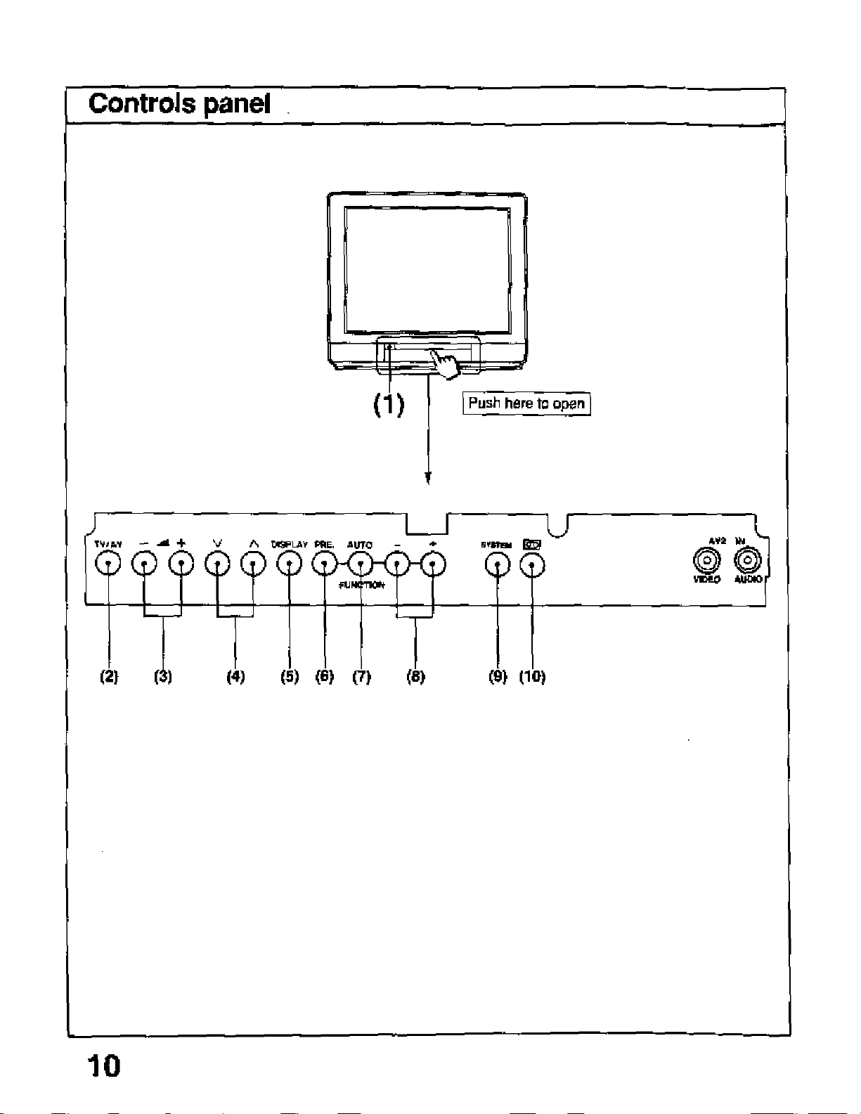
Location of Controls for TV Set
Page 11

Location of Controls for TV Set
^ J
No. Description
i1)
m
(3)
(4)
<5>
(6>
(7)
(8)
w
(10)
Power Switch
TV/AV Sekection Button
Volume Up and Down Buttons
Programme Number Up and Down Buttons
Display Button
Preset Button
Auto/Function Button
Level Adlustment Buttons
System Selection Button (Colour System)
Game Position Button
11
Page 12
Location of Controls for Remote Control
For Regular TV Operation
✓
12
Page 13

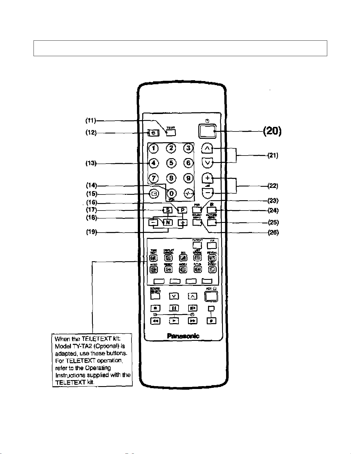
Location of Controls for Remote Control
No. Description
(11) TV/AV Selection Button
(12) Off'Urrier Button
(13) Direct ProgreiTiFne Number Selection Buttons
(14) 0/VCR Button
(15) Recall Button
(16) Picture Function Button
(17) Sound Function Button
(18) Normalisation Button
(19) Function ievei Up end Down Buttons
(20) Power (Stand-by) Button
(21 ) Programme Number Up and Down Buttons
(22) Volume Up and Down Buttons
(23) Picture №>ise Reduction Button
(24) Mute Button
(25) Picture Menu Button
(26) Sour>d Menu Button
13
Page 14
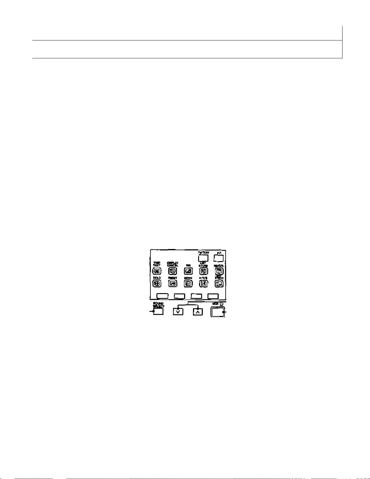
Location of Controls for Remote Control
1 For VCR Operation
B □
© ® ® 0
® ® ® 0
® ® ® 0
J
(27) (28) (29)-
my
(31).
When TELETEXT kil;
Model TY-TA2 (Optional) is
adapited, use these buttone.
For TELETEXT operation,
refer to the Operating
Inetriictlons suppJied with the
TELETEXT kit,
® ® © 0
«
□
□
-(32)
^33)
■(34)
’(35)
-(36)
14
Page 15

Location of Controls for Remote Control
N_________________________________________________________________________________________
J
No.
(27)
(28)
(29) Stop Button
(30) RewIncVReview Button
(31) Play Button
(32)
(33) VCR Power Button
(34)
(35)
(36) Fast Forward Button
Description
Sound 5o№k>n Button for VCR
Pause Still Button
Programine Number Up and Down Buttons for VCR
StiM Advance Button
Record Buttons
15
Page 16
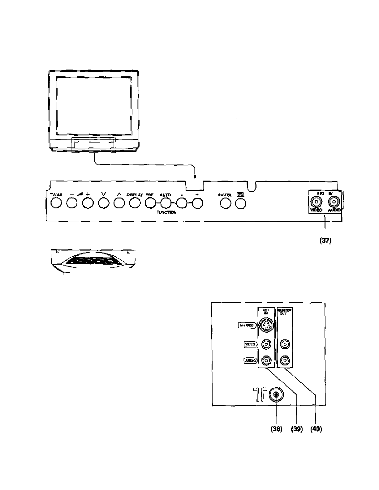
Location of Terminals
Location of Front and Rear Terminals
16
Page 17

Location of Terminals
No. Description
(37) AV2 Input Terminate
(38) Aerial Terminal
(39) AVI Input Terminate
(40) Monitor Output Terminate
17
Page 18
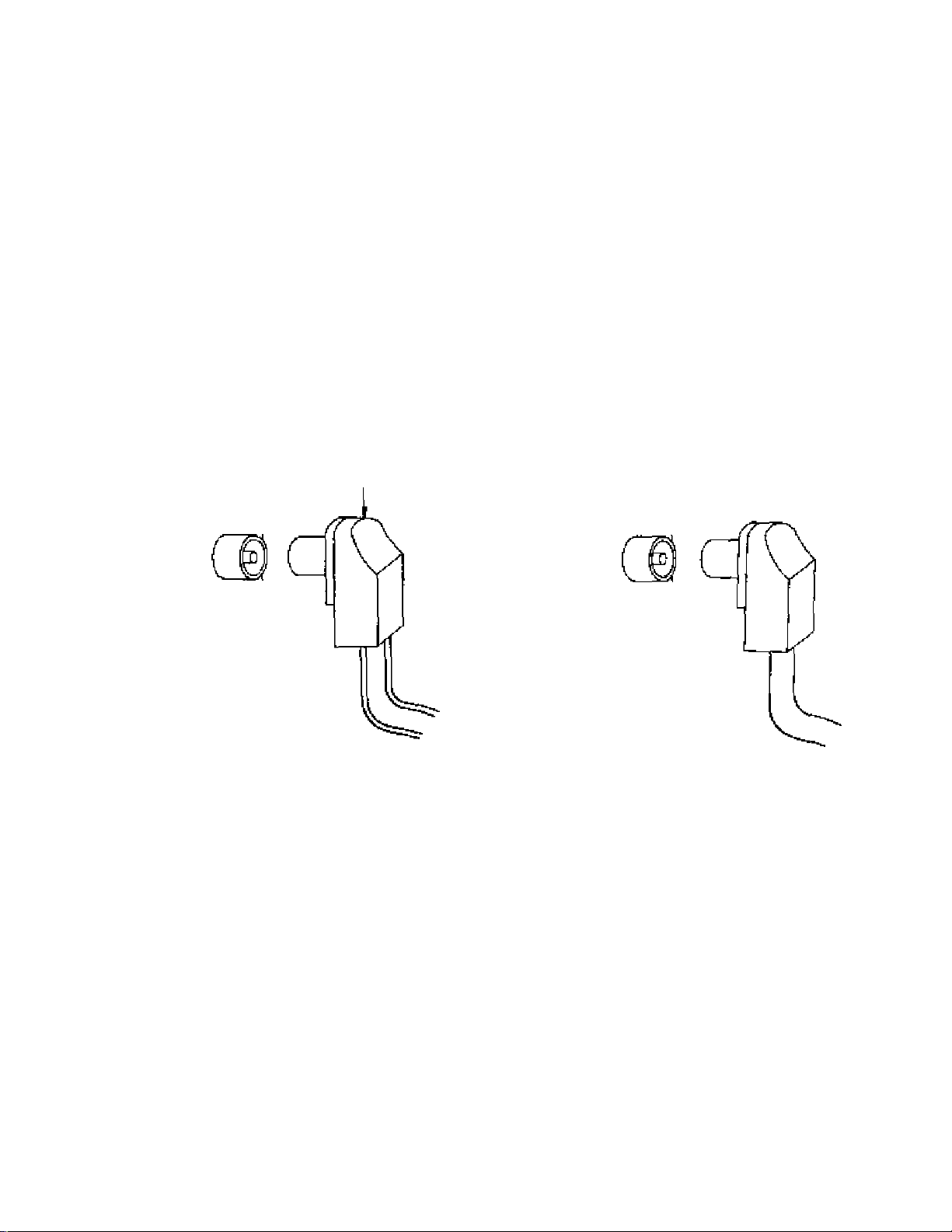
How to Connect an Aerial
lb obtajn the best quality picture and sound, an Aerial, the correct cable (75 Ohm coaxial) and the correct
termir^ating plug will be required.
tf a communal A6ria\ system is used, you may require the oonect connection cable and pJug between the
wall >^rial socket and your television reosiver.
Your local Television Service ^ent or Dealer may be able to assist you in obtainir>g ths correct Aerial
system for your particular area artd any aooessories required.
Any matters regarding Aerial installation, upgrading of exlstir>g systems or accessories required, and the
costs Incurred, are the responsibility of the customer
Note;
H your exlstir>9 Asrlal system uses 300 Ohm ribbon cable you will require to use a 300 Ohm to 75 Ohm
B^un.
See below.
300 Ohm to 75 Ohm Baiun
J
300 Ohm Ribbon
or
75 Ohm Coaxial Cable
18
Page 19

Automatic Turn-off Function
^
_______________________________
Noise Timer
If the set Is not switched off when the TV station stops broadcas^ng,
it will automatically go to stand-by condrtion after 30 minutes.
Note:
This function will not operate when the Television receiver is on AV mode.
J
19
Page 20

Connection
Pattern 1: Via the S-Video and Audio Terminals
Connect the "AW {S^Vrdeo and Audio) Terminals and Other Equipments as follows.
1
J
[0=
fiMD>
r==C3fc^
Mf\
¥©
■nun
a
wt
©
©
AV1 Select Operation
rm/ /TVWV
PLAY
Select the "AV1 ” mode by pushing this Ixitton, you can sequentiaJly
seieot TV and tuvo AV modes (AVI and AV2), as shown below.
Selecting mode will appear on the top left of the screen.
Note;
When the S-VIdeo cable is connected to
AVI (frVideo) Termir\al, the "S’Video’’
symbol will be displayed on the screen as
shown left,
Push the "PLAY ’ Button on the Connected Equipment.
20
Page 21

Connection
^
________________________
Helpful Hint
-
_____________________^
SYSTEM
Note:
If the AV signai cannot be obtained fron> piayback equiprrtent, the colour on TV screet^ will appear
according to the receiving Colour System. (Refer to page 39 for details of Colour System.)
System Button
On the AV mode, if the dear picture cannot be obtained even when the
AV signal is received, posh the System Button repeatedly untN the
optimum image can be produced.
For operation detaiiSr re^ to “System Select Operatiorf' on page 39.
21
Page 22

Connection
Pattern 2: Via the Video and Audio Terminals
<6^. Selecting the ”AVt" mode)
Connect the “AV1 ” {Vklee end Audio) Tennlnato and Other Equipments as tolkows«
Equipments
VHS VCR
Meal
VHS Compact Movie Camera
VHS Mo^/íe Camera
AV Mode Select Operation
rm/ /TV/AV
Push the TV/AV SeJectfan' Button to select TV mode and two AV modes
(AVI and AV2),
The on-screen display will be changed as foNows.
Selecting mode will appear on the top left of the screen.
cC3>
22
PLAY
Push the '‘PLAf" Button on the Connected Equipment.
Page 23

Connection
Helpful Hint
_
_____________________________
^
SYSTEM
Note;
If the AV $igr>ai cannot be obtained from playback equipment, the colour on TV screen will appear
according tc the receiving CoJour System. (Refer to page 39 for details of Colour System.)
System Button
On ttie AV mode, if the deer picture canriot be obtained even when tbe
AV signer is received, piish tbe System Button repeatedly until ttie
optinriLim image can be produced
For operation details, refer to “System Seiect Operation" on page 39.
23
Page 24

Connection
Pattern 3: Via the “Monitor Out” Terminals____________
Connect thé "Playbacic" Equipment end "Recording” Equipment via the TV eel as follows.
“Monitor Out" Termlnale contain «Ignats which are on the TV screen at that time, e.g. TV progtwtimes
or Bignala from AV1 or AV2 input
Operation
^ Select the AV mode.
In this caeei select the AV1 mode.
For Operation in detail refer to page 22. and 23.
2 Push the “PLAY" Button on the Connected Equipment.
Note:
Never oonnect the same video recorder with both the VIDEO IN and VIDEO OUT Terminals on
this TV set, as this would cause maKundion and could lead to accrdems.
24
Page 25

25
Page 26

Tuning Procedure (Automatic Search)
This TV ««t will search automatically through all of the VHP amt UHF bands.
After oomptcition, the bast tuning position Is automatically memorized on each Programme Number.
{TV set must be turned on.)
PRE.
Push the "PRE." (PRESET) Button until the on-ecreen display will appear
as shown below.
Q
(1) Programme Position Nurr^r
(2) Programme Name Writing
(3) Band
(4) Tuning bar
26
Page 27

Tuning Procedure (Automatic Search)
Push the "AutoyFuriCtior” Button.
CH__
TUNE
Search
UriF-L
Ck_.
TU>JE
UhF-L
The best tuning
position is auto
next stc^ion
» lo ' ^ yHF-L
CM.1- “
'11^
Completion
matically memorized
PRE.
Return the TV set to the normal operation mode
by pushing this button twice.
A maximum of 30 channels can be programmed.
Helpful Hint
(1) If you need the station name on the screen cisplay together with programme position, refer to the
Pnogramme Name Writing operation on page 34 and 35 for operation details.
(2) After all stations are tuned, push the Programme Number "Up" Button to confirm the tuning condition for
each programme position. If Programme Position Is undesired, it is possible to skip the Programme
Number. Please r^er to the Programme Number Skip dperatbn on page 36 and 37.
27
Page 28

Tuning Procedure (Manual Search)
Ih case only few TV broadcaetingi can be received In your area, Itiis Manual Search operation may be
preferable.
(TV set must be turned on.)
1 PRE,
Push the "PRE." (PRESET) Button until the on-screen display wHI appear
as shown below.
(1) Programme Positron Number
(2) Programme Name Writing
(3) Band
(4) Tuning bar
28
Page 29

Tuning Procedure (Manual Search)
'V ^
V A
2
0(g
Ufward Search
Push either the Programme Number Up "a" or Down "v" Button to select
the desired Programme Number on which you want to tune the TV station
of your choice.
Push either the Level Ad}us№ient Up “+" or Down ' BiJtton* the TV
station broadcastirig on tire next higher or lower frequency wiN be
automatically tuned and memorized.
1
CH.-
TUNE
i
___
I C
Search
PRE.
yHP-L
1
CH,_
TUNE
position is auto
matically memorized
If an undesired TV station is received, push the same button again untii
the desired TV station is tuned.
Repeat steps 2 and 3 to tune ali the available TV stations on the
remaining programme numbers.
Note:
Ensure that a new programme number is set (Step 2) before tuning the
next station.
Return the TV set to the normal operation mode by pushing this button
three times.
A maximum of 30 channels can be programmed.
UHF-L
1 f‘
Helpful Hint
(1) If you need the station name on the screen display togethar with programme position, refer to the
Programme Name Writing operation on page 34 and 3S for operation details.
(2) After all stations are tuned, push the Prograrrvna Number “Up" Button to confirm the tuning condition for
each programroe position. If Programme Position is undesired, it is possible to skip the Programme
Number. Please refer to the Programme Number Skip operation on page 36 and 37.
29
Page 30

Fine Tuning Operation
Under rwntial reception condition, this function Is not used.
However, \n stese of poor reception or conetani interference, s eiight adjustment of №e tuning may
Improve the picture end sound qusNty.
(TV set must be turned on.)
1
PRE.
Rrstpush Second push
1
CH--
TUH£
UHf -L
Push the “PRE," (PRESET) Button three times.
The on'Screen display will appear as shown below.
Jll/
-CH__—
^1 1^
WHF'L
Third push
1
pine tune
«1« 1
--------
1 i—
uhp-l
1
30
Page 31

Fine Tuning Operation
Push and hoW the Level Adjustment Up "4” or DownButton until
picture and sound are improved.
When the aboi/e fine tuning operation has been performed,
the AFC furKtion is deactivated, so that the' W symbol a|i^>ears
to the left of the Programme Number
AFC OFF symbol
• I
ЯМЕ TUNE
Л1 -s t--
Ц 1
PRE.
uhf-l
--
\ V - ‘ 11 ‘
The on-screen display will appear as shown.
Return the TV set to the normal operation mode by pushing this
button onoe.
Fine tuning Cancel Operation
Activating the AFC [Automatic Frequency Control) Function,
If you Jater want to reset this Programme Number to the automatically tuned condition with activated AFC
function, perform the following operation step:
(1) Select the programme position conditioned on the AFC off position.
(2) Operate the Tuning procedure (Manual Search). Refer to page 28 and 29.
31
Page 32

Tuning the TV Set to the VCR
^ -
Connection
1 Connect the external aerial to the RF Input Socket on the VCR^
2, Connect the aenal terminal on the TV set to the RF Oinput Socket on the VCR with the supplied
DIN^DIN Coaxial CaDfe
The edjustmente tfeecHbed on this page ane not neceemy, if the VCR la connected to the TV set
via the Video/Audio output eoehets.
1
PRE,
(1)(2) (3)
F4Jsh the “PRE," (PRESET) Button on the TV set until Ihe on
screen dispbay will appear as shown below
(1) Programms Position Number
(2) Programme Name Writing
(3) Band
(4) Tuning bar
Select the “VCR" position by using ''OVCR” Button on the
Remote Control.
32
Page 33

Tuning the TV Set to the VCR
Push the VCR On/Off Button on the VCR to turn the VCR On
Set the "Tfest Signal ’ Switch to ''TEST'’ position or the VCR-
Push the MANU. DownButton or the TV flet^ the TV station
broadcasting on the UHF will be automatically tuned and memorized.
Confirm or the TV set that the received test pattern is as shown below.
6 PRE.
Q 1
CH._
jPanason i c
TUHt
pi
_
Note:
This test pattern is used on the Panasonlotiational VCR only.
Return the TV set to the normal operation mode by pushing this
button three times.
Set the Test Signai" switch to ‘Off’ on the VCR.
The TV Is now ready to receive the RF output signal from the VCR,
—I
UhfF
□
TUN£
UHF
X
Helpful Hint
If you want the action name on the screen display together with programme position, for operation details,
refer to the Programme Name Writing operation on page 34 and 35.
33
Page 34

Programme Name Writing Operation
2,5 1,6 3,5 4,5
Thi« function f9 uswl, if you wwtt to write the Programme Name on each Programme Number.
(TV Mt must be turned on.)
^ PRE.
%
First push
Rust! the “PRE." (PRESET) Button twice,
Tt^e on-screen display will appear as shown beiow.
Second push
SIH/
CH._-
k, ,v
UMF-L
34
Page 35

Programme Name Writing Operation
^^
2
V Л
AUTO
FUN?
Select your desired programme number position.
By pu&hing this txjtbn, you can select one of the four coJumns as
follows.
Each time this button is pLished, the next coiumn selected wiN be
flashing,
PRB
Select your desired character by pushir^ these buttons.
Each time " + Button is pushed, the character wiii be changed
asfdiows.
0-»1-^2 5-9-^A-S...................X-»Y^Z —
Г
Each time Button Is pushed, the character wlii be changed
in reverse direction.
Repeat steps 2 through 4 tor the remaining programme positions.
After the Programme Name Writing operation is completed^ push
the “PRE." (PRESET) Button twice.
□
35
Page 36

Programme Number Skip Operation
2,4 1,5 3,4
TtH8 function makoB It postible to sHp the programme numbera on which no TV atatlon are tuned.
Thii functkm 1« only offectivo whan aalacling TV atotlon by pushing №e programme nianbar Up or
Down Button elthar on the TV set or the Remote control.
(TV set must ba turnad on.)
PRE,
1
CM-^
TUNE
Rrstpush
WHF-L
Push the "PRÉ, " fPHESET) Button twice
The ort-screen display will appear as slx>wn beiow.
Second push
36
Page 37

Programme Number Skip Operation
V A
Kill/
.• CH__—
>1 1^
o
UHF-L
Select a programme number you wartt to skip.
Push theButton,
The OH’Screen display will be changed as shown below.
V ll 1 X
* SKIP—
^1 r
Repeat steps 2 and 3 for the remaining undesired programme
position.
UHF-L
The "SKIP" Indicator will appear.
Then Skip function is set on a programme
position.
PRE.
After the skip operation Is completed, push the "PRE," iPRESET)
Button twice.
How to cancel the skip function
Methods
(1) Push the “PRE." (PRESET) Button twice.
Refer to Step 1 on page 36,
(2) Select the skipped programme number by using prograimte number "Up" or ‘Down" Sutton.
Refer to Step 2 on this page.
(3) Push theButton.
The on-screen indicator will be changed from “SKIP' to ' ■ ■ ■
Then skip function will be canceled,
(4) Repeat steps (2) arxi (3).
{5) Push the 'PRE." (PRESET) Button twice.
37
Page 38

Basic Operation on the TV Set
1
TV/AV
0(
- ^ -
X
^ s. f /
pocxx>o (i
FUNCnm
Power on/off operation
Push the "Power Switch" lo turn the TV eel on.
Power indicator will light up.
If the on-screer displav does r>ot appear, the TV eel
is in standi conditiori. Then push the Programme
Number "Up" or “Down" Button on the TV set.
Push the "Power Switch" again to turn ttie TV set off.
DfSMjAV PRE. MJTO - ^ 9V«1
u
DO © ©
Note:
In the stand-by condition, it is abie to turn the TV set on
by pushing the ‘ Power (Stand-by)" Button. "Direct
Programme Number Soiection" Buttons (0—9] and
Programme Number Up and Dcwn Buttons on the remote
control.
r«, Qg Ava IN ^
VKO AinO|^
38
Page 39

Operation on the TV Set
Programnrte NumiMr Up/Down Oporatk>n
o
- +
O
Push the Programme Number Up "a" Button to setect the higher
programmes.
Push the Programme Number Down ' V Button to select the tower
pro§ramrr>e5.
Volume Up/Down Operation
The sound level can be atjjusted in steps.
Push the Volume Up “ + " Button to irtcrease the sound level.
Push the Volume Down “ - Button to decrease the sound level.
On-screen display will appear as shown.
SYSTEM
Cotour System
- CLR“flUTC
_
______________________
BLUE
t
System Select Button
'Hiis Button Is used only AV mode. Nonnally, the System Switch is
automattoaily set to the CLR>AUTO Mode on the AV mode If the clear
ptoture cannot be obtained even when the AV aignai is received, push
the *'&ysterrr Button repeatedly until the optimum image can be
produced. The colour on TV screen wNi be changed as shown below.
PAL
-►
1 ___________i
MAGENIA CYAN
___________
NTSC 4 43
1
___________1__________
NTSC 3.56
___________i__________
RED
J
39
Page 40

General Operation on the TV Set
Picture and Sound Control
Picture arMi Sound have bean set according to the factory-preset levale.
You can change these settings according to your daalrad level.
Hofwever you can change only the last function menu before standby function is enabled.
When you want to set the other menu^ use the "Picture Menu"* Button or "Sound Menu" Button
on the remote controL
40
Page 41

General Operation on the TV Set
PICTURE] (STANilARDi
COLOU0
93E
mtsC-T[MT
epiQUT
i>-3i
CONTHHSr
[140
X-sa
SOUKtS OIU5TC:
'7
*BS -»-OH OFF
4- Tn^ei.£-*OH OFF
By pushing the "Auto/Furction" Button sequentially^ the on*
screen display will be changed ae shown.
Sdtect the desired functNDn.
^ COLOUR
i
hTTSC-Tim'
*
BRIGHT
contrast
\
SHARPNESS
№>te;
» XBS-E)ftra Bass System:
When the XBS is activated, the
XBS
TREBLE
_____
*
)
dynamic knv frequency ranges
are boosted.
• “WTSC-TINT' indicator will
appear on the ecreen only if
“NTSC4.43" or' 1irSC3.S8" is
selected.
SOUNDS :hU&tC:
'J XB5 -»(№ OFF
* -mEBLE-^ON OFF
ON Positron
(e.g. Seiectrng the “COLOUR” function)
By using the Level Adjustment Up or Down Button, the level
indicator on the screen will be charged as shown.
Push the V' Button to increase the level of selected function.
Push theButton to decrease the level of selected function.
(e.g. Selecting the "XBS” function}
By using the Level Adjustment Upor DownButton, the arrow
point at ON or OFF position and the colour fs changed from
white to red.
FOUND? :HuSJ C
XBS
4TREBUS-FOM OFF
OH-»OFF
*
OFF Portion
Repeat steps 1 and 2 for the remaining functions.
41
Page 42

General Operation on the TV Set
1
TV«V
AV mode Select Operation
Push the “TV/AV Selection' Button to select the TV and two AV modes
(AV1 and AV2),
The on-screen display will be changed as follows.
J
Note:
(1) If the AV signal cannot he obtained from playback equipment, the
Colour on TV screen will appear according to the receiving Colour
System. (Refer to page 39 for details of Colour System,)
(2) When TV mode is selected, the last Programme Number will
appear on the screen.
42
Page 43

General Operation on the TV Set
aSPLAY
Q
Actuar Channel-
Colour System-
Prrjgramme
Position Number
Game Position
indicator------------
DIflpiay Button
Push the "Dtspiay" Button, the on-screen display will appear as
shown belcw.
Programme Position Number
Lc
•q
'CHl£
► PflL
UHAT GJ?EPlT unv
TD WATCH Tyii
WITH
I Pan»spriie I
Push again the ‘^Display" Button, theon^soreen display will
disappear.
Game Poaftlon Button
By pushing the ‘Game Position " Bunon, reproduction of irregular
signals su^ as certain TV games and rental video tapes will be
improved
This funotion is effective when the RF IN Terminal is connected.
The Game Positioh" indicator will appear as shown Mow.
Or-soreen display will disappear automatically.
Push this button again to oance).
Note:
When this button is pushed, the
Picture and Sound menu will be
changed to Picture 2 (DYNAMIC)
and Sound 2 (MUSIC).
And each level will be changed to
Normal mode.
For Picture and Sound menu details,
refer to Picture and Sound Operation
on pages 46 through 49.
F
43
Page 44

Basic Operation on the Remote Controi
The Remote Control ten only be ueed wtien the Power" Button Is In the on condhion.
(The Power Irxllcator on the TV eet Ughte up)
1
Power (Stand-By) Button
Push this button to turn the TV set on.
Push it again to tum the TV set off.
It is able to turn the TV set on by pushing the ''Direct Programme
Number Selection'' Buttons (0—9) and the “Programme Number
Up or Down " Button,
Note:
Do rtot leave the TV set in the stand-by condition for a long period
of time.
It is better to switch it off when you are away for eictended period of
time.
44
Page 45

Basic Operation on the Remote Control
Programme Number Up/Down Buttons
Push the Programme Number Up “a" Button to eetect the higher
0
programme numbere,
0
0^ %
%
Push the Programme Number Down 'V Button to select the lower
programme numbers.
Volume Uptown Buttons
Push the Volume Up V" Button to increase the sound level.
Push the Volume DownButton to decrease the sound level.
Direct Programme Number Selection Buttons
One digit programme number
(Programme numbers 09)
You can select the numbem 0 to 9 directl/.
e.g, Selecting programme number“?"
Push the “T" Button.
IWo digit programme number
(Programme numbers 10-29)
e.g, Selecting programme number ‘24"
Push theButton.
The on-screen display will appear as shown.
Push the''2 ' Button.
Push the “4" Button.
45
Page 46

Picture Menu Operation
ц_____________________:
Menu Select Operation
____________________
J
Tlirae menu can be selected to match the TV with ^ wvtchhig environments and/or the visual
aoftweree.
^COLOUR”, "NTSC-Tir4T", “COrmUST”, "BRIQKTNESS" and "SHARPNESS” are memorized Into each
menu; letting you tailor the vieuel effect of your favorite picture.
(The level is preset at the factory.)
By pushing this button, you can sequentially select three picture menu
PICTURE
MENU
(STANDARD, DYNAMIC and MILD), as shown below.
PICTURES (MILD)
For watching a1 moderately dark
places, it is set at pictures where
consideration is giver to dark scer>es.
PICTURE Z {DYNAMIC)
For watching at bright places, K is set at
modulated picture where contrast eftect
is strongly felt.
PICTURE 1 (STANDARD)
For watchicig at standard brightness, it
is set at standard picture.
46
Page 47

Picture Menu Operation
V
To Adjust the Picture Menu
"1 PfCTURE
MENU
PICTURE 1 1
ЭЭ£ CQ..0UR
NT^i:-'' 1 NT
«»as
Bi]Qh-
<>3P
CONTRHi'
d Лй
BmRPPnCSS
By pushing this button, you can sequentially select three picture
menu as shown below.
For each picture menu, the function levels can be
adjusted as shown in following steps.
Select your desired function by pushing ttie ^ Button repeatedly,
the on-screen display will appear as shown below.
COLOUR NTSC-TINT ^ BRIGHT -CONTRAST
L
SHARPNESS-
Note:
'T^rrSC^TINT’ indicator will appear on the screen oniy rf ‘'IVTSC4.43’'
or "NTSC3.58" Is selected.
J
(e.g. Setecting the ‘^PICTURE Г menu)
3 Q
Helpful Hint
CE
P rCTUPE L ' &TRbII4RD'
lQlQUR
EB3£
i*’ EC- T ГиBR1 СИ'
^
3?
CON'RR5T
5HRRPHE<i&
0эг
(e,g. Selecting the “COLOUR” function)
By pushing the V Button or " Button, the on-screen display of
the level indicator will appear as shown.
Push the V Button to increase the level of selected function.
Push the Button to decrease the level of selected fur^tion.
Repeat steps 1 through 3 for the remaining picture menu
By pushing this button, the selected menu will be changed to the
Nonmal mode
The on-screen will appear as shown.
47
Page 48

Sound Menu Operation
Menu Select Operation
1,4
ThrM menu can be «elected for perfect matctiing of the programmée and/or visual aoftwares.
"Extra Base System” and "TREBLE” ei« memorized Into each menu; letting you eelect your favorite
mood by inputting the desired mode.
(The level Is praset at the factory.)
SOUND
MENU
By pushing this button. ^ can sequentially select three sound menu
(STANDARD MUSIC and SPEECH), as shown below.
SOUNDS (SPEECH)
For Ne\№ programme.
SOUND 2 (MUSIC)
For MUSIC programme
SOUND 1 (STANDARD)
For Normal use.
48
Page 49

Sound Menu Operation
To Adjust the Sound Menu
1 SOUND
(e.g. Selecting the "MUSIC" menu)
Select your desired function by pushing the ''S” Button sequentially.
The on-screen display will appear as shown below.
%gUM9S inuSTC:
'7 XBS -►On
^ TREfiLe-»ON
XBS
Note:
When the XBS is activated, the dynamic low frequency ranges are
boosted.
________________________ /
By pushing this button, /hj can sequential^ select three
sound menu as shown below.
For each sound menu, the function levels can be adjusted
as shown in following steps.
TREBLE
3 ^
^□UMSe -:hL;9TC:
xes -»ON wp
♦ 'raeSLE'^ON OFF
Helpful Hint
5
SDUNII^ (nU9JC:
9 XB3 ^ON Off
4- THEBLE^ON OFF
(e.g. Selecting the “XBS'function)
By using the Level Adjustment Up V or DownButton, the arrow
point at ON or OFF position and the oolour Is ohanged from
white to red.
BQl>N09
•: MLTS] f:
'7 XBS
4 TRIBLE-fON Opp
By pushing this button, the selected menu will be changed to the
Normal mode.
The on-screen will appear as shown.
0tt-*-OFf
Repeal steps 1 through 3 lor the remaining sound menu.
49
Page 50

General Operation on the Remote Control j
1
TVftV
o
Pusti the ‘TV/AV Selection'’ Button on the Remote Control to select
TV mode and two AV nriodes (AVI and AV2).
on-screen display will be changed as follows.
i
Note:
(1) If the AV signal cannot be obtained from playback equipment,
the Ckslour on TV screen will appear according to the receiving
Colour System. (Refer to page 39 for details of Colour System.)
(2) When TV mode is selected, the last Programme Number will
appear on the screen.
50
Page 51

General Operation on the Remote Control
Push the “Mute'* Button to mute the sound.
Push this button once to mute the sound 50%.
The on-screen display wili appear as follows.
The previous sound level wilt appear in yellow.
iy
The "Mute" symbol will remain unchanged.
«
Push this button again to mute the sound pertectly.
The previous sound level will appear in red.
The “Mute" symbol will remain unchanged.
Push this button onoe again to restore the previous
sound level.
Note:
In the “Mute" condition, you can use the Volurne ''Down“ Button.
Usir>g the Volume "Up" Button, the “Mute“ will be canceled.
rf“^
К
i C
Red
к
ÜÛLUnt
^lOcz
Push the “RscaH" Button to activate the on-screen display as shown below.
Programme Position
Number
Actual Channel
Colour System-
Sound menu-
picture menuPMR on or off
--------
--
Push again to cancel.
UPñL
■Gaine Position
'CH1£
■SQuNDa
-PICTUiTE I
-P -Nft ON
-Off Timer
To be continued te
4
CHia
The Programme
Number and Actual
Channel will remair^.
51
Page 52

General Operation on the Remote Control
Off Timer Button
The TV set may be pre-eet to switch off after a period.
Pushing the "Off timer" Button will set the TV for 30 minutes.
To set 60 minutes, push this button again, and again for 90 minutes.
Pushing this button once more will return the Pre-set time to zero.
30’^ 60-90-^0
t
______ _
Whsn a time tor switch off has been set, the pre-set time wiil be displayed
as foliows. (e.g. setting for 30 min.)
The on-screen display will disappear automatically.
To confirm the remaining time, push the "Recall” Button and the remaining
time ts displayed on-screen.
Three minutes before the time for switch off, the display of remaining time
will begin to flash.
_i
52
Page 53

[ General Operation on the Remote Control
Note:
Pre-set time may be cancelled in tlw following ways.
(1) Set the Pre-set Time condition to "O'* by Losing the “Off timer" Button.
(2) Tu ming the TV set off, using the “Power" Button on the Remote
Control or tf>e “Power" Switch on the TV set.
Picture Molee Reduction Button
The Picture Noise Reduction system is a system designed to effectively
reduce the Picture Noise.
The on-screen display will appear as foNows.
P'NR OH
When the Picture Noise Reduction System Is ON, the Picture Noise
will be soft.
When the Picture Noise Reduction System is OFF, the Picture Noise
will be sharp.
On the channel of weak broadcasting signal or no signal, the colour on
TV screen wili appear according to the receiving Colour System. And
the noise will be muted automaiicaily.
Note:
When you want to watch the weak broadcasting in spite of the
disturbance, turn the Picture Noise Reduction to ON condition, Then
the TV set will be able to receive the weak broadcasting.
53
Page 54

Operation for VCR
This Infrared remote control is designed specifioally to be used with selected Panasonic/National VCRs,
Some model VCRs have different functions, so please refer to the individual instruction booklet to ensure
compatibility when using this remote control with Panasonic/National VCRs, consult your dealer for details.
4
1
2
3
SOUND
SELECT
В
ъ
Sourtd select Button for VCR
You can select the Sound mode {Stereo or Bilingual) by pushing this
button.
For sound select operation details, refer to operating instructions of the
VCR.
^uee/Still Button
Push to stop the tape temporarily during playback.
A stlll'Picture will be shown.
Stop Button
Push this button to atop the tape
Rew (Rewincl)/Revlew Button
Push this button to rewind the tape.
During №e playback mods, holding this button down will allow you to
view the picture In reverse direction rapidly. (Review)
54
Page 55

Operation for VCR
%
\n
I
ven
Play Butter
Push this button to playback the tape.
Progremma Number Up and Do¥m Buttons tor VCR
Push the Pfogramrr>B Number “Up” or “Down" Button to select a
programme position wtiicti you want to tune to a TV station.
VCR Power Button
Push this button to turn the VCR on.
Push again to turn it off.
8
10
Rec (Record) Buttons
Recordirrg is started by pushing these 2 buttons at the same time.
Still Advance Button
Whiie in the still mode, push this button to advance the picture
one frame at a time.
FF (Fast Forwapd}/Cue Button
Push this button to fast forward the tapeDuring the playback mode, holding this button down will aiJow you to
view the picture in the lorward direction rapidly. (Cue)
55
Page 56

Warnings and Cautions
Povirer Source and TV Syetem
This TV set car be operated on AC 230 V, SO Hz
It is designed exdjsively for broadcast systems PAL B. G,
iïr-
To prevent dairiage which may resuit in fire or electricai shock hazard, do
P-fÜ
Ll
I not expose the TV set to rain or excessive moisture.
High Voltage:
Do not remove the rear cover as live parts are accessible when rear
cover is removed.
Adequate ventilation is essential to prevent failure of electrical
components.
A/old exposing the TV set to direct sunlight and other sources of heat.
jr
Remove the AO plug from the wall outlet (Power point) when the TV
set is not used for a prolonged period of time.
CaMnet and Picture lUbe Cara
The cabinet and picture tube can be kept in good condition by simply
wipir\g with a clean, soft doth moistened with rnild detergent and water
Do not use soluticne containing benzol, petroleum or a chemical doth.
For safety, remove the AC plug from the wall outlet.
56
Do not used this set if abnormal operation occurs.
Ex : Smoke, odd sounds, or smells. Turn the power switch off and
disconnect the AC plug, if you notice any unusual operation.
Page 57

Troubleshooting
you call for service, determine the aymptotns and make a few simple citedts as shown below.
57
Page 58

Specifications
Power Source
AC 23Q V, 50 Hz
Power Consumption
155W
Stand-by conditior 11W
Receiving System
4 Systems Function
1
PALB.G Planck from Video Tape
Reoeption of broadcasts and
Recorders
2
3
4
Receiving Channels
Regular TV
NTSC 4.43/5.5MHz
NTSC 3.58/5.5MK2
PAL eOhtZ
VHP BAND
1-11
UHF BAND
21 -69
Playback from
Special Video Tape
Recorders
58
Page 59

Specifications
Tuning System
Plctum Tube
Audio Output
Aerial Impedance
Video/Audio Témiinate
Voitage synthesizer
Type 26 (66 cm) measured diagonally
110“ deflection
internal Speaker 3W (t^ax.)
75П Unbalanced coaxial
Accessories Supplied
Remote схэтю! x 1
R6 Battery x 2
Dimensions (W x 0 x H)
Mass
S-Video In
AVI
AV2
Monitor Out
622 mm x 458 mm x 563 mm
Video (n 1 Vp-p, 75Q
Audio In
Video in
Audio In Approx, 400mV
Video Out
Audio Out Apprax 400mV
Y: 1,0Vp-p,75il
C: 0,3 VpiJ, 75Л
Approx, 400mV
1 Vpi), 7Ш
1 Vp-p, 75Л
32,0 kg (Net)
Note:
Desigrt and Spedfications are aub}ect to char>ge without nctice-
Weight and Din>er^on$ shown are approximate.
59
Page 60

Customer’s Record
The serial number of this product can be found on its rear cover. 4)u should note the serial number of
this unit in the space presided bekw and retain this book as a permanent record of your purchase to
aid In identification in the event of theft or foss
Model Number TC-Z6T1Z Serial Number
Matsushita Electric Industrial Co., Ltd.
Cereal RQ Вок 288, Osaka 530-61. Japan
Printed РП Jsfjan
50591
 Loading...