

Page 1
TC-26LX70L
A
A
A
TC-32LX70L
LH58A Chassis
ORDER NO.MTNC070521CE
B05 Canada: B07
LCD Television
Specifications
Power Source
Power Consumption
Average use 105 W (TC-26LX70L)
Maximum Current 1.3 A (TC-26LX70L)
Standby condition 0.6 W
Aspect Ratio 16 : 9
Visible screen size
(W × H × Diagonal)
(No. of pixels) 1,049,088 (1,366 (W) × 768(H)) [4,098 × 768 dots]
Sound
Speaker 60 mm × 120 mm Gama completa × 2 pcs
Audio Output 20 W [ 10 W + 10 W ] ( 10 % THD )
Headphones M3 (3.5mm) Jack × 1
Channel Capability VHF/UHF: 2 - 69, CATV: 1 - 125
Operating Conditions Temperature: 32 °F - 95 °F (0 °C - 35 °C)
Connection Terminals
INPUT 1-2 VIDEO: RCA PIN Type × 1 1.0 V [p-p] (75 ohm)
INPUT 3 VIDEO: RCA PIN Type × 1 1.0 V [p-p] (75 ohm)
COMPONENT
VIDEO INPUT
C 110-220 V, 50/60 Hz
118 W (TC-32LX70L)
1.5 A (TC-32LX70L)
26.0 " DIAGONAL (66.1 cm DIAGONAL) (TC-26LX70L)
31.5 " DIAGONAL (80.0 cm DIAGONAL) (TC-32LX70L)
576 mm × 324 mm × 661 mm (TC-26LX70L)
698 mm × 392 mm × 800 mm (TC-32LX70L)
S-VIDEO: Mini DIN 4-pin Y: 1.0 V [p-p] (75 ohm) C: 0.286 V [p-p] (75 ohm)
UDIO L-R: RCA PIN Type × 2 0.5 V [rms]
UDIO L-R: RCA PIN Type × 2 0.5 V [rms]
Y: 1.0 V [p-p] (including synchronization)
PB,PR: ± 0.35 V [p-p]
© 2007 Matsushita Electric Industrial Co., Ltd. All
rights reserved. Unauthorized copying and
distribution is a violation of law.
Page 2
A
A
A
TC-26LX70L / TC-32LX70L
UDIO L-R: RCA PIN Type × 2 0.5 V [rms]
HDMI TYPE A Connector × 1
AUDIO IN
OUTPUT VIDEO: RCA PIN Type × 1 1.0 V [p-p] (75 ohm)
FEATURES 3D Y/C Digital Comb Filter, CLOSED CAPTION, V-Chip
Dimensions (W × H × D)
Including TV stand 657 mm × 525 mm × 239 mm (TC-26LX70L)
TV Set only 657 mm × 473 mm × 117 mm (TC-26LX70L)
Mass 14.0 kg NET (TC-26LX70L)
UDIO L-R: RCA PIN Type × 2 0.5 V [rms]
UDIO L-R: RCA PIN Type × 2 0.5 V [rms]
HDMI
Vesa compatible
791 mm × 615 mm × 239 mm (TC-32LX70L)
791 mm × 563 mm × 117 mm (TC-32LX70L)
17.0 kg NET (TC-32LX70L)
Note:
Design and Specifications are subject change without notice. Weight and Dimensions shown are approximate.
CONTENTS
Page Page
1 Applicable signals 4
2 Safety Precautions
2.1. General Guidelines
3 Prevention of Electrostatic Discharge (ESD) to
Electrostatically Sensitive (ES) Devices
4 About lead free solder (PbF)
5 Chassis Board Layout
6 Disassembly for Service
6.1. Pedestal assy
6.2. Rear cover
6.3. AC cord
6.4. Tuner cover
6.5. Power button bracket
6.6. Control panel assy
6.7. G-Board
6.8. Side AV bracket and Inverter shield
6.9. Rear fixing MTG
6.10. AP-Board
6.11. P-Board
6.12. A-Board
6.13. Chassis assy
6.14. LCD MTG and LCD panel
6.15. Speaker
6.16. V-Board
7 Caution statement
7.1. Caution statement.
8 Location of Lead Wiring
8.1. Wire dressing (32 inch)
10
10
10
10
11
12
12
12
12
13
13
14
14
15
15
16
16
5
5
6
7
8
9
9
9
9
8.2. Wire dressing (26 inch)
9 EMI Processing
9.1. EMI (32 inch)
9.2. EMI (26 inch)
10 Self-c heck Function
10.1. Check of the IIC bus lines
10.2. Power LED Blinking timing chart
10.3. No Power
11 Service Mode
11.1. How to enter into Service Mode
12 Adjustment
12.1. Voltage chart of AP-board
12.2. White balance adjustment
12.3. MTS input level adjustment
12.4. MTS stereo separation adjustment
13 Hotel mode
14 Conductor Views
14.1. AP-Board
14.2. A-Board
14.3. G and V-Board
15 Sche matic and Block Diagr am
15.1. Schematic Diagram Notes
15.2. Block Diagram (1 of 2)
15.3. Block Diagram (2 of 2)
15.4. Interconnection Schematic Diagram
15.5. AP-Board (1 of 2) Schematic Diagram
15.6. AP-Board (2 of 2) Schematic Diagram
15.7. A-Board (1 of 5) Schematic Diagram
17
18
18
19
20
20
21
21
22
22
23
23
24
25
25
26
27
27
29
32
33
33
34
35
36
37
38
39
2
Page 3

15.8. A-Board (2 of 5) Schematic Diagram 40
15.9. A-Board (3 of 5) Schematic Diagram
15.10. A-Board (4 of 5) Schematic Diagram
15.11. A-Board (5 of 5) Schematic Diagram
15.12. G and V-Board Schematic Diagram
41
42
43
44
16 Explo ded View and Replacement Parts List
16.1. Exploded View
16.2. Replacement Parts List Notes
16.3. Mechanical Replacement Parts List
16.4. Electrical Replacement Parts List
TC-26LX70L / TC-32LX70L
45
45
46
47
48
3
Page 4

TC-26LX70L / TC-32LX70L
1 Applicable signals
* Mark: Applicable input signal for Component (Y, PB,PR) and HDMI
horizontal frequency (kHz) vertical frequency (kHz) COMPONENT HDMI
525 (480) / 60i 15.73 59.94 * *
525 (480) /60p 31.47 59.94 * *
750 (720) /60p 45.00 59.94 * *
1,125 (1,080) /60i 33.75 59.94 * *
Note:
· Signals other than those shown above may not be displayed properly.
· The above signals are reformatted for optimal viewing on your display.
4
Page 5
TC-26LX70L / TC-32LX70L
2 Safety Precautions
2.1. General Guidelines
1. When conducting repairs and servicing, do not attempt to modify the equipment, its parts or its materials.
2. When wiring units (with cables, flexible cables or lead wires)are supplied as repair parts and only one wireor some of the wires
have been broken or disconnected, do not attempt to repair or re-wire the units. Replace the entire wiring unit instead.
3. When conducting repairs and servicing, do not twist the Faston connectors but plugthem straight in orunplug them straightout.
4. When servicing, observe the original lead dress. If a short circuit is found, replace all parts which have been overheated or
damaged by the short circuit.
5. After servicing, see to it that all the protective devices such as insulation barriers, insulation papers shields are properly
installed.
6. After servicing, make the following leakage current checks to prevent the customer from being exposed to shock hazards.
2.1.1. Leakage Current Cold Check
1. Unplug the AC cord and connect a jumper between the two
prongs on the plug.
2. Measure the resistance value, with an ohmmeter, between
the jumpered AC plug and each exposed metallic cabinet
part on the equipment such as screwheads, connectors,
control shafts, etc. When the exposed metallic part has a
return path to the chassis, the reading should be 100Mohm
and over.
When the exposed metal does not have a return path to
the chassis, the reading must be
Figure 1
.
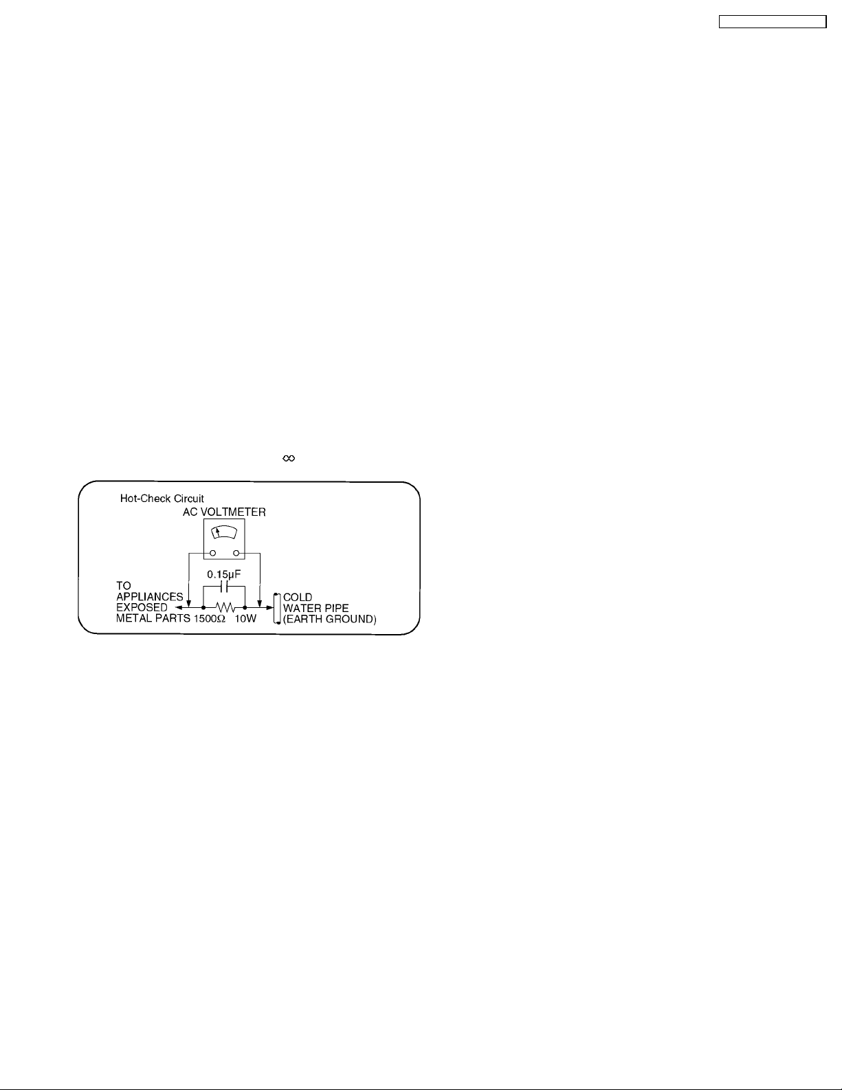
2.1.2. Leakage Current Hot Check (See
Figure 1.)
1. Plug the AC cord directly into the AC outlet. Do not use an
isolation transformer for this check.
2. Connect a 1.5kohm, 10 watts resistor, in parallel with a
0.15µF capacitors, between each exposed metallic part on
the set and a good earth ground such as a water pipe, as
shown in Figure 1.
3. Use an AC voltmeter, with 1000 ohms/volt or more
sensitivity, to measure the potential across the resistor.
4. Check each exposed metallic part, and measure the
voltage at each point.
5. Reverse the ACplugintheACoutlet and repeat eachof the
above measurements.
6. The potential at any point should not exceed 0.75 volts
RMS. A leakage current tester (Simpson Model 229 or
equivalent) may be used to make the hot checks, leakage
current must not exceed 1/2 milliamp. In case a
measurement is outside of the limits specified, there is a
possibility of a shock hazard, and the equipment should be
repaired and rechecked before it is returned to the
customer.
5
Page 6
TC-26LX70L / TC-32LX70L
3 Prevention of Electrostatic Discharge (ESD) to
Electrostatically Sensitive (ES) Devices
Some semiconductor (solid state) devices can be damaged easily by static electricity. Such components commonly are called
Electrostatically Sensitive (ES) Devices. Examples of typical ES devices are integrated circuits and some field-effect transistors and
semiconductor "chip" components. The following techniques should be used to help reduce the incidence of component damage
caused by electrostatic discharge (ESD).
1. Immediately before handling any semiconductor component or semiconductor-equipped assembly, drain off any ESD on your
body by touching a known earth ground. Alternatively, obtain and wear a commercially available discharging ESD wrist strap,
which should be removed for potential shock reasons prior to applying power to the unit under test.
2. After removing an electrical assembly equipped with ES devices, place the assembly on a conductive surface such as
aluminum foil, to prevent electrostatic charge buildup or exposure of the assembly.
3. Use only a grounded-tip soldering iron to solder or unsolder ES devices.
4. Use only an anti-static solder removal device. Some solder removal devices not classified as "anti-static (ESD protected)" can
generate electrical charge sufficient to damage ES devices.
5. Do not use freon-propelled chemicals. These can generate electrical charges sufficient to damage ES devices.
6. Do not remove a replacement ES device from its protective package until immediately before you are ready to install it. (Most
replacement ES devices are packaged with leads electrically shorted together by conductive foam, aluminum foil or comparable
conductive material).
7. Immediately before removing the protective material from the leads of a replacement ES device, touch the protective material
to the chassis or circuit assembly into which the device will be installed.
Caution
Be sure no power is applied to the chassis or circuit, and observe all other safety precautions.
8. Minimize bodily motions when handling unpackaged replacement ESdevices.(Otherwiseham less motion suchasthebrushing
together of your clothes fabric or the lifting of your foot from a carpeted floor can generate static electricity (ESD) sufficient to
damage an ES device).
6
Page 7
TC-26LX70L / TC-32LX70L
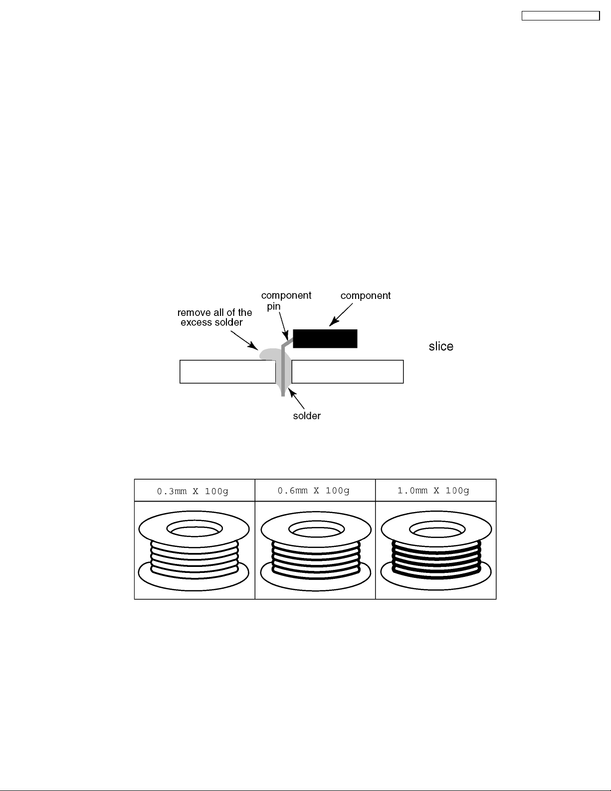
4 About lead free solder (PbF)
Note: Lead is listed as (Pb) in the periodic table of elements.
In the information below, Pb will refer to Lead solder, and PbF will refer to Lead Free Solder.
The Lead Free Solder used in our manufacturing process and discussed below is (Sn+Ag+Cu).
That is Tin (Sn), Silver (Ag) and Copper (Cu) although other types are available.
This model uses Pb Free solder in it’s manufacture due to environmental conservation issues. For service and repair work, we’d
suggest the use of Pb free solder as well, although Pb solder may be used.
PCBs manufactured using lead free solder will have the PbF within a leaf Symbol PbF stamped on the back of PCB.
Caution
· Pb free solder has a higher melting point than standard solder. Typically the melting point is 50 ~ 70 °F (30~40 °C) higher.
Please use a high temperature soldering iron and set it to 700 ± 20 °F (370 ± 10 °C).
· Pb free solder will tend to splash when heated too high (about 1100 °F or 600 °C).
If you must use Pb solder, please completely remove all of the Pb free solder on the pins or solder area before applying Pb
solder. If this is not practical, be sure to heat the Pb free solder until it melts, before applying Pb solder.
· After applying PbF solder to double layered boards, please check the component side for excess solder which may flow onto
the opposite side. (see figure below)
Suggested Pb free solder
There are several kinds of Pb free solder available for purchase. This product uses Sn+Ag+Cu (tin, silver, copper) solder.
However, Sn+Cu (tin, copper), Sn+Zn+Bi (tin, zinc, bismuth) solder can also be used.
7
Page 8
TC-26LX70L / TC-32LX70L
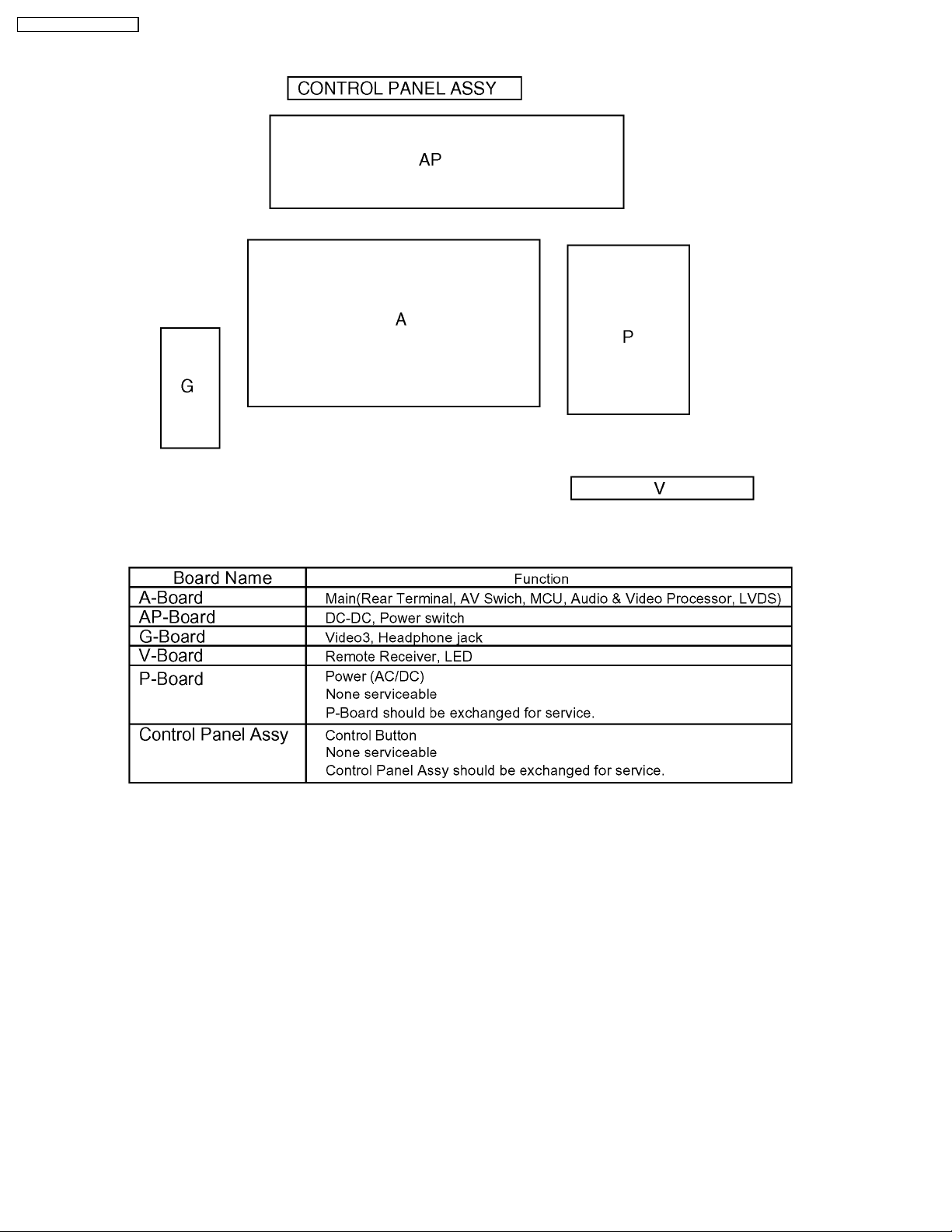
5 Chassis Board Layout
8
Page 9
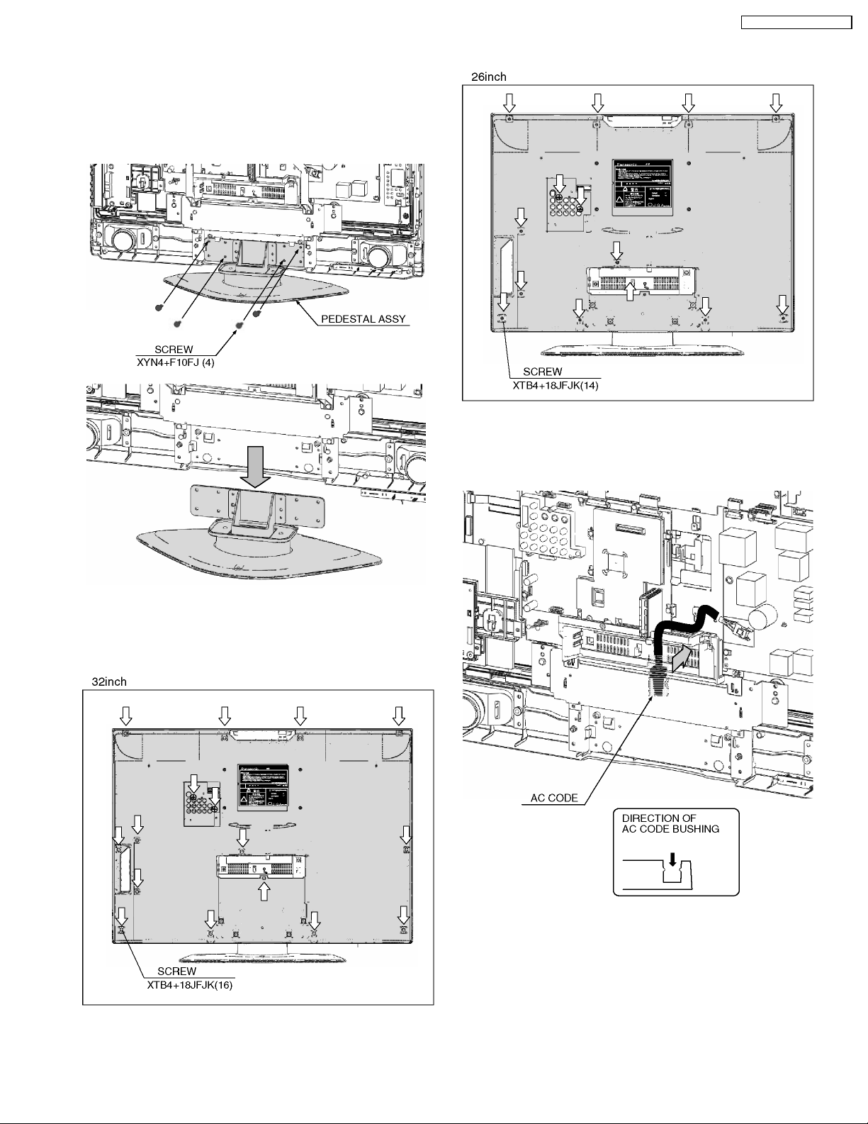
6 Disassembly for Service
6.1. Pedestal assy
1. Lay down the unit so that the rear cover faces upward.
2. Remove the 4 screws.
3. Remove the pedestal assy.
TC-26LX70L / TC-32LX70L
6.3. AC cord
6.2. Rear cover
1. Remove the 16 (32”) / 14 (26”) screws.
2. Remove the rear cover.
1. Remove the bushing of the AC cord from the tuner cover.
2. Disconnect the connector (CN1) of AC cord.
9
Page 10
TC-26LX70L / TC-32LX70L
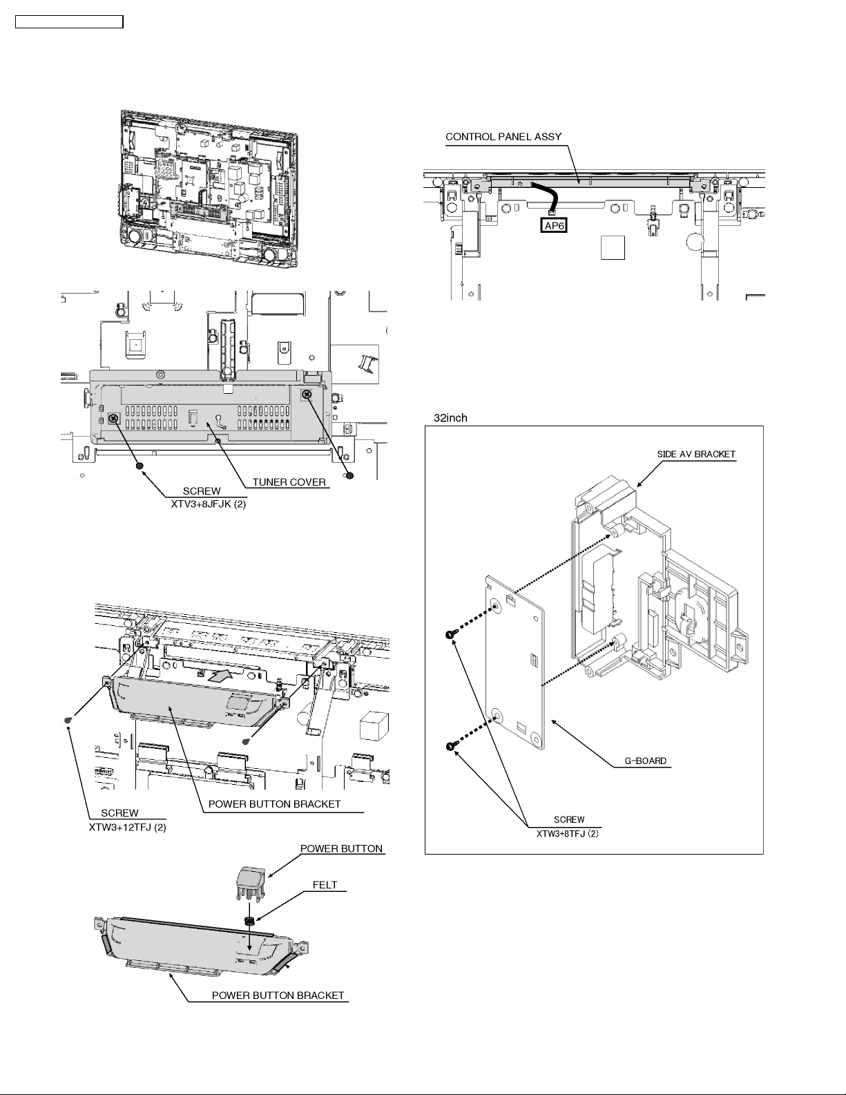
6.4. Tuner cover
1. Remove the 2 screws.
2. Remove the tuner cover.
6.6. Control panel assy
1. Remove the power button bracket. (See section 6.5.)
2. Disconnect the connector (AP6).
3. Remove the control panel assy.
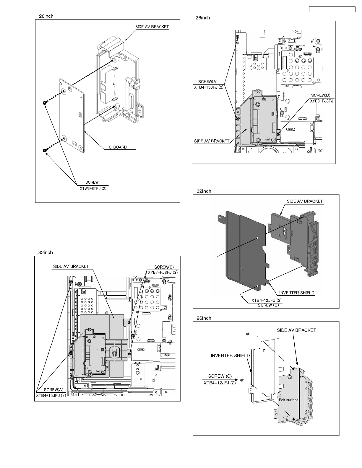
6.7. G-Board
1. Remove the 2 screws.
2. Disconnect the connector (G4).
3. Remove the G-Board.
6.5. Power button bracket
1. Remove the 2 screws.
2. Remove the power button bracket.
10
Page 11
TC-26LX70L / TC-32LX70L
3. Remove the 2 screws (C).
4. Remove the side AV bracket and the inverter shield.
6.8. Side AV bracket and Inverter
shield
1. Remove the screw (A).
2. Remove the screw (B).
11
Page 12
TC-26LX70L / TC-32LX70L
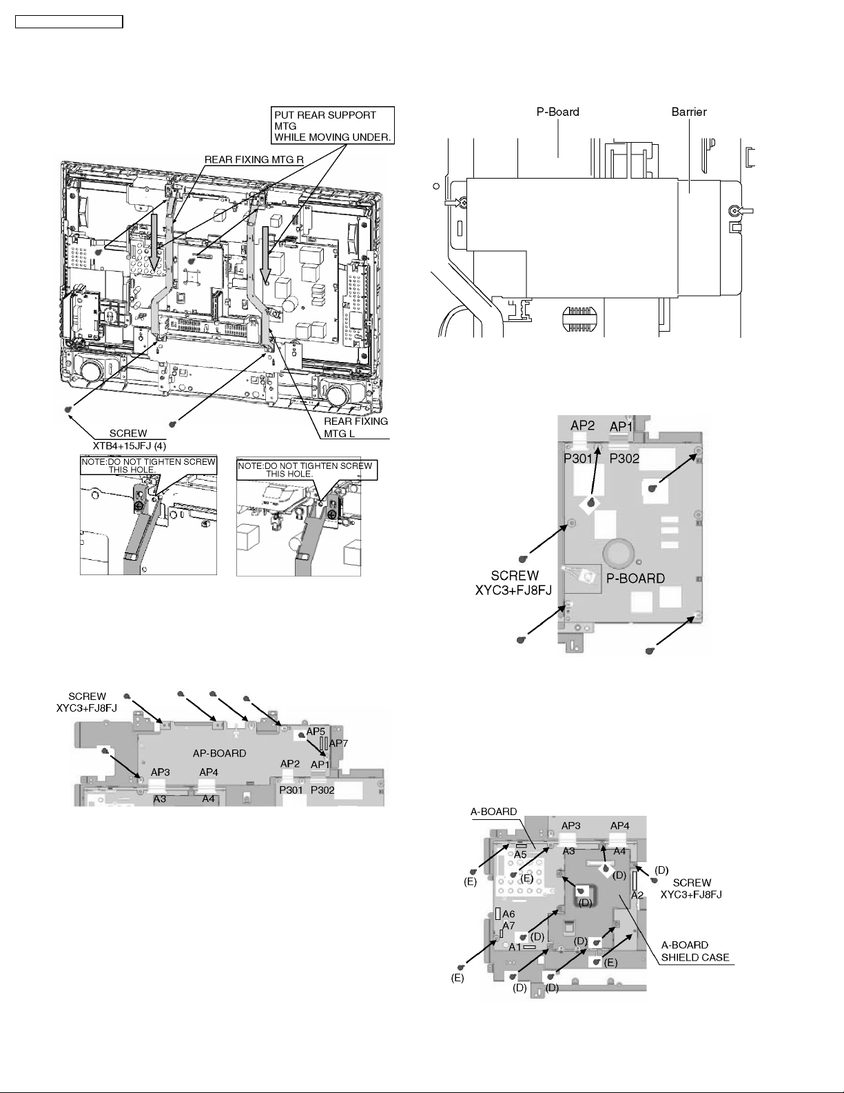
6.9. Rear fixing MTG
1. Remove the 4 screws.
2. Remove the rear fixing MTG.
6.11. P-Board
1. Remove the 2 screws.
2. Remove the Barrier.
3. Disconnect the connectors (P301/P302).
4. Remove the 5 screws.
5. Remove the P-Board.
6.10. AP-Board
1. Remove the 6 screws.
2. Disconnect the connectors (A3/A4/AP5/AP7/P301/P302).
3. Remove the AP-Board.
6.12. A-Board
1. Remove the 7 screws (D).
2. Remove the A-Board shield case.
3. Remove the 4 screws (E).
4. Disconnect the connectors (A1/A2/A3/A4/A5/A6/A7).
5. Remove the A-Board.
12
Page 13
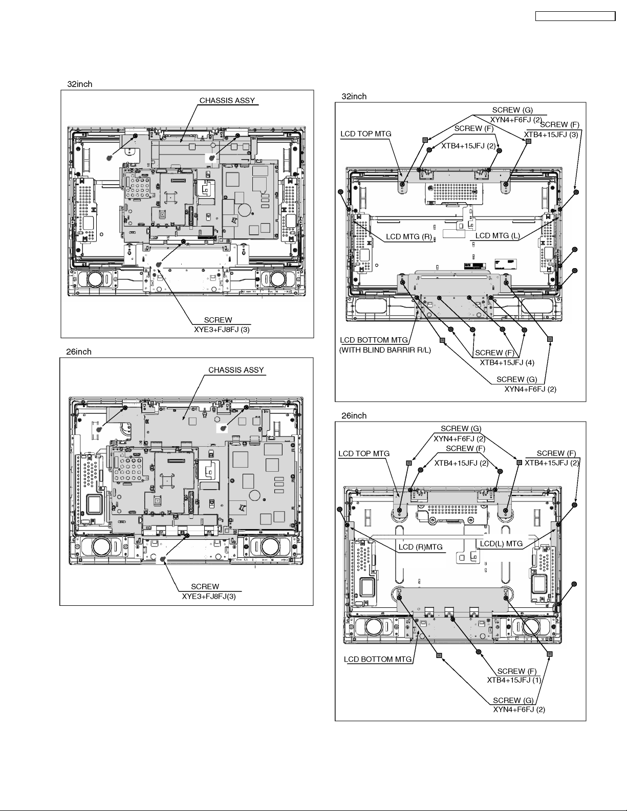
6.13. Chassis assy
1. Remove the 3 screws.
2. Remove the chassis assy.
TC-26LX70L / TC-32LX70L
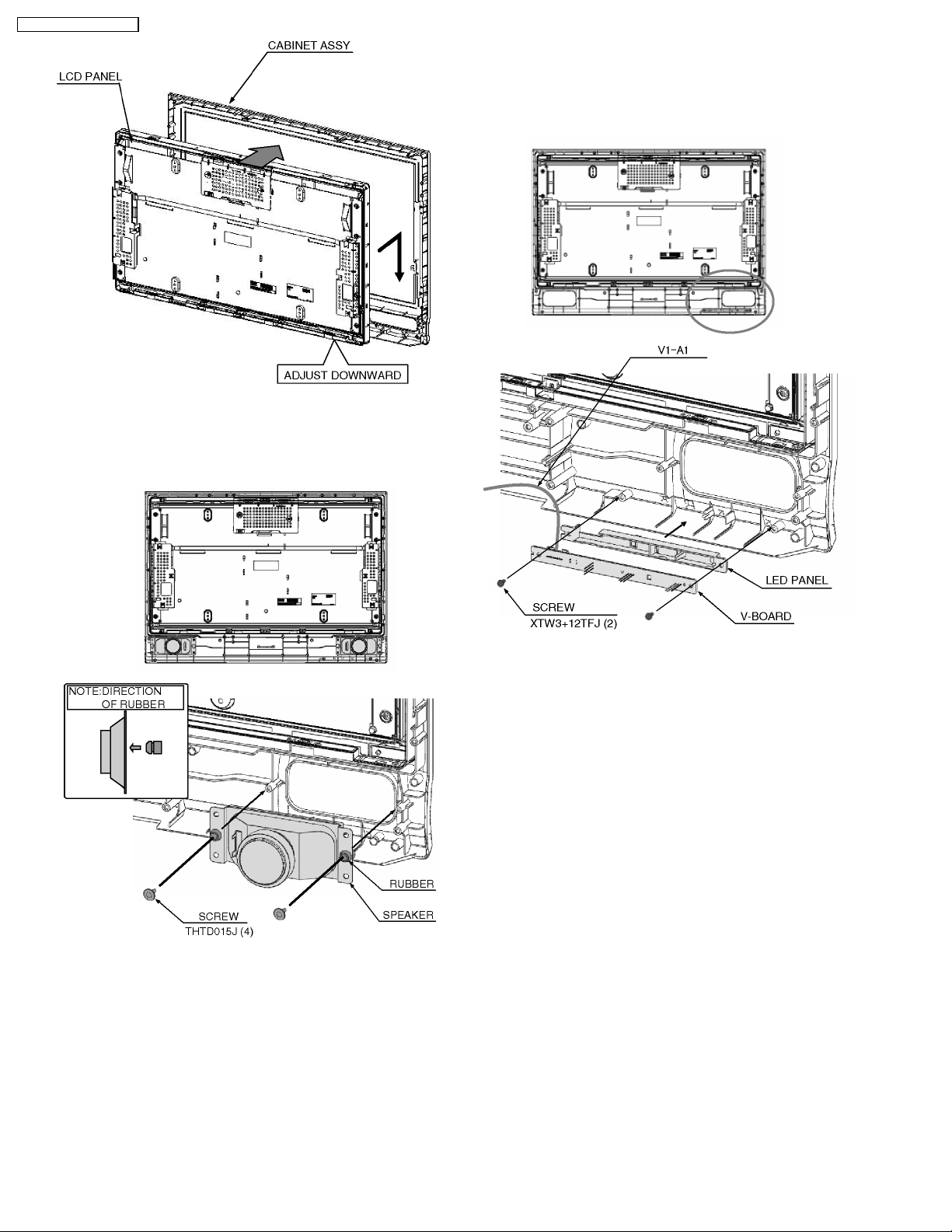
6.14. LCD MTG and LCD panel
1. Remove the 10 (32”) / 6 (26”) screws (F).
2. Remove the 4 (32”) / 4 (26”) screws (G)
3. Remove the LCD MTG.
4. Remove the LCD panel.
13
Page 14
TC-26LX70L / TC-32LX70L
6.15. Speaker
1. Remove the 2 screws.
2. Remove the speaker.
6.16. V-Board
1. Remove the 2 screws.
2. Disconnect the connector (V1).
3. Remove the V-Board.
14
Page 15

7 Caution statement
7.1. Caution statement.
Caution:
Please confirm that all flexible cables are assembled correctly.
Also make sure that they are locked in the connectors.
Verify by giving the flexible cables a very slight pull.
TC-26LX70L / TC-32LX70L
15
Page 16
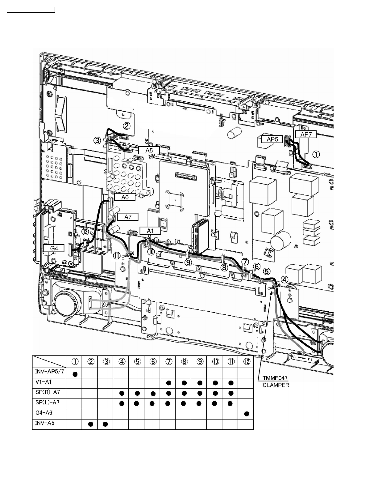
TC-26LX70L / TC-32LX70L
8 Location of Lead Wiring
8.1. Wire dressing (32 inch)
16
Page 17
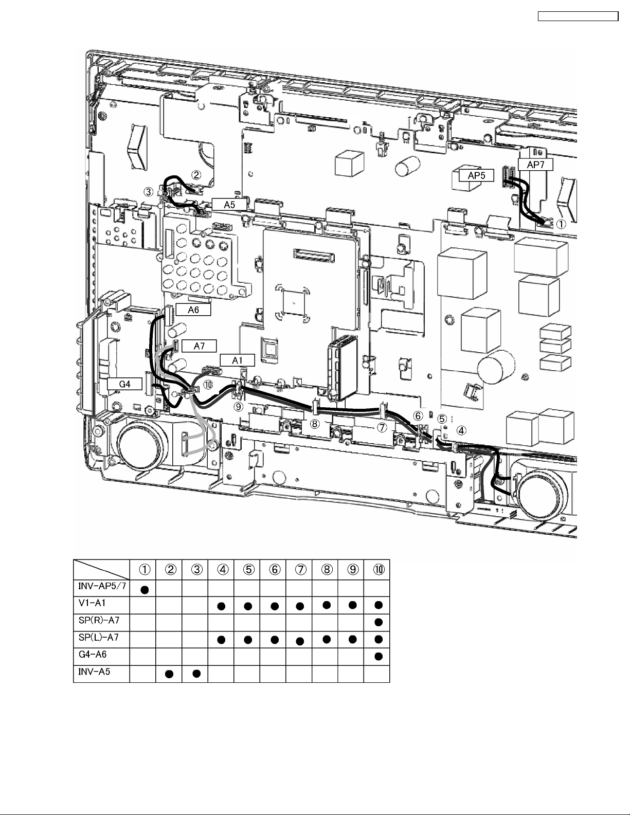
8.2. Wire dressing (26 inch)
TC-26LX70L / TC-32LX70L
17
Page 18

TC-26LX70L / TC-32LX70L
9 EMI Processing
9.1. EMI (32 inch)
18
Page 19

9.2. EMI (26 inch)
TC-26LX70L / TC-32LX70L
19
Page 20

TC-26LX70L / TC-32LX70L
10 Self-check Function
Use the self-check function to test the unit.
1. Checking the IIC bus lines
2. Power LED Blinking timing
10.1. Check of the IIC bus lines
10.1.1. How to access
Produce TV reception screen, and while pressing [VOLUME ( - )] button on the main unit, press [SLEEP] button on the remote
control for more than 3 seconds.
10.1.2. Exit
Press the POWER button twice (off/on) to return to the normal screen.
10.1.3. Screen display
10.1.4. Check Point
Confirm the following parts if NG was displayed.
20
Page 21

TC-26LX70L / TC-32LX70L
10.2. Power LED Blinking timing chart
1. Subject
Information of LED Flashing timing chart.
2. Contents
When an abnormality has occurred the unit, the protection circuit operates and reset to the stand by mode. At this time, the
defective block can be identified by the number of blinks of the Power LED on the front panel of the unit.
10.3. No Power
First check point
There are following 2 states of No Power indication by power LED.
1. No lit
2. Red is lit then turns red blinking a few seconds later. (See 10.2.)
21
Page 22

TC-26LX70L / TC-32LX70L
11 Service Mode
11.1. How to enter into Service Mode
While pressing [VOLUME ( - )] button of the main unit, press [RECALL] button of the remote control three times within 3 seconds.
11.1.1. Key command
“1” button...Main items Selection in forward direction
“2” button...Main items Selection in reverse direction
“3” button...Sub items Selection in forward direction
“4” button...Sub items Selection in reverse direction
“VOL” button...Value of sub items change in forward direction ( + ), in reverse direction ( - )
11.1.2. Contents of adjustment mode
· Value is shown as a hexadecimal number.
· Preset value differs depending on models.
· After entering the adjustment mode, take note of the value in each item before starting adjustment.
11.1.3. How to exit
Switch off the power with the [POWER] button on the main unit or the [POWER] button on the remote control.
22
Page 23

12 Adjustment
12.1. Voltage chart of AP-board
VOLTAGE TEST POINT SPECIFICATION
SUB_5V TP7203 5±0.3V
SUB_9V TP7205 9±0.5V
BT_30V TP7601 31±1.5V
SOUND_18V TP7201 19±0.5V
PANEL_12V TP7702 12±0.5V
TC-26LX70L / TC-32LX70L
23
Page 24

TC-26LX70L / TC-32LX70L
12.2. White balance adjustment
Instrument Name Remarks
1. Remote control
2. LCD WB meter (Minolta CA-110 equivalent)
3. Communication jig
4. Computer for external control
Procedure Remarks
1. Enter the White Balance adjustment mode in Check mode, It checked 300cd/m2 or more that measure
luminance when white.
(Display menu: vivid-basic, LCD-AI: off, backlight: +30)
(If it is 300cd/m2 or less, measures again when cold on after 30 minutes.)
2. It decide “basic color-1” and “basic color-2” when peak adjustment that to measure luminance and the
degree coordinates of color when white.
3. The degree of color is set to a target two other than “basic color-1” (locked 0xff) of R-GAIN, G-GAIN and
B-GAIN, when displayed white. If can not set to the degree of target color, The degree of color is set to a
target two other than “basic color-2” (locked 0xff) of two item.
color temp. - cool
target color (x0,y0) =(0.271±0.002, 0.275±0.002)
color temp. - normal
target color (x0,y0) =(0.285±0.002, 0.293±0.002)
color temp. - warml
target color (x0,y0) =(0.314±0.002, 0.324±0.002)
basic-color1/2
Adjust x-axis B-GAIN R-GAIN R-GAIN
Adjust x-axis B-GAIN R-GAIN R-GAIN
* Point of the degree coordinates of color becomes large when R-GAIN and G-GAIN are enlarged. Point
of the degree coordinates of color becomes small when B-GAIN is enlarged.
* Case of adjust by remote controller, It chooses from the items of R-GAIN,G-GAIN and B-GAIN by [3]
and [4] key on remote controller.
And value is changed by volume [+] and [-] key.
It will be easy to converge if
4. Next, The degree of color is set to a target two other than “basic color : G-CENT” (locked 0x80) of RCENT and CENT when displayed gray.
basic-color
Adjust x-axis
Adjust y-axis
*Case of adjust by remote controller, It chooses from the items of R-CENT, and B-CENT by [3] and [4]
key on remote controller.
And value is changed by volume [+] and [-] key.
5. If It converges on the degree of target color, the data is written to EEPROM.
*Case of adjust by remote controller, Long aggressiveness [8] key on remote controller in the state of R-
CENT,G-CENT and B-CENT
6. Check to the degree coordinates of color when white and gray are in
x=0.271±0.003 y=0.275±0.003 (when color temp is cool)
x=0.285±0.010 y=0.293±0.010 (when color temp is normal)
x=0.314±0.015 y=0.324±0.015 (when color temp is warm)
RED GREEN BLUE
is adjusted preferentially
GREEN The method of adjustment
R-CENT When it is enlarged that point of the degree
coordinates of color becomes large.
B-CENT When it is enlarged that point of the degree
coordinates of color becomes small.
Measurement distance is 21cm
Time to aging is a thing for 20
minutes or more.
The panel is left for three hours
or more in 20-25 °C.
All processes from assembly to
completion are done in a
surrounding environment from
the room temperature 20 °C to
25 °C.
Change to the color temp. by
remote controller or PC. and
Adjustment forthree color.
24
Page 25

12.3. MTS input level adjustment
Instrument Name Connect to Remarks
1. FILTER JIG
2. RMS VOLTAGE METER
3. RF SIGNAL GENERATOR
Procedure Remarks
1. Apply following RF signal at antenna input.
Video : Flat field , 30% modulation
Audio : 300Hz ,100% modulation ,monaural
(70dB±5dB ,75ohmOPEN ,P/S 10dB).
NOTE : Make sure 75us Pre-emphasis is off.
2. Choose MTSIN in MTS adjustment of factory mode.
3. Adjust “MTSIN” data (Input level) until the RMS voltage.
Meter indicates
TP2200-GND or TP1105-GND or TP1107GND
FILTER JIG
RF ANT. INPUT
12.4. MTS stereo separation adjustment
Instrument Name Connect to Remarks
1. OSCILLOSCOPE
2. RF SIGNAL GENERATOR
Procedure Remarks
1. Select stereo mode in the audio menu.
2. Apply following RF signal at antenna Input.
Video : Flat field , 30% modulation.
Audio : 300Hz ,30% modulation ,stereo (Left only)
(70dB±5dB ,75ohmOPEN ,P/S 10dB)
Note : After setting 30% modulation with P.L. SW
And N.R. SW off , turn P.L. SW and N.R. SW ON.
3. Choose SEPAL in MTS adjustment of factory mode.
4. Adjust “SEPAL” data (Low-level separation) until the amplitude of the waveform on the oscilloscope is
MINIMUM.
5. Apply following RF signal at antenna Input.
Video : Flat field , 30% modulation
Audio : 3kHz ,30% modulation ,stereo (Left only)
(70dB±5dB ,75ohmOPEN ,P/S 10dB)
Note : After setting 30% modulation with P.L.. SW
And N.R. SW off , turn P.L. SW and N.R. SW ON.
6. Choose SEPAH in MTS adjustment of factory mode.
7. Adjust “SEPAH” data (High-level separation) until the amplitude of the waveform on the oscilloscope is
MINIMUM.
8. Repeat step 2. to 7. Until Low-level separation and High-level separation satisfy above-mentioned
conditions.
TP1104-GND or TP1106-GNDor Monitor out RGND
RF ANT. INPUT
The separation must be more
than 20 dB at 300Hz and
3kHz..
More than 18dB when
measures at monitorOut.
TC-26LX70L / TC-32LX70L
25
Page 26

TC-26LX70L / TC-32LX70L
13 Hotel mode
1. Purpose
Restrict a function for hotels.
2. Access command to the Hotel mode setup menu
In order to display the Hotel mode setup menu, please enter
the following command (within 2 second).
[TV] : Vol. “Down” + [REMOTE] : TV/VIDEO (3 times)
Then, the Hotel mode setup menu is displayed.
3. To exit the Hotel mode setup menu
Select the “mode” in the hotel mode setting menu is mode
“off”, and switch off the power with the [POWER] button on
the main unit or the [POWER] button on the remote control.
4. Explain the Hotel mode setup menu
item Function
Mode Select hotel mode ON/OFF
Input Select input signal modes.
Channel Select channel when input signal is RF.
Volume Adjust the volume when each time power is
Vol. Max Adjust maximum volume.
OSD Ctrl Restrict the OSD.
FP Ctrl Select front key conditions.
Pow Ctrl Select POWER-ON/OFF condition when AC
Set the input, when each time power is
switched on.
Selection:
-/RF/COMP/HDMI1/VIDEO1/
VIDEO2/VIDEO3
· Off: give priority to a last memory.
Set the channel, each time power isswitched
on.
Selection:
Any channel number or “-”.
“-” means the channel when turns off.
switched on.
Range:
0to63
Range:
0to63
Selection:
OFF/PATTERN1
· OFF: No restriction
· PATTERN1: restriction
Selection:
Off/Pattern1/All
· Off: altogether valid.
· Pattern: only input key is valid.
· All: altogether invalid.
power cord is disconnected and then
connected.
OFF: The same condition when AC power
cord is disconnected.
ON: Forced power ON condition.
26
Page 27

14 Conductor View s
14.1. AP-Board
6
5
4
Parts Location
IC
IC7203 D-2
IC7205 H-2
IC7209 F-3
IC7210 F-2
IC7212 C-2
IC7215 C-2
IC7218 E-2
TP
TP7151 E-1
TP7200 E-2
TP7201 E-2
TP7202 G-2
TP7203 H-2
TP7204 F-2
TP7205 F-2
TP7206 E-2
TP7207 G-3
TP7402 F-2
TP7451 G-2
TP7502 H-2
TP7601 G-1
TP7701 B-2
TP7702 B-2
TP7801 C-2
TP7802 C-2
TP7901 H-3
TP7902 F-3
TP7903 H-3
TP7904 C-2
TP7905 C-2
AP-BOARD (FOIL SIDE)
TRANSISTOR
Q7204 C-3
Q7205 C-3
Q7206 C-3
Q7207 C-3
Q7208 B-3
Q7209 B-3
Q7210 G-3
Q7211 G-3
Q7212 C-3
Q7213 B-3
Q7214 B-3
Q7221 D-2
Q7222 D-2
Q7223 C-3
Q7224 C-3
Q7301 E-3
Q7303 G-2
Q7450 F-3
Q7451 F-3
Q7452 D-2
Q7503 H-2
Q7504 H-2
Q7506 H-2
Q7508 B-3
Q7701 B-2
Q7702 B-3
Q7804 D-2
Q7805 E-2
Q7806 E-2
Q7901 H-2
Q7902 H-2
TC-26LX70L / TC-32LX70L
AP
AP-BOARD (FOIL SIDE)
TNPA3849AHS
3
2
1
TH-26/32LX70L
AP-BOARD TNPA3849AHS
ABCDEFGH I
TH-26/32LX70L
AP-BOARD TNPA3849AHS
27
Page 28

TC-26LX70L / TC-32LX70L
6
5
Parts Location
AP-BOARD
(COMPONENT SIDE)
IC
IC7203 E-2
IC7205 B-2
IC7209 D-2
IC7210 C-2
IC7212 G-2
IC7215 F-2
IC7218 E-2
AP
4
AP-BOARD (COMPONENT SIDE)
TNPA3849AHS
3
2
1
TH-26/32LX70L
AP-BOARD TNPA3849AHS
ABCDEFGH I
TH-26/32LX70L
AP-BOARD TNPA3849AHS
28
Page 29

14.2. A-Board
TC-26LX70L / TC-32LX70L
A-BOARD (FOIL SIDE)
TNPH0677AGS (TC-26LX70L), TNPH0677ABS (TC-32LX70L)
6
5
4
R3051
C2176
R3128
D3022
D3021
3
R3129
R3001
IC2007
C2166
R2146
R2145
C2107
C2108
C4814
C4815
R4818
2
R3015
R3123
R4819
C2177
FL3048
R3121
R3013
1
C2130
L2001
A7
C2310
Q2307
C2104
C2105
Q2308
C2314
R3052
R3053
FL3052
D3032
D3031
FL3050
R3130
R3002
C2370
R2147
L2004
C2167
R2144
JS2017
R3122
C2140
L2002
C2131
R2319
R2320
R2323
R2321
C2369
R3126
D3020
D3019 TP077
D3015
D3029
D3030
R3125
R3017
D3018
R3014
R3124
D3017
D3016
FL3049
D3028
R3127
R3016
JS2011
C2162
R2109
D2001
C2115
R2155
C2116
C2117
C2163
R2156
C2118
C2120
D3013
D3014
R3119
D3027
FL3037
R3120
R3118
R3011
R3012
C2165
JK3002
C2164
D3011
R3115
R3009
FL1803
FL1802
FL1804
JS1807
JS1809
JS1808
C1860
C1861
C1862
TP050
TP053
TP049
FL3035
TP051
R2098
C2112
R2111
JS2012
R2308
D2301
D2305
D2304
R3117
R3111
D3009
D3026
FL3036
R3116
C2156
C2159
JS1810
C1863
FL3034
R3010
R3110
R3007
C2123
C2161
C2121
C2148
C2149
C2150
C2151
C2152
C2153
C2154
C2155
FL1805
TP052
R2132
R2118
R2119
R2123
R2124
R2125
R2126
R2127
R2128
R2129
R2130
R2133
R2134
R3113
D3010
R3114
R3008
C3063
D1819
R1829
C1858
D1820
R1831
R1832
Q1805
R1830
TP2008
TP2009
R4322
R4239
C4136
C4135
C4116
R4231
C4117
R4320
R4237
C4132
C3068
C4131
R3029
R3019
R3104
FL3030
R3103
R3022
D3001
D3007
D3008
R3109
D3003
TP4061
R1176
R1826
FL3033
R3005
C2174
R2135
R2136
R2143
R2150
R2151
R1824
D3024
R3137
C2171
R3135
C3078
R2138
R2141
C3079
R2137
R2142
C3135
R3138
C3081
C2170
R2148
R3136
R2149
C2371
D3012
D3006
D3004
D3005
R1175
R1174
TP1075
TP1076
Q1803
R1827
TP1078
C4144
R1825
R1823
D3025
R3108
R3112
R3006
C2160
R2131
IC2006
TP1077
C1857
TP1074
TP1079
R1177
Q1804
R1828
D1812
R1833
Q1806
R1834
R1835
R3031
C3069
L3001
L3002
R3024
C3070
C3071
C3072
D3023
D3002
FL3031
R3100
R3043
R3034
R3035
R3036
R3101
R3102
R3131
C3073
Q3008
R3133
Q3009
R3134
Q3005
C3080
C2168
R3105
FL3032
R3106
R3107
Q3006
C3076
C3075
C3074
R3132
Q2032
Q2031
C4143
C2169
C3062
R3003
R3004
R4817
R4816
C4813
C4812
D5024
R5103
R5104
D5026
C5061
R3037
R3038
R3041
R3039
R3042
Q3007
C3077
R3040
R1238
TP1202
R1232
TP1203
R1235
TP1205
R1231
R1230
TP1206
TP1207
R1228
R1229
TP1208
R5026
TP5002
TP5004
D5014
D5017
Q5008
R5052
R5120
R5048
TP5009
L5012
Q1216
FL5004
R5118
C2372
Q1215
TP1824
R5121
C5015
C5014
TP5011
C5013
IC5003
C5021
R5057
R5117
FL5006
R5053
R5123
Q5009
R5049
R5122
R5072
R5074
R5071
C5039
R5076
C5037
C5035
TP5008
C4127
C4130
R4236
R4319
C4123
TP1021
C4124
R4234
C1828
TP1822
C1829
TP1818
R1233
R1234
L1806
C1833
R5127
R5045
R5044
L5005
L5006
R5041
R5040
R5036
C5016
C5017
D5022
R5033
R5027
C5044
C5043
C5045
R5029
R5124
R5110
R5112
R5113
R5107
C4070
C4069
C4073
R1189
R1188
R4149
D4001
R4150
C4137
C1905
R021
R020
C021
C020
D3865
R3865
D3867
R3878
R3867
JS1804
D3864
JS1803
JS1806
C1827
JS1805
TP1819
R5023
JK5001JK5002
TP5003
TP5001
IC5002
C5012
R5031
TP5010
R5028
R5032
Q5003
C5047
C5046
C5058
C4110
C4043
Q1153
C4040
JS4074
R1845
R1844
TP1828
C1887
C1892
R1849
TP1820
TP1024
C1826
R4249
TP1817
Q5004
IC4002
R1837
R1836
C4805
R5034
C4062
R4250
C4052
JS4082
R4802
R4805
R1847
R5126
TP5005
TP5006
R5030
C5020
C5056
R5058
C5029
C5032
L5010
C5036
C5060
C5048
R5109
R5108
D4122
C4061
R4265
TP1176
C4053
C4051
C4109
C4044
C4041
C4038
C4039
JS4075
R4062
R4064
R4748
R4747
R4763
R4764
R4801
C4804
R4804
R1848
C1879
C1886
IC1807
R1143
R3874
D3869
C1864
D5011
D5015
L5003
C5007
L5004
R5125
R5042
R5038
C5008
R5039
R5035
R5043
C5011
R5088
CL5001
C4803
IC5001
C5057
R4010
R4744
R4761
C4801
R1851
R3860
R5132
Q5025
Q5022
R4264
R4112
R4007
R4191
R4263
R4199
R4252
R4253
C4028
R4276
R4279
C4149
C4006
C4007
C4114
C4008
R4746
R4762
L4801
C4802
C1885
C1884
C1883
C4138
D3863
D3860
D3861
R3877
D3868
R3873
C4001
C4026
R4271
R4274
R4277
C4013
R4813
R4809
C4012
C4016
C4010
C4011
C4005
C4014
R4812
R4811
C5059
C4141
C2373
C1904
TP1825
D3866
R3866
Q3862
R3864
R3879
R3876
C4126
C4125
R4235
C026
TP1108
C2211
C2212
C2213
C2201
C2214
C2215
C2216
C2217
R1194
R1195
R1173
R1167
Q1149
R4008
R4014
TP1101
D1101
R4075
R4073R4066
R4225
R4060
R4221
R4243
R4242
R4241
R4240
CL4018
CL4019
CL4016
R4069
R4227
CL4017
R4232
R4081
R4059
R4256
R4058
R4072
R4078
C4002
R4071
JS4047
JS4045
JS4073
JS4072
JS4044
Q1807
C1903
Q1808
R1861
R1862
R3880
C3860
Q3861
R3863
D3862
R1159
R4074
IC1101
R1158
R1162
C1167
R1160
R1163
R1164
Q1148
Q1147
R4667
R1168
R1165
JS4038
JS4048
JS4041
JS4039
JS4046
C1902
R1879
A12
CL4554
TP1201
TP4008
D3870
Q3860
R3875
R3861
R3862
R2220
IC2202
C2219
C2218
TP8
TP6
TP4
TP2
TP0
TP1
TP056
R4122
R4318
R4666
TP055
TP086
R4317
C4171
C4172
C2374
R4655
D4123
D1802
TP1812
R1868
R1869
C1894R1853
Q1809
R1870
TP1036
TP2200
C003
C002
TU001
L001
R2212
R2211
R2210
R2209
TP1107
C2222
C2221
TP1106
C2220
R2208
JS2018
C2205
JS2019
C2206
TP9
TP7
TP5
TP3
R4143
C4170
TP079
R4139
C4167
R4193
R4138
C4168
C4169
R4145
R4228
TP054
R4097
R4099
TP1811
TP1809
C1907
C1893
R1871
R1865
R4102
R4103
IC4003
R1867
R1866
TP1810
TP1807
C4181
C4178
TP078
TP081
C4179
C4180
TP074
TP075
TP076
R4144
TP071
TP073
TP072
TP069
TP070
TP066
TP067
TP063
TP064
R4089
R4100
R4094
TP084
R4101
R4216
C4112
L4015
R4137
C4129
R1852
R1850
C1837
R1811
R1863
D1803
D1801
D1824
D2006
TP1806
TP1040
TP1042
TP1808
TP1814
TP1710
TP068
TP065
TP062
C4079
TP082
R4189
R4203
C4155
C4154
C4147
R4268
R4269
R4134
R1815
L1805
TP1204
TP1709
TP1708
TP1707
TP1706
TP1705
C4081
TP1704
TP1703
TP1702
TP1701
R4226
R4233
D1808
C1877
R1840
IC1806
C1869
D1811
C1834
D1810
TP1805
C1821
C1822
TP1813
TP1713
TP1712
C4128
C4121
C4122
C4807
L4904
C4808
C1876
R1872
C1878
TP1826
R1843
R1839
R1838
C1873
R1841
R1842
C1865
C1872
C1871
C1870
C1836
C1835
R1814
C1838
R1813
IC1803
R1812
R1184
C1181
R1178
R1179
R1185
R1181
Q1151
R1183
R1180
C024
C025
R024
R025
C4809
R1702
R1701
R1700
TP1711
R1817
C1839
R1816
C1840
Q1801
R1818
Q1802
C1841
R1873
D1823
R1858
R1857
R1856
TH-26LX70L
A-BOARD TNPH0677AGS
ABCDEFGH I
TH-32LX70L
A-BOARD TNPH0677ABS
29
TH-26LX70L
A-BOARD TNPH0677AGS
TH-32LX70L
A-BOARD TNPH0677ABS
Page 30

TC-26LX70L / TC-32LX70L
A
Parts Location
IC
IC1101 G-2
IC1803 H-1
IC1806 H-2
IC1807 E-1
IC2006 C-2
IC2007 B-3
IC2202 G-5
IC4002 E-4
IC4003 G-2
IC5001 F-5
IC5002 E-6
IC5003 E-6
TRANSISTOR
Q1147 G-2
Q1148 G-2
Q1149 G-4
Q1151 H-1
Q1153 E-3
Q1215 E-2
Q1216 E-2
Q1801 H-1
Q1802 H-1
Q1803 D-1
Q1804 C-1
Q1805 C-1
Q1806 D-1
Q1807 F-1
Q1808 F-1
Q1809 G-1
Q2031 D-2
Q2032 D-2
Q2307 B-4
Q2308 B-4
Q3005 D-2
Q3006 D-3
Q3007 D-3
Q3008 D-3
Q3009 D-3
Q3860 F-1
Q3861 F-1
Q3862 F-1
Q5003 E-5
Q5004 E-5
Q5008 E-6
Q5009 E-5
Q5022 F-5
Q5025 F-5
A-BOARD (FOIL SIDE)
TP
TP0 G-4
TP1 G-4
TP2 G-4
TP3 G-4
TP4 G-4
TP5 G-4
TP6 G-4
TP7 G-4
TP8 G-4
TP9 G-4
TP049 C-1
TP050 C-1
TP051 C-1
TP052 C-1
TP053 C-1
TP054 G-3
TP055 G-3
TP056 G-3
TP062 H-3
TP063 H-3
TP064 H-3
TP065 H-3
TP066 H-3
TP067 H-3
TP068 H-3
TP069 H-3
TP070 H-3
TP071 H-3
TP072 H-3
TP073 H-3
TP074 H-3
TP075 H-3
TP076 H-3
TP077 H-3
TP078 H-3
TP079 H-3
TP081 H-3
TP082 H-3
TP084 H-3
TP086 G-3
TP1021 E-1
TP1024 E-1
TP1036 G-1
TP1040 H-1
TP1042 H-1
TP1074 C-1
TP1075 C-1
TP1076 D-1
TP1077 C-1
TP1078 D-1
TP1079 C-1
TP1101 F-4
TP1106 H-4
TP1107 H-5
TP1108 G-5
TP1176 F-4
TP1201 G-2
TP1202 D-2
TP1203 D-2
TP1204 H-1
TP1205 D-2
TP1206 D-2
TP1207 D-2
TP1208 D-2
TP1701 H-3
TP1702 H-3
TP1703 H-3
TP1704 H-3
TP1705 H-3
TP1706 H-3
TP1707 H-3
TP1708 H-3
TP1709 H-3
TP1710 H-3
TP1711 H-2
TP1712 H-3
TP1713 H-3
TP1805 H-1
TP1806 G-1
TP1807 G-1
TP1808 G-1
TP1809 G-2
TP1810 G-1
TP1811 G-2
TP1812 G-1
TP1813 H-1
TP1814 H-1
TP1817 E-1
TP1818 E-1
TP1819 E-1
TP1820 E-1
TP1822 E-1
TP1824 E-1
TP1825 F-1
TP1826 H-2
TP1828 E-1
TP2008 C-6
TP2009 C-5
TP2200 H-6
TP4008 G-2
TP4061 C-1
TP5001 F-6
TP5002 E-6
TP5003 F-6
TP5004 E-6
TP5005 F-6
TP5006 F-6
TP5008 E-5
TP5009 D-6
TP5010 E-6
TP5011 E-6
Parts Location
IC
IC1102 C-4
IC1804 B-4
IC1805 C-4
IC1808 B-1
IC2001 G-6
IC2005 H-4
IC4001 D-4
IC4004 B-3
IC4005 B-2
IC4801 D-2
IC5004 E-5
IC5005 F-5
A-BOARD (COMPONENT SIDE)
TRANSISTOR
Q001 B-4
Q1141 D-2
Q1142 D-2
Q1143 D-2
Q1144 D-1
Q1145 D-2
Q1146 C-2
Q1150 C-3
Q1152 C-5
Q1810 C-1
Q1811 D-1
Q2019 G-4
Q2020 G-5
Q2030 G-4
Q2303 F-5
Q2305 G-5
Q2306 G-5
Q2312 G-5
Q2313 G-5
Q3001 F-4
Q3002 F-4
Q3003 F-4
Q3004 F-4
Q4001 E-3
Q4002 B-2
Q4003 B-2
Q4120 C-3
Q4121 C-2
Q4801 D-2
Q5001 E-6
Q5002 F-2
Q5018 D-6
Q5019 D-6
Q5020 D-6
Q5021 D-6
Q5023 F-5
Q5024 D-5
TP
TP1104 B-4
TP1105 C-5
TP1815 A-1
TP1816 E-1
TP1821 E-1
TP1823 E-1
TP1829 A-1
TP1830 E-1
TP1831 F-1
TP1832 A-2
TC-26/32LX70L
A-BOARD PARTS LOCATION
TC-26/32LX70L
A-BOARD PARTS LOCATION
30
Page 31

A-BOARD (COMPONENT SIDE)
TNPH0677AGS (TC-26LX70L) , TNPH0677ABS (TC-32LX70L)
TC-26LX70L / TC-32LX70L
ZA4006
6
C014
TU001
5
A8
4
A14
ZA4008
R4127
R4208
R4126
FL4003
ZA4030
FL4002
FL4001
R4125
R4207
R4123
R4117
R4206
R4115
R4113
R4205
R4111
R4109
R4204
R4107
R4815
C4150
C4139
R4814
C4811
C4810
C1875
3
A2
2
D1813
L1811
TP1832
C4140
C022
C023
C1899
C1898
R022
IC1808
R1859
R023
C1897
C1901
C1900
D1822
R1860
D1821
TP1815
1
TP1829
C1867
C1868
C1866
TP2200
C003
C002
C004
L001
ZA4007
C015
R010
R009
C016
R001
C008
TP1105
JS004
JS003
C011
C009
C010
R005
JS002
R003
R004
Q001
TP1104
C1844
IC1804
C1842
R1820
R1819
C1846
C4074
C4087
C4084
R4087
C4151
Q4003
C4115
Q4002
R4090
ZA4001
L4012
C4102
R4146
R4142
C4101
R4192
R4224
C4166
C4092
C4091
IC4004
R4104
C4077
C4076
R4118
R4114
C4152
R4129
C4103
C4153
R4215
C4156
R4135
C4086
IC4005
C4146
R4132
R4131
C1874
D1815
C1824
C1823
L1810
L1809
JS1802
JS1801
A4
C1843
C1845
C1853
C1852
C1847
R1822
C1848
C1850
L4010
R4098
R4196
R4194
R4198
C4093
R4210
R4083
R4209
C4078
C4157
R4124
C4100
C4118
R4140
C4096
R4141
C4098
R4136
R4188
L4021
R1880
R4650
JS4081
C1851
C1849
IC1805
R1821
L4011
C4095
C4094
C4075
C4089
R4200
R4202
C4099
C4097
C4090
C4165
C4164
C4088
R4133
R4222
R4218
R4130
R4128
C4083
C4085
R4121
R4120
R4119
R4229
C4082
C4080
C4161
R4217
R4201
R4092
C4159
R4116
R4281
D4121
Q4120
R4084R4093
R4110
R4108
R4105
R4643
C4173
JS4080
C1825
R4219
R4282
R4106
Q4121
C4158
R4640
R4639
FL4021
CL4529
R4657
R4654
R4820
R4821
R4644
Q1152
R1186
R1187
IC1102
R4324
R4079
R4323
C4105
R4077
R4080
C4104
L4009
C4068
R4244
L4007
C4057
R4759
R4758
R4757
R4756
R4754
R4755
R4753
R4752
R4750
R4751
C4022
L4006
R4038
C4035
CL4022
CL4023
CL4020
C4034
CL4021
C4009
R4223
C4163
L4001
R4230
R4214
C4162
C4160
R4267
Q1150
R1166
R1169
R1170
R1161
Q1146
R1157
CL4656
CL4530
CL4533
A12
R4659
R4652
R4658
R4663
R4662
R4665
R4664
R4656
C4817
C4816
Q1810
R1874
R1875
R4248
R4247
R4246
R4245
C4059
C4054
C4050
C4049
C4045
C4042
JS4049
CL4580
R5095
R5093
D5023
Q5018
C5055
R5099
R5101
R5097
R5098
C5054
Q5020
Q5021
R5100
Q5024
R5131
R1190
R1192
C1169
C1168
R4212
R1171
R4211
R1172
R4011
R4259
R4257
R4260
R4258
R4255
R4254
CL4015
CL4024
C4029
CL4014
C1177
C4032
R4012
R4003
C4019
L4002
R4001
R1156
R1155R4220
Q1145
R4760
C4174
L4022
JS4050
JS4077
JS4076
Q1811
C1906
R1877
R1878
R1876
D1825
Q5019
C5053
R5096
R5102
R5094
R5130
C4176
R4261
R4262
C4177
C4067
C4024
C4021
C4148
L4003
L4023
JS4078
C4119
C4183
C4025
ZA4002
R1147
C4066
R4810
JS4079
C5030
C5034
R5091
X4001
C4071
C4072
C4182
R4082
C4064
R4325
R4326
C4065
IC4001
C4027
R4273
R4272
R4278
R4275
C4003
C4004
C4015
C4017
R4808
Q4801
C4806
R4807
C4175
L1812
R1145
R1146
Q1144
Q1143
Q1141
R1142
JK5001
C5005
C5001
R5024
Q5001
R5005
R5010
R5014
R5013
R5012
R5011
D5019
D5007
D5005
D5016
D5012
D5009
C5009
D5021
C5019
D5025
D5027
R5105
R5106
C5022
R5063
R5065
R5067
R5069
R5073
C5038
X5001
L5007
R5079
R5078
R5080
R5077
L4014
L4016
C4111
R4266
C4030
C4031
R4009
C4020
L4005
C4023
R4280
L4004
C4018
IC4801
C1880
C1882
R1144
C1141
R1148
R1149
Q1142
R5003
R5008
R5009
R5007
FL5002
C5003
R5001
D5001
D5003
R5075
R5081
R5082
C4120
C4060
R4251
C4058
C4056
C4046
C4037
C4036
R4190
R4213
R4004
R4021
D1816
L1813
C1881
D1818
C5010
IC5004
R5085
R5086
C4145
R4148
R4065
R4063
R4061
R4147
R4057
R4055
R4053
C4055
R4049
R4047
C4106
R4034
R4031
R4028
R4025
R4803
D4801
R4806
R5087
R5084
C4113
L4008
R4050
R4048
R4197
R4195
R4042
R4044
R4040
R4039
C4033
R4032
R4015
R4029
Q4001
R4005
R4026
R4018
R4023
D1809
C1890
C1891
R1846
C1889
C1888
A3
JK5002
R5018
R5020
R5022
R5017
R5019
R5021
D5008
D5006
D5020
D5018
D5004
D5010
D5013
L5008
R5116
FL5005
C5018
C5027
C5025
C5026
C5028
C5031
C5033
C5040
C5041
C5042
R5083
R5111
ZA4004
ZA4003
TP1821
TP1830
C5002
R5016
R5015
R5004
R5002
FL5001
C5004
D5002
Q5002
R5006
C5006
R5115
R5060
L5013
L5009
R5061
R5062
R5064
R5066
R5068
C5024
R5070
L5011
FL5003
R5114
C1830
R5025
C5023
R5129
R5128
R5054
Q5023
R5055
C5050
IC5005
C5051
JS3083
JS3082
JS3081
JS3080
JS3079
JS3078
JS3077
TP1823
TP1831
C1831
C1832
TP1816
ZA4005
C5049
FL5007
R5119
C4142
R1236
R1237
A15
R1239
R4321
R4238
C4134
C4133
L2003
C2175
C2223
C2139
R2383
JS2301
R2381
D2309
D2005
Q2303
R2303
R2304
C2367
R3020
R3032
R3033
Q3004
R3027
C3065
S3003
R1864
R3021
R3028
R3030
Q3001
C3067
Q3003
R3026
R3025
Q3002
R3023
S3005
S3004
S3007
D1102
R1193
C1896
R1854
C1895
A16
C1854
JS2023
A1
C1180
C1143
C2102
R2103
R2107
R2159
R2160
C2375
Q2313
R2307
C3064
C2132
R2104
C2103
C2101
L2005
R2115
R2114
R2139
C2113
C2173
C2110
R2140
C2111
C2106
R2105
C2133
R2108
R2106
C2109
JS2014
R2309
Q2312
R2310
R2313
R2382
R2306
Q2305
Q2306
R2314
R2110
Q2030
D2004
Q2019
JS2306
C2368
S3010
S3009
S3011
S3008
S3006
L1808
C1856
L1807
C1855
JS2013
C1178
C1179
IC2001
R2161
AP
R2121
C2068
R2097
R2096
R2112
R2152
A21
S3015
S3017
JK3002
S3012
C1859
A5
JS2005
L2001
C2125
R2099
C2114
C2122
C2178
C2124
C2179
R2100
C2119
C2138
C2142
Q2020
R2122
R2120
C2144
C2146
IC2005
C2147
C2145
R2113
R2117
S3016
S3014
S3013
JS2022
JS2015
R2116
R2101
C2126
C2180
C2140
C2181
C2128
R2102
L2002
C2157
C2141
C2172
C2158
S3021
S3022
S3020
S3019
S3018
JS2004
C2130
D2002
C2127
C2134
C2135
A7
C2136
C2137
C2129
D2003
JS2016
C2131
R2153
R2154
C2143
JS2021
C2100
A6
JS2020
S3002
S3001
TH-26LX70L
A-BOARD TNPH0677AGS
ABCDEFGH I
TH-32LX70L
A-BOARD TNPH0677ABS
31
TH-26LX70L
A-BOARD TNPH0677AGS
TH-32LX70L
A-BOARD TNPH0677ABS
Page 32

TC-26LX70L / TC-32LX70L
14.3. G and V-Board
6
V-BOARD (FOIL SIDE)
TNPA4325S
5
G V
V-BOARD (COMPONENT SIDE)
TNPA4325S
4
3
2
G-BOARD (FOIL SIDE)
TNPA4266S
G-BOARD (COMPONENT SIDE)
TNPA4266S
1
TH-26/32LX70L
G-BOARD TNPA4266S
V-BOARD TNPA4325S
TH-26/32LX70L
G-BOARD TNPA4266S
V-BOARD TNPA4325S
ABCDEFGH I
32
Page 33

15 Schematic and Block Diagram
15.1. Schematic Diagram Notes
TC-26LX70L / TC-32LX70L
33
Page 34

TC-26LX70L / TC-32LX70L
15.2. Block Diagram (1 of 2)
ANT IN
TU001
TUNER
VIDEO OUT
MAIN+5V
BT+30V
AUDIO OUT
JK3002
VIDEO2
AV IN
V2_C
V2_Y
COMPONENT
VIDEO
AV IN
V2_L
V2_R
V2_V
DVI(PC)
AUDIO IN
V4_Y
V4_R
V4_L
DVI_L
V4_PR
V4_PB
MONITOR
OUTPUT
DVI_R
MON_L
MON_V
MON_R
Q3001-04
Q3008,09
BUFFER
BUFFER
1
AM_V
2
IC2006
AUDIO SWITCH
VIDEO1
AV IN
SCL
SCL
SDA
SDA
AFT
Q001
BUFFER
IC2202
SOUND MULTI
PLEX DECODER
DECODER
MAIN+5V
VCC
SCL
SCL
SDA
SDA
DT_L
DT_R
A-BOARD
V1_V
V1_C
V1_Y
V1_R
V1_L
TC-26/32LX70L
Block Diagram
AC CORD
AC110-220V
50/60Hz
CONTROL PANEL ASSY
P-BOARD
POWER SUPPLY
Exchage board only
CN1
1
3
CONTROL
BUTTON
K1
1
CN3
12
1
2
3
4
5
11
13
CN2
1 INV+24V
2
3
4
5 INV+24V
6
7
8
9
KEYSCAN
STB+7V
+24V
+24V
+24V
+10V
+10V
RELAY
SUB ON
INV+24V
INV+24V
INV+24V 4
INV+24V 6
INV+24V
INV+24V
INV+24V
AP6
1
AP2
12
1
2
3
4
5
11
13
AP1
1
2
3
5
7
8
9
AP-BOARD
MAIN SW DET
SW7203
POWER SW
ON
MAIN
POWER ON/OFF
+24V
AP5 AP7
IC7218
SOUND+18V
+18V
+5V
+9V
Q7223
D7206
(15V)
(15V)
H:ON/L:OFF
SUB+5V
H:ON/L:OFF
SUB+9V
STB+7V
Q7208
+24V DET
PROTECT
RELAY
ON/OFF
Q7224
+24V DET
IC7205
IC7209
INV.
IC7212
PANEL+12V
+12V
H:ON/L:OFF
1324 1324
SOUND+18V
OVER VOLTAGE DET
D7303
D7304
(20V)
(20V)
SUB+5V
OVER VOLTAGE DET
D7301
D7302
(7.5V)
(7.5V)
Q7303
SUB+9V
OVER VOLTAGE DET
D7403
(11V)
(11V)
D7602
D7601
D7203
(27V)
(27V)
+24V OVER
VOTAGE DET
D7703
(18V)
(18V)
D7704
PANEL+12V
OVER VOLTAGE DET
PANEL12V
ON/OFF
Q7701,Q7702,Q7508
INV.
Q7301
INV.
BT+30V
D7404
D7204
LCD PANEL
INV+24V
D7474
BACK LIGHT
D7469
D7471
D7470
D7472
D7473
D7208
Q7206,Q7207
O.V.P.
CIRCUIT
MAIN_ACT
PANEL
INVERTER CIRCUIT
SOUND
+15V
PANEL
+12V
BT+30V
Q7212
INV.
Q7214
INV.
INV.
Q7805,06
Q7210
(LED
NORM Low
ABNORM
Q7204,
Q7205
SHORT DET
7 TIMES)
Q7211
high
INV_SOS
INV.
PANEL
CONTROL
MAIN_ON
PANEL12V_ON
TX0+/-_TX3+/TCLK+/-
INV_SOS
(LED : 2 TIMES)
SUB9V
V1_L/R
V2_L/R
V3_L/R
V4_L/R
DTV_L/R
VCTP_L/R
VIDEO1
L/R
VIDEO2
L/R
VIDEO3
L/R
COMPONET
L/R
DTV
L/R
HDMI1
L/R
+9V
AUDIO OUT
Q3005-07
AUDIO MONITOR
DEFINITION
L/R
SCL
SCL
SDA
SDA
A_MON_DEF
AV/L/R
3
4
Q2031-32
LEVEL
CHANGE
AP3
SOUND+18V
2
SOUND+18V
3
BT+30V
7
21
MAIN+5V
MAIN+5V
22
AP4
(ALL OFF)
7
MAIN SW DET
3
STB+7V
PANEL+12V
11
12
PANEL+12V
KEYSCAN
14
TV SOS
1
6
TV_MAIN_ON
15
PANELVCC_ON
SUB_ON
8
18
INV_ON
SUB+9V
22
23
SUB+9V
PANEL+12V
10bit LVDS
CURRENT
INV_PWM
INV_SOS
A3
SOUND18.5V
2
3
7
21
22
24V66 RESET
A4
11
12
14
15
18
17
18
D1825
7
3
KEYSCAN
1
MAIN_ON
6
PANEL_ON
8
R1184
SOS
SUB_ON
A2
28
29
30
31
7
20
INV_ON
A5
3
4
5
2
INV_ON
KAN_PWM
INV_PWM
INV_SOS
STB7V
SOS
MAIN5V
Q1810,11
BUFFER
D1810
Q1809
BUFFER
Q1808
MAIN_ON
INV.
SUB 9V DET
(LED : 6 TIMES)
ADJ5V
Q3860
BUFFER
D1801
D1811
D1802
D1803
D1823
Q1807
Q3861
MAIN9V DET
MAIN5V DET
IC1803
IC1808
RESET
Q1151
INV.
IC1806
+3.3V
IC1807
+1.8V
MAIN9V
D3865
Q3862
STBY3.3V DET
STBY1.8V DET
STB3.3V
STB1.8V
D3866
D3862
D3868
SCL0/SDL0
VCTP_L/R
DT_L/R
MAIN+5V
STB+3.3V
RESET
MAIN_SW_DET
MAIN+9V
STB+1.8V
10bit LVDS
5
6
7
AFT
8
9
10
11
12
13
14
15
16
17
TC-26/32LX70L
Block Diagram
34
Page 35

15.3. Block Diagram (2 of 2)
TC-26LX70L / TC-32LX70L
1
2
3
4
5
6
7
8
9
10
A_MON_DEF
AV/L/R
SCL0/SDL0
VCTP_L/R
DT_L/R
AFT
MAIN+5V
STB+3.3V
SUB7V
G-BOARD
SUB9V
VIDEO3
AV IN
97
G4
V3_V
9
A6
V3_V
Q2020
INV.
Q2303,05,06
Q2312,13
AUDIO MUTE
SW OUT
JK3801
6
V3_R
V3_L
637
V3_L
V3_R
HEADPHONE
4
HP_L
HP_R
4
3
HP_R
HP_L
D2305
D2301
D2304
2
HP_DET
2
MUTE
HP_DET
A_MUTE
A_MON_DEF
IC2005
AMP
Q2030
Q2019
JK5002
HDMI1
Q5003
5V
HDMI_CEC
DET1
+5V(HDMI)
IIC
D5022
TMDS DATA,CLOCK
IC5002
EEPROM
D5026
Q5008
SCL0
SDA0
AMP
Q1802
INV.
HDMI1
Q1801
Q1153
INV.
A-BOARD
HP_L_HP_R
VCC
INV.
SP_MUTE
INV.
HDMI PROCESS
HDMI
DECODE
DSCL0/DSDA0
CSCL
CSDA
MAIN+3.3V
IC5005
+1.8V
Q1152
IC5004
HDMI I/F
+3.3V
AUDIO
VIDEO
+1.8V
XTALOUT
XTALIN
MUTE OUT
RESET
INT
HDMI DIGITAL
HDMI DIGITAL
YUV 16bit
X5001
HDMI_INT
HDMI_MUTE
HDMI_RST
SP_MUTE
SOUND+18.5V
SP_L/R
SP_MUTE
IC2001
SPEAKER AMP
AMP
REMOTE
LED_R
A7
L+
1
L-
2
R+
3
R-
4
A1
STB+3.3V
4
REMOTE
5
LED R
7
SPEAKER L
SPEAKER R
V-BOARD
V1
RM1001
4
REMOTE
CONTROL
5
SENSOR
7
D1001
POWER
LED
11
12
13
14
15
16
17
RESET
MAIN_SW_DET
MAIN+9V
STB+1.8V
10bit LVDS
IC4002
MAIN+8V
V1_V/Y/C
V2_V/Y/C
V3_V
V4_Y/PB/PR
TV_V
AM_V
KEYSCAN
SOS
MAIN ON
SUB ON
HDMI
DIGITAL
DT_L/R
HDMI DIGITAL
YUV 16bit
X4001
IC4001
HDMI IN
DTV IN
HDMI
VIDEO1
VIDEO2
VIDEO3
VIDEO4
TV
ANALOG
MONITOR OUT
AFT
MAIN SW DET
V SUP8
V SUP1.8
XTALOUT
XTALIN
KEYSCAN
TV SOS
MAIN ON
SUB ON
MCU,AUDIO DSP,AV SW
DIGITAL VIDEO PROCESSOR
D/A
AUDIO
A/D
DSP
A/D
SW
*SCALING
*IP CONVERTER
*PICTURE CORRECT
*OSD
HP OUT
PWM OUT
IR_REMOTE
STBY_LED R
HDMI_INT
+5V(HDMI)DET1
HDMI_CEC_IN
HDMI_CEC_OUT
LVD S
OUT
EEPROM_WP
INV_PWM
KAN_PWM
RESETQ
VSUP3.3
VSUP5.0
SCL0
SDA0
IC4004
LVDS,IPS
Q4121
MAIN+3.3V
IC1805
A_MUTE
A_MON_DEF
HD_DET
TX0+/-_TX3+/TCLK+/-
+2.5V
INV.
Q4120
INV.
HDMI_RST
HDMI_MUTE
SCL0
SDA0
FPGA SOS
(LED : 8 TIMES)
10bit LVDS
IC1804
+1.5V
INV_SOS
INV_ON
A_MUTE
A_MON_DEF
HP_DET
HDMI_RST
HDMI_MUTE
SCL0
SDA0
CEC_OFF
LVDS
IN
LVDS
OUT
INVERTER_SOS
INVERTER_ON/OFF
+3.3V
+2.5V
+1.5V
XOUT
XIN
FIN_A
FIN_B
D/A
IPS
DATA
DCLK
ASID
NCS
VCTP_L/R
HP_L_HP_R
SP_L/R
Q4001
Q5021
Q5020
REMOTE
LED_R
D5025
HDNI_INT
BUFF
Q5019
Q5024
10bit LVDS
SCL
SDA
SRQ
STB3.3V
MAIN5.0V
SCL0
SDA0
Q1803-06
PWM
CONTROL
TX0+/-_TX3+/TCLK+/-
INV_PWM
KAN_PWM
SCL1
SDA1
IC1102
EEPROM
SCLWPVCC
SDA
IC4005
PLL
DVDD
AVDD
VCO OUT
VCO IN
FIN_A
FIN_B
IC4003
PROM
VCC
NCS
DATA
DCLK
ASDI
SCL0
SDA0
SCL1
SDA1
ADJ5V
A14
1
3
4
5
7
A16
1
2
4 SCL0
5SDA0
6
7
FOR
FACTORY
USE
+3.3V
NCS
DATA
DCLK
ASDI
FOR
FACTORY
USE
ADJ5V
SRQ
SCL1
SDA1
TC-26/32LX70L
Block Diagram
TC-26/32LX70L
Block Diagram
35
Page 36

TC-26LX70L / TC-32LX70L
15.4. Interconnection Schematic Diagram
G4 A6
GND
HP_DET
R_LED_ON
REMOTE
STB3.3V
HP_L
HP_R
V3_R
V3_L
GND
V3_V
GND
V1
GND
JK3801
VIDEO3
HEADPHONE
G-BOARD
<TNPA4266S>
V-BOARD
<TNPA4325S>
11
2
2
3
3
4
4
5
5
6
6
7
7
8
8
9
9
A1
8
8
7
7
6
6
5
5
4
4
3
3
2
2
1
1
A16
FOR FACTORY USED
527
SRQ
GND
SCL0
SDA0
ADJ5V
SCL1
VIDEO1
VIDEO2
VIDEO4(COMPONENT)
JK5002
83164
SDA1
HDMI1
MONITOR OUT
REAR TERMINAL
JK3002
A7
L+
1
L-
2
R+
3
R-
4
SPEAKER LEAD
TC-32LX70 :<TXJ/A70MYK>
TC-26LX70 :<TXJ/A70MZK>
SPEAKER_L
<EAS12S11E>
SPEAKER_R
<EAS12S11E>
A-BOARD
TC-32LX70<TNPA0677ABS>
TC-26LX70<TNPH0677AGS>
CONTROL PANERL ASSY
<K0RB00500017>
K1
KEY
GND
AC CORD
K2CR2YY00001
AC110-220V
50/60Hz
CABLE(A2-PANEL)
A3
AP3
AP6
1
1
2
2
CN2
CN1
AC120V
1
2
3
AC120V
5
3 21
4
1 39
2
3
2
1
4
5 16
GND
SOUND_VCC
SOUND_VCC
SOUND_GND
AP1
4
3
2
3
2
INV_24V
INV_24V
INV_24V
INV_24V
INV_24V
10
8
9117 10 2018
615
7
6
10
7
GND
BT_30V
SOUND_GND
UN_24VMUTE
16
18
12
15
1411
12
13
GND
GND
GND
DGND
2014
17
16
20 20
19
21
GND
DGND
DGND
AP-BOARD
<TNPA3849AHS>
101
813
65
6
7
INV_24V
12 15
911
812
941
10511
GND
GND
INV_24V
INV_24V
INV_24V
147
16
1514
13
GND
GND
GND
GND
AP2
18
191617
17
1918
CN3
GND
GND
GND
GND
P-BOARD
<LSEP1221A1HB>
A4
22 4
22
MAIN_5V
1
2313
23
MAIN_5V
2
2
24V
2
2
AP4
GND
TV_SOS
7
3
5
4
7
5
6
3
4
10V
24V
24V
10V
GND
5
6
7
8
399
7
6
TV_MAIN_ON
11
126
12
11
GND
RELAY_5V
8
ALL_OFF
13
STB7V
SUB_ON
14
SUB_ON
10
GND
15
15814
41
5
GND
STB_7V
10
813
9
8
91
10
GND
GND
GND
GND
GND
11
11
PANEL_12V
12
12
PANEL_12V
1521
16
17
1411 19
13
14
1718
15
13
KEYSCAN
PANELVCC_ON
18
19
19 21
INV_ON
22
23
23
22
GND
GND
GND
SUB_9V
SUB_9V
1A54253
GND
354
INV_ON
CURRENT
12
INV_SOS
INV_PWM
CN01
INVERTER
CN01
GND8
7
GND
7
8
9
GND
6
GND
10
5
4
INV24V
11
INV24V
12
3
INV24V
13
2
14
1
INV24V
CN04
1
12
2
11
3
10
4
9
5
8
6
7
7
6
8
5
4
3
2
1
1
CN02
5114232
465
6791
CN05
INVERTER
83
9
7101011
8
CN03
CN06
INV24V
INV24V
INV24V
INV24V
AP5
AP7
GND
GND
GND
GND
A2
CN1
<TXJ/A50W19>
6132 2416 25111 315 2714 29103 7 17 214188192015 23 2812 22 30269
Rx3-
GND
GND
GND
GND
Rx3+
GND
GND
RxCLK-
RxCLK+
LCD PANEL CONTROL
BACK LIGHT
PAN EL
BACK LIGHT
LCD PANEL
TC-32LX70<L5EDD8Q00029>
TC-26LX70<L5EDD6Q00023>
32
17 21 224 30188192692015 236132 2416 25111 315 2714 2910 283127
Rx0-
Rx1-
Rx2-
GND
Rx1+
Rx2+
GND
GND
Rx0+
GND
GND
GND
FORMAT
GND
PANEL_12V
PANEL_12V
PANEL_12V
PANEL_12V
32
GND
TC-26/32LX70L
Interconnection Schematic Diagram
TC-26/32LX70L
Interconnection Schematic Diagram
36
Page 37

15.5. AP-Board (1 of 2) Schematic Diagram
TC-26LX70L / TC-32LX70L
SOUND_18V
24V
BT_30V
IC7218
C7221
50V
0.01u
+
C7254
25V
1000u
R7292
1.1k
C0DAAZG00006
TP7201
R7291
11.3k
R7290
1.02k
IC7205
C0DAAZG00006
SUB 5V
C7230
50V
TP7203
0.1u
R7293
2.49k
SOUND 18V
R7321
1k
C7223
50V
0.1u
MAZ80750ML
L7313
EXCELDR25V
Q7303
2SD0601ASL
B0HCMM000014
D7301
R7303
1k
5V OVP
R7336
47k
D7602
Q7301
2SD0601ASL
D7302
MA2J11100L
C7349
R7335
47k
50V
0.1u
JS7212
0
JS7205
0
SOUND_18V OVP
D7303
MA2J11100L
MAZ82700ML
R7334
10k
JS7308
0
C7350
50V
0.1u
R7330
10k
D7304
SOUND_18V
SUB_5V
TP7601
BT_30V
C7611
C7602
C7612
50V
50V
50V
0.1u
0.1u
0.1u
L7600
10u
+
C7606
50V
220u
SUB_5V
V IN2SW out3GND4VO S5ON/OFF
A
TO
P-BOARD
(CN2)
INV 24V
INV 24V
INV 24V
INV 24V
INV 24V
INV 24V
INV 24V
INV 24V
INV 24V
B
ZA7002
K9ZZ00000424
TO
P-BOARD
(CN3)
C
RELAY
SUB_ON
AP-BOARD TNPA3849AHS (1/2)
!
AP1
1
2
3
4
5
6
7
8
C7102
9
50V
0.1u
10
GND
11
GND
12
GND
13
GND
14
GND
15
GND
16
GND
17
GND
18
GND
19
GND
AP2
TP7904
1
24V
2
24V
3
24V
4
10V
5
10V
6
GND
7
GND
8
GND
9
GND
10
GND
11
12
7VS
13
14
NC
15
GND
C7100
50V
0.1u
C7101
50V
0.1u
TP7905
JS7455
0
JS7153
0
JS7154
L7316
0
10u
TP7200
24V
TO
PANEL
INVERTER
AP5
1
INV 24V
2
INV 24V
3
INV 24V
4
C7103
0.1u
C7104
50V
0.1u
INV 24V
5
GND
50V
6
GND
7
GND
8
GND
TO
PANEL
INVERTER
AP7
1
INV 24V
2
INV 24V
3
INV 24V
4
INV 24V
5
GND
6
GND
7
GND
8
GND
24V
10V
JS7301
5
JS7305
0
C7225
50V
0.01u
+
C7218
50V
0.01u
TP7202
+
C7226
50V
220u
D7231
B0JCPG000005
UNREG_30V
C7609
C7610
C7601
1
D7228
C7219
50V
B0HCMM000014
220u
D7229
B0JCPG000005
SOUND_GND
JS7215
0
V IN2SW out3GND4VO S5ON/OFF
1
D7230
B0HCMM000014
L7203
82u
D7601
B0HCMM000014
25V
1u
25V
1u
25V
1u
L7202
100u
<
C7228
50V
0.01u
+
C7255
16V
1000u
BT_30V
1
2
3
4
5
INPUT_(_VIN_)2OUTPUT_(_V_OUT_)3COM4OADJ5ON_/_OFF_(_VC)
1
IC7209
C0DAAZG00006
SUB 9V
D7403
MAZ81300ML
9V OVP
D7404
MA2J11100L
D
SW7203
K0F122A00172
POWER SW
PUSH
0
JS7977
0
JS7976
0
E
JS7201
Q7223
2SB0709ASL
R7314
10k
Q7224
2SD0601ASL
R7313
47k
R7301
4.7k
R7312
4.7k
JS7979
0
24V
JS7452
0
24V
F
C7231
50V
0.01u
MAZ82700ML
TP7204
24V OVP
D7203
+
C7232
50V
220u
D7204
MA2J11100L
D7233A
B0JANE000006
B0HCMM000014
D7232
C7234
50V
0.01u
L7204
100u
R7295
4.87k
+
C7253
R7294
16V
1.02k
1000u
C7236
50V
0.1u
TP7205
TP7402
L7314
EXCELDR25V
SUB_9V
C7410
C7409
0.1u
50V
50V
0.1u
JS7206
0
JS7214
0
SUB_9V
6
7
AC_ON
R7213
4.7k
Q7206
2SB0709ASL
R7214
4.7k
R7215
4.7k
R7217
C7207
1k
R7216
10V
4.7k
1u
TP7151
STB_7V
8
9
Q7204
2SD0601ASL
R7208
220
C7206
R7211
10V
10V
47k
1u
10k
47k
1u
R7212
10k
Q7207
2SD0601ASL
Q7205
2SB0709ASL
C7204
10V
1u
C7205
R7209
R7210
10
TC-26/32LX70L
AP-Board (1 of 2) Schematic Diagram
12
TC-26/32LX70L
AP-Board (1 of 2) Schematic Diagram
4
5
96873
37
Page 38

TC-26LX70L / TC-32LX70L
15.6. AP-Board (2 of 2) Schematic Diagram
1
2
3
4
5
SOUND_18V
24V
BT_30V
SUB_5V
R7287
0
24V
C7208
6.3V
2.2u
DC-DC ON/OFF CONTROL
D7206
MAZ81500ML
R7218
R7219
10k
R7220
47k
MAIN_ACT
MAIN_3.3
MAIN_9V
MAIN_5V
SOUND_16V
TO
A-BOARD
AP3
D7208
L7201
68u
0
+
Q7208
2SD0601ASL
C7209
16V
100u
C7210
16V
0.22u
Q7210
2SB0709ASL
R7223
D7207
2.2k
MA2J72900L
R7227
+
C7211
22k
50V
R7224
33u
1.5k
R7225
1.2k
R7221
1.5k
SHORT SOS
R7228
47k
SOS
SOS
Q7211
2SD0602ASL
R7229
47k
Q7212
2SD0601ASL
R7234
0
BT 30V SHORT DET
SOUND VCC SHORT DET
R7485
0
R7487
0
Panel Vcc SHORT DET
R7233
1.5k
R7232
1.5k
R7238
22k
R7237
22k
R7242
MA2J11100L
D7469
MA2J11100L
D7470
MA2J11100L
D7472
MA2J11100L
D7473
MA2J11100L
R7241
4.7k
47k
R7486
R7488
C7212
50V
0.01u
Q7214
2SD0601ASL
R7247
30.1k
R7243
7.15k
D7471
R7492
MA2J11100L
0
10k
D7474
R7493
MA2J11100L
0
22k
R7250
4.7k
MAIN_ON
UNREG_30V
D7468
B0ACCE000005
SUB_5V
JS7204
R7484
56
R7494
2.2k
R7805
1k
Q7806
2SD0601ASL
R7349
10k
Q7805
2SD0601ASL
R7804
10k
R7350
47k
SUB_9V
R7351
47k
0
JS7962
BT_30V
C7605
C7603
50V
50V
0.1u
0.1u
L7959
10u
SUB_5V
JS7963
STB_7V
MAIN_ON
PANEL12V_ON
INV_ON
PANEL_12V
R7286
0
R7289
0
0
C7952
50V
0.1u
JS7966
0
C7965
50V
0.1u
SOUND_VCC
C7956
50V
0.1u
DGND
0
C7954
0.1u
50V
R7308
0
C7957
50V
0.1u
C7258
16V
0.22u
(A3)
1
GND
2
SOUND_18V
3
SOUND_18V
4
SOUND_GND
5
SOUND_GND
6
UN_24VMUTE
7
BT_30V
8
SUB_9V
9
ODU_15V
10
GND
11
GND
12
GND
13
GND
14
DGND
15
DGND
16
DGND
17
DTV9V
18
DTV9V
19
DTV9V
20
GND
21
SUB_5V
22
SUB_5V
23
MAIN_9V
TO
A-BOARD
AP4
(A4)
1
TV_SOS
2
GND
3
STB_7V
4
GND
5
ODU_ON
6
TV_MAIN_ON
7
ALL_OFF
8
TV_SUB_ON
9
GND
10
GND
11
PANEL_12V
12
PANEL_12V
13
FAN_SOS
14
KEYSCAN
15
PANELVCC_ON
16
AC_DET(LX600)
17
FAN_MAX
18
INV_ON
19
GND
20
GND
21
GND
22
SUB_9V
23
SUB_9V
TO
CONTROL PANERL ASSY
AP6
(K1)
1
KEY
2
GND
6
SUB_9V
JS7210
JS7217
0
0
7
8
9
STB_7V
10
TC-26/32LX70L
AP-Board (2 of 2) Schematic Diagram
24V
IC7212
C0DAAZG00006
V IN2SW out3GND4VO S5ON/OFF
1
TP7701
D7702
B0HCMM000014
JS7701
0
C7701
C7702
50V
50V
0.01u
220u
B0JANE000006
R7702
1k
+
L7702
100u
D7705
PANEL+12V
R7704
1k
R7703
6.65k
+
C7703
16V
680u
PANEL_12V_1
C7705
C7706
50V
50V
0.01u
0.1u
TP7702
Q7701
2SD0601ASL
PANEL+12 OVP
D7703
MA2J11100L
MAZ81800ML
JS7702
0
R7345
22k
R7344
47k
R7707
D7704
12k
R7705
470
R7711
Q7702
2SD0601ASL
4.7k
Q7508
2SD0601ASL
R7709
4.7k
R7708
22k
R7710
47k
ZA7006
K9ZZ00000424
R7712
22k
ZA7004
K9ZZ00000424
AP-BOARD TNPA3849AHS (2/2)
!
TC-26/32LX70L
AP-Board (2 of 2) Schematic Diagram
14 181210 1611 1513 17
38
Page 39

15.7. A-Board (1 of 5) Schematic Diagram
Q5003
B1ABCF000138
R5027
10k
R5029
10k
A
B
HPDT
19
+5V
DDCG
17
SDA
SCL
15
N.C.
CEC
JK5002
K1FA119E0001
HDMI IN 1
C
13
CLK-
CLKG
11
CLK+
D0G
D0+
D1D1G
D1+
D2D2G
D2+
D
E
!
F
R5104
1k
R5103
10k
L5005
J0JHC0000078
J0JHC0000078
L5006
Q5002
B1ABCF000138
R5002
39
R5025
10k
C5006
10V
G
G
R5006
10k
FL5001
F1J1A1050020
1u
TP5002
TP5004
R5026
2.7
2.7
2.7
2.7
2.7
2.7
2.7
2.7
D5002
EZJZ0V80008B
C5002
C5004
10V
10V
0.1u
0.1u
18
16
14
R5015
12
R5016
10
9
7
5
3
1
R5017
8
R5018
6
R5019
4
R5020
R5021
2
R5022
TP5008
TP5009
0
D5004
EZJZ0V80008B
D5006
EZJZ0V80008B
D5008
EZJZ0V80008B
D5010
EZJZ0V80008B
D5014
EZJZ0V80008B
D5013
EZJZ0V80008B
D5017
10V
C5008
D5018
EZJZ0V80008B
C5010
0.1u
D5020
EZJZ0V80008B
EZJZ0V80008B
4.7k
10u6.3V
R5031
A-BOARD (1/5)
TNPH0677ABS (TC-32LX70L)
TNPH0677AGS (TC-26LX70L)
D5022
B0HCMM000014
R5036
4.7k
0.1u
C5012
10V
TP5006
D5026
R5125
B0HCMM000014
22
47k
R5040
R5041
7WC8
VCC
IC5002
TVRP837S
EEPROM
1E02E13E24
56
5
VSS
TC-26LX70L / TC-32LX70L
HDMI_HPD1
+5.0V
+3.3V
Q5023
B1MBACA00008
D1
D2
R5055
100
D1
D2
G1
G2
4.7k
4.7k
R5048
S1
S2
Q5008
B1MBACA00008
56
R5045
SDA6SCL
Q5025
UNR521400L
Q5022
UNR521400L
R5052
4.7k
4.7k
R5049
R5053
L5007
J0JHC0000078
C5016
6.3V
10u
C5017
10V
0.1u
J0JHC0000078
0
R5116
L5009
J0JHC0000078
L5013
0
R5117
37
38
39
40
41
42
43
44
45
46
47
48
49
50
51
52
53
54
55
56
57
58
59
60
61
62
63
64
65
66
67
68
69
70
G1
G2
S2
10k
R5057
0.1u
C5018
16V
34
35
36
R1PWR5V
R0XC+
AGND
AVCC
R0X0R0X0+
AGND
AVCC
R0X1R0X1+
AGND
AVCC
R0X2R0X2+
AGND
TMDSPGND
PVCC1
RSVD_A
AVCC
R1XCR1XC+
AGND
AVCC
R1X0R1X0+
AGND
AVCC
R1X1R1X1+
AGND
AVCC
IOVCC77MUTEOUT78SPDIF79CVCC1880CGND81NC82NC83NC84SD085WS86SCK87NC88MCLK89IOVCC90IOGND91CGND92CVCC1893NC94AUDPVCC1895AUDPGND96XTALOUT97XTALIN98XTALVCC99REGVCC
74
75
73
C5019
C5020
10V
16V
0.1u
0.1u
R0XC-
R1X2-71R1X2+72AGND
0
S1
R5129
10k
22
22
22
22
22
22
R5060
50V
0.01u
C5021
0.01u
C5023
50V
R5061
R5062
26
27
28
29
30
31
32
33
CSCL
CSDA
IOVCC
DSCL1
DSCL0
AVCC
76
PVCC0
R5058
DSDA0
33
C5022
0.1u
R0PWR5V
CVCC18
CGND
CGND
CVCC18
IOGND
16V
IOGND
DSDA1
R5063
33
RX_SDO
R5064
R5066
R5068
10V
10V
0.1u
0.1u
C5025
C5024
22
24
25
CGND
CVCC1823CVCC18
IC5004
C1AB00002535
R5069
33
R5065
33
R5067
33
RX_SCK
RX_WS
R5070
6.3V
C5026
CGND
HDMI I/F
10V
C5056
J0JBC0000080
16V
0.1u
C5027
10V
0.1u
C5028
10u
17NC18NC19NC20NC21
10V
0.1u
0.1u
C5029
L5010
C5030
50V
15p
H0J283500018
1
7
Vin
Vo
2
NC
6
sub
3
GND
45
CONT
Cn
R5114
0
J0JHC0000078
R5083
EXB38V470JV
R5084
EXB2HV470JV
R5085
22
R5086
EXB2HV470JV
HDMI_INT
C5051
10V
1u
L5011
HDMI_VS
HDMI_HS
HDMI_DE
HDMI_Y0
HDMI_Y1
HDMI_Y2
HDMI_Y3D0HDMI_Y4
HDMI_Y5
HDMI_Y6
HDMI_Y7
HDMI_CLK
R5124
0
HDMI_UV0
HDMI_UV1
HDMI_UV2
HDMI_UV3
HDMI_UV4
HDMI_UV5
HDMI_UV6
HDMI_UV7
L5012
J0JHC0000078
0
R5118
C5041
10V
0.1u
10V
C5031
0.1u
C5042
C5040
6.3V
10V
10V
0.1u
C5033
16
IOVCC
IOGND
Pad
Thermal
10V
0.1u
C5038
C5032
C5036
16V
820
0.1u
R5075
R5073
1M
C5034
50V
15p
X5001
10u
0.1u
4
5
6NC7NC8NC9
10NC11NC12NC13NC14NC15
IOVCC
IOGND
EVNODD
VSYNC
HSYNC
CVCC18
Q2
Q1
Q0
CVCC18
IOVCC
Q23
Q22
CVCC18
IOGND
CLK48B
CGND
RSVDL
RESET#
SCDT
INT
CVCC18
100NC101
102
103
104
105
R5081
1.8k
R5077
R5082
22
R5078
R5080
22
22
10V
0.1u
C5049
6.3V
2.2u
0
R5119
C5050
50V
470p
1DE2
3
144
143
142
Q3
C5043
141
10V
Q4
0.1u
140
139
CGND
138
Q5
137
Q6
136
IOGND
135
IOVCC
134
C5044
Q7
0.1u
10V
133
Q8
132
Q9
131
Q10
130
Q11
129
128
C5045
CGND
127
0.1u
10V
Q12
126
Q13
125
Q14
124
Q15
123
IOVCC
122
C5046
ODCK
121
0.1u
10V
IOGND
120
Q16
119
Q17
118
Q18
117
Q19
116
CGND
115
114
C5047
Q20
113
0.1u
10V
Q21
112
111
110
109
C5048
10V
107
108
106
0.1u
C5061
10V
0.1u
C5060
10V
0.1u
1.8k
Hi-Z:MUTE
Lo:ACTIVE
MAIN5V
R5088
MAIN3.3V
0
R5091
0
HDMI_SCL
HDMI_SDA
IC5005
C0DBFFD00003
AVR 1.8V
VCTP_VS
VCTP_HS
VCTP_DEN
VCTP_YIN0
VCTP_YIN1
VCTP_YIN2
VCTP_YIN3
VCTP_YIN4
VCTP_YIN5
VCTP_YIN6
VCTP_YIN7
VCTP_CLK
VCTP_UVIN0
VCTP_UVIN1
VCTP_UVIN2
VCTP_UVIN3
VCTP_UVIN4
VCTP_UVIN5
VCTP_UVIN6
VCTP_UVIN7
EDID_WP
SCL0
SDA0
DIGITAL VIDEO SIGNAL (HDMI)
HDMI_INT
HDMI_RST
HDMI_MUTE
HDMI_5VDET1
HDMI_EEP_WP
TO
AP-BOARD
(AP3)
GND
123456789
A3
SOUND_18.5V
STBY1.8V
R5093
Q5019
2SD0601ASL
R5094
220
VCTP_R0
VCTP_R1
VCTP_R2
R5107
EXB2HVR000V
SOUND_18V
TP1816
R3873
10k
27k
D5023
VCTP_R3
SOUND_18V
D3868
MAZ80560ML
MA2J72800L
VCTP_R4
TP1817
VCTP_R5
SOUND_GND
TP1024
Q5024
2SD0601ASL
CEC OFF
VCTP_R6
R5096
100k
VCTP_R7
SOUND_GND
TP1818
R5095
220k
GND
NC
24V
TP1831
TP1820
VCTP_YIN0
R5108
EXB2HV104JV
BT_30V
SUB1.8V
TP1832
VCTP_YIN1
NC
TV_SOS
VCTP_YIN2
VCTP_YIN3
GND
GND
GND
10111213141516171819202122
TP1830
TP1819
BT30V
JS1803
JS1804
JS1805
JS1806
STBY3.3V
Q3861
2SB0709ASL
R3861
33k
Q3860
2SD0601ASL
R3880
1k
Q3862
2SD0601ASL
R5097
47k
Q5020
2SD0601ASL
C5054
R5098
50V
100k
220p
R5130
47k
R5131
47k
VCTP_YIN4
VCTP_YIN5
VCTP_YIN6
VCTP_YIN7
VCTP_UVIN0
R5109
EXB2HV104JV
DGND
MAIN9V
R3862
15k
VCTP_UVIN1
VCTP_UVIN2
DGND
0
0
0
0
STBY3.3V
R5099
4.7k
Q5021
2SD0601ASL
R5100
VCTP_UVIN3
DGND
C1828
C3860
6.3V
10u
2.2M
VCTP_UVIN4
16V
47u
R3864
R3879
100k
VCTP_UVIN5
MAIN_9V
+
R3863
33k
C5055
10V
0.1u
VCTP_UVIN6
MAIN_9V
56k
VCTP_UVIN7
MAIN_9V
TP1821
TP1822
R5110
R3876
R5101
R5102
GND
D3862
10k
R3865
56k
0
22k
VCTP_VS
560
MAIN_5V
MAIN5V
L1806
J0JHC0000078
MAIN9V
MAZ80560ML
STBY3.3V
HDMI_CEC_IN
HDMI_CEC_OUT
VCTP_HS
100k
R5111
MAIN_5V
TP1823
TP1824
D3865
CEC_OFF
R5112
NC
23
+
C1830
10V
470u
MAIN5V
B0ACCK000005
VCTP_DEN
100k
TP1021
C1832
16V
0.01u
C1831
10V
0.1u
1
2
3
4
5
D3866
B0ACCK000005
R3866
56k
1
VCTP_CLK
100k
R5113
1
TC-26/32LX70L
A-Board (1 of 5) Schematic Diagram
1 5
2 73
39
TC-26/32LX70L
A-Board (1 of 5) Schematic Diagram
684
9
Page 40

TC-26LX70L / TC-32LX70L
15.8. A-Board (2 of 5) Schematic Diagram
TV_SOS
TP1036
GND
SOS
STBY_7V
123456789
A4
TO
AP-BOARD
(AP4)
C1821
16V
0.01u
1
2
3
4
5
R2208
2.2k
MAIN5V
10u
C2221
C2220
16V
50V
0.1u
+
C2219
C2201
16V
0.01u
1415161718192021222324
IC2202
AN5829S-E1V
SOUND MULTI PLEX DECODER
101112 13
+
0.1u
3.3u
0.1u
C2216
C2217
C2218
16V
50V
50V
TP1813
C1822
10V
0.1u
STB7V
22
22
10V
10V
0.47u
0.047u
C2222
R2209
R2210
R2220
SCL
SDA
+
10u
1u
25V
C2213
C2212
10V
0.022u
C2214
C2215
16V
C008
16V
0.22u
1
1
TC-26/32LX70L
A-Board (2 of 5) Schematic Diagram
L1805
1k
4.7u
10V
TP1040
GND
NC
TP1829
TP1805
TP1806
J0JHC0000078
TP2200
0
R2211
C2211
SUB_ON
MAIN_ON
MAIN_SWDET
MAIN_ON
TP1814
PANEL12V
MAIN_SW_DET
TP1105
TP1104
1k
1k
R2212
2.2u
6.3V
C010
10V
0.1u
SUB_ON
123456789
R003
R1866
0
TP1042
GND
L1809
TP1107
TP1106
TP1108
MAIN5V
270
Q001
2SB0709ASL
KEY
GND
101112
J0JHC0000078
PANEL_ON
PANEL_12V
(FAN_SOS)
PANEL_12V
1314151617181920212223
TP1815
TP1810
TP1807
0
TP1808
R1880
TP1809
0
0
JS1801
JS1802
KEYSCAN(TV)
NC
AGC_ADJ
+B_(5V)
NC
NC
NC
(BT)
(RF-AGC)
(IF_OUT)
C015
50V
10p
SCL
C016
50V
10p
SDA
AFT
R001
1k
AUDIO-OUT
NC_(SIF-OUT)
BTL_(30V)
AGC_CONT
VIDEO-OUT
R004
330
11
12
13
SUB9V
D1802
STB7V
INV_ON
GND
GND
(FAN_MAX)
1
2
3
4
5
6
7
8
9
10
11
12
13
14
15
16
17
(INV_ON)
SUB9V
SUB9V
GND
TP1811
SUB9V
TP1812
MONITOR
OUT
VIDEO2
IN
VIDEO1
IN
MAIN5V
L001
47u
+
+
C026
C002
10V
6.3V
0.1u
680u
C003
6.3V
680u
COMPONENT
IN
DVI SOUND IN
C004
6.3V
2.2u
R010
22
R009
22
BT30V
+
C011
35V
10u
+
C014
C009
6.3V
50V
100u
0.1u
TU001
!
ENG36A16GLF
TUNER
C1902
JK3002
K1U935A00002
MONITOR
OUT
V2
V1
COMPONENT1
DVI SOUND1
Delay
50V
100p
V
L
R
YC
V
L
R
YC
V
L
R
Y
PB
PR
L
R
L
R
Q1807
B1DHDC000028
R1861
C1903
MAIN9V
22k
R1862
12k
10V
1u
V-SW
V
L
R
G
C
Y
G
CY-G
G
V-SW
V
L
R
G
C
Y
G
CY-G
G
V-SW
V
L
R
G
Y
PB
PR
G
L
R
G
L
R
G
Q1808
UNR521100L
MAIN_ON
ALCCNT
ALCOUT
VREFIN
ROUT
ALC2IN
ALC1IN
C3071
50V
10p
L3002
R3133
C3081
10V
1u
Q3005
2SD0601ASL
LIN1
RIN1
V+
LOUT
GND
SCL
SDA
NC
C3072
2.2M
50V
33p
Q3006
R3135
R2142
2SD0601ASL
32
31
30
29
28
27
26
25
24
23
22
21
20
19
18
17
MAIN9V
R3032
1k
Q3004
2SB0709ASL
R3031
220
R3033
330
C3078
C3079
10V
10V
R2141
1u
1u
10k
1M
10k
R3038
Q3007
2SB0709ASL
100
R3037
100
R3039
R3040
1M
270k
SUB9V
L2004
J0JHC0000078
1u
10V
C2160
1k
R2131
R2132
R2135
R2136
R2143
C2170
16V
10u
R2150
R2151
C2169
+
C2168
+
1u
10V
C2161
1k
100
100
10k
R2149
5.6k
0
0
22u
16V
100u
16V
AM_L
AM_R
R3042
1k
A_MON_DEF
C3077
25V
0.1u
R3041
47k
AV_L
AV_R
C2171
16V
100u
+
C2174
25V
0.1u
MAIN5V
Q2032
B1CBHD000002
R2148
5.6k
Q2031
B1CBHD000002
AM_L
MAIN3.3V
AM_V
AM_R
SDA0
SCL0_5
SDA0_5
STB7V
R1870
180
R1868
SUB9V
10k
10K
R1879
10K
100
MAZ81400ML
MAZ81400ML
D3006
MAZ81400ML
D3007
MAZ81400ML
D3010
MAZ81400ML
D3011
MAZ81400ML
D3012
MAZ81400ML
D3013
MAZ81400ML
D3016
MAZ81400ML
D3017
MAZ81400ML
D3018
MAZ81400ML
D3031
MAZ81400ML
D3032
MAZ81400ML
MAZ81400ML
MAZ81400ML
D3004
D3005
D3025
MAZ81400ML
D3026
MAZ81400ML
D3027
MAZ81400ML
D3028
MAZ81400ML
D3029
MAZ81400ML
D3030
MAZ81400ML
R3103
D3023
R3102
D3024
R3101
R3105
R3107
R3108
R3112
R3110
R3113
R3115
R3116
R3118
R3120
R3121
R3124
R3123
R3127
R3125
R3130
R3129
D3001
MAZ81400ML
D3002
MAZ81400ML
D3003
MAZ81400ML
D3008
MAZ81400ML
D3009
MAZ81400ML
D3014
MAZ81400ML
D3015
MAZ81400ML
MAZ81400ML
MAZ81400ML
D3019
D3020
MAZ81400ML
MAZ81400ML
D3021
D3022
Q1809
2SD0601ASL
R1869
10k
2SD0601ASL
C3064
10V
470u
R3019
MON_V
C3062
10V
R3106
R3109 0
C3063
10V
R3114
R3119
R3122
R3126 0
R3128
1u
0
R3111 0
1u
0
R3117
0
0
JS2018
JS2019
R3104 0
R3100
0
R3009
75
0
0
R3013
R3014
R3015
R3016
R3017
R3001
180k
0
0
0
0
0
0
0
0
0
0
0
0
0
0
0
0
0
0
0
0
0
0
Q3001
75
R3003
R3004
R3005
R3006
180k
R3007
180k
R3010
R3011
180k
R3012
75
75
75
180k
180k
Q3002
2SB0709ASL
+
R3021
R3020
430
430
AV2_C
75
AV2_Y
75
AV2_S_DET
AV2_V
75
AV2_L
AV2_R
AV1_C
R3008
75
AV1_Y
AV1_S_DET
AV1_V
75
AV1_L
AV1_R
180k
AV4_Y
AV4_PB
AV4_PR
AV4_L
AV4_R
DVI1_L
DVI1_R
R3002
180k
DT_L
DT_R
C3065
R3023
R3026
16V
56k
470
0.1u
Q3003
C3067
2SD0601ASL
6.3V
R3022
330
R3024
270
MON_L
MON_R
AV2_R
AV2_L
AV1_L
AV3_L
AV3_R
AV1_R
AV4_L
AV4_R
DVI1_L
DVI1_R SCL0
VCTP_L
VCTP_R
10u
R3027
33k
C3076
R3036
10V
100
C3073
R3035
10V
100
R3034
R3043
180k
180k
C2148
1u
10V
R2118
10V
C2149
R2119
1u
1u
10V
C2150
R2123
100u
+
C2165
16V
1u
10V
C2151
R2124
100u
+
C2164
16V
1u
10V
C2152
R2125
1u
10V
C2153
R2126
1u
10V
C2154
R2127
1u
10V
C2155
R2128
10u
10V
C2156
R2129
10u
10V
C2159
R2130
R2133
R2134
C3069
50V
33p
L3001
R3028
G1C5R6K00007
22
C3068
R3029
50V
10k
82p
SOUND_18.5V
10u
10u
Q3009
2SD0601ASL
R3132
5.6k
1k
1k
1k
1k
1k
1k
10
1k
11
1k
12
1k
13
1k
14
10k
15
10k
16
C3070
50V
120p
R3134
2.2M
IC2006
C1AB00002484
AUDIO SW
1
L2IN
2
L3IN
3
R3IN
4
DCCAP_R1
5
R2IN
6
L4IN
7
R4IN
8
DCCAP_L1
9
L5IN
R5IN
L6IN
R6IN
L7IN
R7IN
ALCVTH
ALCINT
Q3008
2SD0601ASL
R3136
1M
C3080
10V
1u
G1C5R6K00007
R3131
5.6k
VDDOUT
VREFOUT
MA22D3900L
D1801
MA22D3900L
D1803
MA22D3900L
14
15
16
17
18
19
20
21
22
23
24
25
26
27
C1180
16V
0.01u
TO
V-BOARD
(V1)
STBY3.3V
C1143
16V
0.01u
1234567
A1
N.C.
N.C.
IR(REMOTE)
STBY_LED(R)
MAIN_LED(G)
C1178
16V
0.01u
8
GND
GND
STB3.3V
IR(REMOTE)
MAIN_LED(G)
STBY_LED(R)
TC-26/32LX70L
A-BOARD (2/5)
!
TNPH0677ABS (TC-32LX70L)
TNPH0677AGS (TC-26LX70L)
AV3_V
R3052 0
R3051 0
R3053
0
GND
V3_L
V3_V
HP_DET
123456789
A6
TO
GND
V3_R
HP_R
G-BOARD
GND
HP_L
(G4)
HP_DET
HP_R
HP_L
AV3_L
AV3_R
A-Board (2 of 5) Schematic Diagram
40
171211 15 1610 181413
Page 41

15.9. A-Board (3 of 5) Schematic Diagram
11
12
13
14
15
16
17
18
L1810
C1866
10V
100u
L1812
C1880
10V
100u
C1869
10V
100u
+
+
C1868
C1867
16V
16V
4.7u
4.7u
IC1806
C0DBAMH00014
AVR 3.3V
C1883
10V
100u
+
+
C1881
C1882
16V
16V
4.7u
4.7u
IC1807
C0DBAMH00014
AVR 1.8V
16V
4.7u
C1884
16V
4.7u
C1871
16V
4.7u
C1885
16V
4.7u
VIN2SW3FB4GND5INV
1
R1850
0
VIN2SW3FB4GND5INV
1
R1851
0
TP1825
G1C220MA0077
G1C220MA0077
C1904
16V
10u
C1870
19
20
21
A-BOARD (3/5)
!
TNPH0677ABS (TC-32LX70L)
TNPH0677AGS (TC-26LX70L)
22
23
24
25
26
27
HDMI_YUV
HDMI_I2S
D1815
MA2J11100L
8
(FIN)
GND
R1842
C1872
25V
0.022u
D1818
MA2J11100L
8
(FIN)
GND
R1848
56k
C1886
25V
0.022u
3.3V
L1811
G1C330MA0167
EN
6RT7
56k
R1843
150k
1.8V
6RT7
R1849
150k
R1838
D1813
51k
B0JCPG000005
L1813
G1C330MA0167
D1816
B0JCPG000005
+
R1839
22k
C1875
C1874
4V
68u
470u
R1844
18k
+
R1845
22k
C1888
C1889
4V
4V
470u
68u
C1878
16V
0.1u
EN
C1892
16V
0.1u
TC-26LX70L / TC-32LX70L
31
32
FOR
FACTORY
C1836
C1835
16V
R1811
0.056u
10k
R1859
IC1808
C0EBF0000335
RESET
C4104
50V
22p
10k
10k
10k
C4059
R4221
R4242
R4244 100
R4243
114
115
116
117
118
PCS5_P2_6
PCS4_P2_7
PCS3_P4_0
PCS2_P4_1
OSDG1_DGO2_4
R4251
100
100
R4057
100
R4055
R4265
0
RX_SCK
RX_WS
MAIN8V
D1811
MA2J11100L
0
3.9k
R4229
0.1u
10V
R4245 10k
R4246 10k
111
112
113
GND3.3IO1
VSUP3.3IO1
OSDB3_P3_5_DBO2_6
OSDHCS0_P3_6_DBO2_5
OSDR0_DRO2_1
OSDHCS1_P3_7_DBO2_4
DRI5
DRI6
DRI7
10k
10V
0.1u
C4060
C4061
10V
1u
SDA0
SCL0
R4230
R4247 10k
R4080 22
R4077 22
109
110
OSDR1_DRO2_0
OSDFSW_DBO2_3
OSDR3_P3_1_DGO2_6
OSDR2_P3_0_DGO2_7
OSDCLK_DBO2_2
VSUP3.3IO1
OSDH_DBO2_1
OSDV_DBO2_0
OSDB1_DGO2_0
OSDB0_DGO2_1
OSDB2_P3_4_DBO2_7
VSUP3.3COM
GND3.3COM
VSUP3.3DRI
DRI454DRI355DRI2
0
R4061
R4065
R4063
MAIN8V
+
MAIN3.3V
C4105
50V
22p
3.9k
R4248 10k
107
108
OSDG0_DGO2_5
GND3.3IO1
P2_5_TMS
P2_4_TDI
VSUP3.3FL
GND3.3FL
CLKOUT
XTALOUT
XTALIN
GND3.3DRI
50
22
100
C4062
16V
47u
VSS2VDD
C1834
16V
0.47u
106
P2_3
P2_2
P2_1
P2_0
SDA
SCL
HSO
VSO
DBI0
DBI1
DBI2
DBI3
DBI4
DBI5
DBI6
DBI7
DGI0
DGI1
DGI2
DGI3
DGI4
DGI5
DGI6
DGI7
DRI0
DRI1
51
4
1
R1814
FPGA_OK
R4225
R4079 100
105
52
OUT
0
10k
104
103
102
101
100
99
98
97
96
95
94
93
92
91
90
89
88
87
86
85
84
83
82
81
80
79
78
77
76
75
74
73
72
71
70
69
68
67
66
65
64
63
62
61
60
59
58
57
56
53
STB7V
R1815
D1810
10k
MA2J11100L
R1858
10k
TX1P
DGO1_1_DBO1_5_LVDSA_1N
0.1u
Q1151
2SB0709ASL
R4753 0
0.1u
10V
137
DGO1_0_DBO1_4_LVDSA_1P
10V
R1180
56k
TX2N
R4754 0
135
136
DBO1_8_DBO1_2_LVDSA_2N
DBO1_9_DBO1_3_GND3.3LVDS
R1857
10k
R1184
R1183
56k
TX2P
TCLKP
TCLKN
R4755 0
R4757 0
R4756 0
0.1u
C4049
10V
132
133
134
GND3.3IO2_LVDSA_2P
VSUP3.3IO2_VSUP3.3LVDS
DBO1_7_DBO1_1_LVDSA_CLKN
IC4001
TVRP546S
Thermal
Pad
100
R4048
R4197
100
100
R4195
R4047
VCTP_R
VCTP_L
HP_IN_L
HP_IN_R
470k
D1823
MA2J11100L
R1185
0
130
131
DBO1_6_DBO1_0_LVDSA_CLKP
100
R4049
SP_R
470k
KEY_SCAN_POWER
TX3P
TX3N
MAIN_SW_DET
J0JHC0000078
R4759 0
R4758 0
C4050
126
127
128
129
DBO1_3_DRO2_5_LVDSA_3P
DBO1_4_DRO2_6_LVDSA_3N
DBO1_5_DRO2_7_GND3.3LVDS
DBO1_2_DRO2_4_VSUP3.3LVDS
100
R4050
R4249
0.1u
100
C4051
10V
L4008
J0JHC0000078
C4055
SP_L
L4007
0.1u
10V
125
DBO1_1_DRO2_3_LVDSA_4N
0
6.3V
10u
DBO1_0_DRO2_2_LVDSA_4P
R4250
C4054
124
VSUP1.8DIG
0
MAIN5V
0.1u
10V
123
C4056
GND2VCC
10V 10u
C1900
10V10u
10u
C4057
6.3V
122
GND1.8DIG
10V
0.1u
C4145
4
OUT
1
C1901
121
PCLK1
10V
C4058
4V
68u
C1898
16V
0.1u
3
Cd
R4240 10k
R4241 10k
119
120
PCLK2
PCS1_P4_2
PCS0_P4_3
OSDG2_P3_2_DGO2_3
OSDG3_P3_3_DGO2_2
TP1176
R4053
0.1u
RX_SDO
+
TP1826
R1840
0
STBY3.3V
R4009
R4010
C4009
6.3V
R4256
C4024
C4023
0
10u
R4012
1k
10k
16V
0.1u
C4027
16V
0.1u
C4028
16V
0.1u
6.3V
10u
C4025
16V
0.1u
C4026
0.1u
0.1u
16V
R4064
47k
SUB9V_SENSE
R4018
STBY1.8V
J0JHC0000078
C4022
16V
16V
C4030
C4031
47k
STBY3.3V
10V
0.1u
C4034
L4006
6.3V
156
10u
157
158
159
160
P1_6_TCLK
161
P1_5
162
P1_4
163
GND3.3DAC
164
C4029
VSUP3.3DAC
0.1u
165
P1_3_ROUT
166
P1_2_GOUT
167
P1_1_BOUT
168
P1_0_SVMOUT
169
VSUP1.8FE
170
VSUP3.3FE
171
VIN22_DHS
172
VIN21
173
VIN20
174
VIN19
175
VIN18
176
VIN17
177
VIN16
178
VIN15
179
VIN13
180
VIN12
181
VIN11
182
VIN9
183
VIN8
184
VIN7
185
VSUP1.8FE
186
GNDA
187
VIN6
188
VIN5
189
VIN3
190
VIN2
191
VIN1
16V
192
VSUP3.3FE
193
VOUT3
194
VOUT2
195
VOUT1
196
GND3.3IO3
0.1u
197
VSUP3.3IO3
198
656I0_P3_0
199
656I1_P3_1
200
656I2_P3_2
201
656I3_P3_3
202
656I4_P3_4
203
656I5_P3_5
204
656I6_P3_6
205
656I7_P3_7
206
207
R4062
208
1k
1
10k
R4190
R4213
STBY3.3V
C4033
50V
100p
C4035
149
150
151
152
153
154
155
VSUP3.3IO2_VSUP3.3LVDS
DRO1_2_DRO1_0_LVDSB_2P
DRO1_3_DRO1_1_LVDSB_2N
DRO1_4_DRO1_2_GND3.3LVDS
DRO1_5_DRO1_3_LVDSB_1P
DRO1_6_DRO1_4_LVDSB_1N
DRO1_7_DRO1_5_VSUP3.3LVDS
P1_7_TDO
DRO1_8_DRO1_6_LVDSB_0P
DRO1_9_DRO1_7_LVDSB_0N
656CLKI
656CLKO
656O7_P4_7
656O6_P4_6
656O5_P4_5
656O4_P4_4
656O3_P4_35656O2_P4_26656O1_P4_17656O0_P4_08RESETQ9AIN1R10AIN1L11AIN2R12AIN2L13AIN3R14AIN3L15AIN4R16AIN4L17VREFAU18VSUP8.0AU19GNDA20SGND21AOUT2R_AIN5R22AOUT2L_AIN5L23AOUT1R24AOUT1L25HEADPHONER26HEADPHONEL27SPEAKERR28SPEAKERL29SUBWOOFER_TEST30VREFSIF31SIFIN+32SIFIN-33VSUP5.0SIF34GNDA35GND3.3DIG36VSUP3.3DIG37SPDIF38I2SDI39I2SCL40I2SWS41DELDO42DELDI43DELCL44DELWS45VSUP3.3RAM46GND3.3RAM47DVS48DEN49DCLK
2
3
4
0
0
100
R4031
R4026
R4023
R4034
10k
0
22
100
R4032
R4028
R4025
10k
R4039
STBY_LED(R)
JTAG_TMS
JTAG_TCK
JTAG_VCTP_FPGA
JTAG_TDI
3.3V
+
4V
+
D1808
MAZ80430ML
C1877
C1876
16V
16V
0.1u
4.7u
TP1828
R1846
STBY1.8V
0
+
STBY3.3V
STBY1.8V
16V
C4015
R4232
C4013
C4004
C4014
C4005
C4006
C4016
C4017
C4007
C4018
C4008
100
J0JHC0000078
J0JHC0000078
J0JHC0000078
J0JHC0000078
STBY3.3V
STBY1.8V
L4001
J0JHC0000078
R4001
R4071
7.15k
10k
R4078 1k
R4003 1k
L4002
L4003
16V
0.1u
16V
0.1u
16V
0.1u
16V
0.1u
16V
0.1u
16V
0.1u
16V
0.1u
16V
0.1u
16V
0.1u
16V
0.1u
16V
0.1u
L4004
L4005
C4148
6.3V
10u
R4271 220
R4272 220
R4273 220
R4274 220
R4275 220
R4276 220
R4277 220
R4278 220
R4279 220
R4280 220
C4114
68u
4V
+
C4020
6.3V
10u
STBY3.3V
R4005
10k
C4019
6.3V
C4021
6.3V
10u
C4149
6.3V
10u
R4021
10k
R4149
0
Q4001
2SD0601ASL
R4015
100k
10u
EXB38VR000V
EXB38VR000V
R4004
C1905
4V
68u
C1890
C1891
D1809
16V
16V
MAZ80430ML
0.1u
4.7u
AFT
TV_SOS
KEYSCAN(TV)
KAN_PWM
R4059 100
R4058 100
KIDO_PWM
FPGA_MUTE
R4072 100
VCTP_HS
C4001
AV2_C
AV4_PB
AV4_Y
AV4_PR
AV3_V
AV1_C
AV1_Y
AV1_V
AV2_Y
AV2_V
TV_V
AM_V
STBY3.3V
STBY3.3V
SRQ
VCTP_RST
IR(REMOTE)
10V
0.1u
148
GND3.3IO2_LVDSBCLKN
100
C4036
R4040
AV_R
147
DRO1_1_DGO1_7_LVDSBCLKP
C4037
1u
10V
3.9k
R4042
AV_L
DRO1_0_DGO1_6_GND3.3LVDS
3.9k
146
1u
10V
C4038
DT_R
DGO1_9_DGO1_5_LVDSB_3N
C4039
10u
R4038
145
DGO1_8_DGO1_4_LVDSB_3P
10V
DT_L
C4110
STBY3.3V
8.2k
143
144
DGO1_6_DGO1_2_REXT
DGO1_7_DGO1_3_GND1.8LVDS
10u
0.1u
C4041
10V
0.1u
C4040
C4043
10V
10k
R4044
10V
3.3u
100k
R1178
C1181
50V
1000p
TX0P
TX0N
R4751 0
R4750 0
0.1u
C4042
10V
139
140
141
142
DGO1_3_DBO1_7_LVDSA_0P
DGO1_4_DGO1_0_LVDSA_0N
DGO1_5_DGO1_1_VSUP1.8LVDS
0.1u
C4044
10V
10V
0.1u
10V
10V
0.1u
C4109
R1179
TX1N
R4752 0
C4045
138
DGO1_2_DBO1_6_VSUP3.3LVDS
MCU,AUDIO DSP,AV SW
DIGITAL VIDEO PROCESSOR
C4046
3
1
OUT
16V
0.1u
CD
R1812
C1838
16V
0.01u
R4254
R4255 10k
R4066 100
R4069 100
COM
2
50V
R1813
4.7k
C0EBF0000354
Q1810
47k
VCTP_RST
R4324
10k
L4009
J0JHC0000078
C4068
10k
R4257 10k
R4258 10k
R4259 10k
R4260 10k
C4067
10V
0.1u
R4199 10k
R4191 10k
R4008 100
R4014 100
R4007 100
R4011
0.1u
C4066
10V
1k
R4252
10k
R4253
10k
C4064
10V
0.1u
C4065
1000p
IN
3
IC4002
AN77L08M-E1
MAIN 8V
IC1803
RESET
2SD0601ASL
6.3V
10u
R4261 10k
R4262 10k
R4325
R4326
C4069
10V
1u
MAIN3.3V
R1876
R1875
R1874
47k
R4227
10k
HDMI_CEC_OUT
0
0
R4082 0
X4001
H0J202500011
R4266
1.8
VCTP_UVIN0
VCTP_UVIN1
VCTP_UVIN2
VCTP_UVIN3
VCTP_UVIN4
VCTP_UVIN5
VCTP_UVIN6
VCTP_UVIN7
VCTP_YIN0
VCTP_YIN1
VCTP_YIN2
VCTP_YIN3
VCTP_YIN4
VCTP_YIN5
VCTP_YIN6
VCTP_YIN7
VCTP_R0
VCTP_R1
VCTP_R2
VCTP_R3
VCTP_R4
VCTP_R5
VCTP_R6
VCTP_R7
VCTP_CLK
VCTP_DEN
VCTP_VS
C4070
C4073
10V
16V
0.1u
47u
+
10k
10k
Q1811
2SD0601ASL
MAIN_ON
HDMI_5VDET2
HDMI_5VDET1
HDMI_CEC_IN
HDMI_INT
EEPROM_WP
SDA1
SCL1
MAIN9V
SUB_ON
D1825
R1878
10k
R1877
47k
C1906
6.3V
2.2u
EEPROM_WP
C4071
50V
15p
C4072
50V
15p
USE
STBY3.3V
MAZ81500ML
FPGA_IIC_RST
IC1102
TC-32LX70L:TVRP544S
TC-26LX70L:TVRP545S
EEPROM
1
A0
2
A1
3
A2
4
GND
ADJ5V
D1102
MA22D3900L
R1864
0
J0JHC0000078
C4111
6.3V
A16
VCC
SCL
SDA
R1167
0
L4014
10u
ADJ5V
SRQ
GND
SCL0
1234567
TP1077
TP1078
0
R1174
SCL0
SRQ
C1168
16V
8
0.1u
7
WP
R1171
22
6
5
R1172
22
STBY3.3V
SDA0
SCL1
SDA1
N.C.
8
TP1075
TP1074
TP4061
TP1076
TP1079
0
0
0
R1175
R1177
R1176
SDA0
SCL1
SDA1
33
34
35
R1192
5.6k
R1173
47k
R1194
2.7k
R1195
2.7k
IIC/SIF
R4667
0
R4666
0
SDA0_TU5
SCL0_TU5
SCL0_5
SDA0_5
(SDA_TV)
(SCL_TV)
SCL1
SDA1
36
37
38
39
40
TC-26/32LX70L
A-Board (3 of 5) Schematic Diagram
41
41
42
TC-26/32LX70L A-Board (3 of 5) Schematic Diagram
2423 27262519 20 2221
Page 42

TC-26LX70L / TC-32LX70L
15.10. A-Board (4 of 5) Schematic Diagram
31
32
MAIN_ON
MAIN3.3V
C4142
C4141
C4143
C4140
C4139
50V
50V
1000p
MAIN_ON10K
1000p
PANEL12V
C4807
16V
0.01u
L4904
J0JHC0000078
C4808
16V
0.01u
TP1711
+
!
C4144
50V
50V
50V
50V
1000p
1000p
1000p
1000p
TX3P_B
TX3N_B
TCLKP_B
TCLKN_B
TX2P_B
TX2N_B
TX1P_B
TX1N_B
TX0P_B
TX0N_B
TP1713
R1700
9.1k
6.8k
6.8k
R1701
R1702
C4128
16V
47u
A-BOARD (4/5)
A2
2
GND
3
GND
4
NC
5
NC
6
GND
7
TX3+
8
TX3-
9
GND
10
TCLK+
11
TCLK-
12
GND
13
TX2+
14
TX2-
15
GND
16
TX1+
17
TX1-
18
GND
19
TX0+
20
TX0-
21
GND
22
NC
23
FORMAT
24
GND
25
GND
26
GND
27
GND
28
12V(LG)/5V(SAMSUNG)
29
12V(LG)/5V(SAMSUNG)
30
12V(LG)/5V(SAMSUNG)
31
12V(LG)/5V(SAMSUNG)
321
TO
LCD PANEL
TP1712
TNPH0677ABS (TC-32LX70L)
TNPH0677AGS (TC-26LX70L)
R4268
22k
R4269
50V
33k
1000p
C4147
MAIN5V
C4100
10V
0.1u
R4140
2.7k
R4141
120
C4098
50V
1000p
C4096
16V
0.1u
PLL
JTAG_VCTP_FPGA
R4146
0
JTAG_FPGA_DT
10K
C1851
10V
0.1u
AVR 2.5V
C1850
10V
0.1u
L4015
J0JHC0000078
MAIN3.3V
R1873
0
C1853
4V
47u
+
C1852
4V
47u
+
14
AVDD
13
Rbias
12
VCOin
11
AVSS
10
VCOinh
9
PFDinh
8
(NC)
Q1801
MAIN3.3V
L4801
J0JHC0000045
C4803
C4801
C4802
6.3V
10u
10V
16V
0.1u
0.01u
2.5V
33
34
TX1N_B
TX1P_B
TX2N_B
TX0N_B
35
STBY3.3V
Q1152
36
VCTP_RST
SW_OFF_DET
INV_SOS
INV_ON
PANEL_ON
IC4003
C1ZBZ0003307
PROM
C4112
FOR
FACTORY
USE
AV2_S_DET
AV1_S_DET
A_MUTE
2SB0709ASL
R1188
22k
R1189
47k
1
NCS
2
DATA
3
VCC
4
GND
10V
0.1u
A14
(HP_DET)
R1186
47k
R1187
10k
Q1153
2SD0601ASL
R4087
R4189
C4150
4.7k
123456789
100
R4216
10k
R4089
150
R4084 1k
R4093 10k
1k
R4203
1k
R4215 100
8
VCC
7
VCC
6
DCLK
5
ASDI
R4094
R4097
150
150
150
R4099
SUB9V
R4098
150
C4074
10V
0.1u
R4226
3.3k
R4100
Q4121
UNR521100L
L4010
J0JHC0000078
150
2.5V
C4075
6.3V
10u
C4076
10V
0.1u
10k
R4101
R4105 10k
R4108 1k
R4110 1k
1k
R4282
3.3k
0
10k
R4103
R4209
C4078
10V
0.1u
R4102
150
10
R4106
10k
R4219
TX0P_B
4
FL4001
J0MAB0000169
TP082
TP084
C4077
0.1u
10V
0
R4210
TP086
R4201
TX2P_B
123
123
4
FL4002
J0MAB0000169
10V
0.1u
C4079
160
R4204
R4206 160
R4205 160
R4107 150
R4111 150
R4109 150
R4117 150
R4113 150
R4115 150
137
138
139
140
141
142
143
144
1
2
3
4
5
6
7
8
9
10
11
12
13
14
15
16
17
18
19
20
21
22
23
24
25
26
27
28
29
30
31
32
33
34
35
36
3738394041424344454647484950515253545556575859606162636465666768697071
C4080
C4082
10V
0.1u
R4092 1k
10k
R4217 100
R4267 100
37
R4104
3.3k
HDMI_MUTE
CEC_OFF
HDMI_HPD1
D4121
MA2J11100L
Q4120
UNR521100L
A_MON_DEF
1k
R4220
R4281
3.3k
38
39
40
HP_DET
TX3N_B
TX3P_B
TCLKN_B
TCLKP_B
123
4
FL4003
160
R4207
R4123 150
R4125 150
TP064
131
132
!
IC4004
C1ZBZ0003191
0
R4120
100
R4218
HDMI_RST
R4208 160
R4126 150
R4127 150
128
129
130
LVDS,IPS
FPGA
C4085
0.1u
R4128
10k
C4083
50V
1000p
C4084
127
10V
J0MAB0000169
10V
0.1u
TP065
125
126
R4130 0
FPGA_MUTE
HDMI_EEP_WP
10V
10V
0.1u
0.1u
C4087
C4089
TP071
TP067
TP069
TP066
TP070
TP068
121
122
123
124
TP1
TP2
TP0
TP3
0
R4133
TP073
TP072
TP074
112
113
114
115
116
117
118
119
120
C4090
C4088
10V
10V
0.1u
0.1u
TP4
TP5
TP6
10V
0.1u
C4081
TP063
TP062
133
134
135
136
10V
0.1u
0
R4119
SCL0
SDA0
R4222
10k
R4122 0
FPGA_IIC_RST
L4011
J0JHC0000078
C4095
6.3V
10u
C4094
10V
0.1u
TP077
TP075
TP076
109
110
111
108
107
106
105
104
103
102
101
100
99
TP078
98
TP079
97
96
TP081
95
94
93
92
91
90
89
88
87
86
85
TP056
84
83
82
TP055
81
80
79
TP054
78
77
76
75
74
73
72
TP7
TP8
TP9
C4091
10V
R4139
10k
C4093
10V
C4099
C4097
0.1u
10V
6.3V
0.1u
10u
C4092
10V
0.1u
FPGA_OK
TCLKP
R4194
R4138
10k
R4196
0.1u
R4198
R4200 100
R4202 100
TP0
TP1
TP2
TP3
TP4
TP5
TP6
TP7
TP8
TP9
TCLKN
100
TX3P
100
100
TX3N
TX2P
TX2N
TX1P
TX1N
TX0P
TX0N
TP0
TP1
TP2
TP3
TP4
TP5
TP6
TP7
TP8
TP9
1.5V
3.3V
10k
10k
L4012
R4193
R4192
J0JHC0000078
C4102
C4101
10V
6.3V
10u
0.1u
R4134
330
C4103
50V
12p
R4129
C4115
1.8k
12p
50V
R4131
220
R4132
220
C4146
50V
12p
Q4002
2SB0709ASL
B1DHDC000028
Delay
R1816
22k
C1840
+
Vadj
Vadj
0
10V
1u
5Vo4
GND
Vadj
1
Vadj
5Vo4
GND
1
2
330
R4135
R4136
22k
UNR521100L
2
Vin
Vc
Q1802
Vin
Vc
3
R1818
3
1k
C1849
6.3V
1u
IC1805
C0CBCYE00001
C1848
6.3V
1u
IC1804
C0CBCYE00001
AVR 1.8V
1
DVDD
2
SEL
3
VCOout
4
FinA
5
FinB
6
PFDout
7
VSS
IC4005
C0ABFA000012
C1839
50V
100p
C1845
C1843
6.3V
4V
1u
47u
R1821
23.7k
R1822
22k
C1844
C1842
4V
6.3V
47u
1u
+
R1819
5.23k
R1820
22k
R4124
R4228
1k
C4086
C4129
10V
6.3V
0.1u
10u
Q4003
2SB0709ASL
51
52
53
54
41
42
TC-26/32LX70L A-Board (4 of 5) Schematic Diagram TC-26/32LX70L A-Board (4 of 5) Schematic Diagram
28
3332313029
34 35 36
42
55
56
Page 43

15.11. A-Board (5 of 5) Schematic Diagram
TC-26LX70L / TC-32LX70L
SP_L
SP_R
HP_IN_L
HP_IN_R
OPERATE
MUTE
TP2008
R2159
100k
TP2009
R2160
100k
Q2019
UNR521100L
SOUND_18.5V
10k
ANALOG_18.5V
L2005
J0JHC0000078
SOUND_18.5V
POWER_18.5V
L2003
J0JHC0000078
+
+
C2139
C2223
25V
25V
100u
100u
C2132
C2102
R2103
25V
50V
1u
4.7k
1000p
C2103
R2104
1u
25V
C2101
25V
0.1u
Q2030
2SD0601ASL
R2112
100k
ANALOG_18.5V
R2139
10k
R2140
10k
R2105
R2106
R2161
47k
R2110
47k
IC2005
C1BB00000947
R2152
100k
4.7k
4.7k
4.7k
C2146
10V
10u
HP AMP
C2147
10V
10u
C2112
25V
0.1u
R2098
39k
+
C2173
C2110
25V
16V
0.1u
100u
C2106
1u
25V
C2133
C2109
50V
1u
25V
1000p
OPERATE
R2113
100k
D2001
MA3X704D0L
R2114
150k
R2115
39k
OPERATE
MUTE
MAIN5V
R2096
10k
C2068
R2097
10V
39k
10k
1u
IC2001
C1AB00002474
SPEAKER AMP
1
VSSD/HW
2
IN1P
3
IN1N
4
DIAG
5
ENGAGE
6
POWER_UP
7
CGND
8
VDDA
C2113
25V
9
VSSA
0.1u
10
OSCREF
11
HVPREF
12
INREF
13
C2111
TEST
25V
1u
14
IN2N
15
IN2P
16
VSSD/HW
MUTE
2
3
4
IN1
GND
MUTE
IN26BIAS7OUT28VCC
5
+
C2141
C2145
6.3V
47u
0.01u
JS2004
C2162
32
VSSD/HW
31
OSCIO
30
HVP1
29
VDDP1
28
BOOT1
27
OUT1
26
VSSP1
25
STAB1
24
STAB2
23
VSSP2
22
OUT2
21
BOOT2
20
VDDP2
19
HVP2
18
DREF
17
VSSD/HW
R2120
4.7k
C2144
10V
1u
C2142
6.3V
220u
+
R2153
1
OUT1
50V
100k
+
C2172
6.3V
100u
+
C2143
R2154
6.3V
100k
220u
C2125
25V
0.1u
C2115
50V
C2114
0.015u
25V
R2099
0.1u
R2155
1M
C2116
25V
0.1u
C2117
25V
0.1u
R2156
1M
C2119
C2118
0.015u
50V
C2138
C2120
25V
0.1u
R2121
100k
R2122
150k
50V
50V
25V
0.1u
25V
0.1u
C2178
1000p
35V
C2179
1000p
Q2020
UNR521100L
10k
10
C2122
1000p
50V
+
C2140
220u
C2124
1000p
50V
R2100
10
R2111
C2163
10k
25V
4.7u
10k
R2109
L2001
POWER_18.5V
L2002
25V
4.7u
10k
10u
C2180
16V
0.22u
C2126
16V
0.22u
R2101
22
C2181
10u
16V
0.22u
C2128
16V
0.22u
R2102
22
0
+
C2130
16V
1000u
C2127
25V
4.7u
C2129
25V
4.7u
+
C2131
16V
1000u
HP_DET
HP_L
ZA4001
TESA169
ZA4002
TESA169
ZA4003
TESA169
ZA4004
TESA169
ZA4005
TESA169
ZA4006
TESA169
ZA4007
TESA169
ZA4008
TESA169
ZA4030
TESA169
HP_R
SUFFIX
JS3077
JS3082
A7
1
2
3
4
0
AB : TC-32LX70L
0
AG : TC-26LX70L
TO SPEAKER
L_ch(+)
L_ch(-)
R_ch(+)
R_ch(-)
51
52
TO
A5
INV_SOS
INV_ON
KAN_PWM
KIDO_PWM
Q1803
UNR521100L
TP053
123
FL1802
C1860
J0HAAB000036
4
123
4
123
4
123
4
C1859
16V
47u
Q1805
PANEL12V
C1856
16V
0.1u
L1808
J0JHC0000078
+
C1858
R1831
50V
9.1k
0.01u
R1832
3.3k
L1807
G1C100K00031
+
C1855
C1854
16V
16V
0.1u
MAIN3.3V
R1825
1k
Q1804
UNR221500L
47u
R1827
8.06k
10K
R1828
D1812
MA2J11100L
1k
Q1806
UNR521100L
R1829
3.3k
+
C1857
6.3V
22u
MAIN3.3V
R1835
10k
UNR521100L
FL1803
J0HAAB000036
FL1804
J0HAAB000036
FL1805
J0HAAB000036
50V
0.01u
C1861
50V
0.01u
C1862
50V
0.01u
C1863
50V
0.01u
VCTP_RST
TP049
TP050
TP051
TP052
1
GND
2
INV_SOS
3
INV_ON
4
CURRENT
5
PWM
LCD PANEL
JTAG
JTAG_FPGA_DT
JTAG_TDO
R4656
0
53
54
55
56
STBY3.3V
R1236
10k
R1237
10k
FOR
FACTORY
USE
JTAG_TCK
R1238
10k
TP1201
1234567
A15
JTAG_TCLK
JTAG_TMS
TP1202
JTAG_TMS
TC-26/32LX70L A-Board (5 of 5) Schematic Diagram
SUB9V
0
JTAG_TDI
JTAG_TDO
10k
R1239
STBY3.3V
TP1204
TP1203
TP1206
TP1207
TP1205
100
R1229
8
GND
RESETo
NRESET
JTAG_TDI
STBY3.3V
JTAG_TDO
R1231
STBY3.3V
R1228
10k
Q1216
2SD0601ASL
TP1208
Q1215
2SD0601ASL
100k
STB7V
R1233
100k
R1234
100k
D2006
MAZ80510ML
AUDIO MUTE
OPERATE
A_MUTE
OPERATE
A_MON_DEF
JS2306
+
C2367
R2313
100u
100k
16V
R2310
2.2k
Q2312
2SD0602ASL
R2382
100k
Q2313
R2381
2SD0602ASL
1k
R2383
10k
MUTE
MUTE
R2306
100k
R2307
10k
R2303
Q2303
10k
2SD0601ASL
R2304
10k
Q2305
2SB0709ASL
D2301
MA2J11100L
R2308
100k
MA2J11100L
Q2306
2SB0709ASL
R2314
1M
D2304
D2305
MA2J11100L
JTAG
A-BOARD (5/5)
!
TNPH0677ABS (TC-32LX70L)
TNPH0677AGS (TC-26LX70L)
TC-26/32LX70L
A-Board (5 of 5) Schematic Diagram
42 4537 4139 40 4438 43
43
Page 44

TC-26LX70L / TC-32LX70L
15.12. G and V-Board Schematic Diagram
A
B
+
STB3.3V
TO
A-BOARD
(A1)
1234567
V1
TP1003
RM1001
PNA4701M05TV
VCC
GND
R1028
47
C1006
6.3V
47u
OUT
REMOTE
CONTROL
SENSOR
R1029
1k
C1007
REMOTE
50V
0.01u
TP1004
STBY 3.3
TP1005
R_LED_ON
MODEMLED
REMOTE
8
TP1007
TP1006
R1030
0
JK3801
K4BC14B00004
VIDEO3
LVR
HEADPHONE
R-SWLL-G
V-GVR
R-GLR
R3801
0
R3802
0
C
R3803 0
R3805 0
R3804 0
123
G-BOARD TNPA4266S
!
L3801
G0BYYYY00016
MAZ81400ML
MAZ81400ML
180k
TP3809
TP3853
TP3852
TP3855
456
50V
C3801
50V
50V
1000p
1000p
1000p
C3802
C3803
!
75
R3811
D3815
MAZ81400ML
D3809
MAZ81400ML
D3810
MAZ81400ML
TP3806
TP3818
D3805
D3806
180k
R3818
R3817
TP3820
STB3.3V
Q1002
2SB0709ASL
R1022
1.5k
R1002
47k
G
R
D1001
B3CKE0000007
POWER LED
R1015
10k
Q1007
2SD0601ASL
R1010
47k
R1008
47k
V -BOARD TNPA4325S
D
123456789
G4
GND
GND
V3_L
V3_V
V3_R
TO
GND
HP_L
HP_R
A-BOARD
HP_DET
(A6)
E
TC-26/32LX70L
G and V-Board Schematic Diagram
TC-26/32LX70L
G and V-Board Schematic Diagram
413 8
752 6
44
Page 45

16 Exploded View and Repla ceme nt Parts List
16.1. Exploded View
TC-26LX70L / TC-32LX70L
45
Page 46

TC-26LX70L / TC-32LX70L
16.2. Replacement Parts List Notes
46
Page 47

16.3. Mechanical Replacement Parts List
Note:
All parts except parts mentioned [PAVCA] in the Remarks
column are supplied by PAVC-CSG.
Parts mentioned [PAVCA] are supplied by PAVCA.
Ref. No. Part No. Part Name &
1 EAS12S11E SP UNIT 2 PAVCA
2 EUR7613Z90R REMOTE CONTROL 1
3 K0RB00500017 CONTROL PANERL
K2CR2YY00001 AC CORD 1 PAVCA
5 L5EDD8Q00029 LCD PANEL 1 TC-32LX70L
5 L5EDD6Q00023 LCD PANEL 1 TC-26LX70L
6 TBMA216-1 PANASONIC BADGE 1
7 TBX2AA3502 POWER BUTTON
8 TES4G204 SPRING 1
THTD015J SCREW (SP) 4
9 TKK2AA7901 COVER (ADJ.
10 TKK2AA8111 LED PANEL 1 PAVCA
11 TKP2AA3901 POWER BUTTON
12 TKX0A3702-1 PEDESTAL COVER 1 PAVCA
13 TKX0A3802 BLIND COVER 1 PAVCA
TMM6428-1 CLAMPER 1
TMM7464-2 CLAMPER 1
TMM76416-1 CLAMPER 1
TMME047 CLAMPER 1 TC-32LX70L
TMME075 EADG SADOLE 4
TMME110 CLAMPER 2
TMMJ097 RUBBER (SPEAKER) 4
14 TQB2AA0758 INSTRUCTION BOOK
15 TUX0A145 STAND METAL 1 PAVCA
16 TUX0A147-1 BASE PEDESTAL 1 PAVCA
17 TXFKP06RSER SIDE AV BRACKET 1 TC-32LX70L
17 TXFKP05RSER SIDE AV BRACKET 1 TC-26LX70L
18 TXFKP10RSER TUNER COVER 1 PAVCA
19 TXFKU25RSER REAR COVER 1 TC-32LX70L
19 TXFKU21RSER REAR COVER 1 TC-26LX70L
20 TXFKY18RSER CABINET ASSY 1 TC-32LX70L
20 TXFKY14RSER CABINET ASSY 1 TC-26LX70L
TXJ/A50W19 A2-PANEL 1
TXJ/A70MYK SPEAKER LEAD A7-
TXJ/A70MZK SPEAKER LEAD G7-
UR76EC0303F BATTERY COVERS 1 PAVCA
XTB4+12JFJ SCREW 2 TC-32LX70L
XTB4+15JFJ SCREW 15 TC-32LX70L
XTB4+15JFJ SCREW 11 TC-26LX70L
XTB4+18JFJK SCREW (BCX11) 16 TC-32LX70L
XTB4+18JFJK SCREW (BCX11) 14 TC-26LX70L
XTV3+8JFJK SCREW (TUNER
XTW3+12TFJ SCREW 4
XTW3+8TFJ SCREW 2
XYE3+FJ8FJ SCREW 24
XYE3+FJ8FJ SCREW 5 TC-32LX70L
XYE3+FJ8FJ SCREW 6 TC-26LX70L
XYN3+J8FJ SCREW 1
XYN3+J8FJ SCREW 1
XYN4+F10FJ SCREW (PEDESTAL) 4
XYN4+F6FJ SCREW (LCD BTM
Description
ASSY
(BLK)
WINDOW)
BRACKET
(ENG/SPA/FRE)
SP (LEFT/RIGHT)
SP (LEFT/RIGHT)
COVER)
MTG)
Pcs Remarks
1 CIRCUIT BOARD
PAVCA
PAVCA
PAVCA
1 PAVCA
1 PAVCA
1 PAVCA
1 PAVCA
PAVCA
PAVCA
PAVCA
PAVCA
PAVCA
PAVCA
1 TC-32LX70L
PAVCA
1 TC-26LX70L
PAVCA
2
4
TC-26LX70L / TC-32LX70L
47
Page 48

TC-26LX70L / TC-32LX70L
16.4. Electrical Replacement Parts List
Note:
All parts except parts mentioned [PAVCA] in the Remarks
column are supplied by PAVC-CSG.
Parts mentioned [PAVCA] are supplied by PAVCA.
Ref. No. Part No. Part Name &
A1 K1KA08AA0714 8P CONNECTOR 1
A2 K1KB30B00044 30P CONNECTOR 1
A3,A4 K1KB23A00003 23P CONNECTOR 2
A5 K1KA05AA0714 5P CONNECTOR 1 PAVCA
A6 K1KA09AA0714 9P CONNECTOR 1 PAVCA
A7 K1KA04AA0190 4P CONNECTOR 1
A14 K1KA10AA0105 10P CONNECTOR 1
A15 K1KA08AA0104 8P CONNECTOR 1
A16 K1KA08AA0714 8P CONNECTOR 1
AP1 K1KA19A00007 19P CONNECTOR 1
AP2 K1KA15A00118 15P CONNECTOR 1
AP3,P4 K1KA23A00003 23P CONNECTOR 2
AP5 K1KA08AA0192 8P CONNECTOR 1
AP6 K1KA02AA0193 2P CONNECTOR 1
AP7 K1KA08AA0192 8P CONNECTOR 1
C002,03 F2A0J681A272 E 680UF, 6.3V 2
C004 ECJ1VB0J225K C 2.2UF, K, 6.3V 1
C008 ECJ1VB1C224K C 0.22UF, K, 16V 1
C009 ECJ1VF1H104Z C 0.1UF, Z, 50V 1
C010 F1G1A104A012 C 0.01UF, K, 10V 1
C011 EEEHB1V100R E 10UF, 35V 1
C014 EEEHB0J101P C 100PF, J, 6.3V 1
C015,16 ECJ1VC1H100C C 10PF, C, 50V 2
C026 F1G1A104A012 C 0.01UF, K, 10V 1
C1006 F2G0J470A019 E 47UF 6.3V 1
C1007 ECJ1VB1H103K C 0.001UF, K,
C1143 ECJ0EB1C103K C 0.010UF, K,
C1168 ECJ1XB1C104K C 0.1UF, Z, 16V 1
C1178 ECJ0EB1C103K C 0.010UF, K,
C1180 ECJ0EB1C103K C 0.010UF, K,
C1181 ECJ1XC1H102J C 1000PF, J, 50V 1
C1821 ECJ0EB1C103K C 0.010UF, K,
C1822 F1G1A104A012 C 0.01UF, K, 10V 1
C1828 EEEHB1C470P C 47PF, J, 16V 1
C1830 EEEHB1A471UP C 470PF, J, 10V 1
C1831 F1G1A104A012 C 0.01UF, K, 10V 1
C1832 ECJ0EB1C103K C 0.010UF, K,
C1834 ECJ2XB1C474K C 0.47UF, Z, 16V 1
C1835 ECJ1VB1C563K C 0.056UF, K,
C1836 ECJ1XB1C104K C 0.1UF, Z, 16V 1
C1838 ECJ0EB1C103K C 0.010UF, K,
C1839 ECJ0EC1H101J C 100PF, K, 50V 1
C1840 ECJ1VF1A105Z C 1UF, Z, 10V 1
C1842,43 ECJ1VB0J105K C 1UF, K, 16V 2
C1844,45 EEEHB0G470R C 47PF, J, 4V 2
C1848,49 ECJ1VB0J105K C 1UF, K, 16V 2
C1850,51 F1G1A104A012 C 0.01UF, K, 10V 2
C1852,53 EEEHB0G470R C 47PF, J, 4V 2
C1854 EEEHB1C470P C 47PF, J, 16V 1
C1855,56 ECJ1XB1C104K C 0.1UF, Z, 16V 2
C1857 EEEHB0J220R C 22PF, J, 6.3V 1
C1858 ECJ1VB1H103K C 0.001UF, K,
C1859 EEEHB1C470P C 47PF, J, 16V 1
C1860-63 ECJ1VB1H103K C 0.001UF, K,
C1866 EEEHB1A101P C 100PF, J, 10V 1
Description
50V
16V
16V
16V
16V
16V
16V
16V
50V
50V
Pcs Remarks
1
1
1
1
1
1
1
1
1
4
Ref. No. Part No. Part Name &
C1867,68 ECJ3YB1C475K C 0.047UF, K,
C1869 EEEHB1A101P C 100PF, J, 10V 1
C1870,71 ECJ3YB1C475K C 0.047UF, K,
C1872 ECJ1VB1E272K C 2700PF, K, 25V 1
C1874 EEEHB0G471P C 470PF, J, 4V 1
C1875 EEFCD0G560R 56UF, 1
C1876 ECJ3YB1C475K C 0.047UF, K,
C1877,78 ECJ1XB1C104K C 0.1UF, Z, 16V 2
C1880 EEEHB1A101P C 100PF, J, 10V 1
C1881,82 ECJ3YB1C475K C 0.047UF, K,
C1883 EEEHB1A101P C 100PF, J, 10V 1
C1884,85 ECJ3YB1C475K C 0.047UF, K,
C1886 ECJ1VB1E272K C 2700PF, K, 25V 1
C1888 EEEHB0G471P C 470PF, J, 4V 1
C1889 EEFCD0G560R 56UF, 1
C1890 ECJ3YB1C475K C 0.047UF, K,
C1891,92 ECJ1XB1C104K C 0.1UF, Z, 16V 2
C1898 ECJ1XB1C104K C 0.1UF, Z, 16V 1
C1900,01 ECJ3YB1A106M C 10UF, M,6.3V 2
C1902 ECJ0EC1H101J C 100PF, K, 50V 1
C1903 ECJ1VF1A105Z C 1UF, Z, 10V 1
C1904 ECJ3XB1C106M C 1.0UF, K, 16V 1
C1905 EEFCD0G560R 56UF, 1
C1906 ECJ1VB0J225K C 2.2UF, K, 6.3V 1
C2068 ECJ1VB1A105K C 0.01UF, Z, 50V 1
C2101 ECJ1VB1E104K C 0.10UF, K, 25V 1
C2102,03 ECJ2FB1E105K C 1UF, K, 25V 2
C2106 ECJ2FB1E105K C 1UF, K, 25V 1
C2109 ECJ2FB1E105K C 1UF, K, 25V 1
C2110 ECJ1VB1E104K C 0.10UF, K, 25V 1
C2111 ECJ2FB1E105K C 1UF, K, 25V 1
C2112-14 ECJ1VB1E104K C 0.10UF, K, 25V 3
C2115 ECJ1VB1H153K C 0.015UF, K,
C2116,17 ECJ1VB1E104K C 0.10UF, K, 25V 2
C2118 ECJ1VB1H153K C 0.015UF, K,
C2119,20 ECJ1VB1E104K C 0.10UF, K, 25V 2
C2122 F1G1H1020008 E 1000UF, 50V 1
C2124 F1G1H1020008 E 1000UF, 50V 1
C2125 ECJ1VB1E104K C 0.10UF, K, 25V 1
C2126 ECJ1VB1C224K C 0.22UF, K, 16V 1
C2127 ECJ2FB1E475M C 4.7UF, K, 25V 1
C2128 ECJ1VB1C224K C 0.22UF, K, 16V 1
C2129 ECJ2FB1E475M C 4.7UF, K, 25V 1
C2130,31 ECA1CM102 E 1000UF, 16V 2
C2132,33 ECJ1VB1H102K C 1000UF, Z, 50V 2
C2138 ECJ1VB1E104K C 0.10UF, K, 25V 1
C2139 EEEHB1E101P C 100PF, J, 25V 1
C2140 EEUFC1V221E E 220UF, 35V 1
C2141 ECJ1VB1H103K C 0.001UF, K,
C2142,43 EEEHB0J221UP C 220PF, J, 6.3V 2
C2144 ECJ1VB1A105K C 0.01UF, Z, 50V 1
C2145 EEEHB0J470R C 47PF, J, 6.3V 1
C2146,47 ECJ3YB1A106M C 10UF, M,6.3V 2
C2148-55 ECJ1VB1A105K C 0.01UF, Z, 50V 8
C2156 ECJ3YB1A106M C 10UF, M,6.3V 1
C2159 ECJ3YB1A106M C 10UF, M,6.3V 1
C2160,61 ECJ1VB1A105K C 0.01UF, Z, 50V 2
C2162,63 ECJ2FB1E475M C 4.7UF, K, 25V 2
C2164,65 EEEHB1C101UP C 100PF, J, 16V 2
C2168 EEEHB1C101UP C 100PF, J, 16V 1
C2169 EEEHB1C220UR C 22PF, J, 16V 1
C2170 ECJ3XB1C106M C 1.0UF, K, 16V 1
C2171 EEEHB1C101UP C 100PF, J, 16V 1
C2172 EEEHB0J101P C 100PF, J, 6.3V 1
Description
16V
16V
16V
16V
16V
16V
50V
50V
50V
Pcs Remarks
2
2
1
2
2
1
1
1
1
48
Page 49

Ref. No. Part No. Part Name &
C2173 EEEHB1C101UP C 100PF, J, 16V 1
C2174 ECJ1VB1E104K C 0.10UF, K, 25V 1
C2178,79 F1G1H1020008 E 1000UF, 50V 2
C2180,81 ECJ1VB1C224K C 0.22UF, K, 16V 2
C2201 ECJ0EB1C103K C 0.010UF, K,
C2211 ECJ1VB0J225K C 2.2UF, K, 6.3V 1
C2212 ECJ2FF1A475Z C 4.7UF, Z, 10V 1
C2213 F3H1E106A052 C 10UF, J, 25V 1
C2214 ECJ1VB1A105K C 0.01UF, Z, 50V 1
C2215 ECJ0EB1C223K C 0.022UF, K,
C2216 F3F1C335A045 C 3.3UF, J, 16V 1
C2217-19 ECJ2XB1H104K C 0.1UF, K, 50V 3
C2220 EEEHB1C100R C 10PF, J, 16V 1
C2221 ECJ1VB1A474K C 0.47UF, Z, 50V 1
C2222 ECJ0EB1A473K C 0.047UF, K,
C2223 EEEHB1E101P C 100PF, J, 25V 1
C2367 EEEHB1C101UP C 100PF, J, 16V 1
C3062,63 ECJ1VF1A105Z C 1UF, Z, 10V 2
C3064 EEEHB1A471UP C 470PF, J, 10V 1
C3065 ECJ1XB1C104K C 0.1UF, Z, 16V 1
C3067 ECJ2FB0J106M C 10UF, Z,6.3V 1
C3068 ECJ0EC1H820J C 820PF, K, 50V 1
C3069 ECJ0EC1H330J C 330PF, K, 50V 1
C3070 ECJ0EC1H121J C 120PF, K, 50V 1
C3071 ECJ0EC1H100D C 10PF, K, 50V 1
C3072 ECJ0EC1H330J C 330PF, K, 50V 1
C3073 ECJ3YB1A106M C 10UF, M,6.3V 1
C3076 ECJ3YB1A106M C 10UF, M,6.3V 1
C3077 ECJ1VB1E104K C 0.10UF, K, 25V 1
C3078-81 ECJ1VB1A105K C 0.01UF, Z, 50V 4
C3801-03 ECJ2XC1H102J C 1000PF, J, 50V 3
C3860 ECJ2FB0J106M C 10UF, Z,6.3V 1
C4001 J0JCC0000100 CHIP INDUCTOR 1
C4004-08 ECJ1XB1C104K C 0.1UF, Z, 16V 5
C4009 ECJ2FB0J106M C 10UF, Z,6.3V 1
C4013-18 ECJ1XB1C104K C 0.1UF, Z, 16V 6
C4019-23 ECJ2FB0J106M C 10UF, Z,6.3V 5
C4024-31 ECJ1XB1C104K C 0.1UF, Z, 16V 8
C4033 ECJ0EC1H101J C 100PF, K, 50V 1
C4034,35 F1G1A104A012 C 0.01UF, K, 10V 2
C4036,37 ECJ1VB1A105K C 0.01UF, Z, 50V 2
C4038,39 ECJ3YB1A106M C 10UF, M,6.3V 2
C4040-46 F1G1A104A012 C 0.01UF, K, 10V 7
C4049-51 F1G1A104A012 C 0.01UF, K, 10V 3
C4054 F1G1A104A012 C 0.01UF, K, 10V 1
C4055 ECJ2FB0J106M C 10UF, Z,6.3V 1
C4056 F1G1A104A012 C 0.01UF, K, 10V 1
C4057 ECJ2FB0J106M C 10UF, Z,6.3V 1
C4058-60 F1G1A104A012 C 0.01UF, K, 10V 3
C4061 ECJ1VB1A105K C 0.01UF, Z, 50V 1
C4062 EEEHB1C470P C 47PF, J, 16V 1
C4064 F1G1A104A012 C 0.01UF, K, 10V 1
C4065 F1G1H1020008 E 1000UF, 50V 1
C4066,67 F1G1A104A012 C 0.01UF, K, 10V 2
C4068 ECJ2FB0J106M C 10UF, Z,6.3V 1
C4069 ECJ1VB1A105K C 0.01UF, Z, 50V 1
C4070 F1G1A104A012 C 0.01UF, K, 10V 1
C4071,72 ECJ1VC1H150J C 15PF, J, 50V 2
C4073 EEEHB1C470P C 47PF, J, 16V 1
C4074 F1G1A104A012 C 0.01UF, K, 10V 1
C4075 ECJ2FB0J106M C 10UF, Z,6.3V 1
C4076-82 F1G1A104A012 C 0.01UF, K, 10V 7
C4083 F1G1H1020008 E 1000UF, 50V 1
C4084-94 F1G1A104A012 C 0.01UF, K, 10V 11
C4095 ECJ2FB0J106M C 10UF, Z,6.3V 1
C4096 ECJ1XB1C104K C 0.1UF, Z, 16V 1
C4097 F1G1A104A012 C 0.01UF, K, 10V 1
C4098 ECJ1VB1H102K C 1000UF, Z, 50V 1
C4099 ECJ2FB0J106M C 10UF, Z,6.3V 1
C4100,01 F1G1A104A012 C 0.01UF, K, 10V 2
C4102 ECJ2FB0J106M C 10UF, Z,6.3V 1
Description
16V
16V
10V
Pcs Remarks
TC-26LX70L / TC-32LX70L
Ref. No. Part No. Part Name &
C4103 ECJ0EC1H120J C 120PF, K, 50V 1
C4104,05 ECJ0EC1H220J C 220PF, K, 50V 2
C4109 F1G1A104A012 C 0.01UF, K, 10V 1
1
1
1
C4110 ECJ2FF1A335Z C 3.3UF, Z, 10V 1
C4111 ECJ2FB0J106M C 10UF, Z,6.3V 1
C4112 F1G1A104A012 C 0.01UF, K, 10V 1
C4114 EEFCD0G560R 56UF, 1
C4115 ECJ0EC1H120J C 120PF, K, 50V 1
C4128 EEEHB1C470P C 47PF, J, 16V 1
C4129 ECJ2FB0J106M C 10UF, Z,6.3V 1
C4139-44 F1G1H1020008 E 1000UF, 50V 6
C4145 EEFCD0G560R 56UF, 1
C4146 ECJ0EC1H120J C 120PF, K, 50V 1
C4147 ECJ1VB1H102K C 1000UF, Z, 50V 1
C4148,49 ECJ2FB0J106M C 10UF, Z,6.3V 2
C4150 ERJ2GEJ472 M 4.7KOHM,
C4801 ECJ0EB1C103K C 0.010UF, K,
C4802 ECJ2FB0J106M C 10UF, Z,6.3V 1
C4803 F1G1A104A012 C 0.01UF, K, 10V 1
C4807,08 ECJ0EB1C103K C 0.010UF, K,
C5002 F1G1A104A012 C 0.01UF, K, 10V 1
C5004 F1G1A104A012 C 0.01UF, K, 10V 1
C5006 ECJ1VF1A105Z C 1UF, Z, 10V 1
C5008 F1G1A104A012 C 0.01UF, K, 10V 1
C5010 ECJ2FB0J106K C 10UF, Z,6.3V 1
C5012 F1G1A104A012 C 0.01UF, K, 10V 1
C5016 ECJ2FB0J106M C 10UF, Z,6.3V 1
C5017 F1G1A104A012 C 0.01UF, K, 10V 1
C5018 ECJ1VF1C104Z C 0.1UF, Z, 16V 1
C5019 F1G1A104A012 C 0.01UF, K, 10V 1
C5020 ECJ1VF1C104Z C 0.1UF, Z, 16V 1
C5021 ECJ1VF1H103Z C 0.010UF, Z,
C5022 ECJ1VF1C104Z C 0.1UF, Z, 16V 1
C5023 ECJ1VF1H103Z C 0.010UF, Z,
C5024,25 F1G1A104A012 C 0.01UF, K, 10V 2
C5026 ECJ2FB0J106M C 10UF, Z,6.3V 1
C5027 ECJ1VF1C104Z C 0.1UF, Z, 16V 1
C5028,29 F1G1A104A012 C 0.01UF, K, 10V 2
C5030 ECJ1VC1H150J C 15PF, J, 50V 1
C5031-33 F1G1A104A012 C 0.01UF, K, 10V 3
C5034 ECJ1VC1H150J C 15PF, J, 50V 1
C5036 ECJ1VF1C104Z C 0.1UF, Z, 16V 1
C5038 F1G1A104A012 C 0.01UF, K, 10V 1
C5040,41 F1G1A104A012 C 0.01UF, K, 10V 2
C5042 ECJ2FB0J106M C 10UF, Z,6.3V 1
C5043-48 F1G1A104A012 C 0.01UF, K, 10V 6
C5049 ECJ2FB0J225K C 2.2UF, Z, 16V 1
C5050 ECJ1VC1H471J C 470PF, J, 50V 1
C5051 ECJ1VB1A105K C 0.01UF, Z, 50V 1
C5054 ECJ1XC1H221J C 220PF, J, 50V 1
C5055,56 F1G1A104A012 C 0.01UF, K, 10V 2
C5060,61 F1G1A104A012 C 0.01UF, K, 10V 2
C7100-04 ECJ2XB1H104K C 0.1UF, K, 50V 5
C7204-07 ECJ2YB1A105K C 1UF, K, 10V 4
C7208 ECJ2FB0J225K C 2.2UF, Z, 16V 1
C7209 F2A1C101A121 E 100UF, 16V 1
C7210 ECJ2VB1C224K C 0.22UF, K, 16V 1
C7211 ECA1HM330 E 33UF, 50V 1
C7212 ECJ2VB1H103K C 0.01UF, K, 50V 1
C7218 ECJ2VB1H103K C 0.01UF, K, 50V 1
C7219 ECA1HM221 E 220UF, 50V 1
C7221 ECJ2VB1H103K C 0.01UF, K, 50V 1
C7223 ECJ2XB1H104K C 0.1UF, K, 50V 1
C7225 ECJ2VB1H103K C 0.01UF, K, 50V 1
C7226 ECA1HM221 E 220UF, 50V 1
C7228 ECJ2VB1H103K C 0.01UF, K, 50V 1
C7230 ECJ2XB1H104K C 0.1UF, K, 50V 1
C7231 ECJ2VB1H103K C 0.01UF, K, 50V 1
C7232 ECA1HM221 E 220UF, 50V 1
Description
J,0.063W
16V
16V
50V
50V
Pcs Remarks
1
1
2
1
1
49
Page 50

TC-26LX70L / TC-32LX70L
Ref. No. Part No. Part Name &
C7234 ECJ2VB1H103K C 0.01UF, K, 50V 1
C7236 ECJ2XB1H104K C 0.1UF, K, 50V 1
C7253 ECA1CM102 E 1000UF, 16V 1
C7254 EEUFC1E102 E 1000UF, 25V 1
C7255 ECA1CM102 E 1000UF, 16V 1
C7258 ECJ2VB1C224K C 0.22UF, K, 16V 1
C7349,50 ECJ2XB1H104K C 0.1UF, K, 50V 2
C7409,10 ECJ2XB1H104K C 0.1UF, K, 50V 2
C7601 ECJ2FB1E105K C 1UF, K, 25V 1
C7602,03 ECJ2XB1H104K C 0.1UF, K, 50V 2
C7605 ECJ2XB1H104K C 0.1UF, K, 50V 1
C7606 ECA1HM221 E 220UF, 50V 1
C7609,10 ECJ2FB1E105K C 1UF, K, 25V 2
C7611,12 ECJ2XB1H104K C 0.1UF, K, 50V 2
C7701 ECJ2VB1H103K C 0.01UF, K, 50V 1
C7702 ECA1HM221 E 220UF, 50V 1
C7703 EEUFC1C681 E 680UF, 16V 1
C7705 ECJ2VB1H103K C 0.01UF, K, 50V 1
C7706 ECJ2XB1H104K C 0.1UF, K, 50V 1
C7952 ECJ2XB1H104K C 0.1UF, K, 50V 1
C7954 ECJ2XB1H104K C 0.1UF, K, 50V 1
C7956,57 ECJ2XB1H104K C 0.1UF, K, 50V 2
C7965 ECJ2XB1H104K C 0.1UF, K, 50V 1
D1001 B3CKE0000007 DIODE 1
D1102 MA22D3900L DIODE 1
D1801-03 MA22D3900L DIODE 3
D1808,09 MA8043-M ZENER DIODE 2
D1810-12 MA2J11100L DIODE 3
D1813 B0JCPG000005 DIODE 1
D1815 MA2J11100L DIODE 1
D1816 B0JCPG000005 DIODE 1
D1818 MA2J11100L DIODE 1
D1823 MA2J11100L DIODE 1
D1825 MAZ81500ML ZENER DIODE 1
D2001 MA3X704D0L ZENER DIODE 1
D2006 MAZ80510ML ZENER DIODE 1
D2301 MA2J11100L DIODE 1
D2304,05 MA2J11100L DIODE 2
D3001-32 MA8140M ZENER DIODE 32
D3805,06 MA8140M ZENER DIODE 2
D3809,10 MA8140M ZENER DIODE 2
D3815 MA8140M ZENER DIODE 1
D3862 MAZ80560ML ZENER DIODE 1
D3865,66 1SS355 DIODE 2
D3868 MAZ80560ML ZENER DIODE 1
D4121 MA2J11100L DIODE 1
D5002 EZJZ0V80008B VARISTOR 1
D5004 EZJZ0V80008B VARISTOR 1
D5006 EZJZ0V80008B VARISTOR 1
D5008 EZJZ0V80008B VARISTOR 1
D5010 EZJZ0V80008B VARISTOR 1
D5013,14 EZJZ0V80008B VARISTOR 2
D5017,18 EZJZ0V80008B VARISTOR 2
D5020 EZJZ0V80008B VARISTOR 1
D5022 B0HCMM000014 DIODE 1
D5023 MA2J72800L DIODE 1
D5026 B0HCMM000014 DIODE 1
D7203 MAZ82700ML ZENER DIODE 1
D7204 MA2J11100L DIODE 1
D7206 MAZ81500ML ZENER DIODE 1
D7207 MA2J72900L DIODE 1
D7208 MA2J11100L DIODE 1
D7228 B0HCMM000014 DIODE 1
D7229 B0JCPG000005 DIODE 1
D7230 B0HCMM000014 DIODE 1
D7231 B0JCPG000005 DIODE 1
D7232 B0HCMM000014 DIODE 1
D7233A RK34 DIODE 1
D7301 MA8075M ZENER DIODE 1
D7302 MA2J11100L DIODE 1
D7303 MAZ82700ML ZENER DIODE 1
D7304 MA2J11100L DIODE 1
Description
Pcs Remarks
Ref. No. Part No. Part Name &
D7403 MA8130MTX ZENER DIODE 1
D7404 MA2J11100L DIODE 1
D7468 MA152K DIODE 1
D7469-74 MA2J11100L DIODE 6
D7601,02 B0HCMM000014 DIODE 2
D7702 B0HCMM000014 DIODE 1
D7703 MA8180-M ZENER DIODE 1
D7704 MA2J11100L DIODE 1
D7705 RK34 DIODE 1
FL1802-05 J0HAAB000036 LC FILTER 4
FL4001-03 J0MAB0000169 LC FILTER 3
FL5001 ECJ2YB1A105K C 1UF, K, 10V 1
G4 K1KA09BA0061 9P CONNECTOR 1
IC1102 TVRP544S IC 1 TC-32LX70L
IC1102 TVRP545S IC 1 TC-26LX70L
IC1803 C0EBF0000354 IC 1
IC1804,05 C0CBCYE00001 IC 2
IC1806,07 C0DBAMH00014 IC 2
IC1808 C0EBF0000335 IC 1
IC2001 C1AB00002474 IC 1
IC2005 C1BB00000947 IC 1
IC2006 C1AB00002484 IC 1 PAVCA
IC2202 AN5829SV IC 1
IC4001 TVRP546S IC 1 PAVCA
IC4002 AN77L08M IC 1
IC4003 C1ZBZ0003307 IC 1 PAVCA
IC4004 C1ZBZ0003191 IC 1
IC4005 C0ABFA000012 INTEGRATED
IC5002 TVRN837S IC 1 PAVCA
IC5004 C1AB00002535 IC 1
IC5005 C0DBFFD00003 IC 1
IC7205 C0DAAZG00010 IC 1
IC7209 C0DAAZG00010 IC 1
IC7212 C0DAAZG00010 IC 1
IC7218 C0DAAZG00010 IC 1
J16 ERDS2FJ101 CARBON RESISTOR 1
JA1 ERJ8GEY0R00 M 0 OHM, 1/8W 1
JA2 ERJ8GEY0R00 M 0 OHM, 1/8W 1
JA3 ERJ8GEY0R00 M 0 OHM, 1/8W 1
JA6 ERJ8GEY0R00 M 0 OHM, 1/8W 1
JA8 ERJ8GEY0R00 M 0 OHM, 1/8W 1
JA11 ERJ8GEY0R00 M 0 OHM, 1/8W 1
JA14,15 ERJ8GEY0R00 M 0 OHM, 1/8W 2
JA17 ERJ8GEY0R00 M 0 OHM, 1/8W 1
JK3002 K1U935A00002 CONNECTOR UNIT 1 PAVCA
JK3801 K4BC14B00004 AV TERMENAL 1 PAVCA
JK5002 K1FA119E0001 CONNECTOR 1
JS1801,02 J0JCC0000100 CHIP INDUCTOR 2
JS1803-06 D0YAR0000007 M 0.0 OHM,
JS2004 ERJ6GEY0R00V M 0 OHM, 1/10W 1
JS2018,19 D0YAR0000007 M 0.0 OHM,
JS2306 D0YAR0000007 M 0.0 OHM,
JS3077 J0JCC0000100 CHIP INDUCTOR 1 TC-32LX70L
JS7976,77 ERJ6GEY0R00V M 0 OHM, 1/10W 2
JS7979 ERJ6GEY0R00V M 0 OHM, 1/10W 1
JS3082 J0JCC0000100 CHIP INDUCTOR 1 TC-26LX70L
L001 TALL08N470KA INDUCTION COIL 1
L1805,06 J0JHC0000078 CHIP INDUCTOR 2
L1807 G1C100K00031 INDUCTION COIL 1
L1808,09 J0JHC0000078 CHIP INDUCTOR 2
Description
CIRCUIT
J,0.063W
J,0.063W
J,0.063W
Pcs Remarks
PAVCA
PAVCA
1
4
2
1
50
Page 51

Ref. No. Part No. Part Name &
L1810 G1C220MA0077 INDUCTOR COIL 1
L1811 G1C330MA0167 INDUCTOR COIL 1
L1812 G1C220MA0077 INDUCTOR COIL 1
L1813 G1C330MA0167 INDUCTOR COIL 1
L2001,02 G0A100ZA0033 CHOKE COIL 2
L2003-05 J0JHC0000078 CHIP INDUCTOR 3
L3001,02 G1C5R6K00007 INDUCTION COIL 2
L3801 G0BYYYY00016 CHOKE COIL 1
L4001-12 J0JHC0000078 CHIP INDUCTOR 12
L4014,15 J0JHC0000078 CHIP INDUCTOR 2
L4801 J0JHC0000045 CHIP INDUCTOR 1
L4904 J0JHC0000078 CHIP INDUCTOR 1
L5005-07 J0JHC0000078 CHIP INDUCTOR 3
L5009 J0JHC0000078 CHIP INDUCTOR 1
L5010 J0JBC0000080 CHIP INDUCTOR 1
L5011-13 J0JHC0000078 CHIP INDUCTOR 3
L7201 G0A680GA0002 INDUCTION COIL 1
L7202 G0A101ZA0038 CHOKE COIL 1
L7203 TLUADTB820K PEAKING COIL 1
L7204 G0C101K00023 INDUCTION COIL 1
L7313,14 EXCELDR25C BEAD CHOKE 2
L7316 G0A100GA0013 CHOKE COIL 1
L7600 G0A100GA0013 CHOKE COIL 1
L7702 G0A101ZA0038 CHOKE COIL 1
L7959 G0A100GA0013 CHOKE COIL 1
NPM LSEP1221A1HB MODULE P 1
Q001 2SB0709ARL TRANSISTOR 1
Q1002 2SB0709ARL TRANSISTOR 1
Q1007 2SD0601ARL TRANSISTOR 1
Q1151,52 2SB0709ARL TRANSISTOR 2
Q1153 2SD0601ARL TRANSISTOR 1
Q1215,16 2SD0601ARL TRANSISTOR 2
Q1801 B1DHDC000028 TRANSISTOR 1
Q1802,03 UN5211 TRANSISTOR 2
Q1804 UN2215 TRANSISTOR 1
Q1805,06 UN5211 TRANSISTOR 2
Q1807 B1DHDC000028 TRANSISTOR 1
Q1808 UN5211 TRANSISTOR 1
Q1809-11 2SD0601ARL TRANSISTOR 3
Q2019,20 UN5211 TRANSISTOR 2
Q2030 2SD0601ARL TRANSISTOR 1
Q2031,32 B1CBHD000002 FET 2
Q2303 2SD0601ARL TRANSISTOR 1
Q2305,06 2SB0709ARL TRANSISTOR 2
Q2312,13 2SD602A-R TRANSISTOR 2
Q3001 2SD0601ARL TRANSISTOR 1
Q3002 2SB0709ARL TRANSISTOR 1
Q3003 2SD0601ARL TRANSISTOR 1
Q3004 2SB0709ARL TRANSISTOR 1
Q3005,06 2SD0601ARL TRANSISTOR 2
Q3007 2SB0709ARL TRANSISTOR 1
Q3008,09 2SD0601ARL TRANSISTOR 2
Q3860 2SD0601ARL TRANSISTOR 1
Q3861 2SB0709ARL TRANSISTOR 1
Q3862 2SD0601ARL TRANSISTOR 1
Q4001 2SD0601ARL TRANSISTOR 1
Q4002,03 2SB0709ARL TRANSISTOR 2
Q4120,21 UN5211 TRANSISTOR 2
Q5002,03 2SD0601ARL TRANSISTOR 2
Q5008 B1MBACA00008 TRANSISTOR 1
Q5019-21 2SD0601ARL TRANSISTOR 3
Q5022 UN5214TX TRANSISTOR 1
Q5023 B1MBACA00008 TRANSISTOR 1
Q5024 2SD0601ARL TRANSISTOR 1
Q5025 UN5214TX TRANSISTOR 1
Q7204 2SD0601ARL TRANSISTOR 1
Q7205,06 2SB0709ARL TRANSISTOR 2
Q7207,08 2SD0601ARL TRANSISTOR 2
Q7210 2SB0709ARL TRANSISTOR 1
Q7211 2SD602A-R TRANSISTOR 1
Q7212 2SD0601ARL TRANSISTOR 1
Description
Pcs Remarks
Ref. No. Part No. Part Name &
Q7214 2SD0601ARL TRANSISTOR 1
Q7223 2SB0709ARL TRANSISTOR 1
Q7224 2SD0601ARL TRANSISTOR 1
Q7301 2SD0601ARL TRANSISTOR 1
Q7303 2SD0601ARL TRANSISTOR 1
Q7508 2SD0601ARL TRANSISTOR 1
Q7701,02 2SD0601ARL TRANSISTOR 2
Q7805,06 2SD0601ARL TRANSISTOR 2
R001 ERJ2GEJ102X M 1KOHM,
R003 ERJ3GEYJ271 M 270
R004 ERJ3GEYJ331 M 330
R009,10 ERJ2GEJ220 M 22 OHM,
R1002 D0GB473JA057 M 47KOHM,J,1/16W 1
R1008 D0GB473JA057 M 47KOHM,J,1/16W 1
R1010 D0GB473JA057 M 47KOHM,J,1/16W 1
R1015 D0GB103JA057 M 10KOHM,J,1/16W 1
R1022 D0GB152JA057 M
R1028 ERJ3GEYJ470 M 47 OHM,J,1/16W 1
R1029 D0GB102JA057 M 1KOHM,J,1/16W 1
R1030 J0JCC0000100 CHIP INDUCTOR 1
R1167 D0YAR0000007 M 0.0 OHM,
R1171,72 ERJ3GEYJ220 M 22 OHM,J,1/16W 2
R1173 ERJ2GEJ473 M 47KOHM,
R1174-77 J0JCC0000100 CHIP INDUCTOR 4
R1178 ERJ2GEJ104 M 100KOHM,
R1179 ERJ2GEJ103 M 10KOHM,
R1180 ERJ2GED563X M 56KOHM
R1183 ERJ2GED563X M 56KOHM
R1184 ERJ2GEJ103 M 10KOHM,
R1185 D0YAR0000007 M 0.0 OHM,
R1186 ERJ2GEJ473 M 47KOHM,
R1187 ERJ2GEJ103 M 10KOHM,
R1188 ERJ2GEJ223 M 22KOHM,
R1189 ERJ2GEJ473 M 47KOHM,
R1192 ERJ2GEJ562 M 5.6KOHM,
R1194,95 ERJ3GEYJ272 M
R1228 D0GB103JA057 M 10KOHM,J,1/16W 1
R1229 ERJ3GEYJ101 M 100
R1231 ERJ3GEYJ104 M
R1233,34 ERJ3GEYJ104 M
R1236-39 D0GB103JA057 M 10KOHM,J,1/16W 4
R1700 ERJ3GEYJ912 M
R1701,02 ERJ3GEYJ682 M
R1811 ERJ6GEYG103 M 10KOHM,J,1/10W 1
R1812 ERJ2GEJ473 M 47KOHM,
R1813 ERJ2GEJ472 M 4.7KOHM,
R1814 D0YAR0000007 M 0.0 OHM,
R1815 ERJ6GEYG103 M 10KOHM,J,1/10W 1
R1816 ERJ3GEYJ223 M 22KOHM,J,1/16W 1
R1818 D0GB102JA057 M 1KOHM,J,1/16W 1
Description
J,0.063W
OHM,J,1/16W
OHM,J,1/16W
J,0.063W
1.5KOHM,J,1/16W
J,0.063W
J,0.063W
J,0.063W
J,0.063W
,J,0.063W
,J,0.063W
J,0.063W
J,0.063W
J,0.063W
J,0.063W
J,0.063W
J,0.063W
J,0.063W
2.7KOHM,J,1/16W
OHM,J,1/16W
100KOHM,J,1/16W
100KOHM,J,1/16W
9.31KOHM,J,1/16W
6.8KOHM,J,1/16W
J,0.063W
J,0.063W
J,0.063W
Pcs Remarks
TC-26LX70L / TC-32LX70L
1
1
1
2
1
1
1
1
1
1
1
1
1
1
1
1
1
1
2
1
1
2
1
2
1
1
1
51
Page 52

TC-26LX70L / TC-32LX70L
Ref. No. Part No. Part Name &
R1819 ERJ3EKF5231 M5.23KOHM, 1/16W 1
R1820 ERJ3EKF2202 M 22KOHM, 1/16W 1
R1821 ERJ3EKF2372 M23.7KOHM, 1/16W 1
R1822 ERJ3EKF2202 M 22KOHM, 1/16W 1
R1825 D0GB102JA057 M 1KOHM,J,1/16W 1
R1827 ERJ3EKF8061V M8.06KOHM, 1/16W 1 PAVCA
R1828 D0GB102JA057 M 1KOHM,J,1/16W 1
R1829 ERJ3EKF3301 M 3.3KOHM, 1/16W 1
R1831 ERJ3EKF9101 M 9.1KOHM, 1/16W 1
R1832 ERJ3EKF3301 M 3.3KOHM, 1/16W 1
R1835 D0GB103JA057 M 10KOHM,J,1/16W 1
R1838 ERJ3EKF5102 M51.0KOHM, 1/16W 1
R1839 ERJ3EKF2202 M 22KOHM, 1/16W 1
R1840 ERJ6GEY0R00V M 0 OHM, 1/10W 1
R1842 ERJ3GEYJ563 M 56KOHM,J,1/16W 1
R1843 D0GB154JA057 M
R1844 ERJ3EKF1802 M 18KOHM, 1/16W 1
R1845 ERJ3EKF2202 M 22KOHM, 1/16W 1
R1846 ERJ6GEY0R00V M 0 OHM, 1/10W 1
R1848 ERJ3GEYJ563 M 56KOHM,J,1/16W 1
R1849 D0GB154JA057 M
R1850,51 J0JCC0000100 CHIP INDUCTOR 2
R1857,58 ERJ3GEYJ474 M
R1859 D0YAR0000007 M 0.0 OHM,
R1861 ERJ3GEYJ223 M 22KOHM,J,1/16W 1
R1862 D0GB123JA057 M 12KOHM,J,1/16W 1
R1864 J0JCC0000100 CHIP INDUCTOR 1
R1866 J0JCC0000100 CHIP INDUCTOR 1
R1868,69 ERJ2GEJ103 M 10KOHM,
R1870 ERJ12YJ181U M 180OHM,J, 1/2W 1
R1873 D0YAR0000007 M 0.0 OHM,
R1874 ERJ2GEJ473 M 47KOHM,
R1875,76 ERJ2GEJ103 M 10KOHM,
R1877 ERJ2GEJ473 M 47KOHM,
R1878 ERJ2GEJ103 M 10KOHM,
R1879 ERJ2GEJ101 M 100 OHM,
R1880 D0YAR0000007 M 0.0 OHM,
R2096 ERJ2GEJ103 M 10KOHM,
R2097 ERJ2GEJ393 M
R2098 ERJ3EKF3902 M 39KOHM, 1/16W 1
R2099,00 ERJ3GEYJ100 M 10 OHM,J,1/16W 2
R2101,02 ERJ3GEYJ220 M 22 OHM,J,1/16W 2
R2103-06 ERJ3EKF4701 M 4.7KOHM, 1/16W 4
R2109 ERJ6GEYG103 M 10KOHM,J,1/10W 1
R2110 ERJ2GEJ473 M 47KOHM,
R2111 ERJ6GEYG103 M 10KOHM,J,1/10W 1
R2112,13 ERJ2GEJ104 M 100KOHM,
R2114 ERJ2GEJ154 M 150KOHM,
R2115 ERJ2GEJ393 M
R2118,19 D0GB102JA057 M 1KOHM,J,1/16W 2
R2120 ERJ2GEJ472 M 4.7KOHM,
R2121 ERJ2GEJ104 M 100KOHM,
R2122 ERJ2GEJ154 M 150KOHM,
R2123-32 D0GB102JA057 M 1KOHM,J,1/16W 10
R2133,34 ERJ2GEJ103 M 10KOHM,
Description
150KOHM,J,1/16W
150KOHM,J,1/16W
470KOHM,J,1/16W
J,0.063W
J,0.063W
J,0.063W
J,0.063W
J,0.063W
J,0.063W
J,0.063W
J,0.063W
J,0.063W
J,0.063W
39KOHM,J,0.063W
J,0.063W
J,0.063W
J,0.063W
39KOHM,J,0.063W
J,0.063W
J,0.063W
J,0.063W
J,0.063W
Pcs Remarks
1
1
2
1
2
1
1
2
1
1
1
1
1
1
1
2
1
1
1
1
1
2
Ref. No. Part No. Part Name &
R2135,36 ERJ3GEYJ101 M 100
R2139,40 ERJ2GEJ103 M 10KOHM,
R2141,42 D0GB103JA057 M 10KOHM,J,1/16W 2
R2143 ERJ2GEJ103 M 10KOHM,
R2148,49 ERJ2GEJ562 M 5.6KOHM,
R2150,51 D0YAR0000007 M 0.0 OHM,
R2152-54 ERJ2GEJ104 M 100KOHM,
R2155,56 D0GB105JA057 M 1MOHM,J,1/16W 2
R2159,60 ERJ2GEJ104 M 100KOHM,
R2161 ERJ2GEJ473 M 47KOHM,
R2208 ERJ2GEJ222 M 2.2KOHM,
R2209,10 ERJ2GEJ220 M 22 OHM,
R2211,12 ERJ2GEJ102X M 1KOHM,
R2220 ERJ2GEJ102X M 1KOHM,
R2303,04 ERJ2GEJ103 M 10KOHM,
R2306 ERJ2GEJ104 M 100KOHM,
R2307 ERJ2GEJ103 M 10KOHM,
R2308 ERJ2GEJ104 M 100KOHM,
R2310 ERJ3GEYJ222 M
R2313 ERJ2GEJ104 M 100KOHM,
R2314 ERJ2GEJ105 M 1MOHM,
R2381 ERJ2GEJ102X M 1KOHM,
R2382 ERJ2GEJ104 M 100KOHM,
R2383 ERJ2GEJ103 M 10KOHM,
R3001,02 D0GB184JA057 M
R3003-05 ERJ6RED750 M 75 OHM, 1/10W 3
R3006,07 D0GB184JA057 M
R3008-10 ERJ6RED750 M 75 OHM, 1/10W 3
R3011,12 D0GB184JA057 M
R3013-15 ERJ6RED750 M 75 OHM, 1/10W 3
R3016,17 D0GB184JA057 M
R3019 ERJ6RED750 M 75 OHM, 1/10W 1
R3020,21 ERJ3GEYJ431V M 430
R3022 ERJ6GEYG331 M 330
R3023 ERJ3GEYJ471 M 470
R3024 ERJ6GEYG271 M 270
R3026 ERJ3GEYJ563 M 56KOHM,J,1/16W 1
R3027 ERJ3GEYJ333 M 33KOHM,J,1/16W 1
R3028 ERJ2GEJ220 M 22 OHM,
R3029 ERJ3EKF1002 M 10KOHM, 1/16W 1
R3031 ERJ3EKF2200 M 220 OHM, 1/16W 1
R3032 D0GB102JA057 M 1KOHM,J,1/16W 1
R3033 ERJ3GEYJ331 M 330
R3034 D0GB184JA057 M
R3035,36 ERJ3GEYJ101 M 100
Description
OHM,J,1/16W
J,0.063W
J,0.063W
J,0.063W
J,0.063W
J,0.063W
J,0.063W
J,0.063W
J,0.063W
J,0.063W
J,0.063W
J,0.063W
J,0.063W
J,0.063W
J,0.063W
J,0.063W
2.2KOHM,J,1/16W
J,0.063W
J,0.063W
J,0.063W
J,0.063W
J,0.063W
180KOHM,J,1/16W
180KOHM,J,1/16W
180KOHM,J,1/16W
180KOHM,J,1/16W
OHM,J,1/16W
OHM,J,1/10W
OHM,J,1/16W
OHM,J,1/10W
J,0.063W
OHM,J,1/16W
180KOHM,J,1/16W
OHM,J,1/16W
Pcs Remarks
2
2
1
2
2
3
2
1
1
2
2
1
2
1
1
1
1
1
1
1
1
1
2
2
2
2
2
1
1
1
1
1
1
2
52
Page 53

Ref. No. Part No. Part Name &
R3037,38 ERJ2GEJ101 M 100 OHM,
R3039 ERJ2GEJ105 M 1MOHM,
R3040 ERJ2GEJ274 M 270KOHM,
R3041 ERJ2GEJ473 M 47KOHM,
R3042 ERJ2GEJ102X M 1KOHM,
R3043 D0GB184JA057 M
R3051-53 J0JCC0000100 CHIP INDUCTOR 3
R3100-30 J0JCC0000100 CHIP INDUCTOR 31
R3131,32 ERJ3GEYJ562 M
R3133,34 D0GB225JA057 M
R3135,36 D0GB105JA057 M 1MOHM,J,1/16W 2
R3801-05 ERJ8GEY0R00 M 0 OHM, 1/8W 5
R3811 ERJ6RED750 M 75 OHM, 1/10W 1
R3817,18 ERJ6GEYJ184 M
R3861 ERJ3GEYJ333 M 33KOHM,J,1/16W 1
R3862 ERJ3GEYD153V M 15KOHM,J,1/16W 1
R3863 ERJ3GEYJ563 M 56KOHM,J,1/16W 1
R3864 ERJ3GEYJ333 M 33KOHM,J,1/16W 1
R3865,66 ERJ3GEYJ563 M 56KOHM,J,1/16W 2
R3873 D0GB103JA057 M 10KOHM,J,1/16W 1
R3876 D0GB103JA057 M 10KOHM,J,1/16W 1
R3879 ERJ3GEYJ104 M
R3880 D0GB102JA057 M 1KOHM,J,1/16W 1
R4001 ERJ3EKF7151 M 7.15KOHM,
R4003 D0GB102JA057 M 1KOHM,J,1/16W 1
R4004 J0JCC0000100 CHIP INDUCTOR 1
R4005 ERJ2GEJ103 M 10KOHM,
R4007,08 ERJ3GEYJ101 M 100
R4009,10 EXB38VR000V RESISTOR ARRAY 2
R4011,12 D0GB102JA057 M 1KOHM,J,1/16W 2
R4014 ERJ3GEYJ101 M 100
R4015 ERJ2GEJ104 M 100KOHM,
R4018 ERJ2GEJ473 M 47KOHM,
R4021 ERJ2GEJ103 M 10KOHM,
R4023 ERJ3GEYJ101 M 100
R4025 ERJ3GEYJ101 M 100
R4026 J0JCC0000100 CHIP INDUCTOR 1
R4028 ERJ3GEYJ220 M 22 OHM,J,1/16W 1
R4031,32 J0JCC0000100 CHIP INDUCTOR 2
R4034 ERJ3GEYJ101 M 100
R4038 ERJ2GEJ822 M 8.2KOHM,
R4039 ERJ3EKF1002 M 10KOHM, 1/16W 1
R4040 ERJ3EKF3901 M 3.9KOHM, 1/16W 1
R4042 ERJ3EKF3901 M 3.9KOHM, 1/16W 1
R4044 ERJ3EKF1002 M 10KOHM, 1/16W 1
R4047-50 ERJ3GEYJ101 M 100
R4053 ERJ3GEYJ101 M 100
R4055 ERJ3GEYJ101 M 100
R4057-59 ERJ3GEYJ101 M 100
R4061 J0JCC0000100 CHIP INDUCTOR 1
R4062 D0GB102JA057 M 1KOHM,J,1/16W 1
R4063 ERJ3GEYJ101 M 100
Description
J,0.063W
J,0.063W
J,0.063W
J,0.063W
J,0.063W
180KOHM,J,1/16W
5.6KOHM,J,1/16W
2.2MOHM,J,1/16W
180KOHM,J,1/10W
100KOHM,J,1/16W
1/16W
J,0.063W
OHM,J,1/16W
OHM,J,1/16W
J,0.063W
J,0.063W
J,0.063W
OHM,J,1/16W
OHM,J,1/16W
OHM,J,1/16W
J,0.063W
OHM,J,1/16W
OHM,J,1/16W
OHM,J,1/16W
OHM,J,1/16W
OHM,J,1/16W
Pcs Remarks
TC-26LX70L / TC-32LX70L
Ref. No. Part No. Part Name &
2
1
1
1
1
1
2
2
2
1
1
1
2
1
1
1
1
1
1
1
1
4
1
1
3
1
R4064 D0GB473JA057 M 47KOHM,J,1/16W 1
R4065 ERJ3GEYJ220 M 22 OHM,J,1/16W 1
R4066 ERJ3GEYJ101 M 100
R4069 ERJ3GEYJ101 M 100
R4071 ERJ2GEJ103 M 10KOHM,
R4072 ERJ3GEYJ101 M 100
R4077 ERJ3GEYJ220 M 22 OHM,J,1/16W 1
R4078 D0GB102JA057 M 1KOHM,J,1/16W 1
R4079 ERJ3GEYJ101 M 100
R4080 ERJ3GEYJ220 M 22 OHM,J,1/16W 1
R4082 J0JCC0000100 CHIP INDUCTOR 1
R4084 D0GB102JA057 M 1KOHM,J,1/16W 1
R4087 D0GB102JA057 M 1KOHM,J,1/16W 1
R4089 D0GB151JA057 M 150
R4092 D0GB102JA057 M 1KOHM,J,1/16W 1
R4093 D0GB103JA057 M 10KOHM,J,1/16W 1
R4094 D0GB151JA057 M 150
R4097-00 D0GB151JA057 M 150
R4101 D0GB103JA057 M 10KOHM,J,1/16W 1
R4102 D0GB151JA057 M 150
R4103 D0GB103JA057 M 10KOHM,J,1/16W 1
R4104 ERJ3GEYJ332 M
R4105,06 D0GB103JA057 M 10KOHM,J,1/16W 2
R4107 D0GB151JA057 M 150
R4108 D0GB102JA057 M 1KOHM,J,1/16W 1
R4109 D0GB151JA057 M 150
R4110 D0GB102JA057 M 1KOHM,J,1/16W 1
R4111 D0GB151JA057 M 150
R4113 D0GB151JA057 M 150
R4115 D0GB151JA057 M 150
R4117 D0GB151JA057 M 150
R4119,20 J0JCC0000100 CHIP INDUCTOR 2
R4122 J0JCC0000100 CHIP INDUCTOR 1
R4123 D0GB151JA057 M 150
R4124 J0JCC0000100 CHIP INDUCTOR 1
R4125-27 D0GB151JA057 M 150
R4128 ERJ2GEJ103 M 10KOHM,
R4129 D0GB182JA057 M
R4130 J0JCC0000100 CHIP INDUCTOR 1
R4131,32 ERJ3GEYJ221 M 220
R4133 J0JCC0000100 CHIP INDUCTOR 1
R4134,35 ERJ3GEYJ331 M 330
R4136 ERJ3GEYJ223 M 22KOHM,J,1/16W 1
R4138,39 D0GB103JA057 M 10KOHM,J,1/16W 2
R4140 ERJ3GEYJ272 M
R4141 ERJ3GEYJ121 M 120
R4146 J0JCC0000100 CHIP INDUCTOR 1
R4149 D0YAR0000007 M 0.0 OHM,
R4189 ERJ3GEYJ101 M 100
R4190 ERJ2GEJ103 M 10KOHM,
R4191-93 D0GB103JA057 M 10KOHM,J,1/16W 3
Description
OHM,J,1/16W
OHM,J,1/16W
J,0.063W
OHM,J,1/16W
OHM,J,1/16W
OHM,J,1/16W
OHM,J,1/16W
OHM,J,1/16W
OHM,J,1/16W
3.3KOHM,J,1/16W
OHM,J,1/16W
OHM,J,1/16W
OHM,J,1/16W
OHM,J,1/16W
OHM,J,1/16W
OHM,J,1/16W
OHM,J,1/16W
OHM,J,1/16W
J,0.063W
1.8KOHM,J,1/16W
OHM,J,1/16W
OHM,J,1/16W
2.7KOHM,J,1/16W
OHM,J,1/16W
J,0.063W
OHM,J,1/16W
J,0.063W
Pcs Remarks
1
1
1
1
1
1
1
4
1
1
1
1
1
1
1
1
1
3
1
1
2
2
1
1
1
1
1
53
Page 54

TC-26LX70L / TC-32LX70L
Ref. No. Part No. Part Name &
R4194 ERJ3EKF1000 M 100 OHM, 1/16W 1
R4195 ERJ3GEYJ101 M 100
R4196 ERJ3EKF1000 M 100 OHM, 1/16W 1
R4197 ERJ3GEYJ101 M 100
R4198 ERJ3EKF1000 M 100 OHM, 1/16W 1
R4199 D0GB103JA057 M 10KOHM,J,1/16W 1
R4200 ERJ3EKF1000 M 100 OHM, 1/16W 1
R4201 D0GB103JA057 M 10KOHM,J,1/16W 1
R4202 ERJ3EKF1000 M 100 OHM, 1/16W 1
R4203 D0GB102JA057 M 1KOHM,J,1/16W 1
R4204-08 ERJ3EKF1600 M 160 OHM, 1/16W 5
R4209,10 J0JCC0000100 CHIP INDUCTOR 2
R4213 ERJ2GEJ103 M 10KOHM,
R4215 ERJ3GEYJ101 M 100
R4216 D0GB103JA057 M 10KOHM,J,1/16W 1
R4217,18 ERJ3GEYJ101 M 100
R4219,20 D0GB102JA057 M 1KOHM,J,1/16W 2
R4221,22 D0GB103JA057 M 10KOHM,J,1/16W 2
R4225 D0GB103JA057 M 10KOHM,J,1/16W 1
R4226 ERJ3GEYJ332 M
R4227 D0GB103JA057 M 10KOHM,J,1/16W 1
R4228 D0GB102JA057 M 1KOHM,J,1/16W 1
R4229,30 ERJ3GEYJ392 M
R4232 ERJ3GEYJ101 M 100
R4240-43 D0GB103JA057 M 10KOHM,J,1/16W 4
R4244 ERJ3GEYJ101 M 100
R4245-48 ERJ2GEJ103 M 10KOHM,
R4249,50 ECJ0EC1H560J C 560PF, K, 50V 2
R4251-62 ERJ2GEJ103 M 10KOHM,
R4265 D0YAR0000007 M 0.0 OHM,
R4266 ERJ2GEJ1R8X M 1.8OHM,
R4267 ERJ3GEYJ101 M 100
R4268 ERJ3GEYJ223 M 22KOHM,J,1/16W 1
R4269 ERJ3GEYJ333 M 33KOHM,J,1/16W 1
R4271-80 ERJ3GEYJ221 M 220
R4281,82 ERJ3GEYJ332 M
R4324 ERJ2GEJ103 M 10KOHM,
R4325,26 D0YAR0000007 M 0.0 OHM,
R4656 J0JCC0000100 CHIP INDUCTOR 1
R4666,67 J0JCC0000100 CHIP INDUCTOR 2
R4750-59 D0YAR0000007 M 0.0 OHM,
R5002 ERJ3GEYJ390 M 39 OHM,J,1/16W 1
R5006 D0GB103JA057 M 10KOHM,J,1/16W 1
R5015-22 ERJ3GEYJ2R7 M 2.7HM,J,1/16W 8
R5025 D0GB103JA057 M 10KOHM,J,1/16W 1
R5026 J0JDC0000046 CHIP INDUCTOR 1
R5027 D0GB103JA057 M 10KOHM,J,1/16W 1
R5029 D0GB103JA057 M 10KOHM,J,1/16W 1
R5031 ERJ3GEYJ472 M
R5036 ERJ3GEYJ472 M
R5040 D0GB473JA057 M 47KOHM,J,1/16W 1
R5041 ERJ3GEYJ560 M 56 OHM,J,1/16W 1
R5045 ERJ3GEYJ560 M 56 OHM,J,1/16W 1
R5048,49 ERJ3GEYJ472 M
Description
OHM,J,1/16W
OHM,J,1/16W
J,0.063W
OHM,J,1/16W
OHM,J,1/16W
3.3KOHM,J,1/16W
3.9KOHM,J,1/16W
OHM,J,1/16W
OHM,J,1/16W
J,0.063W
J,0.063W
J,0.063W
J,0.063W
OHM,J,1/16W
OHM,J,1/16W
3.3KOHM,J,1/16W
J,0.063W
J,0.063W
J,0.063W
4.7KOHM,J,1/16W
4.7KOHM,J,1/16W
4.7KOHM,J,1/16W
Pcs Remarks
1
1
1
1
2
1
2
1
1
4
12
1
1
1
10
2
1
2
10
1
1
2
Ref. No. Part No. Part Name &
R5052,53 ERJ3GEYJ472 M
R5055 ERJ3GEYJ101 M 100
R5057 D0GB103JA057 M 10KOHM,J,1/16W 1
R5058 ERJ3GEYJ330 M 33 OHM,J,1/16W 1
R5060 D0GB103JA057 M 10KOHM,J,1/16W 1
R5061,62 ERJ3GEYJ220 M 22 OHM,J,1/16W 2
R5063 ERJ3GEYJ330 M 33 OHM,J,1/16W 1
R5064 ERJ3GEYJ220 M 22 OHM,J,1/16W 1
R5065 ERJ3GEYJ330 M 33 OHM,J,1/16W 1
R5066 ERJ3GEYJ220 M 22 OHM,J,1/16W 1
R5067 ERJ3GEYJ330 M 33 OHM,J,1/16W 1
R5068 ERJ3GEYJ220 M 22 OHM,J,1/16W 1
R5069 ERJ3GEYJ330 M 33 OHM,J,1/16W 1
R5070 ERJ3GEYJ220 M 22 OHM,J,1/16W 1
R5073 D0GB105JA057 M 1MOHM,J,1/16W 1
R5075 ERJ3GEYJ821 M 820
R5077 D0GB182JA057 M
R5078 ERJ3GEYJ220 M 22 OHM,J,1/16W 1
R5080 ERJ3GEYJ220 M 22 OHM,J,1/16W 1
R5081 D0GB182JA057 M
R5082 ERJ3GEYJ220 M 22 OHM,J,1/16W 1
R5083 EXB38V470J RESISTOR ARRAY 1
R5084 EXB2HV470JV RESISTOR ARRAY 1
R5085 J0JBC0000099 CHIP INDUCTOR 1 PAVCA
R5086 EXB2HV470JV RESISTOR ARRAY 1
R5088 J0JCC0000100 CHIP INDUCTOR 1
R5091 J0JCC0000100 CHIP INDUCTOR 1
R5093 ERJ3GEYJ273 M 27KOHM,J,1/16W 1
R5094 ERJ3GEYJ221 M 220
R5095 ERJ3GEYJ224 M
R5096 ERJ3GEYJ104 M
R5097 D0GB473JA057 M 47KOHM,J,1/16W 1
R5098 ERJ3GEYJ104 M
R5099 ERJ3GEYJ472 M
R5100 D0GB225JA057 M
R5101 J0JCC0000100 CHIP INDUCTOR 1
R5102 ERJ3GEYJ223 M 22KOHM,J,1/16W 1
R5103 D0GB103JA057 M 10KOHM,J,1/16W 1
R5104 D0GB102JA057 M 1KOHM,J,1/16W 1
R5107 EXB2HVR000 RESISTOR ARRAY 1
R5108,09 EXB2HV104JV RESISTOR ARRAY 2
R5110 ERJ2GEJ561 M 60 OHM,
R5111-13 ERJ2GEJ104 M 100KOHM,
R5114 J0JCC0000100 CHIP INDUCTOR 1
R5116-19 J0JCC0000100 CHIP INDUCTOR 4
R5124 J0JCC0000100 CHIP INDUCTOR 1
R5125 ERJ3GEYJ220 M 22 OHM,J,1/16W 1
R5129 J0JCC0000100 CHIP INDUCTOR 1
R5130,31 D0GB473JA057 M 47KOHM,J,1/16W 2
R7208 ERJ6GEYG221 M 220
R7209 ERJ6GEYG103 M 10KOHM,J,1/10W 1
R7210,11 ERJ6GEYF473 M 47KOHM,J,1/10W 2
R7212 ERJ6GEYG103 M 10KOHM,J,1/10W 1
R7213-16 ERJ6GEYF472 M
R7217 ERJ6GEYG102 M 1KOHM,J,1/10W 1
R7218 ERJ6GEY0R00V M 0 OHM, 1/10W 1
R7219 ERJ6GEYG103 M 10KOHM,J,1/10W 1
R7220 ERJ6GEYF473 M 47KOHM,J,1/10W 1
R7221 ERJ14YJ152U M 15KOHM, J,1/4W 1
R7223 ERJ6GEYG222 M
Description
4.7KOHM,J,1/16W
OHM,J,1/16W
OHM,J,1/16W
1.8KOHM,J,1/16W
1.8KOHM,J,1/16W
OHM,J,1/16W
220KOHM,J,1/16W
100KOHM,J,1/16W
100KOHM,J,1/16W
4.7KOHM,J,1/16W
2.2MOHM,J,1/16W
J,0.063W
J,0.063W
OHM,J,1/10W
4.7KOHM,J,1/10W
2.2KOHM,J,1/10W
Pcs Remarks
2
1
1
1
1
1
1
1
1
1
1
1
3
1
4
1
54
Page 55

Ref. No. Part No. Part Name &
R7224 ERJ6GEYG152 M
R7225 ERJ14YJ122U M 12KOHM, J,1/4W 1 PAVCA
R7227 ERJ6GEYJ223 M 22KOHM,J,1/10W 1
R7228,29 ERJ6GEYF473 M 47KOHM,J,1/10W 2
R7232,33 ERJ14YJ152U M 15KOHM, J,1/4W 2
R7234 ERJ6GEY0R00V M 0 OHM, 1/10W 1
R7237,38 ERJ6GEYJ223 M 22KOHM,J,1/10W 2
R7241 ERJ6GEYF472 M
R7242 ERJ6GEYF473 M 47KOHM,J,1/10W 1
R7243 ERJ6ENF7151 M7.15KOHM, 1/10W 1
R7247 ERJ6ENF3012 M30.1KOHM, 1/10W 1
R7250 ERJ6GEYF472 M
R7286,87 ERJ6GEY0R00V M 0 OHM, 1/10W 2
R7289 ERJ6GEY0R00V M 0 OHM, 1/10W 1
R7290 ERJ6ENF1021 M 1.0KOHM, 1/10W 1
R7291 ERJ6ENF1132 M11.3KOHM, 1/10W 1
R7292 ERJ6ENF1101 M 1.1KOHM, 1/10W 1
R7293 ERJ6ENF2491 M2.49KOHM, 1/10W 1
R7294 ERJ6ENF1021 M 1.0KOHM, 1/10W 1
R7295 ERJ6ENF4871 M4.87KOHM, 1/10W 1
R7301 ERJ6GEYF472 M
R7303 ERJ6GEYG102 M 1KOHM,J,1/10W 1
R7308 ERJ6GEY0R00V M 0 OHM, 1/10W 1
R7312 ERJ6GEYF472 M
R7313 ERJ6GEYF473 M 47KOHM,J,1/10W 1
R7314 ERJ6GEYG103 M 10KOHM,J,1/10W 1
R7321 ERJ6GEYG102 M 1KOHM,J,1/10W 1
R7330 ERJ6GEYG103 M 10KOHM,J,1/10W 1
R7334 ERJ6GEYG103 M 10KOHM,J,1/10W 1
R7335,36 ERJ6GEYF473 M 47KOHM,J,1/10W 2
R7344 ERJ6GEYF473 M 47KOHM,J,1/10W 1
R7345 ERJ6GEYJ223 M 22KOHM,J,1/10W 1
R7349 ERJ6GEYG103 M 10KOHM,J,1/10W 1
R7350,51 ERJ6GEYF473 M 47KOHM,J,1/10W 2
R7484 ERJ12YJ560 M 56 OHM,J, 1/2W 1
R7485 ERJ6GEY0R00V M 0 OHM, 1/10W 1
R7486 ERJ6ENF1002 M 10KOHM, 1/10W 1
R7487 ERJ6GEY0R00V M 0 OHM, 1/10W 1
R7488 ERJ6GEYJ223 M 22KOHM,J,1/10W 1
R7492,93 ERJ6GEY0R00V M 0 OHM, 1/10W 2
R7494 ERJ14YJ222 M 22KOHM, J,1/4W 1
R7702 ERJ6ENF1001 M 1KOHM, 1/10W 1
R7703 ERJ6ENF6651 M6.65KOHM, 1/10W 1
R7704 ERJ6GEYG102 M 1KOHM,J,1/10W 1
R7705 ERJ12YJ471 M 470OHM,J, 1/2W 1
R7707 ERJ6GEYF123 M 12KOHM,J,1/10W 1
R7708 ERJ6GEYJ223 M 22KOHM,J,1/10W 1
R7709 ERJ6GEYF472 M
R7710 ERJ6GEYF473 M 47KOHM,J,1/10W 1
R7711 ERJ6GEYF472 M
R7712 ERJ6GEYJ223 M 22KOHM,J,1/10W 1
R7804 ERJ6GEYG103 M 10KOHM,J,1/10W 1
R7805 ERJ6GEYG102 M 1KOHM,J,1/10W 1
Description
1.5KOHM,J,1/10W
4.7KOHM,J,1/10W
4.7KOHM,J,1/10W
4.7KOHM,J,1/10W
4.7KOHM,J,1/10W
4.7KOHM,J,1/10W
4.7KOHM,J,1/10W
Pcs Remarks
1
1
1
1
1
1
1
Ref. No. Part No. Part Name &
TU001 ENG36A16GLF TUNER 1
V1 K1KA08BA0061 8P CONNECTOR 1
X4001 H0J202500011 CRYSTAL 1
X5001 H0J283500018 CRYSTAL 1
ZA4001-08 TESA169 SHIELD CLIP 8
ZA4030 TESA169 SHIELD CLIP 1
ZA7002 K9ZZ00001279 CONNECTOR 1
ZA7004 K9ZZ00001279 CONNECTOR 1
ZA7006 K9ZZ00001279 CONNECTOR 1
Description
Pcs Remarks
TC-26LX70L / TC-32LX70L
RM1001 PNA4701M05TV REMOCON RECEIVER 1
RTL TNPA4266S CIRCUIT BOARD G 1 PAVCA
RTL TNPH0677ABS CIRCUIT BOARD A 1 TC-32LX70L
RTL TNPH0677AGS CIRCUIT BOARD A 1 TC-26LX70L
RTL TNPA4325S CIRCUIT BOARD V 1 PAVCA
RTL TNPA3849AHS CIRCUIT BOARD AP 1 PAVCA
SW7203 K0F122A00172 SWITCREMOTE
TP2200 ERD25V0R00 C 0 OHM, 1/4W 1
CONTROLH
PAVCA
PAVCA
1
55
 Loading...