

Page 1

ORDER NO. MTV 0010147C3
Service Manual
Colour Television
TC-21PM30R
MX-7 Chassis
Specifications
Power Source :
Power Consumption :
Aerial Impedance:
Receiving System :
Receiving Channels : High Voltage :
VHF 2-12 (PAL/SECAM B,K1) at zero beam current
UHF 21-69 (PAL G,H,I/SECAM G,K,K1)
CATV S1-S41(OSCAR)
Intermediate Frequency :
Video 38.0 MHz Specifications are subject to change without
Sound 31.5 MHz (D,K) / 32.5MHz (B,G) notice.Mass and dimensions shown are approxi
Colour 33.57 MHz (PAL)
AC AUTO 110-240V, 50/60Hz
86W Audio InApprox, 400mVrms
75 unbalanced Audio InApprox, 400mVrms
Ω
Coaxial type Monitor Out :Video Out1 Vp-p 75
17 System
0-12 (PAL B AUST)
1-9 (PAL B N.Z)
1-12 (PAL/SECAM D) 51cm (21 inches)
1-12 (NTSC M JAPAN) Measured diagonally, 90 deflection
2-13 (NTSC M U.S.A)
28-69 (PAL B AUST)
13-57 (PAL D,K)
13-62 (NTSC M JAPAN)
14-69 (NTSC M U.S.A)
1-125 (U.S.A CATV) Width : 600 mm
C13-C41(JAPAN) Depth : 484.4 mm
S21-S41 (HYPER)
Z1-Z37 (CHINA)
32.0 MHz (I) / 32.5MHz (M) mate.
33.6 MHz (SECAM)
32.5 MHz (B,G)
33.75 MHz (SECAM)
34.42 MHz (NTSC)
Video / Audio Terminals :
FAV In : Video In 1 Vp-p 75
RAV In : Video In 1 Vp-p 75
Audio OutApprox, 400mVrms
28.0 kV ( +/- 1.0 )
Picture Tube :
Audio Output :
Dimensions :
Mass :
c
23.4 kg
2000 Matsushita Electric Industrial Co., Ltd.
All right reserved.Unauthorized copying and
distribution is a violation of law.
XA51LSK955X-A
°
3.5W x 2 = 7W
Height : 473.6 mm
Ω
Ω
Ω
Panasonic
Page 2

WARNING
This service literature is designed for experienced repair technicians only and is not designed for use by the
general public. It does not contain warning cautions to advise non-technical individuals of potential dangers in
attempting to service a product. Product powered by electricity should be serviced or repaired only by
experienced professional technicians. Any attempt to service or repair the product or products dealt with in this
service literature by anyone else could result in serious injury or death.
!
Contents
.Safety Precautions ........................................................................................ 2
.MX-7 Chassis Block Diagram .................................................................... 4
.Service Hints ................................................................................................. 5
.Adjustments ...................................................................................................7
.Conductor Views ...........................................................................................13
.Schematic Diagrams .................................................................................... 15
.Parts Location ...............................................................................................18
.Replacement Part List ................................................................................. 19
Page 3
Safety Precautions
General Guide Lines
1. It is advisable to insert an isolation transformer in the AC supply before servicing this hot chassis.
2. When servicing, observe t he origina l lead dres s, espec ially the lead dress in the high v ol tage circ uits. If
a short circuits is found, replace all parts which have been overheated or damaged by the short circuit.
3. After servicing, see to it that all the protective devices such as insulation barriers, insulation papers,
shields, and isolation R-C combinations, are properly installed.
4. When the receiver is no t to be use d fo r a long period of time, unplug the power cord from the AC cord
outlet.
5. Potential, as high as
without the rear co v er involves the danger of a shock h azard f rom the re ceiver po wer sup ply. Servicing
should not be attempted by anyone who is not th oroughly famili ar with the precau tions necessary when
working on high voltage equipment. Always discharge the anode of the picture tube to the receiver
chassis before handling the tube.
After servicing mak e the fo llo wing l eakage cur rent ch ecks to pre v en t the cust omer from be ing e xposed
to shock hazards.
Leakage Current Cold Check
1. Unplug the AC cord and connect a jumper between the two prongs on the plug.
2. Turn on the receiver’s power switch.
Measure the resist ance value, with an ohmmeter, bet ween t he jumpe r AC plug and each exposed metallic cabinet part on the receiver, such as screw heads, aerials, connectors, control shafts, ect. When the
exposed metallic part has a return path to the chassis, the reading should be between 4 Mohm and 2 0
Mohm.When the exposed metal doe s not have a return path to th e cha ssis, the reading must be infinite.
kV. is present when this receiver is in operation. Operation of the receiver
28.0
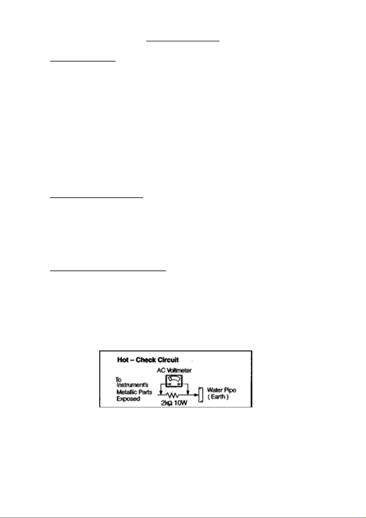
Leakage Current Hot Check ( Fig.1 )
1. Plug the AC cord directly into the AC outlet. Do not use an isolation transformer for this check.
2. Check a 2 kohm non-inductive resistor and an AC/DC current meter, in series with each exposed
metallic part on the receiver in turn and an earth such as a water pipe.
The current from any point should not exceed 0.7 mA peak AC or 2mA DC. In the case of a measurement being outside of these limits specified, there is a possibility of a shock hazard, and the receiver
should be repaired and rechecked before it is returned to the customer.
Fig.1
Page 4

X-Radiation
Warning :
The potential sources of X-Radiation in TV set
are the EHT section and the picture tube.
When using a picture tube test jig for service,
ensure that jig is capable of handling 28.1kV
without causing X-Radiati on.
Note : It is impo rtant to use an accurate
periodically calibrated high voltage
meter.
1. Set the brightness to minimum.
2. Use the remocon to get into Service Mode.
3. Measure the EHT. The meter reading should
indicate 28.0(+-1.0)kV. If the meter
indication is out of tolerance, immediate
service and correction is required to prevent
the possibility of premature component failure.
4. To prevent the possibility X-Radiation, it is
essential to use the specifield picture tube, if
service replacement becomes necessary.
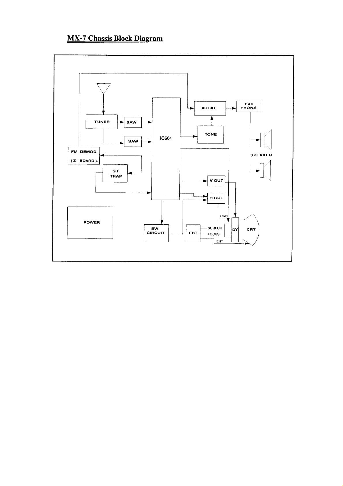
MX-7 Chassis Block Diagram
Page 5
Page 6
Service Hints.
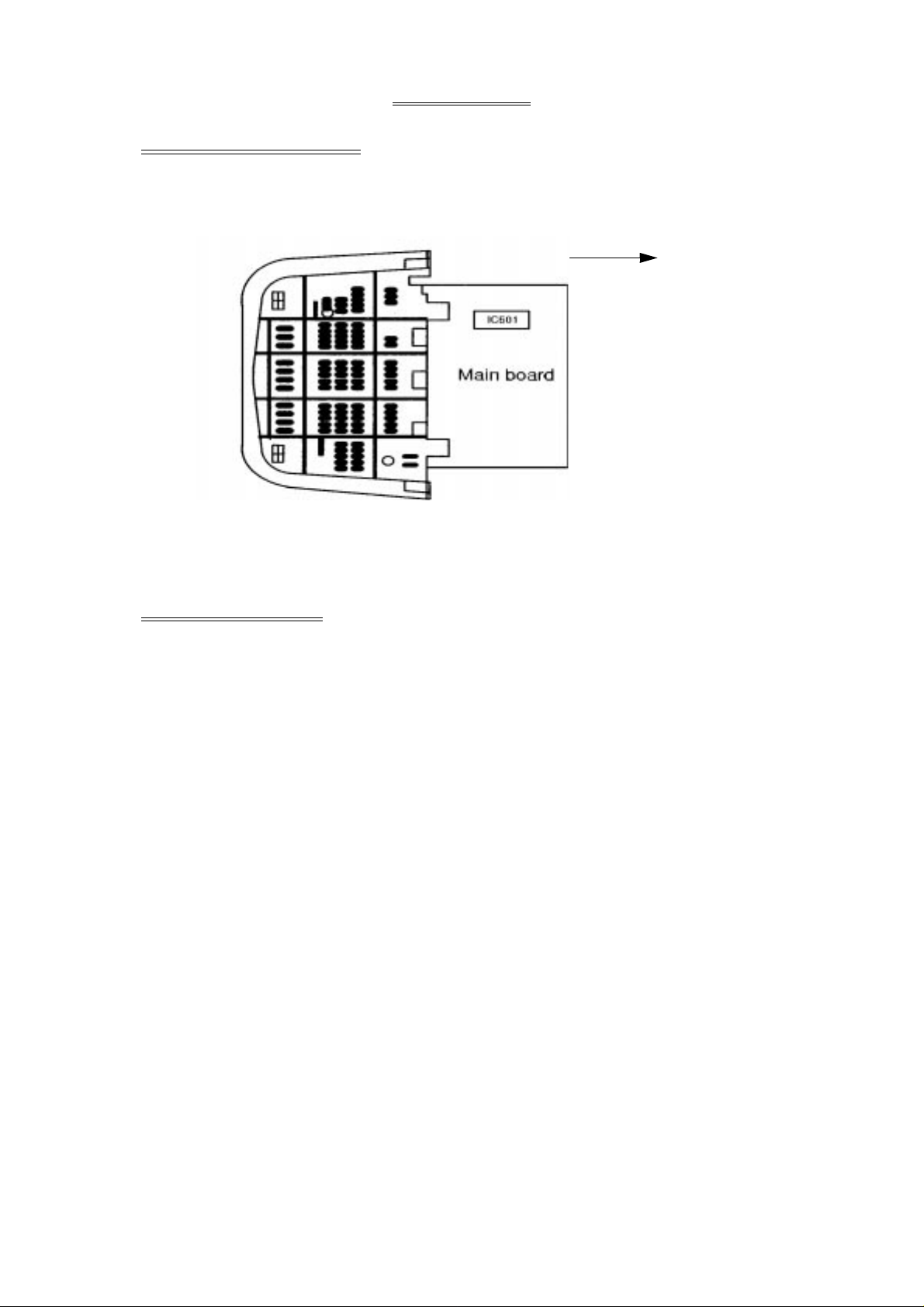
Service Position for E-Board
1. Remote the back cover.
2. Stand the TV set as shown in fig. 7.
3. Remove the A-Board from the TV set by pulling the main board out as shown in figure 7.
Pull out this way
Fig.7
Factory mode adjustment :
How To Set : To set the Factory mode, press Volume 0 dac on the TV and Timer Setting 30min
on the remote control and press Volume (-) Down button on the TV together press
recall on the remote control.
CHK should appear on right of TV screen.
To move from CHK1 to CHK2 mode, etc, please follow below rotation :
To Set Self-Check : Press the volume down button on TV than press the off timer button on
remote control.
Page 7
Adjustment for White Balance
Preparatio n :
1. Receive the white balance pattern and aging should have been performed over 30 minutes.
2. Set the picture menu to to DYNAMIC NORMAL.
3. Degause the CRT face.
4. Fix the CRT colour analyzer receiver unit to CRT face.
Adjustment of Low Light.
1. Adjustment Sub Bright, so that Y = 6.3 +- 1.0nit.
2. Adjust R-CUT OFF, so that X = 0.235 +- 0.01nit.
3. Adjust G-CUT OFF, so that y = 0.235 +- 0.01nit.
Adjustment of High Light.
1. Adjust Sub Bright, so that Y = 270 nit.
2. Adjust R-Drive, so that X = 0.265 +- 0.01nit.
3. Adjust B-Drive, so that y = 0.265 +- 0.01nit.
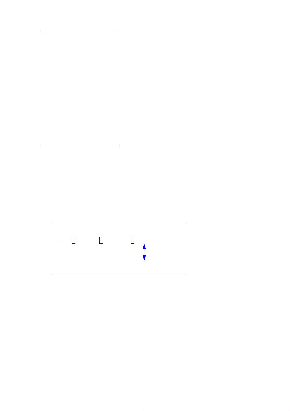
Adjustment for CRT CUT OFF.
Preparatio n :
1. Connect ocilloscope probe to TPL7.
2. Screen VR min.
3. Set the data Sub Bright , Bright.
4. In service Mode at ‘Bright’ dac press [5] in factory mode to enter vertical line and adjust by
volume down or up button.
5. Adjust “Screen VR” until 1-H Line appears.
130V
0V
Page 8
Adjustment Procedure
Item / Preparation Adjustment Procedure
+B Voltage
1. Operate the TV set. Confirm the DC voltage at the indicated test points,
as follow :
2. Set control as follow : TPA 12 : 141.2 +- 0.8V TPA 21 : 215 +- 15V
Brightness ..... minimum TPA 11 : 8 +- 1V
Contrast ........ minimum TPA 10 : 5 +- 1V
RF AGC
1. Receive a colour bar signal at an 1. Select “RF A GC” indi cation in CHK 2 , on Screen
RF level of 64(+0-1)dBU with 75 by remote control at factory mode.
loaded.
2. Connect digital multimeter to RF AGC 2. Set RF AGC by using remote control volume (+)
at Tuner. or volume (-) button until voltage AGC at Tuner
High Voltage
Ω
reach 2.7 +- 0.1V.
3. Increase RF signal strenght by 2dB, confirm
AGC at Tuner voltage drop.
1. Receive the crosshatch pattern. 1. Connect a DC voltage meter to TPA 12
and confirm the +B voltage is 141.2 +- 0.8V.
2. Set to 0 Beam . 2. Connect a high frequency voltmeter to heater and
Screen VR ..... minimum confirm that voltage reads 6.3+- 0.24 (VRMS).
Contrast ....... minimum 3. Normalize the brightness and contrast.
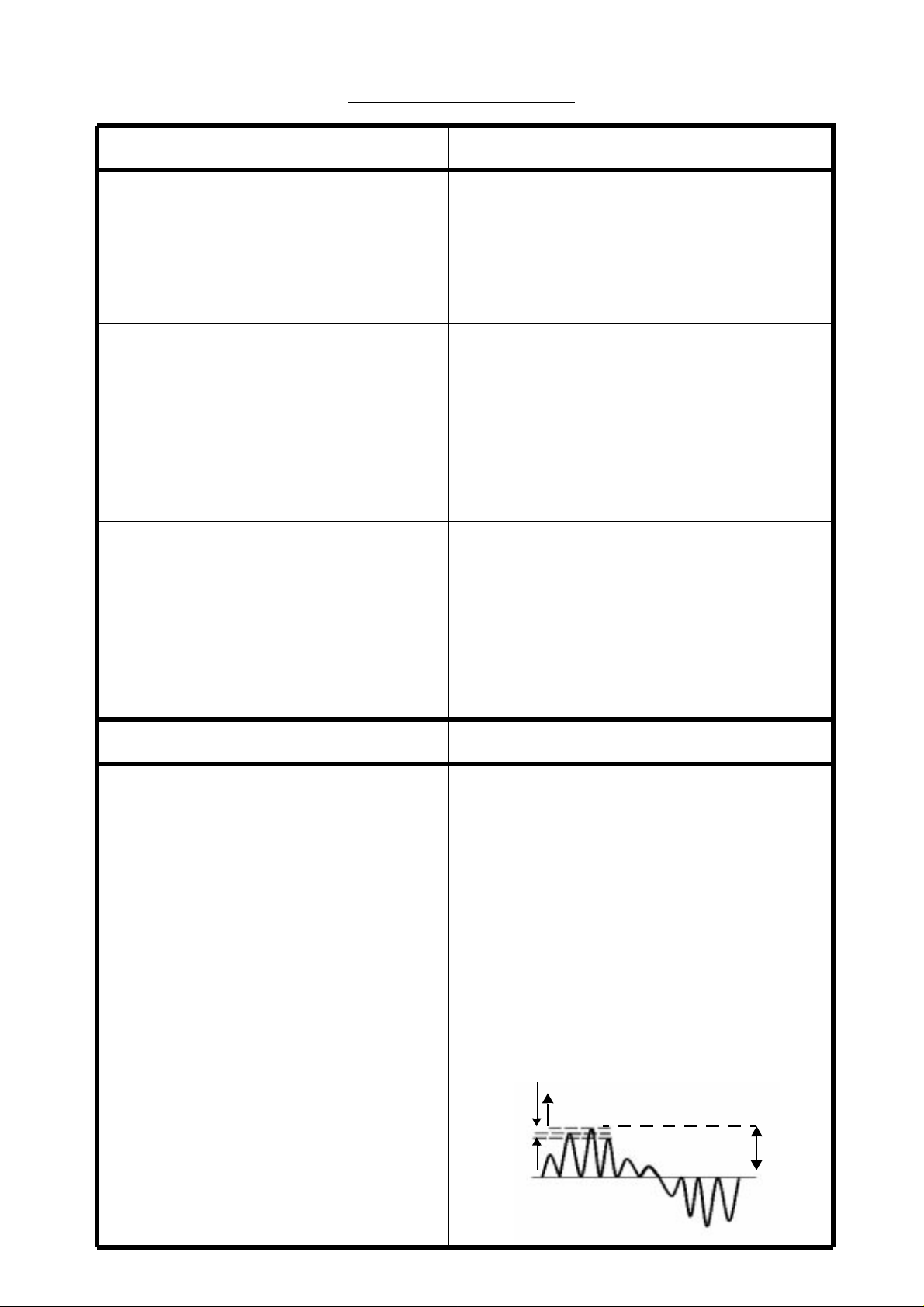
Item / Preparation Adjustment Produre
Connect oscilloscope probe to TPA32
(R-OUT) with 10Kohm series resistor.
Connect a short jumper between TPA 10 1. Adjust Sub-Tint so that No.2,3 and 4 becomes
and TPA 20. level waveform is similiar to Fig. 10.
Press Main Menu and Set system to 2. Confirm phase at Tint is changes more than
Use AV-NTSC (3.58MHz). +/- 30 by Tint control.
DYNAMIC ....... Normal 3. Confirm that colour level is maximum when
colour DAC is adjusted to maximum position.
Note:Use Remote control only when adjusting user mode
to Sub-Tint.
a
0.5a
7 8 9 10
1 2 3 4 5 6
Fig. 10
Page 9

Pal Colour
1. Receive the PAL B/G studio colour bar pattern, and adjust local frequency at the best tuned
position.
2. Pic Menu : Dynamic Normal , Confirm Contrast - 63 , Sub Contrast - 21.
3. Channel colour set ----------- STD.
4. Connect TPA 10 to TPA 20.
5. Set (A) to 2.3 +- 0.2V by BRT (CHK2) Fig. 1.
Adjustment
1. Connect oscilloscope probe to TPA 31 (G OUT) with 10k series resistor and adjust Contrast so
that (B) as in Fig.1 is 2.8 +- 0.1V.
2. Adjust ‘Sub Colour’ so that waveform as in Fig.1 (1) 2.55 +- 0.1V.
3. Connect oscilloscope probe to TPA 32 (R OUT) with 10k series resistor and confirm waveform as in
Fig.2 is (2).2.7 +- 0.4V
B
1
A
Fig. 1 Fig. 2
0V
2
A
Page 10

Before Colour Purity, Convergence and White Balance adjustment are attempted,
V. Height, H. Centre and Focus adjustments must be completed.
Colour Purity Convergence
1. Set the Brightness and Contrast controls to 1. Apply a crosshatch pattern signal and
their maximum postions. Normalize Contrast control to the
2. Operate the TV set for 30 minutes. maximum positions.
3. Fully degauss the picture tube by using an 2. Adjust Brightness until the grey position of
external degaussing coil. the crosshacth pattern just becomes black.
4. Apply a crosshatch pattern signal and adjust 3. Adjust the Red and Blue line at the centre of
the static convergence magnets to the the screen by rotating the R-B static
approximately correct position.
5. Receive a black and White signal.
6. S et the control as following:
Vertical
Convergence
Slide magnetic tabs toward or away from
each other.
Red ................ minimum
Green ............. minimum
Blue ............... minimum
Press the Shipping button on the remote control
Red & Blue
R-B Static
Convergence Magnet
twice to select CRT Adjustment Mode as per
Fig. 16 to select low light.
7. Loosen the clamp screw for the deflection yoke
A in Fig. 24 and move the deflection yoke as close
Horizontal
Convergence
Rotate both magnetic rings together.
to the purity magnet as possible.
8. Adjust the purity magnetic rings so that a vertical
green field is obtained at the cntre of the screen.
Red & Blue
R-B Static
Convergence Magnet
Fig.22
4. Adjust Red and Blue with Green line at
Colour Purity
5. Lock convergence magnetic with silicne
Green
centre of the screen by rotating (RB) -G
static convergence magnetic rings.
sealer.
6. Remove the DY wedges and slightly tilt the
deflection yoke vertically and horizontally to
Purity Magnet Green Field
obtain the good overall convergence.
Fig.20
Verti ca l
9. Slowly push the deflection yoke and set it where
a uniform green field is obtained.
BGR
R
G
B
R
G
B
RGB
BGR
Uniform
green
Horizontal
Fig. 21
10. Re-adjust the Low Light controls to their correct set-
tings and make sure that a uniform white field is
Fig. 23
obtained. 7. Fix the deflection yoke b y r e-inser ting t he DY
11. Tighten the clamp screw A in Fig. 24. wedges.Refer to Fig. 24.
8. If purity error is found, repeat “Colour
Purity” adjustment.
Page 11

Adjustment of CRT VRS
1. Preparation
a. Set DY to CRT not to tilt up and down left and right deflection.
b. Set CY to CRT and set CY magnet primarily (Fig.1)
Purity magnet : Set purity magnet that 2 magnet are (TOP POSITION)
VRS magnet : Set VRS magnet 2 magnet are (HORIZONTAL POSITION)
2. Adjustment
a. Receive that Cross Hatch pattern.
b. Adjust V-SHIFT - 50Hz.
c. Set 2 magnet of horizontal position to up and down equally so that center part of
CRT. (FIG.2)
Page 12

R-B Static
Convergence Magnet
25.3 mm
Clamp for
Convergence &
Purity Magnet
Deflection Yoke
Purity Magne
Fig. 24
Fig. 25
t
(RB)-G Static
Convergence Magnet
Note :
1. Wedge A,B and C should be inserted following the sequence of 1,2 and 3 shown
in Fig. 25.
2. The wedges should be set 120 apart from each other.
3. Be certain that four wedges are firmly fixed and the Deflection Yoke is tightly clamped
in place.
Otherwise the Deflection Yoke may shift its position and cause a loss of convergence
and purity.
°
Page 13

Page 14

Page 15

Page 16

Page 17

Page 18

Page 19

Page 20

Page 21

Page 22

Page 23

Replacement Parts List
Important Safety Notice
Components identified by mark have special characteristics important for safety.
∆
When replacing any of these components, use manufacturer’s specified parts.
Note : Printed circuit board assembly with “NLA” is no longer
available after production discontinuation of the complete set.
Abbreviation of part name and description
1. Resistor 2. Capacitor
Example : Example :
ERD25TJ104 C 100KOHM, J, 1/4W ECKF1H103ZF C 0.01UF, Z, 50V
Type Allowance Type Allowance
Type Allowance Type Allowance
C : Carbon F : +/- 1% C : Carbon C : +/- 0.25pF
F : Fuse G : +/- 2% E : Electrolytic D : +/- 0.5pF
M : Metal Oxide J : +/- 5% P : Polyester F : +/- 1pF
Metal Film K : +/- 10% Polypropylene G : +/- 3%
S : Solid M : +/- 20% T : Tantalum J : +/- 5%
W : Wire Wound K: +/- 10%
L : +/- 15%
M : +/- 20%
P : +100%, -0%
Z : +80%,-20%
Page 24

MECHANICAL PARTS
1 A51LSK955X-A PICTURE TUBE TXFKY01QL2S CABINET ASSY
2 EASG12D123N2 SPEAKER
(S'PORE,CIS ONLY)
3 ETC35C65NA CONVERGENCE YOKE TXFKY01QK2P CABINET ASSY
4 KDY3NWB63F DEFLECTION YOKE
(M'EAST ONLY)
5 TBL4G3404 SET LEG TXFPD02QL2S CUSHION (BOTTOM)
6 TBMA060 PANASONIC BADGE RESISTORS
7A TBM4G0630 MODEL NAME PLATE R003 ERJ6GEYJ100 M 10OHM,J,1/10W
(S'PORE ONLY) R004 ERG2SJ183E M 18KOHM,J, 2W
7B TBM4G0631 MODEL NAME PLATE R006 ERJ6GEYJ273 M 27KOHM,J,1/10W
(M'EAST ONLY) R007 ERJ6GEYJ302 M 3KOHM,J,1/10W
7C TBM4G0661 MODEL NAME PLATE R008 ERJ6GEYJ681 M 680OHM,J,1/10W
(CIS ONLY) R011 ERJ6GEYJ103 M 10KOHM,J,1/10W
8 TBX4G86500A 6 KEY BUTTON R012 ERJ6GEYJ332 M 3.3KOHM,J,1/10W
9 TBX4G87000 POWER BUTTON R021 ERJ6GEYJ273 M 27KOHM,J,1/10W
10 TJS2A8420 AC PLUG ADAPTOR R022 ERJ6GEYJ473 M 47KOHM,J,1/10W
(M'EAST ONLY) R116 ERJ6GEYJ222 M 2.2KOHM,J,1/10W
11 TEK4G902 DOOR CATCHER R117 ERJ6GEYJ682 M 6.8KOHM,J,1/10W
12 TES4G206 COIL SPRING R118 ERJ6GEYJ103 M 10KOHM,J,1/10W
13 THT4G1005R CRT SCREW R119 ERJ6GEYJ103 M 10KOHM,J,1/10W
14 THT4G1010R SCREW (SPEAKER) R120 ERJ6GEYJ680 M 68OHM,J,1/10W
15 TKK4G8538 LED PANEL R121 ERJ6GEYJ122 M 1.2KOHM,J,1/10W
16 TKK4G8540 POWER SWITCH SHAFT R122 ERJ6GEYJ470 M 47OHM,J,1/10W
17 TKP4G11744 AC CORD BRACKET R123 ERJ6GEYJ472 M 4.7KOHM,J,1/10W
18A TKP4G12041-1 DOOR R124 ERJ6GEYJ122 M 1.2KOHM,J,1/10W
(S'PORE,CIS ONLY) R125 ERJ6GEYJ1R0 M 1OHM,J,1/10W
18B TKP4G12131-1 DOOR R126 ERJ6GEYJ222 M 2.2KOHM,J,1/10W
(M'EAST ONLY) R136 ERJ6GEYJ103 M 10KOHM,J,1/10W
19 TKU4G8800-1 BACK COVER R137 ERJ6GEYJ683 M 68KOHM,J,1/10W
20 TLK4G9037S DEGAUSSING COIL R138 ERJ6GEYJ102 M 1KOHM,J,1/10W
21 TMM4G503 RUBBER WEDGE R139 ERJ6GEYJ333 M 33KOHM,J,1/10W
22 TMZ4G9808 CHASSIS RAIL (L) R145 ERJ6GEYJ473 M 47KOHM,J,1/10W
NLA TNP4G136AG A BOARD R150 ERJ6GEYJ222 M 2.2KOHM,J,1/10W
(S'PORE ONLY) R151 ERJ6GEYJ333 M 33KOHM,J,1/10W
NLA TNP4G136AF A BOARD R182 ERJ6GEYJ221 M 220OHM,J,1/10W
(M'EAST ONLY) R185 ERJ6GEYJ103 M 10KOHM,J,1/10W
NLA TNP4G136BD A BOARD R351 ER0S2CKF1001 M 1KOHM,F, 1/4W
(CIS ONLY) R352 ER0S2CKF1001 M 1KOHM,F, 1/4W
NLA TNP4G137AA L BOARD R353 ER0S2CKF1001 M 1KOHM,F, 1/4W
NLA TNP4G139AA Z1 BOARD R354 ER0S2CKF7870 M 787OHM,F, 1/4W
23 TNQ4G0401 REMOTE CONTROL R355 ER0S2CKF7870 M 787OHM,F, 1/4W
TPC4G45501 CARTON R356 ER0S2CKF7870 M 787OHM,F, 1/4W
(S'PORE ONLY) R363 ERC12GK222 S 2.2KOHM,K, 1/2W
TPC4G45502 CARTON R364 ERC12GK222 S 2.2KOHM,K, 1/2W
(M'EAST ONLY) R365 ERC12GK222 S 2.2KOHM,K, 1/2W
TPC4G45508 CARTON R369 ERDS2TJ103 C 10KOHM,J, 1/4W
(CIS ONLY) R374 ERQ12AJ181P F 180OHM,J, 1/2W
TPD4G1066 CUSHION (TOP) R401 ERDS2TJ1R8 C 1.8OHM,J, 1/4W
TPE4G14003 LAMI BAG R402 ERJ6GEYJ103 M 10KOHM,J,1/10W
(S'PORE,CIS ONLY) R403 ERJ6ENF2491 M2.49KOHM, 1/10W
TPE4G14025 SET COVER R404 ERJ6ENF2701 M 2.7KOHM, 1/10W
TQB4G1770 FAN BAG R405 ERJ6GEYJ272 M 2.7KOHM,J,1/10W
(S'PORE ONLY) R406 ERJ6GEYJ1R0 M 1OHM,J,1/10W
TQB4G1781 FAN BAG R407 ERJ12YJ331U M 330OHM,J, 1/2W
(M'EAST ONLY) R408 ERJ6GEY0R00 M 0OHM,J,1/10W
TQB4G1878 FAN BAG R409 ERJ6GEYJ823 M 82KOHM,J,1/10W
(CIS ONLY) R411 ERJ6GEYJ152 M 1.5KOHM,J,1/10W
24 TSM10032-3 MAGNET R412 ERJ6GEYJ332 M 3.3KOHM,J,1/10W
25 TSN63115-4 PURITY MAGNET R415 ERJ6GEYJ431 M 430OHM,J,1/10W
26A TSX4G111H AC POWER CORD R416 ERJ12YJ1R2U M 1.2OHM,J, 1/2W
(S'PORE,CIS ONLY) R417 ERJ12YJ1R2U M 1.2OHM,J, 1/2W
26B TSX4G112F AC POWER CORD R420 ERDS2TJ152 C 1.5KOHM,J, 1/4W
(M'EAST ONLY) R443 ERJ12YJ561U M 560OHM,J, 1/2W
Page 25

R444 ERDS2TJ152 C 1.5KOHM,J, 1/4W R638 ERJ6GEYJ391 M 390OHM,J,1/10W
R445 ERJ6GEYJ473 M 47KOHM,J,1/10W R639 ERJ6GEYJ101 M 100OHM,J,1/10W
R446 ERJ6GEYJ473 M 47KOHM,J,1/10W R640 ERJ6GEYJ181 M 180OHM,J,1/10W
R447 ERJ6GEYJ472 M 4.7KOHM,J,1/10W R641 ERJ6GEY0R00 M 0OHM,J,1/10W
R448 ERJ6GEYJ242 M 2.4KOHM,J,1/10W R642 ERJ6GEYJ332 M 3.3KOHM,J,1/10W
R449 ERJ6GEYJ152 M 1.5KOHM,J,1/10W R643 ERJ6GEYJ272 M 2.7KOHM,J,1/10W
R502 ERJ6GEYJ182 M 1.8KOHM,J,1/10W R647 ERJ6GEYJ101 M 100OHM,J,1/10W
R503 ERJ6GEY0R00 M 0OHM,J,1/10W R654 ERJ6GEYJ473 M 47KOHM,J,1/10W
R504 ERG2SJ682E M 6.8KOHM,J, 2W R655 ERJ6GEYJ103 M 10KOHM,J,1/10W
R507 ERJ6GEYJ101 M 100OHM,J,1/10W R660 ERJ6GEYJ274 M 270KOHM,J,1/10W
R508 ERG3FJ102 M 1KOHM,J, 3W R661 ERJ6GEYJ103 M 10KOHM,J,1/10W
R509 ERG3FJ122 M 1.2KOHM,J, 3W R662 ERJ6GEYJ333 M 33KOHM,J,1/10W
R511 ERJ6ENF1201 M 1.2KOHM, 1/10W R701 ERQ12AJ150E F 15OHM,J, 1/2W
R512 ERJ6ENF1741 M1.74KOHM, 1/10W R703 ERG2SJ821E M 820OHM,J, 2W
R513 ERQ14AJ100P F 10OHM,J, 1/4W R704 ERJ6GEYJ563 M 56KOHM,J,1/10W
R520 ERX12SJ3R0E M 3OHM,J, 1/2W R705 ERJ6GEYJ104 M 100KOHM,J,1/10W
R521 ERX12SJ3R0E M 3OHM,J, 1/2W R706 ERJ6GEYJ472 M 4.7KOHM,J,1/10W
R522 ERJ6GEYJ123 M 12KOHM,J,1/10W R707 ERJ6GEYJ681 M 680OHM,J,1/10W
R523 ERJ6GEYJ103 M 10KOHM,J,1/10W R708 ERJ6GEYJ393 M 39KOHM,J,1/10W
R524 ERJ6GEYJ104 M 100KOHM,J,1/10W R709 ERJ6GEYJ393 M 39KOHM,J,1/10W
R525 ERJ6GEYJ392 M 3.9KOHM,J,1/10W R710 ERJ6GEYJ273 M 27KOHM,J,1/10W
R553 ERJ6GEYJ223 M 22KOHM,J,1/10W R711 ERG1SJ101E M 100OHM,J, 1W
R555 ERQ14AJ2R0E F 2.0OHM,J, 1/4W R712 ERJ6GEYJ102 M 1KOHM,J,1/10W
R557 ER050CKF9532 M95.3KOHM,F, 1/2W R713 ERQ2CJP8R2S F 8.2OHM,J, 2W
R558 ERDS2TJ223 C 22KOHM,J, 1/4W R721 ERJ6GEYJ752 M 7.5KOHM,J,1/10W
R559 ERQ1CJP3R3S F 3.3OHM,J, 1W R801 ERF15ZK1R5 M 1.5OHM, 15W
R560 ERG1SJ102E M 1KOHM,J, 1W R805 ERG2SJ470E M 47OHM,J, 2W
R601 ERJ6GEYJ153 M 15KOHM,J,1/10W R806 ERJ6GEYJ152 M 1.5KOHM,J,1/10W
R602 ERJ6ENF3001 M 3KOHM, 1/10W R807 ERJ6GEYJ222 M 2.2KOHM,J,1/10W
R603 ERJ6GEYJ393 M 39KOHM,J,1/10W R809 ERX12SJR27E M 0.27OHM,J, 1/2W
R604 ERJ6GEYJ101 M 100OHM,J,1/10W R811 ERJ6GEYJ681 M 680OHM,J,1/10W
R605 ERJ6GEYJ101 M 100OHM,J,1/10W R812 ERD75TAJ825 C 8.2MOHM,J, 3/4W
R606 ERJ6GEYJ101 M 100OHM,J,1/10W R814 ERJ6GEYJ332 M 3.3KOHM,J,1/10W
R607 ERJ6GEYJ103 M 10KOHM,J,1/10W R815 ERJ6GEYJ102 M 1KOHM,J,1/10W
R608 ERJ6GEYJ332 M 3.3KOHM,J,1/10W R817 ERG5FJ183H M 18KOHM,J, 5W
R609 ERJ6GEYJ332 M 3.3KOHM,J,1/10W R819 ERJ12YJ330U M 33OHM,J, 1/2W
R610 ERJ6GEYJ103 M 10KOHM,J,1/10W R824 ERDS1TJ474 C 4.7KOHM,J, 1/2W
R611 ERJ6GEYJ472 M 4.7KOHM,J,1/10W R825 ERJ6GEYJ473 M 47KOHM,J,1/10W
R612 ERJ6GEYJ102 M 1KOHM,J,1/10W R832 ERJ12YJ221U M 220OHM,J, 1/2W
R613 ERJ6GEYJ391 M 390OHM,J,1/10W R835 ERX12SJR33E M 0.33OHM,J, 1/2W
R614 ERJ6GEYJ272 M 2.7KOHM,J,1/10W R850 ERQ12AJ3R3E F 3.3OHM,J, 1/2W
R615 ERJ6GEYJ102 M 1KOHM,J,1/10W R853 ERJ14YJ102U M 1KOHM,J, 1/4W
R616 ERJ6GEYJ392 M 3.9KOHM,J,1/10W R856 ERQ12HKR22P F 0.22OHM,K, 1/2W
R617 ERJ6GEYJ181 M 180OHM,J,1/10W R857 ERF3EXKR33V W 0.33OHM,K, 3W
R618 ERJ6GEYJ184 M 180KOHM,J,1/10W R859 ERJ6GEYJ152 M 1.5KOHM,J,1/10W
R619 ERJ6GEYJ121 M 120OHM,J,1/10W R860 ERJ6ENF6801 M 6.8KOHM, 1/10W
R620 ERJ6GEYJ121 M 120OHM,J,1/10W R861 ERJ6GEYJ103 M 10KOHM,J,1/10W
R621 ERJ6GEYJ103 M 10KOHM,J,1/10W R862 ERJ6GEYJ103 M 10KOHM,J,1/10W
R622 ERJ6GEYJ103 M 10KOHM,J,1/10W R863 ERG3FJ473H M 47KOHM,J, 3W
R623 ERJ6GEYJ331 M 330OHM,J,1/10W R864 ERJ6GEYJ103 M 10KOHM,J,1/10W
R624 ERJ6GEYJ103 M 10KOHM,J,1/10W R866 ERJ6GEYJ472 M 4.7KOHM,J,1/10W
R625 ERJ6GEYJ222 M 2.2KOHM,J,1/10W R867 ERJ6GEYJ103 M 10KOHM,J,1/10W
R626 ERJ6GEYJ104 M 100KOHM,J,1/10W R868 ERJ6GEYJ472 M 4.7KOHM,J,1/10W
R627 ERJ6GEYJ683 M 68KOHM,J,1/10W R1016 ERJ6ENF1651 M1.65KOHM, 1/10W
R628 ERJ6GEYJ563 M 56KOHM,J,1/10W R1017 ERJ6ENF2151 M2.15KOHM, 1/10W
R629 ERJ6GEYJ154 M 150KOHM,J,1/10W R1018 ERJ6ENF3091 M3.09KOHM, 1/10W
R630 ERJ6ENF1802 M 18KOHM, 1/10W R1019 ERJ6ENF4421 M4.42KOHM, 1/10W
R631 ER050CKF5603 M 560KOHM,F, 1/2W R1020 ERJ6ENF7501 M 7.5KOHM, 1/10W
R632 ERJ6GEYJ750 M 75OHM, 1/10W R1021 ERJ6ENF1871 M1.87KOHM, 1/10W
R634 ERJ6GEYJ822 M 8.2KOHM,J,1/10W R1022 ERJ6GEYJ100 M 10OHM,J,1/10W
R635 ERJ6GEYJ561 M 560OHM,J,1/10W R1101 ERJ6GEYJ332 M 3.3KOHM,J,1/10W
R636 ERJ6GEYJ562 M 5.6KOHM,J,1/10W R1102 ERJ6GEYJ153 M 15KOHM,J,1/10W
R637 ERJ6GEYJ473 M 47KOHM,J,1/10W R1103 ERJ6GEYJ103 M 10KOHM,J,1/10W
Page 26

R1104 ERJ6GEYJ562 M 5.6KOHM,J,1/10W C121 ECJ2VF1H103Z C 0.01UF, Z, 50V
S
R1105 ERJ6GEYJ562 M 5.6KOHM,J,1/10W C122 ECJ2VF1H103Z C 0.01UF, Z, 50V
R1106 ERJ6GEYJ102 M 1KOHM,J,1/10W C136 ECJ2VF1H103Z C 0.01UF, Z, 50V
R1117 ERJ6GEYJ471 M 470OHM,J,1/10W C180 ECJ2VG1H151J C 150PF, J, 50V
R1120 ERJ6GEYJ432 M 4.3KOHM,J,1/10W C354 ECCF1H330JC C 33PF, J, 50V
R1122 ERJ6GEYJ332 M 3.3KOHM,J,1/10W C355 ECCF1H330JC C 33PF, J, 50V
R1123 ERJ6GEYJ202 M 2KOHM,J,1/10W C356 ECCF1H330JC C 33PF, J, 50V
R1124 ERJ6GEYJ101 M 100OHM,J,1/10W C357 ECA160V33UE E 33UF, 160V
R1140 ERJ6ENF1002 M 10KOHM, 1/10W C359 ECQM4104KZ P 0.1UF, K,400V
R1141 ERJ6GEYJ562 M 5.6KOHM,J,1/10W C368 ECCF1H561J C 560PF, J, 50V
R1143 ERJ6GEYJ103 M 10KOHM,J,1/10W C370 ECKW3D102KBP C 1000PF, K, 2KV
R2022 ERJ6GEYJ104 M 100KOHM,J,1/10W C371 ECEA1CN100U E 10UF, 16V
R2211 ERJ6GEYJ471 M 470OHM,J,1/10W C373 ECA2EM100B E 10UF, 250V
R2212 ERJ6GEYJ471 M 470OHM,J,1/10W C377 ECA1CM221B E 220UF, 16V
R2213 ERJ6GEYJ471 M 470OHM,J,1/10W C402 EEUFC1V222E E 2200UF, 35V
R2214 ERJ6GEYJ471 M 470OHM,J,1/10W C403 ECA1HHG220 E 22UF, 50V
R2215 ERJ6GEYJ153 M 15KOHM,J,1/10W C406 ECA1HHG101 E 100UF, 50V
R2216 ERJ6GEYJ273 M 27KOHM,J,1/10W C408 ECQV1H274JL P 0.27UF, J, 50V
R2217 ERJ6GEY0R00 M 0OHM,J,1/10W C409 EEUFC1H330B E 33UF, 50V
R2218 ERJ6GEYJ272 M 2.7KOHM,J,1/10W C502 ECKR2H821KB5 C 820PF, K,500V
R2308 ERJ6GEYJ103 M 10KOHM,J,1/10W C504 ECJ2VB1H681K C 680PF, K, 50V
R2309 ERJ6GEYJ822 M 8.2KOHM,J,1/10W C506 L5SL4B100D C 10PF, 500V
R2356 ERJ6GEYJ103 M 10KOHM,J,1/10W C511 ECA1VM101B E 100UF, 35V
R2380 ERJ6GEYJ151 M 150OHM,J,1/10W C520 ECA0JM221B E 220UF, 6.3V
R2381 ERJ6GEYJ102 M 1KOHM,J,1/10W C552 ECA2EHG100 E 10UF, 250V
R2382 ERJ6GEYJ102 M 1KOHM,J,1/10W C555 ECKR2H471KB5 C 470PF, K,500V
R2401 ERJ6GEYJ822 M 8.2KOHM,J,1/10W C558 ECA2CMR47B E 0.47UF, 160V
R2402 ERJ6GEYJ333 M 33KOHM,J,1/10W C559 ECWH16912JVB P 9100PF,J,1.6KV
R2403 ERJ6GEYJ154 M 150KOHM,J,1/10W C560 ECQM4273JZ P 0.027UF, 400V
R2404 ERJ6GEYJ681 M 680OHM,J,1/10W C561 ECKW3D331JBP C 330PF, J, 2KV
R2405 ERJ6GEYJ684 M 680KOHM,J,1/10W C562 ECKW3D471JBP C 470PF, J, 2KV
R2406 ERJ6GEYJ334 M 330KOHM,J,1/10W C563 ECWF2224JSR P 0.22UF, J,250V
R2407 ERJ6GEYJ333 M 33KOHM,J,1/10W C565 ECQP1H183JZ P 0.018UF, J, 50V
R2408 ERJ6GEYJ683 M 68KOHM,J,1/10W C570 ECUX1H820JCX C 82PF, J, 50V
R2410 ERJ6GEYJ473 M 47KOHM,J,1/10W C601 ECEA1CKA101 E 100UF, 16V
R2411 ERJ6GEYJ563 M 56KOHM,J,1/10W C602 ECUX1H104KBX C 0.1UF, K, 50V
R2412 ERJ6GEYJ103 M 10KOHM,J,1/10W C603 ECJ2VB1H472K C 4700PF, K, 50V
R2413 ERJ6GEYJ103 M 10KOHM,J,1/10W C604 ECQV1H224JL P 0.22UF, J, 50V
R2414 ERJ6GEYJ103 M 10KOHM,J,1/10W C605 ECQV1H224JL P 0.22UF, J, 50V
R2415 ERJ6GEYJ102 M 1KOHM,J,1/10W C606 ECJ2VC1H222J C 2200PF, J, 50V
R2416 ERJ6GEYJ182 M 1.8KOHM,J,1/10W C607 ECEA1HKA010 E 1UF, 50V
R2417 ERJ6GEYJ273 M 27KOHM,J,1/10W C608 ECEA1HKA2R2 E 2.2UF, 50V
R2418 ERJ6GEYJ821 M 820OHM,J,1/10W C609 ECUX1H104KBX C 0.1UF, K, 50V
R2419 ERJ6GEYJ273 M 27KOHM,J,1/10W C610 ECJ2VB1H103J C 0.01UF, 50V
R2420 ERJ6GEYJ272 M 2.7KOHM,J,1/10W C612 ECJ2VB1H472K C 4700PF, K, 50V
R2421 ERJ6GEYJ332 M 3.3KOHM,J,1/10W C613 ECJ2VB1H472K C 4700PF, K, 50V
R3003 ERJ6GEYJ101 M 100OHM,J,1/10W C614 ECQV1H104JL P 0.1UF, J, 50V
R3014 ERD25V0R00T C 0OHM, 1/4W C615 ECQV1H224JL P 0.22UF, J, 50V
R3019 ERJ6GEYJ104 M 100KOHM,J,1/10W C617 ECEA1CKA100 E 10UF, 16V
R3024 ERJ6GEYJ560 M 56OHM,J,1/10W C618 ECKR1H821KB5 C 820PF, K, 50V
R3025 ERJ6GEYJ103 M 10KOHM,J,1/10W C620 ECUX1H470JCX C 47PF, J, 50V
R3132 ERJ6GEYJ221 M 220OHM,J,1/10W C622 ECJ2VF1H104Z C 0.1UF, Z, 50V
R3133 ERJ6GEYJ221 M 220OHM,J,1/10W C623 ECUX1H470JCX C 47PF, J, 50V
CAPACITOR
C624 ECEA1CKA100 E 10UF, 16V
C001 ECEA1CKA220 E 22UF, 16V C627 ECJ2YB1H473K C 0.047UF, K, 50V
C002 ECJ2VF1H104Z C 0.1UF, Z, 50V C628 ECJ2YB1H473K C 0.047UF, K, 50V
C005 ECJ2VF1H104Z C 0.1UF, Z, 50V C629 ECUX1H104KBX C 0.1UF, K, 50V
C006 ECA1AM331B E 330UF, 10V C631 ECJ2VB1H472K C 4700PF, K, 50V
C008 ECEA1HKA010 E 1UF, 50V C633 ECJ2ZF1C105Z C 1UF, Z, 16V
C109 ECJ2VF1H103Z C 0.01UF, Z, 50V C634 ECJ2ZF1C105Z C 1UF, Z, 16V
C116 ECJ2VF1H103Z C 0.01UF, Z, 50V C635 ECJ2VF1H104Z C 0.1UF, Z, 50V
C117 ECJ2VB1H103J C 0.01UF, 50V C636 ECEA1CKA101 E 100UF, 16V
C120 ECJ2VF1H103Z C 0.01UF, Z, 50V C639 ECA1HM220B E 22UF, 50V
Page 27

C641 ECJ2VC1H100C C 10PF, C, 50V C2380 ECA1CM101B E 100UF, 16V
C653 ECEA1CKA100 E 10UF, 16V C2401 ECJ2VB1H472K C 4700PF, K, 50V
C654 ECJ2VB1H103J C 0.01UF, 50V C2402 ECJ2ZF1C105Z C 1UF, Z, 16V
C660 ECQV1H105JM P 1UF, J, 50V C2403 ECJ2ZF1C105Z C 1UF, Z, 16V
C701 ECA1HHG101 E 100UF, 50V C2404 ECJ2VB1E104K C 0.1UF, K, 25V
C703 ECEA1HGE100 E 10UF, 50V C2405 ECEA1HKAR33 E 0.33UF, 50V
C704 ECQB1H223JM P 0.022UF, J, 50V C2406 ECJ2VB1H102J C 1000PF, 50V
C705 ECQB1H122KM P 1200PF, K, 50V C2420 ECJ2ZF1C105Z C 1UF, Z, 16V
C801 ECKCNA102MB7 C 1000PF, M, C3016 ECA1CM471B E 470UF, 16V
C802 ECKCNA101MB7 C 100PF, M, C3024 ECA1HM010B E 1UF, 50V
C803 ECKWAE472ZE C 4700PF, Z, C3111 ECJ2VC1H561K C 560PF, K, 50V
C804 ECKW3D102JBP C 1000PF, J, 2KV C3113 ECJ2VC1H561K C 560PF, K, 50V
C805 B81130C1224M P 0.22UF, 275V C3116 ECJ2VB1H103J C 0.01UF, 50V
C806 ECKWAE472ZE C 4700PF, Z, C3117 ECJ2VB1H103J C 0.01UF, 50V
C807 ECKCNA472ME7 C 4700PF, M, C3131 ECJ2YB1A105K C 1UF, K,
C808 ECQB1H151KM P 150PF, K, 50V C3132 ECJ2YB1A105K C 1UF, K,
C809 ECKCNA472ME7 C 4700PF, M, C3133 ECJ2YB1A105K C 1UF, K,
C811 EEUFC1E470B E 47UF, 25V C3134 ECJ2YB1A105K C 1UF, K,
C813 ECKCNA332MEB C 3300PF, M, COILS
C814 ECKR1H471KB5 C 470PF, K, 50V L001 TLTACT100K PEAKING COIL 10U
C816 ECQE2A473JF P 0.047UF, J,250V L120 TLTACTR56K PEAKING COIL
C817 B81130C1224M P 0.22UF, 275V L181 TLTACT100K PEAKING COIL 10U
C818 ECKCNA102MB7 C 1000PF, M, L182 TALV35VB6R8K PEAKING COIL
C824 EETED2G271J E 270UF, 400V L183 TALV35VB5R6K PEAKING COIL
C826 ECA2CHG100 E 10UF, 160V L184 TALV35VB6R8K PEAKING COIL
C831 ECKR3A271KBP C 270PF, K, 1KV L352 EXCELSA24T BEAD CORE
C840 ECJ2YB1C474K C 0.47UF, K, 16V L501 ELH5L4129 LINEARITY COIL
C841 ECJ2YB1A824K C 0.82UF, K, L550 EXCELDR25V CORE
C851 ECJ2ZF1C105Z C 1UF, Z, 16V L551 TSK1045 BEAD CORE
C852 ECKW3D101KBP C 100PF, K, 2KV L552 TSK1045 BEAD CORE
C853 ECKR2H151KB5 C 150PF, K,500V L620 TSK1045 BEAD CORE
C854 ECQB1H104JM P 0.1UF, 50V L701 ELC10D472E CHOKE COIL
C855 ECJ2ZF1C105Z C 1UF, Z, 16V L801 ELF24V019A LINE FILTER
C856 ECKR2H151KB5 C 150PF, K,500V L802 EXCELDR35C BEAD CORE
C857 EEUFC1C471LB E 470UF, 16V L803 EXCELDR35C BEAD CORE
C859 EEUFC1E222E E 2200UF, 25V L820 EXCELDR35C BEAD CORE
C860 EEUFC1C332E E 3300UF, 16V L852 EXCELDR35C BEAD CORE
C861 ECA1VMH102 E 1000UF, 35V L856 TLTACT1R5K PEAKING COIL
C862 ECEA1CKA100 E 10UF, 16V L857 TLTACT1R5K PEAKING COIL
C863 ECKR2H271KB5 C 270PF, K,500V L1101 TALV35VB331K PEAKING COIL
C865 EEUEB2C221SE E 220UF, 160V L2211 TLTACT100K PEAKING COIL 10U
C866 ECKR3A221JBP C 220PF, J, 1KV TRANSFORMERS
C971 ECKF1H103ZF C 0.01UF, Z, 50V T552 ZTFN32001A FLYBACK TRANS
C1101 ECJ2VF1H104Z C 0.1UF, Z, 50V T553 ETH19Y70AY H DRIVE TRANS
C1103 ECJ2VC1H331J C 330PF, J, 50V T801 ETS29AS126AD SWITCHING TRANS
C1104 ECA1CM101B E 100UF, 16V DIODES
C1105 ECJ2VF1H104Z C 0.1UF, Z, 50V D002 MTZJ16A ZENER DIODE
C1106 ECJ2VF1H103Z C 0.01UF, Z, 50V D003 MTZJ16A ZENER DIODE
C1203 ECJ2VF1H104Z C 0.1UF, Z, 50V D011 MA152KTX DIODE
C1204 ECEA1CKA101 E 100UF, 16V D120 MA858 DIODE
C1205 ECA1CM101B E 100UF, 16V D354 1SS133T77 DIODE
C2210 ECJ2VF1H223Z C 0.022UF, Z, 50V D355 1SS133T77 DIODE
C2211 ECJ2VF1H103Z C 0.01UF, Z, 50V D356 1SS133T77 DIODE
C2212 ECA1HM100B E 10UF, 50V D360 ERA22-04 DIODE
C2213 ECA1HM2R2B E 2.2UF, 50V D361 ERA22-04 DIODE
C2214 ECA1HM2R2B E 2.2UF, 50V D362 ERA22-04 DIODE
C2215 ECA1HM2R2B E 2.2UF, 50V D363 1SS133T77 DIODE
C2307 ECEA1HKN010 E 1UF, 50V D365 MTZJ10C ZENER DIODE
C2308 ECJ2VC1H391J C 390PF, J, 50V D375 1SS133T77 DIODE
C2352 ECA1HM010B E 1UF, 50V D402 D1FL20UF4063 DIODE
C2353 ECA1CM100B E 10UF, 16V D403 MTZJ33B ZENER DIODE
C2354 ECA1CM471B E 470UF, 16V D511 MA4108J DIODE
C2357 ECEA1HKN010 E 1UF, 50V D512 MA171 DIODE
Page 28

D520 MA152KTX DIODE Q101 2SC2412KT TRANSISTOR
D551 MA3047HTX DIODE Q102 2SC4787 TRANSISTOR
D552 D1FL40F4063 DIODE Q103 2SD2114KT TRANSISTOR
D555 MA152KTX DIODE Q105 2SC2412KT TRANSISTOR
D556 ERD07-15 DIODE Q180 2SA1037AKT TRANSISTOR
D557 TVSRU2AM DIODE Q369 2SA564AQR TRANSISTOR
D558 MA185 DIODE Q401 2SA1037AKT TRANSISTOR
D603 MA152KTX DIODE Q445 2SC3326ATX TRANSISTOR
D606 MA152KTX DIODE Q446 2SC2412KT TRANSISTOR
D660 MA152WKTX DIODE Q447 2SC2412KT TRANSISTOR
D701 1SS133T77 DIODE Q501 2SC4212H TRANSISTOR
D702 MTZJ3.6A ZENER DIODE Q520 2SB792ATX TRANSISTOR
D704 MA29T-B DIODE Q551 2SD2553 TRANSISTOR
D705 MTZJ5.6A ZENER DIODE Q601 2SA1037AKT TRANSISTOR
D801 TRPW5B0N120D POSISTOR Q602 2SC2412KT TRANSISTOR
D802 D4SB80 DIODE Q603 2SA1037AKT TRANSISTOR
D804 MA167 DIODE Q605 2SC2412KT TRANSISTOR
D805 D1FL20UF4063 DIODE Q606 2SC2412KT TRANSISTOR
D806 ERZV10V621CS VARISTOR Q607 2SA1037AKT TRANSISTOR
D807 TLP721FD4GR PHOTO COUPLER Q608 2SC2412KT TRANSISTOR
D809 D1FL40F4063 DIODE Q701 2SA1037AKT TRANSISTOR
D811 AM01A DIODE Q801 2SK1006RF122 TRANSISTOR
D815 D1FL20UF4063 DIODE Q850 2SC1815 TRANSISTOR
D816 D1FL20UF4063 DIODE Q852 2SC2412KT TRANSISTOR
D817 MA2560 DIODE Q853 2SC2412KT TRANSISTOR
D824 MA4068M DIODE Q854 2SC2412KT TRANSISTOR
D831 FMLG16S DIODE Q855 2SC1815 TRANSISTOR
D837 S3L60P1520 DIODE Q856 2SC2412KT TRANSISTOR
D852 AU02A DIODE Q1101 2SC2412KT TRANSISTOR
D853 MCR22-6 THYRISTOR Q2380 DTD113ZKT TRANSISTOR
D854 D1FL20UF4063 DIODE Q2381 2SA1037AKT TRANSISTOR
D855 D1FL20UF4063 DIODE Q2401 2SC2412KT TRANSISTOR
D856 RN1ZLF-A1 DIODE Q2402 2SC2412KT TRANSISTOR
D857 D1FL20UF4063 DIODE Q2403 2SC2412KT TRANSISTOR
D862 MTZJ6.2C ZENER DIODE Q2404 2SC2412KT TRANSISTOR
D863 MTZJ18B ZENER DIODE Q2405 2SC2412KT TRANSISTOR
D865 MTZJ24B ZENER DIODE Q2406 2SC2412KT TRANSISTOR
D1101 MA152WKTX DIODE Q2407 2SC2412KT TRANSISTOR
D1102 MTZJ5.6A ZENER DIODE OTHERS
D1104 LNH201RGRF5 LED A1 TJS4G9010 CONNECTOR
D1105 MTZJ7.5C ZENER DIODE A3 K1KA02A00235 CONNECTOR
D1120 MA152KTX DIODE A5 TJS3A9670 6P CONNECTOR
D1204 MTZJ5.6B ZENER DIODE A8 TJS3A9880 8P CONNECTOR
D2380 MA152KTX DIODE A9 TJS4G8090 20P CONNECTOR
D2381 MA152KTX DIODE DYH K1KA03A00216 CONNECTOR
DYV TJS3A9640 3P CONNECTOR
INTEDGRATED CIRCUITS
IC351 TDA6107Q/N2 LINEAR IC F801 XBA2C31TR0 FUSE 250V 3.15A
IC451 LA7840 LINEAR IC JA1 ERJ6GEY0R00 M 0OHM,J,1/10W
IC601 TDA9353S064E IC JA3 ERJ6GEY0R00 M 0OHM,J,1/10W
IC701 TEA2031A IC JK351 TJSC01200 CRT SOCKET
IC801 STRF6656LF53 LINEAR IC JK3001 TJB4G633 REAR AV TERMINAL
IC802 SE140N LINEAR IC JK3101 TJB4G640 AV TERMINAL
IC851 AN7805 LINEAR IC JS1 ERJ6GEY0R00 M 0OHM,J,1/10W
IC852 AN7808 LINEAR IC JS2 ERJ6GEY0R00 M 0OHM,J,1/10W
IC1102 MN13812-JTA MOS IC JS19 ERJ6GEY0R00 M 0OHM,J,1/10W
IC1103 TVR4GAS058 IC (EEPROM) JS20 ERJ6GEY0R00 M 0OHM,J,1/10W
IC1104 RPM6937 REMOTE CONTROL R JS24 ERJ6GEY0R00 M 0OHM,J,1/10W
IC1201 PQ1R33 LINEAR IC JS28 ERJ6GEY0R00 M 0OHM,J,1/10W
IC1202 AN78L05 LINEAR IC JS31 ERJ6GEY0R00 M 0OHM,J,1/10W
IC2201 TDA9820T/V1 IC JS34 ERJ6GEY0R00 M 0OHM,J,1/10W
IC2303 AN7522 LINEAR IC JS35 ERJ6GEY0R00 M 0OHM,J,1/10W
TRANSISTORS JS41 ERJ6GEY0R00 M 0OHM,J,1/10W
Q001 2SC2412KT TRANSISTOR JS42 ERJ6GEY0R00 M 0OHM,J,1/10W
Page 29

JS551 ERJ6GEY0R00 M 0OHM,J,1/10W
JS2201 ERJ6GEY0R00 M 0OHM,J,1/10W
JS2202 ERJ6GEY0R00 M 0OHM,J,1/10W
JS2205 ERJ6GEY0R00 M 0OHM,J,1/10W
JS3010 ERJ6GEY0R00 M 0OHM,J,1/10W
JS3101 ERJ6GEY0R00 M 0OHM,J,1/10W
L5 TJS3A9670 6P CONNECTOR
L8 TJS3A9880 8P CONNECTOR
S801 ESB92DA1B SWITCH
S1001 EVQ11G05R SWITCH
S1002 EVQ11G05R SWITCH
S1003 EVQ11G05R SWITCH
S1004 EVQ11G05R SWITCH
S1005 EVQ11G05R SWITCH
S1006 EVQ11G05R SWITCH
TNR001ENV59D82G3D TUNER
X101 K7256M SAW FILTER
X180 EFCS5M7MW3 CERAMIC FILTER
X181 EFCS6R0MW5 CERAMIC FILTER
X182 EFCS6R5MW5 CERAMIC FILTER
X183 EFCS4R5MW5 CERAMIC FILTER
X601 TSSA010 CRYSTAL OSCILLATOR
X2201 SFSH6R0MDB CERAMIC FILTER
X2202 EFCS5R5MS5 CERAMIC FILTER
X2203 EFCS6R5MS5 CERAMIC FILTER
X2204 EFCS4R5MS5 FILTER
Z9 TJS4G8080 20P CONNECTOR
Z22 TJS1A8100 PHONO PIN
 Loading...