

Page 1
Colour Television
TC-21L100R
TC-21W2
TX-21W2T
MX-5 Chassis
ORDER NO. MTV9707056C3
Specification
Power Source : AC 110-240V, 50/60Hz
Power Consumption : 98W
Aerial Impedance: 75Ω unbalanced, Coaxial type
Receiving System : 17 System
Receiving Channels :
VHF 1-11 PAL B (Australia &
N.Zealand) 1-12 (PAL/SECAM D)
1-12 (NTSC M JAPAN) 2-12
(PAL/SECAM B,G) 2-13 NTSC M
U.S.A
UHF 21-69 PAL G I/SECAM B,G,K1)28-
69 PAL G (Australia) 13-56 PAL
D13-52 NTSC M JAPAN14-69
NTSC M U.S.A.
CATV S1-S41 (Hyper)
Intermediate Frequency :
Video 38.0 MHz
Sound 31.5 MHz (D,K,K1) 32.0MHz (I)
32.5 MHz (B, G) 33.5MHz (M)
Colour 33.57 MHz (PAL)33.6 MHz
(SECAM) 33.75 MHz
(SECAM)34.42 MHz (NTSC)
Receiving Stereo Sound System : AV STERE O / TEXT
Video / Audio Terminals :
FAV In Video In 1 Vp-p 75Ω Audio In
Approx. 400mVrms
RAV In Video In 1 Vp-p 75Ω Audio In
Approx. 400mVrms
Monitor Out : Video Out 1 Vp-p 75ΩAudio Out
Approx. 400mVrms
High Voltage : 28.5 kV (+1.2, -1.5)at zero beam
current
Picture Tube : A51JXS064X 54 cm (21
inches)Measured diagonally, 90°
deflection
Audio Output : Speaker : 5.0W 8Ω
Dimensions : Height : 530.6 mmWidth : 580. 0
mmDepth : 486.0 mm
Mass : 22.0 kg (Net Wt .)
Remote Controller : 27 Functions infrared controller 38
Functions infrared controller
Specifications are subject to change without notice. Mass and
dimensions shown are approximate.
© 2001 Matsushita Electric Industrial Co., Ltd. All
rights reserved. Unauthorized copying and
distribution is a violation of law.
Page 2
TC-21L100R / TC-21W2 / TX-21W2T
CONTENTS
Page Page
1 Safety Precautions 3
1.1. General Guide
1.2. Leakage Current Cold Check
1.3. Leakage Current Hot Check (See Fig. 1)
1.4. X-Radiation
1.5. Shut Down Circuit Test
2 MX-5 Chassis Block Diagram
2.1. The I2C Bus Concept :
3 Service Hints
3.1. Service Position for E-Board
3.2. Purpose of Hotel Mode
3
3
3
3
3
4
4
4
4
5
3.3. How to set the Factory Mode for adjustment
4 Adjustment Procedure
5 CONDUCTOR VIEWSE-BOARD TNP4G066AC
TNP4G066AA 13
6 TEST POINT WAVEFORMS
7 BLOCK DIAGRAM FOR INTEGRATED CIRCUITS
8 Schematic Diagram for models TC-15PM10R (MX-7 Chassis)
9 Schematic 1
10 Replaceme nt Parts List
5
6
15
16
17
21
27
2
Page 3
TC-21L100R / TC-21W2 / TX-21W2T
1 Safety Precautions
1.1. General Guide
1. It is advisable to insert an isolation transformer in the AC
supply before servicing this hot chassis.
2. When servicing, observe the original lead dress, especially
the lead dress in the high voltage circuits. If a short circuit is
found, replace all parts which have been overheated or
damaged by the short circuit.
3. After servicing, see to it that all the protective devices such
as insulation barriers, insulation papers, shields, and
isolation R-C combinations, are properly installed.
4. When the receiver is not to be used for a long period of
time, unplug the power cord from the AC cord outlet.
5. Potential, as high as
is in operation. Operation of the receiver without the rear
cover involves the danger of a shock hazard from the
receiver power supply. Servicing should not be attempted
by anyone who is not thoroughly familiar with the
precautions necessary when working on high voltage
equipment. Always discharge the anode of the picture tube
to the receiver chassis before handling the tube.
6. After servicing make thefollowing leakage current checks to
prevent the customer from being exposed to shock
hazards.
1.2. Leakage Current Cold Check
1. Unplug the AC cord and connect a jumper between the two
prongs on the plug.
2. Turn on the receiver’s power switch.
3. Measure the resistance value, with an ohmmeter, between
the jumper AC plug and each exposed metallic cabinet part
on the receiver, such as screw heads, aerials, connectors,
control shafts, etc. When the exposed metallic part has a
return path to the chassis, the reading should be between
M
and 20 M
ΩΩΩΩ
return path to the chassis, the reading must be infinite.
1.3. Leakage Current Hot Check
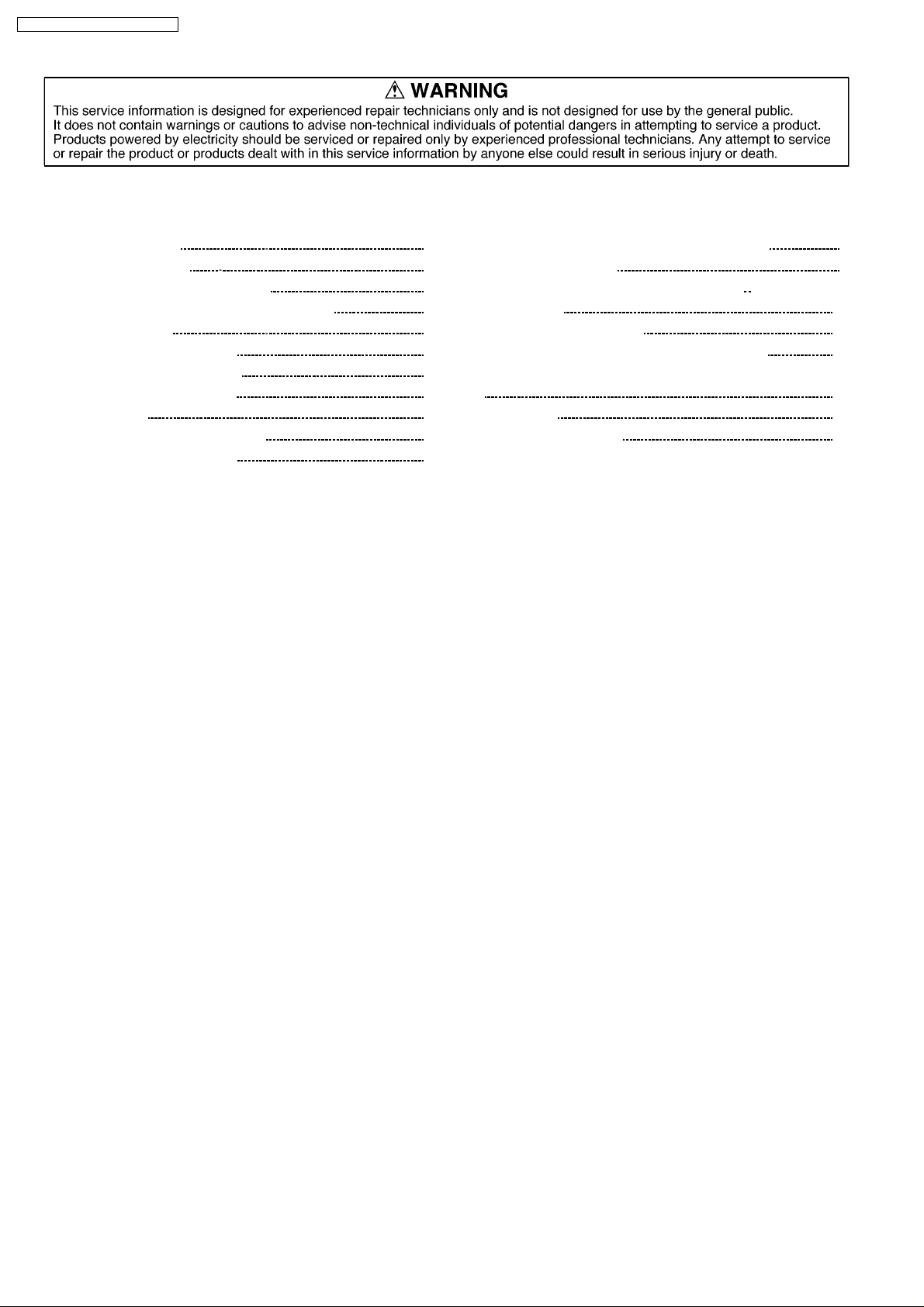
(See Fig. 1)
1. Plug the AC cord directly into the AC outlet. Do not use an
isolation transformer for this check.
2. Connect a 2kΩ, non-inductive resistor and an AC/DC
current meter, in series with each exposed metallic part on
the receiver in turn and an earth such as a water pipe.
3. The current from any point should not exceed 0.7 mA peak
AC or 2mA DC. In the case of a measurement being
outside of the limits specified, there is a possibility of a
29.7
kV. is present when this receiver
ΩΩΩΩ
. When the exposed metal does not have a
shock hazard, and the receiver should be repaired and
rechecked before it is returned to the customer.
Fig. 1 Hot-Check Circuit
1.4. X-Radiation
Warning :
The potential sources of X-Radiation in TV sets are the EHT
section and the picture tube.
When using a picture tube test rig for service, ensure that the
rig is capable of handling 29.7 kV without causing X-Radiation.
Note:
It is important to use an accurate periodically calibrated
high voltage meter.
1. Set the brightness to minimum.
2. Use the remocon to get into SERVICE mode. (Refer to Pg.
6)
3. Measure the EHT. The meter reading should indicate
(+1.2, -1.5) kV
immediate service and correction is required to prevent the
possibility of premature component failure.
4. To prevent the possibility of X-Radiation, it is essential to
use the specified picture tube, if service replacement
becomes necessary.
. If the meter indication is out of tolerance,
1.5. Shut Down Circuit Test
This test must be made as a final check before the set is
4
returned to the customer.
1. Operate the TV set.
2. Set Controls:
Screen (on FBT) ..... minimum
Contrast................... minimu m
Colour........................ minimum
3. Connect a DC voltmeter to cathode of D591, and confirm
that the voltage reading is 24.1 V or less.
4. Supply 25.3 V DC to cathode of D591 and confirm that the
shut down circuit does not operate.
5. Supply 27.94 V DC to cathode of D591 and confirm that the
shut down circuit operates.
6. Switch the set off and disconnect the DC supply. Switch the
set on and Normalize the contrast and colour.
28.5
3
Page 4
TC-21L100R / TC-21W2 / TX-21W2T
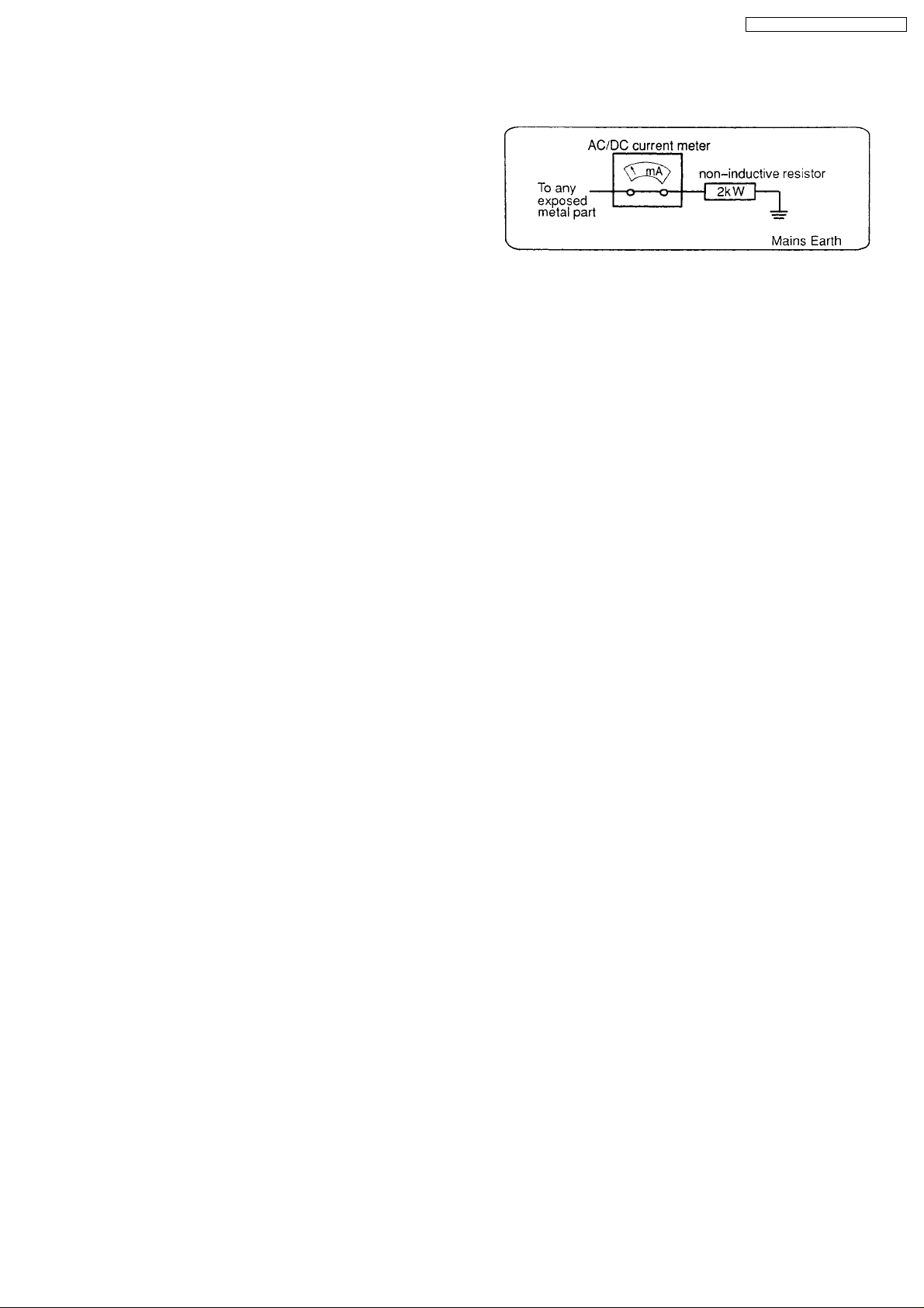
2 MX-5 Chassis Block Diagram
2.1. The I2C Bus Concept :
A. Features
2
1. The I
2. It allows bi-directional data transfer between ICs.
3. It consists of a master and one or more slave ICs.
C bus is a 2-wire serial bus consisting of a clock line (SCL) and a data line (SDA).
- The master initiates transfer and generates clock signals.
- The slave is the IC addressed by a master. It allows bi-directional data transfer between ICs.
3 Service Hints
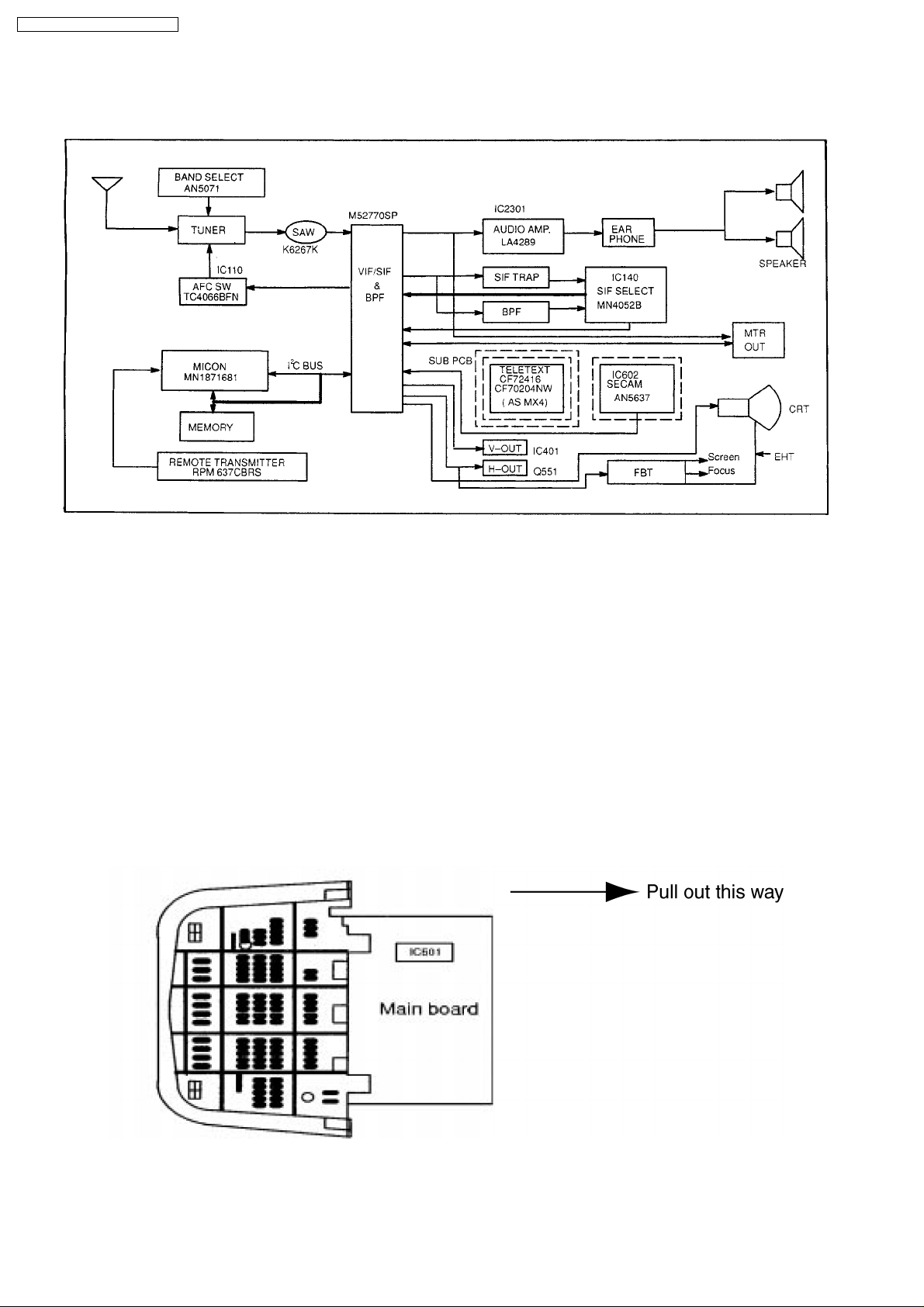
3.1. Service Position for E-Board
1. Remove the back cover.
2. Stand the TV set as shown in fig. 7.
3. Remov e the E-Board from the TV set by pulling the main board out as shown in fig. 7.
Fig. 7
4
Page 5
TC-21L100R / TC-21W2 / TX-21W2T
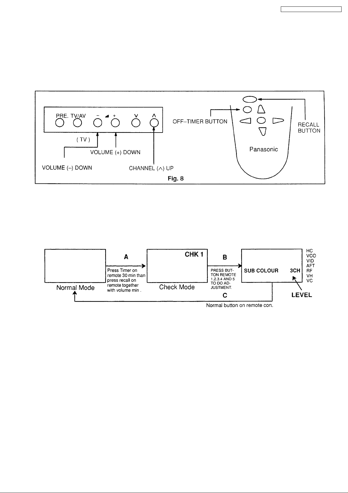
3.2. Purpose of Hotel Mode
To limit the level of main functions of TV such as Volume, Brightness, Tone, Sharpness, Colour and Contrast for hotel use.
How to Set To set the hotel mode, press VOLUME 15 DAC on the TV and TIMER SETTING 30
MIN on the remote control and press channel up on the TV and press recall on the
remote control in the same time simultaneously as shown in figure 8.
How to Cancel To cancel the hotel mode, press VOLUME (-) DOWN on the TV and OFF-TIMER on the
remote control simultaneously as shown in figure 8.
3.3. How to set the Factory Mode for adjustment
Follow the steps shown in the block diagram below to set the Factory Mode for sub-colour; sub-bright, sub-contrast; RGB low-light
and RGB high-light adjustments and return to Normal mode after adjustment.
When the IC601 (VCJ) or IC1104 are replaced, these adjustments must be done as below.
3.3.1. The Sub Adjustment mode
Fig. 9
A: Press the Timer button setting 30 min then press Recall button together with volume
down. Vol must be “0” dac.
The TV in the Normal mode change to check mode. “CHK” will appear on the screen as
shown in Fig. 9.
B: Press button Remote 1,2,3,4 and 5 to select the required adjustment to be adjusted as
shown in Fig. 9.
Press the Volume “up” or “down” button to change the level.
C: Press the Normal button on the remote control transmitter twice to return to Normal
mode.
5
Page 6
TC-21L100R / TC-21W2 / TX-21W2T
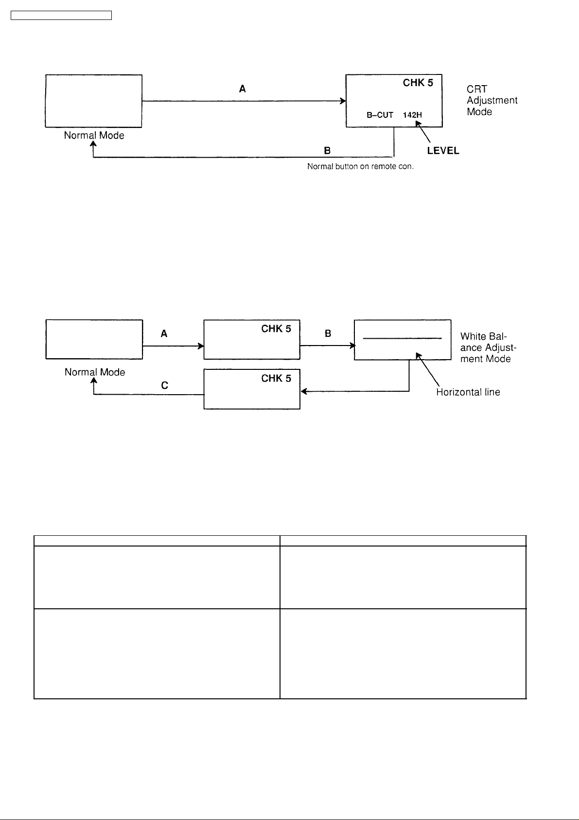
3.3.2. The CRT Adjustment mode
Fig. 9a
A: Press the Timer button setting 30 min then press Recall button together with volume
down. Then press button remote to select “CHK 5”. The TV in the Normal mode
changes to the CRT Adjust ment mode.
Press the remote button volume up or down to select the required adjustment as shown
in Fig. 9a.
(Please refer to procedure on page 11)
B: Press the Normal button on the remote control transmitter twice to return to Normal
mode.
3.3.3. The White Balance Adjustment mode.
Fig. 9b
A: Press the Timer button setting 30 min then press Recall button together with volume
down.
B: Then press the remote button number 5 to enter White Balance Adjustment mode.
(Please refer to procedure on page 11). Press the Volume button to change the level.
C: Press the Normal button on the remote control twice to return to Normal mode or press
on/off button.
4 Adjustment Procedure
Item / Preparation Adjustment Procedure
B Voltage
1. Operate the TV set.
2. Set control as follows:
Brightness.............minimum
Contrast.................minimum
RF AGC
1. Workshop
a. Receive a colour bar signal at an RF level of 61±2dB with 75Ω
loaded.
b. Connect an oscilloscope to TPE 23, set to DC mode.
2. B Field
a. Receive the television broadcast channel known to have the
weakest RF signal strength.
Confirm the DC voltages at the indicated test points are as follows:
FBT PIN 9 : 90.0 ± 2.0V
IC851 PIN 3 : 9 ± 1.0V
IC852 PIN 3 : 5 ± 0.5V
E33-1 : 190.0 ± 15V
D580 Cathode : 22.0 ± 2.0V
D580 Cathode : 46.0 ± 2.5V
1. Select “RF” indication on screen by using remote control at factory
mode.
2. Set RF AGC using remote control volume (+) or volume (-) button
until voltage at TPE 23 starts decreasing or until less than 0.2V
from max.
3. Increase RF signal strength by 2dB, confirm that TPE 23 voltage
drops more than 1V.
6
Page 7
TC-21L100R / TC-21W2 / TX-21W2T
High Voltage
1. Operate the TV set.
2. Set control as follows:
Brightness.............minimum
Contrast.................minimum
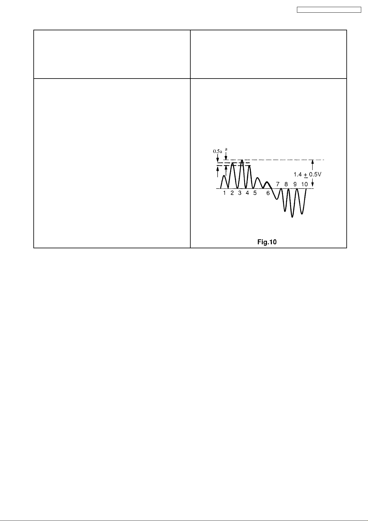
M-NTSC Sub-Tint Adjustment
Apply NTSC rainbow pattern.
Connect an oscilloscope to TPE28.
Connect a short jumper between TPE3 and TPE10.
Press S1107 (FUNC.) and set System to NTSC 4.43
Colour.....................NORMAL or CENTRE
Brightness...............NORMAL or CENTRE
Contrast..................NORMAL or MAX.
Tint.........................NORMAL or CENTRE Press RECALL button on
remote control, then press S1110 (VOL. DOWN) to Sub-Tint. Confirm
CHK display on screen.
1. Connect a DC voltage meter to Pin 1 of IC801 and confirm the
voltage is 90.0 ± 2.0V.
2. Connect a high voltage meter to anode of the picture tube.
3. Confirm that the high voltage is within the range of 24.5 (+ 0.7, -
1.5) kV.
4. Normalize the brightness and contrast.
Confirm the amplitude of waveform : 1.4 ± 0.5V
1. Adjust Sub-Tint so that No. 2,3 and 4 becomes level waveform
similar to Fig. 10.
2. Confirm TPE 28 (R-out) is
1.4 ± 0.5V.
Return to user mode.
3. Confirm phase at Tint is changed more than ±30 by Tint control.
4. Confirm that colour level is maximum when colour DAC is adjusted
to maximum position.
Note: Use Remote control only when adjusting User Control.
7
Page 8
TC-21L100R / TC-21W2 / TX-21W2T
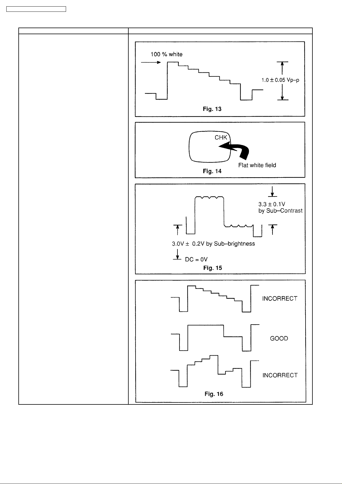
Item / Preparation Waveforms
Video-input, Sub-Contrast, Sub-Brightness and Sub-
Colour
Input a colour bar signal with white at 100% of peak
level. Connection can be made via A/V and this may
enable adjustment of the pattern generator video
output level to obtain the correct black to white
amplitude (at TPE 11)
Confirm that the Sync tip to white amplitude is 1.0±
0.05 Vp-p at Pin 38 (under IC601) as shown in Fig.
13.
Receive a colour bar pattern. Connect an
oscilloscope to pin 3 of E-32 on the E-Board and
chassis earth.
Set Colour, Brightness and Contrast to Normal
(Colour and Brightness at centre, Contrast at max.)
Connect a short jumper between TPE3 and TPE10
(chassis). Note that this step disables the ABL so
avoid operation in this condition for long periods at
high beam current.
Press the RECALL button on remote control together
with volume down button. The screen should then
show a flat whitish field with the OSD message “CHK”
possibly visible at the top as shown in Fig. 14.
Press the Function button (S1107) to select the
required function to be adjusted (in this case
“Contrast”)
Now press either the Volume “up or down” buttons
(S1110 or S1111). “S” and “Contrast” will be
displayed on the screen, indicating “Sub” Contrast,
and the Sub-Contrast level will be changed. Note that
the Volume “up or down” buttons must be pressed
while the Function (i.e. Contrast) OSD is still on
screen.
Press the Function button (S1107) to select
Brightness and then Volume “up or down” buttons
(S1110 or S1111) will similarly permit Sub-Brightness
to be altered and adjusted.
Adjust the Sub-Brightness (first) and Sub-Contrast
(second) to produce the waveform shown in Fig. 15
Using the Function button (S1107) and Volume “up
and down” buttons (S1110 and S1111). Select Subcolour and adjust to produce the waveform shown in
Fig. 16.
Cancel the “CHK” mode by pressing the NORMAL
button on remote control transmitter and remove the
TPE3 to TPE10 jumper.
8
Page 9
Item / Preparation Adjustment Procedure
CRT CUT-OFF
1. Input a flat white Field signal and set
Contrast to maximum.
2. Connect an oscilloscope to TPY 1 (Green
CRT drive) and TPY 2 (Ground). TPY 1
and TPY 2 are located on the Y-PCB
(CRT neck panel).
3. Press “Timer” to setting 30 min then set
vol min. Press button volume - together
with remote button recall to select CRT
ADJUSTMENT Mode (shown in Fig. 9a on
page 8). “CHK” will appear on the screen.
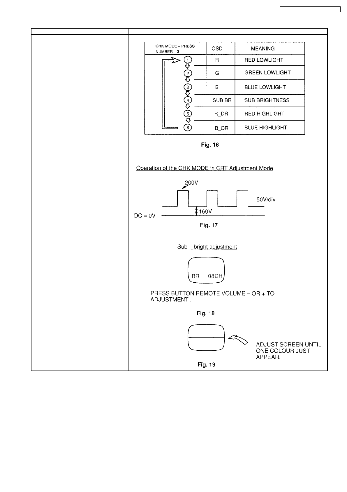
4. Press the remote button number 3 to
select “BR” (meaning “brightness”). Note
that repeated pushing of the Function
button cycles through the CRT adjustment
as shown in Fig. 16.
5. While “BR” is still on screen, set the
screen control to minimum by turning it
anti-clockwise and use the Volume “up” or
“down” remote button to set the DC=0V to
video level at 160V as shown in Fig. 17.
6. Advance the screen control sufficiently to
see the OSD. While “BR” is still on screen,
press number 5 button on the remote
control. This will collapse the vertical scan.
7. Slowly adjust the screen control such that
one of the R, G or B beams just appears
across the centre of the screen. (Fig. 19).
This is the setting point for the screen
control. Note which colour appeared and
do not adjust the low light setting for this
particular colour in the following
procedure.
TC-21L100R / TC-21W2 / TX-21W2T
9
Page 10
TC-21L100R / TC-21W2 / TX-21W2T
Item / Preparation Adjustment Procedure
R, G, B LOW LIGHT ADJUSTMENT
1. Complete steps 1 to 7 of the CRT cut-off
procedure, and do not adjust the screen
control from here on.
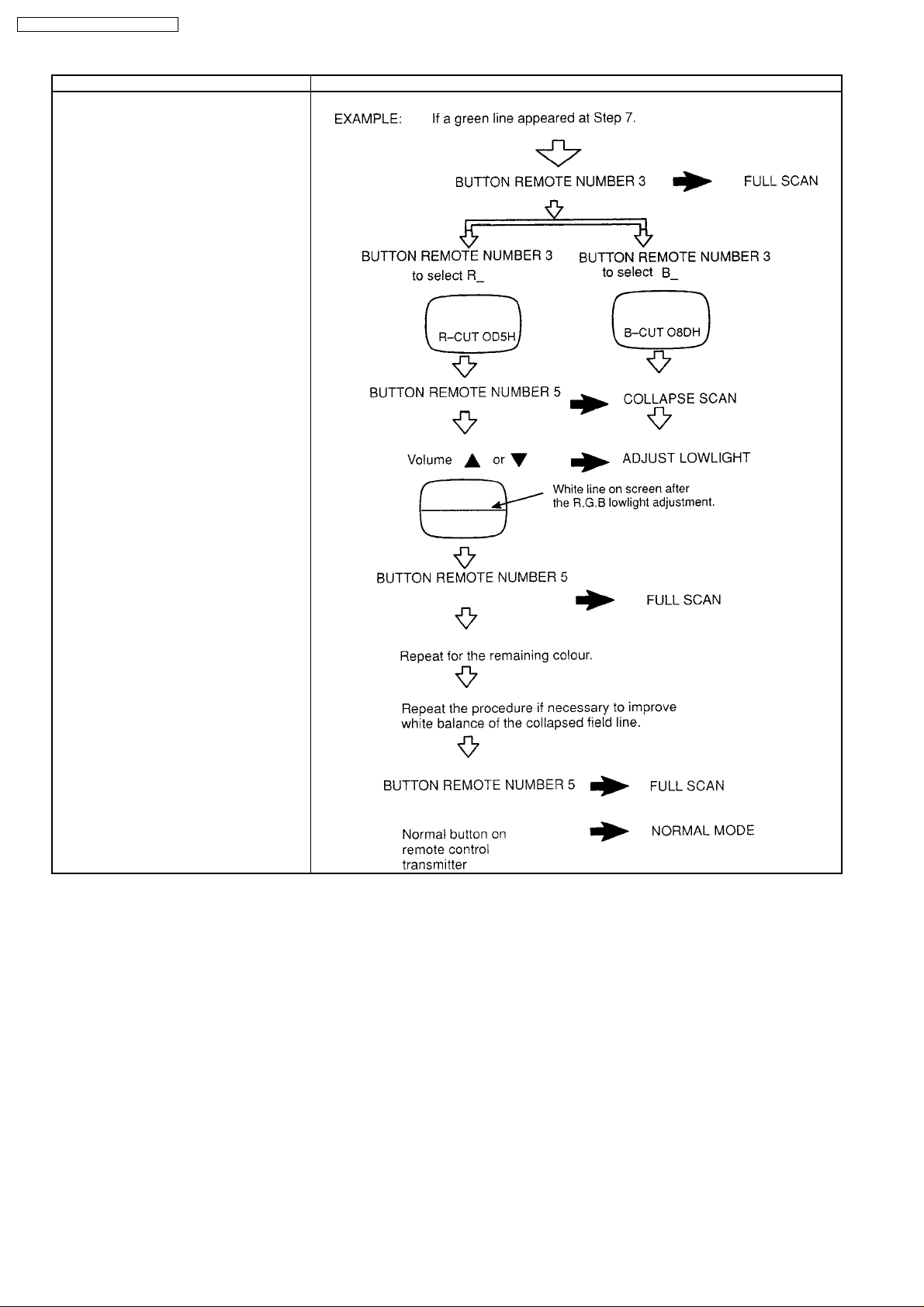
2. Press the remote button number 3 to
return to full field scan, and use the
Remote button to select the lowlight
setting for one of the two colours (R,G or
B) that did not appear at step 7. Fig. 16
shows the selection sequence of the
Function Switch (S1107)
3. With the R_,B_ or G_ OSD still on screen,
press the remote button number 5 again
to collapse the vertical scan.
4. Use the Volume “up” and “down” remote
button to match the levels of the two
colours now on screen.
5. Repeat Steps 9 to 11 for the remaining
colour, to achieve a white line on screen.
6. Press the button number 5 to return to full
frame scan.
R, B HIGH LIGHT ADJUSTMENT
1. Press the Normal Button on the remote
control transmitter twice to return to
Normal Mode, after completing the
preceding CRT cut-off and lowlight
adjustments.
2. Set Contrast to Normal (max) and
continue using the flast white field input as
per Step 1.
3. Press the timer button setting 30 min then
press Volume down button and recall
together. Then press button number 5.
4. Use the Button number 3 to select R (red
highlight) and B (blue highlight) as
necessary (refer to Fig 16).
-
5. With R
or B-still on screen, press the
Volume button “up” and “down” as
necessary to achieve a uniform white field.
6. Press the Normal Button on the remote
control transmitter twice to return to
Normal Mode.
7. Input a greyscale pattern and confirm
correct lowlight and highlight white
balance.
10
Page 11
Before Colour Purity, Convergence and White Balance adjustments are attempted
V. Height, H. Centre and Focus adjustments must be completed.
TC-21L100R / TC-21W2 / TX-21W2T
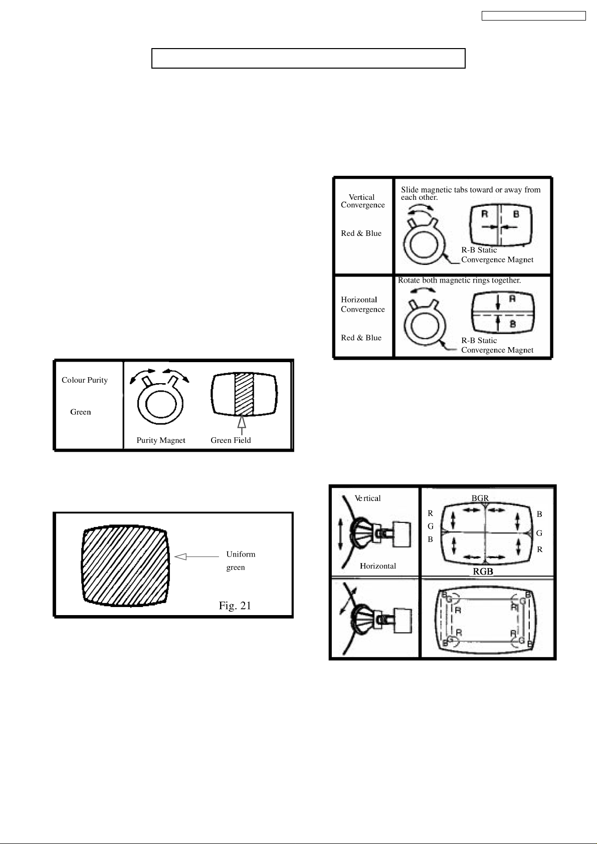
Colour Purity
1. Set the Brightness and Contrast controls to their maximum
positions.
2. Operate the TV set for 30 minutes.
3. Fully degauss the picture tube by using an external
degaussing coil.
4. Apply a crosshatch pattern signal and adjust the static
convergence magnets to the approximately correct position.
5. Receive a black and white signal.
6. Set the controls as follows:
Red...........................maximum
Green.......................maximum
Blue.............................minimum
Press the SHIPPING button on the remote control twice to
select CRT Adjustment Mode and then the Function button
(S1107) as per Fig. 16 to select low lights.
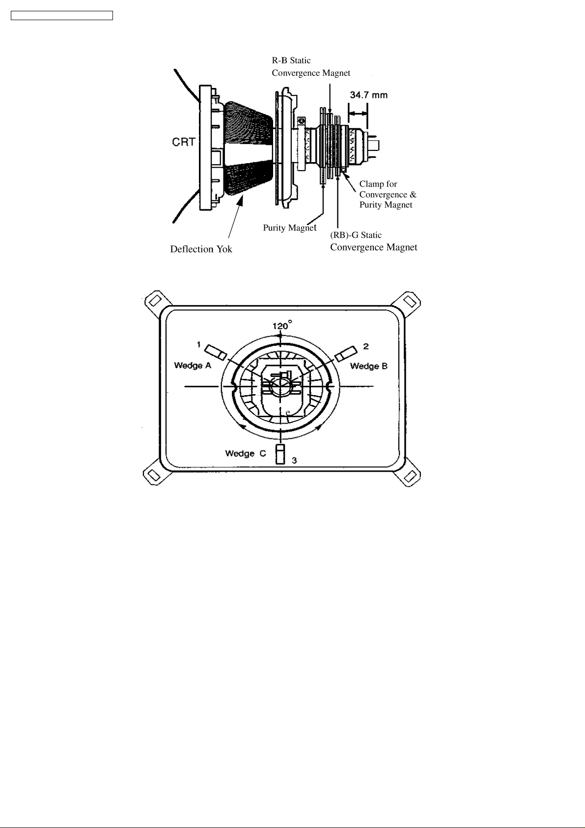
7. Loosen the clamp screw for the deflection yoke A in Fig. 24
and move the deflection yoke as close to the purity magnet
as possible.
8. Adjust the purity magnetic rings so that a vertical green field
is obtained at the centre of the screen.
Convergence
1. Apply a crosshatch pattern signal and Normalize Contrast
control to the maximum position.
2. Adjust Brightness until the grey portion of the crosshatch
pattern just becomes black.
3. Adjust the Red and Blue line at the centre of the screen by
rotating the R-B static convergence magnetic rings.
Fig. 20
9. Slowly push the deflection yoke and set it where a uniform
green field is obtained.
10. Re-adjust the Low Light controls to their correct settings
and make sure that a uniform white field is obtained.
11. Tighten the clamp screw A in Fig. 24.
Fig. 22
4. Adjust Red and Blue with the Green line at centre of the
screen by rotating (RB) -G static convergence magnetic
rings.
5. Lock convergence magnets with silicone sealer.
6. Remove the DY wedges and slightly tilt the deflection yoke
vertically and horizontally to obtain the good overall
convergence.
Fig. 23
7. Fix the deflection yoke by re-inserting the DYwedges. Refer
to Fig. 24.
8. If purity error is found, repeat “Colour Purity” adjustment.
11
Page 12
TC-21L100R / TC-21W2 / TX-21W2T
Fig. 24
Notes:
1. Wedge A, B and C should be inserted following the
sequence of 1, 2 and 3 shown in Fig. 25.
2. The wedges should be set 120° apart from each other.
3. Be certain that the four wedges are firmly fixed and the
Deflection Yoke is tightly clamped in place. Otherwise the
Deflection Yoke may shift its position and cause a loss of
convergence and purity.
Fig. 25
12
Page 13
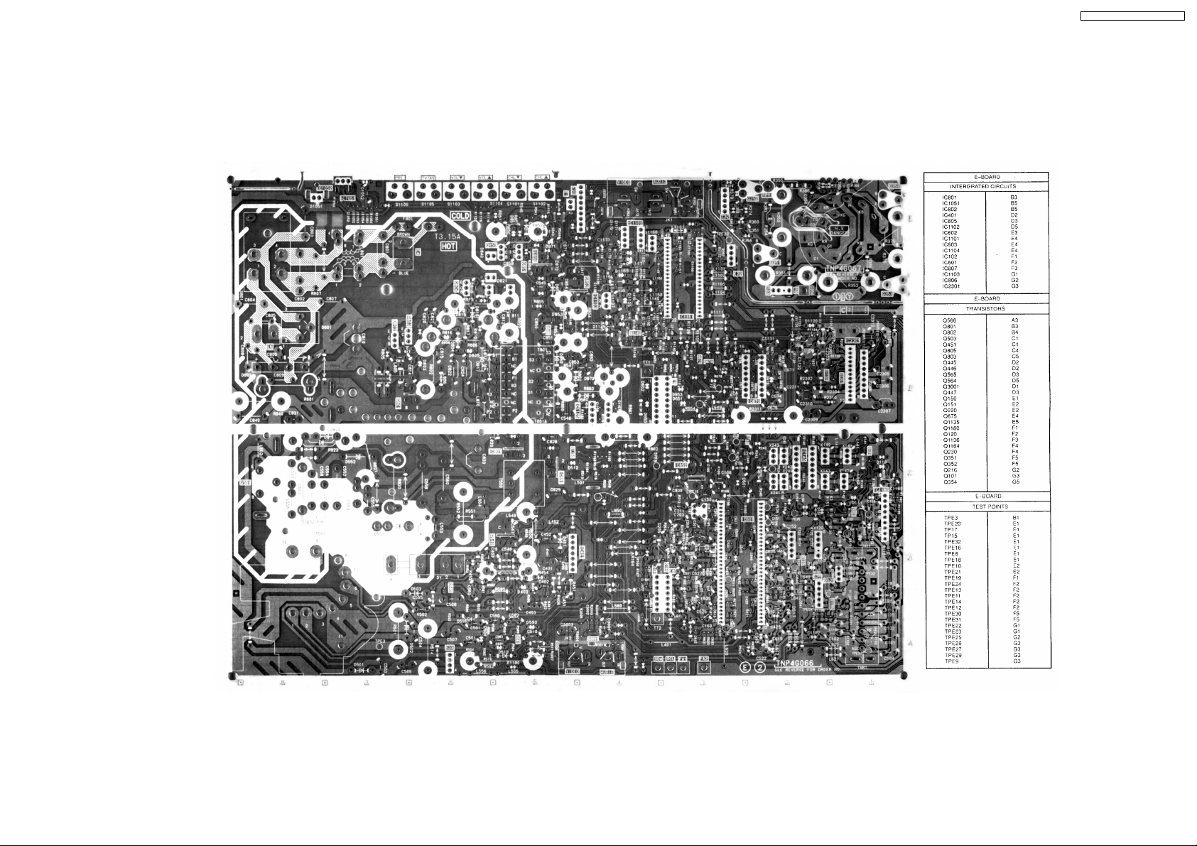
5 CONDUCTOR VIEWS
E-BOARD TNP4G066AC
TNP4G066AA
TC-21L100R / TC-21W2 / TX-21W2T
13
Page 14
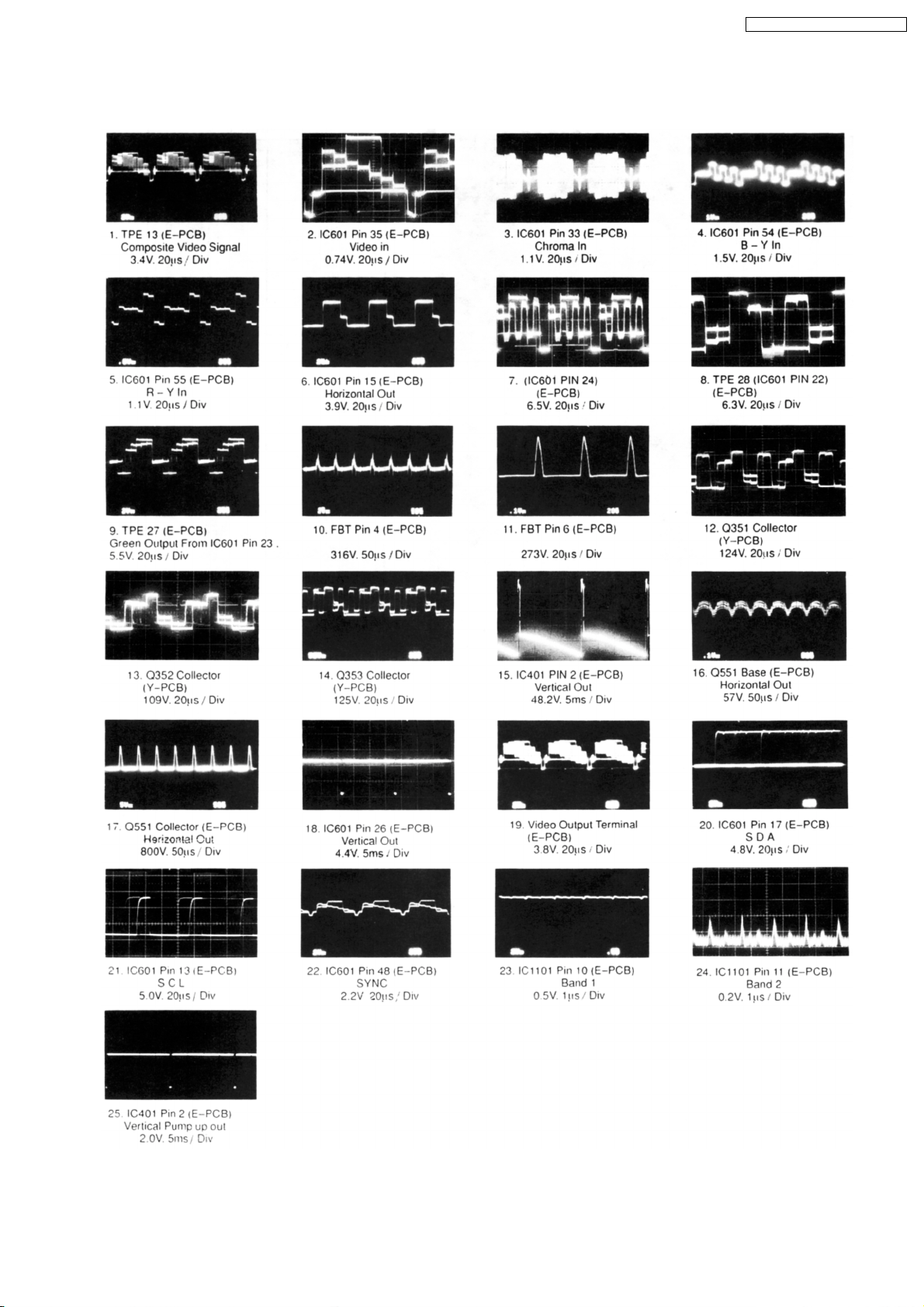
6 TEST POINT WAVEFORMS
TC-21L100R / TC-21W2 / TX-21W2T
15
Page 15

TC-21L100R / TC-21W2 / TX-21W2T
7 BLOCK DIAGRAM FOR INTEGRATED CIRCUITS
16
Page 16

TC-21L100R / TC-21W2 / TX-21W2T
8 Schematic Diagram for models TC-15PM10R (MX-7
Chassis)
IMPORTANT SAFETY NOTICE Components identified by
mark have special characteristics important for safety.
When replacing any of these components, use only
manufacturer’s specified parts.
Notes:
1. Resistor
All resistors are carbon 1.4W resistors unless marked as follows:
Unit of resistance is OHM (Ω) (K=1 000 M=1 000 000)
Nonflammable Metal Oxide
Solid Metal Film
Wire Wound Fuse
2. Capacitor
All capacitors are ceramic 50V capacitors unless marked as follows:
Unit of capacitance is µF, unless otherwise noted.
Temperature
Compensation
Polyester Bipolar
Metalized
Polyester
Polypropylene Z-Type
Electrolytic
Dipped
Tantalum
3. Coil
Unit of inductance is µH, unless otherwise noted.
Unit of resistance is OHM (Ω) (K=1 000 M=1 000 000)
4. Test Point
: Test Point position
5. Earth Symbol
: Chassis Earth (Cold) : Line Earth (Hot)
6. Voltage Measurement
Voltage is measured using a DC voltmeter.
Conditions of the measurement are the following:
Power Source..........................AC 220V, 50Hz
Receiving Signal.....................Colour Bar signal (RF)
All customer’s controls............Maximum positions
7. Number in red circle indicates waveform number.
(See waveform pattern table)
8. When arrow mark (
9.
: Indicates the major signal flow.
) is found, connection is easily found from the direction of arrow.
10. This schematic diagram is the latest at the time of printing and subject to change without notice.
Remarks:
1. The Power Circuit contains a circuit area which uses a separate power supply to isolate the earth connection. The circuit is
defined by HOT and COLD indications in the schematic diagram. Take the following precautions:
All circuits except the Power Circuit are cold.
Precautions:
a Do not touch the hot part or the hot and cold parts at the same time or you may be
shocked
b Do not short-circuit the hot and cold circuits or a fuse may blow and parts may break
c Do not connect an instrument such as an oscilloscope to the hot and cold circuits
simultaneously or a fuse may blow. Connect the earth of instruments to the earth
connection of the circuit being measured.
d Make sure to disconnect the power plug before removing the chassis.
17
Page 17

TC-21L100R / TC-21W2 / TX-21W2T
KEY NO. FUNCTION DATA CODE KEY NO. FUNCTION DATA CODE
1 POWER 3D 16 MAIN MENU 52
2 MUTE 32 17 PIC MENU 50
3 TV/AV 05 18 NORMALIZE 0C
4 RECALL 39 19 TIMER 0F
5 DOUBLE DIGIT 3B 20 CH UP 34
6 CH 0 19 21 CH DOWN 35
7 CH 1 10 22 VOL + 20
8 CH 2 11 23 VOL - 21
9 CH 3 12 24 CURSOR UP 4A
10 CH 4 13 25 CURSOR DOWN 4B
11 CH 5 14 26 CURSOR LEFT 4E
12 CH 6 15 27 CURSOR RIGHT 4F
13 CH 7 16
14 CH 8 17
15 CH 9 18
18
Page 18

TC-21L100R / TC-21W2 / TX-21W2T
KEY NO. FUNCTION DATA CODE KEY NO. FUNCTION DATA CODE
1 MAIN MENU 52 21 CH 3 12
2 - - 22 CH 6 15
3 CURSOR UP 4A 23 CH 9 18
4 NORMALIZE 0C 24 DOUBLE DIGIT 3B
5 POWER 3D 25 CURSOR RIGHT 4F
6 MUTE 32 26 HOLD 09
7 TIMER 0F 27 DISPLAY CANCEL 04
8 TV/AV 05 28 CYAN 73
9 CURSOR LEFT 4E 29 CH UP 34
10 F/T/B 0C 30 CH DOWN 35
11 TIME/TEXT 0B 31 VOL UP 20
12 GREEN 71 32 VOL DOWN 21
13 CH 2 11 33 PIC MENU 50
14 CH 5 14 34 TV/AV 03
15 CH 8 17 35 INDEX 08
16 CH 0 19 36 RED 70
17 - - 37 CH 1 10
18 CURSOR DOWN 4B 38 CH 4 13
19 REVEAL 1C 39 CH 7 16
20 YELLOW 72 40 RECALL 39
19
Page 19

Page 20

Page 21

Page 22

Page 23

Page 24

Page 25

Page 26

Page 27

Page 28

Page 29

Page 30

10 Replacement Parts List
TC-21L100R / TC-21W2 / TX-21W2T
Components identified by!mark have special characteristics important for safety. When
Note: Printed circuit board assembly with “NLA” is no longer available after production
discontinuation of the complete set.
Abbreviation of part name and description
1. Resistor
Example:
ERD25TJ104 C 100KΩ, J, 1/4W
Type Allowance
Type Allowance
C: Carbon
F: Fuse
M: Metal Oxide
Metal Film
S: Solid
W: Wire Wound
Important Safety Notice
replacing any of these components, use manufacturer’s specified parts.
2. Capacitor
Example:
ECKF1H103ZF C 0.01UF, Z, 50V
Type Allowance
Type Allowance
F: ±1%
G: ±2%
J: ±5%
K: ±10%
M: ±20%
C: Carbon
E: Electrolytic
P: Polyester
Polypropylene
T: Tantalum
C: ±0.25pF
D: ±0.5pF
F: ±1pF
G: ±3%
J: ±5%
K: ±10%
L: ±15%
M: ±20%
P: +100% -0%
Z: +80% -20%
27
Page 31

TC-21L100R / TC-21W2 / TX-21W2T
Replacement Parts List (FOR TC-21L100R/TC-21W2 page 22 to 29)
28
Page 32

TC-21L100R / TC-21W2 / TX-21W2T
29
Page 33

TC-21L100R / TC-21W2 / TX-21W2T
30
Page 34

TC-21L100R / TC-21W2 / TX-21W2T
31
Page 35

TC-21L100R / TC-21W2 / TX-21W2T
32
Page 36

TC-21L100R / TC-21W2 / TX-21W2T
33
Page 37

TC-21L100R / TC-21W2 / TX-21W2T
34
Page 38

TC-21L100R / TC-21W2 / TX-21W2T
35
Page 39

TC-21L100R / TC-21W2 / TX-21W2T
Replacement Parts List
36
Page 40

TC-21L100R / TC-21W2 / TX-21W2T
37
Page 41

TC-21L100R / TC-21W2 / TX-21W2T
38
Page 42

TC-21L100R / TC-21W2 / TX-21W2T
39
Page 43

TC-21L100R / TC-21W2 / TX-21W2T
40
Page 44

TC-21L100R / TC-21W2 / TX-21W2T
41
Page 45

TC-21L100R / TC-21W2 / TX-21W2T
42
Page 46

TC-21L100R / TC-21W2 / TX-21W2T
43
Printed in Malaysia
97070600
 Loading...