

Panasonic TC-21FG20P Schematic
Colour Television
TC-21FG20P
GP31 Chassis
ORDER NO. MTV0501396C3
Specifications
Power Source : AC AUTO 110-240V, 50/60 Hz
Power Consumption : 83W
Aerial Impedance : 75Ω unbalanced
Coaxial type
Receiving Channels :
VHF 2-13 (USA STANDARD)
CATV 1-125 (USA STANDARD)
UHF 14-69 (USA STANDARD)
Intermediate Frequency :
Video 38.0 MHz
Sound 31.5 MHz (D, K, K1)
32 MHz (I)
32.5 MHz (B, G)
33.5 MHz (M)
Colour 33.57 MHz (PAL)
33.6 MHz (SECAM)
33.75 MHz (SECAM)
34.42 MHz (NTSC)
Video / Terminals : AV1, 2
RAV In Video In 1 Vp-p 75Ω
Audio In Approx. 400mVrms
Monitor Out Video Out 1 Vp-p 75Ω
Audio Out Approx. 400mVrms
High Voltage :
at zero beam current
Picture Tube : A51LXR195X
Measured diagonally,
Audio Output : 16.0W
Dimensions : Height:473mm
Mass : 24 kg (Net Wt.)
Specifications are subject to change without notice.
Mass and dimensions shown are approximate.
27.5kV±1.5
51cm (21 inches)
90° deflection
Width : 648 mm
Depth : 488 mm
© 2005 Matsushita Electric Industrial Co., Ltd. All
rights reserved. Unauthorized copying and
distribution is a violation of law.

CONTENTS
Page Page
1 Safety Precautions 3
1.1. General Guide Lines
1.2. Leakage Current Cold Check
1.3. Leakage Current Hot Check (Fig. 1)
1.4. X-Radiation
1.5. GP31 Chassis Block Diagram
2 Service Hints
2.1. Service Position for E-Board
2.2. Factory Mode Adjustment
2.3. Adjustment for White Balance
2.4. Adjustment for CRT CUT OFF
3
3
3
3
4
5
5
5
6
6
2.5. Adjustment Procedure
2.6. PAL Colour
2.7. Adjustment
3 Conductor Views
4 Schematic Diagram
4.1. A Board
4.2. L Board
5 Parts Locations
6 Replacement Parts List
6.1. Replacement Parts List
12
13
15
20
23
24
25
7
8
8
2
1 Safety Precautions
1.1. General Guide Lines
1. It is advisable to insert an isolation transformer in the AC supply before servicing this hot chassis.
2. When servicing, observe the original lead dress, especia lly the lead dress in the high voltage circuits. If a short circuit is found,
replace all parts which have been overheated or damaged by the short circuit.
3. After servicing, see to it that all the protective devices such as insulation barriers, insulation papers, shields and isolation R-C
combinations, are properly installed.
4. When the receiver is not to be used for a long period of time, unplug the power cord from the AC cord outlet.
5. Potential, as high as
involves the danger of a shock hazard from the receiver power supply. Servicing should not be attempted by anyone who is not
thoroughly familiar with the precautions necessary when working on high voltage equipment. Always discharge the anode of the
picture tube to the receiver chassis before handling the tube. After servicing make the following leakage current checks to
prevent the customer from being exposed to shock hazards.
1.2. Leakage Current Cold Check
1. Unplug the AC cord and connect a jumper between the two prongs on the plug.
2. Turn on the receiver’s power switch.
Measure the resistance value, with an ohmmeter, between the jumper AC plug and each exposed metallic cabinet part on the
receiver, such as screw heads, aerials, connectors, control shafts, etc. When the exposed metallic part has a return path to the
chassis, the reading should be between 4 MΩand 20 MΩ. When the exposed metal does not have a return path to the chassis,
the reading must be infinite.
29.0kV
is present when this receiver is in operation. Operation of the receiver without the rear cover
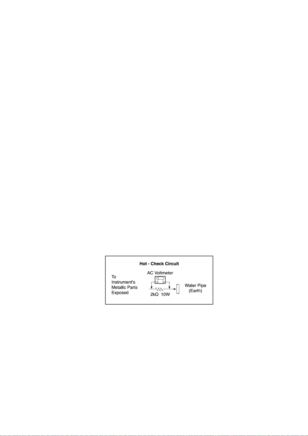
1.3. Leakage Current Hot Check (Fig. 1)
1. Plug the AC cord directly into the AC outlet. Do not use an isolation transformer for this check.
2. Check a 2 kΩnon-inductive resistor and an AC/DC current meter, in series with each exposed metallic part on the receiver in
turn and an earth such as a water pipe.
The current from any point should not exceed 0.7 mA peak AC or 2 mA DC. In the case of a measurement being outside of
these limits specified, there is a possibility of a shock hazard and the receiver should be repaired and rechecked before it is
returned to the customer.
Fig. 1
,
1.4. X-Radiation
Warning:
The potential sources of X-Radiation in TV set are the EHT section and the picture tube. When using a picture tube test jig for
service, ensure that jig is capable of handling
Note:
It is important to use an accurate periodically calibrated high voltage meter.
1. Set the brightness to minimum.
2. Use the remocon to get into Service Mode.
3. Measure the EHT. The meter reading should indicate
and correction is required to prevent the possibility of premature component failure.
4. To prevent the possibility X-Radiation, it is essential to use the specified picture tube, if service replacement becomes
necessary.
29.0kV
without causing X-Radiation.
27.5±1.5kV
. If the meter indication is out of tolerance, immediate service
3
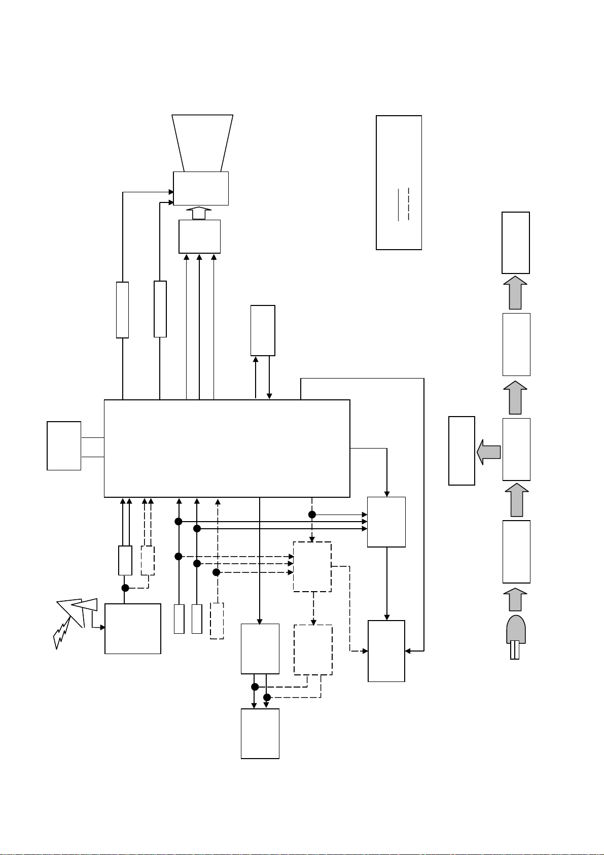
1.5. GP31 Chassis Block Diagram
I
CRT
coil
defl.
B
R
G
MONO
STEREO
SOUND MODULATION
3.3V
IC1201
IC1103
EEPROM
Antenna
V OUT
V
SDA SCL
IF
SAW
TUNER
SIF
SAW
H OUT
H
CVBS2
AV1
AV1
RGB
CVBS3
AV2
AV2
IC601
YUV
YUV1
UOC
AUDIO
TRAP
SOUND
IFVO
CVBS1
AMOUT
AMP
IC2301A
CVBSO
QIF / AUDIO
DEEMP
MSP
IC2101
AMP
IC2301
AUDIO
SW
IC3151
AUDIO
SWITCH
OUT
MONITOR
IC851
5V & 8V
IC880
STBY 5V
T801
IC801
LIFE CCT
PRIMARY
SPEAKER
4
2 Service Hints
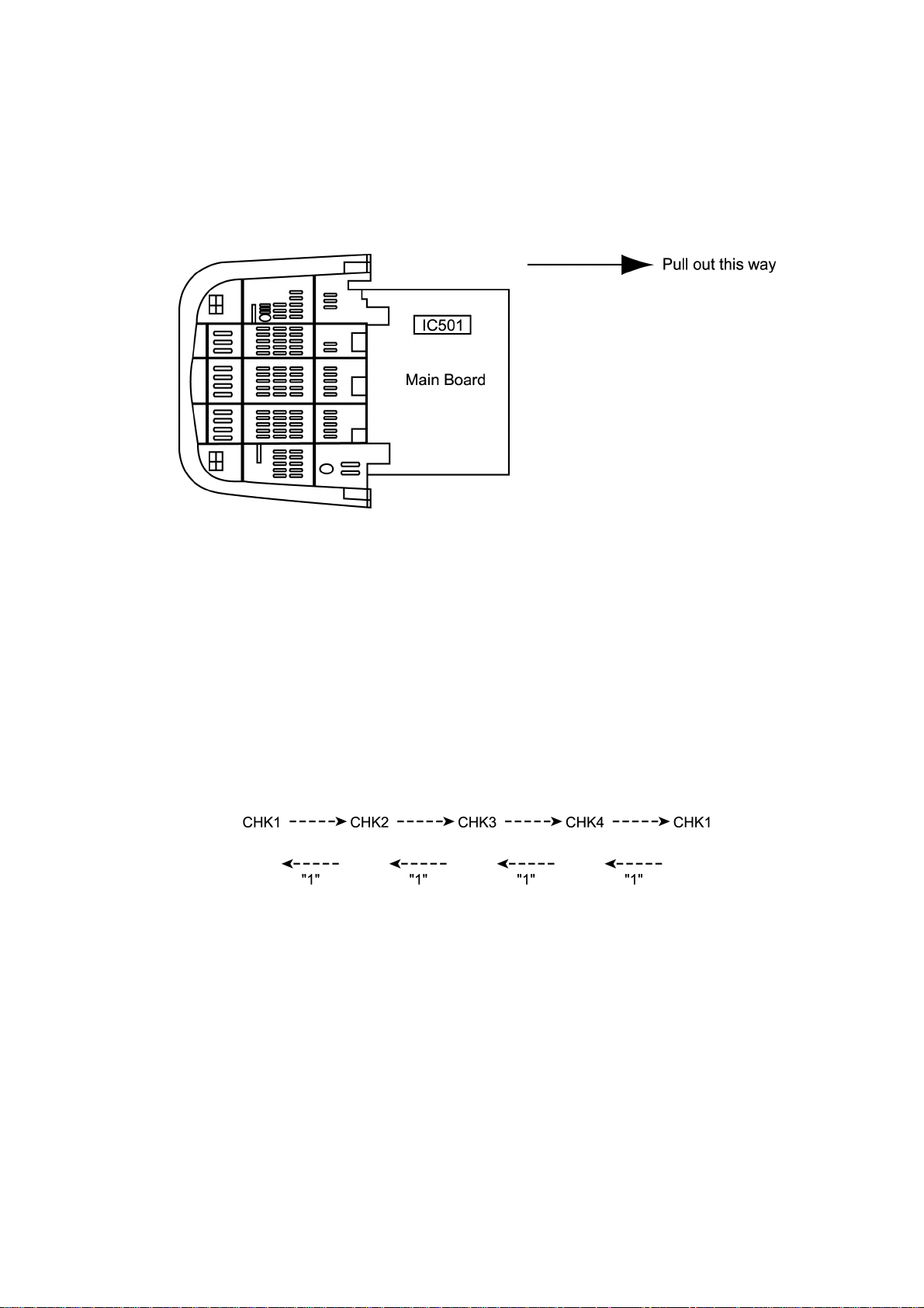
2.1. Service Position for E-Board
1. Remove the back cover.
2. Stand the TV set as shown in Fig. 2.
3. Remove the A-Board from the TV set by pulling the main board out as shown in Figure 2.
Fig. 2
2.2. Factory Mode Adjustment
How to set : To set the Factory mode, press Volume 0 dac on the TV and Timer Setting 30 min. on
the remote control and press Volume (-) Down button on the TV together press recall on
the remote control.
CHK should appear on right of TV screen.
To move from CHK1 to CHK2 mode, etc. please follow below rotation :
To Set Self-Check : Press the Volume Down button on TV then press the Off Timer button on remote
control.
5
2.3. Adjustment for White Balance
Preparation:
1. Receive the white balance pattern and aging should have been performed over 30 minutes.
2. Set the picture menu to DYNAMIC NORMAL.
3. Degausse the CRT face.
4. Fix the CRT colour analyze r receiver unit to CRT face.
Adjustment of Low Light.
1. Adjustment Sub Bright, so that Y = 6.3 ± 1.0 nit.
2. Adjustment R-CUT OFF, so that X = 0.235 ± 0.010 nit.
3. Adjustment G-CUT OFF, so that Y = 0.235 ± 0.010 nit.
Adjustment of High Light
1. Adjustment Sub Bright, so that Y = 270 nit.
2. Adjustment R-Drive, so that X = 0.265 ± 0.010 nit.
3. Adjustment B-Drive, so that Y = 0.265 ± 0.010 nit.
2.4. Adjustment for CRT CUT OFF
Preparation:
1. Connect the oscilloscope probe to TPL5.
2. Screen VR min.
3. Set the data Sub Bright, Bright.
4. In service Mode at “Bright” dac press [5] in factory mode to enter vertical line and adjust by volume down or up button.
5. Adjust “Screen VR” until 1-H Line appears.
6
2.5. Adjustment Procedure
2.5.1. +B Voltage
Item / preparation
1. Operate the TV set.
2. Set control as follows :
Brightness ........... minimum
Contrast ............... minimum
Adjustment procedure
1. Confirm the DC voltage at the indicated test points, as
follows :
TPA 10 : 141.0 ± 1.5V
TPA 8 : 8 ± 1V
TPA 9 : 5 ± 1V
TPA 21 : 175 ± 15V
2.5.2. RF AGC
Item / preparation
1. Receive a colour bar signal at an RF level of 69 ± 1-2 dBU
with 75Ωloaded.
2. Connect digital multimeter to RF AGC at Tuner.
Adjustment procedure
1. Select “RF AGC” indication in CHK2, on Screen by remote
control at factory mode.
2. Set RF AGC by using remote control Volume (+) or Volume
(-) button until voltage AGC at Tuner reaches 2.3 ± 0.1V at
TPA 15 (Tuner point).
3. Increase RF signal strength by 2dB, confirm AGC at Tuner
voltage drop.
2.5.3. High Voltage
Item / preparation
1. Receive the crosshatch pattern.
2. Set to 0 Beam.
Screen VR .......... minimum
Contrast .............. minimum
Adjustment procedure
1. Connect a DC voltage meter to TPA 10 and confirm the +B
voltage is 141.0 ± 1.5V.
2. Connect a high frequency voltmeter to heater and confirm
that voltage reads 6.3 ± 0.24 (VRMS).
3. Normalize the brightness and contrast.
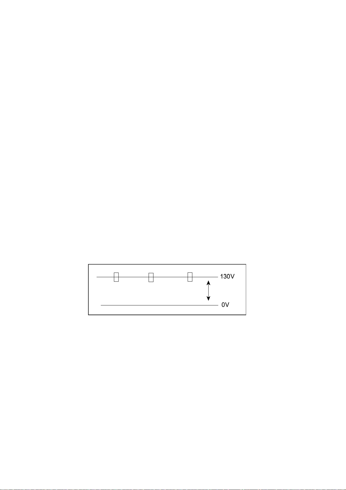
2.5.4. NTSC TINT COLOUR
Item / preparation
1. Connect oscilloscope probe to TPL1 (R OUT) with 10k
series resistor.
2. Press Main Menu and set system to use AV-NTSC (3.58
MHz).
DYNAMIC ................... Normal
Channel CLR Set ..... STD
Adjustment procedure
1. Adjust Sub-Tint so that No. 2, 3 and 4 becomes level
waveform is similar to Fig. 3.
2. Confirm phase at Tint is changes more than ± 15 by Tint
control.
3. Confirm that colour level is maximum when colour DAC is
adjusted to maximum position.
Note:
Use remote control only when adjusting user mode to
Sub-Tint.
Ω
7
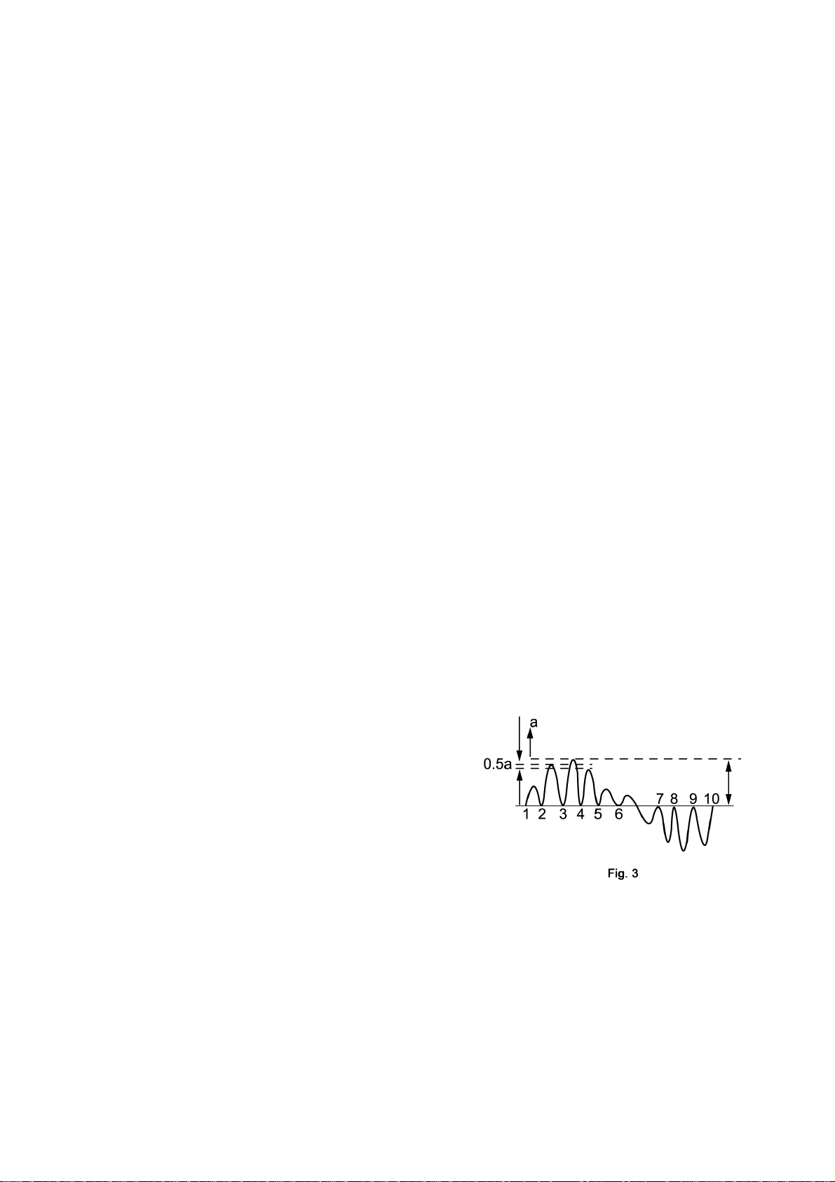
2.6. PAL Colour
1. Receive the PAL B/G studio colour bar pattern and adjust local frequency at the best tuned position.
2. Pic Menu: Dynamic Normal, Confirm Contrast - 100 DAC, Sub Contrast - 21 dac.
3. Channel colour set --------- STD
4. “CHK2” and press digit key “5” (AKB OFF) also confirm OSD become blue colour.
5. Set (A) to 2.1 ± 0.1V by BRT (CHK2) at measurement point TPL 2 Fig. 4.
2.7. Adjustment
1. Connect oscilloscope probe to TPL 2 (G OUT) with 10kΩseries resistor and adjust Contrast so that (B) as in Fig. 4 is 2.4 ±
0.05V.
2. Adjust “Sub Colour” so that waveform as in Fig. 4 (1) 2.5 ± 0.1V.
3. Connect oscilloscope probe to TPL 1 (R OUT) with 10kΩseries resistor and confirm waveform as in Fig. 5 is (2) 2.7 ± 0.4V.
4. Press digit key “5” (AKB ON) and confirm the OSD become white colour.
8
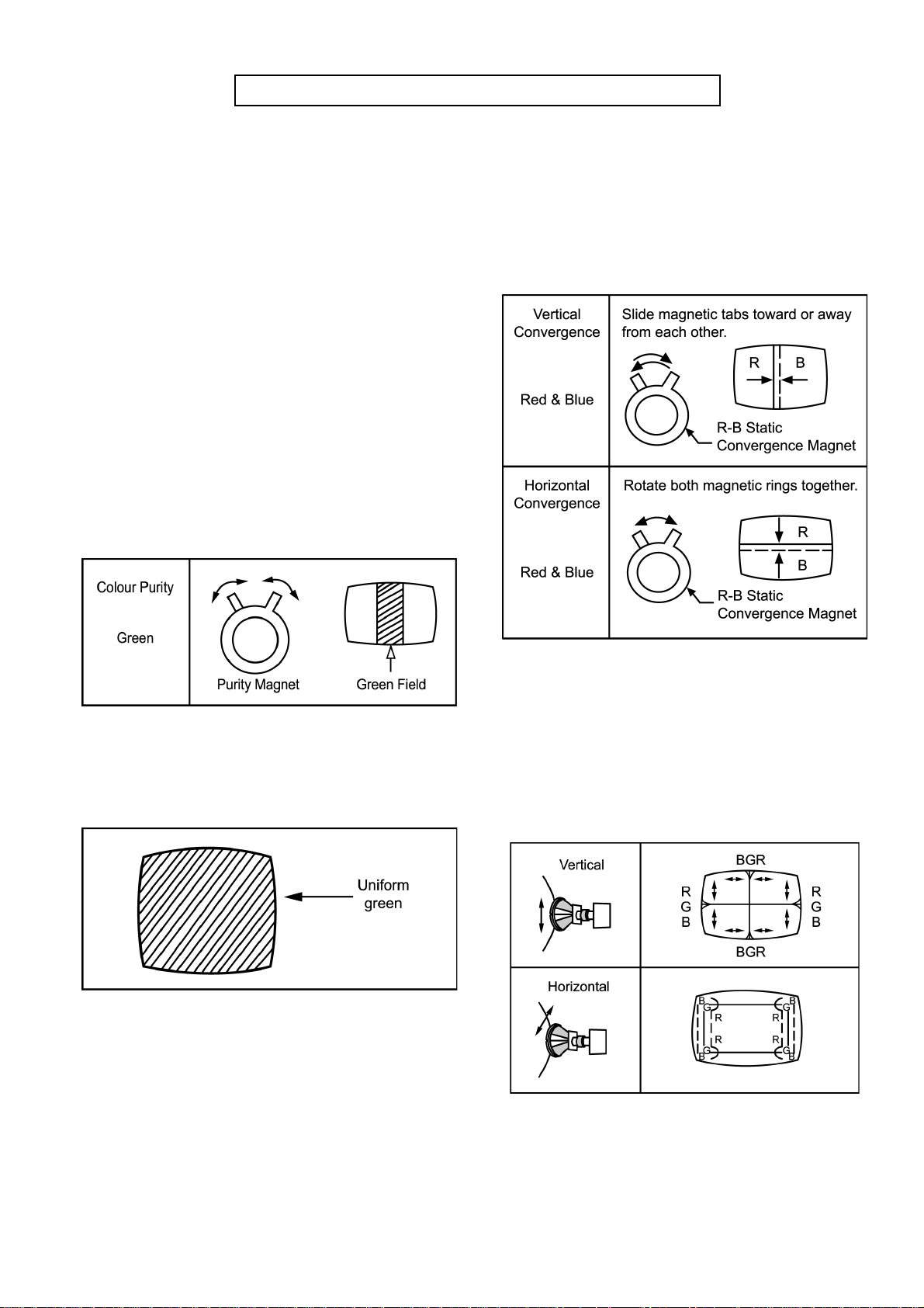
Before Colour Purity, Convergence and White Balance adjustment are attempted,
V. Height, H. Centre and Focus adjustments must be completed.
Colour Purity
1. Set the Brightness and Contrast controls to their maximum
positions.
2. Operate the TV set for 60 minutes.
3. Fully degausse the picture tube by using an external
degaussing coil.
4. Apply a crosshatch pattern signal and adjust the static
convergence magnets to the approximately correct position.
5. Receive a black and white signal.
6. Set the control as follows:
Red................minimum
Green.............minimum
Blue...............minimum
Press the Shipping button on the remote control twice to
select CRT Adjustment Mode to select low light.
7. Loosen the clamp screw for the Deflection Yoke A in Fig. 10
and move the Deflection Yoke as close to the purity magnet
as possible.
8. Adjust the purity magnetic rings so that a vertical green field
is obtained at the centre of the screen.
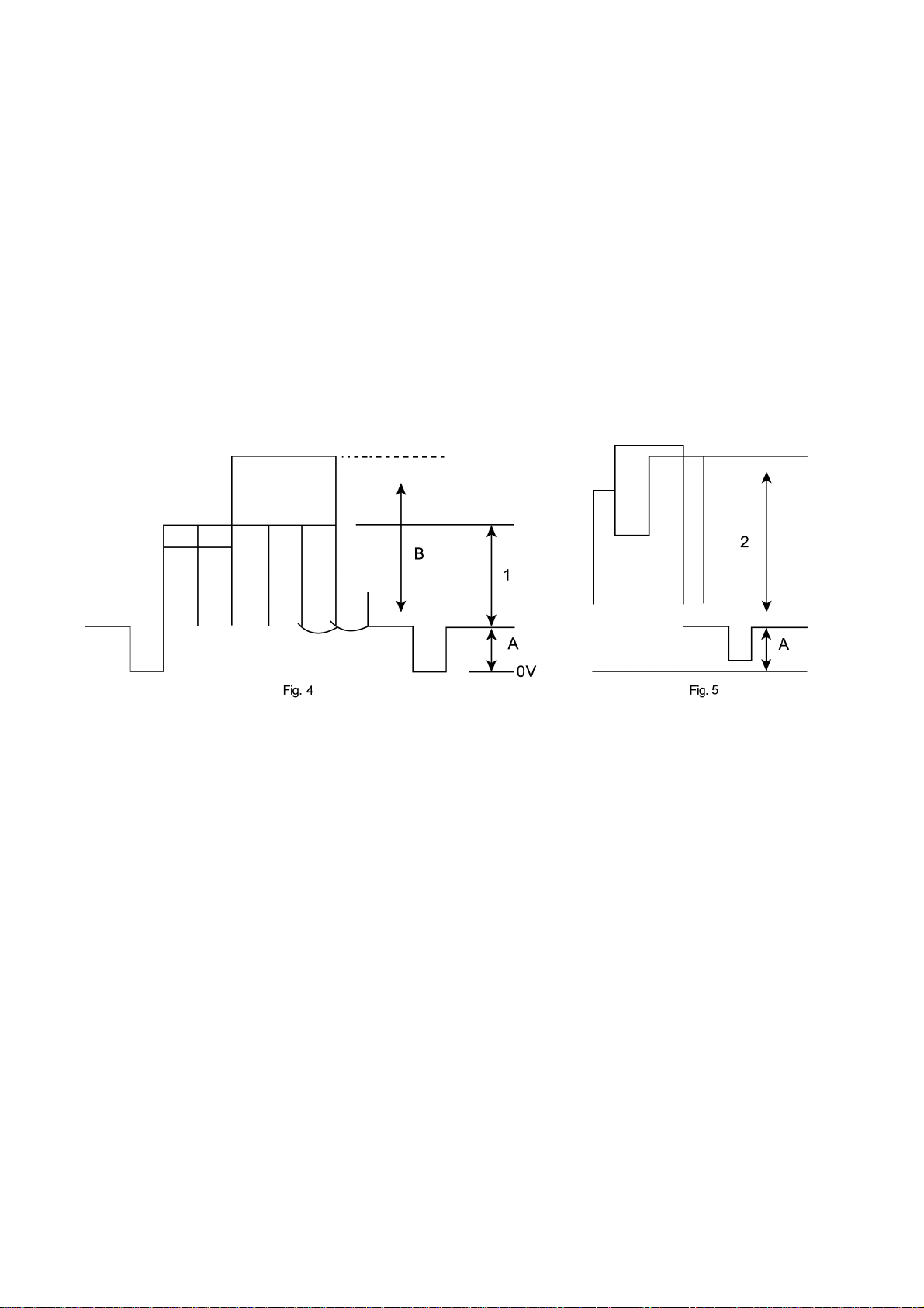
Convergence
1. Apply a crosshatch pattern signal and Normalize Contrast
control to the maximum position s.
2. Adjust Brightness until the grey position of the crosshatch
pattern just becomes black.
3. Adjust the Red and Blue line at the centre of the screen by
rotating the R-B static.
Fig. 6
9. Slowly push the Deflection Yoke and set it where a uniform
green field is obtained.
Fig. 21
10. Re-adjust the Low Light controls to their correct settings
and make sure that a uniform white field is obtained.
11. Tighten the clamp screw A in Fig. 10.
Fig. 8
4. Adjust Red and Blue with Green line at centre of the screen
by rotating (RB)-G static convergence magnetic rings.
5. Lock convergence magnets with silicone sealer.
6. Remove the DY wedges and slightly tilt the Deflection Yoke
vertically and horizontally to obtain the good overall
convergence.
Fig. 9
7. Fix the Deflection Yoke by reinserting the DY wedges. Refer
to Fig. 10.
8. If purity error is found, repeat “Colour Purity” adjustment.
9
 Loading...