

Page 1
Model
Name
Model
No.
Switch-M48eG
Product Specification
PN28480K-MY
401-28480K-MY-SP02
Page 1 of 10
1. Summary
Switch-M48eG is an all Giga bit Ethernet switching hub equipped with eight 10BASE-T/100BASE-TX/1000BASE-T ports
and one SFP extension slot with a management function.
2. Feature
(1) Has wire-speed Layer 2 Switching function.
(2) Has a loop detection function, which notifies when a loop occurs with the corresponding port LED and automatically
shuts down the looped port.
In addition, when a port is shut down and when it automatically recovers, an SNMP trap can be sent to notify the administrator.
(3) Has a loop detection history function, which notifies when a loop occurs with the corresponding LED and enables a network
administrator to identify the looped port after the loop is removed.
(4) Embedded power saving mode detects the connection status automatically and saves power consumption to minimum.
(5) Use of LED indicator switching button saves power consumption of LED lamps.
(6) Ports 1 to 48 are auto negotiation-ready 10/100/1000BASE-T ports. Their speed and communication mode can be changed
by configuration.
Ports 45-48 can be used as a 10/100/1000BASE-T port corresponding to auto negotiation or an SFP extension slot exclusively.
(7) All twisted pair ports support straight/cross cable auto sensing function.
Simply connect devices with straight cables, whether it is a terminal or a network device.
(This function does not work if the port communication configuration is set at Fixed or Link Aggregation.
Ports 1 to 44 are set at MDI-X. (default))
(8) VLAN function allows free grouping of up to 256 VLANs.
(9) The IEEE802.1p compatible QoS function is supported.
(10) Has an Internet Mansion function, which ensures security between each door.
(11) Has a port grouping function, which groups ports that are allowed to communicate with one another to limit communications
between different groups.
(12) Equipped with energy efficient Ethernet (EEE) conforming to IEEE802.3az (LPI).
When there is no data transmission at link up, the energy-saving state automatically starts so that power consumption
can be reduced on each port.
(13) The IEEE802.1X compatible user authentication function (EAP-MD5/TLS/PEAP) is supported.
(14) Supports ZEQUO assist. Processes from introduction to maintenance can be performed easily.
Date issued
Date revised
May 26, 2015
Panasonic Life Solutions Networks Co., Ltd.
Oct 1, 2020
Page 2
Model
Name
Model
No.
Switch-M48eG
PN28480K-MY
3. Rated/Environmental Conditions
3-1. Power supply
3-2. Power consumption
3-3. Operating environment Temperature: 0 - 50℃
3-4. Storage environment Temperature: -20 - 70℃
3-5. Immunity ESD :IEC61000-4-2 (10kV)
4. Form
4-1. Form and materials/colors
4-2. Mass(Weight) 4,200g
401-28480K-MY-SP02
Product Specification
Page 2 of 10
AC100-240V, 50/60Hz, 2.5A (with a built-in power supply)
Normally, Max : 34.6W, Min : 13.7W
Humidity: 20 - 80%RH (no condensation)
Humidity: 10 - 90%RH (no condensation)
Radiated :IEC61000-4-3 Level2
EFT/Burst :IEC61000-4-4 Level3
Surge :IEC61000-4-5 Level4(AC line)
Conducted :IEC61000-4-6 Level2
Power frequency magnetic field :IEC61000-4-8 Level4
Voltage dips and interruptions :IEC61000-4-11
Dimensions :44mm(Height)×440mm(Width)×322mm(Depth)
(Excluding protruding sections)
Case material :SECC
Color : Main unit: Green 03, Front face: Black 03,
Face plate label: Black 04
5. Hardware Specifications
5-1. Interface
5-2. Switching mode
Twisted pair port 1-48 :RJ45 connector (*1)
Transmitting and receiving network system:
IEEE802.3 10BASE-T
IEEE802.3u 100BASE-TX
IEEE802.3ab 1000BASE-T
Transmission speed :10/100Mbps, full/half duplex
:1000Mbps, full duplex
Compatible cable :Twisted pair cable
(At least equivalent to EIA/TIA568 category 5e)
Maximum transmission distance :100m
Auto-Negotiation :Communication speed and full/half duplex are
automatically recognized.
The setting can be fixed to 10Mbps, 100Mbps,
and full duplex or half duplex.
*1 Embedded power saving mode detects the connection status automatically
and saves power consumption to minimum.
SFP extension slot 45-48
SFF-8472(DMI:Diagnostic Monitoring Interface)
*Select either of RJ45 or SFP for use
Optional Accessories :1000BASE-SX SFP Module (PN54021K-ID)
1000BASE-LX SFP Module (PN54023K-ID)
Switching method :Store and Forward
Switching capacity :96Gbps
Packet transfer capability :Non-blocking
Max 1,488,000pps/port(1000Mbps)
Max 148,800pps/port(100Mbps)
Max 14,880pps/port(10Mbps)
MAC Address table :Max 16K entry/unit
Buffer memory :1.5M Byte/unit
Flow control :half-duplex Back pressure
full-duplex IEEE802.3x
Aging timeout :10 to 1,000,000 sec. (Default: 300 sec.)
Jumbo frame supported :9KB
Transmittable frames :EAP,BPDU
Date issued
Date revised
May 26, 2015
Panasonic Life Solutions Networks Co., Ltd.
Oct 1, 2020
Page 3
Model
Name
Model
No.
Switch-M48eG
PN28480K-MY
5. Hardware Specifications
401-28480K-MY-SP02
Product Specification
Page 3 of 10
5-3. Terminal emulator
connection
5-4. LED display
Console port :RJ45 connector 1 port
Transmission mode :RS-232C(ITU-TS V.24)
Emulation mode :VT100
Communication configuration :9,600bps, 8bit, None Parity control,
Stop bit 1 bit
(1)POWER(Power)LED
Green Light :Power is ON
Off :Power is OFF
(2)ANY COL.(Collision) LED
Orange Light : During half-duplex operation, packet collision is
occurring in either port.
(3)STATUS/ECO (Status/ECO made)LED
Green Light : Operating in status mode.
Green Blink : Operating in ECO mode.
All port LEDs(left) are turned off.
Orange Light : Starting
Orange Blink : Malfunction(Contact the seller)
Off : Power is OFF.
(4)GIGA(GIGA mode)LED
Green Light : Operating in GIGA mode.
(5)100M(Speed mode)LED
Green Light : Operating in Speed mode.
(6)FULL (DUPLEX mode)LED
Green Light : Operating in DUPLEX mode.
(7)LOOP HISTORY(Loop History mode)LED
Green Light : Operating in Loop History mode.
Green Blink : Loop is occurring,
or occurred within the last 3days.
Display of each port
is refer to table 1
of No.4 .
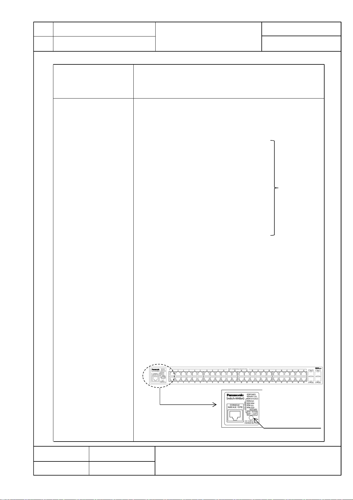
You can display the following items using the LED display change button.
Display for the connection with a connected terminal (Status mode), Display for
the 1000 Mbps transmission rate (GIGA mode), Display for the 100Mbps or 10 Mbps
transmission rate (Speed mode), Display for the full-duplex or half-duplex
transmission system (DUPLEX mode), Display for ports with a loop history (Loop
history mode), All port LED lamps can be turned OFF (ECO mode).
The mode at the start is called “Base mode”.
There are two types of Base modes : Status mode (factory default setting) and
ECO mode . You can change the Base mode by holding down the LED display change
button (for at least 3 sec).
When the Base mode is changed normally, all STATUS/ECO , GIGA , 100M , and
FULL LED lamps light up at the same time. When you release the button, the Base
mode is changed to the selected mode.
If the mode is changed to the GIGA mode, Speed mode, DUPLEX mode, or
Loop History mode and the LED display switch button is not used for one minute or
longer, the mode automatically returns to a Base mode (Status mode or ECO mode).
The Base mode is maintained even after the power is turned OFF.
Date issued
Date revised
LED display change button
May 26, 2015
Panasonic Life Solutions Networks Co., Ltd.
Oct 1, 2020
Page 4

Model
Name
Switch-M48eG
Model
No.
PN28480K-MY
5. Hardware Specifications
5-4. LED display Switch two types of Base mode s and their LEDs in the following way:
Product Specification
When Base mode is Status mode (factory default setting)
Press “LED DISPLAY CHANGE BUTTON” manually.
Automatic
Boot
Automatically returns to Base mode after 1 minute.
401-28480K-MY-SP02
Page 4 of 10
Status mode
(Base mode)
When Base mode is ECO mode
Boot
ECO mode
(Base mode)
LED lamps for each mode and LED lamps for ports 1 to 48 correspond as the following.
(Table 1)
Port
LED
Left
Right
Display mode Behavior Description
STATUS/ECO
GIGA
100M
Full
LOOP
HISTORY
-
GIGA mode Speed mode
Status
mode
Port LED(Left)
GIGA
mode
Table 1
Green Light
Green Blink
Off
Green Light
Off
Green Light
Off
Green Light
Off
Green Light
Off
Orange Light
Off
Switch Base mode(keep pressing “LED DISPLAY
Press “LED DISPLAY CHANGE BUTTON” manually.
Automatic
Automatically returns to Base mode after 1 minute.
Speed
mode
Link is established
Transmitting and receiving data.
No device connected.
Link is established at 1000Mbps.
Link is established at 100Mbps or
10Mbps , or no device is connected.
Link is established at 100Mbps.
Link is established at 1000Mbps or
10Mbps , or no device is connected.
Link is established at full-duplex.
Link is established at half-duplex or
or no device is connected.
Loop has been detected within the
last 3 days.
No loop detection history.
Shutting down by loop detection.
Not shutting down by loop detection.
DUPLEX
mode
CHANGE BUTTON” over 3 seconds)
DUPLEX
mode
Loop History
mode
Loop History
mode
Date issued
Date revised
Port LED(Right)
May 26, 2015
Panasonic Life Solutions Networks Co., Ltd.
Oct 1, 2020
Page 5

Model
Name
Model
No.
Switch-M48eG
PN28480K-MY
6. Software Specifications
401-28480K-MY-SP02
Product Specification
Page 5 of 10
6-1. Configuration
6-2. Switching Hub Control
6-3. Rebooting
6-4. Supported Agent
6-5. Supported MIB
Control parameters can be set by the following procedures:
(1) Configuration from an asynchronous terminal connected to the console port.
(2) Configuration from a remote terminal connected via TELNET and SSH.
Switching Hub can be controlled by the following procedures:
(1) Control from an asynchronous terminal connected to the console port.
(2) Control from a remote terminal using SSH/TELNET and TCP/IP network
connection
(3) Control using SNMP Manager
The switching Hub operation status can be checked using the following functions.
(1) Function to display the CPU usage and memory usage
(2) SFP module status checking function (DDM: Digital Diagnostic Monitoring)
The system can be reset from the software in the following three modes:
(1) Warm start
(2) Reset to factory default
(3) Reset items other than the IP address to factory default
The reboot timer function can also be used in each mode.
Management protocol :SNMP v1/v2c/v3 (RFC1157,RFC1901,
RFC1908)
TELNET (RFC854)
SSH v2 (RFC4251,RFC4252,
RFC4253,RFC4254)
SNTP v3 (RFC1769)
Data transfer protocol :TFTP (RFC783,RFC1350)
RFC1213-MIB(MIBⅡ) (RFC 1213) (*1)
BRIDGE-MIB (RFC 4188) (*2)
SNMPv2-MIB (RFC 1907)
RMON-MIB (RFC 2819) Only etherStatsTable
SNMP-FRAMEWORK-MIB (RFC 2571)
SNMP-MPD-MIB (RFC 2572)
SNMP-NOTIFICATION-MIB (RFC 2573N)
SNMP-TARGET-MIB (RFC 2573T)
SNMP-USER-BASED-SM-MIB (RFC 2574)
SNMP-VIEW-BASED-ACM-MIB (RFC 2575)
SNMP-COMMUNITY-MIB (RFC 2576)
IP-MIB (RFC 4293) (*3)
IF-MIB (RFC 2233) Excluding IfMIB
IEEE8021-PAE-MIB Excluding dot1xPaeSupplicant
*1 Excluding following item
At, ipRouteTable, icmp, egp
*2 Excluding following item
dot1dStp, dot1dSr, dot1dStatic
*3 Excluding following item
ipDefaultRouterTable, ipv6RouterAdvertTable
6-6. System log Maximum number to be kept: 256
System log transfer (IPv4/IPv6)
Date issued
Date revised
May 26, 2015
Oct 1, 2020
Panasonic Life Solutions Networks Co., Ltd.
Page 6

Model
Name
Model
No.
Switch-M48eG
PN28480K-MY
6. Software Specifications
401-28480K-MY-SP02
Product Specification
Page 6 of 10
6-7. Loop detection
6-8. Others
Turns on the port LED with a orange light when a loop occurs in the corresponding port.
At this time, the relevant port automatically shuts down to prevent loop from occurring.
SNMP trap can be sent to notify the incident to the administrator.
During loop is occurring, or if loop has occurred within the latest 3 days,
LOOP HISTORY LED blinks to notify this.
• Loop detection setting
Enabled (factory default setting)
Enabled/disabled can be switched by configuring a setting using
the console, or by pressing "LED DISPLAY CHANGE BUTTON"
for 10 seconds or more.
The setting is kept even when the power is turned OFF.
• Loop detection port
Enabled: Ports 1 to 44 (factory default setting)
Disabled: Ports 45 and 48 (factory default setting)
• Loop shutoff time
60 to 86400 sec. (Factory default setting: 60 sec.)
The set time Port LED lights up orange and the port shuts off.
• Loop history retention time
3 days
The LOOP HISTORY LED lamp flashes for three days.
The Port LED lamp also remains lit for three days after
the loop is eliminated.
ZEQUO assist
Syslog Client (Transfers system logs to the Syslog server.)
TFTP Client (Upgrades the software and saves/loads configuration information.)
Login RADIUS (login authentication function by the RADIUS server)
7. Layer 2 Switching Functions
7-1. Port grouping Members of the port group can communicate only among member ports in
the same group.
(Number of group registrations: 256)
7-2. VLAN
7-3. Trunking IEEE802.ad Link Aggregation function (STATIC)
7-4. Port Monitoring Traffic of the target port can be copied to the specified port and transmitted.
7-5. QoS
7-6. Authentication Function IEEE802.1X Port-based authentication
7-7. Access control Access control can be controlled by the following parameters:
IEEE802.1Q Tag VLAN Protocol
Port Base VLAN
Number of VLAN registrations: 256 (including default)
Internet Mansion function
Up to 8 groups can be created (up to 8 ports per group).
(Two or more target ports can be specified.)
IEEE802.1p 4 levels of Priority Queue supported
(Strict priority queuing )
(EAP-MD5/TLS/PEAP Authentication method)
(1) IP address (Source or Destination)
(2) IPv6 address (Source or Destination)
(3) MAC address (Source or Destination)
(4) TCP/UDP port number (Source or Destination)
(5) VLAN ID
(6) IEEE 802.1p Priority
(7) DSCP
(8) Protocol
(9) ICMP type
(10)TCP SYN Flag
Date issued
Date revised
May 26, 2015
Panasonic Life Solutions Networks Co., Ltd.
Oct 1, 2020
Page 7

Model
Name
Model
No.
Switch-M48eG
PN28480K-MY
7. Layer 2 Switching functions
401-28480K-MY-SP02
Product Specification
Page 7 of 10
7-8. Fan control
7-9. Time configuration
8. Connector Pin Arrangement
8-1. Port 1 - 48
Status
MDI-X
8-2. Console port
MDI
Pin No.
Signal
Signal
Pin No.
1
2
3
4
12364 587
BI_DB+
BI_DA+
BI_DB-
BI_DA-
Signal
NC
NC
TXD
GND
Set the number of revolutions of the fan according to the operating environment
temperature.
Fan control
High speed
Low speed
SNTP-based time synchronization function
Manual mode setting
BI_DA+
BI_DB+
Pin No.
5
6
7
8
Operating environment
temperature
0-50℃
0-40℃
BI_DA- BI_DD+
BI_DB- BI_DC+
Signal
GND
RXD
NC
NC
BI_DD-
BI_DC-
Remarks
Factory default
Set the fan to high speed when using this
Switching Hub where the operating environment
temperature is between 0 and 50℃
BI_DC+
BI_DD+
BI_DC-
BI_DD-
Pin No.
Pin No.
1 2 3 4 5 6 7 8
1 2 3 4 5 6 7 8
9. Installation Procedures and Accessories
9-1.Installation Procedures Mounting to rack
9-2.Accessories
(1) Installation Guide :1
(2) CD-ROM(*1) :1
(3) Rubber foot :4
(4) Mounting bracket (for 19-inch rack) :2
(5) Screw(for 19-inch rack) :4
(6) Screw (for fixing the main unit and the 19 inch rack mount bracket) :8
(7) Power cord (CEE7/7)(*2) :1
*1 We discontinued the CD-ROM from October 2020's production lots.
*2 The attached power cord is dedicated for AC 100 - 240 V use.
Date issued
Date revised
May 26, 2015
Panasonic Life Solutions Networks Co., Ltd.
Oct 1, 2020
Page 8

Model
Name
Model
No.
Switch-M48eG
PN28480K-MY
10. Optional Accessories
401-28480K-MY-SP02
Product Specification
Page 8 of 10
10-1. 1000BASE-SX
SFP Module
(Model No. :PN54021K-ID)
10-2. 1000BASE-LX
SFP Module
(Model No.:PN54023K-ID)
Fiber optic port connector type :LC connector (Duplex)
Standards : IEEE802.3z 1000BASE-SX
Transmission speed : 1000Mbps, full duplex
Compatible cable : Fiber cable
50/125μm Multi Mode Fiber
62.5/125μm Multi Mode Fiber
Maximum transmission distance : 550 m at 50/125 μm
220 m at 62.5/125 μm
Fiber optic port connector type :LC connector (Duplex)
Standards : IEEE802.3z 1000BASE-LX
Transmission speed : 1000Mbps, full duplex
Compatible cable : Fiber cable
10/125μm Single Mode Fiber
50/125μm Multi Mode Fiber
62.5/125μm Multi Mode Fiber
Maximum transmission distance : 10 km when Single Mode Fiber is used
550 m when Multi Mode Fiber is used
Date issued
Date revised
May 26, 2015
Panasonic Life Solutions Networks Co., Ltd.
Oct 1, 2020
Page 9

Model
Name
Model
No.
Switch-M48eG
Product Specification
PN28480K-MY
11. Prohibitions when Using the Product to Guarantee Safety
The manufacturer assumes no responsibility for any problems occurring when the following conditions are not satisfied.
Observe the following items when using the product.
(1) Do not use power supply other than AC 100 - 240 V.
Deviation could lead to fire, electric shock, and/or equipment failure.
(2) Do not disassemble and/or modify this Switching Hub.
Deviation could lead to fire, electric shock, and/or equipment failure.
(3) Do not put foreign objects (such as metal and combustible) into the opening (such as twisted pair port, console port),
and/or do not drop them into the inside of the Switching Hub.
Deviation could lead to fire, electric shock, and/or equipment failure.
(4) Do not connect equipments other than 10BASE-T/100BASE-TX/1000BASE-T to twisted pair port.
Deviation could lead to fire, electric shock, and/or equipment failure.
(5) Do not place this Switching Hub in harsh environment (such as near water, high humid, and/or high dust).
Deviation could lead to fire, electric shock, and/or equipment failure.
(6) Do not place this Switching Hub under direct sunlight and/or high temperature.
Deviation could lead to high internal temperature and fire.
401-28480K-MY-SP02
Page 9 of 10
(7) Do not handle the power cord with wet hand.
Deviation could lead to electric shock, and/or equipment failure.
(8) Do not handle this Switching Hub and connection cables during a thunderstorm.
Deviation could lead to electric shock.
(9) Do not damage the power cord. Do not bend too tightly, stretch, twist, bundle with other cord, pinch, put under a heavy
object and/or heat it.
Damaged power cord could lead to fire, short, and/or electric shock.
(10) Do not install this Switching Hub at the location with continuous vibration or strong shock, or at the unstable location.
Deviation could lead to injury and/or equipment failure.
(11) Do not insert any modules other than the optional SFP modules (PN54021K-MY/PN54023K-MY) into the SFP extension
slot.
Deviation could lead to fire, electric shock, and/or equipment failure.
For the latest information about compatible SFP extension modules, check our website.
(12) Do not put this Switching Hub into fire.
Deviation could lead to explosion and/or fire.
(13) Do not use the supplied power cord for anything other than this product.
Deviation could lead to fire, electric shock, and/or equipment failure.
(14) Unplug the power cord in case of equipment failure.
Deviation, such as keeping connected for a long time, could lead to fire.
(15) Connect this Switching Hub to ground.
Deviation could lead to electric shock, malfunction, and/or equipment failure.
(16) Connect the power cord firmly to the power port.
Deviation could lead to electric fire, shock, and/or malfunction.
(17) Unplug the power cord if the STATUS/ECO LED (Status/ECO mode) blinks in orange (system fault).
Deviation, such as keeping connected for a long time, could lead to fire.
Date issued
May 26, 2015
Panasonic Life Solutions Networks Co., Ltd.
Date revised
Oct 1, 2020
Page 10

Model
Name
Model
No.
Switch-M48eG
Product Specification
PN28480K-MY
11. Prohibitions when Using the Product to Guarantee Safety
(18) Handle the Switching Hub carefully so that fingers or hands may not be damaged by twisted pair port, console port,
or power cord hook block.
12. Basic Instructions for the Use of This Product
(1) For inspection and/or repair, consult the retailer.
(2) Use commercial power supply from a wall socket, which is close and easily accessible to this Switching Hub.
(3) Unplug the power cord when installing or moving this Switching Hub.
(4) Unplug the power cord when cleaning this Switching Hub.
(5) Use this Switching Hub within the specifications. Deviation could lead to malfunction.
(6) Do not touch the metal terminal of the RJ45 connector, the modular plug of connected twisted pair cable.
Do not place charged objects in the proximity of them. Static electricity could lead to equipment failure.
(7) Do not put the modular plug of the connected twisted pair cable on objects that can carry static charge, such as carpet.
Do not place it in the proximity. Static electricity could lead to equipment failure.
(8) Do not put a strong shock, including dropping, to this Switching Hub.
Deviation could lead to equipment failure.
401-28480K-MY-SP02
Page 10 of 10
(9) Before connecting a console cable to the console port, discharge static electricity, for example by touching metal appliance
(do not discharge by touching this Switching Hub).
(10) Do not store and/or use this Switching Hub in the environment with the characteristics listed below.
(Store and/or use this Switching Hub in the environment in accordance with the specification.)
- High humidity. Possible spilled liquid (water).
- Dusty. Possible static charge (such as carpet).
- Under direct sunlight.
- Possible condensation. High/low temperature exceeding the specifications environment.
- Strong vibration and/or strong shock.
(11) Please use this Switching Hub in place where ambient temperature is from 0 to 50℃.
Failure to satisfy the conditions above may result in a fire, electric shock, equipment failure, and/or malfunction.
Such events are not covered by the warranty. Do not block the ventilator of the Switching Hub.
Blocked ventilator induces the heat accumulation inside, causing equipment failure and/or malfunction.
(12) When using two Switching Hubs, do not stack them. When you place them side by side, allow for a space of 20 mm or
more between them. This space is not necessary if you use supplied connection brackets.
(13) Operation is not guaranteed if a module other than the optional SFP extension modules (PN54021K-MY/PN54023K-MY) is
inserted into the SFP extension slot.
For the latest information about compatible SFP extension modules, check our website.
Date issued
Date revised
May 26, 2015
Panasonic Life Solutions Networks Co., Ltd.
Oct 1, 2020
 Loading...