

Panasonic SU-HTB880EB, SB-HWA880GN, SU-HTB880PP, SB-HWA880EG, SB-HWA880PP Service Manual
...
© Panasonic Corporation 2014. All rights reserved.
Unauthorized copying and distribution is a violation of
law.
PSG1405017CE
A6
Home Theater Audio System
Model No. SU-HTB880EB
SU-HTB880EG
SU-HTB880GN
SU-HTB880PP
SB-HWA880EB
SB-HWA880EG
SB-HWA880GN
SB-HWA880PP
SC-HTB880EB
SC-HTB880EG
SC-HTB880GN
SC-HTB880PP
Product Color: (K)...Black Type
TABLE OF CONTENTS
PAG E PAG E
1 Safety Precautions----------------------------------------------- 3
1.1. General Guidelines---------------------------------------- 3
1.2. Caution for AC Cord (For EB only)-------------------- 4
1.3. Before Repair and Adjustment ------------------------- 5
1.4. Protection Circuitry ----------------------------------------5
1.5. Caution For Fuse Replacement ------------------------5
1.6. Safety Part Information ----------------------------------- 6
2Warning--------------------------------------------------------------8

2
2.1. Prevention of Electrostatic Discharge (ESD)
to Electrostatically Sensitive (ES) Devices ----------8
2.2. Service caution based on Legal restrictions
(Lead Free Solder, (PbF))--------------------------------9
3 Service Navigation---------------------------------------------- 10
3.1. Service Information -------------------------------------- 10
4 Specifications---------------------------------------------------- 11
5 Location of Controls and Components------------------ 12
5.1. Main Unit & Active Subwoofer Key Button
Operations ------------------------------------------------- 12
5.2. Remote Control Key Button Operations ------------ 13
6 Service Mode----------------------------------------------------- 14
6.1. Service Mode Table 1----------------------------------- 14
6.2. Service Mode Table 2----------------------------------- 15
6.3. Service Mode Software Version Check Table----- 16
6.4. HDMI Version Display Table--------------------------- 17
6.5. Bluetooth Version Display Table---------------------- 17
6.6. Service Mode Model Name Display Table--------- 17
6.7. Service Mode Region Display Table ---------------- 17
6.8. Service Function Error Code -------------------------- 18
7 Troubleshooting Guide---------------------------------------- 19
8 Disassembly and Assembly Instructions--------------- 20
8.1. Service Fixture & Tools --------------------------------- 20
8.2. Disassembly flow chart ---------------------------------21
8.3. Type of Screws -------------------------------------------22
8.4. Main Parts Location Diagram ------------------------- 23
8.5. Disassembly of Main Unit (SU-HTB880) ---------- 24
8.6. Disassembly of Active Subwoofer (SBHWA880)--------------------------------------------------- 37
9 Service Position------------------------------------------------- 41
9.1. Main Unit (SU-HTB880) -------------------------------- 41
9.2. Active Subwoofer (SB-HWA880)--------------------- 45
10 Block Diagram --------------------------------------------------- 47
10.1. Main Unit (SU-HTB880) -------------------------------- 47
10.2. Active Subwoofer (SB-HWA880)--------------------- 52
11 Wiring Connection Diagram--------------------------------- 54
11.1. Main Unit (SU-HTB880) -------------------------------- 54
11.2. Active Subwoofer (SB-HWA880)--------------------- 55
12 Schematic Diagram--------------------------------------------- 57
12.1. Schematic Diagram Notes ----------------------------- 57
12.2. Main Unit (SU-HTB880) -------------------------------- 59
12.3. Active Subwoofer (SB-HWA880)--------------------- 76
13 Printed Circuit Board ------------------------------------------ 81
13.1. Main Unit (SU-HTB880) ------------------------------- 81
13.2. Active Subwoofer (SB-HWA880) -------------------- 87
14 Voltage and Waveform Measurement -------------------- 89
14.1. Voltage Measurement----------------------------------- 89
15 Exploded View and Replacement Parts List----------- 99
15.1. Cabinet Parts Location-1 (SU-HTB880) ------------ 99
15.2. Cabinet Parts Location-2 (SU-HTB880) ---------- 100
15.3. Cabinet Parts Location-3 (SU-HTB880) ---------- 101
15.4. Cabinet Parts Location (SB-HWA880)------------ 102
15.5. Packaging (SC-HTB880) ----------------------------- 103
15.6. Mechanical Replacement Parts List --------------- 105
15.7. Electrical Replacement Parts List ------------------ 107
3
1 Safety Precautions
1.1. General Guidelines
1. IMPORTANT SAFETY NOTICE
There are special components used in this equipment which are important for safety. These parts are marked by in the
Schematic Diagrams, Circuit Board Layout, Exploded Views and Replacement Parts List. It is essential that these critical parts
should be replaced with manufacturer’s specified parts to prevent X-RADIATION, shock, fire, or other hazards. Do not modify
the original design without permission of manufacturer.
2. An Isolation Transformer should always be used during the servicing of AC Adaptor whose chassis is not isolated from the AC
power line. Use a transformer of adequate power rating as this protects the technician from accidents resulting in personal
injury from electrical shocks. It will also protect AC Adaptor from being damaged by accidental shorting that may occur during
servicing.
3. When servicing, observe the original lead dress. If a short circuit is found, replace all parts which have been overheated or
damaged by the short circuit.
4. After servicing, see to it that all the protective devices such as insulation barriers, insulation papers shields are properly
installed.
5. After servicing, make the following leakage current checks to prevent the customer from being exposed to shock hazards.
1.1.1. Leakage Current Cold Check
1. Unplug the AC cord and connect a jumper between the two prongs on the plug.
2. Using an ohmmeter measure the resistance value, between the jumpered AC plug and each exposed metallic cabinet part on
the equipment such as screwheads, connectors, control shafts, etc. When the exposed metallic part has a return path to the
chassis, the reading should be between 1MΩ and 5.2Ω. When the exposed metal does not have a return path to the chassis,
the reading must be
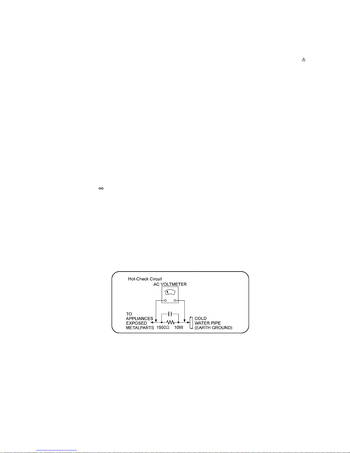
1.1.2. Leakage Current Hot Check
1. Plug the AC cord directly into the AC outlet. Do not use an isolation transformer for this check.
2. Connect a 1.5kΩ, 10 watts resistor, in parallel with a 0.15μF capacitors, between each exposed metallic part on the set and a
good earth ground such as a water pipe, as shown in Figure 1-1.
3. Use an AC voltmeter, with 1000 ohms/volt or more sensitivity, to measure the potential across the resistor.
4. Check each exposed metallic part, and measure the voltage at each point.
5. Reverse the AC plug in the AC outlet and repeat each of the above measurements.
6. The potential at any point should not exceed 0.75 volts RMS. A leakage current tester (Simpson Model 229 or equivalent)
may be used to make the hot checks, leakage current must not exceed 1/2 milliamp. should the measurement is outside of
the limits specified, there is a possibility of a shock hazard, and the equipment should be repaired and re-checked before it is
returned to the customer.
Figure 1-1
4
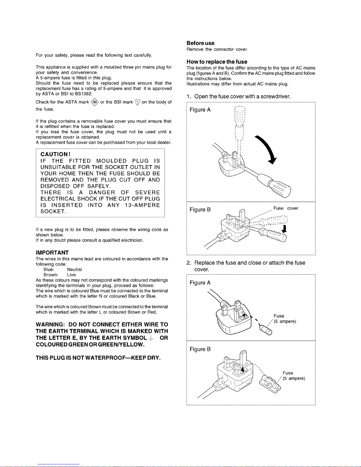
1.2. Caution for AC Cord (For EB only)
5
1.3. Before Repair and Adjustment
1.3.1. Main Unit (SU-HTB880)
Disconnect AC power, discharge unit AC Capacitors (C5700, C5701, C5702, C5703, C5704 and C5705) through a 10W, 1W resistor to ground.
Caution : DO NOT SHORT-CIRCUIT DIRECTLY (with a screwdriver blade, for instance), as this may destroy solid state devices.
After repairs are completed, restore power gradually using a variac, to avoid overcurrent.
• Current consumption at AC 120 V, 60 Hz during power on at no signal with volume minimum, should be ~150 mA (For PP only).
• Current consumption at AC 220 V ~ 240 V, 50 Hz during power on at no signal with volume minimum, should be ~200 mA (For
EB/EG/GN only).
1.3.2. Active Subwoofer (SB-HWA880)
Disconnect AC power, discharge unit AC Capacitors (C5700, C5701, C5702, C5703, C5704 and C5705) through a 10W, 1W resistor to ground.
Caution : DO NOT SHORT-CIRCUIT DIRECTLY (with a screwdriver blade, for instance), as this may destroy solid state devices.
After repairs are completed, restore power gradually using a variac, to avoid overcurrent.
• Current consumption at AC 120 V, 60 Hz during power on at link with volume minimum, (Selector : BD/DVD mode) should be
~200 mA (For PP only).
• Current consumption at AC 220 V ~ 240 V, 50 Hz during power on at link with volume minimum, (Selector : BD/DVD mode)
should be ~200 mA (For EB/EG/GN only).
1.4. Protection Circuitry
The protection circuitry may have operated if either of the following conditions are noticed:
• No sound is heard when the power is turned on.
• Sound stops during a performance.
The function of this circuitry is to prevent circuitry damage if, for example, the positive and negative speaker connection wires are
"shorted", or if speaker systems with an impedance less than the indicated rated impedance of the amplifier are used.
If this occurs, follow the procedure outlines below:
1. Turn off the power.
2. Determine the cause of the problem and correct it.
3. Turn on the power once again after one minute.
Note:
When the protection circuitry functions, the unit will not operate unless the power is first turned off and then on again.
1.5. Caution For Fuse Replacement

6
1.6. Safety Part Information
Safety Parts List:
There are special components used in this equipment which are important for safety.
These parts are marked by in the Schematic Diagrams & Replacement Parts List. It is essential that these critical parts should
be replaced with manufacturer’s specified parts to prevent shock, fire or other hazards. Do not modify the original design without
permission of manufacturer.
1.6.1. Main Unit (SU-HTB880)
Safety Ref. No. Part No. Part Name & Description Remarks
14 RGN3455-K1 NAME PLATE EB,EG
14 RGN3456-K NAME PLATE PP
14 RGN3458-K1 NAME PLATE GN
39 RMZ1443A SMPS PC SHEET
40 RMZ1455 MAIN PC SHEET
PCB2 REP5073B SMPS P.C.B. (RTL)PP
PCB2 REP5073C SMPS P.C.B. (RTL)EB, EG, GN
DZ5701 ERZV10V511CS ZNR (E.S.D)
L5702 G0B922G00004 LINE FILTER
L5703 G0B203G00005 LINE FILTER
T5701 G4DYA0000573 TRANSFORMER
PC5720 B3PBA0000579 PHOTO COUPLER
PC5760 B3PBA0000579 PHOTO COUPLER
F1 K5G312Y00007 FUSE
P5701 K2AA2B000011 AC INLET EB,EG,GN
P5701 K2AB2B000007 AC INLET PP
R5700 ERJ8GEYJ105V 1M 1/4W
R5701 ERJ8GEYJ105V 1M 1/4W
R5710 ERJ8GEYJ105V 1M 1/4W
C5700 F1BAF1020020 1000pF
C5701 F0CAF104A105 0.1uF
C5702 F0CAF104A105 0.1uF
C5703 F0CAF104A105 0.1uF
C5704 F1BAF471A013 470pF
C5705 F1BAF471A013 470pF
7
1.6.2. Active Subwoofer (SB-HWA880)
1.6.3. System (SC-HTB880)
Safety Ref. No. Part No. Part Name & Description Remarks
65 RGN3442-K SPEC LABEL EB, EG
65 RGN3444-K SPEC LABEL GN
65 RGN3446-K SPEC LABEL PP
75 REX1703 1P RED WIRE (SMPS - SW AC INLET)
77 REX1704 1P BLACK WIRE (SMPS - SW AC INLET)
PCB2 REP5036BB SW AC INLET P.C.B. (RTL) PP
PCB2 REP5036CB SW AC INLET P.C.B. (RTL) EB, EG, GN
DZ5701 ERZV10V511CS ZNR
L5702 G0B203G00005 LINE FILTER
L5703 G0B612H00005 INDUCTOR PP
L5703 G0B203G00005 INDUCTOR EB, EG, GN
T5701 G4DYA0000441 TRANSFORMER PP
T5701 G4DYA0000485 TRANSFORMER EB, EG, GN
T5751 G4DYA0000592 TRANSFORMER
PC5701 B3PBA0000579 PHOTO COUPLER
PC5720 B3PBA0000579 PHOTO COUPLER
PC5799 B3PBA0000579 PHOTO COUPLER
F1 K5G312Y00007 FUSE
P5701 K2AA2B000011 AC INLET EB, EG, GN
P5701 K2AB2B000007 AC INLET PP
R5700 ERJ8GEYJ105V 1M 1/4W EB, EG, GN
R5700 ERJ8GEYJ155V 1.5M 1/4W PP
R5701 ERJ8GEYJ105V 1M 1/4W EB, EG, GN
R5701 ERJ8GEYJ155V 1.5M 1/4W PP
R5710 ERJ8GEYJ105V 1M 1/4W EB, EG, GN
R5710 ERJ8GEYJ155V 1.5M 1/4W PP
C5700 F1BAF1020020 1000pF
C5701 F0CAF104A105 0.1uF
C5702 F0CAF104A105 0.1uF
C5703 F0CAF104A105 0.1uF
C5704 F1BAF1020020 1000pF PP
C5704 F1BAF471A013 470pF EB, EG, GN
C5705 F1BAF1020020 1000pF PP
C5705 F1BAF471A013 470pF EB, EG, GN
C5706 F1BAF1020020 1000pF
Safety Ref. No. Part No. Part Name & Description Remarks
A2 K2CB2CB00022 AC CORD PP
A2 K2CJ2YY00093 AC CORD GN
A2 K2CQ2YY00119 AC CORD EG
A2 K2CT2YY00097 AC CORD EB
A3 RQT9903-Y O/I BOOK (En/Cf) PP
A3 RQT9904-1B O/I BOOK (En) EB,GN
A3 RQT9905-1D O/I BOOK (Ge/Fr/It) EG
A3 RQT9906-1E O/I BOOK (Sw/Da/Du) EG
A3 RQT9907-1H O/I BOOK (Sp/Fi) EG
8
2Warning
2.1. Prevention of Electrostatic Discharge (ESD) to Electrostatically Sensitive (ES) Devices
Some semiconductor (solid state) devices can be damaged easily by static electricity. Such components commonly are called Electrostatically Sensitive (ES) Devices.
The following techniques should be used to help reduce the incidence of component damage caused by electrostatic discharge
(ESD).
1. Immediately before handling any semiconductor component or semiconductor-equipped assembly, drain off any ESD on your
body by touching a known earth ground. Alternatively, obtain and wear a commercially available discharging ESD wrist strap,
which should be removed for potential shock reasons prior to applying power to the unit under test.
2. After removing an electrical assembly equipped with ES devices, place the assembly on a conductive surface such as aluminum foil, to prevent electrostatic charge buildup or exposure of the assembly.
3. Use only a grounded-tip soldering iron to solder or unsolder ES devices.
4. Use only an anti-static solder removal device. Some solder removal devices not classified as “anti-static (ESD protected)” can
generate electrical charge sufficient to damage ES devices.
5. Do not use freon-propelled chemicals. These can generate electrical charges sufficient to damage ES devices.
6. Do not remove a replacement ES device from its protective package until immediately before you are ready to install it. (Most
replacement ES devices are packaged with leads electrically shorted together by conductive foam, aluminum foil or comparable conductive material).
7. Immediately before removing the protective material from the leads of a replacement ES device, touch the protective material
to the chassis or circuit assembly into which the device will be installed.
CAUTION:
Be sure no power is applied to the chassis or circuit, and observe all other safety precautions.
8. Minimize bodily motions when handling unpackaged replacement ES devices. (Otherwise harmless motion such as the
brushing together of your clothes fabric or the lifting of your foot from a carpeted floor can generate static electricity (ESD) sufficient to damage an ES device).
9
2.2. Service caution based on Legal restrictions (Lead Free Solder, (PbF))
The lead free solder has been used in the mounting process of all electrical components on the printed circuit boards used for this
equipment in considering the globally environmental conservation.
The normal solder is the alloy of tin (Sn) and lead (Pb). On the other hand, the lead free solder is the alloy mainly consists of tin
(Sn), silver (Ag) and Copper (Cu), and the melting point of the lead free solder is higher approx.30 degrees C (86°F) more than that
of the normal solder.
Definition of PCB Lead Free Solder being used
Service caution for repair work using Lead Free Solder (PbF)
• The lead free solder has to be used when repairing the equipment for which the lead free solder is used.
(Definition: The letter of “PbF” is printed on the PCB using the lead free solder.)
• To put lead free solder, it should be well molten and mixed with the original lead free solder.
• Remove the remaining lead free solder on the PCB cleanly for soldering of the new IC.
• Since the melting point of the lead free solder is higher than that of the normal lead solder, it takes the longer time to melt the
lead free solder.
• Use the soldering iron (more than 70W) equipped with the temperature control after setting the temperature at 350±30 degrees
C (662±86°F).
Recommended Lead Free Solder (Service Parts Route.)
• The following 3 types of lead free solder are available through the service parts route.
RFKZ03D01K-----------(0.3mm 100g Reel)
RFKZ06D01K-----------(0.6mm 100g Reel)
RFKZ10D01K-----------(1.0mm 100g Reel)
Note
* Ingredient: Tin (Sn), 96.5%, Silver (Ag) 3.0%, Copper (Cu) 0.5%, Cobalt (Co) / Germanium (Ge) 0.1 to 0.3%
The letter of “PbF” is printed either foil side or components side on the PCB using the lead free solder.
(See right figure)

10
3 Service Navigation
3.1. Service Information
This service manual contains technical information which will allow service personnel’s to understand and service this model.
Please place orders using the parts list and not the drawing reference numbers.
If the circuit is changed or modified, this information will be followed by supplement service manual to be filed with original service
manual.

11
4 Specifications
Q Amplifier Section
RMS output power: Dolby Digital Mode
Front ch (L, R ch) 50 W per channel (6 Ω), 1 kHz,
10% THD
Center ch (C ch) 50 W per channel (6 Ω), 1 kHz,
10% THD
Surround ch (L, R ch) 50 W per channel (6 Ω), 1 kHz,
10% THD
Subwoofer ch 250 W per channel (8 Ω), 100 Hz,
10% THD
Total RMS Dolby Digital mode
power
500 W
FTC output power: Dolby Digital Mode (For PP only)
Front ch (L, R ch) 30 W per channel (6 Ω), 120 Hz to
20 kHz, 1% THD
Center ch (C ch) 30 W per channel (6 Ω), 120 Hz to
20 kHz, 1% THD
Surround ch (L, R ch) 30 W per channel (6 Ω), 120 Hz to
20 kHz, 1% THD
Subwoofer ch 90 W per channel (8 Ω), 40 Hz to
200 Hz, 1% THD
Total FTC Dolby Digital mode
power
245 W
Q Terminal Section
HDAVI Control This unit supports “HDAVI Control
5” function.
HDMI AV input (BD/DVD, AUX) 2
Input connector Type A (19 pin)
HDMI AV output (TV (ARC)) 1
Output connector Type A (19 pin)
Digital audio input (TV)
Optical digital input Optical terminal
Sampling frequency 32 kHz, 44.1 kHz, 48 kHz
88.2 kHz, 96 kHz (only LPCM)
Audio format LPCM, Dolby Digital, DTS Sound
Surround
IR Blaster
Terminal Type 3.5 mm (1/8”) jack
USB Port For service use only.
Q General
Power consumption Main Unit: 33 W
Main Unit: 31 W (For PP)
Active subwoofer: 46 W
In standby condition
Main Unit
*1
(When “BLUETOOTH STANDBY” is “OFF”) : Approx. 0.49 W
(When “BLUETOOTH STANDBY” is “OFF”) : Approx. 0.4 W (For PP)
(When “BLUETOOTH STANDBY” is “ON”) : Approx. 3.0 W
Active subwoofer
Power switch off : Approx. 0.2 W
The wireless link is not activated : Approx. 0.4 W
Power supply AC 120 V, 60 Hz (For PP)
AC 220 V to 240 V, 50 Hz (For EB/EG/GN)
Dimensions (W x H x D)
Main Unit
For table top layout 1125 mm x 51 mm x 121 mm
(44 9/32" x 2" x 4 3/4")
For wall mounting layout 1125 mm x 122.5 mm x 56.5 mm
(44 9/32" x 4 13/16" x 2 7/32")
Active subwoofer 180 mm x 408 mm x 306 mm
(7 3/32" x 16 1/16" x 12 1/16")
Mass (Weight)
Main Unit
For table top layout Approx. 3.1 kg (6.8 lbs)
For wall mounting layout Approx. 3.2 kg (7.1 lbs)
Active subwoofer 5.4 kg (11.9 lbs)
Operating temperature range 0°C to +40°C
(+32°F to +104°F)
Operating humidity range 20% to 80 % RH
(no condensation)
Q Speaker Section
Front speakers (Build-in)
Woofer 6.5 cm (2 1/2”) cone type x 1/ch
Tweeter 2.5 cm (1”) Semi-Dome type x 1/
ch
Center speaker (Build-in)
Full range 6.5 cm (2 1/2”) cone type x 1
Surround speakers (Built-in)
Full range 6.5 cm (2 1/2”) cone type x 1/ch
Active subwoofer
Woofer 16 cm (6 1/2”) cone type x 1
Q Wireless section
Wireless module
Frequency Range 2.40335 GHz to 2.47735 GHz
Number of channels 38
Q Bluetooth
®
Section
Bluetooth
®
system specifica-
tion
Bluetooth® Ver.3. 0
Wireless equipment classification
Class 2
Supported profiles A2DP
Operating frequency 2.4 GHz band FH-SS
Operating distance 10 m (33 ft) Line of Sight
Supported codec
aptX
®
, AAC, SBC
• Specifications are subject to change without notice.
• Mass and dimensions are approximate.
• Total harmonic distortion is measured by the digital spectrum analyzer.
*1
: When the other connected devices are turned off
Q System: SC-HTB880EBK
MAIN SPEAKER UNIT : SU-HTB880EBK
ACTIVE SUBWOOFER : SB-HWA880EBK
Q System: SC-HTB880EGK
MAIN SPEAKER UNIT : SU-HTB880EGK
ACTIVE SUBWOOFER : SB-HWA880EGK
Q System: SC-HTB880GNK
MAIN SPEAKER UNIT : SU-HTB880GNK
ACTIVE SUBWOOFER : SB-HWA880GNK
Q System: SC-HTB880PPK
MAIN SPEAKER UNIT : SU-HTB880PPK
ACTIVE SUBWOOFER : SB-HWA880PPK
12
5 Location of Controls and Components
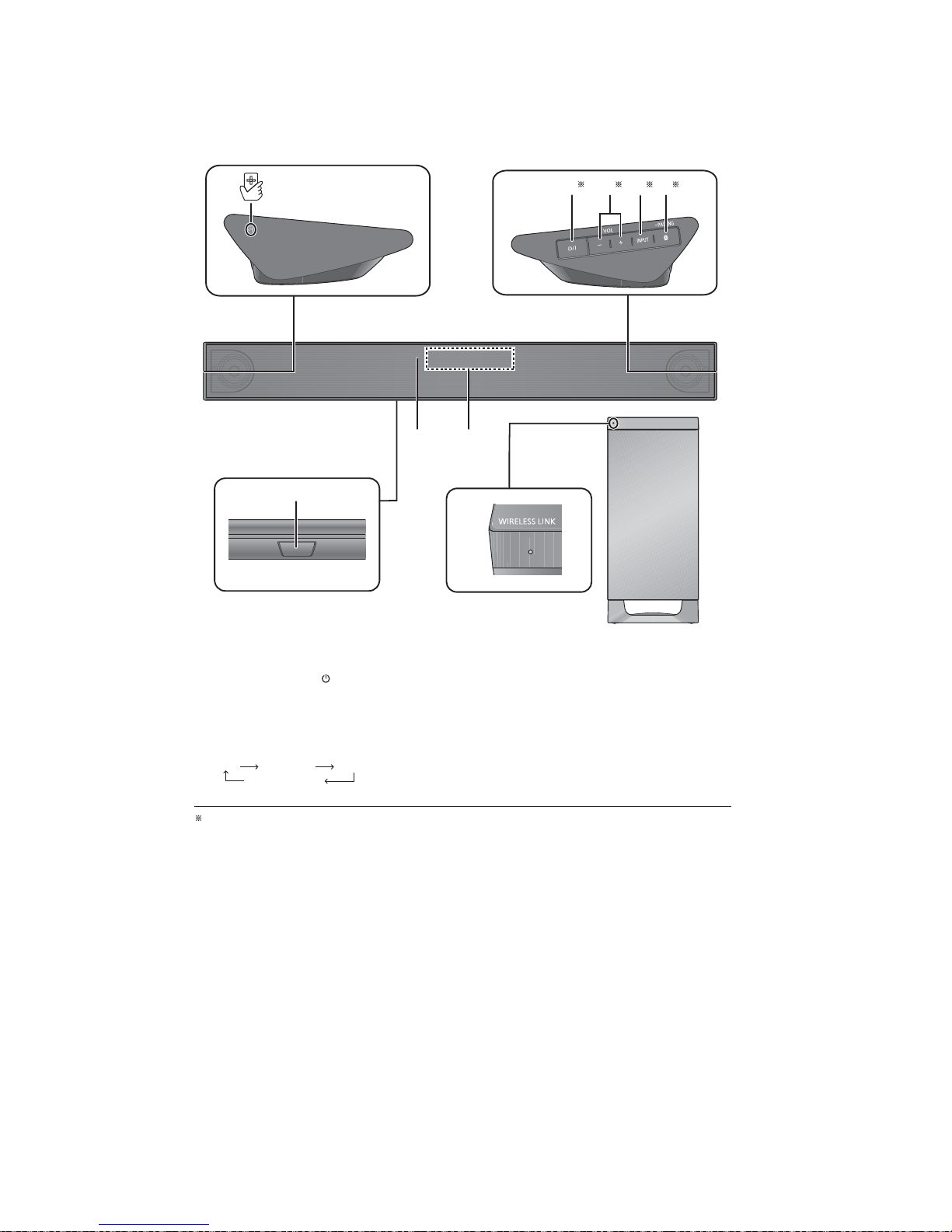
5.1. Main Unit & Active Subwoofer Key Button Operations
1 NFC touch area
2 Standby/on switch ( )
Touch to switch the unit from on to standby
mode or vice versa. In standby mode, the unit
is still consuming a small amount of power.
3 Adjust the volume on this system
4 Select the input source
“TV” “BD/DVD” “AUX”
“BLUETOOTH”
5 Select the Bluetooth device as the source
6 Remote control signal sensor for table top
layout
7 Remote control signal sensor for wall
mounting layout
8 Display
9 WIRELESS LINK indicator
These switches workjust by touching the marks. Each time you touch the switch, therewill be a beep sound.
8
9
7
1
3 4 52
6
Main unit
Active subwoofer
/I
®
13
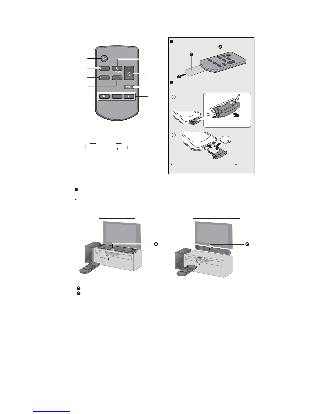
5.2. Remote Control Key Button Operations
1 Turn the main unit on or o
2 Select the input source
“TV” “BD/DVD” “AUX”
“BLUETOOTH”
3 Select the setup menu
4 Select the sound menu
5
Select the Bluetooth device as the source
6 Adjust the volume on this system
7Mute
8 Select and conrm the option
About remote control signal sensor
The remote control signal sensor is located on the main unit.
Use the remote control within the correct operation range.
Distance: Within approx. 7 m (23 ft) directly in front
Angle: Approx. 30
o
left and right
Remote control signal sensor for table top layout
Remote control signal sensor for wall mounting layout
SOUND
1
5
6
7
8
2
INPUT
SETUP
OK
3
4
Before using for the first time
Remove the insulation sheet .
To replace a button-type battery
Battery type: CR2025 3V (Lithium battery)
Set the button-type battery with its ( ) mark
facing upward.
For table top layout
For wall mounting layout
®
2
1
14
6 Service Mode
This unit is equipped with features of service mode mode setting for checking the functions & reliability.
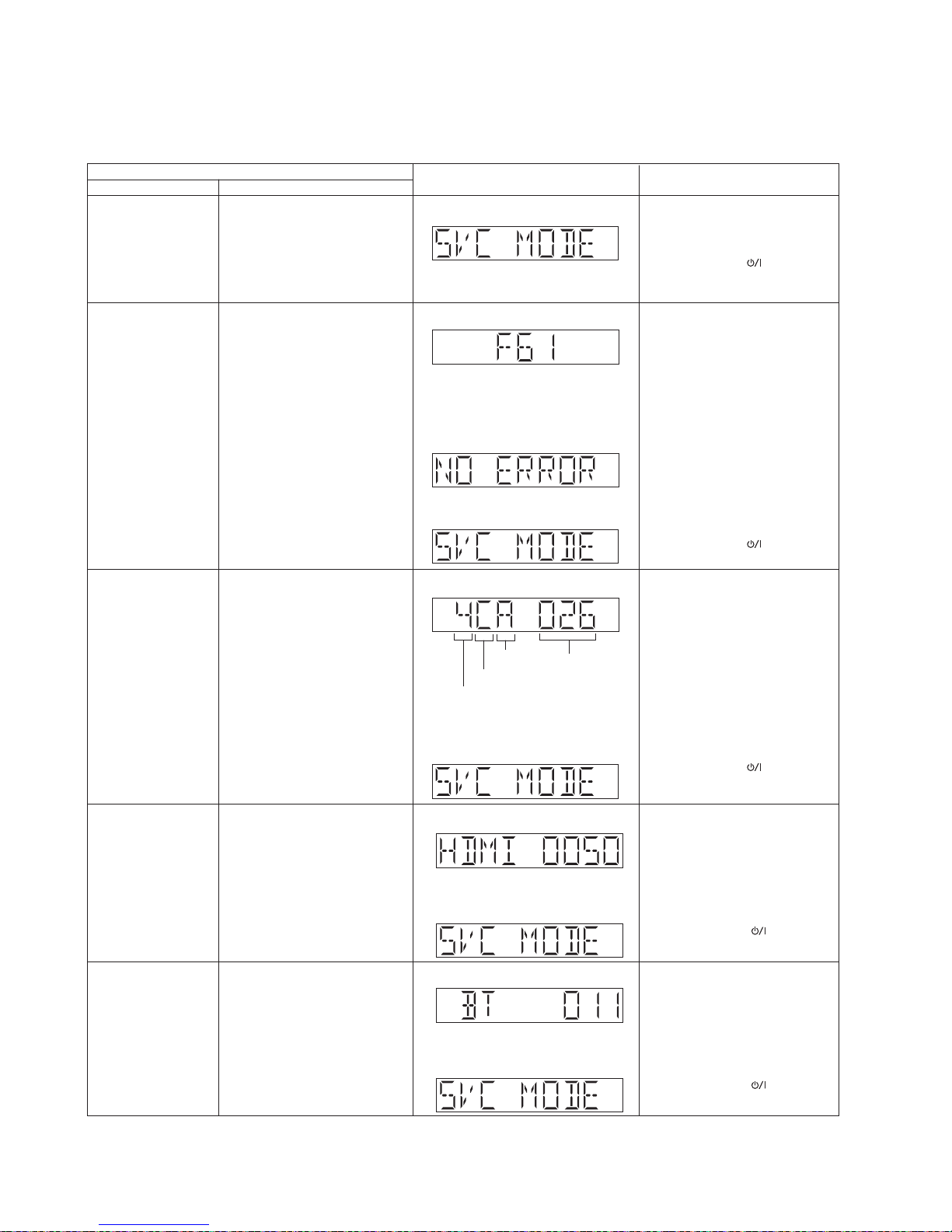
6.1. Service Mode Table 1
Press [VOL+] button 2 times on the
remote control.
Service Mode Upon entering into Service Mode
Item
FL display Key operation
Mode name Description
Error code information Example: F61, F76,F70HDMI
Example:
Example:
Error History Display by pressing
button, it goes back its history list.
Software Version
information
Display the current SW version
Software Version display is being
indicated in FL display in the
format of [4CB XXX].
1) 4 represent the Sales Year
2) C represent the Model Type
3) B represent the ROM Type
4) xxx represent the Version
number (Range from 000-999)
Refer to 6.3 for more information
HDMI Version display is being
indicated in FL display in the
format of [HDMI XXXX].
Refer to 6.4 for more information
HDMI Version
information
Display the HDMI Version number
The [SVC MODE] display will appear
after 3s,
The [SVC MODE] display will appear
after 3s,
Example:
Year of sales
ROM type
Model type
Running
version
number
In service mode:
Press [INPUT] button on the remote
control.
Error History Display by pressing
button, it goes back its history list.
After Pressing [INPUT] key, display
the last encounter Error display,
subsequent pressed will displayed
the second last Error and so on.
(Maximun of 10 display and if the
11th Error occurred, it will replace
the 1st error display, First IN First
OUT approach)
Refer to 6.6 for more information
In self diagnostic mode:
Press [VOL+] button 1 time on the
remote control.
Example: If already at the last error
display (earlier error) or No Error Log,
pressing [INPUT] key on the remote
control, [NO ERROR] will display
Pressing and hold [VOL-] on main
XQLWWKHQSUHVV>ź@IROORZE\>Ÿ@
using the remote control.
7RH[LWSUHVVWKH>TA] on the main
unit or using the remote control.
8QSOXJWKH$&FRUG
7RH[LWSUHVVWKH>TA] on the main
unit or using the remote control.
7RH[LWSUHVVWKH>TA] on the main
unit or using the remote control.
7RH[LWSUHVVWKH>TA] on the main
unit or using the remote control.
The [SVC MODE] display will appear
after 3s,
Press [VOL+] button 3 times on the
remote control.
Bluetooth Version display is being
indicated in FL display in the
format of [ BT XXX].
Refer to 6.5 for more information
Bluetooth Version
information
Display the Bluetooth Version
number
The [SVC MODE] display will appear
after 3s,
Example:
7RH[LWSUHVVWKH>TA] on the main
unit or using the remote control.
15
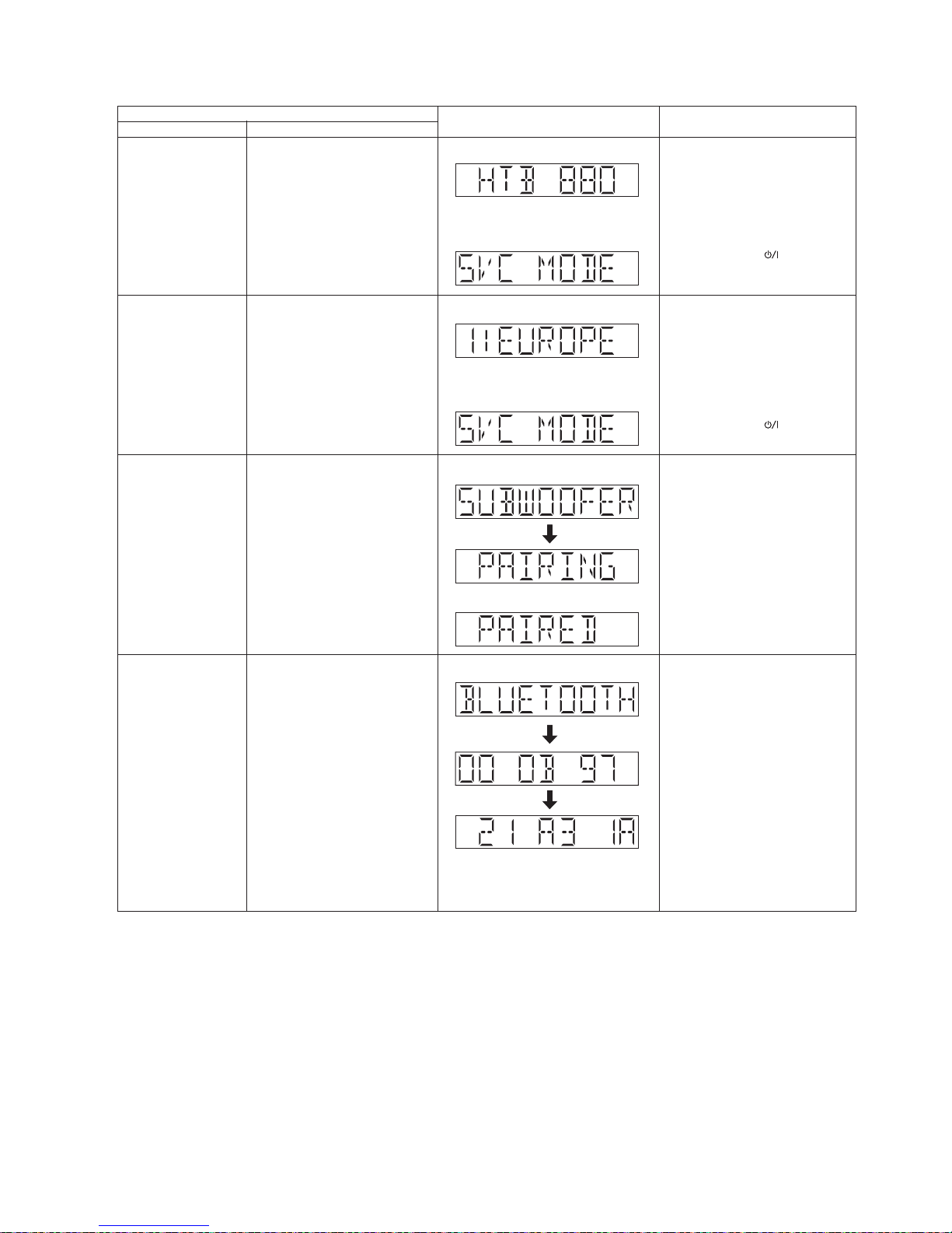
6.2. Service Mode Table 2
Item
FL display Key operation
Mode name Description
Press [VOL+] button 5 times on the
remote control.
Region information Region Setting
Example:
Refer to 6.7 for more information
7RH[LWSUHVVWKH>7$] on the main
unit or using the remote control.
7RH[LWSUHVVWKH>7$] on the main
unit or using the remote control.
Press [VOL+] button 4 times on the
remote control.
02'(/+7%;;;;;;VWDQG
IRUPRGHOQXPEHU(J
Refer to 6.6 for more information
0RGHO1DPH
information
'LVSOD\WKHPRGHOQDPH
The [SVC MODE] display will appear
after 3s,
Example:
The [SVC MODE] display will appear
after 3s,
3UHVV>%/8(7227+@EXWWRQRQWKH
remote control.
%OXHWRRWKinformation %OXHWRRWK6HWWLQJ
'LVSOD\VWE\WHRI%OXHWRRWK
0RGXOH0$&$''5(66IRU
VHFDQGIROORZHGE\ODVWWKE\WH
;;;;;; VWE\WHRIPDF,'
/()7DOLJQHG
Example:
3UHVV>6(783@EXWWRQRQWKHUHPRWH
control.
3UHVVDQGKROG>,1387@EXWWRQRQ
the remote control.
Press [VOL +] button on the main set
for 4sec.
or
+
:LUHOHVV6XEZRRIHU
Pairing
Pairing Setting
$FWXDO'LVSOD\GXULQJ
6XEZRRIHU3DLULQJ
>68%:22)(5@!>3$,5,1*@
7RJJOHGLVSOD\
$FWXDO'LVSOD\DIWHU6XEZRRIHU
KDGEHHQ3DLUHG
>3$,5('@
'LVSOD\/DVWE\WHRI%OXHWRRWK
0RGXOH0$&$''5(66IRU
VHFEHIRUHUHWXUQWRGLVSOD\RI
1st 6 byte
<<<<<< ODVWE\WHRIPDF,'
5,*+7DOLJQHG
Example: During Pairing
Example: PDLUHG
16
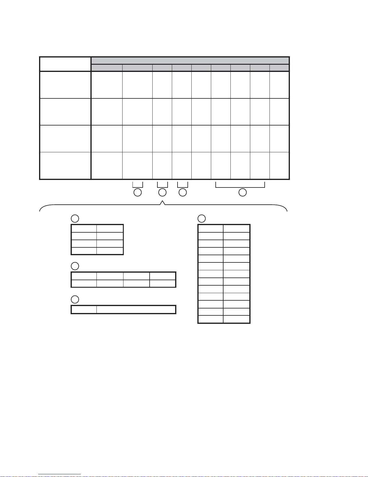
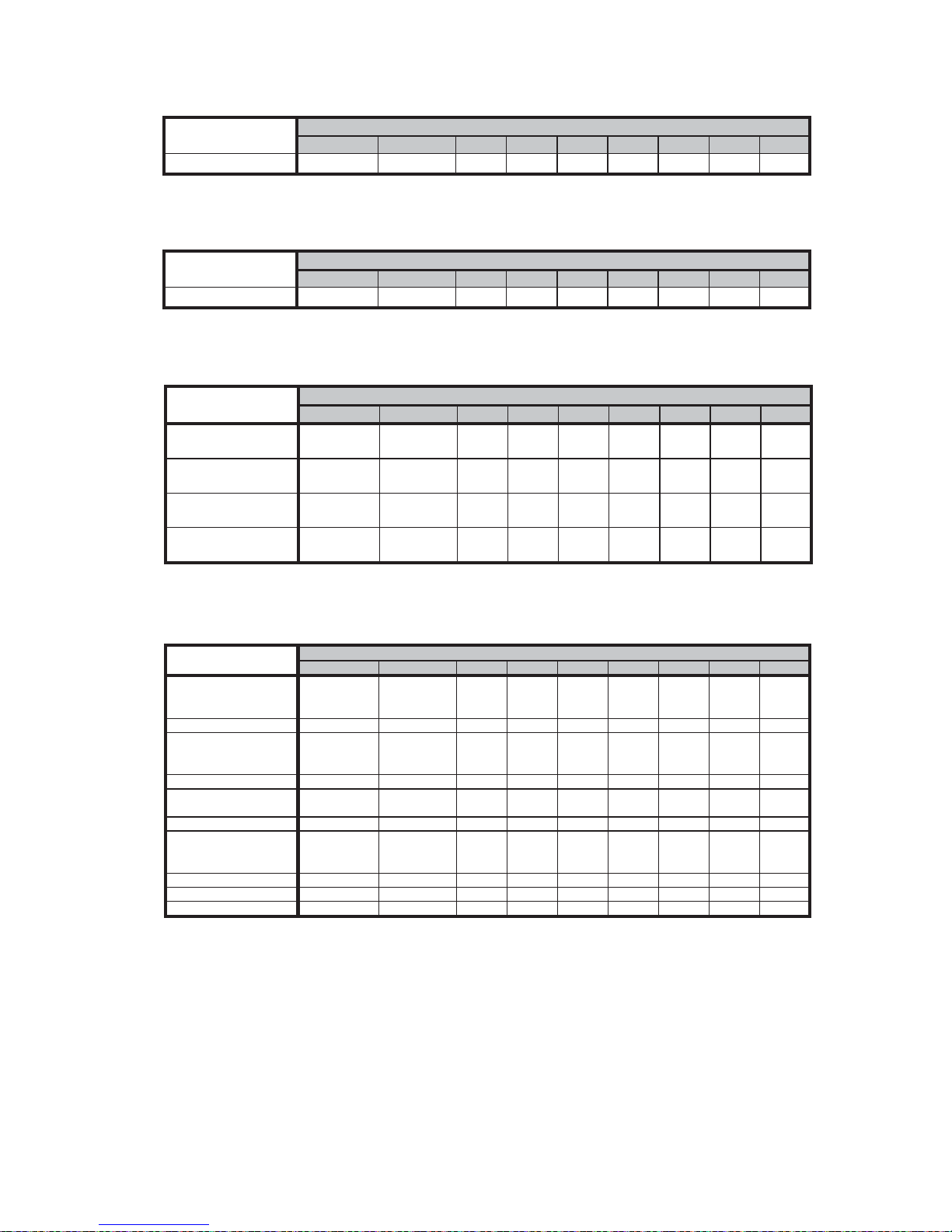
6.3. Service Mode Software Version Check Table
Some example of the actual FL display can be found in below table
POS 9 POS 8 POS 7 POS 6 POS 5 POS 4 POS 3 POS 2 POS 1
HTB880 with
software version 36
for Year 2014 (ROM
TYPE A)
4 CA 036
HTB580 with
software version 03
for Year 2014 (ROM
TYPE B)
4 CB 003
HTB680 with
software version 26
for Year 2014 (ROM
TYPE C)
4 CB 026
HTB480 with
software version 21
for Year 2014 (ROM
TYPE D)
4 CB 021
FL Display Position
Examples:
1 2 3 4
Sales Year
1 2011
2 2012
3 2013
4 2014
Range from 000 ~999
ROM Type
HTB880 HTB580 HTB680 HTB480
4CA 4CB 4CB 4CB
3
Running Version Number
XXX
4
1
Model Type
AHC
BXH
C HTB
D HTE
E HTF
F HTR
G HTX
HPM
I PMX
J AKX
K VKX
L
M
2
17
6.4. HDMI Version Display Table
6.5. Bluetooth Version Display Table
6.6. Service Mode Model Name Display Table
6.7. Service Mode Region Display Table
POS 9 POS 8 POS 7 POS 6 POS 5 POS 4 POS 3 POS 2 POS 1
HDMI Version
Display
H D M 0 050I
FL Display Position
POS 9 POS 8 POS 7 POS 6 POS 5 POS 4 POS 3 POS 2 POS 1
B T 011
Bluetooth Version
Display
FL Display Position
POS 9 POS 8 POS 7 POS 6 POS 5 POS 4 POS 3 POS 2 POS 1
For HTB880 display
HTB 880
For HTB680 display
HTB 680
For HTB580 display
HTB 580
For HTB480 display
HTB 480
FL Display Position
Exam
p
les:
POS 9 POS 8 POS 7 POS 6 POS 5 POS 4 POS 3 POS 2 POS 1
Display for
Europe/Russia
(
EB/EG/EE series
)
1:EUROPE
Reserve
2:RESV
Display for North
America region (P, PC,
PP series
)
3:US/C AN
Reserve
4:RESV
Display for Japan
re
g
ion
(
Do series
)
5:JAPAN
Reserve
6:RESV
Display for G/Other
(GN/GS/GT/PH/GK
series
)
7:G/OTHER
Reserve
8:RESV
Reserve
9:RESV
Reserve 10:RESV
Re
g
ion Displa
y
FL Display Position
18
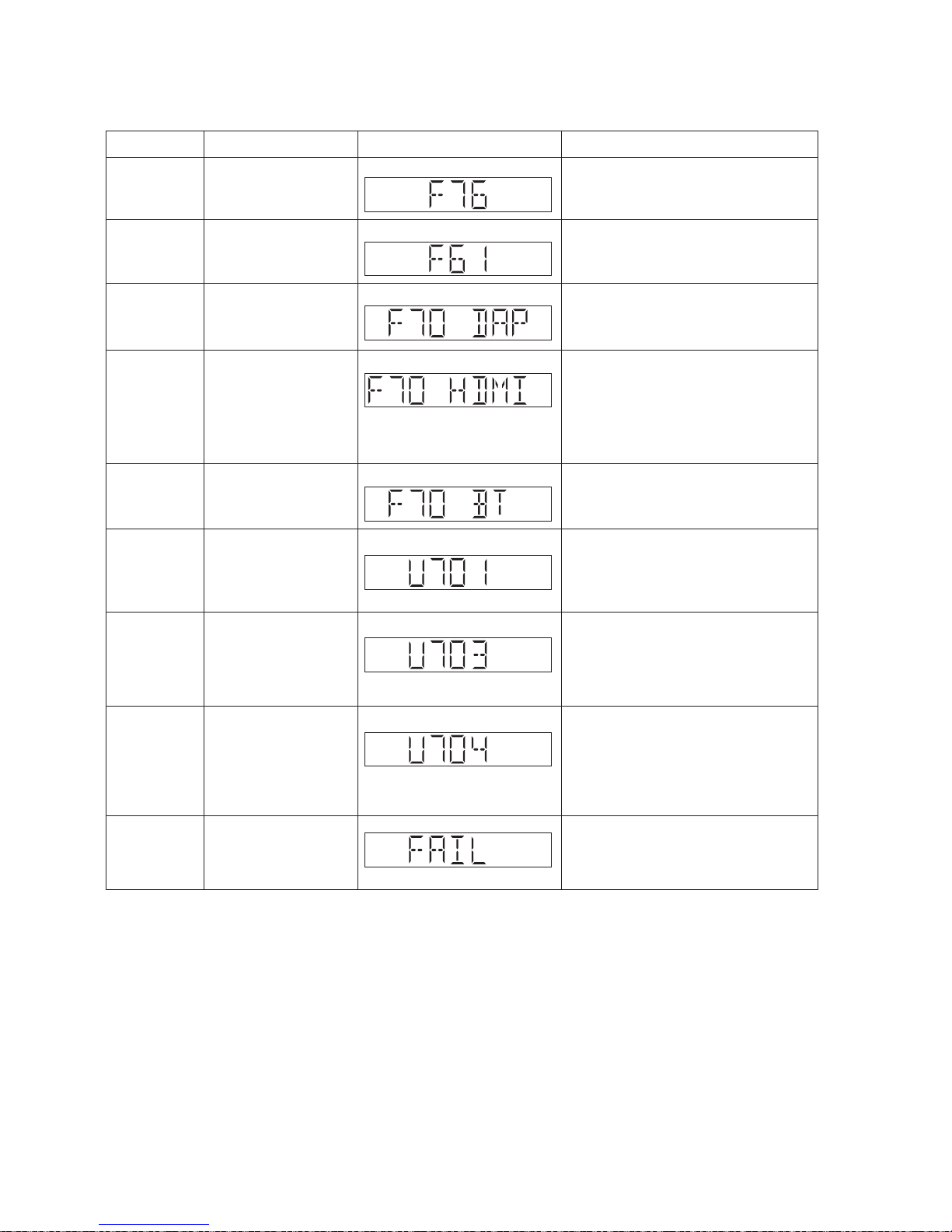
6.8. Service Function Error Code
FL display will also be able to display the Error Code of the respective model indicated in the table below
F76 Abnormality in the stabilized Power Supply
Power off the unit during
blinking.
F61 Power AMP Output Error
Power off the unit during
blinking.
F70 DAP Communication error between DAP module and
microprocessor
Blinking repeatedly
unless user power off.
Example:
Example:
Example:
Example:
F70 HDMI Communication error between HDMI Module
and microprocessor
HDMI Module broken and cannot communicate
with main microprocessor.
* I2C control line (no reply for 10 times)
* HDCP keys read error
Blinking repeatedly
unless user power off.
Example:
F70 BT Communication error between Bluetooth
Module and microprocessor
Blinking repeatedly
unless user power off.
Example:
U701 HDMI connection acts unusually
When HDMI IC cannot read TV HDCP register
from TV side or TV does not support HDCP.
* I2C error (usually no ACK)
Blinking repeatedly
unless user power off.
Example:
U703 HDMI connection acts unusually
Authentication Error.
* Bad receive BKSV
* Link verification mismatch
* Timed out waiting for downstream repeater
Blinking repeatedly
unless user power off.
Example:
U704 HDMI connection acts unusually
HDMI repeater receive unsupported video
format (resolution) from source device.
* Not support PC format - XVGA and cannot
support Vsync vertical frequency other than
60Hz/59.94Hz, 50Hz, 24Hz
Blinking repeatedly
unless user power off.
Error Code Description of error Automatic FL Display Diagnostic Contents
Example:
USB Update Fail USB updating of Software
Failed
Display Remained unless
user power off.

19
7 Troubleshooting Guide
This section is not available at the time of issue

20
8 Disassembly and Assembly Instructions
Caution Note:
• This section describes the disassembly and/or assembly procedures for all major printed circuit boards & main components for the unit. (You may refer to the section of “Main components and P.C.B Locations” as described in this service
manual)
• Before carrying out the disassembly process, please ensure all th e safety precautions & procedures are followed.
• During the disassembly and/or assembl y process, please handle with care as ther e may be chassis components with
sharp edges.
• Avoid touching heatsinks due to its high temperature after prolong use.
• Be sure to use proper service tools , equipments or jigs during repair.
• Select items from the following indexes when disassembly or replacement are required.
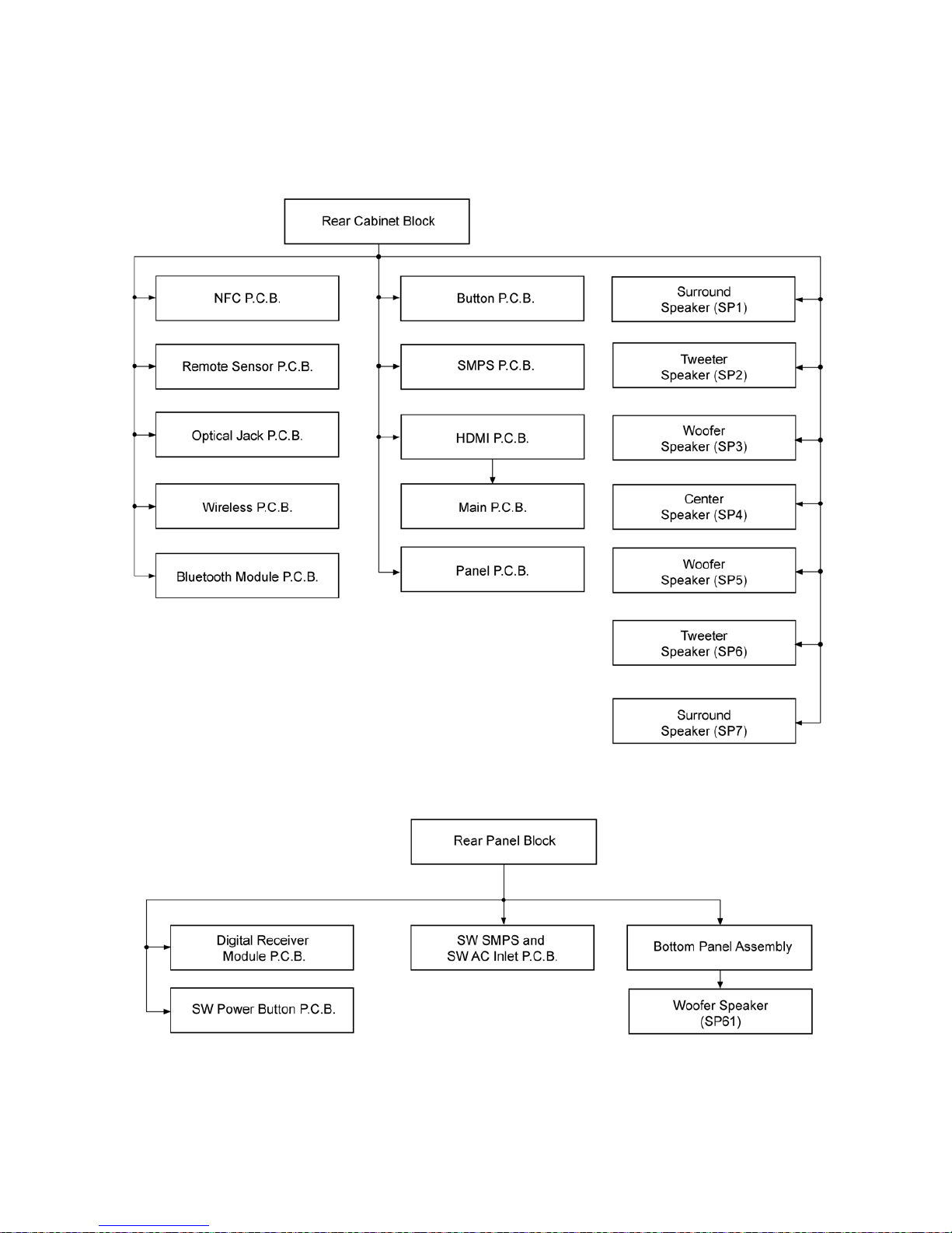
Disassembly of Main Unit (SU-HTB880)
• Disassembly of Rear Cabinet Block
• Disassembly of NFC P.C.B.
• Disassembly of Remote Sensor P.C.B.
• Disassembly of Optical Jack P.C.B.
• Disassembly of Wireless P.C.B.
• Disassembly of Bluetooth P.C.B.
• Disassembly of Button P.C.B.
• Disassembly of SMPS P.C.B.
• Disassembly of HDMI P.C.B.
• Disassembly of Main P.C.B.
• Disassembly of Panel P.C.B.
• Disassembly of Surround Speaker (SP1)
• Disassembly of Tweeter Speaker (SP2)
• Disassembly of Woofer Speaker (SP3)
• Disassembly of Center Speaker (SP4)
• Disassembly of Woofer Speaker (SP5)
• Disassembly of Tweeter Speaker (SP6)
• Disassembly of Surround Speaker (SP7)
Disassembly of Active Subwoofer (SB-HWA880)
• Disassembly of Rear Panel Block
• Disassembly of Digital Receiver Module P.C.B.
• Disassembly of SW Power Button P.C.B.
• Disassembly of SW SMPS and SW AC Inlet P.C.B.
• Disassembly of Bottom Panel Assembly
• Disassembly of Woofer Speaker (SP61)
8.1. Service Fixture & Tools
Prepare service tools before process service position.
Ref. No. Service Tools Remarks
SFT1 2P WIRE (SPK-SW DAMP) REXX1194 (2P Extension Cable) SB-HWA880
21
8.2. Disassembly flow chart
The following chart is the procedure for disassembling the casing and inside parts for internal inspection when carrying out the servicing.
To assemble the unit, reverse the steps shown in the chart below.
8.2.1. Main Unit (SU-HTB880)
8.2.2. Active Subwoofer (SB-HWA880)
22
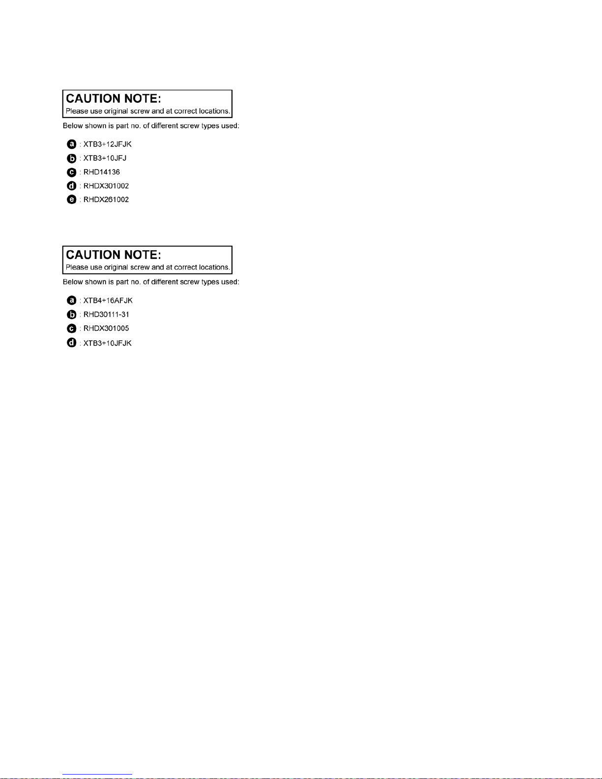
8.3. Type of Screws
8.3.1. Main Unit (SU-HTB880)
8.3.2. Active Subwoofer (SB-HWA880)
23
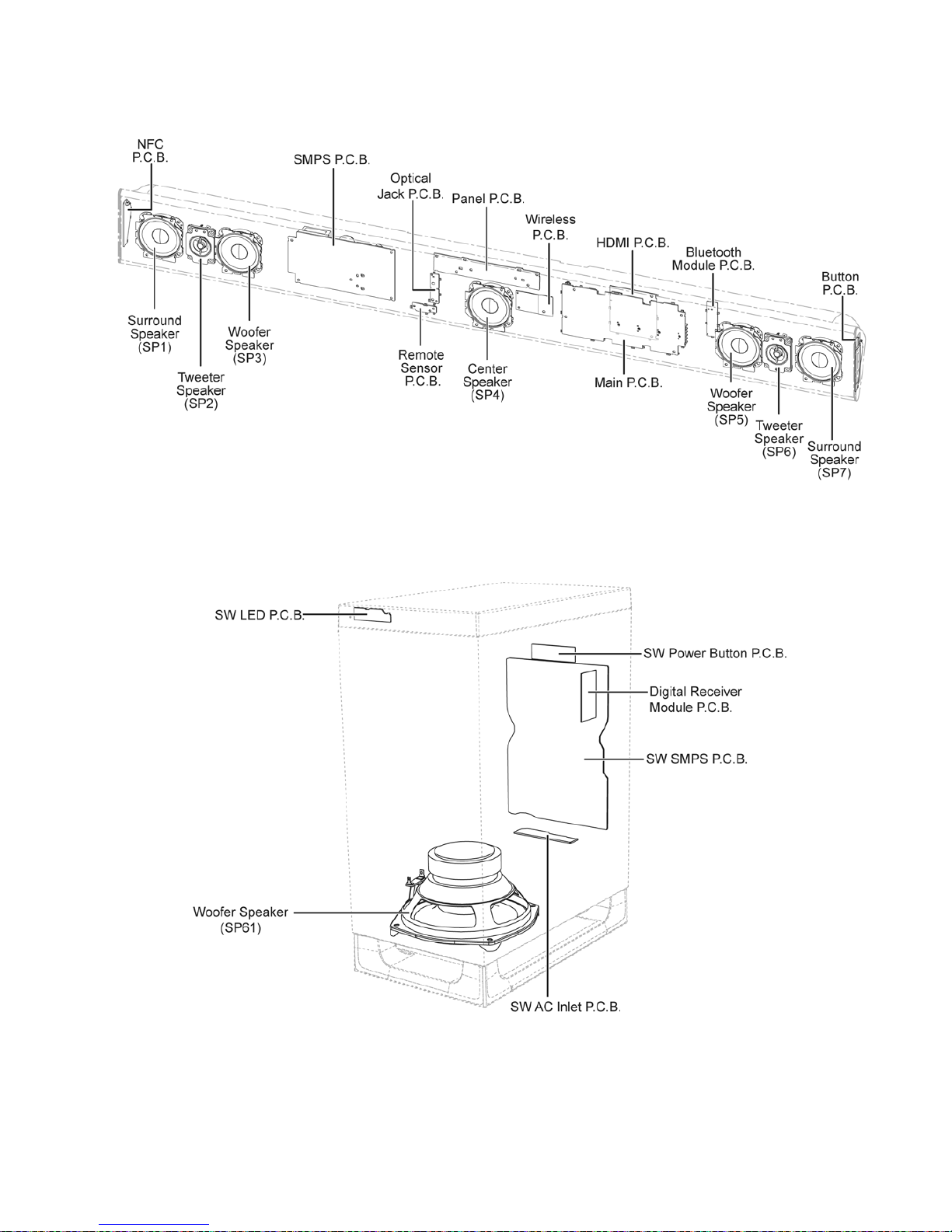
8.4. Main Parts Location Diagram
8.4.1. Main Unit (SU-HTB880)
8.4.2. Active Subwoofer (SB-HWA880)
24
8.5. Disassembly of Main Unit (SU-HTB880)
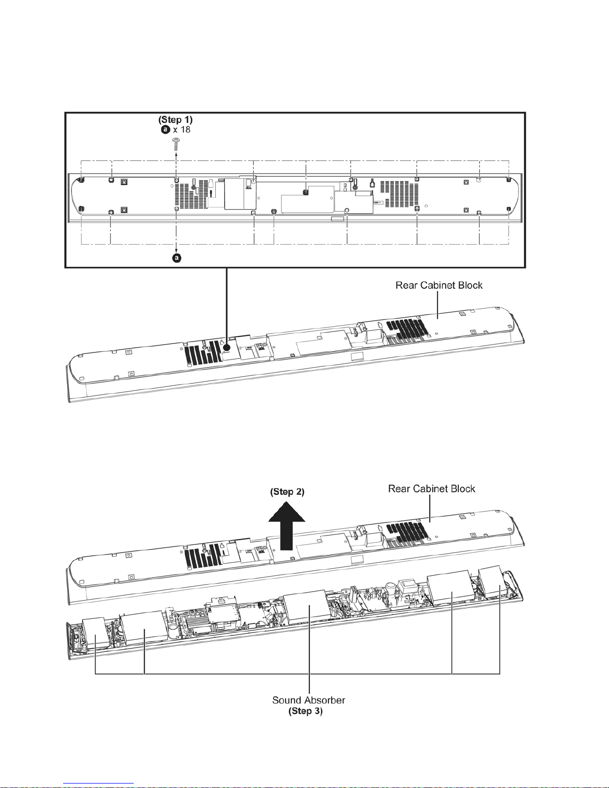
8.5.1. Disassembly of Rear Cabinet Block
Step 1 : Remove 18 screws.
Step 2 : Remove Rear Cabinet Block.
Caution : Do not exert too much force as it may damage the wiring within.
Step 3 : Remove Sound Absorber.
Caution : Safe keep the Sound Absorber and place it back during assembling.
25
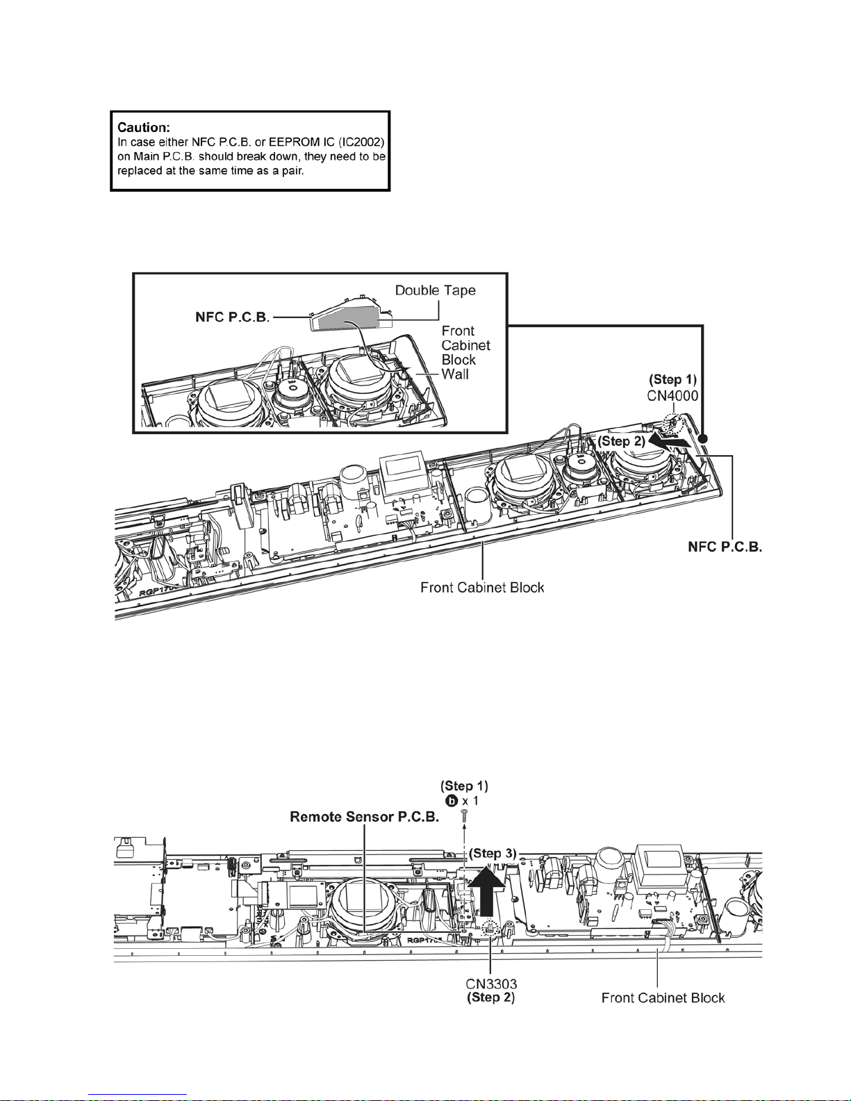
8.5.2. Disassembly of NFC P.C.B.
• Refer to “Disassembly of Rear Cabinet Block”.
Step 1 : Detach 3P wire at connector (CN4000) on NFC P.C.B..
Step 2 : Remove NFC P.C.B..
Caution : During assembly, ensure to push NFC P.C.B. to Front Cabinet Block Wall.
8.5.3. Disassembly of Remote Sensor P.C.B.
• Refer to “Disassembly of Rear Cabinet Block”.
•
Step 1 : Remove 1 screw.
Step 2 : Detach 3P wire at connector (CN3303) on Remote Sensor P.C.B..
Step 3 : Remove Remote Sensor P.C.B..
26
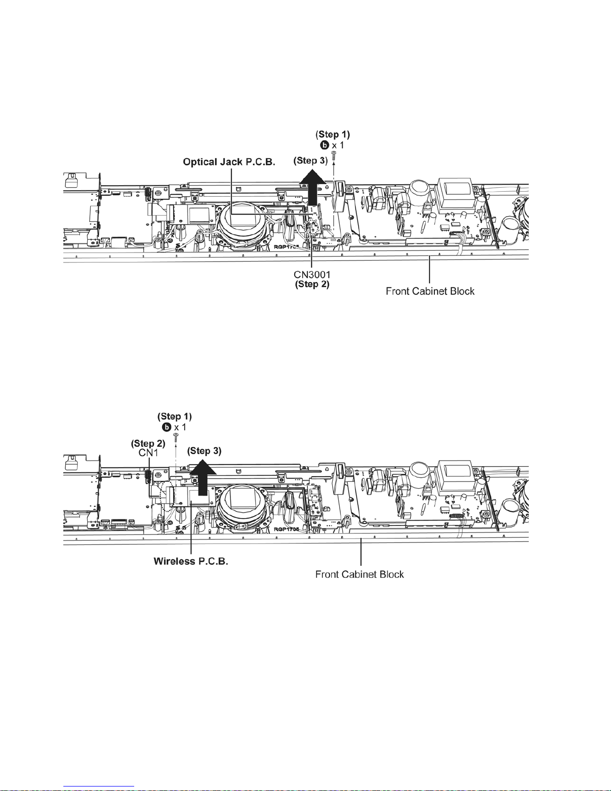
8.5.4. Disassembly of Optical Jack P.C.B.
• Refer to “Disassembly of Rear Cabinet Block”.
Step 1 : Remove 1 screw.
Step 2 : Detach 5P wire at connector (CN3001) on Optical Jack P.C.B..
Step 3 : Remove Optical Jack P.C.B..
8.5.5. Disassembly of Wireless P.C.B.
• Refer to “Disassembly of Rear Cabinet Block”.
Step 1 : Remove 1 screw.
Step 2 : Detach 24P FFC at connector (CN1) on Wireless P.C.B..
Step 3 : Remove Wireless P.C.B..

27
8.5.6. Disassembly of Bluetooth Module P.C.B.
• Refer to “Disassembly of Rear Cabinet Block”.
Step 1 : Remove 1 screw.
Step 2 : Detach 16P FFC at connector (CN1701) on Bluetooth Module P.C.B..
Step 3 : Remove Bluetooth Module P.C.B..
8.5.7. Disassembly of Button P.C.B.
• Refer to “Disassembly of Rear Cabinet Block”.
Step 1 : Detach 8P wire at connector (CN6103) on Button P.C.B..
Step 2 : Remove Button P.C.B..
Caution : During assembly, ensure to push Button P.C.B. to Front Cabinet Block Wall.
28
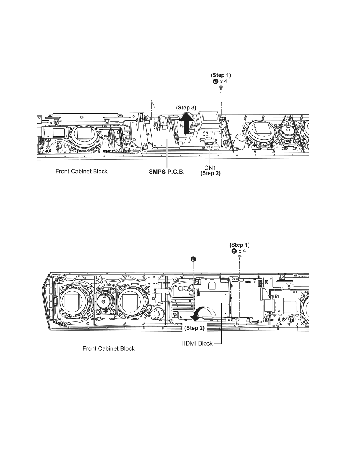
8.5.8. Disassembly of SMPS P.C.B.
• Refer to “Disassembly of Rear Cabinet Block”.
Step 1 : Remove 4 screws.
Step 2 : Detach 7P wire at connector (CN1) on SMPS P.C.B..
Step 3 : Remove SMPS P.C.B..
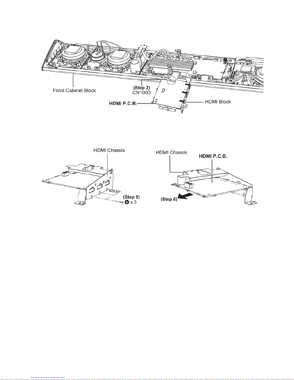
8.5.9. Disassembly of HDMI P.C.B.
• Refer to “Disassembly of Rear Cabinet Block”.
Step 1 : Remove 4 screws.
Step 2 : Upset HDMI Block.
29
Step 3 : Detach 30P FFC at connector (CN1000) on HDMI P.C.B..
Step 4 : Remove HDMI Block.
Step 5 : Remove 3 screws.
Step 6 : Remove HDMI P.C.B..
30
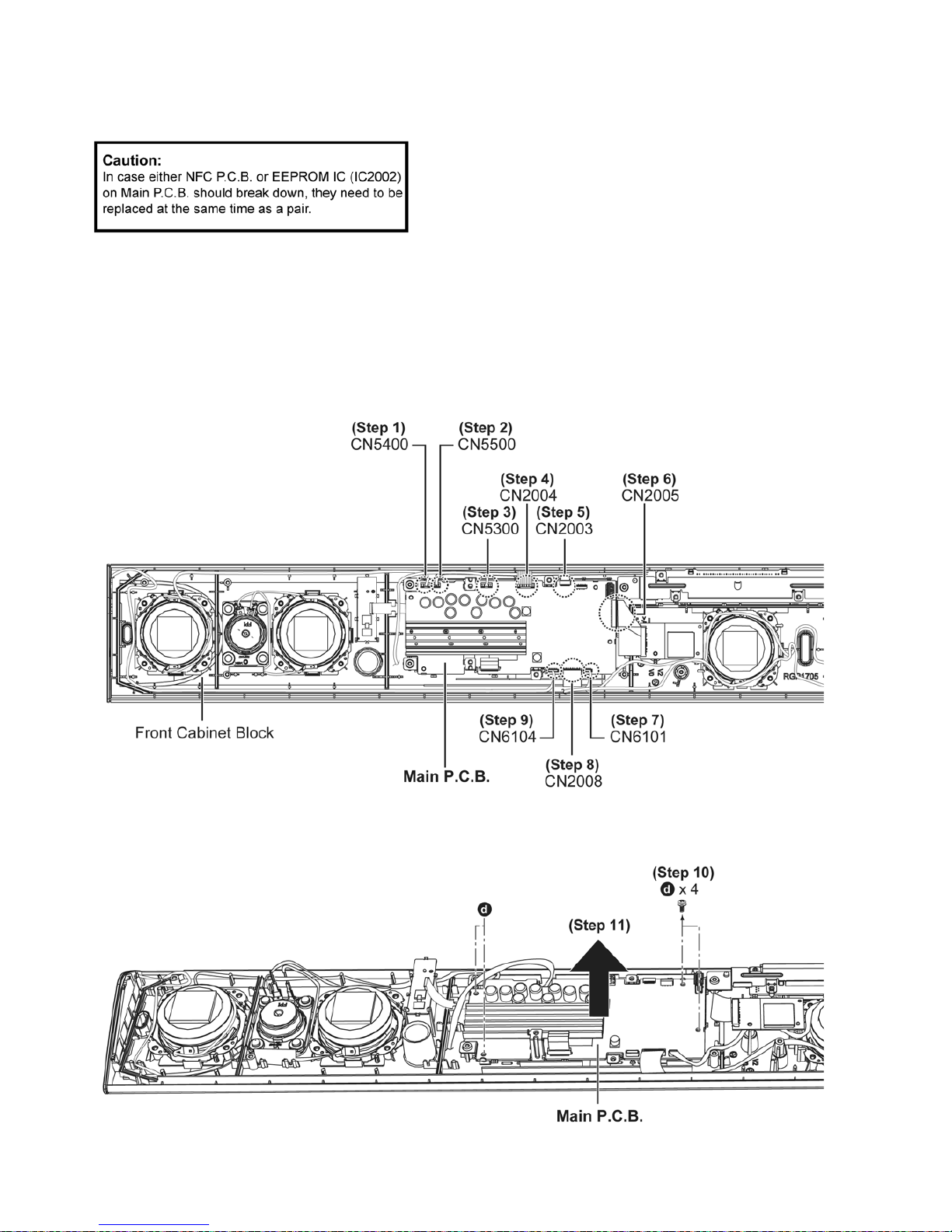
8.5.10. Disassembly of Main P.C.B.
• Refer to “Disassembly of Rear Cabinet Block”.
• Refer to (Step 1) - (Step 4) of item 8.5.9.
Step 1 : Detach 4P wire at connector (CN5400) on Main P.C.B..
Step 2 : Detach 2P wire at connector (CN5500) on Main P.C.B..
Step 3 : Detach 4P wire at connector (CN5300) on Main P.C.B..
Step 4 : Detach 7P wire at connector (CN2004) on Main P.C.B..
Step 5 : Detach 16P FFC at connector (CN2003) on Main P.C.B..
Step 6 : Detach 24P FFC at connector (CN2005) on Main P.C.B..
Step 7 : Detach 5P wire at connector (CN6101) on Main P.C.B..
Step 8 : Detach 15P FFC at connector (CN2008) on Main P.C.B..
Step 9 : Detach 8P wire at connector (CN6104) on Main P.C.B..
Step 10 : Remove 4 screws.
Step 11 : Remove Main P.C.B..
 Loading...