

Panasonic SU-HTB550PH, SB-HTB550P, SB-HWA520PH, SC-HTB550PH Service Manual
© Panasonic Corporation 2012. All rights reserved.
Unauthorized copying and distribution is a violation of
law.
PSG1204036AE
Home Theater Audio System
Model No. SU-HTB550PH
SB-HTB550P
SB-HWA520PH
SC-HTB550PH
Product Color: (K)...Black Type
TABLE OF CONTENTS
PAG E PAG E
1 Safety Precautions ----------------------------------------------- 3
1.1. General Guidelines---------------------------------------- 3
1.2. Before Repair and Adjustment ------------------------- 4
1.3. Protection Circuitry ---------------------------------------- 4
1.4. Caution For Fuse Replacement------------------------ 4
1.5. Caution For SMPS Module------------------------------ 4
1.6. Safety Part Information----------------------------------- 5
1.7. Safety Installation Instructions -------------------------6
2Warning--------------------------------------------------------------7
2.1. Prevention of Electro Static Discharge (ESD)
to Electrostatically Sensitive (ES) Devices ----------7
2.2. Service caution based on Legal restrictions --------8
3 Service Navigation ----------------------------------------------- 9
3.1. Service Information ----------------------------------------9
Note: Please use this manual together with service manual
Model No.[SC-HTB550PCK, Order No.PSG1202001CE].

2
3.2. Notes -------------------------------------------------------- 10
3.3. Different Points ------------------------------------------- 11
4 Specifications ---------------------------------------------------- 14
5 Block Diagram --------------------------------------------------- 15
5.1. Main Unit (SU-HTB550) -------------------------------- 15
5.2. Active Subwoofer (SB-HWA520)---------------------19
6 Schematic Diagram--------------------------------------------- 20
6.1. Main Unit (SU-HTB550) -------------------------------- 20
6.2. Active Subwoofer (SB-HWA520)---------------------26
7 Printed Circuit Board ------------------------------------------ 29
7.1. Main Unit (SU-HTB550) ------------------------------- 29
7.2. Active Subwoofer (SB-HWA520)---------------------33
8 Exploded View and Replacement Parts List ----------- 34
8.1. Exploded View and Mechanical replacement
Parts List --------------------------------------------------- 34
8.2. Electrical Replacement Parts List -------------------- 41
3
1 Safety Precautions
1.1. General Guidelines
1. When servicing, observe the original lead dress. If a short circuit is found, replace all parts which have been overheated or
damaged by the short circuit.
2. After servicing, ensure that all the protective devices such as insulation barriers, insulation papers shields are properly
installed.
3. After servicing, check for leakage current checks to prevent from being exposed to shock hazards.
1.1.1. Leakage Current Cold Check
1. Unplug the AC cord and connect a jumper between the two prongs on the plug.
2. Using an ohmmeter measure the resistance value, between the jumpered AC plug and each exposed metallic cabinet part on
the equipment such as screwheads, connectors, control shafts, etc. When the exposed metallic part has a return path to the
chassis, the reading should be between 1MΩ and 5.2Ω. When the exposed metal does not have a return path to the chassis,
the reading must be
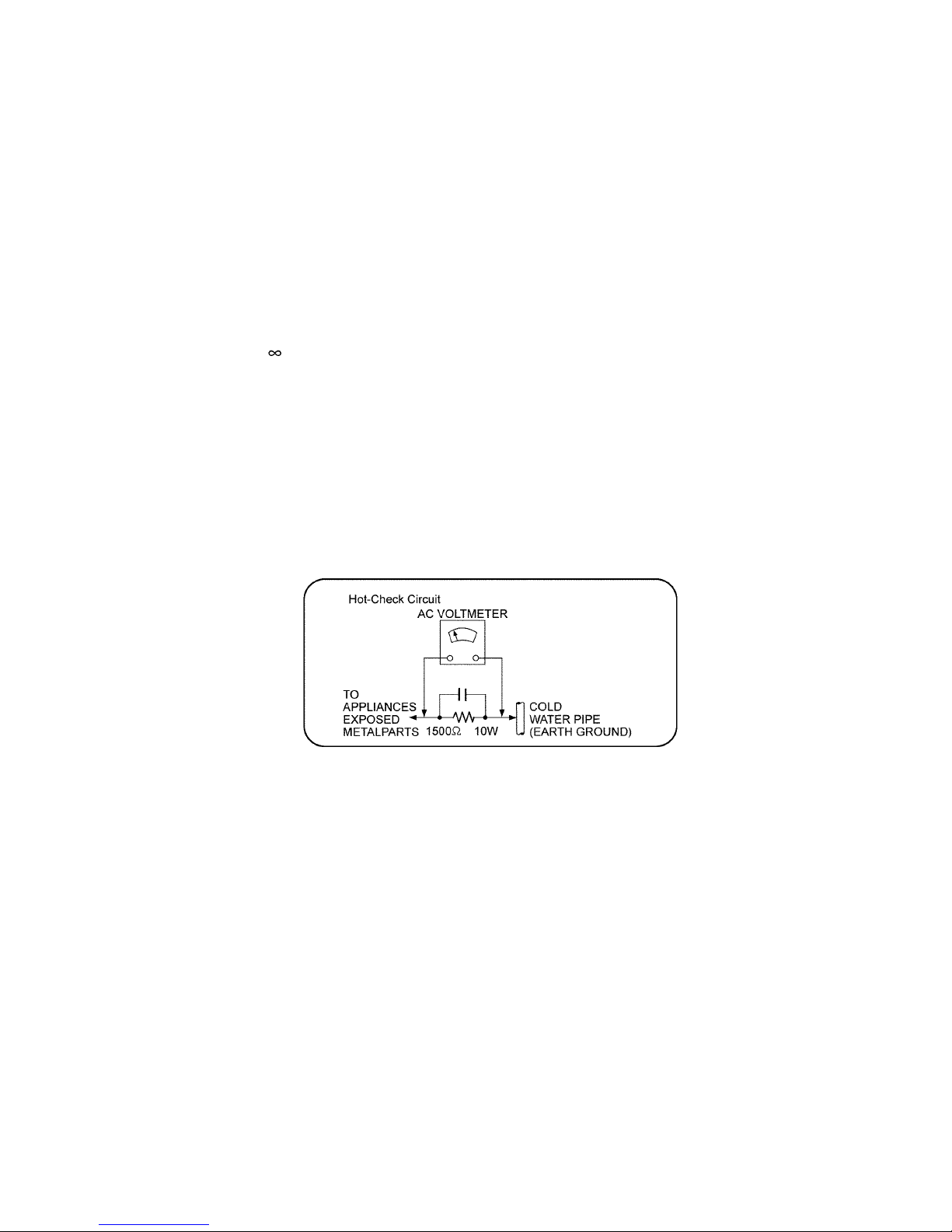
1.1.2. Leakage Current Hot Check
1. Plug the AC cord directly into the AC outlet. Do not use an isolation transformer for this check.
2. Connect a 1.5kΩ, 10 watts resistor, in parallel with a 0.15μF capacitors, between each exposed metallic part on the set and a
good earth ground such as a water pipe, as shown in Figure 1.
3. Use an AC voltmeter, with 1000 ohms/volt or more sensitivity, to measure the potential across the resistor.
4. Check each exposed metallic part, and measure the voltage at each point.
5. Reverse the AC plug in the AC outlet and repeat each of the above measurements.
6. The potential at any point should not exceed 0.75 volts RMS. A leakage current tester (Simpson Model 229 or equivalent)
may be used to make the hot checks, leakage current must not exceed 1/2 milliamp. should the measurement is outside of
the limits specified, there is a possibility of a shock hazard, and the equipment should be repaired and re-checked before it is
returned to the customer.
4
1.2. Before Repair and Adjustment
Main Unit (SU-HTB550)
Disconnect AC power, discharge unit AC Capacitors as such C5700, C5701, C5702, C5703 and C5705 through a 10W, 1W resistor
to ground.
Caution : DO NOT SHORT-CIRCUIT DIRECTLY (with a screwdriver blade, for instance), as this may destroy solid state devices.
After repairs are completed, restore power gradually using a variac, to avoid overcurrent.
• Current consumption AC 110 V to 240 V, 50/60 Hz in Power On, No signal, Volume minimum, SEL: HDMI/OPT mode should be
~180 mA.
Active Subwoofer (SB-HWA520)
Caution : DO NOT SHORT-CIRCUIT DIRECTLY (with a screwdriver blade, for instance), as this may destroy solid state devices.
After repairs are completed, restore power gradually using a variac, to avoid overcurrent.
• Current consumption at AC 110 V to 240 V, 50/60 Hz in Power On link, Volume minimum, SEL: DVD mode should be ~220 mA.
1.3. Protection Circuitry
The protection circuitry may have operated if either of the following conditions are noticed:
• No sound is heard when the power is turned on.
• Sound stops during a performance.
The function of this circuitry is to prevent circuitry damage if, for example, the positive and negative speaker connection wires are
"shorted", or if speaker systems with an impedance less than the indicated rated impedance of the amplifier are used.
If this occurs, follow the procedure outlines below:
1. Turn off the power.
2. Determine the cause of the problem and correct it.
3. Turn on the power once again after one minute.
Note:
When the protection circuitry functions, the unit will not operate unless the power is first turned off and then on again.
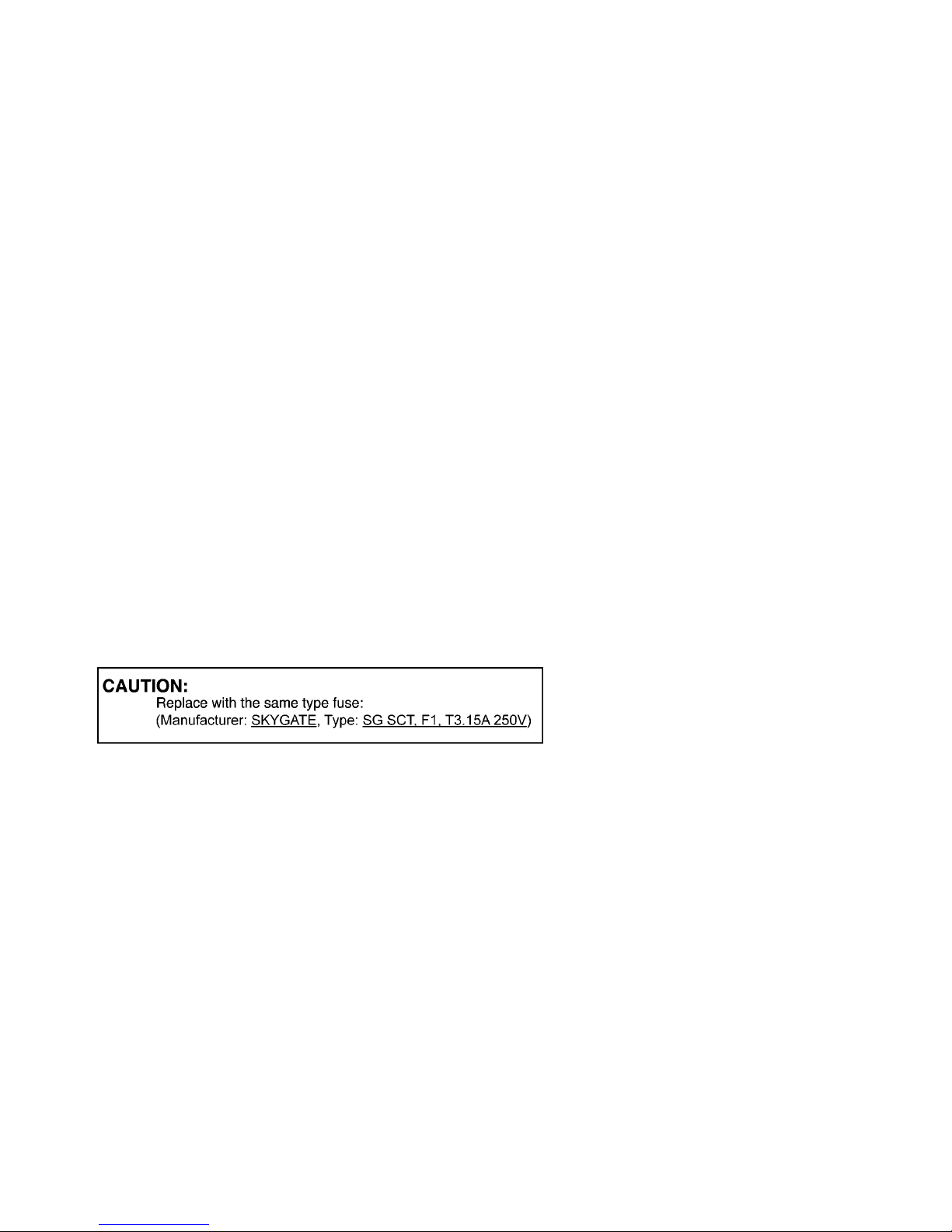
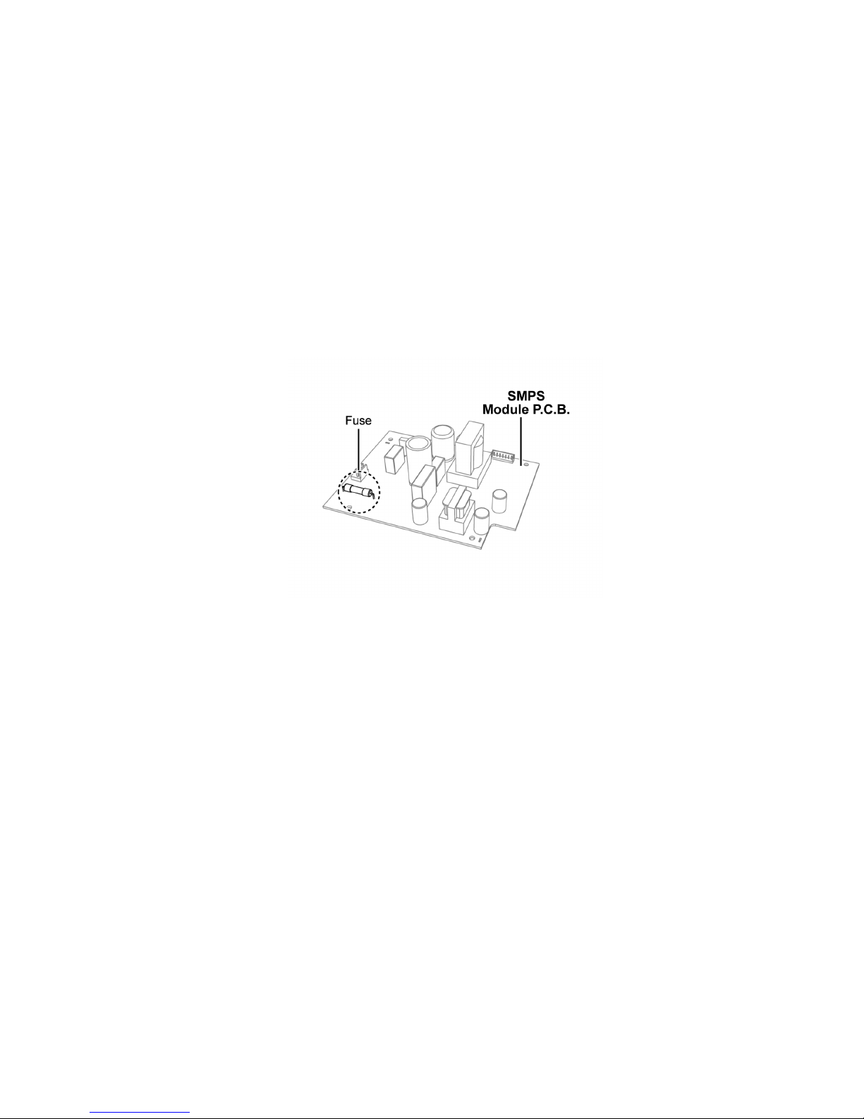
1.4. Caution For Fuse Replacement
1.4.1. SU-HTB550
1.5. Caution For SMPS Module
Caution:
Active Subwoofer (SB-HWA520) uses SMPS Module to supply the voltage & power required for the circuitries. It is
replaced as an assembly, do not attempt to replace or repair by individual components.
5
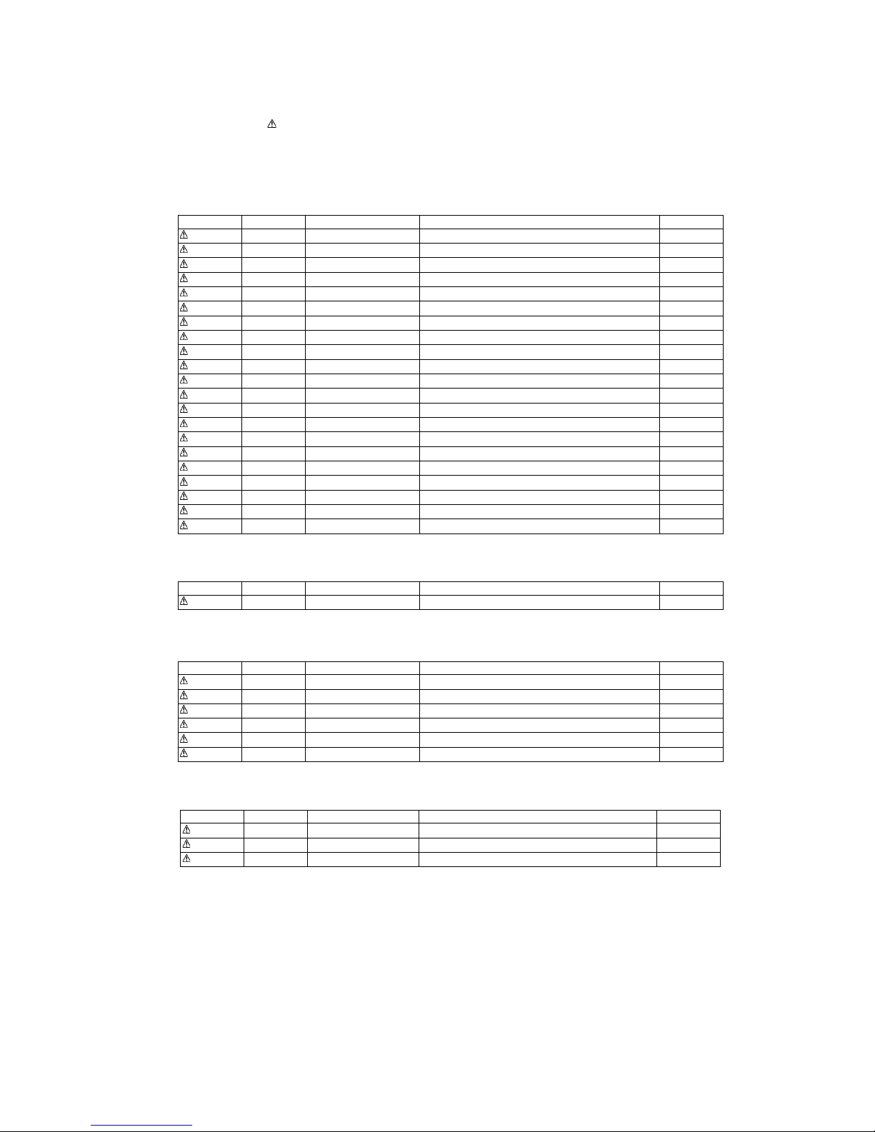
1.6. Safety Part Information
Safety Parts List:
There are special components used in this equipment which are important for safety.
These parts are marked by in the Schematic Diagrams & Replacement Parts List. It is essential that these critical parts should
be replaced with manufacturer’s specified parts to prevent shock, fire or other hazards. Do not modify the original design without
permission of manufacturer.
1.6.1. Main Unit (SU-HTB550)
1.6.2. Front Speaker (SB-HTB550)
1.6.3. Active Subwoofer (SB-HWA520)
1.6.4. System (SC-HTB550)
Safety Ref. No. Part No. Part Name & Description Remarks
11 RGR0423B-G REAR PANEL
27 RMZ1264 SMPS INSULATOR BOTTOM
28 RFKKUHTB350P TOP PANEL ASS’Y
PCB7 REP4737NA SMPS P.C.B.
DZ5701 ERZV10V511CS ZNR
L5702 ELF19H820E LINE FILTER
L5703 ELF19H010A LINE FILTER
T5701 ETS35BL166AD MAIN TRANSFORMER
PC5720 B3PBA0000503 PHOTO COUPLER
PC5760 B3PBA0000503 PHOTO COUPLER
F1 K5G312Y00007 FUSE PROTECTOR
TH5702 D4CAA5R10001 THERMISTOR
P5701 K2AA2B000011 AC INLET
R5700 ERJ8GEYJ105V 1M 1/4W
R5701 ERJ8GEYJ105V 1M 1/4W
R5710 ERJ8GEYJ105V 1M 1/4W
C5700 F1BAF471A013 470pF
C5701 F0CAF104A105 0.1uF
C5702 F0CAF104A105 0.1uF
C5703 F0CAF104A105 0.1uF
C5705 F1BAF471A013 470pF
Safety Ref. No. Part No. Part Name & Description Remarks
3 RYQ0955-K REAR CABINET ASSY
Safety Ref. No. Part No. Part Name & Description Remarks
66 RGN3230-K SPEC LABEL
70 REEX1265-J 2P WIRE (SMPS MODULE - AC INLET)
PCB14 REP4806BD AC INLET P.C.B. (RTL)
PCB15 N0AE3ZJ00001 SMPS MODULE P.C.B.
PCB16 REP4814A DIGITAL RECEIVER MODULE P.C.B.
P5701 K2AAYA000001 AC INLET
Safety Ref. No. Part No. Part Name & Description Remarks
A1 N2QAYC000064 REMOTE CONTROL
A2 K2CJ2DA00008 AC CORD
A3 RQT9668-1M O/I BOOK (Sp/Pr)
6
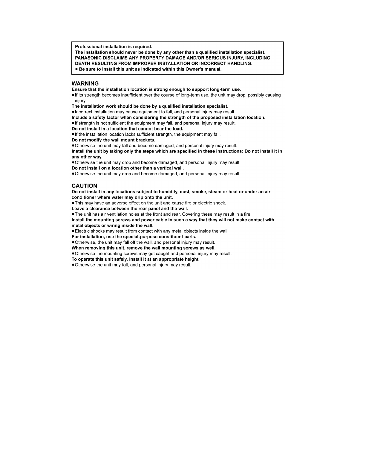
1.7. Safety Installation Instructions

7
2Warning
2.1. Prevention of Electro Static Discharge (ESD) to Electrostatically Sensitive (ES) Devices
Some semiconductor (solid state) devices can be damaged easily by electricity. Such components commonly are called Electrostatically Sensitive (ES) Devices. Examples of typical ES devices are integrated circuits and some field-effect transistors and semiconductor “chip” components. The following techniques should be used to help reduce the incidence of component damage caused by
electro static discharge (ESD).
1. Immediately before handling any semiconductor component or semiconductor-equiped assembly, drain off any ESD on your
body by touching a known earth ground. Alternatively, obtain and wear a commercially available discharging ESD wrist strap,
which should be removed for potential shock reasons prior to applying power to the unit under test.
2. After removing an electrical assembly equiped with ES devices, place the assembly on a conductive surface such as aluminium foil, to prevent electrostatic charge build up or exposure of the assembly.
3. Use only a grounded-tip soldering iron to solder or unsolder ES devices.
4. Use only an anti-static solder remover device. Some solder removal devices not classified as “anti-static (ESD protected)” can
generate electrical charge to damage ES devices.
5. Do not use freon-propelled chemicals. These can generate electrical charges sufficient to damage ES devices.
6. Do not remove a replacement ES device from its protective package until immediately before you are ready to install it. (Most
replacement ES devices are packaged with leads electrically shorted together by conductive foam, aluminium foil or comparable conductive material).
7. Immediately before removing the protective material from the leads of a replacement ES device, touch the protective material
to the chassis or circuit assembly into which the device will be installed.
Caution
Be sure no power is applied to the chassis or circuit, and observe all other safety precautions.
8. Minimize body motions when handling unpackaged replacement ES devices. (Otherwise harmless motion such as the brushing together of your clothes fabric or the lifting of your foot from a carpeted floor can generate static electricity (ESD) sufficient
to damage an ES device).
8
2.2. Service caution based on Legal restrictions
2.2.1. General description about Lead Free Solder (PbF)
The lead free solder has been used in the mounting process of all electrical components on the printed circuit boards used for this
equipment in considering the globally environmental conservation.
The normal solder is the alloy of tin (Sn) and lead (Pb). On the other hand, the lead free solder is the alloy mainly consists of tin
(Sn), silver (Ag) and Copper (Cu), and the melting point of the lead free solder is higher approx.30 degrees C (86°F) more than that
of the normal solder.
Definition of PCB Lead Free Solder being used
Service caution for repair work using Lead Free Solder (PbF)
• The lead free solder has to be used when repairing the equipment for which the lead free solder is used.
(Definition: The letter of “PbF” is printed on the PCB using the lead free solder.)
• To put lead free solder, it should be well molten and mixed with the original lead free solder.
• Remove the remaining lead free solder on the PCB cleanly for soldering of the new IC.
• Since the melting point of the lead free solder is higher than that of the normal lead solder, it takes the longer time to melt the
lead free solder.
• Use the soldering iron (more than 70W) equipped with the temperature control after setting the temperature at 350±30 degrees
C (662±86°F).
Recommended Lead Free Solder (Service Parts Route.)
• The following 3 types of lead free solder are available through the service parts route.
RFKZ03D01K-----------(0.3mm 100g Reel)
RFKZ06D01K-----------(0.6mm 100g Reel)
RFKZ10D01K-----------(1.0mm 100g Reel)
Note
* Ingredient: Tin (Sn), 96.5%, Silver (Ag) 3.0%, Copper (Cu) 0.5%, Cobalt (Co) / Germanium (Ge) 0.1 to 0.3%
The letter of “PbF” is printed either foil side or components side on the PCB using the lead free solder.
(See right figure)
9
3 Service Navigation
3.1. Service Information
This service manual contains technical information which will allow service personnel’s to understand and service this model.
Please place orders using the parts list and not the drawing reference numbers.
If the circuit is changed or modified, this information will be followed by supplement service manual to be filed with original service
manual.
• Microprocessor :
The following components are supplied as an assembled part.
• Microprocessor IC, IC2301 (RFKWMHTB550P).
• SMPS Module :
Active Subwoofer (SB-HWA520) uses SMPS Module to supply the voltage & power required for the circuitries. It is
replaced as an assembly, do not attempt to replace or repair by individual components.
• Bluetooth Module :
Bluetooth feature is not applicable in this model.

10
3.2. Notes
This service manual contains technical information which will allow service personnel’s to understand and service this model.
Please place orders using the parts list and not the drawing reference numbers.
If the circuit is changed or modified, this information will be followed by supplement service manual to be filed with original service
manual.
1) This service manual does not contains the following information
This simplified service manual is base on SC-HTB550PCK. Please refer to the original service manual, SC-HTB550PCK (Order No.
PSG1202001CE) for the below mention contents.
- Location of Controls and Components
- Operating Instructions
- Self Diagnostic and Doctor Mode Setting
- Disassembly and Assembly Instructions
- Service Position
- Voltage Measurement & Waveform Chart
- Overall Simplified Block
- Block Diagram
- Wiring Connection Diagram
- Schematic Diagram
- Printed Circuit Board
- Illustration of IC’s, Transistors and Diodes
- Terminal Function of IC’s
2) This service manual contains include the following information
- Safety Precautions
- Warning
- Service Navigation
- Specifications
- Block Diagram
- Schematic Diagram
- Printed Circuit Board
- Exploded View and Replacement Parts List

11
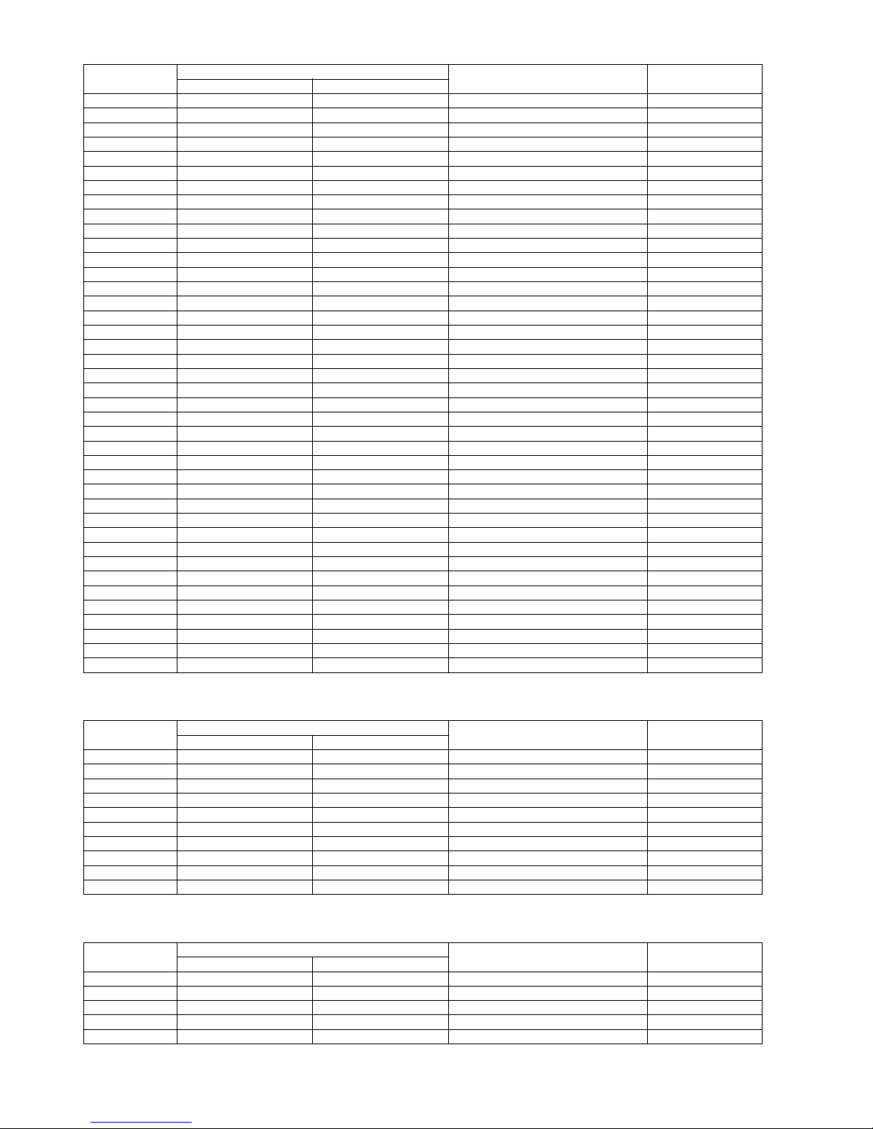
3.3. Different Points
3.3.1. Main Unit (SU-HTB550)
Ref. No. Parts No. Parts name & Description Remarks
SU-HTB550PCK SU-HTB550PHK
11 RGR0423B-B2 RGR0423B-G REAR PANEL
12 RYP1694-K RYP1694D-K FRONT PANEL ASSY
13 RGU2775-K RGU2775-K1 VOLUME BUTTON
C2101 F1G1H101A565 _ 100pF 50V
C2102 F1G1H101A565 _ 100pF 50V
C2105 F1G0J105A031 _ 1uF 6.3V
C2106 F1G0J105A031 _ 1uF 6.3V
C2107 F1J1A106A043 _ 10uF 10V
C2108 F1J1A106A043 _ 10uF 10V
C2109 F1J1A106A043 _ 10uF 10V
C2110 F1J1A106A043 _ 10uF 10V
C2111 F1G1H101A565 _ 100pF 50V
C2112 F1G1H101A565 _ 100pF 50V
C2113 F1G1A1040006 _ 0.1uF 10V
C2114 F1J1A106A043 _ 10uF 10V
C2115 F1G1A1040006 _ 0.1uF 10V
C2116 F1J1A106A043 _ 10uF 10V
C2117 F1G1A1040006 _ 0.1uF 10V
C2118 F1J1A106A043 _ 10uF 10V
C2119 EEEHB0J101UR _ 100uF 6.3V
C2120 F1G1A1040006 _ 0.1uF 10V
C5700 F1BAF1020020 F1BAF471A013 470pF
C5705 F1BAF1020020 F1BAF471A013 470pF
C5712 F2B2D1810007 F2A2G1810002 180uF 400V
CN2111 K1MY12AA0021 _ 12P CONNECTOR
D6008 B3AEA0000166 _ DIODE
DZ5701 ERZVA5Z471 ERZV10V511CS ZNR
IC2101 C0ABBA000159 _ IC
IC2102 C0FBAK000026 _ IC
IC2103 C0JBAR000396 _ IC
IC5701 C0DABYY00035 C0DAAYY00064 IC
K100 D0GBR00JA008 _ 0 1/10W
K101 - D0GBR00JA008 0 1/10W
K111 D0GAR00J0008 _ 0 1/16W
K113 _ D0GAR00J0008 0 1/16W
K211 D0GAR00J0008 _ 0 1/16W
K213 _ D0GAR00J0008 0 1/16W
K5722 ERJ3GEY0R00V _ 0 1/10W
K5724 _ ERJ3GEY0R00V 0 1/10W
L2805 G1C330MA0291 G1C330M00028 INDUCTOR
L5702 _ ELF19H820E LINE FILTER
LB2101 J0JYB0000013 _ INDUCTOR
LB2102 J0JYB0000013 _ INDUCTOR
LB2103 J0JBC0000014 _ INDUCTOR
LB2104 J0JBC0000014 _ INDUCTOR
LB2105 J0JBC0000014 _ INDUCTOR
LB2106 J0JHC0000078 _ INDUCTOR
P5701 K2AB2B000007 K2AA2B000011 AC INLET
PCB1 REP4735E REP4735D MAIN P.C.B. (RTL)
PCB3 REP4792AA REP4792BA PANEL P.C.B. (RTL)
PCB4 REP4792AB REP4792BB BUTTON P.C.B. (RTL)
PCB5 REP4792AC REP4792BC POWER BUTTON P.C.B. (RTL)
PCB6 REP4792AD REP4792BD WIRELESS ADAPTER P.C.B. (RTL)
PCB7 REP4737LA REP4737NA SMPS P.C.B. (RTL)
PCB8 REP4777A REP4813A DIGITAL TRANSMITTER MODULE
P. C .B .
PCB9 REP4805A - BLUETOOTH MODULE P.C.B.
R2101 ERJ2GEJ104X _ 100K 1/16W
R2103 ERJ2GEJ223X _ 22K 1/16W
R2104 ERJ2GEJ223X _ 22K 1/16W
R2105 ERJ2GEJ223X _ 22K 1/16W
12
3.3.2. Active Subwoofer (SB-HWA520)
3.3.3. System (SC-HTB550)
R2106 ERJ2GEJ223X _ 22K 1/16W
R2107 ERJ2GEJ154X _ 150K 1/16W
R2108 ERJ2GEJ154X _ 150K 1/16W
R2109 ERJ2GEJ154X _ 150K 1/16W
R2110 ERJ2GEJ154X _ 150K 1/16W
R2111 ERJ2GEJ472X _ 4.7K 1/16W
R2112 ERJ2GEJ472X _ 4.7K 1/16W
R2113 ERJ2GEJ101X _ 100 1/16W
R2114 ERJ2GEJ101X _ 100 1/16W
R2115 ERJ2GEJ473X _ 47K 1/16W
R2116 ERJ2GEJ473X _ 47K 1/16W
R2117 ERJ2GEJ100X _ 10 1/16W
R2118 ERJ2GEJ330X _ 33 1/16W
R2119 _ D0GAR00J0008 0 1/16W
R2121 ERJ2GEJ330X _ 33 1/16W
R2124 ERJ2GEJ330X _ 33 1/16W
R2125 ERJ2GEJ330X _ 33 1/16W
R2126 ERJ2GEJ102X _ 1K 1/16W
R2127 ERJ2GEJ102X _ 1K 1/16W
R2128 ERJ2GEJ102X _ 1K 1/16W
R2227 ERJ2GEJ101X _ 100 1/16W
R2228 ERJ2GEJ101X _ 100 1/16W
R2229 ERJ2GEJ472X _ 4.7K 1/16W
R2281 ERJ2GEJ104X ERJ2GEJ473X 47K 1/16W
R2338 ERJ2GEJ101X _ 100 1/16W
R2343 ERJ2GEJ101X _ 100 1/16W
R5700 ERJ8GEYJ155V ERJ8GEYJ105V 1M 1/4W
R5701 ERJ8GEYJ155V ERJ8GEYJ105V 1M 1/4W
R5702 ERJ1TYJ333U ERJ1TYJ104U 100K 1W
R5703 ERJ1TYJ333U ERJ1TYJ104U 100K 1W
R5710 ERJ8GEYJ155V ERJ8GEYJ105V 1M 1/4W
R5727 ERX2SZJR15P ERX2SZJR18P 0.18 2W
R5761 _ ERJ3GEYJ824V 820K 1/10W
R5802 ERJ3RBD153V ERJ3RBD332V 3.3K 1/16W
R5817 ERJ3RBD562V ERJ3RBD222V 2.2K 1/16W
R5818 ERJ3GEYJ391V ERJ3RBD222V 2.2K 1/16W
R5819 ERJ6GEYJ122V ERJ3GEYJ151V 150 1/10W
R6016 D0GB152JA008 _ 1.5K 1/10W
T5701 ETS35BC2ZGAD ETS35BL166AD MAIN TRANSFORMER
TH5702 D4CAA2R20001 D4CAA5R10001 THERMISTOR
Ref. No. Parts No. Parts name & Description Remarks
SU-HTB550PCK SU-HTB550PHK
Ref. No. Parts No. Parts name & Description Remarks
SU-HWA550PCK SB-HWA520PH1
66 RGN3177-K RGN3230-K SPEC LABEL
67 RFKHBHWA550P RFKHBHWA550E SPEAKER CABINET ASS’Y
70 REE1607-J REEX1265-J 2P WIRE (SMPS MODULE - AC INLET)
P5701 K2ABYA000001 K2AAYA000001 AC INLET
PCB11 REP4806AA REP4806BA D-AMP P.C.B. (RTL)
PCB12 REP4806AB REP4806BB LED P.C.B. (RTL)
PCB13 REP4806AC REP4806BC POWER BUTTON P.C.B. (RTL)
PCB14 REP4806AD REP4806BD AC INLET P.C.B. (RTL)
PCB15 N0AB3ZJ00001 N0AE3ZJ00001 SMPS P.C.B.
PCB16 REP4778A REP4814A DIGITAL RECEIVER MODULE P.C.B.
Ref. No. Parts No. Parts name & Description Remarks
SC-HTB550PCK SC-HTB550PHK
A1 N2QAYC000063 N2QAYC000064 REMOTE CONTROL
A2 K2CB2YY00059 K2CJ2DA00008 AC CORD
A3 RQT9661-C RQT9668-1M O/I BOOK (Sp/Pr)
P1 RPG9860 RPG9866 PACKING CASE
P3 RPFX1010 RPF0610 MIRAMAT BAG (SU-HTB)

13
P5 RPFX1044GN RPF0588 MIRAMAT BAG (SB-HWA)
Ref. No. Parts No. Parts name & Description Remarks
SC-HTB550PCK SC-HTB550PHK
 Loading...