

Page 1

Page 2

Table of Contents
TABLE OF CONTENTS . . . . . . . . . . . . . . . . . . . . . . . . . . . . . . 3
WARNING AND SAFETY INFORMATION . . . . . . . . . . . . . . . . . . . . . . 4
FCC Caution . . . . . . . . . . . . . . . . . . . . . . . . . . . . . . . . . . 4
FCC Interference Statement . . . . . . . . . . . . . . . . . . . . . . . . . . . .4
FCC Radiation Exposure Statement . . . . . . . . . . . . . . . . . . . . . . . . . 5
Safety Precautions . . . . . . . . . . . . . . . . . . . . . . . . . . . . . . . .5
Warnings . . . . . . . . . . . . . . . . . . . . . . . . . . . . . . . . . . . 6
PACKAGE CONTENTS . . . . . . . . . . . . . . . . . . . . . . . . . . . . . . 7
CONTROLS . . . . . . . . . . . . . . . . . . . . . . . . . . . . . . . . . . 9
Vehicle Dock . . . . . . . . . . . . . . . . . . . . . . . . . . . . . . . . . . 9
Remote Control Reference Guide . . . . . . . . . . . . . . . . . . . . . . . . . 11
Remote Control Battery Installation . . . . . . . . . . . . . . . . . . . . . . . 15
INSTALLATION . . . . . . . . . . . . . . . . . . . . . . . . . . . . . . . . 16
Installing the Vehicle Kit . . . . . . . . . . . . . . . . . . . . . . . . . . . . . 16
Installing the Antenna . . . . . . . . . . . . . . . . . . . . . . . . . . . . . 21
Antenna Mounting . . . . . . . . . . . . . . . . . . . . . . . . . . . . . 21
Cable Routing . . . . . . . . . . . . . . . . . . . . . . . . . . . . . . . 24
Connecting the Cigarette Lighter Adapter . . . . . . . . . . . . . . . . . . . . . 30
Docking and Un-docking the Stiletto 2 . . . . . . . . . . . . . . . . . . . . . . . 31
Maximizing Audio Quality From Your Stiletto 2 Radio . . . . . . . . . . . . . . . . . 32
Wireless Connection . . . . . . . . . . . . . . . . . . . . . . . . . . . . 32
Direct Connections . . . . . . . . . . . . . . . . . . . . . . . . . . . . . 48
Subscribing to the SIRIUS Service . . . . . . . . . . . . . . . . . . . . . . . . 51
OPERATION . . . . . . . . . . . . . . . . . . . . . . . . . . . . . . . . . 52
Battery Charging . . . . . . . . . . . . . . . . . . . . . . . . . . . . . . . 52
Presets . . . . . . . . . . . . . . . . . . . . . . . . . . . . . . . . . . . 52
Direct Channel Tuning . . . . . . . . . . . . . . . . . . . . . . . . . . . . . 53
Jump Feature . . . . . . . . . . . . . . . . . . . . . . . . . . . . . . . . . 54
Auto Shutdown . . . . . . . . . . . . . . . . . . . . . . . . . . . . . . . . 55
Low Light Mode . . . . . . . . . . . . . . . . . . . . . . . . . . . . . . . . 55
TROUBLESHOOTING . . . . . . . . . . . . . . . . . . . . . . . . . . . . . 56
OPTIONAL ACCESSORIES . . . . . . . . . . . . . . . . . . . . . . . . . . . 57
WARRANTY . . . . . . . . . . . . . . . . . . . . . . . . . . . . . . . . . 58
SPECIFICATIONS . . . . . . . . . . . . . . . . . . . . . . . . . . . . . . . 59
COPYRIGHTS & TRADEMARKS . . . . . . . . . . . . . . . . . . . . . . . . 60
SIRIUS ID . . . . . . . . . . . . . . . . . . . . . . . . . . . . . . . . . . 61
[ Tab le of C on tents ]
3
Page 3

Warning and Safety Information
FCC Caution
Any changes or modifications not expr essly approved by the party responsible for complia nce
could void the user’s authority to op erate this equipment.
This device complies with part 15 of the FCC Rules.
Operation is subject to the following two conditions:
This device may not cause harmful int erference, and
1.
This device must accept any interfere nce received, including interference tha t may cause
2.
undesired operation.
This transmitter must not be co-locat ed or operating in conjunction with any other anten na or
transmitter.
FCC Interference Statement
This equipment has been tested and fo und to comply with the limits for a Clas s B digital device, pursuant to Part 15 of the FCC Rules. These limits are designed to prov ide reasona ble
protection against harmful interferen ce in a residential installation. This e quipment ge nerates,
uses and can radiate radio frequency energy and, if not installed and used in accordance with
the instructions, may cause harmful i nterference to radio communications. How ever, there is
no guarantee that interference will n ot occur in a particular installation. I f this equi pment does
cause harmful interference to radio o r television reception, which can be det ermined by turning the equipment off and on, the use r is encouraged to try to correct the in terference by one
of the following measures:
Reorient or relocate the receiving an tenna.
—
Increase the separation between the e quipment and receiver.
—
Connect the equipment into an outlet on a circuit different from that to whic h the recei ver
—
is connected.
Consult the dealer or an experienced radio/TV technician for help.
—
[ War ni ng an d Safet y Inf or matio n ]
4
Page 4

FCC Radiation Exposure Statement
This equipment complies with the FCC radiation exposure limits set forth for an uncontro lled
environment. This equipment should be installed and operated with minimum dis tance of 1. 5
cm between the radiator and your body .
Safety Precautions
Be sure to observe the following warn ings. Failure to follow these safety ins tructions a nd
warnings may result in a serious acci dent and/or personal injury.
Installation must be performed accord ing to this installation guide. SIRIUS i s not respo n-
•
sible for issues arising from install ations not performed according to the pr ocedures in this
guide.
Do not operate the SIRIUS radio in a way that might divert your attention fro m driving
•
safely. As a driver, you alone are re sponsible for safely operating your vehi cle in acco rdance with traffic safety laws at all times.
Do not install the unit where it may obstruct your view through the windshiel d, or of yo ur
•
vehicle’s indicator displays.
Do not install the unit where it may hinder the function of safety devices su ch as an ai rbag.
•
Doing so may prevent the airbag from functioning properly in the event of an accident.
To avoid short circuits, do not open the unit, and never put or leave any met allic objec ts
•
(coins, tools, etc.) inside the unit.
If the unit emits smoke or unusual od ors, turn the power off immediately, and disconnect
•
the unit from any power source.
Do not drop the unit or subject it to strong shocks.
•
The installation and use suggestions contained in this installation manual ar e subject
•
to any restrictions or limitations th at may be imposed by applicable law. The purchaser
should check applicable law for any r estrictions or limitations before instal ling and/or
operating this unit.
Do not install the FM Extender Cable where it will hinder or block your view. In some
•
states it may be illegal to mount it on the windshield of your vehicle. Check applicable law
[ War ni ng an d Safet y Inf or matio n ]
5
Page 5

for any restrictions or limitations b efore installing the extender cable on y our windshi eld.
Do not install the FM Extender Cable where it may hinder the function of safe ty devices
•
such as an airbag. Doing so may preve nt the airbag from functioning properly in the even t
of an accident.
Warnings
Noti ce T o Dr iver s In Cal ifor nia and Minnesota
State law prohibits drivers in Califo rnia and Minnesota from using suction mo unts on the ir
windshields while operating motor veh icles. Other dashboard or friction mount ing options
should be used. SIRIUS does not take any responsibility for any fines, penalt ies, or dam ages
that may be incurred as a result of d isregarding this notice. (See California Vehicle Co de Section 26708(a); Minnesota Statutes 200 5, Section 169.71)
Oper atin g Te mper atur e
The SIRIUS Cigarette Lighter Adapter is designed to operate between -20° to + 85° C (-4° to
+185° F). Avoid leaving it in a vehic le or elsewhere where the temperature ma y fall outs ide
this range.
Clea ning and Mai nten ance
If the vehicle dock becomes dirty, tu rn the power off and wipe it clean with a soft clot h. Do
not use hard cloths, strong cleaning fluids, paint thinner, alcohol, or other volatile s olvents to
clean. These may cause damage to the unit.
Ciga rett e Li ghte r Ad apte r
The vehicle dock cannot be powered di rectly from a vehicle’s 12 VDC power sys tem. It mu st
be powered using the included Cigaret te Lighter Adapter only. Connecting the vehicle doc k
directly to the vehicle’s 12 VDC powe r system may result in damage to the veh icle dock o r
SIRIUS radio, or both.
[ War ni ng an d Safet y Inf or matio n ]
6
Page 6

Package Contents
1 2 3
+
4 5 6
7 8 9
jump
preset
options display
back home
mute
tune
FM
0
1 2 3 4 5
6
fm tune presetjump
7 8 9 0
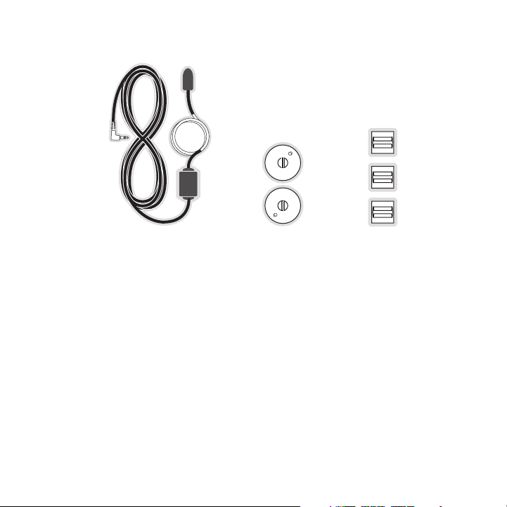
The following items are included with your purchase of the SIRIUS Stiletto 2 Vehicle Kit .
Unpack the kit carefully and make sur e that everything shown is present. If a nything is missing
or damaged, or if the kit fails to op erate properly, notify your dealer immed iately. It is recommended that you retain the original c arton and packing materials in case you need to shi p your
kit in the future.
Remot e Cont rolRemot e Cont rol
Anten na
Anten na
Cover /Tail
Cover /Tail
Mount ing
Mount ing
Screw s
Screw s
[ Pac ka ge Co nt ents ]
Vehic le Doc kVehic le Doc k Vehic le Mou ntsVehic le Mou nts
Magne tic
Magne tic
Anten na
Anten na
Cigar ette L ighte r
Cigar ette L ighte r
Adapt er
Adapt er
Alcoh ol Swa bAlcoh ol Swa b
7
Page 7
[ Pac ka ge Co nt ents ]
8
Sucti on Cup s (2)Sucti on Cup s (2)FM Ex tender Cabl eFM Ex tender Cabl e
Self Adhesi ve
Self Adhesi ve
Cable Guide s (3)
Cable Guide s (3)
Page 8
Controls
1 2 3 4 5
6
fm tune presetjump
7 8 9 0
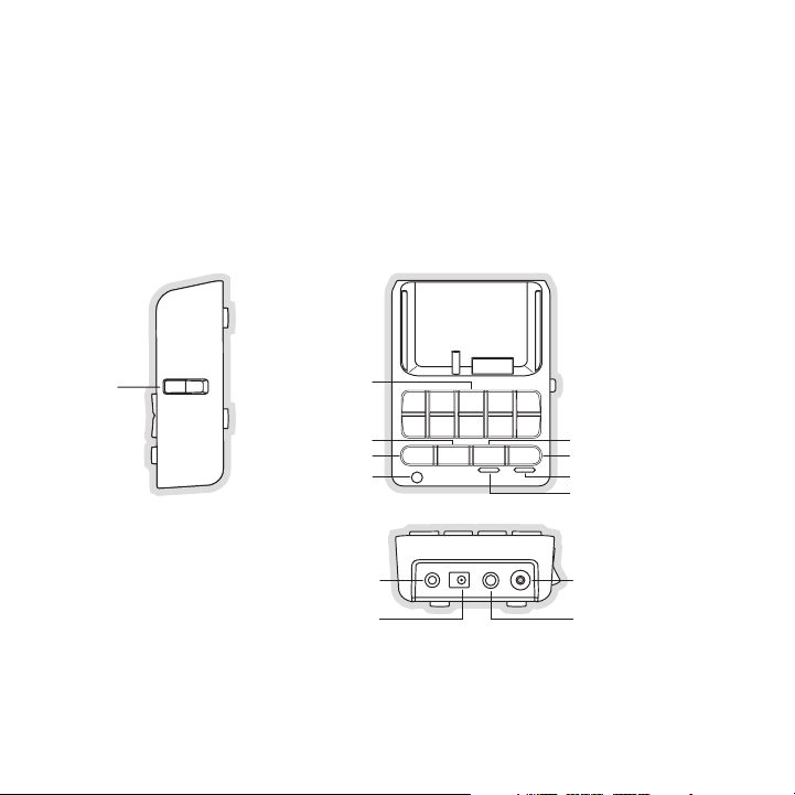
Direct Entry Tune/
Preset Buttons
POWER
ANT
Lock
Tune
Preset
Preset Mode Indicator
Tune Mode Indicator
FM
Jump
IR Remote Receiver
FM OUT
LINE OUT
lock
Figur e 1Figur e 1
Vehicle Dock
Figure 1 and the table following iden tify and describe the buttons, connector s, and feat ures of
the vehicle dock.
[ Con tr ols ]
9
Page 9

Butt on/
Conn ecto r
0 – 9
fm
jump
tune
pres et
lock
fm
powe r
line out
ant.
Vehi cle Dock But ton and Conn ecto r De scriptions
Acti on Desc ript ion
In T une Mode: Directly selects the ch annel indicted by the numbers which were pressed
Press
In P reset Mode: Selects presets 0 – 9
Displays the FM Frequency screen wher e the FM transmitter
Press
frequency can be selected, or an FM p reset selected using the
0 – 9 buttons
Jumps to a preselected traffic/weathe r channel
Press
A second press returns to the previou s channel or song/show
Changes to the direct tuning mode whe re channel numbers may
Press
be entered
Changes to the preset mode and displa ys the list of preset
channels
Press
The second and subsequent press cycle s through the preset
banks, A, B, and C
Toggle Se cures the S tiletto 2 in the vehicle dock
This connection is used for the FM Ex tender Cable (or optional FM Direct
Adapter which directly connects to th e vehicle’s FM radio antenna input)
Connection for the Cigarette Lighter Adapter
Audio output for direct connection to the vehicle’s audio system. An audio
cable (not supplied) is required to u tilize this connection
Connection for the Magnetic Antenna
10
[ Con tr ols ]
Page 10
Remote Control Reference Guide
1 2 3
+
4 5 6
7 8 9
jump
preset
options display
back home
mute
tune
FM
0
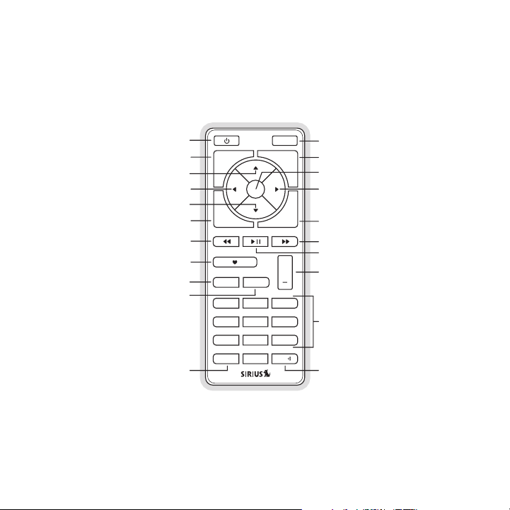
Select
FM
Jump
Preset
Tune
Media Dial (CCW)
Media Dial (CW)
Power
Love
Back
Options
Rewind
Rewind
Volume
Numeric
Keypad
Fast-Forward
Fast-Forward
Display
Home
Mute
Play/Pause
Figur e 2Figur e 2
Figure 2 and the table following iden tify and describe the buttons of the rem ote control . The
remote control works when the Stilett o 2 is in the vehicle dock.
[ Con tr ols ]
11
Page 11

Butt on Action
Remo te C ontr ol B utto n De scri ptio ns
Sate llit e Ra dio
Envi ronm ent
Inte rnet Rad io
Envi ronm ent
Repl ay/L ibra ry
Envi ronm ent
Up/D own
Left /Rig ht
opti ons
12
Powe r
Mute
Sele ct
back
home
[ Con tr ols ]
Press Turns the Stiletto 2 On/Off
Press Mutes (or un-mutes) the audio
Pressing Up is equivalent to turning the Media Dial counter-clockwise
Pressing Down is equivalent to turnin g the Media Dial clockwise
Press
If listening, displays channel or cat egory list
If in a list, menu, or prompt, scroll s to next or previous item
Pressing Right is equivalent to Fast- Forward
Press
Pressing Left is equivalent to Rewind
Press Selects highlighted item in a list, m enu, or prompt
Returns back to the screen displayed just prior to the currently
Press
displayed screen
First press returns to the Home scree n
Press
Additional press returns to the Now P laying screen
Displays available options for the cu rrently displayed screen
Press
If no options are available, nothing is displayed
Page 12

Butt on
disp lay
Play /Pau se
Rewi nd
Fast -For ward
Remo te C ontr ol B utto n De scri ptio ns C ontinued
Acti on
Press
Sate llit e Ra dio
Envi ronm ent
Cycles between the normal/near and ca r/far display mode, artist
name, and song title when in the chan nel browsing mode
Pauses a broadcast
Press
or resumes playing
a paused broadcast
Inte rnet Rad io
Envi ronm ent
If playing, mutes
audio
If muted, resumes
playing
If listening, rewinds
Press
Hold
a broadcast to the
previous song or
show
If in a channel or
preset list, moves
through categories
or preset banks
If listening, rewinds
through a broadcast
If listening and
muted, resumes
playing
If in a channel or
category list, moves
through channel
categories
If listening, fast-forwards in the replay
Press
Hold
buffer to the next
song or show
If in a channel or
preset list, moves
through categories
or preset banks
Fast-Forwards
through the replay
If listening and
muted, resumes
playing
If in a channel or
category list, moves
through channel
categories
buffer
Repl ay/L ibra ry
Envi ronm ent
Pauses or resumes
playing the current
song or show
Skips to the beginning of the song or
show
Rewinds through
song or show
Skips to the next
song or show
Fast-Forwards
through song or
show
[ Con tr ols ]
13
Page 13

Butt on
Love
+/–
Volu me
pres et
tune
0 - 9
Remo te C ontr ol B utto n De scri ptio ns C ontinued
Acti on
Press
Hold
Press
Press
Press
Press
Sate llit e Ra dio
Envi ronm ent
Saves the song or
show if possible, or
adds to the wish list
when song/show
cannot be saved
While recording,
prompts to stop
recording
Displays recording
setup screen
While recording,
prompts to stop
recording
+ increases the audio volume
— decreases the audio volume
Changes to the preset mode and displa ys the list of preset channels
A second and subsequent press cycles through the preset
banks, A, B, and C
Changes to the direct tuning mode whe re channel numbers may
be entered
In T une Mode: Directly selects the ch annel indicted by the numbers which are pressed
In P reset Mode: Selects presets 0–9
Inte rnet Rad io
Envi ronm ent
Adds the artist/song to the wish list
Repl ay/L ibra ry
Envi ronm ent
14
[ Con tr ols ]
Page 14
Remo te C ontr ol B utto n De scri ptio ns C ontinued
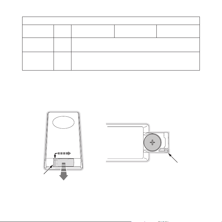
Latch Tab
Latch Tab
+
Figur e 3Figur e 3
Butt on
jump
FM
Rem ot e C on tRo l Batt eRy In stal lat Ion
To install the remote control battery , locate the battery drawer on the botto m edge. Ope n
the battery drawer by holding the lat ch tab to the right and sliding the draw er out as s hown
in Figure 3. Place the battery in dra wer with the + side of the battery facin g up and sl ide the
drawer back into the remote control.
Acti on
Press
Press
Sate llit e Ra dio
Envi ronm ent
Jumps to a preselected traffic/weathe r channel
A second press returns to the previou s channel or song/show
Displays the FM Frequency screen wher e the FM transmitter
frequency can be selected, or an FM p reset selected using the
0–9 buttons
Inte rnet Rad io
Envi ronm ent
Repl ay/L ibra ry
Envi ronm ent
[ Con tr ols ]
15
Page 15

Installation
SIRIUS suggests professional installa tion of this product in your vehicle. Pr ofessional installation provides an experienced techni cian to install this product in your veh icle, advic e for
selecting a suitable mounting locatio n, installation of the antenna, and rout ing all the necessary wires and cables. An installer w ill have the necessary audio connection accessories to
provide optimal audio output of the S IRIUS radio directly to your vehicle’s a udio system . Ask
your SIRIUS retailer if they provide professional installation services, or c an recommen d a
professional installation service.
Installing the Vehicle Kit
When installing the vehicle dock, cho ose a location in your vehicle where the radio will not
block your vision, interfere with the vehicle controls, or obstruct the air b ag. The loc ation
should be easily accessible and provi de good visibility of the display, and s hould not b e located where it will be in direct sunl ight which will affect the visibility of the displa y screen. The
right side of the vehicle dock which has the Lock button should also not be o bstructed.
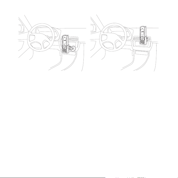
The mounting accessories necessary to install the vehicle dock in a vehicle a re provided .
Figure 4 shows two examples of the St iletto 2 mounted in a vehicle: A is the console mou nt
method using the adhesive mount, and B is the vent mount method.
16
[ Ins ta llati on ]
Page 16
A.
o
p
t
i
o
n
s
d
i
s
p
l
a
y
b
a
c
k
h
o
m
e
1
2
3 4
5
6
f
m
t
u
n
e
p
r
es
e
t
j
u
m
p
7
8
9
0
B.
o
p
t
i
o
n
s
d
i
s
p
l
a
y
b
a
c
k
h
o
m
e
1 2
3 4
5
6
f
m
t
u
n
e
p
r
e
s
e
t
j
u
m
p
7
8
9
0
Depending upon the mounting method yo u select, the mount should be assembled as
Figur e 4Figur e 4
described in one of the following two sections. In choosing a mounting locati on, be sure that
position chosen will not block access to the Lock button on the right side of the vehicl e dock.
Cons ole Moun t Me thod (A)
To assemble and mount the vehicle doc k for the console mount method A as shown in Figure
4:
Attach the adhesive foot to the vehic le dock using the provided screws. (Figu re 5)
1.
Before adhering the mount to the console, be sure to select your mounting position care-
2.
fully because once the mount has been adhered to a surface, it will not be po ssible to
remove it and adhere it again.
Clean the selected mounting surface a rea in the vehicle with the alcohol swab .
3.
Unscrew the adhesive foot from the mo unting bracket. Peel the protective mate rial off
4.
the adhesive on the foot and press th e foot firmly against the vehicle surfac e.
The adhesive mount should then be all owed to adhere for a minimum of 2-4 hour s before
5.
use. Best adhesion occurs after 24 ho urs. When the adhesive foot has achieved sufficient adhesion, reattach the vehicl e dock to the foot.
[ Ins ta llati on ]
17
Page 17

Mounting
Bracket
Vehicle
Dock
A
dhesive
Foot
Figur e 5Figur e 5
18
[ Ins ta llati on ]
Page 18
Vent Mou nt M etho d (B )
Figur e 6Figur e 6
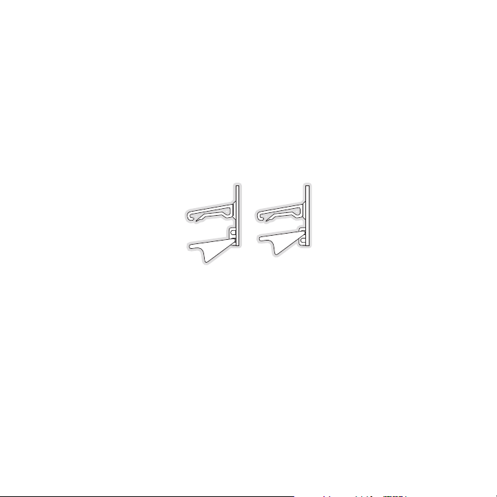
To assemble and mount the vehicle doc k for the vent mount method B as shown i n Figure 4:
Assemble the vent mount clip as shown in Figure 6. Note that the lower arm ma y be at-
1.
tached in two different positions. Yo u should assemble the vent clip in the c onfiguratio n
that works best in your particular ve hicle. Figure 6 illustrates both possibl e configura tions of the vent clip.
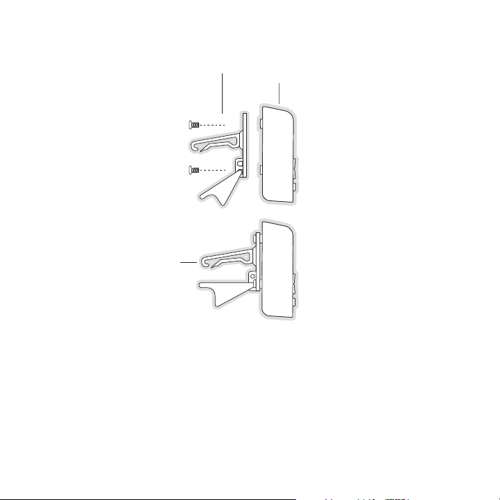
Attach the vent clip to the vehicle d ock using the provided screws. (Figure 7 )
2.
Slide the vent clip portion of the mo unt into a vent in your vehicle, insurin g that one of
3.
the vent louvers slides between the u pper and lower portions of the two clip arms, and
hooks the rear of the louver.
[ Ins ta llati on ]
19
Page 19
Vent Clip
Clip Arms
Vehicle
Dock
Figur e 7Figur e 7
20
[ Ins ta llati on ]
Page 20

Installing the Antenna
The installation of the magnetic ante nna consists of two installation steps:
Mounting the magnetic antenna and cov er/tail on the vehicle
•
Routing the antenna cable through the vehicle to the SIRIUS radio or vehicle dock
•
The following sections provide instru ctions for both installation steps.
ant en na mo unt In g
The SIRIUS Magnetic Mount Vehicle Ant enna has a strong magnetic mount designe d to hold
the antenna in place during normal dr iving conditions (highway/city). This al so allows f or easy
removal for transferring the antenna to other vehicles.
Figure 8 shows the optimal mounting l ocation for the antenna on several types of vehicle s.
These mounting positions should be ob served when installing the antenna:
Seda n/Coupe/SUV /Mini-Van: Install the antenna at the rear center of the roof, near the
•
rear window.
Pick up Truck: Install the antenna at the front center of the roof, near the w indshield.
•
Conv ertible: Install the antenna at t he front center of the trunk lid, near t he rear win dow.
•
The SIRIUS antenna needs to have an u nobstru cted area o f 3 inches by 3 in ches around
it. It is important to mount the ante nna where no obstructions will block the antenna fr om
receiving the SIRIUS signal. Objects which can obstruct the antenna could be a roof rack , a
sunroof, a roof mounted cargo contain er, another antenna, etc. If your vehicl e has a pot ential
obstruction, be sure that the SIRIUS antenna is mounted at least 3 inc hes away fr om it (but no
closer than 3 inches from the roof ed ge, or trunk lid in the case of a conver tible).
[ Ins ta llati on ]
21
Page 21

Figur e 8Figur e 8
Sedan /CoupeSe dan/C oupe
Picku p Truc kPic kup T ruck
SUV/M ini-Va nSUV/M ini-Va n
Conve rtibleConve rtible
Follow this procedure to mount the an tenna:
Select an appropriate mounting positi on for your type of vehicle that has an unobstruct-
1.
ed area of 3 inches by 3 inches aroun d the antenna.
Attach the rubber cover/tail to the a ntenna, as shown in Figure 9, and press the antenna
2.
cable into the rubber cover/tail. The rubber cover/tail will help to position the antenn a
the correct distance from the edge of the roof or trunk lid.
Clean the surface area of the vehicle where you will be installing the antenn a with the
3.
alcohol prep pad.
Peel the protective material from the adhesive strips (Figure 9) and press th e rubber
4.
cover/tail firmly into place on the v ehicle (Figure 10).
[ Ins ta llati on ]
22
Page 22

Rubber Cover/Tail
Protective Material
Adhesive Strips
Strain Relief
Antenna Cable
Figur e 9Figur e 9
Figur e 10Figur e 10
Double check that the location of the antenna and rubber cover/tail are corre ct, and
5.
continue to press firmly down on rubb er cover/tail for another 30 seconds. At room
temperature (68 degrees), maximum adh esion usually occurs within 72 hours. Du ring
this period, avoid car washes and oth er contact with the antenna and rubber a ntenna
cable cover/tail.
[ Ins ta llati on ]
23
Page 23

CaB le Ro ut Ing
1. Fe ed Cable Un der
Rubber Molding
A round Windo w
4. Rou te Cable fr om Trunk
Un der Interio r Trim, int o
Ca bin and Tow ards Front
of Vehicle
6. Br ing Cable O ut To
S IRIUS
Radio
Locati on
5. Bri ng Cable ou t from
Tr im and Rout e Under
Ca rpet to Das hboard
or Console.
2. Rou te Cable Ou t of
Wi ndow Moldin g and
In to Weathers tripping
Ar ound Trunk Opening
3. Rou te Cable Al ong
Tr unk Wall an d Into
Ca bin
Figur e 11Figur e 11
When you have successfully mounted th e antenna, you can begin the cable routi ng portion
of the installation. Separate antenna cable routing procedures are provided f or each typ e of
vehicle:
Seda n/Coupe on page 24
•
Pick up Truck on page 26
•
SUV/ Mini-Van on page 27
•
Conv ertible on page 28
•
Note that additional breakout illustr ations for each step of the antenna cabl e routing p rocedures can be found on the SIRIUS webs ite at http://www.sirius.com. Click on the Inst all/ Ac-
tiva te link and then follow the link for the Car Instal lation Tips .
Seda n/Co upe Ante nna Cabl e Ro utin g Pr ocedure
Figure 11 shows how the antenna cable should be routed from the antenna to yo ur SIRIUS
radio in a sedan/coupe.
24
[ Ins ta llati on ]
Page 24

Follow these detailed cable installat ion instructions:
Feed the cable from the antenna under neath the rubber molding around the rear window.
1.
Use a plastic putty knife or similar object to lift the rubber molding around the rear
window and tuck the antenna cable und erneath the molding. Route the antenna c able
around and down the window to the low est point. If your rear window does not have rubber molding, SIRIUS recommends consul ting with a professional installer.
Route the antenna cable out of the wi ndow molding and into the rubber weather strip-
2.
ping around the trunk opening. Lift t he weather stripping from the opening an d tuck the
cable inside it, then replace the wea ther stripping. To avoid sharp bends in the cable,
run the cable inside of the weather s tripping for a few inches, then remove t he cable
from the weather stripping inside of the trunk. Keep the cable away from hing es, gears,
etc., that could damage it.
Route the cable out from the rubber w eather stripping and along the trunk wal l. Continue
3.
routing the cable into the cabin thro ugh a conduit or along an existing wirin g harness.
Route the cable through the main cabi n area under the interior trim, towards the front
4.
of the vehicle. Use the plastic putty knife to lift the plastic trim just eno ugh to tuck the
cable under underneath. Avoid side ai rbag locations on back pillars and above the
doors. (Airbag locations are marked w ith “SRS” logos.) Be careful not to crim p or cut
the cable.
Bring the cable out from the trim nea r the firewall and route it under the ca rpet toward
5.
the dashboard or console. Coil any ex cess cable in a hidden location, such as under the
carpet, keeping it away from any vehi cle pedals or controls. Secure the exces s cable
with wire ties.
Bring the end of the cable out at the SIRIUS radio location. Leave yourself e nough cable
6.
so you can easily connect it to the a ntenna connector of the SIRIUS radio or vehicle
dock.
[ Ins ta llati on ]
25
Page 25

Pick up T ruck Ant enna Cab le R outi ng P rocedure
1. Rou te Cable
Un der Rubber
Mo lding Aroun d
Wi ndshield
2. Con tinue Tucki ng Cable
Un der Molding To
Bo ttom of Win dshield
3. Rou te Cable Ou t of Moldin g
an d Into Weat herstrippin g
Ar ound Door O pening.
Co ntinue to B ottom of
Do or Opening.
4. Bri ng Cable ou t from
We atherstripp ing and
Ro ute Under C arpet.
5. Bri ng Cable Ou t to
SI RIUS Radio
Lo cation
Figur e 12Figur e 12
Figure 12 shows how the antenna cable should be routed from the antenna to yo ur SIRIUS
radio in a pickup truck.
Follow these detailed cable installat ion instructions:
Use a plastic putty knife or similar tool to lift the rubber molding around t he windshie ld
1.
and tuck the antenna cable underneath it.
Continue tucking the cable underneath the windshield molding around the winds hield to
2.
the lowest corner.
At the lowest corner of the windshiel d, route the cable out of the windshield molding an d
3.
into the rubber weather stripping aro und the door opening. Lift the weather s tripping
from the opening and tuck the cable i nside it, then replace the weather strip ping. Run
the cable inside of the weather strip ping to the bottom of the door opening.
Pull the cable out of the weather str ipping at the bottom of the door opening and route it
4.
under the carpet toward the dashboard . Coil any excess cable in a hidden loca tion, such
[ Ins ta llati on ]
26
Page 26

1. Fe ed Cable U nder
Rubber Seal Arou nd
Hatch Opening
3. Ro ute Cable
Under Carpet
to Das hboard
4. Br ing Cable Out To
S IRIUS
Radio
Locati on
2. Rou te Cable U nder
In terior Tri m, int o
Ca bin and To wards
Fr ont of Veh icle
Figur e 13Figur e 13
as under the carpet, keeping it away from any vehicle pedals or controls. Sec ure the
excess cable with wire ties.
Bring the end of the cable out at the SIRIUS radio location. Leave yourself e nough cable
5.
so you can easily connect it to the a ntenna connector of the SIRIUS radio or vehicle
dock.
SUV/ Mini -Van Ant enna Cab le R outi ng P rocedure
Figure 13 shows how the antenna cable should be routed from the antenna to yo ur SIRIUS
radio in an SUV or a Mini-Van.
Follow these detailed cable installat ion instructions:
Feed the antenna cable underneath the rubber weather stripping of the rear ta ilgate
1.
window/door and route the cable along the rear hatch. Lift the weather stripp ing from
the opening and tuck the cable inside it, then replace the weather stripping. Pull the
cable out from weather stripping and route it into the cabin under the interi or trim. Av oid
hinges or gears that could crimp or c ut the cable.
Route the cable through the SUV’s mai n cabin area under the interior trim, to wards the
2.
[ Ins ta llati on ]
27
Page 27

6. Br ing Cable O ut To
D ocking Stat ion
Locati on and Conn ect
t o the Docki ng Station
1. Bri ng Cable fr om
An tenna Into Inside
of Trunk Lid
2. Tap e Cable Alo ng
In side of Lid to
Hi nge Strut
4. Rou te Cable fr om Trunk
Un der Interio r Trim, int o
Ca bin and Tow ards Front
of Vehicle
5. Bri ng Cable ou t from
Tr im and Rout e Under
Ca rpet to Das hboard
or Console.
3. Tie Cable to H inge Strut, Allowing
Sl ack for Lid to Open an d Close.
Ro ute Cable I nto Cabin
Th rough Exist ing Wire
Ch annel.
Figur e 14Figur e 14
front of the vehicle. Use a plastic p utty knife to lift the plastic trim just enough to tuck
the cable under underneath. Avoid sid e airbag locations on back pillars and a bove the
doors. (Airbag locations are marked w ith “SRS” logos.) Be careful not to crim p or cut
the cable.
Bring the cable out from the trim nea r the firewall and route it under the ca rpet toward
3.
the dashboard or console. Coil any ex cess cable in a hidden location, such as under the
carpet, keeping it away from any vehi cle pedals or controls. Secure the exces s cable
with wire ties.
Bring the end of the cable out at the SIRIUS radio location. Leave yourself e nough cable
4.
so you can easily connect it to the a ntenna connector of the SIRIUS radio or vehicle
cradle/dock.
Conv erti ble Ante nna Cabl e Ro utin g Pr ocedure
Figure 14 shows how the antenna cable should be routed from the antenna to yo ur SIRIUS
radio in a convertible.
[ Ins ta llati on ]
28
Page 28

Follow these detailed cable installat ion instructions:
Bring the cable from the antenna into the trunk at the front edge of the trun k lid. Keep
1.
any bends in the cable loose. Tape or tie the cable along the inside of the t runk lid to the
trunk lid hinge strut.
Allow enough slack in the cable so th e trunk lid can easily open and close an d keep the
2.
cable away from hinges, gears, etc., that could crimp or cut it. Route the ca ble along t he
trunk wall and into the cabin through a conduit or along an existing wiring h arness.
Route the cable through the main cabi n area under the interior trim, towards the front o f
3.
the vehicle. Use a plastic putty knif e to lift the plastic trim just enough t o tuck the cable
under underneath. Avoid side airbag l ocations on back pillars and above the d oors. (Airbag locations are marked with “SRS” l ogos.) Be careful not to crimp or cut th e cable.
Bring the cable out from the trim nea r the firewall and route it under the ca rpet toward
4.
the dashboard or console. Coil any ex cess cable in a hidden location, such as under the
carpet, keeping it away from any vehi cle pedals or controls. Secure the exces s cable
with wire ties.
Bring the end of the cable out at the SIRIUS radio location. Leave yourself e nough cable
5.
so you can easily connect it to the a ntenna connector of the SIRIUS radio or vehicle
dock.
[ Ins ta llati on ]
29
Page 29

Connecting the Cigarette Lighter Adapter
Power
Figur e 15Figur e 15
Connect the provided cigarette lighte r adapter to the P ower connection at the rear of th e
vehicle dock. (Figure 15)
Do not use any other power adapter fo r the vehicle dock, or connect it direct ly to the v ehicle’s
power. Doing so will damage the vehic le dock and the Stiletto 2. Using anything other th an
the supplied cigarette lighter adapte r to power the vehicle dock will void th e warranty.
30
[ Ins ta llati on ]
Page 30

Docking and Un-docking the Stiletto 2
1 2 3 4 5
6
fm tune presetjump
7 8 9 0
back
home
display
options
Satellite Radio
Internet Radio
Library
Figur e 16Figur e 16
When docking the Stiletto 2, be sure the Lock button of the vehicle dock is i n the unloc ked
position. (Refer to Figure 1 on page 9 for the location of the Lock button.) Grasp the v ehicle
dock with your free hand and place th e Stiletto 2 into the vehicle dock, as s hown in Fig ure
16, and slide it down until it is ful ly seated. Place the Lock button into th e locked po sition to
secure the Stiletto 2 in the vehicle dock.
To remove the Stiletto 2 from the veh icle dock place the Lock button in the u nlocked pos ition.
Grasp the vehicle dock with your free hand and pull the Stiletto 2 up until i t disengage s from
the vehicle dock.
[ Ins ta llati on ]
31
Page 31

Maximizing Audio Quality From Your Stiletto 2 Radio
1 2 3 4 5
6
fm tune presetjump
7 8 9 0
90.1
Vehicle Radio
SIRIUS Radio
FM Extender AntennaVehicle FM Antenna
Match Channels
There are two primary ways to connect your SIRIUS radio to your vehicle radio : Wirel ess
Conn ection or D irect C onne ction. The following sections will help you obtain the best pe rfor-
mance. For the latest information go to http ://www.siri us.com/vehi cleinst alla tion.
WIR el ess C onn eC tI on
Your SIRIUS radio contains an FM tran smitter. The FM transmitter sends the au dio from yo ur
SIRIUS radio to your vehicle radio. ( Figure 17)
Figur e 17Figur e 17
Included with your SIRIUS radio is an FM Extender Cable to maximize the audio quality of
your SIRIUS radio when using a wirele ss audio connection. Should the wireless audio qual ity
without the FM Extender Cable be not acceptable, you can try using the FM Ext ender Cable
(or opt for a direct connection).
Wire less Aud io C onne ctio n Wi thou t th e FM Extender Cable
To tune your vehicle’s FM radio and y our SIRIUS radio to the same FM channel (Figure 17) :
Turn off your Stiletto 2 and tune thr ough the FM channels on your vehicle’s F M radio 1.
[ Ins ta llati on ]
32
Page 32

90.1
FM Transmit
Turn the Media Dial to
change the frequency.
Use the number keys to
recall or assign FM
presets.
90.1 FM1
FM Transmit
Turn the Media Dial to
change the frequency.
Use the number keys to
recall or assign FM
presets.
Figur e 18Figur e 18
Figur e 19Figur e 19
to locate an FM channel that is not b roadcasting in your area. If you use an FM channel
that is being used by a local broadca ster, it will interfere with the perform ance of you r
SIRIUS radio. Once you have located a n FM channel that is not broadcasting in your
area, save it as a preset on your veh icle radio. This will become your SIRIUS preset.
Power the Stiletto 2 on. When it is completely powered up, press the fm FM button on
2.
the left side of the vehicle dock or press the FM bu tton on the remote control.
Use the Media Dial or the butt ons on the remote control to select the same FM
3.
channel. (Figure 18) Press and hold a preset number (0—9) on the vehicle dock in which
you want to store the selected FM cha nnel as a preset. (Figure 19) Press the S elect
button to exit and transmit on the se lected FM channel. The Stiletto 2 will t ransmit on the
selected FM channel.
Note : The FM transmitter in your SIRI US radio is automatically set to FM chan nel 88.1.
Note : The FM transmitter in your SIRI US radio is automatically set to FM chan nel 88.1.
This may not be the best channel in y our area.
This may not be the best channel in y our area.
Tip: If you regularly travel between cities with different active FM channels , you may
Tip: If you regularly travel between cities with different active FM channels , you may
need to find channels that are not br oadcasting in each city. The Stiletto 2 can store
need to find channels that are not br oadcasting in each city. The Stiletto 2 can store
multiple FM transmit channels as pres ets, so you can easily switch to the bes t FM
multiple FM transmit channels as pres ets, so you can easily switch to the bes t FM
channel for each city. You will also want to set the FM channels that are not broadcast-
channel for each city. You will also want to set the FM channels that are not broadcasting in each city as presets on your v ehicle radio.
ing in each city as presets on your v ehicle radio.
You should now hear the audio from yo ur SIRIUS radio over your vehicle’s FM r adio. If th e
audio quality is not satisfactory, yo u should install the FM Extender Cable a s described in the
following section (or use a direct co nnection as described on page 48).
[ Ins ta llati on ]
33
Page 33

Wire less Aud io C onne ctio n Us ing the FM Extender Cable
The FM Extender Antenna brings the FM signal transmitted from your SIRIUS rad io into clo se
proximity with your vehicle’s FM ante nna to provide a strong FM signal for go od receptio n.
(Figure 17) If you are using a FM wir eless connection to transmit the audio f rom your SI RIUS
radio to your vehicle’s FM radio, usi ng the FEA will provide an stronger FM s ignal with better
audio quality from your SIRIUS radio.
IMPO RTA NT N OTE: The FM Extender Anten na is placed insid e your vehicle in clos e
proximity to the vehicle’s FM antenna . In order for it to provide a strong FM signal for good
reception, it M UST be mounted in the correct location and orientation, as des cribed in t his
manual. The correct mounting location and orientation is determined by the ty pe and loca tion
of the vehicle’s FM antenna.
Step 1: Determine the type and location of your vehicle’s
FM antenna
Being able to determine the type and location of your vehicle’s FM antenna is the key to properly installing the FEA in your vehic le. The type and location of the FM ante nna in your vehicle
should be one of the following:
A. W hip/aerial mounted on the fro nt f ender o r hood: A fixed or retractable ae rial antenn a
located on the front fender or hood o f the vehicle.
B. W hip/aerial mounted in the A-p illa r of ca r frame: A fixed or retractable a erial anten na
located in the A-pillar of the vehicl e’s frame.
34
A.
[ Ins ta llati on ]
B.
Page 34

C. I n-glass, in the re ar w indshie ld: Several strands of wires in the rear windshield glass, usu-
ally near the top of the window. There is a difference between the rear window defroster wires
found in many vehicles and the FM antenna. The rear window defroster wires have uniform spacing and all wires run from edge to edge in the glass while the FM antenna wires have uneven
spacing, breaks in the wires, and some of the wires do not run from edge to edge in the glass.
D. Whip/aerial mounted on rear part of roof: A whip or aerial antenna mounted on the rear part of
the roof (often just above the back windshield glass). The whip or aerial should be 7 inches or longer.
E. W hip/aerial mounted on the rea r fe nder or trunk: A fixed or retractable wh ip or aeria l
antenna located on the rear fender or trunk of the vehicle.
F. Whip/aerial mounted on front part of roof: A whip or aerial antenna mounted on the front part of
the roof (often just above the front windshield glass). The whip or aerial should be 7 inches or longer.
G. I n-glass, in the front windshield: One or more strands of wire in the front windshield, usu-
ally near the top of the windshield.
H. I n-glass, in a rear sid e windo w: S everal strands of wires in a rear side w indow, espe cially
in some SUV, mini-vans and station wa gons.
C.
D.
F.
G.
E.
H.
[ Ins ta llati on ]
35
Page 35

Step 2: Prepare the FEA for temporary installation
ATTACH SUCTION CUPS AS SHOWN
ON BOTH ENDS OF THE THIN WIRE
THIS THINNER PORTION OF THE FEA IS
WHAT TRANSMITS THE FM SIGNAL TO
YOUR VEHICLE’S FM ANTENNA
DURING THE FINAL INSTALLATION USE THE CABLE
GUIDES TO HOLD THE CABLE IN POSITION UNTIL
IT REACHES THE INNER TRIM OR MOULDING
CONNECTS TO THE FM OUT
CONNECTOR OF YOUR
SIRIUS RADIO OR DOCK
ANTENNA CABLE
BEADARROW
Attach the suction cups to the antenn a portion of the FEA in the positions sh own in Figu re
20. The antenna portion of the FEA is the relatively thinner section of the c able in bet ween the
bead and the arrow, and transmits the FM signal to your vehicle’s FM antenna.
Figur e 20Figur e 20
Step 3: Temporarily install the FEA using the suction cups
for your vehicle’s antenna type
On the next several pages you will fi nd the FEA mounting location for your ty pe of FM an tenna
(A, B, C , etc.). Before attaching the FEA, clean the area where the suction cups will be mounted with the supplied alcohol swab. Th e antenna wire between the two suction c ups should be
pulled taut and as straight as possib le, and should not obstruct the driver’s view.
[ Ins ta llati on ]
36
Page 36

For vehicles wi th A an d B type FM antenn as:
Alternate Mounting
Location on Adjacent
A-Pillar
Whip/aerial mounted on the front fend er or hood
•
Whip/aerial mounted in the A-pillar o f car frame
•
Mount the FEA vertically on the front windshield at the edge of the glass, on the same side as
Figur e 21Figur e 21
the antenna (i.e. nearest to the antenna). (Figure 21) Clean the suction cup mounting areas with
the alcohol swab. The antenna wire between the two suction cups should be pulled taut, and as
straight as possible, and should not obstruct the driver’s view.
Caut ion: In some states it may not be legal to put the FEA on the windshield glass. In t his
case, the FEA should be mounted on th e A-Pillar adjacent to the vehicle’s FM antenna.
[ Ins ta llati on ]
37
Page 37

For vehicles wi th C an d D type FM antenn as:
FM ANTENNA
DEFROSTER WIRES
In-glass, in the rear windshield
•
Whip/aerial mounted on rear part of r oof
•
Mount the FEA horizontally along the top edge of the rear windshield. (Figure 4) For vehicles with
the roof top antenna, center the FEA below the antenna whip. For vehicles with the in-glass antenna,
the FEA should be directly over one of the FM antenna’s wires. Note: Do not install the FEA over
the defroster wires (see Figure 22). Be sure to locate it over one of the FM antenna wires. Clean
the suction cup mounting areas with the alcohol swab. The antenna wire between the two suction
cups should be pulled taut, and as straight as possible, and should not obstruct the driver’s view.
38
[ Ins ta llati on ]
Figur e 22Figur e 22
Page 38

For vehicles wi th an E type FM an tenna:
Whip/aerial mounted on the rear fende r or trunk
•
Mount the FEA vertically on the rear windshield at the edge of the glass, on the same side as
the antenna (i.e. nearest to the antenna). (Figure 23) Clean the suction cup mounting areas with
the alcohol swab. The antenna wire between the two suction cups should be pulled taut, and as
straight as possible, and should not obstruct the driver’s view.
Figur e 23Figur e 23
[ Ins ta llati on ]
39
Page 39

For vehicles wi th F or G type FM antenna s:
Alternate Mounting
Location Tucked
Behind Headliner
Whip/aerial mounted on the front part of roof
•
In-glass, in the front windshield
•
Mount the FEA horizontally along the top edge of the front windshield or install it into the
Figur e 24Figur e 24
headliner of the vehicle just above the front windshield. (Figure 24) For vehicles with the roof
top antenna, center the FEA below the antenna whip. For vehicles with the in-glass antenna, the
FEA should be directly over the antenna wire itself. Clean the suction cup mounting areas with
the alcohol swab. The antenna wire between the two suction cups should be pulled taut, and as
straight as possible, and should not obstruct the driver’s view.
Caut ion: In some states it may not be legal to put the FEA on the windshield so the FEA
should be installed into the headline r. Remove the suction cups and tuck the wire into t he
headliner, stretched taut and straigh t.
[ Ins ta llati on ]
40
Page 40

For vehicles wi th an H type FM an tenna:
In-glass, in a rear side window
•
If the in-glass antenna wires are vertical, mount the FEA vertically on the glass, directly over the
FM radio antenna. If the in-glass antenna wires are horizontal, mount the FEA horizontally on the
glass, directly over the FM radio antenna. (Figure 25) Clean the suction cup mounting areas with
the alcohol swab. The antenna wire between the two suction cups should be pulled taut, and as
straight as possible, and should not obstruct the driver’s view.
Figur e 25Figur e 25
[ Ins ta llati on ]
41
Page 41

Step 4: Connect the other end of the FEA into the FM
FM OUT
From FM Extender Antenna
OR
SILENC
E
ST
A
TIC
OUT connector of your SIRIUS vehicle dock
Plug the FM Extender Antenna into the FM OUT connector of the vehicle dock. ( Figure 26)
Figur e 26Figur e 26
Step 5: Find an FM channel which is not broadcasting in
your area
Turn off your SIRIUS radio. Turn on y our vehicle’s FM radio and tune through the FM chan nels
on your vehicle’s radio to locate an FM channel that is not broadcasting in y our area. ( Figure
27) You should only hear static or si lence on this channel. Use the tune func tion of you r radio
rather than the scan function to sear ch for a channel. If you’re not sure whi ch FM chann els are
not broadcasting in your home or trav el cities, you can also go to http://sirius.com/fmc hannel
and search for a suggested FM channel based on your zip code.
Figur e 27Figur e 27
If you use an FM channel that is being used by a local broadcaster, it will interfere with the performance of your SIRIUS radio. Once you have located an FM channel that is not broadcasting
42
[ Ins ta llati on ]
Page 42

in your area, save it as a preset on your vehicle radio. This will become your SIRIUS preset.
MATCH CHANNELS
1 2 3 4 5
6
fm tune presetjump
7 8 9 0
90.1
Step 6: Tune your SIRIUS radio to the same FM channel
Turn on your SIRIUS radio. For plug a nd play radios, press and hold the M enu button unti l
the FM Frequency screen is displayed. For Stiletto radios, select Setting s then Dock the n
FM T ransmit. For S50 radios, select S ettings then Devic e Settings then FM Fre quencie s.
Set the channel number on your SIRIUS radio to match the SIRIUS preset on you r vehicle’s
radio. (Figure 28) You should now hea r the audio from your SIRIUS radio over your vehicl e’s
FM radio. (Refer to the user guide wh ich accompanied your SIRIUS radio for mo re detailed
instructions on how to set the FM fre quency for your radio.)
Figur e 28Figur e 28
Note: The FM transmitter in your SIRI US radio is automatically set to FM chan nel 88.1. T his
may not be the best channel in your a rea. If you’re not sure which FM channe ls are not
broadcasting in your home or travel c ities, you can also go to http://sirius.com/fmchann el and
search for a suggested FM channel bas ed on your zip code.
Step 7: Optimize the placement of the FEA
Mute the volume of your SIRIUS radio. The easiest way to do this is to use th e MUTE 1.
[ Ins ta llati on ]
43
Page 43

button on the remote control. For mos t SIRIUS radios you can also press the M enu button and select Settings and then Audi o Level and turn the volume down to zero . (Refer
to the user guide which accompanied y our SIRIUS radio for more detailed instr uctions.)
Note, your SIRIUS radio is still on.
Turn up the volume of your vehicle’s FM radio. If you hear static or interfer ence adjust
2.
the position of the FEA until the sta tic or interference is eliminated or min imized. (Fi gure
291)
Figur e 29Figur e 29
3. If the level of static o r interfere nce is still high, please select another FM channel
3.
by repeating Step 6.
Step 8: Permanently install the FEA
If you are mounting the FEA in the headliner of the vehicle, skip this step. When you are satisfied with the mounting location, remove the suction cup mounts and peel the backing off the
bead and arrow adhesive mounts. Clean the area where the FEA will be attached with the alcohol
swab. Permanently adhere the FEA in the same position on the glass (or A-pillar), making certain
the wire is taut and is as straight as possible. Use the cable guides if necessary to hold the
cable (Figure 30)
44
[ Ins ta llati on ]
Page 44

REMOVE BOTH SUCTION CUPS
REMOVE
ADHESIVE BACKING
FROM BEAD
THIS THINNER PORTION OF THE FEA SHOULD BE
TAUT WHEN THE FEA IS PERMANENTLY ADHERED
USE THE CABLE GUIDES TO HOLD THE CABLE IN POSITION
UNTIL IT REACHES THE INNER TRIM OR MOULDING
REMOVE
ADHESIVE BACKING
FROM ARROW
Figur e 30Figur e 30
Step 9: Route and hide the cable through the vehicle to
your SIRIUS radio
Hide most of the cable by properly ro uting the antenna cable to your SIRIUS r adio. (Figu re
31) Use the cable guides to hold the cable in place until it reaches the inne r trim or m oulding
at the edge of the window. Take advan tage of any existing cable channel or wi ring condui t
and route the cable around the passen ger compartment to the vehicle dock. Tak e care not
pull the cable across sharp edges tha t could damage it, and keep it away from areas wher e it
might entangle feet. Coil and secure any excess antenna cable in a location w here it can be
hidden and secured (such as under the carpet or floor mat). Make sure the FEA is plugged
into the FM OUT connector of the radi o or vehicle dock.
This completes the FEA installation.
Figur e 31Figur e 31
[ Ins ta llati on ]
45
Page 45

Tips for Ide ntif ying the FM Ante nna
Correct identification of your vehicl e’s FM antenna is a key to a successful installatio n. The
preceding installation section alread y showed you the differing kinds of FM a ntennas fou nd
on vehicles, however, there are sever al types of antennas found on vehicles w hich you ma y
at first believe to be the FM antenna but in reality they are not. Instead th ey may actu ally be
GPS, OnStar®, cell phone, factory installed satel lite radio antennas, or other type of an tennas.
Please be aware of the following when identifying your vehicle’s FM antenna:
Puck type antennas and shark-fin type antennas are neve r the FM antenna. Figu re 32
1.
shows several types of these antennas which should not be mistaken for an FM antenna.
If you have located one of these type s of antennas on your vehicle you can be certain
that it’s not the FM antenna. Continu e your search to find the actual FM ante nna.
Figur e 32Figur e 32
46
[ Ins ta llati on ]
Page 46

Greater confusion may arise with whip type antennas. Figure 33 shows some whi p type
2.
antennas which can be found on a vehi cle’s front or rear roof, or on the rear windshield .
Some of these antennas could be the F M antenna and some are not the FM antenn a.
Antennas with a short 2-4 inch stubby whip or protrusion are no t FM antennas, while anten-
nas with a whip length of 7 inches or longer are likely to be the FM antenna. If your vehicle
has a short stubby antenna, you should continue searching your vehicle’s FM antenna.
If after searching your vehicle you’r e still uncertain as to where your FM an tenna is lo cated in
your vehicle then SIRIUS recommends p rofessional installation of the FM Exten der Antenna .
Ask your SIRIUS retailer if they prov ide professional installation services, or can reco mmend a
professional installer.
If the FM antenna is not correctly identified, the installation of the FEA will result in poor performance and unsatisfactory results.
Figur e 33Figur e 33
[ Ins ta llati on ]
47
Page 47

DIR eC t C on neC tI on s
1 2 3 4 5
6
fm tune presetjump
7 8 9 0
90.1
Figur e 34Figur e 34
A direct connection provides better a udio performance than a wireless connect ion and
removes the possibility of interferen ce from local FM broadcasters. There are several wa ys to
directly connect your Stiletto 2 whic h are explained in the following section s.
Tip: Depending on the model of radio in your vehicle and your level of comfor t with in-c ar
Tip: Depending on the model of radio in your vehicle and your level of comfor t with in-c ar
installations, a direct connection ma y require professional installation assi stance. Ask your
installations, a direct connection ma y require professional installation assi stance. Ask your
retailer or contact SIRIUS customer s upport for recommended installers in you r area.
retailer or contact SIRIUS customer s upport for recommended installers in you r area.
Dire ct W ired Aud io C onne ctio n
If your vehicle radio offers an “AUX IN” or “LINE IN” connection, it is the b est audio c onnection available. If the “AUX IN” or “L INE IN” connector is located on the fron t of your v ehicle
radio, this is also the easiest conne ction. (Figure 34)
Purchase an audio cable that matches the connection type of your vehicle radi o and your
1.
SIRIUS radio at your local electronic s retailer. Your SIRIUS radio requires a 1/8” stere o
male connector. Your local electronic s retailer can help you determine the pr oper connection for your vehicle radio.
Plug one end of the cable into the LI NE OUT jack on the vehicle dock. (Refer to Figure
2.
1 on page 9.) Plug the other end into your “AUX IN” or “LINE IN” jack on your vehicle
radio.
Note : Refer to your vehicle radio man ufacturer’s guidelines for correct insta llation.
Note : Refer to your vehicle radio man ufacturer’s guidelines for correct insta llation.
If the “AUX IN” or “LINE IN” connect ion is on the back of your vehicle radio , you may
If the “AUX IN” or “LINE IN” connect ion is on the back of your vehicle radio , you may
Note :
Note :
want to consider professional install ation. (Figure 35)
want to consider professional install ation. (Figure 35)
48
[ Ins ta llati on ]
Page 48

1 2 3 4 5
6
fm tune presetjump
7 8 9 0
90.1
Cass ette Ada pter
1 2 3 4 5
6
fm tune presetjump
7 8 9 0
90.1
Figur e 35Figur e 35
Figur e 36Figur e 36
If your vehicle radio has a cassette player:
Purchase a Cassette Adapter at your l ocal electronics retailer.
1.
Connect the adapter between the L INE OUT on the vehicle dock (refer to Figure 1 on
2.
page 9), and the vehicle radio’s cass ette slot. (Figure 36)
Note : Refer to the cassette adapter m anufacturer’s guidelines for correct use .Note : Refer to the cassette adapter m anufacturer’s guidelines for correct use .
[ Ins ta llati on ]
49
Page 49

SIRI US F M Di rect Ada pter
1 2 3 4 5
6
fm tune presetjump
7 8 9 0
90.1
FM
DIRECT
ADAPTER
Vehicle FM
Antenna
Figur e 37Figur e 37
If your vehicle radio does not have an “AUX IN” or “LINE IN” jack, the SIRIUS FM Direct Adaptor provides a wired connection between your Stiletto 2 and your vehicle radio, eliminating the
outside static and interference you sometimes experience when using a wireless FM connection.
(Figure 37) Professional installation may be required. See your local SIRIUS retailer. (The SIRIUS
FM Direct Adapter is available at your local SIRIUS retailer or at http://shop.sirius.com.)
50
[ Ins ta llati on ]
Page 50

Welcome to Sirius
The next few screens will
help you activate your new
satellite radio.
Next screen
Previous screen
Press the center SELECT
button to continue
Figur e 38Figur e 38
Subscribing to the SIRIUS Service
Before you can listen to the SIRIUS s ervice, you need to activate your subscr iption. The Stiletto 2 must be receiving the SIRIUS signal throughout the activation procedu re.
The Stiletto 2 has a built-in activat ion wizard which will guide you through the activat ion process. To subscribe your Stiletto 2, s imply follow the on-screen instructions. (Figure 38 )
[ Ins ta llati on ]
51
Page 51

Operation
preset
preset
10
Country Bord
James
Satellite
B
Presets
Presets (A, B, C)
Big ‘80s
Tracy Ullman
They Don’t Know (1983)
08 B1
The Pulse
Birdman & Lil Wayne
Stuntin’ Like My Daddy
09 B2
The Bridge
Rod Stewart
People Get Ready
10 B3
BBC Radio
Bob Sinclaire
Love Generation
11 B4
Figur e 40Figur e 40
Figur e 39Figur e 39
Battery Charging
To charge the battery in your Stilett o 2 place the radio in the vehicle dock. When docke d the
battery will be charged.
Presets
Channel presets may be selected using the vehicle dock to tune to a channel b y pushing t he
0—9 buttons when the vehicle dock is in the preset mode. The Stiletto 2 must be in the S atellite Radio mode to select presets. To select to a preset:
Press the
1.
indicate that the preset mode is acti ve.
Select the desired preset band (A, B, or C) by repeatedly pressing the
2.
ton until the desired preset band is displayed. (Figure 39)
Press one of the 0—9 buttons to selec t the desired preset
3.
OR
Use the Media Dial to highlight a preset and press the Selec t button. (Figure 40)
Preset button on the vehicle dock. T he preset mode indicator light will
Preset but-
52
[ Ope ra tion ]
Page 52

tune
10 32
Country Bord
James
Satellite Satellite
Direct
Tune
Enter
channel #
Li
ttle Richar
d
Lucill
e
32
Figur e 42Figur e 42
Figur e 41Figur e 41
Direct Channel Tuning
Channels may be tuned directly by ent ering the channel number using the 0—9 b uttons on t he
vehicle dock when the vehicle dock is in the tune mode, or by using the remot e. The Stil etto 2
must be in the Satellite Radio mode t o select channels. To directly tune a ch annel:
Press the
1.
light will indicate that the tune mod e is active.
Enter the channel number of the desir ed channel. If a 3-digit channel number is entered,
2.
the channel will be tuned immediately . If only one or two digits are entered, the channe l
will be tuned after a slight pause. ( Figure 42)
Tune button on the vehicle dock. (Fi gure 41) The tune mode indicator
[ Ope ra tion ]
53
Page 53

Jump Feature
jump
jump
jump
jump
jump
jump
jump
148
Satellite
NY Traffic
10
Country Bord
James
Satellite
Jump to
Traffic
Traffic & Weather Jump
Atlanta
Baltimore
Boston
Chicago
Dallas/Fort Worth
Detroit
Houston
Las Vegas
Figur e 43Figur e 43
Figur e 45Figur e 45
Figur e 44Figur e 44
The
Jump button on the vehicle dock allo ws you to jump to a pre-selected traffic /weather report for your location. The Stil etto 2 must be in the Satellite Radio mo de to use t he jump
feature.
When the
& 44) If the traffic/weather report f or your location is not immediately avai lable, a Wa iting for
loca l report message will be displaye d to indicate a jump is active. Once you r local rep ort is
ready, the Stiletto 2 will automatica lly tune to the traffic/weather report.
Pressing the
search. Pressing the
will return back to the channel to wh ich you had been tuned immediately prior to pressin g the
Jump button.
The traffic/weather report for your l ocation is associated with the
Sett ings menu. If you press the
location, you will be prompted to sel ect a location from a list of available cities. (Fi gure 45)
The Jump feature can be set by select ing from the Home screen, Set tings Dock Traffic/
Weat her Jump. (Figure 45 )
Jump button is pressed, the traffic/ weather report will be tuned. (Figures 4 3
Jump button while the traffic/weathe r report is pending will cancel the
Jump button after the radio has tune d to your traffic/weather report
Jump button using the
Jump button, but have not yet select ed a traffic/weather
54
[ Ope ra tion ]
Page 54

Auto Shutdown
Auto Shutdown
When in a car dock, your
device can automatically
shut down to limit the power
drawn from your car battery.
Shut down after 4 hrs
Never
Low Light Mode
If docked in your car, the
display can automatically
reduce its brightness when
the outside light is low.
On
Off
Figur e 47Figur e 47
Figur e 46Figur e 46
The auto shutdown feature will automa tically turn your Stiletto 2 radio off a fter 4 hour s if no
buttons have been pressed. This featu re will keep the battery in your vehicle from being discharged if the radio is inadvertently left on. The auto shutdown feature can be set by s electing
from the Home screen, Sett ings Dock Auto Shutdown. (Figure 46)
Low Light Mode
The low light mode feature will autom atically reduce the brightness of the di splay when the
ambient light is low, such as at nigh t. The low light mode feature can be set by selecti ng from
the Home screen, Settings Dock Low Light M ode. (Figure 47)
[ Ope ra tion ]
55
Page 55

Troubleshooting
Symp tom Solu tion
SIRIUS radio does not
power on
SIRIUS radio displays:
Ante nna Not Det ected
SIRIUS radio displays:
Acqu iring Signa l
Audio static or loss of
clarity
No sound The vehicle dock is not conn ected or is incorrectly connected
Blown fuse, or the vehicle dock does not have power or is not
properly connected.
Check the cigarette lighter adapter c onnection. Refer to the
vehicle’s owners manual for the locat ion of the vehicle’s fuse
panel and check for a blown fuse.
The satellite antenna is not connecte d to the vehicle dock.
Check the satellite antenna connectio n to the vehicle dock.
The Stiletto 2 is searching for a sat ellite signal.
Check for obstacles over or around th e satellite antenna.
Change the vehicle location to elimin ate nearby obstacles
(bridges, overpasses, tress, building s, etc).
The FM channel contains static.
Locate a unused FM channel on your ve hicle radio and set the FM
transmitter frequency of the SIRIUS r adio to match.
If using a direct connection, check t he cable connections.
Refer to the section, Maxi mizing Audi o Quali ty From You r
Stil etto 2 Radi o.
to the vehicle’s sound system. Refer to the section Max imizing
Audi o Quality F rom Your St iletto 2 Ra dio and follow the instructions carefully.
[ Tro ub lesho ot ing ]
56
Page 56

Optional Accessories
The following optional accessories ar e available for purchase from your SIRIU S retailer to
maximize your SIRIUS Stiletto 2 exper ience:
Home Kit (Mo del SLH2 )
The Stiletto 2 Home Kit is a compact home dock that provides everything
you need to use the Stiletto 2 in you r home or office. The sleek home dock
provides a convenient way to charge y our Stiletto 2’s battery along with an
extra slot for charging a spare batte ry. The included indoor/outdoor antenna
provides improved reception, while au dio cables enable you to connect the
Stiletto 2 to amplified speakers or a home entertainment system.
The kit includes a compact tabletop/d esktop home dock with FM output for wire less connectivity, a remote control, audio cables, an adjustable indoor/outdoo r windowsil l antenna w ith
20’ of cable, and an AC Adapter. Deta iled installation instructions are inclu ded with th e kit.
Exec utiv e So und Syst em ( Mode l SL EX2)
The Stiletto 2 Executive Sound System is a portable docking station and audio system for use with th e Stiletto 2 radio. With the
built-in amplifier and speakers, the system delivers rich, powerful
sound indoors or outdoors, and featur es an auxiliary input for
other audio devices. Included with th e system is an adjustable
indoor/outdoor windowsill antenna wit h 20’ of cable and an AC
adapter.
FM D irec t Ad apte r (P rodu ct N o. 1 4100 )
The FM Direct Adapter directly connec ts the FM signal from your SIRIUS radio to your
vehicle’s AM/FM radio, reducing any i nterference which might be present from FM radio st ation broadcasts. When the SIRIUS radi o is turned off, the vehicle’s FM antenn a is automa tically connected back to the vehicle’s AM/FM radio. The adapter connects direc tly in-line with
the vehicle’s existing AM/FM antenna input. SIRIUS recommends professional in stallation of
this product.
[ Opt io nal A cc essor ie s ]
57
Page 57

Warranty
12 M onth War rant y
SIRIUS Satellite Rad io I nc. (the “Co mpany”) warrants to the original retail pur chas er o f th is p roduct
that should this pro duct or any part thereof, under normal use and conditio ns, be p rove n de fect ive in
material or work mans hip with in 1 2 mo nths from the date of original purchase , su ch d efec t(s) wil l be
repaired or repl aced wit h ne w or rec onditioned product (at the Company’s op tion ) wi thou t ch arge for
parts and repair lab or. To o btai n re pair or replacement within the terms of thi s Wa rran ty, the product
is to be deliver ed w ith proo f of war ranty coverage (e.g. dated bill of sale ), s peci fica tion of defect(s),
transportation p repa id, to t he l ocat ion shown below under WARRANTY RETURN.
This Warranty do es n ot e xten d to the elimination of externally generated st atic or nois e, t o co rrection
of antenna probl ems, to cost s in curr ed for installation, removal or reinsta llat ion of t he p rodu ct, or to
damage to tapes, com pact dis cs, spea kers, accessories, or vehicle electrica l sy stem s.
This Warranty do es n ot a pply to any product or part thereof which, in the o pini on o f th e Co mpan y,
has suffered or been dam aged thr ough alteration, improper installation, mis hand ling , mi suse , ne glect,
accident, or by remo val or d efac emen t of the factory serial number/bar code lab el(s ). T HE E XTEN T
OF THE COMPANY’S LIA BILI TY U NDER THI S WARRANTY IS LIMITED TO THE REPAIR OR
REPLACEMENT PROV IDED ABO VE A ND, IN N O EVENT, SHALL THE COMPANY’S LIABILITY
EXCEED THE PURCH ASE PRIC E PA ID B Y PU RCHASER FOR THE PRODUCT.
This Warranty is in lieu of all othe r express warranties or liabilities. AN Y IM PLIE D WA RRAN TIES , INCLUDING ANY IMPL IED WARR ANTY OF MERC HANTABILITY, SHALL BE LIMITED TO THE DU RATION OF THIS WRI TTEN WAR RANT Y. A NY A CTION FOR BREACH OF ANY WARRANTY HEREUNDER INCLUDING ANY IMPL IED WARR ANTY OF MERCHANTABILITY MUST BE BROUGHT
WITHIN A PERIOD OF 4 8 MO NTHS FRO M DA TE OF ORIGINAL PURCHASE. IN NO CASE SHA LL
THE COMPANY BE L IABL E FO R AN Y CO NSEQ UENTIAL OR INCIDENTAL DAMAGES FOR
BREACH OF THIS O R AN Y OT HER WARR ANTY , EXPRESS OR IMPLIED, WHATSOEVER. No
person or repres enta tive is auth oriz ed to assume for the Company any liabil ity othe r th an e xpre ssed
herein in connec tion wit h th e sa le o f this product. Some states do not allo w li mita tion s on how long
an implied warra nty last s or the exc lusion or limitation of incidental or c onse quen tial dam age so the
above limitation s or exc lusi ons may not apply to you. This Warranty gives y ou s peci fic lega l ri ghts and
you may also hav e ot her righ ts w hich vary from state to state.
WARRANTY RETURN: To obta in r epai r or replacement within the terms of this W arra nty, ple ase return product to an a utho rize d re tail er or call Customer Service at 1-800-86 9-51 87; proo f of pur chase
and description of d efec t ar e re quir ed. Products to be returned to an appro ved warr anty sta tion must
be shipped freig ht p repa id.
58
[ War ra nty ]
Page 58

Specifications
Cigarette Lighter Adapter Fuse Requir ement . . . . . . . . . . . . . . . . . . . . . . . . . . . . 2 A Slow Blow
Cigarette Lighter Adapter Cable Lengt h . . . . . . . . . . . . . . . . . . . . . . . . . . . . . . . . . . . 1.8m (6ft.)
Cigarette Lighter Adapter Operating T emperature . . . . . . . . . . -20° to +85° C (-4° to +185° F)
Vehicle Dock Power Requirements . . . . . . . . . . . . . . . . . . . . 10-16 Volts , Negative Ground, DC
Antenna Type . . . . . . . . . . . . . . . . . . . . . . . . . . . . . . . . . . . . . . . . . . . . . . . .L ow Profile Magnetic
Antenna Cable Length . . . . . . . . . . . . . . . . . . . . . . . . . . . . . . . . . . . . . . 21’ (single micro-cable)
Connector Type . . . . . . . . . . . . . . . . . . . . . . . . . . . . . . . . . . . . . . . . . . . . . . . . SMB (right-angle)
Audio Interface . . . . . . . . . . . . . . . . . . . . . . . . . . . . . . . . . . . . . . . . . . . 1/8” / 3.5mm Stere o Jack
[ Spe ci ficat io ns ]
59
Page 59

Copyrights & Trademarks
© 2007 Sirius Satellite Radio Inc. Al l Rights Reserved.
® “SIRIUS”, the SIRIUS dog logo, chan nel names and logos are trademarks of Si rius Satell ite
Radio Inc. All Rights Reserved. OnSta r is a registered trademark of OnStar Co rporation.
“Stiletto 2” is a trademark of Siriu s Satellite Radio Inc.
™
Hardware, subscription, and activatio n fee required. For full Terms & Conditi ons, visit
http://sirius.com. Prices and program ming are subject to change. Not availabl e in HI and AK.
Equipment and subscription sold separ ately. Installation required with some e quipment.
[ Cop yr ights & Trad em ark s ]
60
Page 60

SIRIUS ID
Write down the SIRIUS ID (SID) of you r Stiletto 2 in the space provided below .
SID: _______________________________________
[ SIR IU S ID ]
61
Page 61

Page 62

SIRI US Customer Servic e: 1-888-539-74 74
customercare@sirius-radio.com
SIRI US Satellit e Radio Inc .
1221 Avenue of the Americas
New York, NY 10020
1-888-539-7474
http://www.sirius.com
Page 63

 Loading...