

Page 1
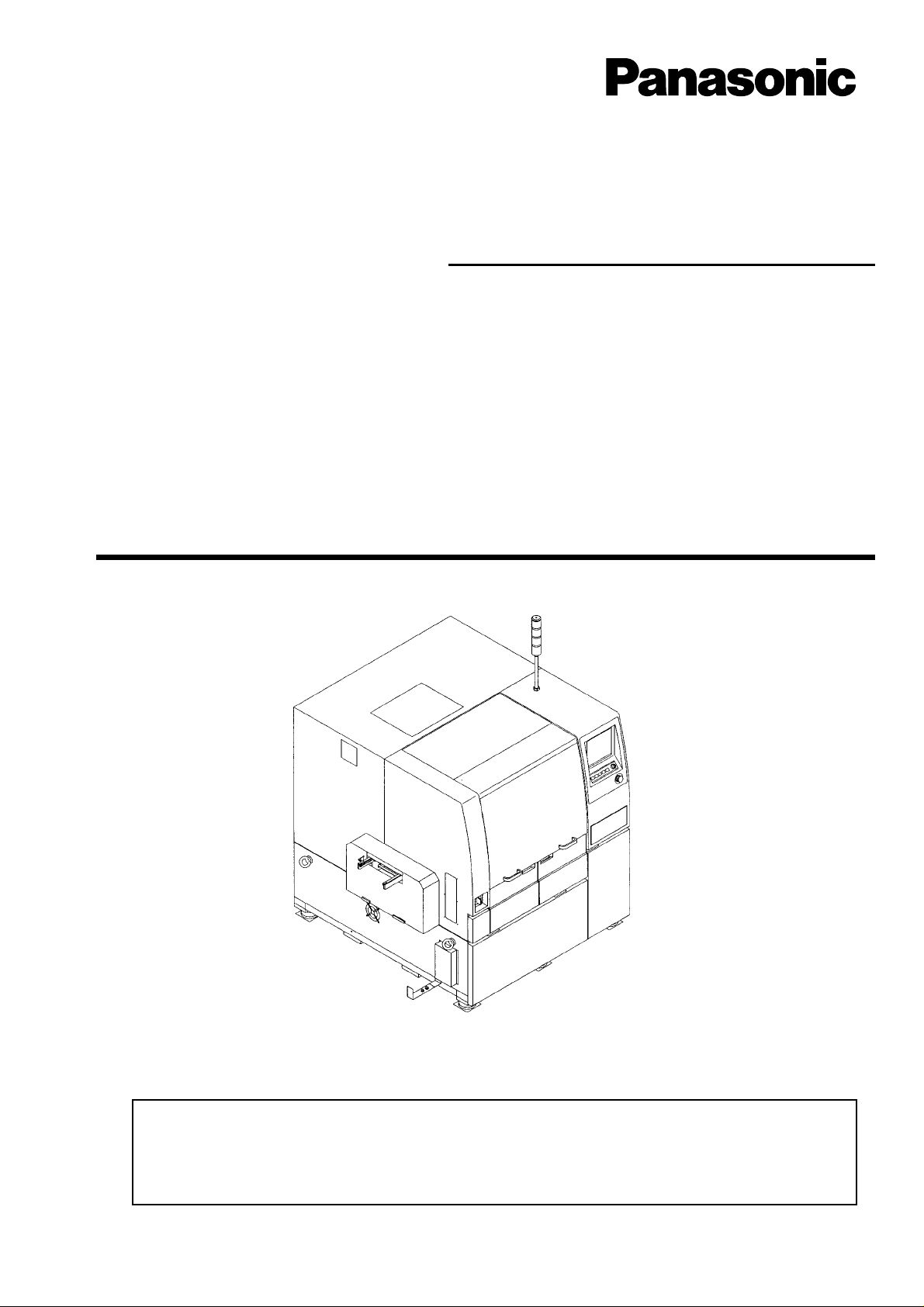
Screen Printer SP22P
Operating Instructions
Model No.
KXF-193C
Operating Manual(Operators)
Thank you for purchasing SP22P, the screen printer.
Before placing the machine in service, be sure to read the instruction manual for
proper usage.
After that, store it carefully and it if necessary.
193C-E-OMAB-0002
Page 2

Page 3

WARNING
DO NOT ALLOW ANY PERSON WHO HAS NOT RECEIVED SPECIAL TRAINING
TO OPERATE THE MACHINE.
The machine may be operated improperly and injure you.
Either carry out training by yourself, or consult the manufacturer.
M11E
193C-E-OMA00-B01-00
Page 3
Page 4
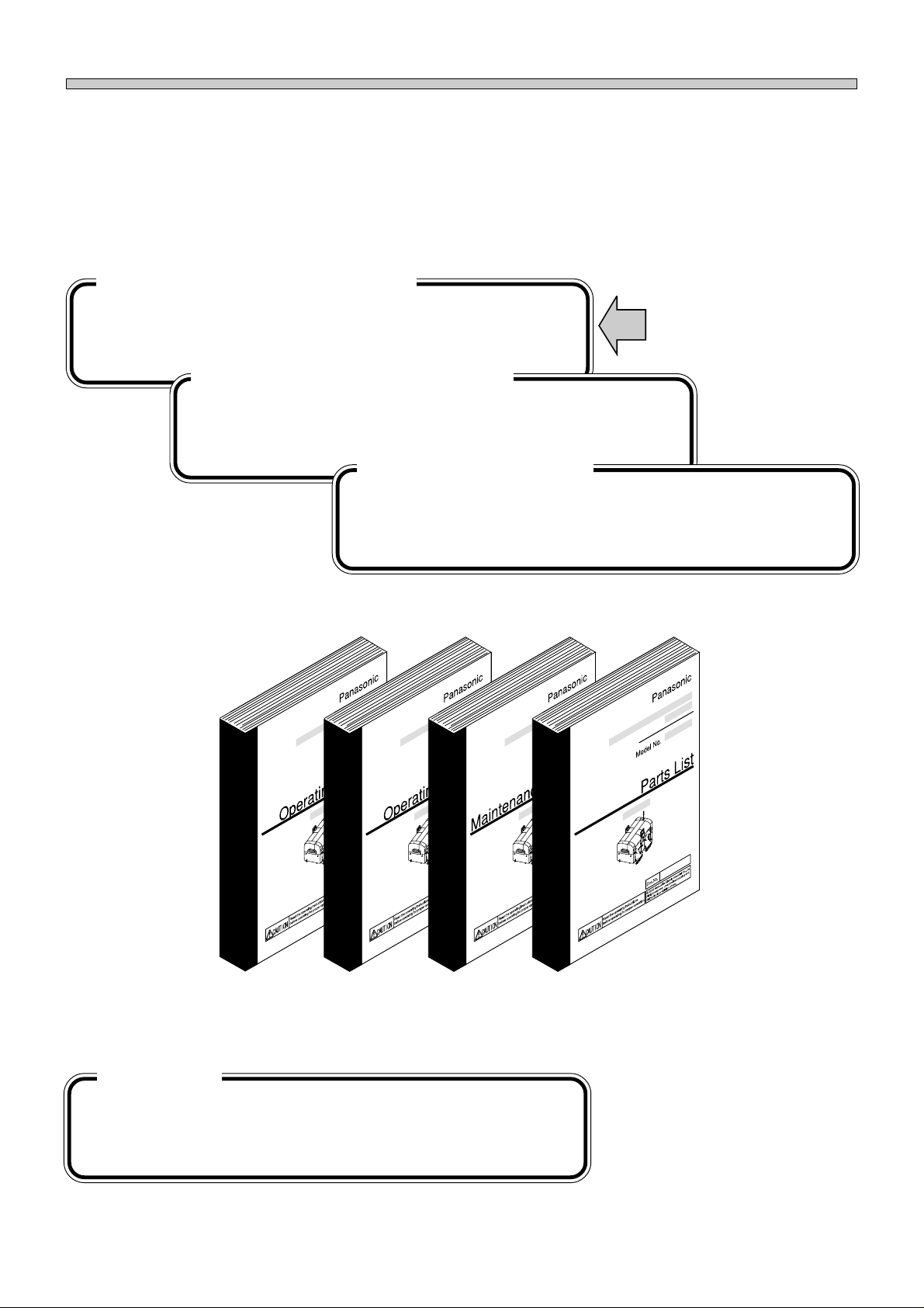
ORGANIZATION OF MANUALS
4 manuals are attached to this machine. They are classified into 4 types. Use each manual according
to the working purpose and person in charge.
The production data of the line including this machine are programmed on PT. Refer to the instruction
manuals accompanied with PT.
Operating manual (operators)
This manual is for the machine operators, and describes the operating
procedure, precautions and information which is necessary for safe
and effective operation.
Operating manual (engineers)
This manual is for the machine engineers, and describes operation
method and teaching of boards and parts.
Maintenance manual
This manual is for machine maintenance, and describes the daily
checks, adjustment and replacement of consumable parts.
Troubleshooting is also included.
This manual
Manuals of this equipment
Parts List
The assembly of each unit is individually indicated by an exploded
view of the parts. Use this for ordering parts or confirming the assembly of the units.
Page 4
193C-E-OMA00-B01-00
Page 5

Operating Manual
Operating Manual
For Operators
SAFETY PRECAUTIONS
GENERAL DESCRIPTION
BASIC OPERATION
DAILY PRODUCTION
PRODUCTION SETTINGS
PRODUCTION INFORMATION
SETTING PRODUCTION MATERIALS
TROUBLESHOOTING
APPENDIX
1
2
3
4
5
6
7
193C-E-OMA00-A02-15
Page 5
Page 6

SAFETY PRECAUTIONS.................................................................. 9
Chapter
Chapter
1
1-1 Names and Mechanism of Each Unit ......................................................... 1-2
1-2 Printing Mechanism....................................................................................1-8
1-3 Production Work Flow .............................................................................. 1-10
2
2-1 Operating Panel ......................................................................................... 2-2
2-2 Touch Panel................................................................................................ 2-3
2-3 Help Function ............................................................................................. 2-7
2-4 Main Menu.................................................................................................. 2-8
GENERAL DESCRIPTION
BASIC OPERATION
2-2-1 Touch Panel Configuration ..................................................................................2-3
2-2-2 Switch Types and Operation Method ..................................................................2-4
2-2-3 Function Keys .....................................................................................................2-5
2-2-4 Messages............................................................................................................2-6
2-4-1 Contents of Main Menu.......................................................................................2-8
Chapter
3
3-1 Before Production....................................................................................... 3-2
3-2 Starting Production..................................................................................... 3-5
3-3 During Production....................................................................................... 3-8
3-4 Production Stop.......................................................................................... 3-9
3-5 Completion of Production ......................................................................... 3-12
DAILY PRODUCTION
3-1-1 Start-up Inspection..............................................................................................3-2
3-1-2 Checking Air Pressure ........................................................................................3-3
3-1-3 Starting up Machine ............................................................................................3-4
3-2-1 Starting Operation ...............................................................................................3-5
3-2-2 Self Diagnosis .....................................................................................................3-6
3-2-3 Return to Origin...................................................................................................3-7
3-3-1 Information and Functions during Production .....................................................3-8
3-4-1 Stop Operation....................................................................................................3-9
3-4-2 Information and Functions during Stop ............................................................. 3-11
3-4-3 Restarting Production........................................................................................3-11
3-5-1 Automatic Stop..................................................................................................3-12
3-5-2 Finishing Machine .............................................................................................3-12
Page 6
193C-E-OMA00-A02-00
Page 7

Chapter
4
4-1 Squeegee Open/Close ............................................................................... 4-2
4-2 Board Transport.......................................................................................... 4-3
4-3 Mask Cleaning............................................................................................ 4-4
4-4 Counter Reset ............................................................................................ 4-5
PRODUCTION SETTINGS
Chapter
Chapter
Chapter
5
5-1 Run Information.......................................................................................... 5-2
5-2 Stop Information ......................................................................................... 5-3
5-3 Counter Information.................................................................................... 5-6
5-4 Form Printing.............................................................................................. 5-7
5-5 Reset .......................................................................................................... 5-8
6
6-1 Setting Mask............................................................................................... 6-2
6-2 Supplying Solder ........................................................................................ 6-4
6-3 Supplying Cleaning Paper........................................................................ 6-12
6-4 Supplying Cleaning Solvent ..................................................................... 6-16
7
PRODUCTION INFORMATION
SETTING PRODUCTION MATERIALS
6-2-1 Case that “AutoSolderSupply” Is OFF.................................................................6-4
6-2-2 Case that “AutoSolderSupply” Is ON ..................................................................6-8
TROUBLESHOOTING
7-1 Error Messages (Error List) ........................................................................ 7-2
7-2 Check and Solutions .................................................................................. 7-6
193C-E-OMA00-A02-02
7-1-1 Errors during the Self-diagnosis..........................................................................7-2
7-1-2 Immediate Stop Error..........................................................................................7-3
7-1-3 Emergency Stop Error ........................................................................................7-4
7-2-1 Emergency Switch On ........................................................................................7-6
7-2-2 Servo Switch .......................................................................................................7-6
7-2-3 Air Pressure Drops..............................................................................................7-7
7-2-4 Pre Process Production End...............................................................................7-7
7-2-5 Cover Open.........................................................................................................7-8
7-2-6 Thermal Trip Detection........................................................................................7-8
7-2-7 Power Box Fan Motor .........................................................................................7-9
7-2-8 Temperature Sensor............................................................................................7-9
7-2-9 Lift Axis Brake off
Under Axis Brake off .........................................................................................7-10
7-2-10 PCB Recognition Error...................................................................................... 7-11
Page 7
Page 8

7-3 The Input and Output Check of Machine.................................................. 7-12
7-3-1 Input Check after Error......................................................................................7-12
7-3-2 Output Check after Error...................................................................................7-13
INDEX
Appendix
Appendix
A
B
MASK FRAME REARRANGING
PROCEDURE
BOARD VACUUM BOX
Page 8
193C-E-OMA00-A02-02
Page 9
SAFETY PRECAUTIONS
The precautions that must be observed in order to prevent injury to the user or another
person, or damage to property, are as follows.
The degree of danger or injury resulting from incorrect use due to failure to read an indication is classified and described as follows.
This indication refers to a situation which is considered that
DANGER
there is imminent danger of death or serious injury.
Be sure to observe
WARNING
CAUTION
The matters should be observed are classified and described according to the symbols
shown below.
(The followings are only some examples of the symbolic indications.)
These symbols indicate matters to which attention must be paid.
This symbol indicates an action that must not be carried out.
This symbol indicates an action that must be carried out.
This indication refers to a situation which is considered that
there is a possibility of death or serious injury.
This indication refers to a situation which is considered that
there is a possibility of only injury or physical damage.
193C-E-OMA00-A03-01
Page 9
Page 10
SAFETY PRECAUTIONS
Be sure to observe
WARNING
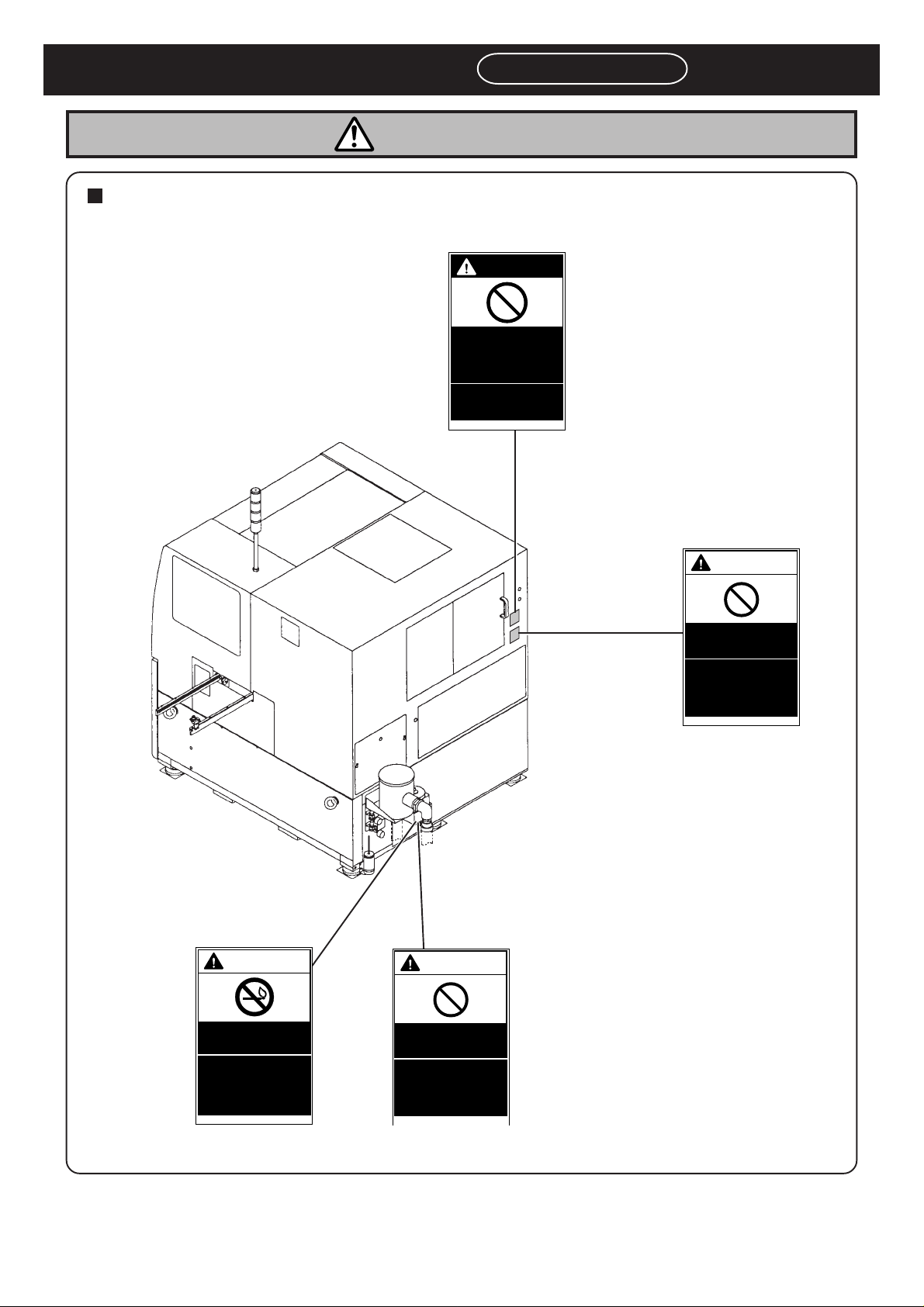
Follow the warning indication.
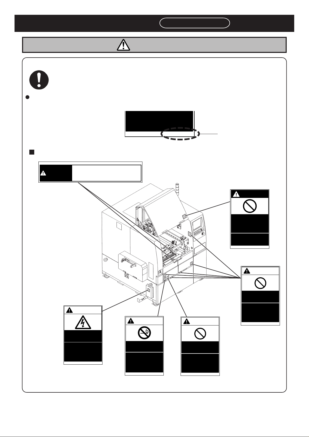
This is a label for ensuring the safe machine use. If you do not observe it, there is a risk of human
injury or damage to property.
The following warning labels are pasted on this machine. Follow the instructions on each label. If a label has
come off, put a new one on a proper position. To order a label from the manufacturer, refer to PARTS LIST.
feeder tables will have
serious injury.
0 1 J Q B
Front view of warning label indicated positions
0 8 6 R A
DANGER
DON'T TOUCH THIS PART
WHEN OPERATING
Label part No.
DANGER
DO NOT OPEN
THE COVER
WHEN
OPERATING
You will have serious
injury if you touch the
active part inside.
0 1 K 1 B
WARNING
M32E
Page 10
193C-AC02
WARNING
ELECTRIC
SHOCK
You will have serious
electric shock if you
touch electric active
part inside.
0 1 N C B
WARNING
NO OPEN
FLAME
Solvent may catch
fire.
Keep away from fire.
0 8 F 1 A
Attached to the front and
reverse side of cover.
CAUTION
IPA
USE ONLY
The corrosion damage
to the hose may cause
the machine to catch
fire.
0 7 R 3 A
Attached to the front and
reverse side of cover.
DO NOT DISABLE
SAFETY SENSOR
You will have serious
injury by active part
if you disable safety
sensor.
0 1 P 9 B
193C-E-OMA00-A03-00
Page 11
SAFETY PRECAUTIONS
WARNING
Rear view of warning label attached positions
DANGER
DO NOT OPEN
THE COVER
WHEN
OPERATING
You will have serious
injury if you touch the
active part inside.
Be sure to observe
0 1 K 1 B
193C-AB00
WARNING
CAUTION
WARNING
DO NOT DISABLE
SAFETY SENSOR
You will have serious
injury by active part
if you disable safety
sensor.
0 1 P 9 B
M32E
193C-E-OMA00-A03-00
NO OPEN
FLAME
Solvent may catch
fire.
Keep away from fire.
0 8 F 1 A
IPA
USE ONLY
The corrosion damage
to the hose may cause
the machine to catch
fire.
0 7 R 3 A
Page 11
Page 12
SAFETY PRECAUTIONS
Be sure to observe
WARNING
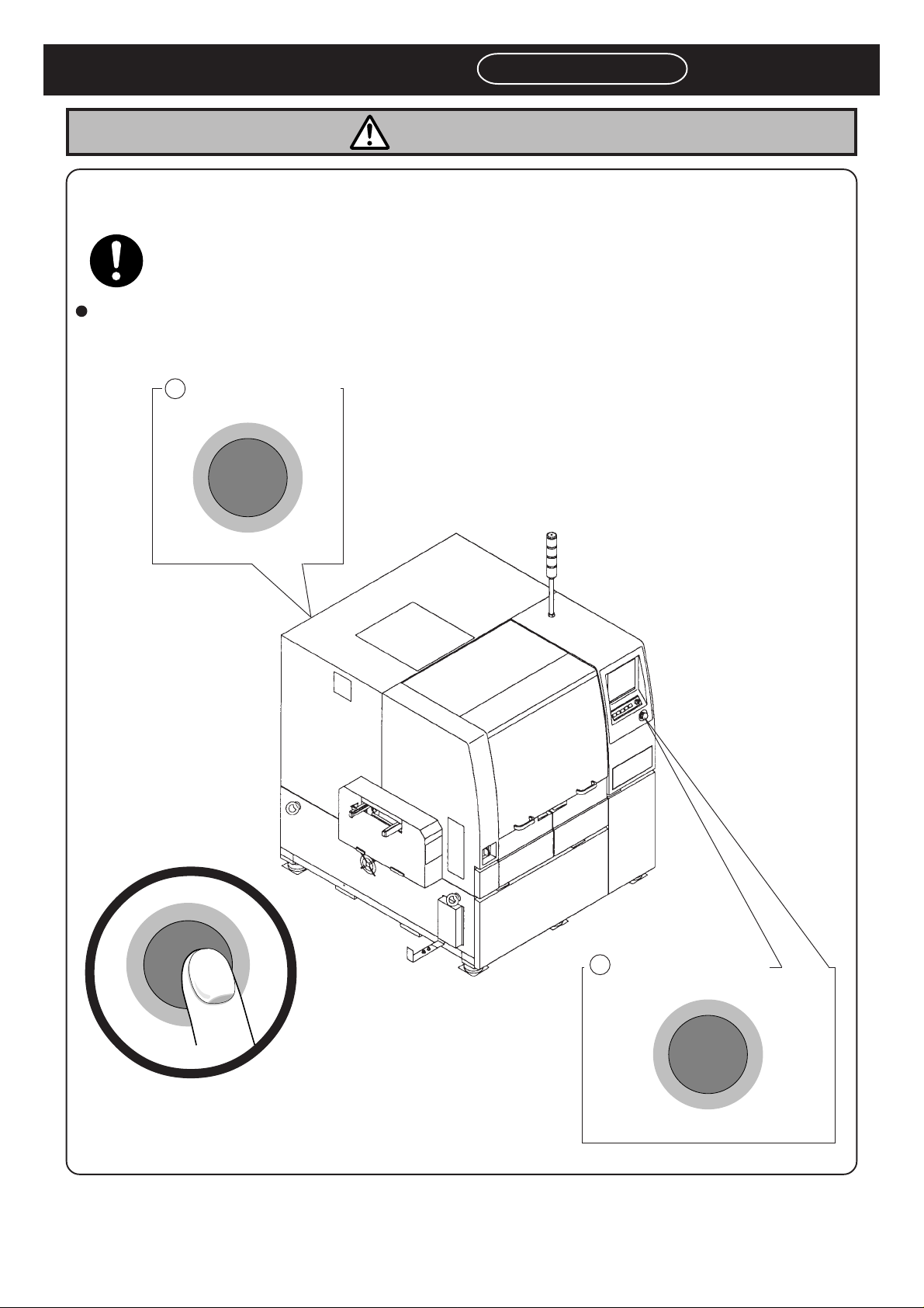
If you sense any danger or abnormality, press an emergency stop button to
stop the machine.
If you continue to operate the machine in a dangerous or abnormal state, a breakdown or an
accident will occur.
There are two emergency stop buttons. Pressing any one of them stops operation. Press the nearest
Remove the cause of the danger or abnormality, then re-start the machine. To reset the emergency
pull it forward.
2 Left pole on rear side
G
E
R
N
E
M
E
C
Y
S
P
T
O
stop button,
one.
M33E-2B
Page 12
G
E
R
N
E
M
E
S
C
Y
1 Front operation panel
P
T
O
193C-AA00
G
E
R
N
E
M
E
C
Y
S
P
T
O
193C-E-OMA00-A03-00
Page 13
SAFETY PRECAUTIONS
SELECT
OFF ( )
ON ( )
SERVO
Be sure to observe
WARNING
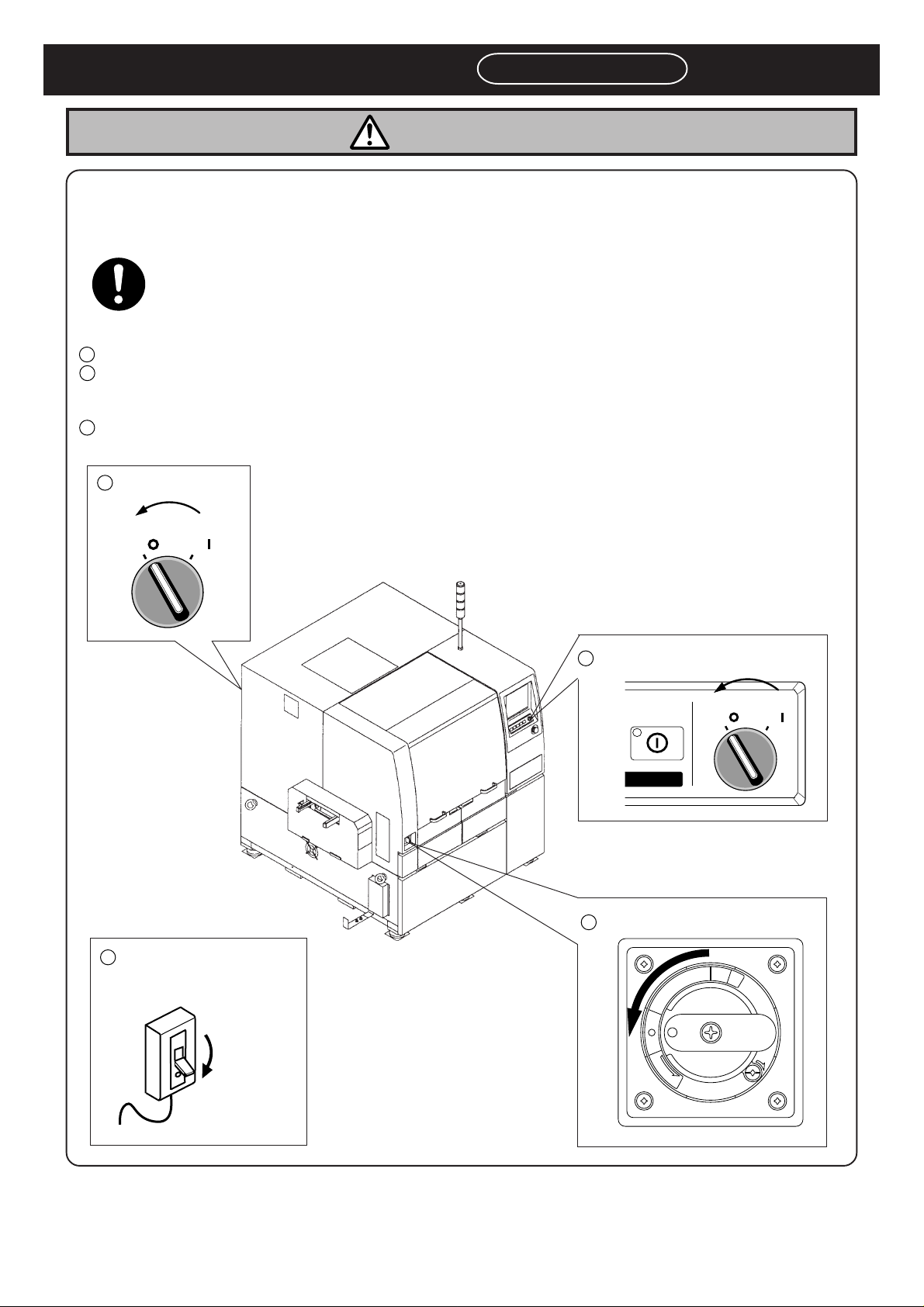
Observe the following items before placing your hand or other part of your
body in an active part of the machine in order to feed production material,
change machine set-up, or adjust machine settings.
You may be injured if the machine is actuated. Also you may be struck by an electric shock.
There are three levels of procedure, shown below, for each kind of work.
Cutting off the power supply of the machine ----------- For repairing the control box.
1
Power supply OFF-------------------------------------------- This is used to turn off power supply normally.
2
For replacing the control part such as the sensor
For disassembling or replacing parts
3
Servo switch OFF--------------------------------------------- For changing production board and daily inspection
For placing or removing board on the conveyor
For setting production materials such as the feeder
3
Turn it off.
SERVO
OFF ( )
1
The breaker to which the
ON ( )
193C-AA00
machine is connected.
3
2
F
F
O
Turn it off.
Turn it off.
O
P
I
R
T
N
M73EB
193C-E-OMA00-A03-00
Turn it off.
T
E
S
E
R
E
S
A
E
L
E
R
Page 13
Page 14

SAFETY PRECAUTIONS
DANGER
DO NOT OPEN THE
COVER WHEN OPERA TING.
You will have serious injury if
you touch the active part inside.
L06EB
Be sure to observe
Page 14
193C-E-OMA00-A03-00
Page 15
SAFETY PRECAUTIONS
WARNING
Be sure to observe
DO NOT DISABLE
SAFETY SENSOR.
You will have serious injury by
active part if you disable safety
sensor.
Do not remove the sensor,
put any objects in or turn off
the switch so that the safety
sensor work properly and
effectively.
L13EB
DO NOT PLACE ANY
OBJECTS WHICH
CARRY ELECTRIC
CURRENT INSIDE THE
ELECTRICAL EQUIPMENTS.
HIGH VOL T AGE.
You will have serious electric
shock if you touch electric
power supply inside.
L15EB
T AKE CARE NOT TO
PINCH YOUR HANDS
OR FINGERS.
NO OPEN FLAME.
Solvent may catch fire.
Keep away from fire.
L30E
You will have serious injury if
your hands or fingers are
There is a risk of electric shock
or leak.
M03EB
caught in the conveyors during
manual (or automatic) width
adjustment.
M09E
BEFORE INSPECTING PNEUMATIC
EQUIPMENTS, CUT OFF THE AIR
SUPPLY AND EXHAUST AIR FROM
THE EQUIPMENTS.
You will have serious injury if the residual pressure
actuates the machine.
Before inspecting pneumatic equipment, cut off
the air supply and exhaust the air from the
equipment.
Switch OFF the power.
M02E
193C-E-OMA00-A03-00
DO NOT ALLOW ANY PERSON WHO
HAS NOT RECEIVED SPECIAL
TRAINING TO OPERA TE THE MACHINE.
The machine may be operated improperly and
injure you.
Either carry out training by yourself, or consult
the manufacturer.
M11E
Page 15
Page 16
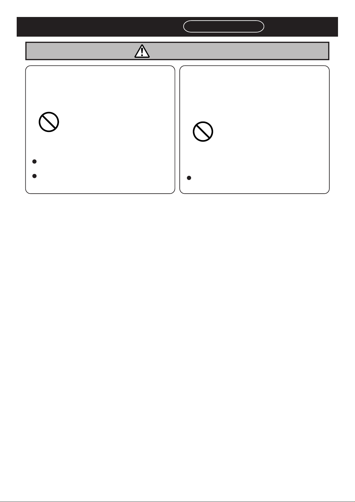
SAFETY PRECAUTIONS
WARNING
Be sure to observe
ONLY THE PERSON IN CHARGE OF
MAINTENANCE MUST REPAIR OR
ADJUST THE MACHINE.
The machine may be incorrectly repaired or adjusted, resulting in malfunction.
Have the machine repaired or adjusted by a
trained professional maintenance engineer.
Consult the manufacturer for training.
M08E
DO NOT PLACE YOUR HANDS OR
BODY INSIDE ACTIVE PART OF THE
MACHINE WHEN IT IS IN A SINGLE
STOP OR CYCLE ST OP CONDITION.
The machine has been stopped only temporarily .
You may be injured if the sensors are actuated and
the machine moves unexpectedly .
Turn OFF the servo switch before placing your
hands or body inside the active part.
M34EB
Page 16
193C-E-OMA00-A03-00
Page 17
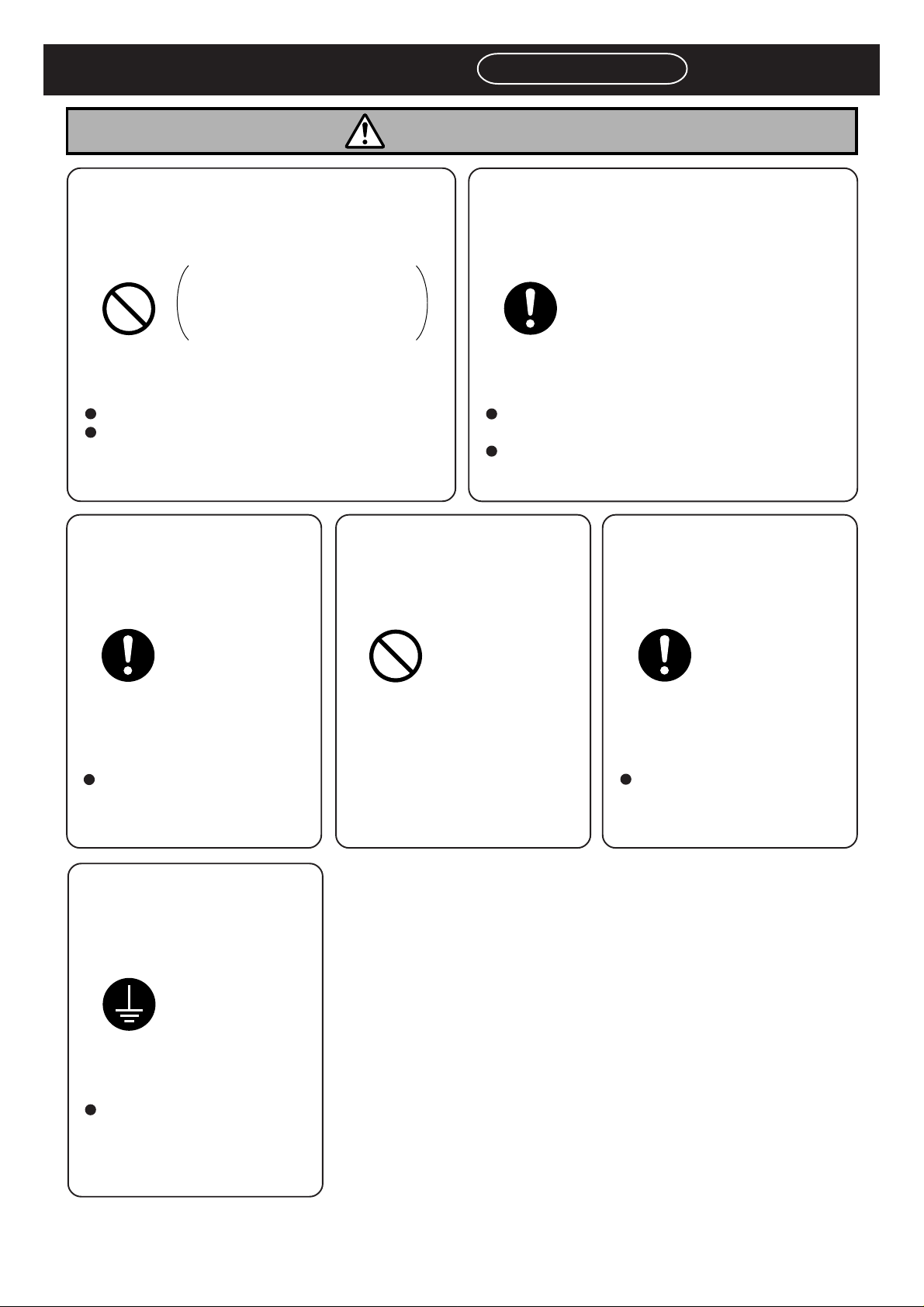
SAFETY PRECAUTIONS
WARNING
Be sure to observe
DO NOT DAMAGE POWER AND
OTHER CORDS OR PLUGS.
Never damage, remake, bring
close to heating appliances, bend
forcibly, twist, pull, put heavy
objects on, and bundle up.
Damaged cord and plug may cause electric shock,
short circuit or fire.
Hold the plug when plugging in or unplugging.
Cord and plug repairs should be attempted only
by the person competent to do the electrical
work, or contact the manufacturer.
M85E
FIRMLY INSERT THE
POWER AND OTHER
PLUGS.
DO NOT INSERT OR
REMOVE POWER AND
OTHER PLUGS BY
WET HAND.
PERIODICALLY REMOVE DUST
FROM POWER PLUG.
Dust on the plug may result in fire caused by
defective insulation because of moisture.
Pull out the power plug and wipe off dirt with dry
cloth.
If the machine is not going to be used for a long
period, turn off the breaker connected with the
machine.
M86E
USE THE SPECIALIZED OUTLET AND
BREAKER EXCLUSIVELY.
Imperfect plugging in may
cause fire because of electric
shock and generated heat.
Do not use the damaged plug
or loose outlet.
M87E
GROUND THE MACHINE PROPERLY.
There is a risk of an electric
shock or leak.
Consult a professional
electrical contractor.
If plugged in or unplugged by
wet hand, it may result in
electric shock.
M88E
If the breaker is shared between machines, it may cause
fire because of generated heat.
Check the dissipation power
in your Standard Specification before consulting an
electrical contractor.
M89EB
M06E
193C-E-OMA00-A03-01
Page 17
Page 18
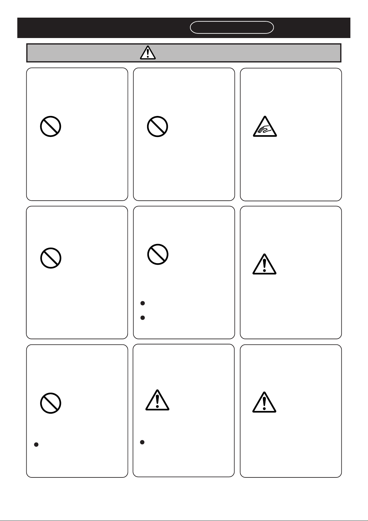
SAFETY PRECAUTIONS
CAUTION
Be sure to observe
IPA (ISOPROPYL ALCOHOL) USE ONLY.
The corrosion damage to the
hose may cause the machine to
catch fire.
L28EB
DO NOT CLIMB OR
RIDE ON THE MACHINE.
DO NOT PLACE ANY
OBJECT AROUND
EMERGENCY STOP
BUTTONS.
You will be unable to press a
button to stop the machine in
case of emergency .
M15E
DO NOT BLOCK OFF
THE OUTLET OR INLET OF THE FAN.
BE CAREFUL WITH
YOUR HANDS AND
FINGERS WHEN
CLOSING THE COVER.
Your hands or fingers may be
caught in the cover and injured.
M17EB
BE CAREFUL OF THE
MOTOR.
You may fall from or get caught
in the machine and get injured.
M18E
ONLY THE PERSON IN
CHARGE MUST
CHANGE THE DA T A.
The machine may runaway or
malfunction.
The data must be changed
only by a trained specialist
in charge.
The temperature inside of the
machine will rise and the
machine may malfunction.
Do not block off the outlet or
inlet of the fan.
Periodically clean the filters
of the outlet and inlet.
M20E
T AKE AWAY TOOLS
FROM THE INSIDE OF
THE MACHINE.
The machine may malfunction
as a result of a tool left inside.
Before operating the machine, verify that no tools are
left inside.
You may strike your head on
the protruding motor and be
injured.
M22EB
BE CAREFUL OF THE
PNEUMATIC PRESSURE UNIT.
You may stumble over the
pneumatic unit, break the glass
and be injured.
M23E
Page 18
M24EB
M26EB
193C-E-OMA00-A03-02
Page 19
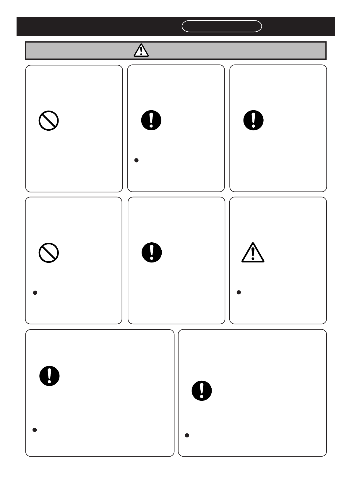
SAFETY PRECAUTIONS
CAUTION
Be sure to observe
DO NOT GIVE A
SHOCK TO THE ELECTRICAL EQUIPMENTS.
There is a risk of an electric
shock, leak or malfunction of
the machine.
M27E
DO NOT DISASSEMBLE THE CAMERA UNIT.
TURN ON THE
POWER BEFORE
SUPPLYING AIR.
Your hands or fingers may be
caught in the board support.
(1) Turn ON the power, then
(2) turn ON the air.
M29E
WEAR A PROTECTIVE
HA T AND GOGGLES
FOR MAINTENANCE
WORK.
USE A JIG TO FIT AND
REMOVE THE
SPRINGS.
Your hands or fingers may be
injured.
M30EB
BE CAREFUL IN HANDLING SOLDER
PASTE.
You may be injured or the
machine may break down.
If a breakdown occurs,
consult the manufacturer.
M41E
Your head or eyes may be
injured while performing maintenance work.
M44E
CARRY OUT PERIODIC MAINTENANCE AND INSPECTION.
If you fail to carry out periodic inspection and
maintenance, the machine cannot exhibit its true
performance. Also, it may break down or produce
defectives.
Periodic inspection and maintenance should be
carried out by a trained person in charge of
maintenance according to the instructions in
MAINTENANCE MANUAL.
M39E
193C-E-OMA00-A03-00
Some kinds of solder pastes
are harmful to the human body.
Follow the attached instruction manuals when using
solder pastes.
M74E
BEFORE PERFORMING AUT OMATIC
WIDTH ADJUSTMENT, BE SURE TO
VERIFY NO BOARDS OR OTHER
OBJECTS ARE ON THE CONVEYOR.
Boards or other objects may drop from the conveyor, causing damage to the boards or the machine.
If there are any boards or other objects on the
conveyor, turn OFF the servo switch and remove
them.
M36E
Page 19
Page 20

SAFETY PRECAUTIONS
CAUTION
BE CAREFUL IN HANDLING IPA (ISOPROPYL ALCOHOL).
Isopropyl alcohol is harmful to
the human body.
Wear the mask to avoid
organic odor when using
isopropyl alcohol.
M84EB
Be sure to observe
Page 20
193C-E-OMA00-A03-00
Page 21
SAFETY PRECAUTIONS
About Interlock
About Safety Cover Interlock
1. Basic feature of safety cover interlock
Before starting regular automatic production on this machine, close all safety covers.
Since a screen displays the message prompting you to supply a member when it needs to
be supplied, open the corresponding cover according to the member to be supplied and
then conduct the work.
If you accidentally open a safety cover during automatic production, the machine comes to
an emergency stop to ensure the safety of operators.
2. How to use servo switch
Since an operator needs to put the hands or part of body into the machine for the purpose
of model changeover or maintenance, the operating panel is equipped with the servo switch
in order to ensure on-the-job safety. When this servo switch is turned OFF, all of the drive
shafts of the machine will be inactive. For information about the operations above, refer to
the instruction manuals for each model.
Be sure to observe
About Key Switch for Maaintenance
1. Key switch for maintenance at our company
This switch, which is targeted for the technician belonging to our company or the commissioned maintenance technician, can release all of the safety cover interlocks. It is used for
such an extensive maintenance work as you cannot perform.
2. Feature of key switch for maintenance at our company
It is dangerous to use this maintenance key, because the safety cover interlock function will
be disabled and both the hardware and software judge that the safety covers are closed;
eventually, the safety features will be disabled in all modes.
If you need to put your hands or part of body into the machine while the safety cover interlock is released, be sure to turn OFF the servo switch and restrict each shaft action before
work.
3. Handling of maintenance key
We basically do not deliver this maintenance key to you.
If you should make a request for the maintenance key, we will deliver it after exchanging the
certificates of delivery acknowledgement.
In that case, we assume no responsibility for any accidents caused by your unsafe acts, for
example, releasing the interlock function.
Your safety manager should manage the maintenance key adequately.
193C-E-OMA00-A03-01
Page 21
Page 22

CLEANING SOLVENT FOR WET CLEANING
Recommended rate of mixed cleaning solvent :
Considering cleaning results, costs, availability, etc., IPA is recommended.
(However, handle IPA with great care because it may catch fire.)
Even if the IPA concentration is diluted to 4% by ethyl alcohol, the successful cleaning result can
still be obtained.
Solvent of 100% ethyl alcohol can be used, though the cleaning result gets worse a little.
Ethyl alcohol 96%
IPA (Isopropyl alcohol) 4%
Never use acetone.
The use of acetone may damage the solvent tube and the cleaning unit, resulting in the cleaning
solvent leakage.
Never use methanol (methyl alcohol).
The use of methanol breaks the solvent pump and disables its function.
Cleaning solvent may catch fire.
Handle with great care.
Use unused cleaning solvent.
Do not use water or the mixture of water and other cleaning solvent, as the
cleaning solvent.
Rust or change in quality of cleaning solvent may choke piping and damage the machine.
When using cleaning solvent other than ethyl alcohol and IPA, make
contact with us.
If using other cleaning solvent makes trouble, we do not guarantee it.
Wear the mask to avoid an organic odor during work.
IPA contains the substance harmful to the human body.
NOTICE
The following is recommended as the solvent which does not catch fire.
Name : FT - J630 (water solvent)
Manufacturer : Kuraray
Page 22
193C-E-OMA00-A04-00
Page 23
CLEANING SOLVENT FOR WET CLEANING
1
2
153C-E-TE008
deepS
s/mm
nrettaPmuucaV
oG04yrDNO
∗ However, the cleaning result gets worse.
Besides, it takes more time for the mask to
dry, so set the cleaning speed to 10mm/s
for Back of the second cleaning.
kcaB04yrDNO
oG02teWFFO
kcaB
01yrDNO
Optimum discharge amount of cleaning solvent for cleaning
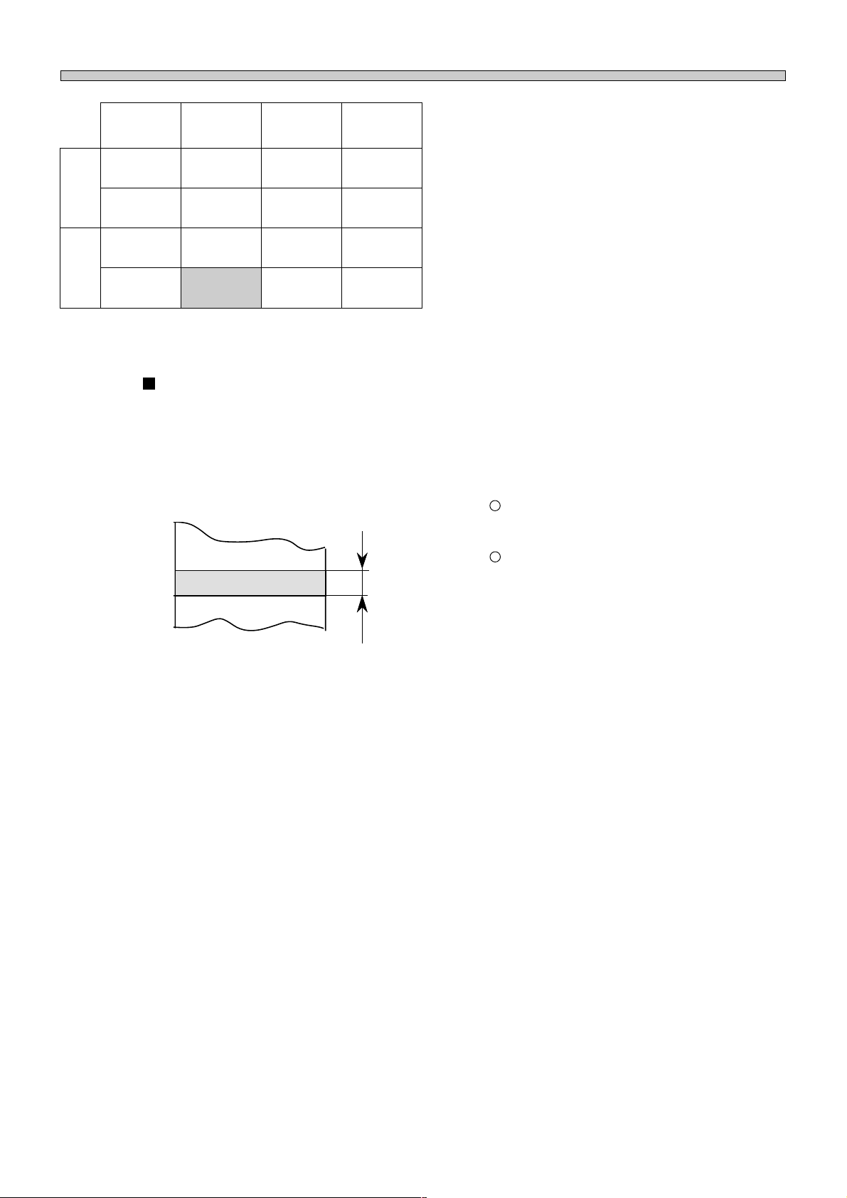
It is optimum to discharge the 35mm±5mm width of cleaning solvent onto the cleaning paper for the
wet cleaning.
Adjustment method : Adjust the discharge amount with the regulator on the back of the machine
(next to the cleaning solvent container).
(0.147 MPa to 0.196 MPa)
The increase of pressure makes the discharge amount larger.
35 mm ±5 mm
The decrease of pressure makes the discharge amount smaller.
193C-E-OMA00-A04-00
Page 23
Page 24

ABOUT DISPOSAL OF COMPONENTS CONTAINING MERCURY
NOTICE
This product has a fluorescent lamp that contains a small amount of mercury.
It also contains lead in some components. Disposal of these materials may be
regulated in your community due to environmental considerations.
For disposal or recycling information please contact your local authorities, or the
Electronics Industries Alliance.
Page 24
193C-E-OMA00-A04-00
Page 25
IDENTITY PLATE AND CAUTION LABEL
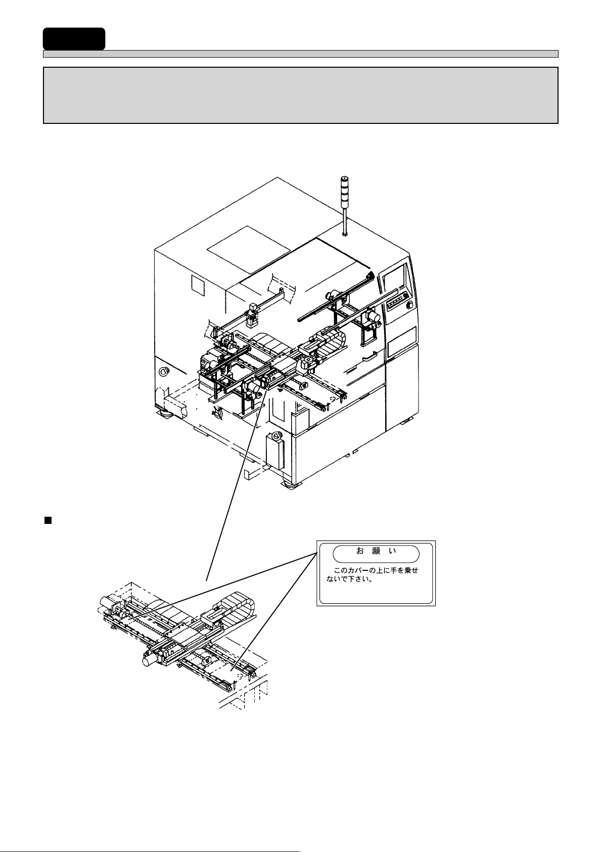
Both an identity plate and a caution label for this product are attached to the
machine. Operate and maintain the machine according to the instructions on
the label.
∗1 : Nameplates on X-Y table are for maintaining machine’s accuracy.
X-Y table
193C-AE00
∗1
ATTENTION
✄✄✄DON'T PUT YOUR HANDS
ON THIS COVER.
∗Two plates are attached to the Y-axis cover.
0799C2AA
193C-E-OMA00-A04-01
Page 25
Page 26
SERIAL PLATE
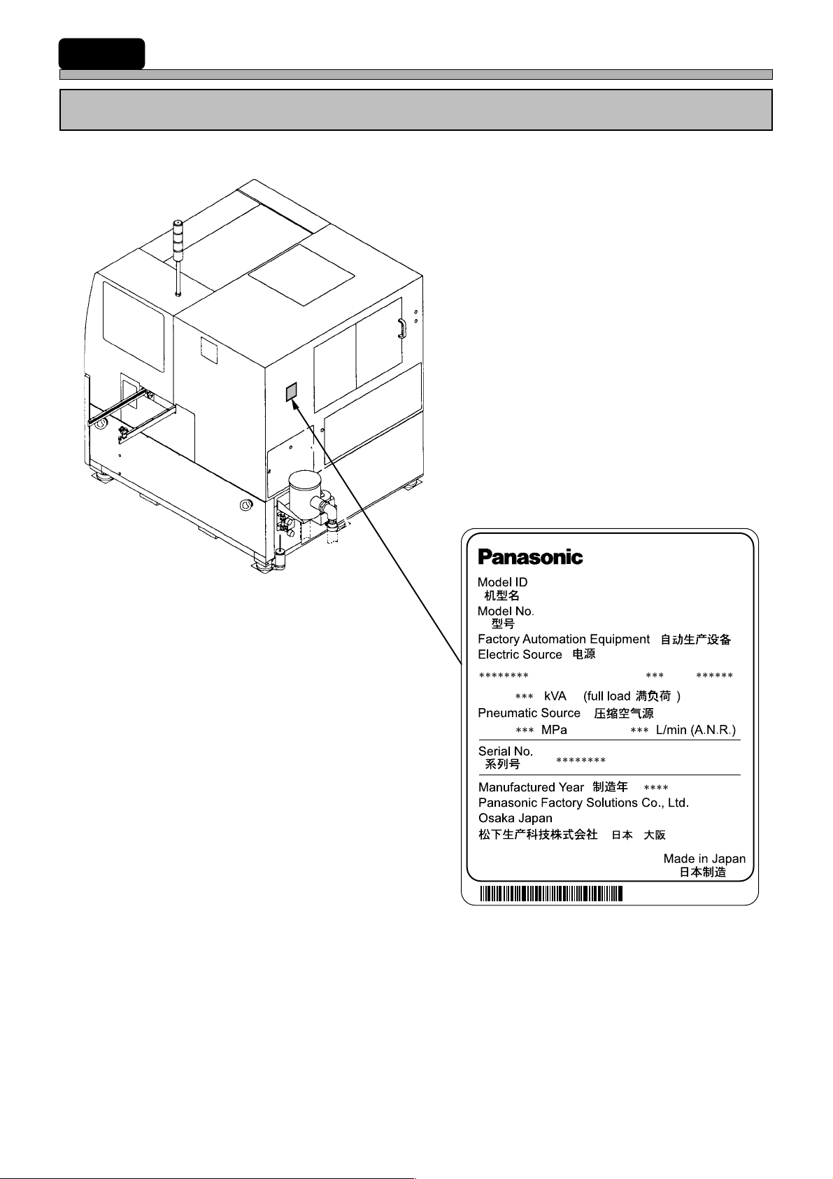
The serial plate attached to this machine indicates the model name and production number.
193C-AB00
SP22P-M
KXF-193C
Actual numbers are shown on the plate instead of ∗.
Page 26
193C-E-OMA00-A04-03
Page 27
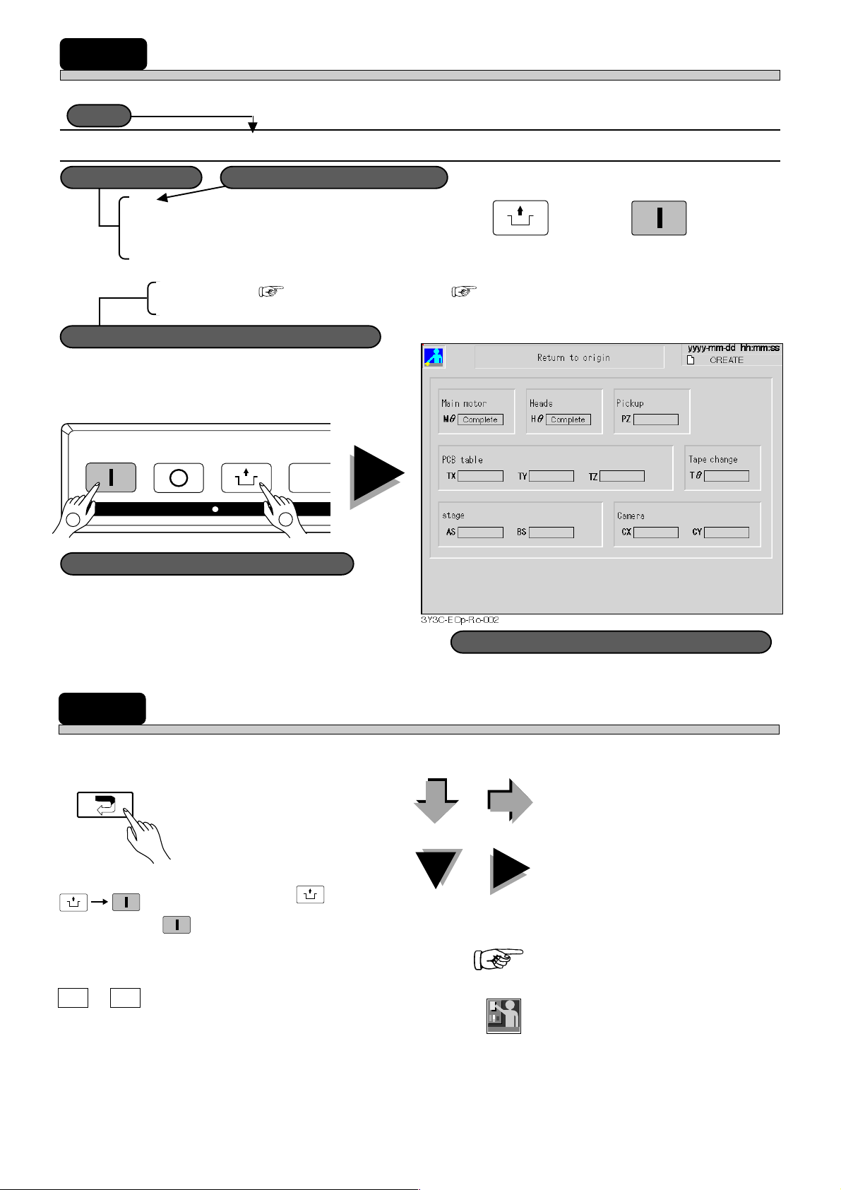
HOW TO SEE DESCRIPTION FOR OPERATION
Title
Title
Description is constructed basically as follows.
1-1-1 Starting Operation
Actual operation
Actual operation
Operating procedure number
Operating procedure number
1 After checking servo switch is ON, press
operating panel within 2 seconds.
Self diagnosis ( 3-2-2) → return to origin ( 3-2-3) are carried out. After that, when board is
transported in from previous process, production starts.
Supplementary description on operation
Supplementary description on operation
2
START
STOP
UNLOCK
KEY LOCK
STEP
1
UNLOCK
and then
START
on
Illustration showing actual operation
Illustration showing actual operation
MARKS USED IN THIS MANUAL
In this manual, the following marks are used for description.
: This shows pressing a key on
touch panel.
UNLOCK
START
: This means pressing
START
on operating panel within 2
seconds.
UNLOCK
and then
Screen displayed after actual operation
Screen displayed after actual operation
: These show operation flow.
: These show operation (cause) and
its effect.
: This shows the item to refer.
A B
+
193C-E-OMA00-A04-00
: This means pressing the key B
holding the key A.
: This shows operation by engineers.
Engineer
Page 27
Page 28

= MEMO =
Page 28
193C-E-OMA00-A04-01
Page 29

Chapter 1
GENERAL DESCRIPTION
GENERAL DESCRIPTION
Names and mechanism of each unit
This chapter describes names of each unit by using front view , rear view, perspective
view, etc.
This chapter also describes printing mechanism by using pictures and simple illustrations.
193C-E-OMA01-A01-00
193C-AA00
Page 1-1
Page 30
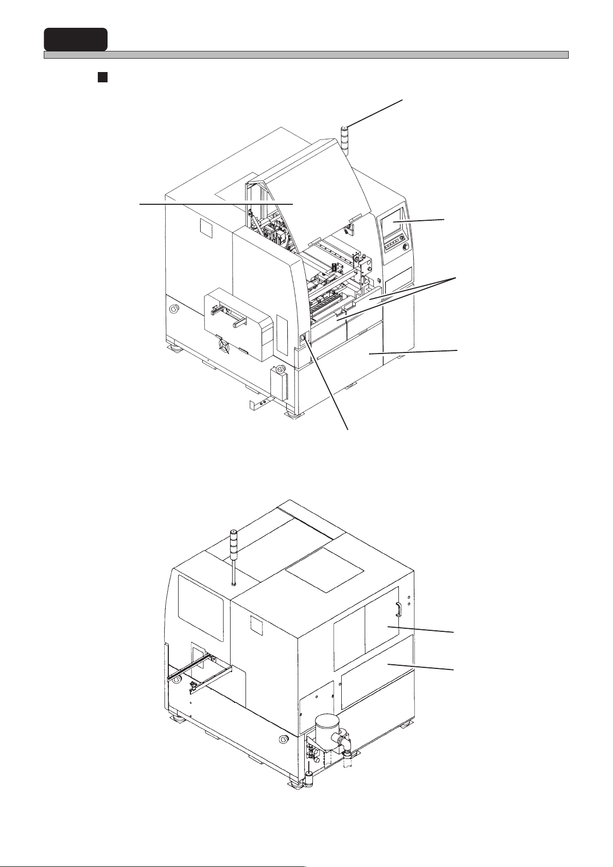
1-1 Names and Mechanism of Each Unit
External view
[Front view]
Front safety cover
Status indicator
(3-color indicator light)
Front panel
Center safety cover
Control box
(Inside the cover)
193C-AC02
[Rear view]
Power supply switch
Rear safety cover
Rear cover
Page 1-2
193C-AB00
193C-E-OMA01-A01-00
Page 31
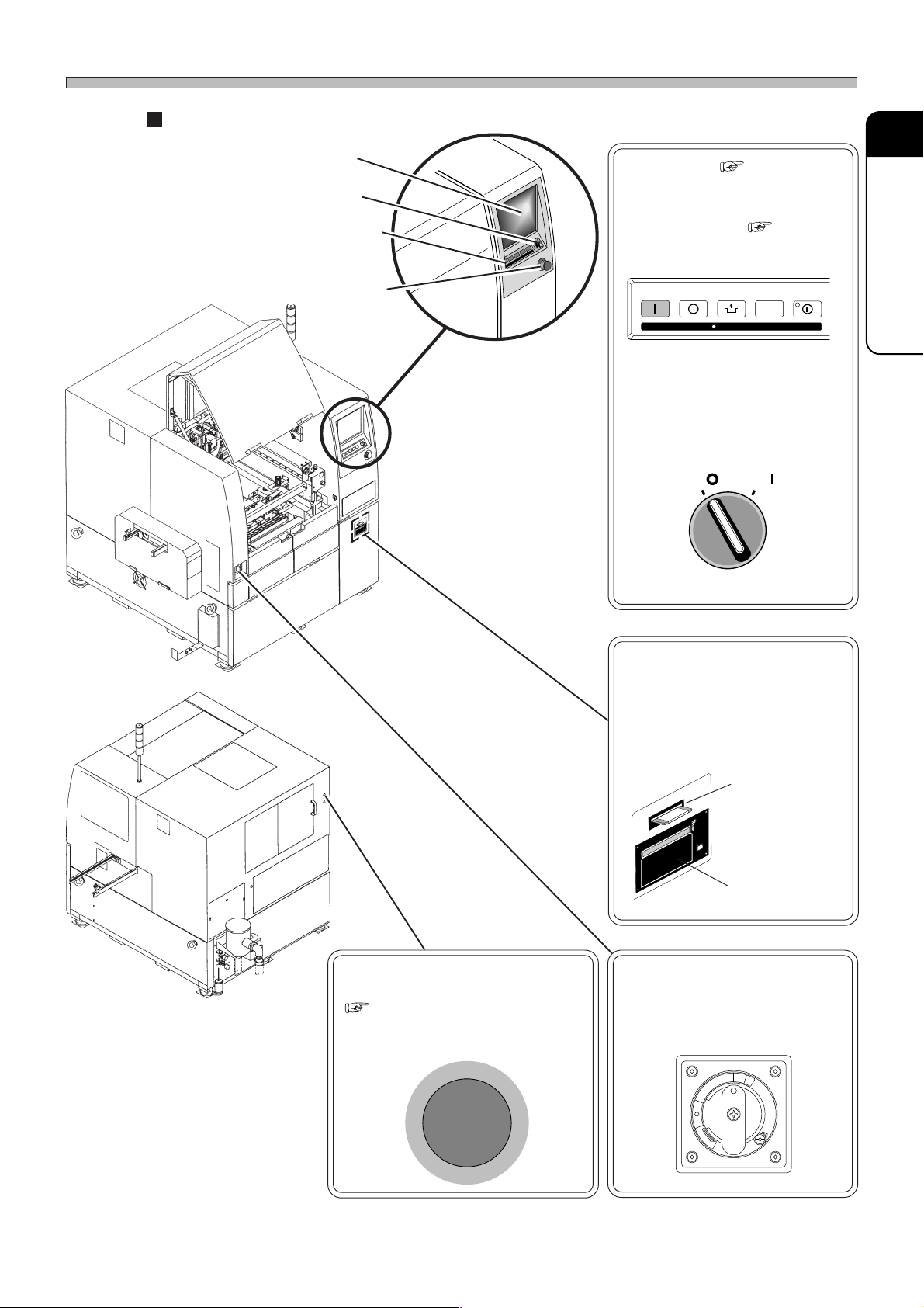
Operating units
Touch panel
Servo switch
Names and Mechanism of Each Unit
Touch panel ( 2-2)
Used to operate machine.
1
GENERAL DESCRIPTION
193C-AC02
Operating panel
Emergency
stop button
(Inside the cover)
Operating panel ( 2-1)
Used to start machine, stop it,
and so on.
START
STOP
UNLOCK
KEY LOCK
STEP SELECT
Servo switch
(Two in total)
Used for ON/OFF power switch
of servo system motor.
SERVO
OFF ( )
ON ( )
Floppy disk drive
Used to write and read programming data.
Printer
Used to print hard copy and
production information.
193C-AB00
193C-E-OMA01-A01-00
Emergency stop button
(Two in total)
( SAFETY PRECAUTIONS)
When you press this button, machine comes to an emergent stop.
G
E
R
N
E
M
E
S
C
Y
P
T
O
Floppy disk
drive
Printer
Power supply switch
Used for ON/OFF power switch
of machine.
O
N
P
I
R
T
F
F
O
T
E
S
E
R
E
S
A
E
L
E
R
Page 1-3
Page 32
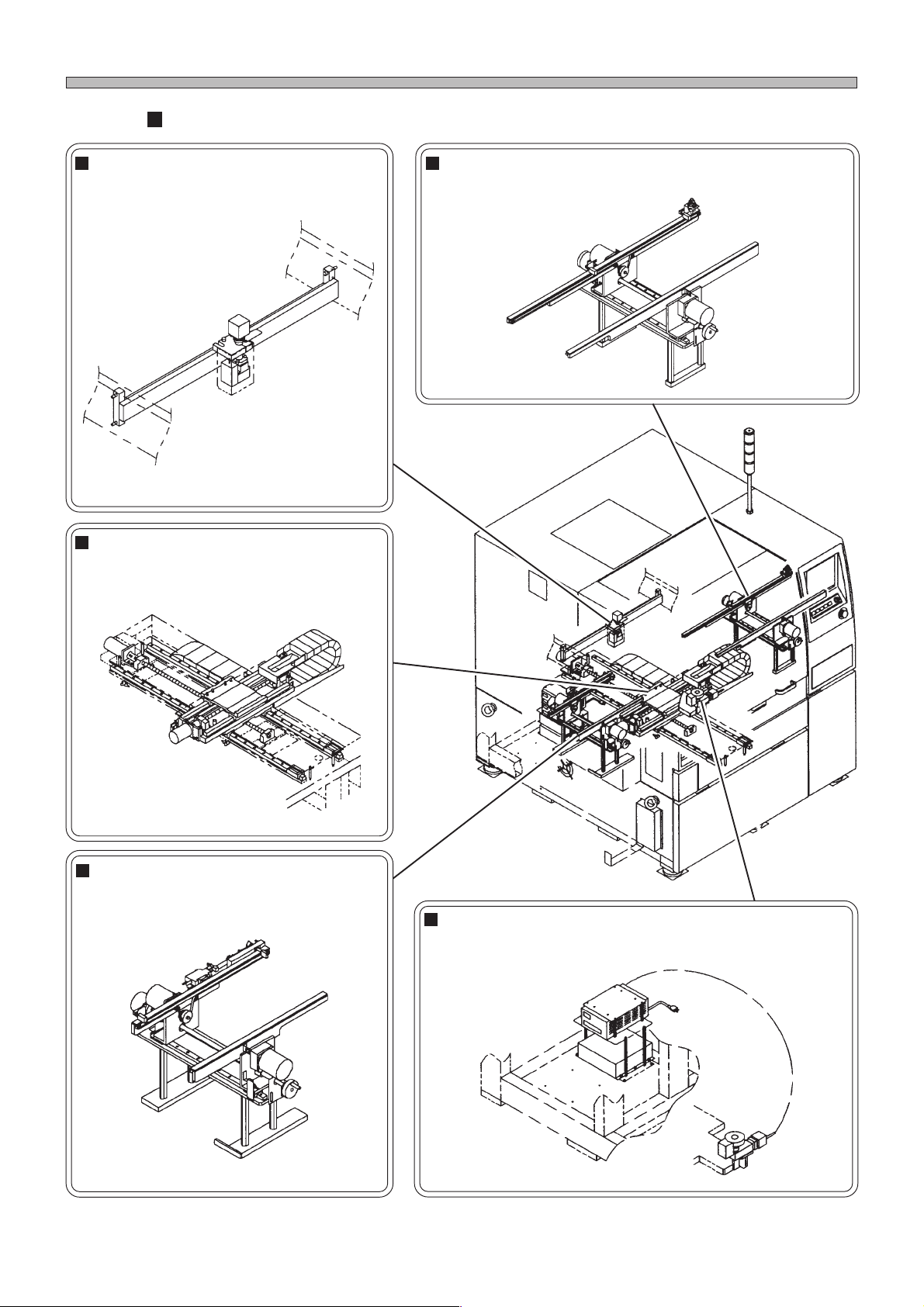
Names and Mechanism of Each Unit
Main units (Front view 1/2)
Board recognition unit
This unit recognizes board recognition
marks to correct the position of boards.
16EQC2AA
X-Y table
This table moves board positioning &
lifting unit.
Right conveyor
This conveyor transports boards out to the next process.
11DKC2AA
0799C2AA
Left conveyor
This conveyor transports boards in from
the previous process.
11DJC2AA
Page 1-4
193C-AE00
Mask recognition unit
This unit recognizes and corrects masks after they are
changed.
1766C0AA
193C-E-OMA01-A01-00
Page 33
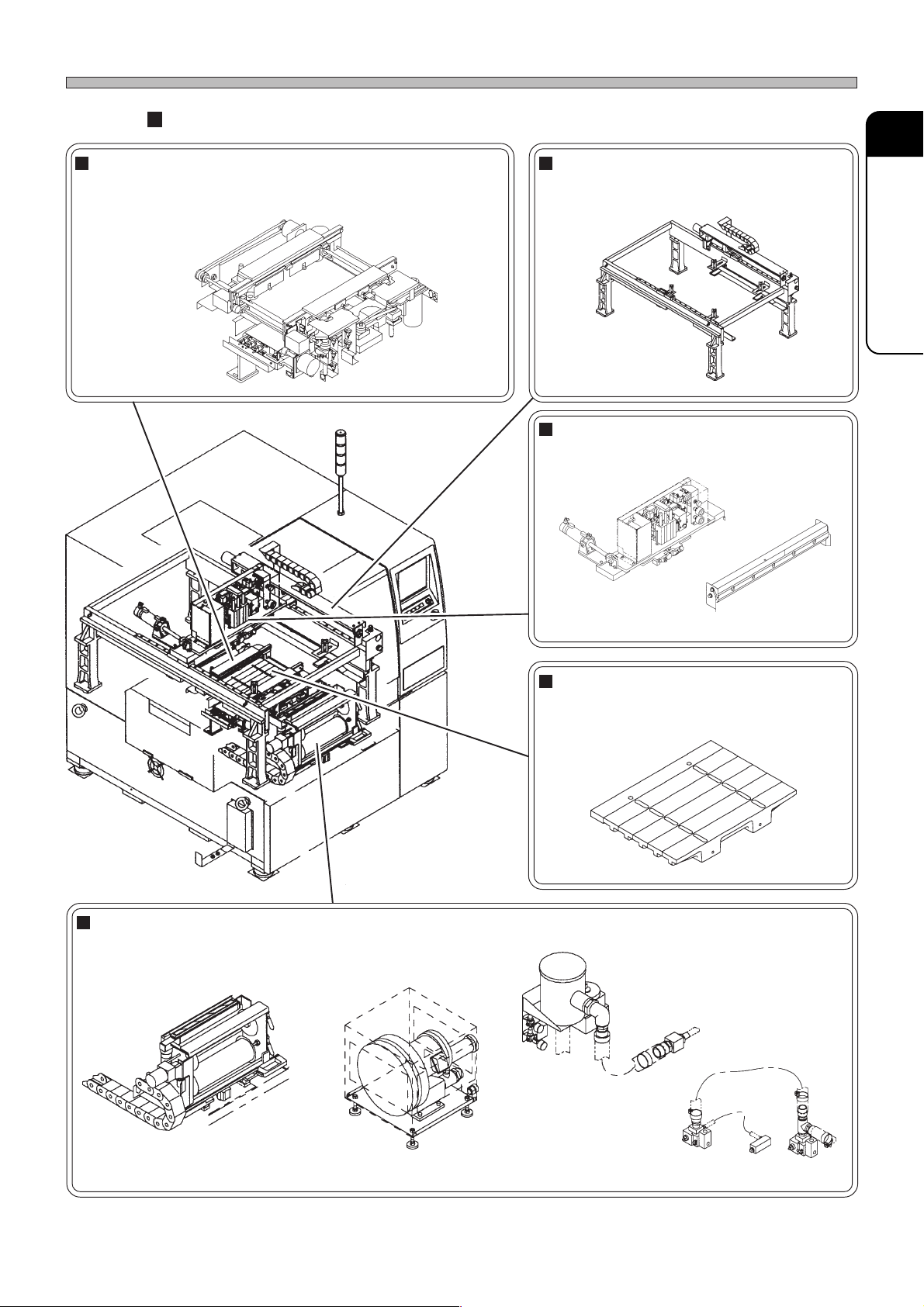
Main units (Front view 2/2)
Board positioning & lifting unit
This unit positions boards by using edge reference and
carries out the mask release control at the printing position.
Names and Mechanism of Each Unit
Screen printing head
This unit screen-prints boards.
1
GENERAL DESCRIPTION
18A5C2AA
1937C2AA
Squeegee head
This unit screen-prints boards.
1938C2AA
15D7C1AA
Board support unit
This unit supports boards through pins,
blocks, the suction plate, etc.
193C-AD01
Automatic mask cleaning
This unit cleans the back of mask.
1939C2AA 1939C2AB
193C-E-OMA01-A01-00
1054C5AA
1939C2AC
1939C2AD
Page 1-5
Page 34
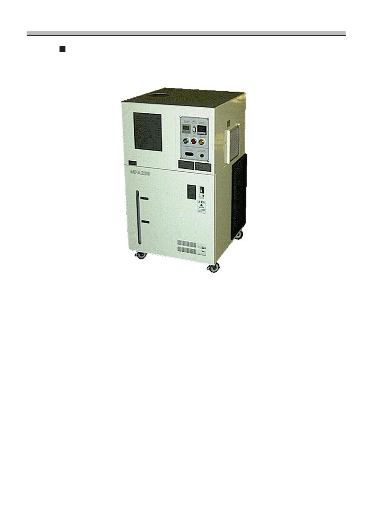
Names and Mechanism of Each Unit
Atmospheric temperature control unit (option)
To maintain the printing precision, this unit controls the temperature of solder paste on mask.
193C-024P
Page 1-6
193C-E-OMA01-A01-00
Page 35
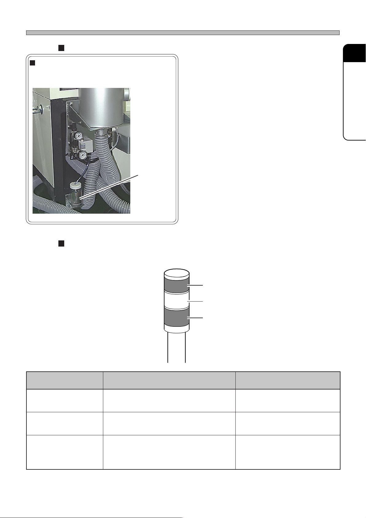
Others
Drain bottle
This bottle saves drainage from air plumbing and
regulator system.
Drain bottle
Names and Mechanism of Each Unit
1
GENERAL DESCRIPTION
193C-025P
Status indicator (3-color indicator light)
This light indicates operating conditions of machine. If any trouble occurs during operation, it warns
you by a buzzer.
Red
Y ellow
Green
ecnaraeppA,roloC gninaeM esuaC
193C-040TE
193C-E-OMA01-A01-00
tiL,neerG
gniknilB,wolleY
gniknilB,deR
noitarepo
gninnurgnitsujda
)potsycnegremE(
enihcamronoitarepocitamotuagniruD
eunitnocnacuoyhcihw,gninrawroelbuorT
noitarepoeunitnoctonnacuoyhcihw,elbuorT
yllamrongninnuR
potselcyC/etaidemmI
slairetamfokcaL
potsycnegremE•
.cte,rotomfoelbuorttfahS•
nwoderusserpriA•
elbuorttropsnartdraoB•
Page 1-7
Page 36

1-2 Printing Mechanism
This section describes printing mechanism in due order.
Transporting
board in
1
Board from the previous
process is set on printing
stage to make machine ready
for printing.
2
Printing solder
1
From the previous process to left
conveyor
193C-012P
6
Printing stage moves to the
printing position.
2
From left conveyor to printing
stage
193C-013P
When printing stage is not occupied,
board is transported in there.
7
Lifter rises up to the mask,
then solder is printed by
squeegee.
Solder is printed on board.
3
Cleaning mask
Solder on the back of mask is
removed.
193C-017P
(Normally , mask is set. So a board
is hidden under the mask.)
9
Cleaning unit moves to the
cleaning position.
2
1
193C-018P
(Normally, mask is set. So a board
is hidden under the mask.)
10
Cleaning mask
Page 1-8
193C-020P
Printing stage connects with
cleaning unit, and moves to the
cleaning position.
193C-021P
Suction nozzle rises up, and cleans
the mask.
193C-E-OMA01-A01-00
Page 37
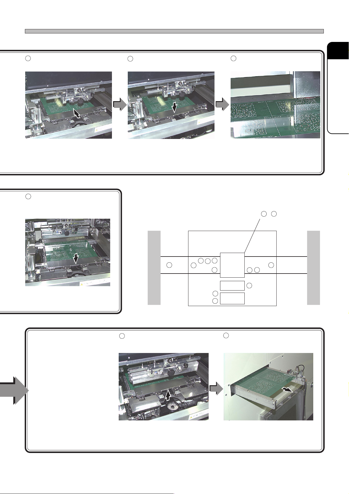
Printing Mechanism
3
Positioning a board
193C-014P
Board is fixed in Y direction, and the
support rises up.
(Normally, mask is set. So a board
is hidden under the mask.)
8
Lifter lowers to the transport
height from the mask.
4
Lifter lowers to the printing
height.
193C-015P
5
Recognizing a board
193C-016P
Board recognition mark is captured
by board camera, and the position
of the board is corrected to the
calculated accurate position.
3
~5 Printing stage
1
GENERAL DESCRIPTION
193C-019P
(Normally , mask is set. So a board
is hidden under the mask.)
Transporting
4
board out
Board is transported out of
printing stage to the next
process.
Previous process
1
Left
conveyor
11
Printing stage rises up to the
transport height, then release
the board.
Next process
5
3
4
2
6
Squeegee
10
Cleaning
9
unit.
12
8
7
From printing stage to right
12
11
Right
conveyor
conveyor
193C-E-OMA01-A01-00
193C-022P
(Normally , mask is set. So a board
is hidden under the mask.)
193C-023P
After that, when the signal of OK to
accept comes from the next process,
board is transported to the next process.
Page 1-9
Page 38
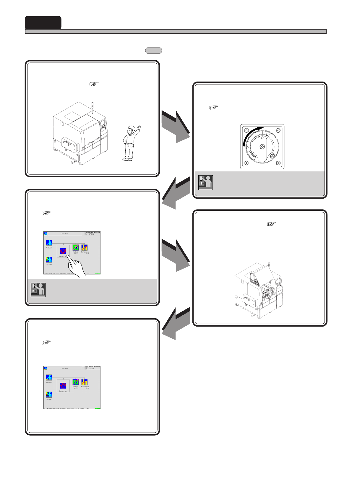
1-3 Production Work Flow
This section describes operator’s production work.
∗ Entrust the operation inside to engineer.
1 Preparations
• Start-up inspection ( 3-1-1 Start-up
Inspection)
2 Starting up machine
193C-AA00
3 Starting production
( 3-2-1 Starting Operation)
• Operate to produce.
Preparation
OK
Production starts.
( 3-1-3 Starting up Machine)
• Turn on power supply switch to start up
machine.
O
N
P
I
R
Power ON
T
F
F
O
T
E
S
E
R
E
S
A
E
L
E
R
Adjust equipment if it is in bad condition.
Engineer
4 Supplying materials ( Chapter 6
SETTING PRODUCTION MATERIALS)
• Supply the solder, the solvent and the cleaning paper which are run out.
File operation (loading production data, etc.)
Troubleshooting of board recognition error,
Engineer
etc.
5 Finishing production
( 3-5-2 Finishing Machine)
• Operate to finish production.
Production finishes.
193C-AC02
Page 1-10
193C-E-OMA01-A01-00
Page 39
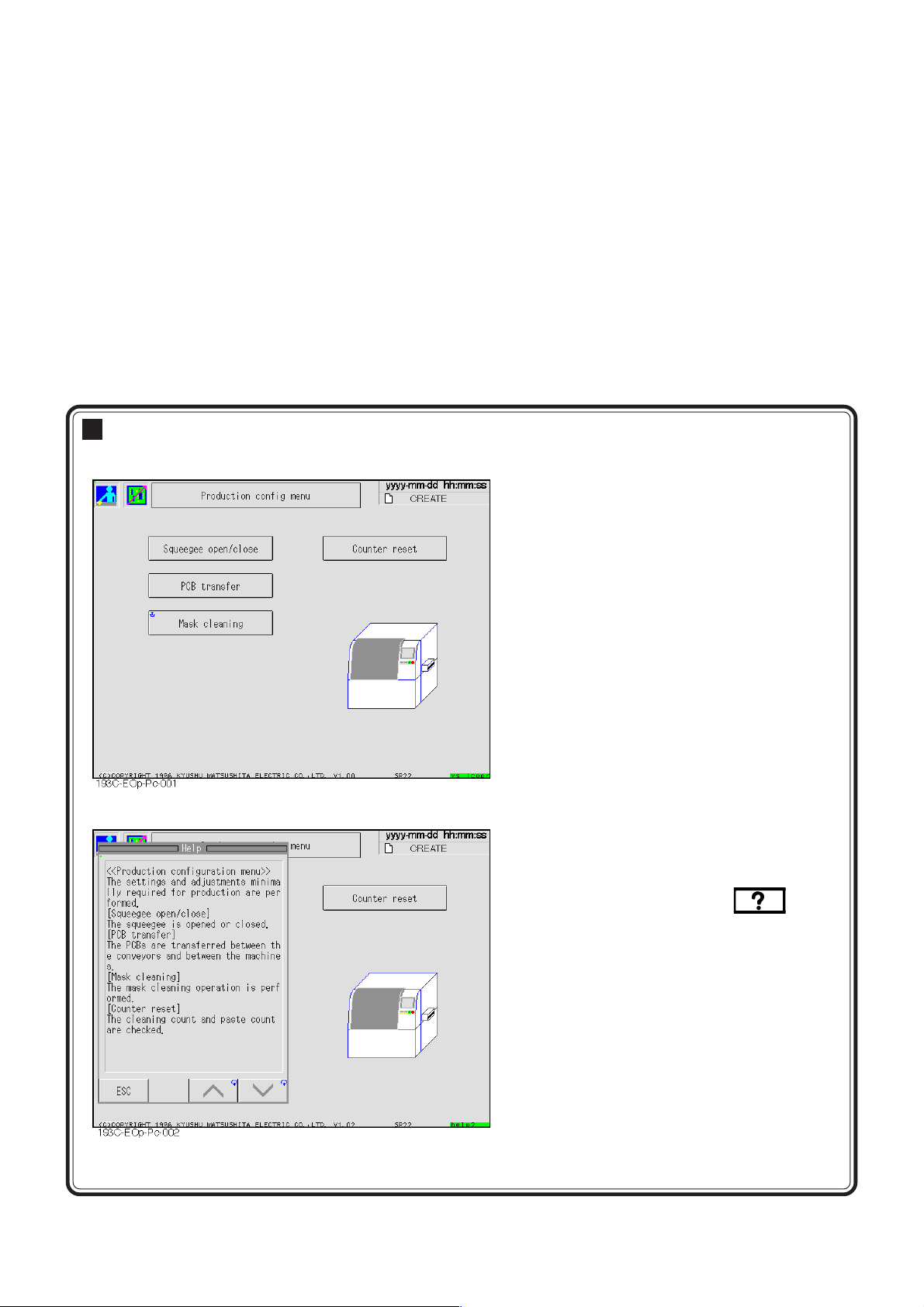
Chapter 2
BASIC OPERATION
BASIC OPERATION
Easy operation by using touch panel
• You can operate this machine mostly by using LCD color touch panel.
You can choose item by softly pressing an
icon or a button on screen.
• When you are at a loss, refer to Help.
193C-EOp-Pc-002
193C-E-OMA02-A01-00
When you want to know description of screen
and operation method, press below
the screen to display description of the
current screen.
Page 2-1
Page 40

2-1 Operating Panel
This section describes operating area and basic operation of machine.
START
START
UNLOCK
STOP
UNLOCK STEP SELECT
KEY LOCK
hctiwS noitcnuF
STOP
SERVO
OFF ( )
ON ( )
E
M
E
S
G
E
R
N
C
Y
P
T
O
.potsyraropmetaretfatiemuserotdnanoitcudorptratsotdesusisihT
.tuognitnirppotsdna)potsetaidemmI(yliraropmetnoitcudorppotsotdesusisihT
.noitneverpregnadrofhctiwssihthtiwdesueraenihcamkrowotsehctiwsehT
193C-018TE
STEP
SELECT
KEY LOCK
SERVO
M
E
S
G
R
T
ON ( )
E
N
C
P
O
Y
OFF ( )
E
.noitcudorpgnirud)enoybenoecneuqesevomot(noitompetsrofdesusisihT
.enihcamsihtnodesutonsisihT
.cte,FFOOVRESotgniwodilavnisilenapgnitarepofoesuehtnehwsthgilpmaL
)hctiwsovreS(OVRES
trapelibomotnisdnahruoytresniuoynehW.rotomehtrofhctiwsrewopasisihT
NOnrut,noitcudorptratsuoynehW.hctiwsehtFFOnrutoteruseb,enihcamfo
.edisraerehtnodnalenapgnitareponosehctiwsovresehthtob
)nottubpotsycnegremE(POTSYCNEGREME
tillup,teseroT.potstnegremenaotsemocenihcam,nottubsihtsserpuoynehW
.drawrof
[× ]2
Page 2-2
193C-E-OMA02-A01-00
Page 41
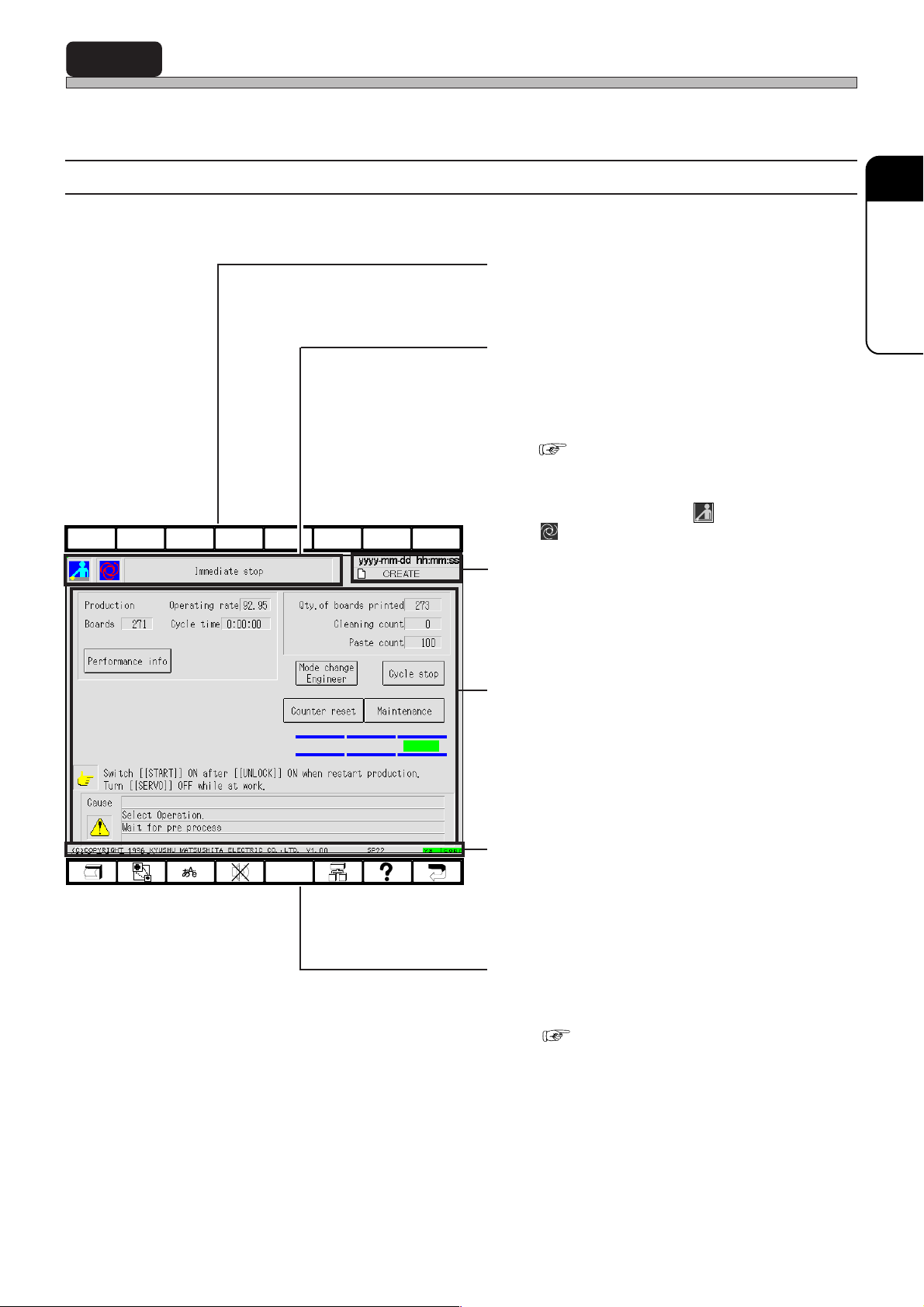
2-2 Touch Panel
This machine is operated by using touch panel and operating panel. This section describes basic
operation of touch panel.
2-2-1 Touch Panel Configuration
Touch panel configuration is as follows.
F 1F 2F 3F 4F 5F 6F 7F 8
2
BASIC OPERA TION
a) Upper function keys
These are not used now. Even if you press
them, they are invalid.
b) Hierarchy, mode and menu name
display area
State of the current displayed screen is dis-
played by icon and item name.
The same icon as main menu is displayed.
( 2-4 Main Menu)
E.g.) The screen as shown left
This shows machine has come to an immediate
stop in operator mode ( ) during production
( ).
c) Date, time and data name display area
Present date, time and data name are dis-
played.
193C-EOp-PrIs-001
d) State display, switches and messages
area
State of machine, messages and switches for
operation are displayed.
e) Copyright, system version and screen
name display area
Copyright of the screen, system version and
name of displayed screen are displayed.
f) Lower function keys
These are allotted the functions to be used
frequently .
( 2-2-3 Function Keys)
193C-E-OMA02-A01-01
Page 2-3
Page 42
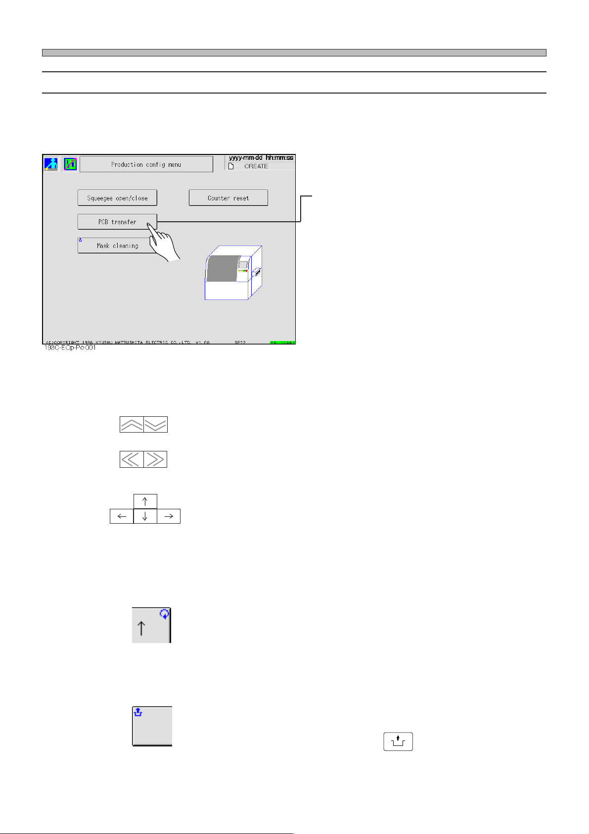
Touch Panel
2-2-2 Switch Types and Operation Method
You can operate this machine mostly by pressing a switch on screen softly.
a) Selection switches
• Choosing item
1) Press the item you want to choose
with your finger.
The screen of the chosen item is displayed.
Main menu icons belong to selection switches.
b) Arrow switches
------- Page turning switches
(Vertical direction)
(Horizontal direction)
------- Move switches
c) Mark on switch
------- Repeat mark (at the upper right)
Page of displayed screen is turned.
Cursor moves in the direction of the arrow .
(Not all the cursors are arranged as shown left.)
While the switch with this mark is pressed, its function continues to be
executed.
Page 2-4
------- Unlock mark (at the upper left)
The switch with this mark is used while is pressed.
UNLOCK
193C-E-OMA02-A01-00
Page 43
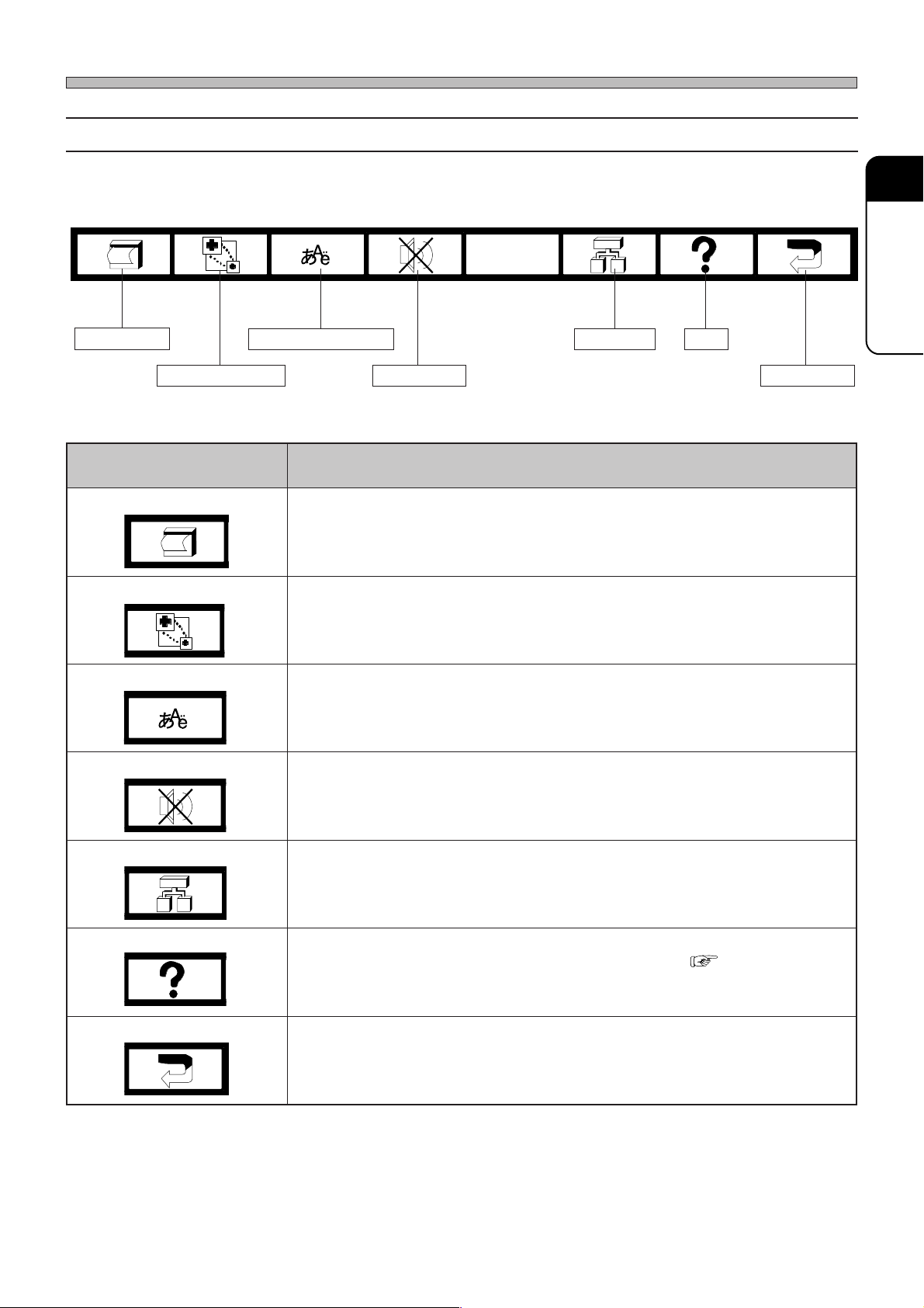
2-2-3 Function Keys
Touch Panel
Screen print
Function keys on lower part of screen are allotted the following functions. When you press the key, it
functions.
Language selection
Superimposition
Buzzer stop
Tree jump Help
Return key
yeknoitcnuF noitcnuF
tnirpneercS
.neercsfoypocdrahtnirpotdesU
noitisopmirepuS
ezis-lluf,ecneuqesnirevosegnahcneercsnoitingocer,desserp → ,ezis-2/1
,tfelreppu → ,ezis-2/1,thgirreppu→ ,thgirrewol,ezis-2/1 →,tfelrewol,ezis-2/1
.noiteled
siyeksihtemityrevE.lenaphcuotnodesopmirepussineercsnoitingoceR
2
BASIC OPERA TION
pmujeerT
pleH
yeknruteR
3Y3C-109TE
noitcelesegaugnaL
.yletaidemmilenaphcuotnohsilgnEdnaesenapaJneewtebtcelesnacuoY
potsrezzuB
.gnidnuossitinehwrezzubapotsotdesU
hcihw,deyalpsidsineercseertunem,neercsynatayeksihtsserpuoynehW
.neercsunemnesohcehtotgnipmujselbane
pleH3-2(.deyalpsidsineercsdeyalpsidtnerrucehtfonoitpircseD
)noitcnuF
.enognidecerpehtotsnruterneercS
193C-E-OMA02-A01-00
Page 2-5
Page 44
Touch Panel
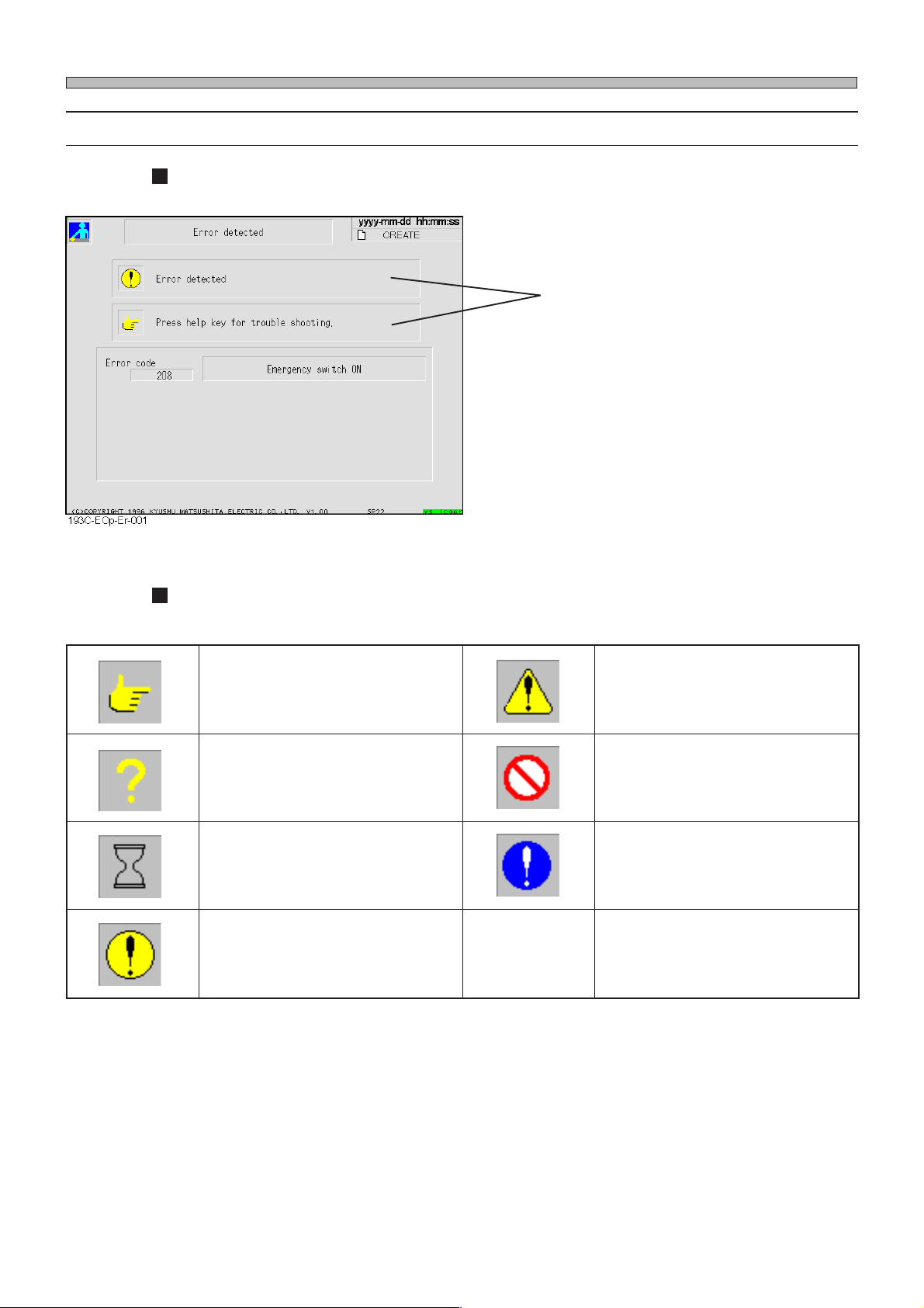
2-2-4 Messages
Message to operator is displayed inside square frame.
Message
3Y3C-003TE
Message icons
The following icons are at the head of messages to show message type .
egassemnoitcurtsnI
))dnah(kramwolleY(
egassemyriuqnI
))?(kramwolleY(
egassemgnitiawemiT
))ssalgdnas(kramkcalB(
egassemrorrE
nidnuorgwolleyanokramkcalB(
))!(emarfkcalb
egassemnoituac,gninraw,regnaD
nidnuorgwolleyanokramkcalB(
))!(emarfkcalb
egassemnoitibihorP
dnuorgetihwanoenildetnalsdeR(
)emarfderni
egassemnoislupmoC
))!(dnuorgeulbanokrametihW(
Page 2-6
193C-E-OMA02-A01-00
Page 45
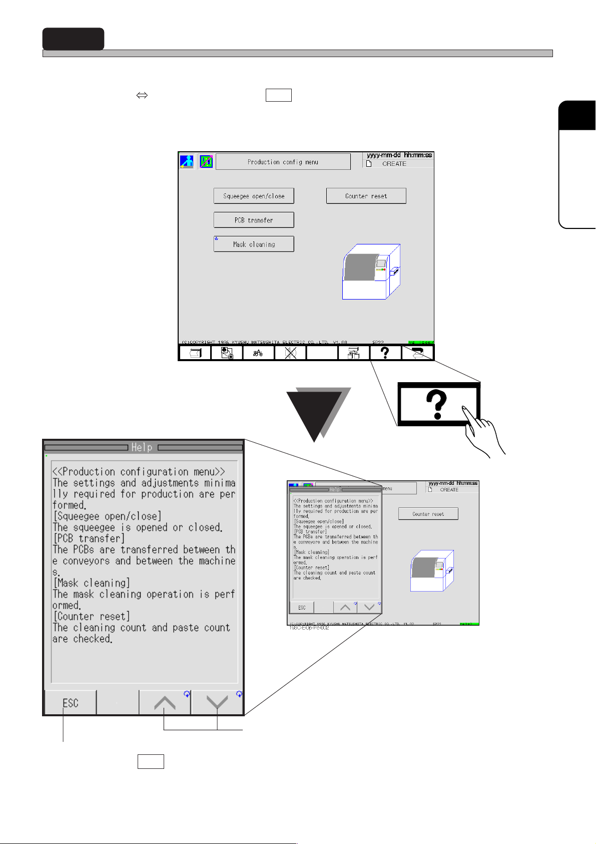
2-3 Help Function
When you want to know how to operate, press help function key to display description and operation method of the screen. Every time it is pressed, the position of message changes alternately
(Left Right). To exit Help, press ESC .
Help messages are displayed according to the screen menu such as during production, during
stop, errors, etc.
193C-EOp-Pc-001
2
BASIC OPERA TION
193C-EOp-Pc-002
Exit
To exit Help, press ESC .
193C-E-OMA02-A01-00
Scroll
Screen is scrolled in the direction of the arrow.
Page 2-7
Page 46

2-4 Main Menu
2-4-1 Contents of Main Menu
Main menu is an initial screen of this machine for each operation.
Inspection time display area
When daily inspection time is drawing on (to 90% of
its cycle), the message is displayed in yellow.
When inspection time has passed, the message is
displayed in red.
When the message is displayed, ask engineer for
inspection.
Icon switches
When you press a key , the menu screen represented
by the key is displayed.
193C-019TE
metI noitcnuF
noitcudorP•
.noitcudorprofdesU
Production
sgnittesnoitcudorP•
.noitcudorprofetisiuqersgnittescisabrofdesU
Product
config
noitamrofninoitcudorP•
.noitamrofninoitcudorpteserdnayalpsidotdesU
Performance
info
reenignE•
).drowssapdeenuoY(
Engineer
.sreenigneroflaunamgnitarepoees
.edomreenigneotdegnahcsiedomrotarepO
,edomreenignenidohtemnoitarepotuobanoitamrofniroF
Page 2-8
193C-E-OMA02-A01-00
Page 47

Chapter 3
DAILY PRODUCTION
DAILY PRODUCTION
Safety during production
• Do not put your hands into machine while it is running. Machine is running in the
following state.
1. While machine is running actually
2. During a stop to wait for board
3. During a temporary stop
Depending on circumstances, machine may run unexpectedly, especially “2. During a
stop to wait for board” and “3. During a temporary stop.”
When you put your hands into machine, make sure servo switch is OFF or power
supply is OFF.
193C-E-OMA03-A01-00
Page 3-1
Page 48
3-1 Before Production
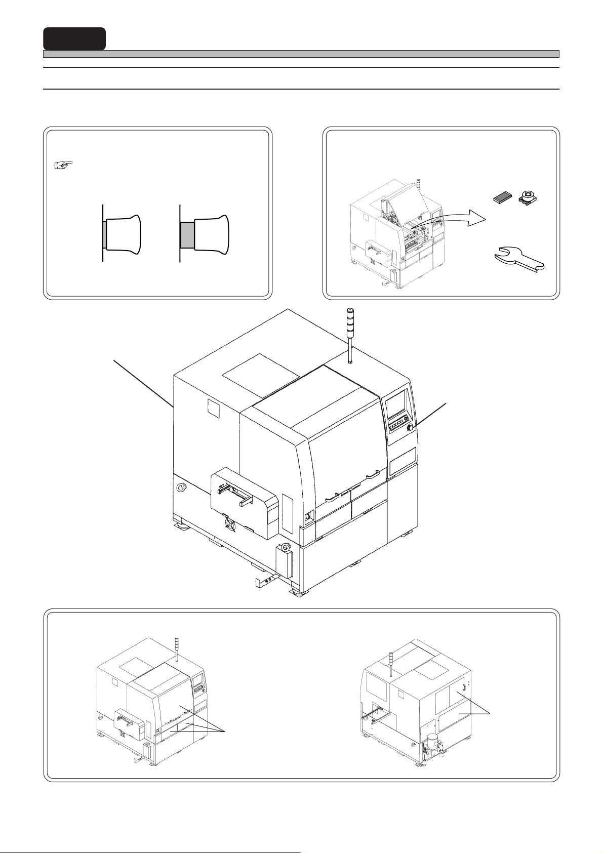
3-1-1 Start-up Inspection
Before starting operation, check the following points.
Are emergency buttons reset?
(×2)
( SAFETY PRECAUTIONS)
State of emergency stop
State of reset
Emergency stop button
Are there any foreign bodies on conveyors and
board positioning & lifting unit?
Chips
433C-037E
Tools
193C-AC02
433C-038E
Emergency stop button
Are all the covers closed?
193C-AA00
Page 3-2
193C-AA00
Rear side
Front side
193C-AB00
193C-E-OMA03-A01-00
Page 49
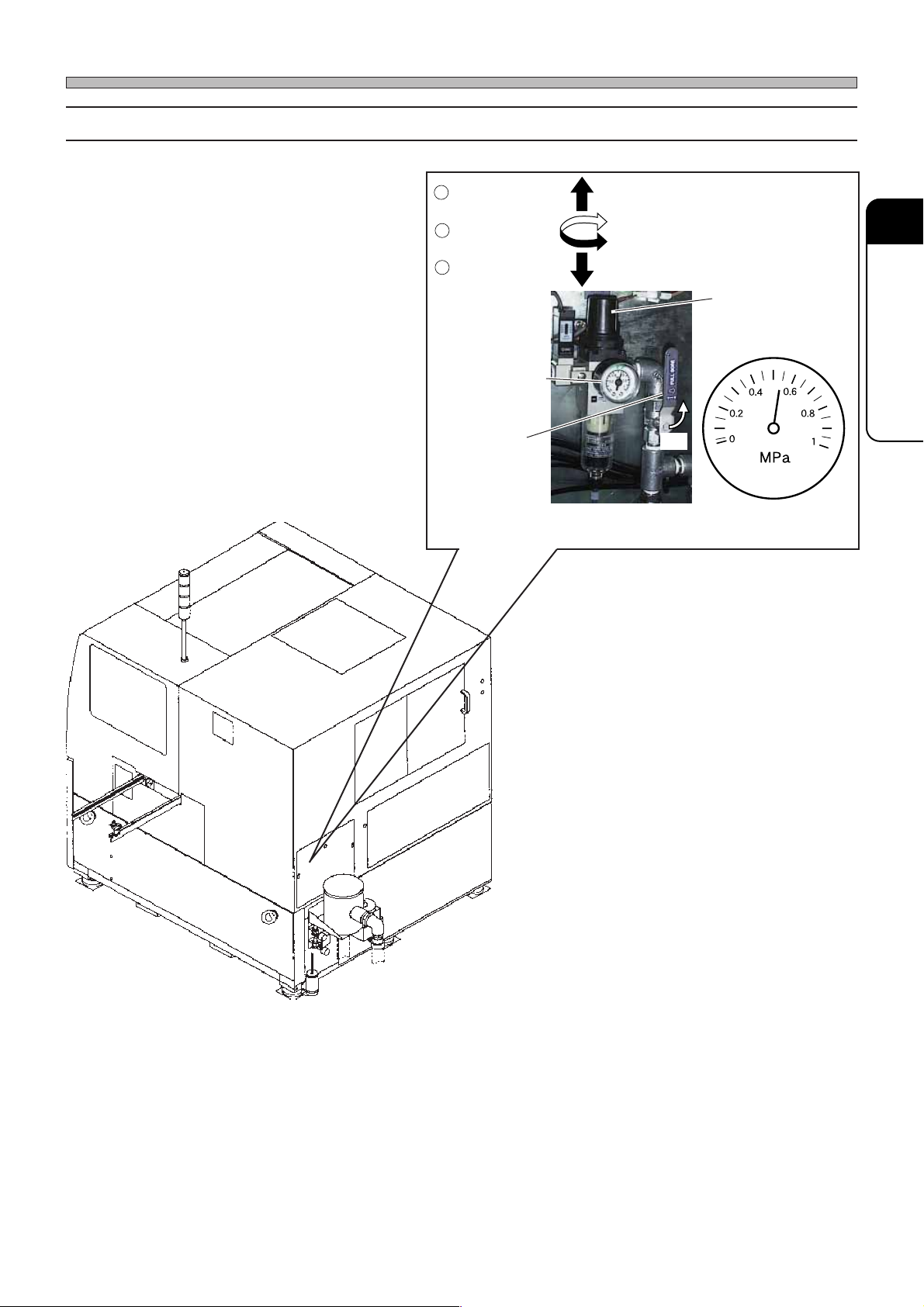
3-1-2 Checking Air Pressure
Make sure a pressure gauge shows
0.49 MPa or above.
1
Unlock a valve.
Before Production
∗ Make sure a lever is ON.
∗ If air pressure is improper, turn the valve to
adjust.
2
Adjust it.
3
Lock it.
Pressure gauge
Lever
To turn it ON,
throw it down.
3
DAILY PRODUCTION
Valve
ON
193C-007P
193C-AB00
193C-E-OMA03-A01-02
Page 3-3
Page 50
Before Production
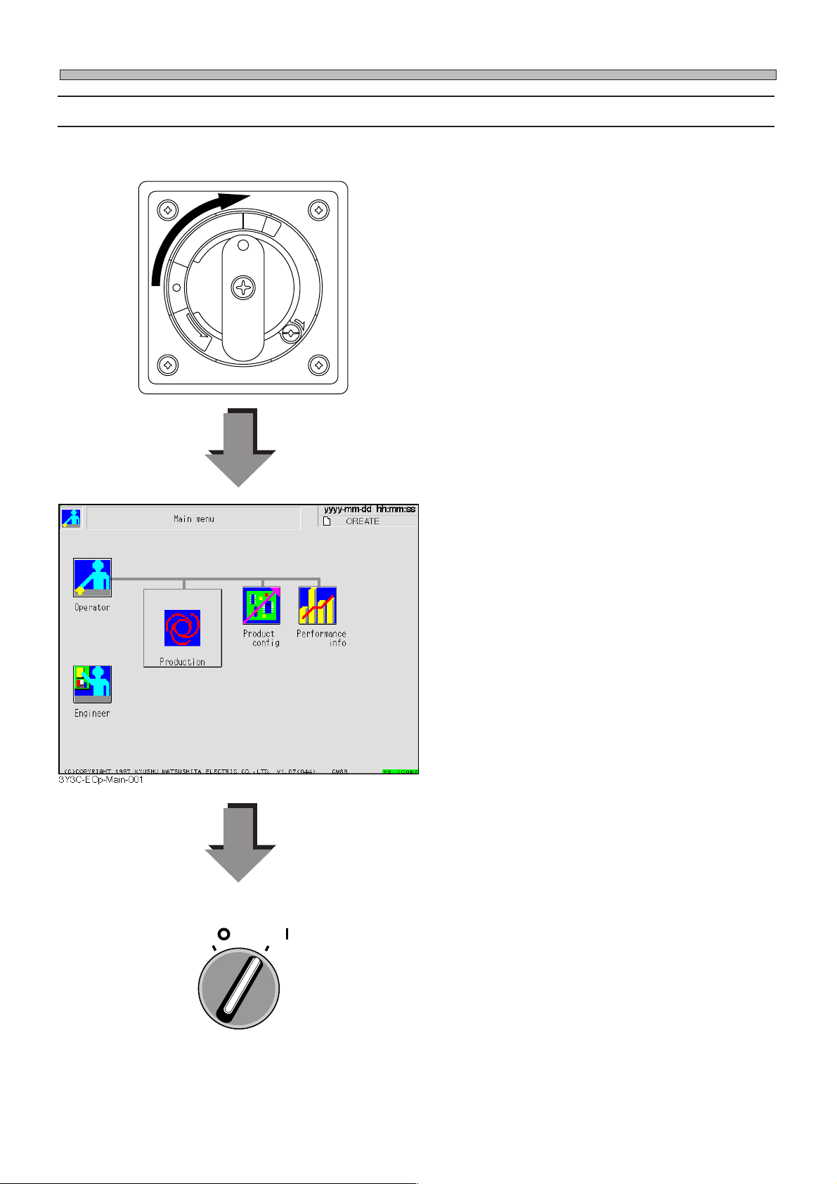
3-1-3 Starting up Machine
Start up machine in the following order.
O
P
I
R
T
F
F
O
T
E
S
E
R
N
E
S
A
E
L
E
R
1. Turn ON power supply switch.
• Power is supplied to machine and touch panel
starts to be displayed.
• Loading the system of machine starts. It takes
several minutes to load.
• After completion of loading the system, screen
as shown left is displayed.
Page 3-4
SERVO
OFF ( )
ON ( )
2. Turn ON servo switch on operating
panel.
193C-E-OMA03-A01-00
Page 51
3-2 Starting Production
NOTICE
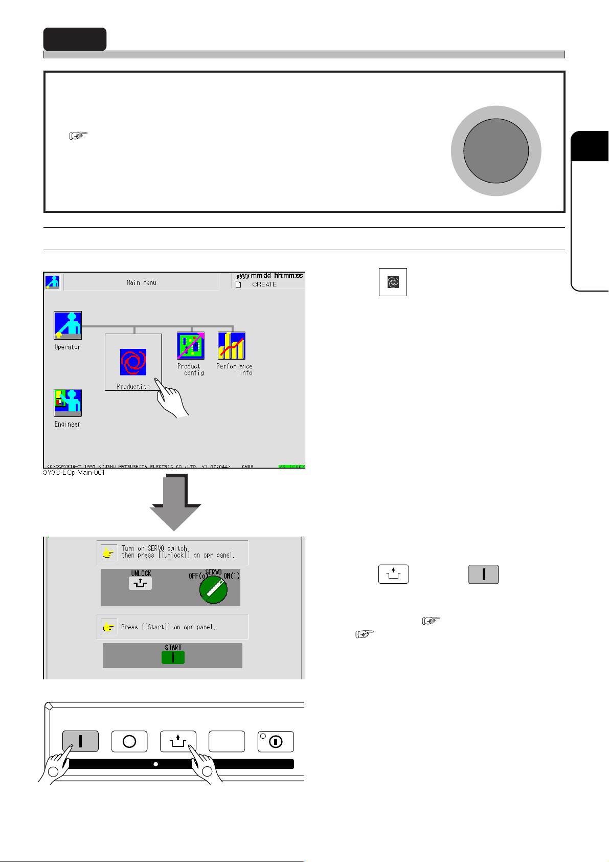
Before starting production, check the positions of emergency button and its operation method
( SAFETY PRECAUTIONS).
• When machine is in abnormal condition, press this button
immediately.
• Emergency stop buttons can be reset by being pulled
forward.
3-2-1 Starting Operation
1. Press
Production
E
M
E
S
on menu tree.
R
G
E
N
C
Y
3
DAILY PRODUCTION
P
T
O
3Y3C-EOp-Main-002
STAR T
2
193C-E-OMA03-A01-00
STOP
UNLOCK
KEY LOCK
STEP SELECT
1
2. After checking servo switch is ON,
UNLOCK
press
and then
ing panel within 2 seconds.
•Self diagnosis ( 3-2-2) → return to origin
( 3-2-3) are carried out. After that, when
board is transported in from previous process,
production starts.
START
on operat-
Page 3-5
Page 52
Starting Production
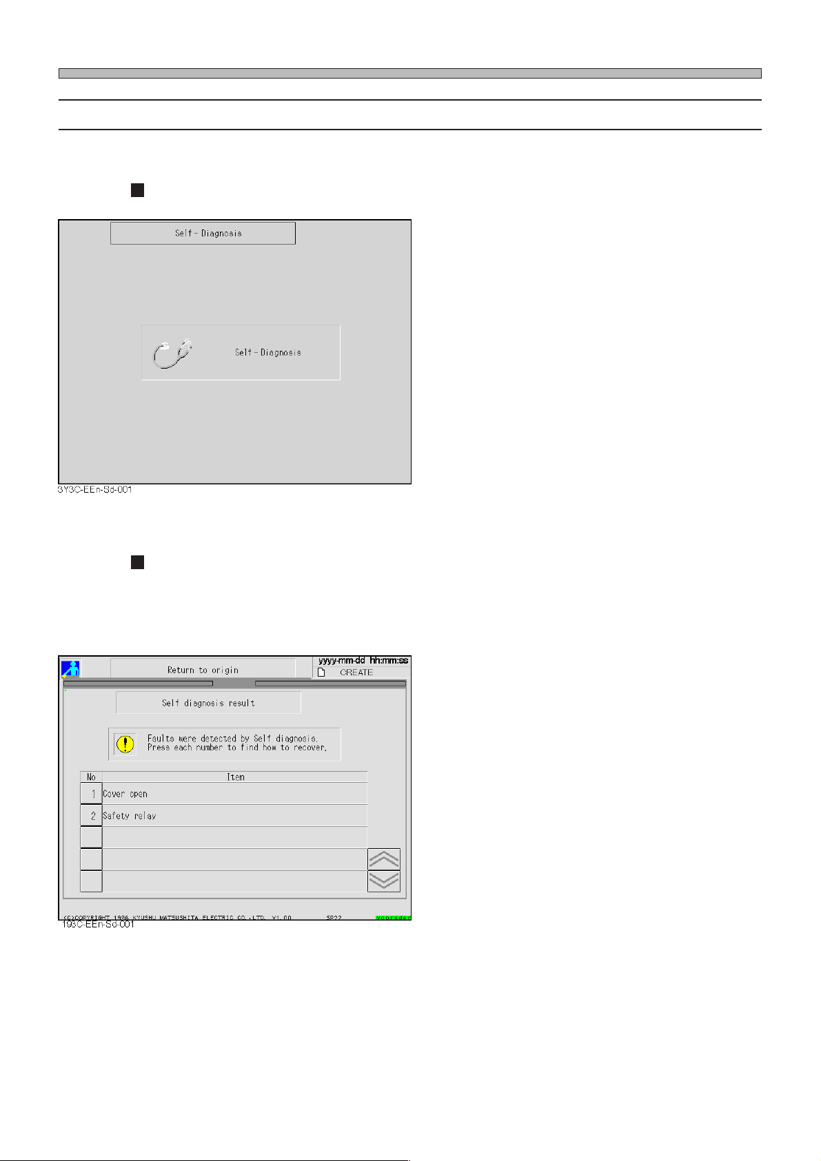
3-2-2 Self Diagnosis
Self-Diagnosis screen is displayed for an instant.
Machine’s condition is automatically checked.
• When machine’s condition is normal, “Return to
origin” is carried out.
<E.g.>
If any trouble is detected during self diagnosis, the following
screen appears.
• If any trouble is detected, “trouble item” is
displayed.
∗ See “Chapter 7 TROUBLESHOOTING” to solve
the trouble.
Page 3-6
193C-E-OMA03-A01-00
Page 53
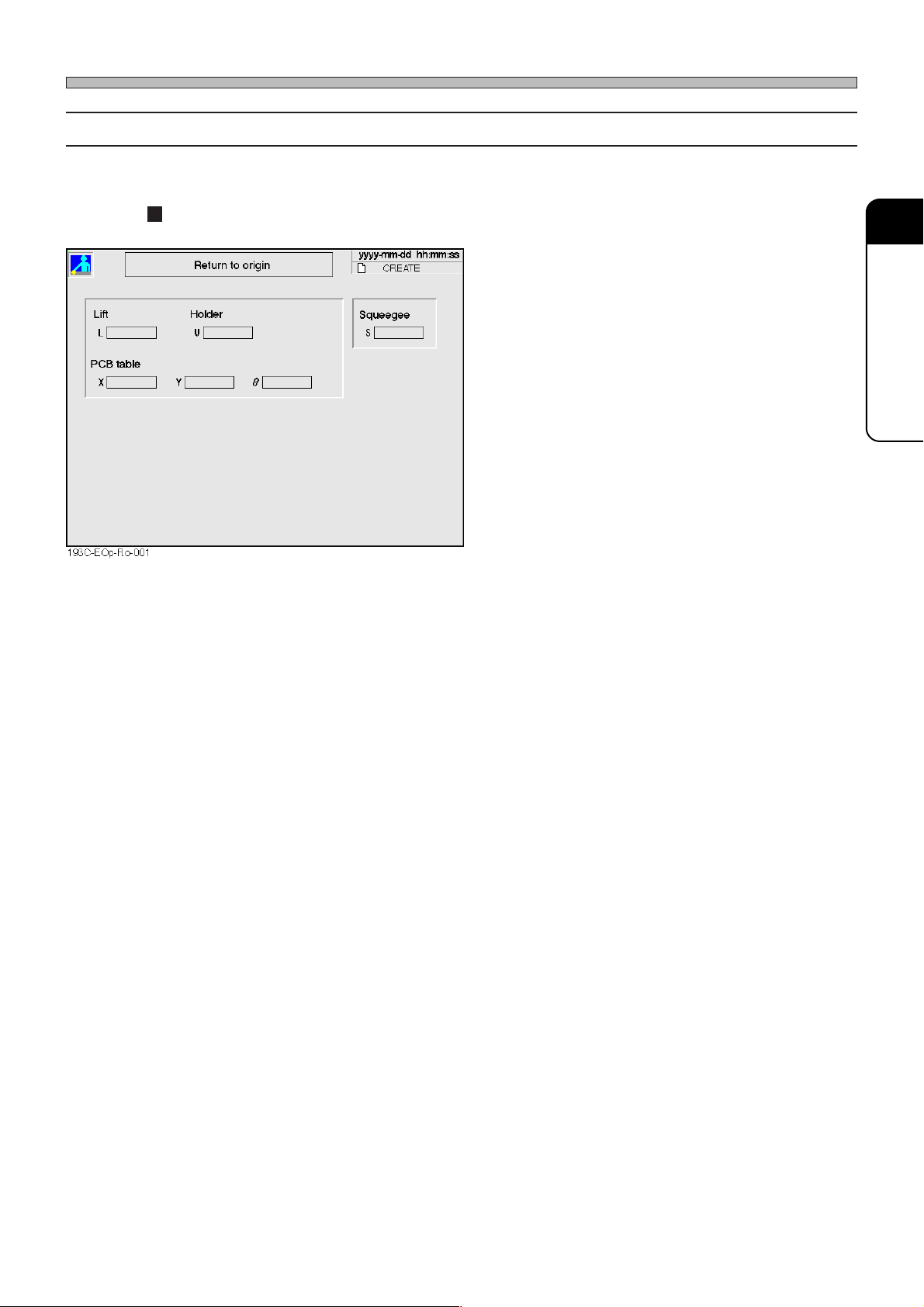
3-2-3 Return to Origin
Before mounting, each axis returns to the origin.
Starting Production
All the axes return to the origin.
• “Complete” is displayed for the axes returned to
the origin.
3
DAILY PRODUCTION
193C-E-OMA03-A01-00
Page 3-7
Page 54
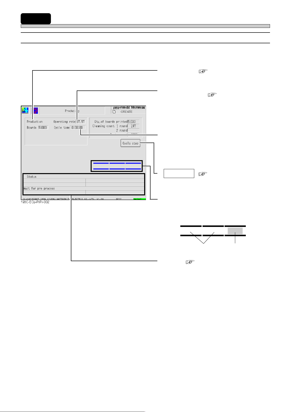
3-3 During Production
3-3-1 Information and Functions during Production
Basic production information and state of operation are displayed.
• Production ( 5-1 Run Information)
The number of produced boards.
• Operating rate ( 5-1 Run Information)
Operating rate of machine
• Cycle time
The time from when board is transported in
from left conveyor until when the clamp is off
after printing is completed.
• Cycle stop ( 3-4-1 Stop Operation)
This is used to stop production temporarily
after printing of the board being printed.
• Presence of board
The presence of board on conveyor is displayed.
E.g.)
No board Board
• Status ( 7-2 Check and Solutions)
Present state of machine is displayed.
Page 3-8
193C-E-OMA03-A01-03
Page 55
3-4 Production Stop
WARNING
DO NOT PLACE YOUR HANDS OR BODY INSIDE ACTIVE PART OF THE MACHINE WHEN IT IS IN A SINGLE STOP OR CYCLE STOP CONDITION.
The machine has been stopped only temporarily. You may be injured if the sensors are
actuated and the machine moves unexpectedly.
Turn OFF the servo switch before placing your hands or body inside the active part.
M34EB
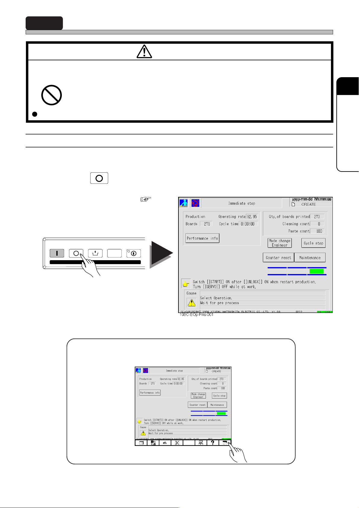
3-4-1 Stop Operation
a) Immediate stop (This is used to stop production immediately.)
STOP
1 Press
Production is stopped immediately.
(How to restart production 3-4-3)
START
STOP
UNLOCK
KEY LOCK
on operating panel.
STEP SELECT
3
DAILY PRODUCTION
193C-E-OMA03-A01-01
<How to stop production (return the screen to main menu)>
• When you press return key, the screen returns to main menu.
193C-EOp-Prls-001
Page 3-9
Page 56
Production Stop
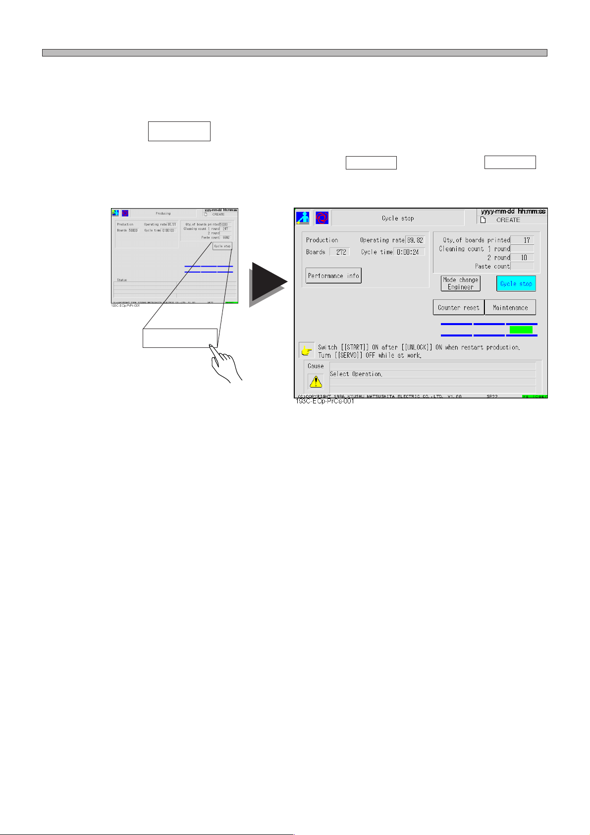
b) Cycle stop (This is used to stop production after printing of the
current board.)
1 Press Cycle stop on touch panel.
After printing of the current board is completed, production stops.
If you cancel cycle stop in the middle of printing (with Cycle stop highlighted), press Cycle stop
again. Then the display returns to usual screen, and production continues.
Cycle stop
To stop production, see “a) Immediate stop, <How to stop production (return the screen to main
menu)>” on the preceding page.
Page 3-10
193C-E-OMA03-A01-01
Page 57
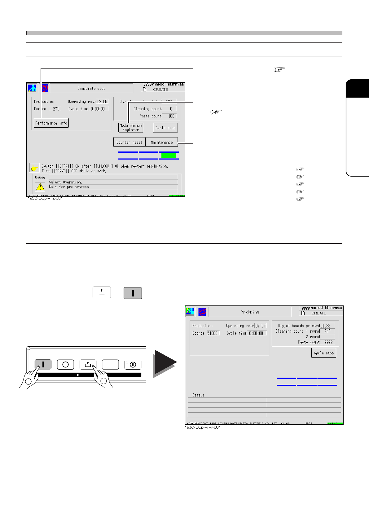
3-4-2 Information and Functions during Stop
a) Performance info ( Chapter 5)
You can check detailed information about
production.
b) Mode change
( Operating manual for engineers)
When you input the password, you can change
the current mode to engineer mode.
c) Maintenance
Maintenance during production can be carried
out.
a) Squeegee open/close ( 4-1)
b) Cleaning 1 round ( 4-3)
c) Cleaning 2 round ( 4-3)
d) Send out air of solvent ( 4-3)
e) Escape XY -table ( 4-3)
∗ b) and c) can be carried out only during a
cycle stop.
Production Stop
3
DAILY PRODUCTION
3-4-3 Restarting Production
Production restarts from immediate stop or cycle stop.
UNLOCK
1 Press
Production restarts.
START
2
STOP
UNLOCK
KEY LOCK
STEP SELECT
1
→
START
.
193C-E-OMA03-A01-01
Page 3-11
Page 58
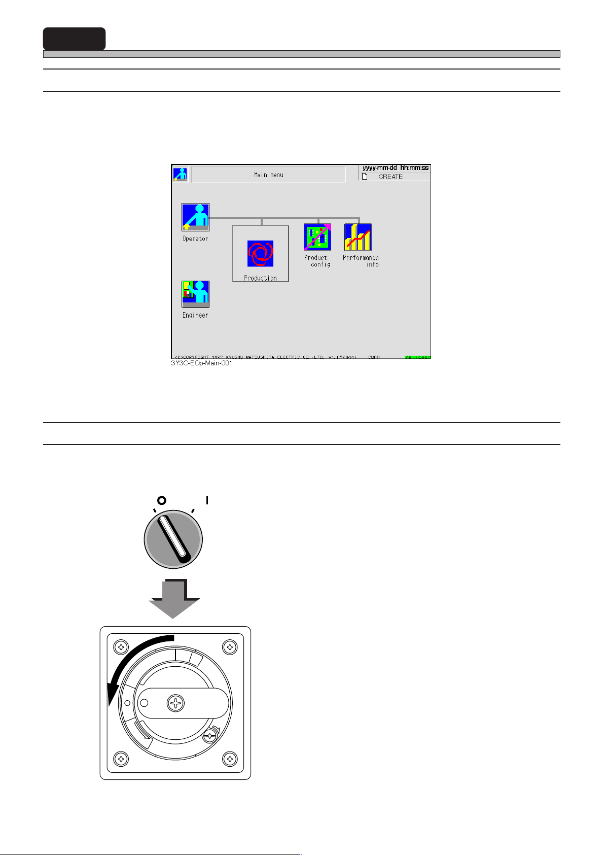
3-5 Completion of Production
3-5-1 Automatic Stop
When front stocker sends out the last board in the set number of production board, the stocker
transmits production end signal to next process (E.g. adhesive dispenser, etc.). When this machine
gets the signal, the machine automatically become a state of completion of production after producing the last board, and the display returns to main menu screen.
3-5-2 Finishing Machine
When the display returns to main menu screen, turn off power supply of machine in the following
order.
SERVO
OFF ( )
P
I
R
T
F
F
O
T
E
S
E
R
ON ( )
O
N
E
S
A
E
L
E
R
1. Turn OFF servo switch on operating
panel.
2. T urn OFF power supply switch.
Page 3-12
193C-E-OMA03-A01-01
Page 59
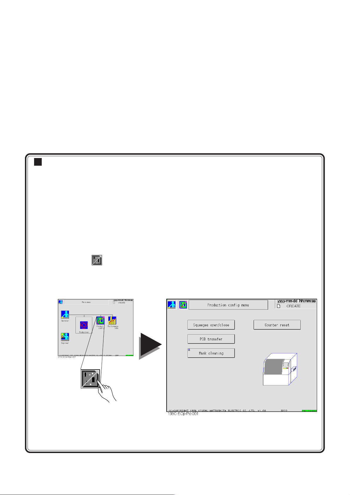
Chapter 4
PRODUCTION SETTINGS
PRODUCTION SETTINGS
Production settings
• Production settings is the mode for requisite settings for production, and for motion
check.
• This chapter describes the following items.
Squeegee open/close -- This is used to open and close squeegee.
PCB transfer--------------You can check board transport between conveyors, and between ma-
chines.
Mask cleaning------------ This is used to clean mask.
Counter reset------------- Cleaning count and paste count (the number of times of solder feed) can
be reset.
• You can operate to enter production settings from main menu.
Start the first operation for each item from here.
Press
Then “Production config menu” screen appears. After that, operate according to each item.
Product
config
on “Main menu” screen.
Product
config
193C-E-OMA04-A01-00
Page 4-1
Page 60
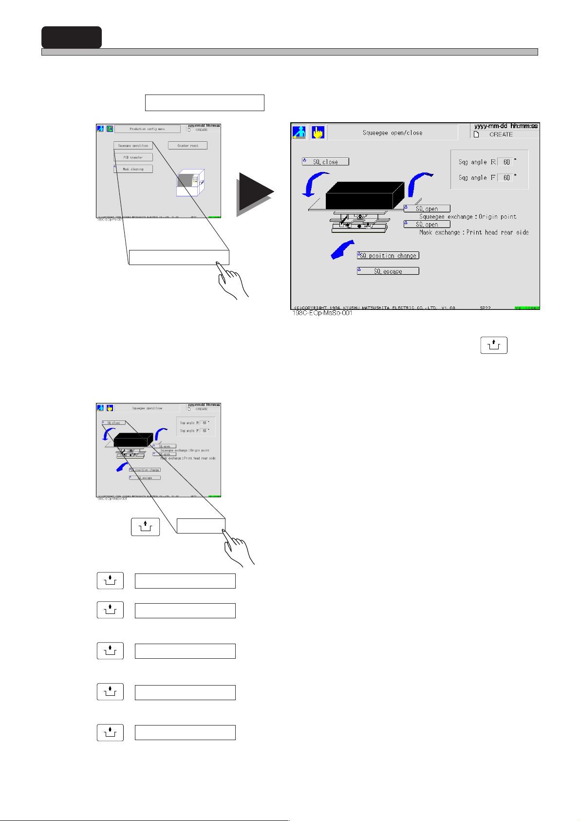
4-1 Squeegee Open/Close
This is used to open and close squeegee.
1 Press Squeegee open/close in Production config menu.
Squeegee open/close
2 Press a button of the command you want to execute while holding
on operating panel.
If power is not on, squeegee axis does not move, but only the squeegee open/close function is
carried out.
UNLOCK
E.g.)
UNLOCK
+ SQ. close ----- Opened squeegee is closed.
UNLOCK
+ SQ. open -----Squeegee is opened at the front side.
Squeegee exchange : Origin point
UNLOCK
+ SQ. open -----Squeegee is opened at the rear side.
Mask exchange : Print head rear side
UNLOCK
+ SQ. position change -----Squeegee moves to the position opposite to the current position.
UNLOCK
+ SQ. escape -----Squeegee moves to the position opposite to the current position.
+ SQ. close
This is used to change squeegees.
This is used to change masks.
The information of the current position of squeegee is lost.
The information of the current position of squeegee is saved.
UNLOCK
Page 4-2
193C-E-OMA04-A01-01
Page 61
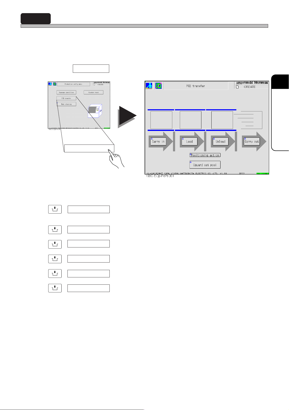
4-2 Board Transport
You can carry out from transporting board in to left conveyor until transporting it out to the next
process for each conveyor.
Board on the conveyor is displayed in green, board that is being transported is displayed with
blinking.
1 Press PCB transfer in Production config menu.
PCB transfer
4
PRODUCTION SETTINGS
UNLOCK
+ Carry in ---- Board is transported from the previous process to left conveyor.
Demand signal is transmitted to the previous process.
UNLOCK
+ Load ---- Board is transported from left conveyor to printing stage.
UNLOCK
+ Unload ----Board is transported from printing stage to right conveyor.
UNLOCK
+ Carry out ----Board is transported from right conveyor to the next process.
UNLOCK
+ Positioning action ---- Only the positioning of board is carried out.
UNLOCK
+ Uguard set posi ----Printing stage is moved to the front side of machine.
This is used to set support block and support pin.
193C-E-OMA04-A01-00
Page 4-3
Page 62
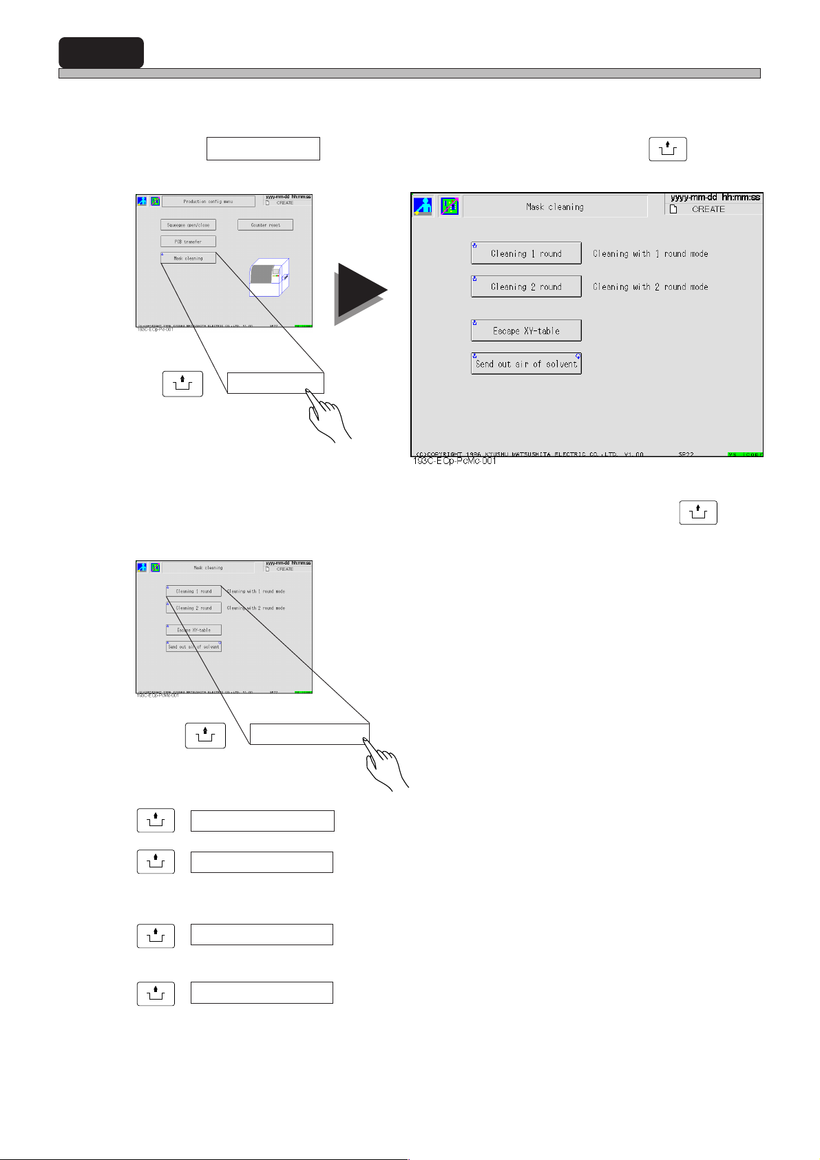
4-3 Mask Cleaning
This is used to clean mask.
1 Press Mask cleaning in Production config menu while holding
operating panel.
UNLOCK
+ Mask cleaning
UNLOCK
on
2 Press a button of the command you want to execute while holding
on operating panel.
UNLOCK
E.g.)
UNLOCK
+ Cleaning 1 round -----One-round cleaning is carried out.
UNLOCK
+ Cleaning 2 round -----Two-round cleaning is carried out.
UNLOCK
+ Escape XY-table -----X-Y table retracts to the inner side. This is used to clean the back
UNLOCK
+ Send out air of solvent ----- This is used to bleed cleaning solvent of air.
+ Cleaning 1 round
Wet cleaning is carried out in this mode.
But this can be used only when the data is set.
of mask by hand.
UNLOCK
Page 4-4
193C-E-OMA04-A01-01
Page 63
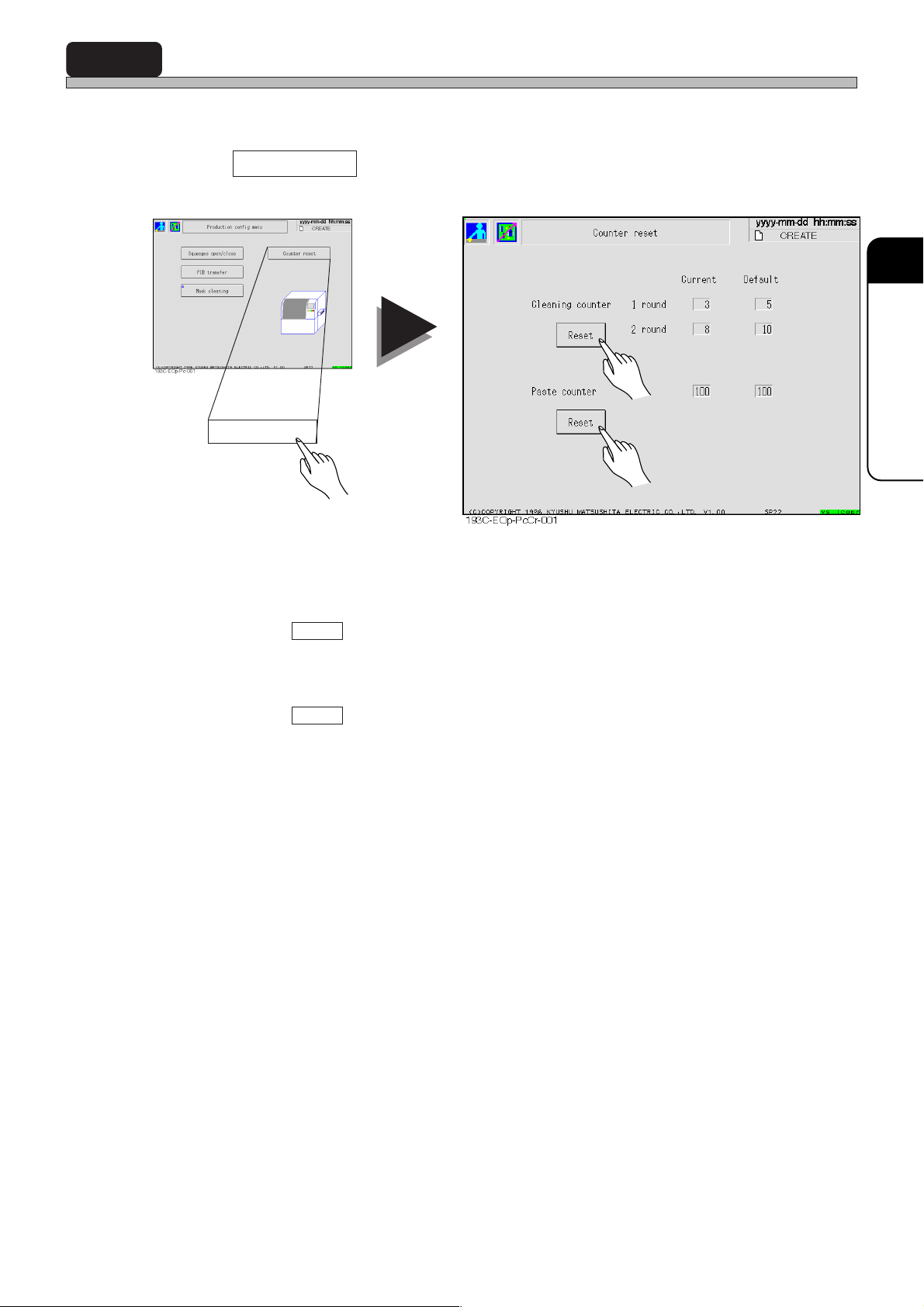
4-4 Counter Reset
Cleaning count and paste count (the number of times of solder feed) can be reset.
1 Press Counter reset in Production config menu.
Counter reset
4
PRODUCTION SETTINGS
a)
b)
a) How to reset cleaning count
When you press Reset , cleaning count is reset to the data set in cleaning data.
b) How to reset paste count
When you press Reset , paste count is reset to the data set in count data.
193C-E-OMA04-A01-00
Page 4-5
Page 64

= MEMO =
Page 4-6
193C-E-OMA04-A01-01
Page 65
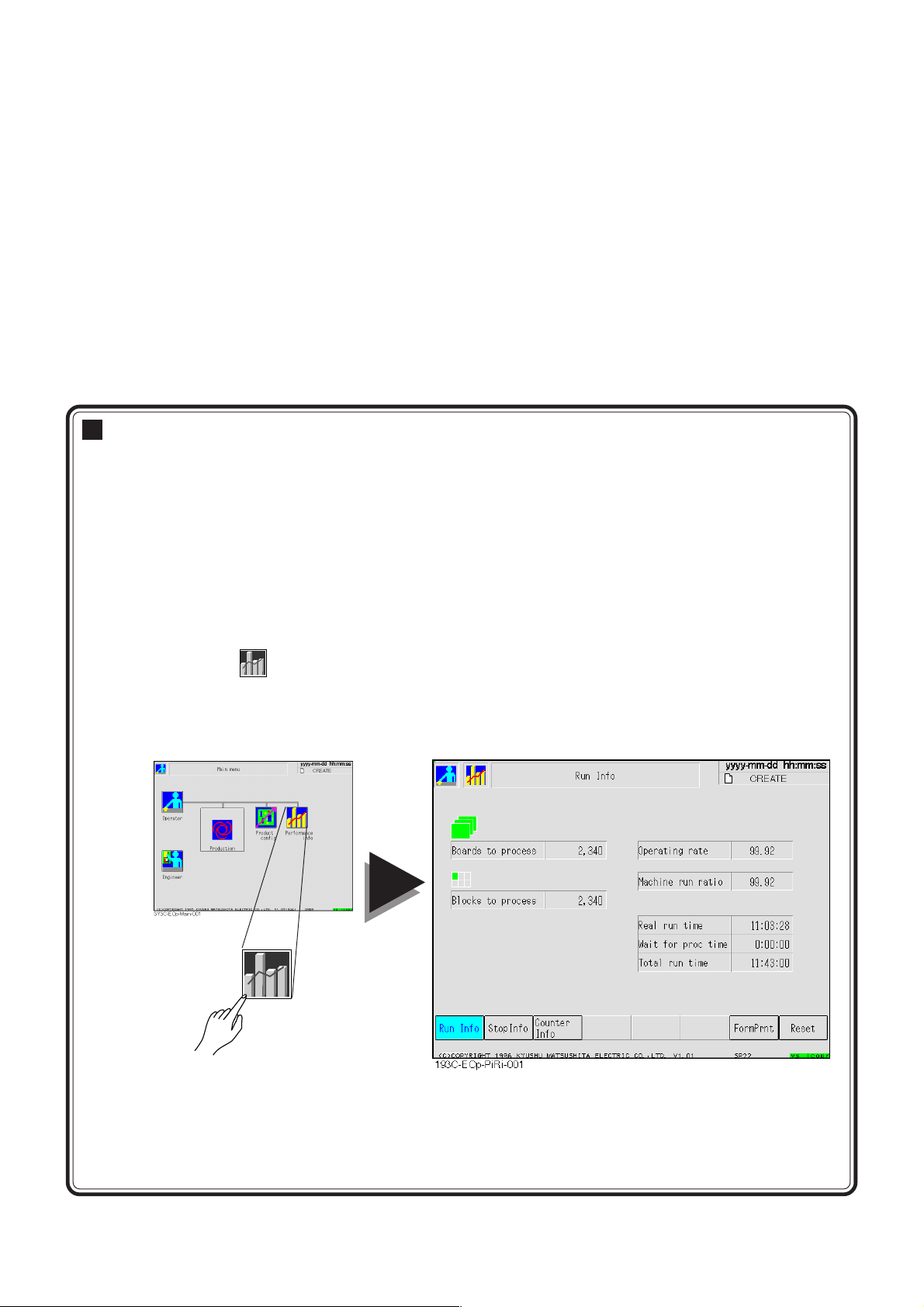
Chapter 5
PRODUCTION INFORMATION
PRODUCTION INFORMATION
Production information
• In production information, running condition of production boards is displayed.
• This chapter describes the following items.
Run Info ------- Run information of machine is displayed.
Stop Info------- Stop information during production is displayed for each item.
Counter Info -- The number of times of mask cleaning and solder feed are displayed.
Form Prnt ----- Production information is output to printer.
Reset----------- Production information can be reset.
• To enter production information,
Press
Then “Run Info” screen appears. After that, operate according to each item.
on “Main menu” screen.
Performance
info
Performance
info
193C-E-OMA05-A01-00
Page 5-1
Page 66
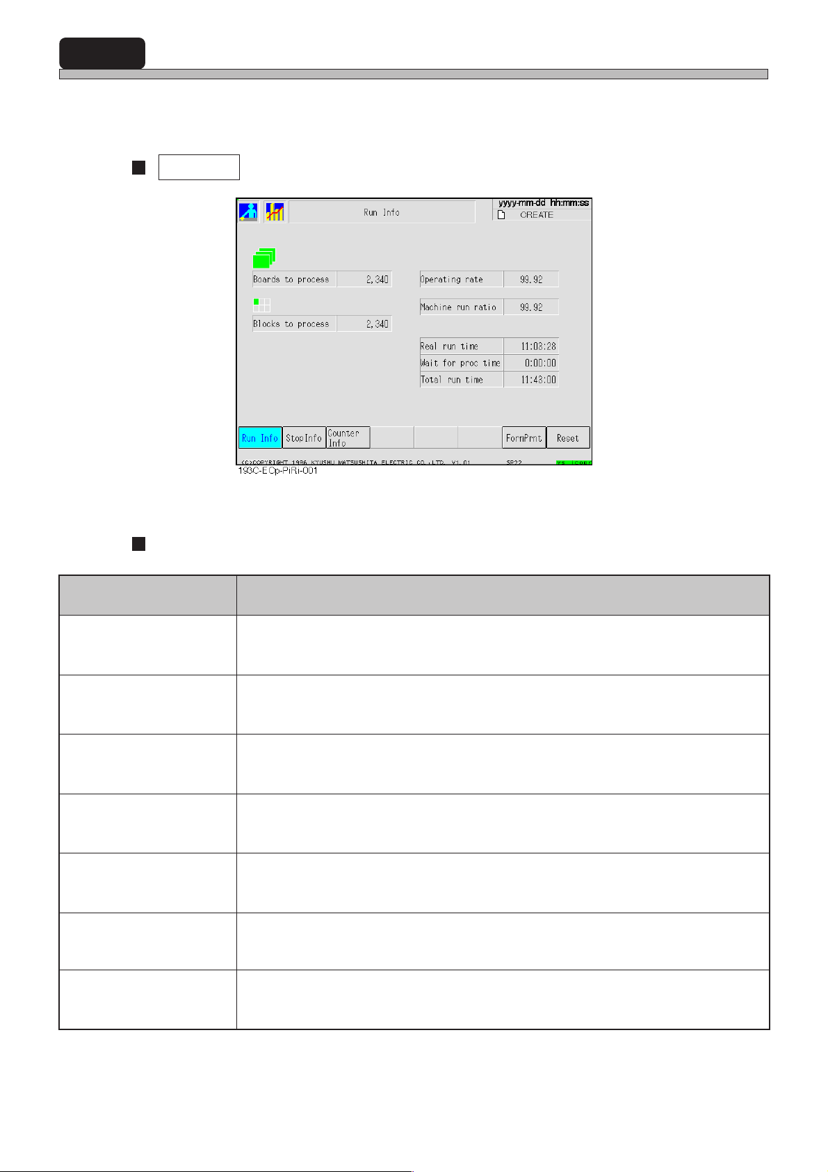
5-1 Run Information
Production quantity and running time, etc. of boards and blocks are displayed.
• Without reset, data will be added on irrespective of change of production board.
Run Info
Definitions of items
metI noitinifeD
ssecorpotsdraoB
]hguorht
ssecorpotskcolB skcolb)detnirp(decudorpyllautcaforebmunehT
etargnitarepO
oitarnurenihcaM
emitnurlaeR
emitcorproftiaW
.edom
]emitnurlatoT/emitnurlaeR[
]emitnwodlatoT-emitnurlatoT[
enihcamhguorhtdessapsdraobehtforebmunehT
dessaptsujsdraobdecudorptonforebmunehT+sdraobdecudorpforebmunehT[
noitcudorpgnirudnoitcudorprofgnikrowyllautcasienihcamnehwemitehtfoetaR
emitnurlaeRotemitcorproftiaWgniddaflestienihcamfoetargninnuR
]emitnurlatoT/)emitcorproftiaW+emitnurlaeR([
dnasuoiverproftiawdnasrorreoteudemitpotsgnitnuomdetcartbusemitehT
edomnoitcudorpgnirudemitehtmorf,.cte,sessecorptxen
deraperpebotsessecorptxendnasuoiverprofgnitiawemitehT
]emitgnitiawssecorptxen+emitgnitiawssecorpsuoiverP[
193C-020TE
Page 5-2
emitnurlatoTenihcamfoedomnoitcudorpgnirudemitehT
193C-E-OMA05-A01-00
Page 67
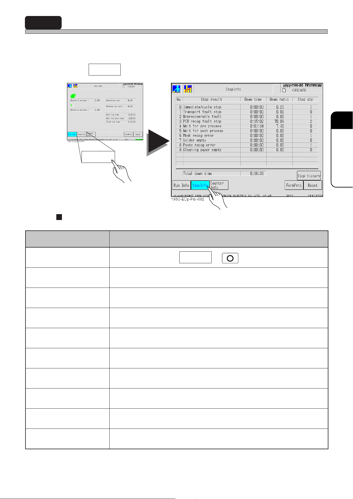
5-2 Stop Information
Stop information is displayed for each factor that made machine stop during production. You can
also see the details about the stop cases until now.
• Without reset, data will be added on irrespective of change of production board.
1 Press Stop Info .
Stop Info
5
5
PRODUCTION
INFORMATION
Meanings of items
emanelbuorT gninaeM
potselcyc/etaidemmIgnisserpoteudpotsehTpotSelcyCrorotarepoyb
potstluaftropsnarTrorretropsnartdraoboteudpotsehT
tluafelbarevocernoN .noitarepoeunitnoctonnacuoyhcihw,elbuortehtoteudpotsehT
potstluafgocerdraoBrorrenoitingocerdraoboteudpotsehT
ssecorp-tsop/-erproftiaW
rorregocerksaMrorrenoitingocerksamoteudpotsehT
ytpmeredloSredlosfokcaloteudpotsehT
STOP
txenotrossecorpsuoiverpmorftropsnartdraobroftiawoteudpotsehT
ssecorp
emitnwodlatoTsemitpotsdenoitnem-evobafolatoT
193C-021TE
193C-E-OMA05-A01-02
rorregoceretsaProrrenoitingocerredlosoteudpotsehT
ytpmerepapgninaelCrepapgninaelcfokcaloteudpotsehT
Page 5-3
Page 68
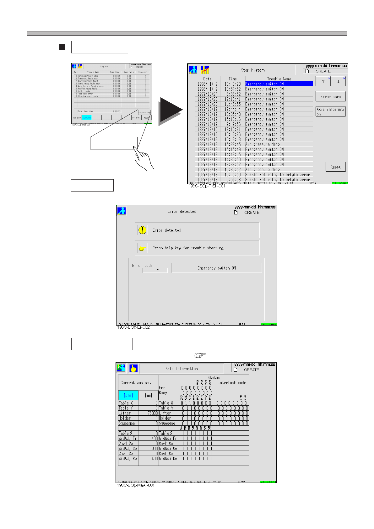
Stop Information
Stop history
Stop history during automatic operation is displayed. (Max. 20 cases can be saved.)
a) Error scrn
The screen an error occurred at is displayed.
Stop history
Page 5-4
b) Axis information
The axis information that an error occurred ( Operating manual for engineers 7-7)
193C-E-OMA05-A01-00
Page 69
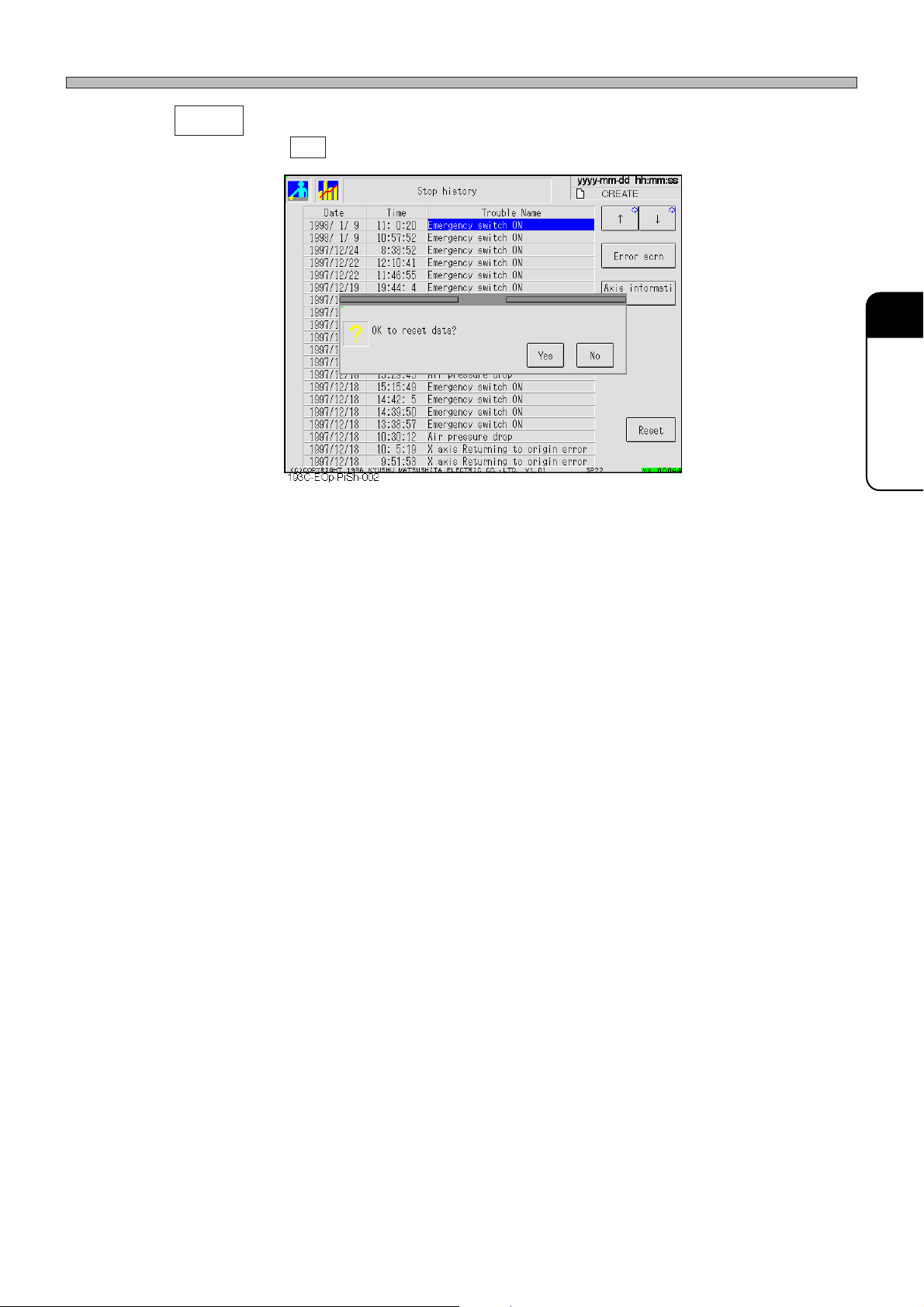
c) Reset
When you press Yes , stop history is reset.
Stop Information
5
5
PRODUCTION
INFORMA TION
193C-E-OMA05-A01-00
Page 5-5
Page 70
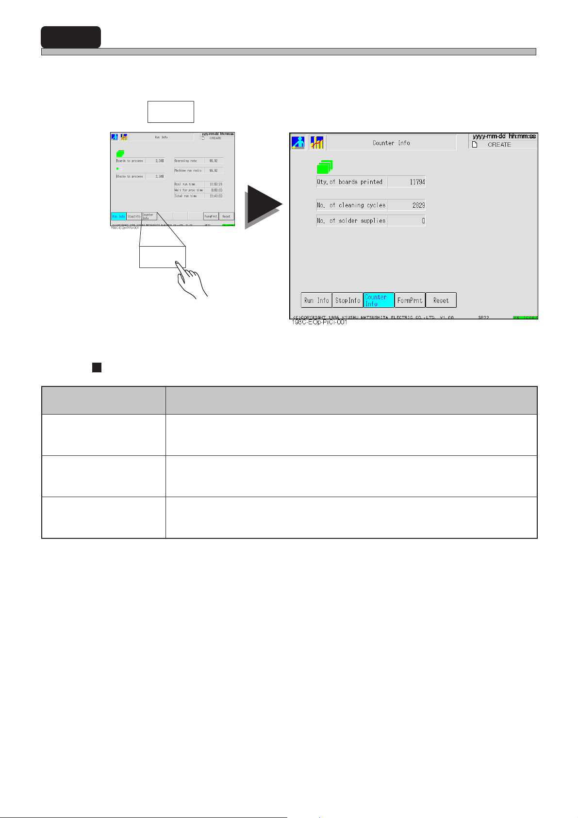
5-3 Counter Information
The number of times of mask cleaning and solder feed are displayed.
• “No. of solder supplies” is displayed only when the automatic solder feed unit (option) is installed.
1 Press .
Counter
Info
Counter
Info
Definitions of items
193C-022TE
metI noitinifeD
detnirpsdraobfo.ytQsdraobdetnirpforebmunehT
selcycgninaelcfo.oNgninaelcksamfosemitforebmunehT
seilppusredlosfo.oNdeefredlosfosemitforebmunehT
Page 5-6
193C-E-OMA05-A01-00
Page 71
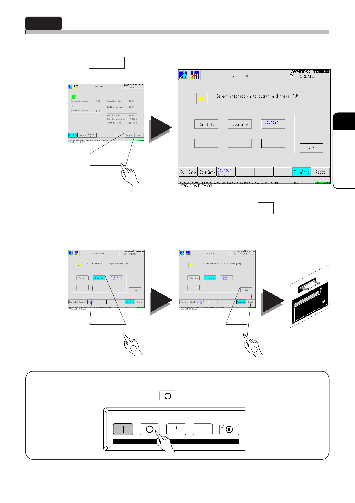
5-4 Form Printing
Production information is output to printer.
1 Press Form Prnt .
Form Prnt
5
5
PRODUCTION
INFORMA TION
2 Choose a switch of information to be output, and press Run .
Information switches are highlighted by being pressed and reset by being pressed again. It is
possible to choose more than a piece of information at a time.
E.g.)
1
• Press
<How to stop>
STOP
to stop output.
RunStop Info
2
Printout
193C-E-OMA05-A01-00
STAR T
STOP
UNLOCK
KEY LOCK
STEP SELECT
Page 5-7
Page 72
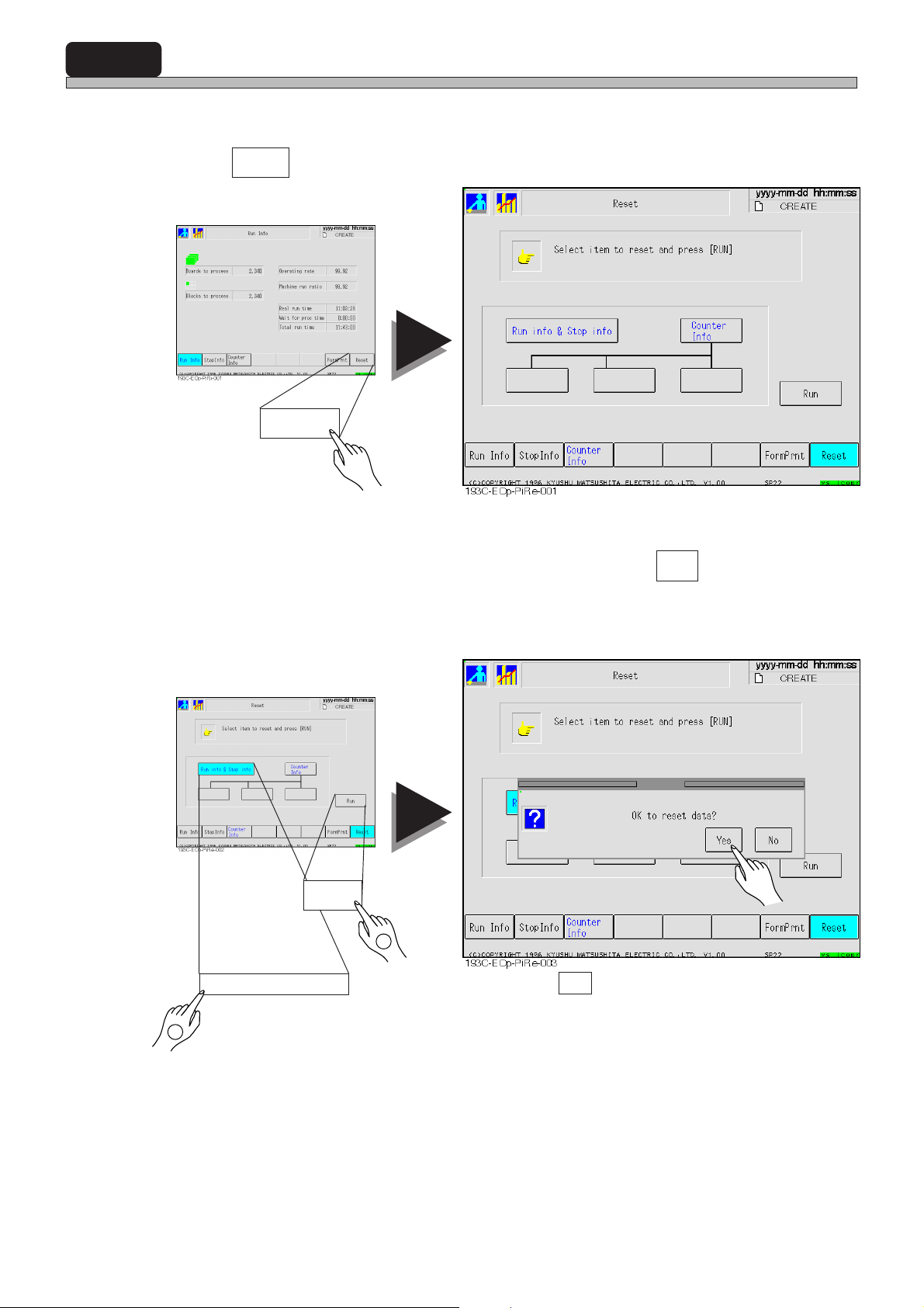
5-5 Reset
Production information can be reset.
1 Press Reset .
Reset
2 Choose a switch of information to be reset, and press Run .
Information switches are highlighted by being pressed and reset by being pressed again. It is
possible to choose more than a piece of information at a time.
Run
2
E.g.) Run info & Stop info
Press Yes to reset chosen information.
Page 5-8
1
193C-E-OMA05-A01-00
Page 73
Chapter 6
SETTING PRODUCTION
SETTING PRODUCTION
MATERIALS
MATERIALS
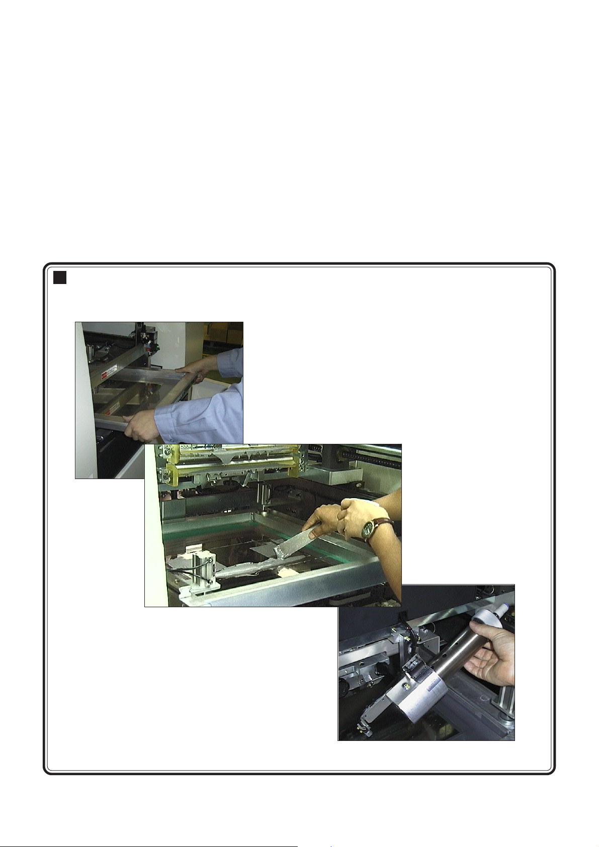
Supplying production materials
This chapter describes how to set mask and how to supply production materials.
193C-037P
193C-041P
193C-E-OMA06-A01-00
Page 6-1
Page 74
6-1 Setting Mask
This section describes how to set mask.
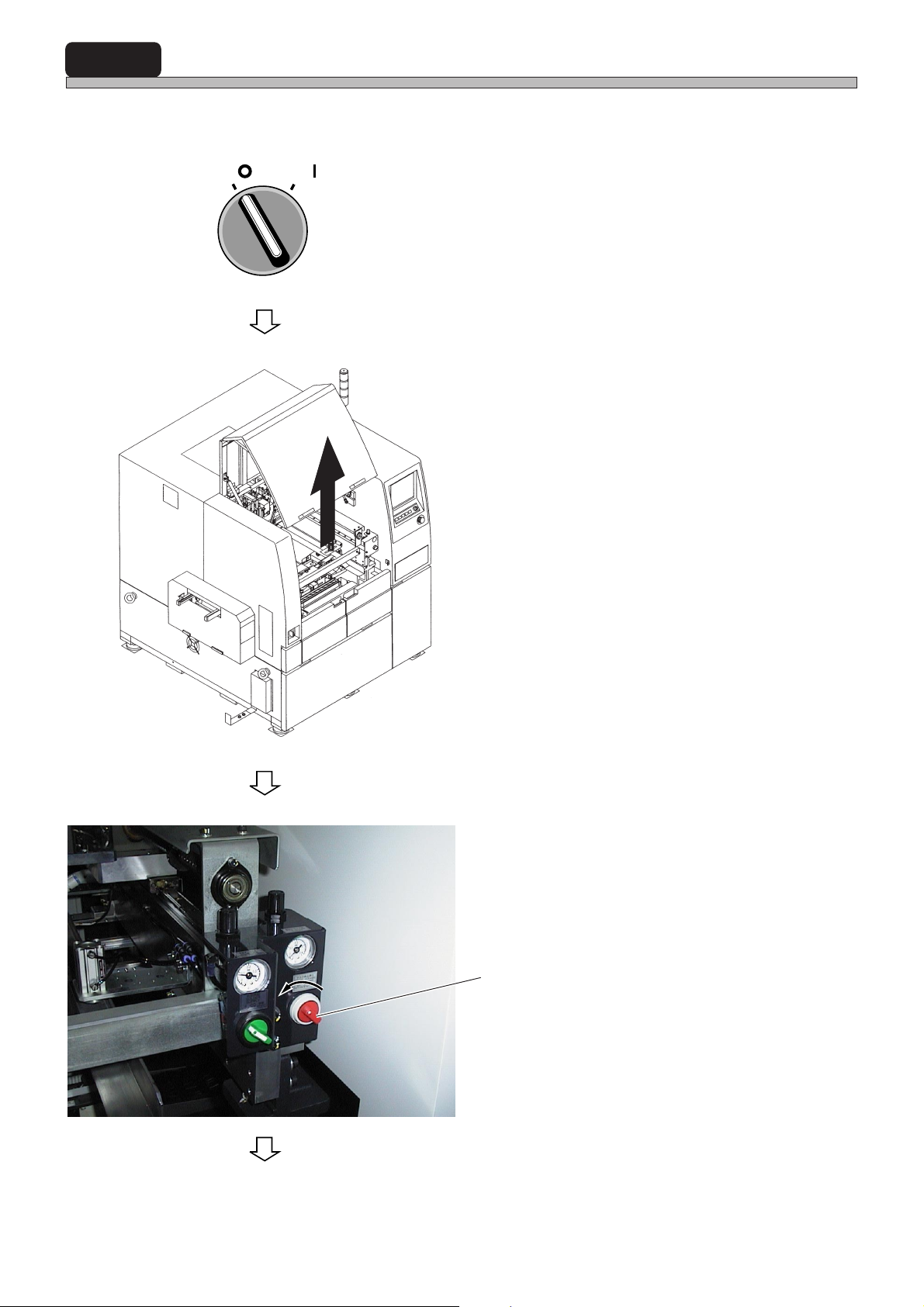
SERVO
OFF ( )
ON ( )
1. Turn OFF the servo switch on operat-
ing panel.
2. Open the front safety cover.
193C-038P
193C-AC02
3. Rotate the mechanical valve for mask
frame holder counterclockwise.
Mechanical valve for mask frame holder
Page 6-2
To the next page
193C-E-OMA06-A01-00
Page 75
Setting Mask
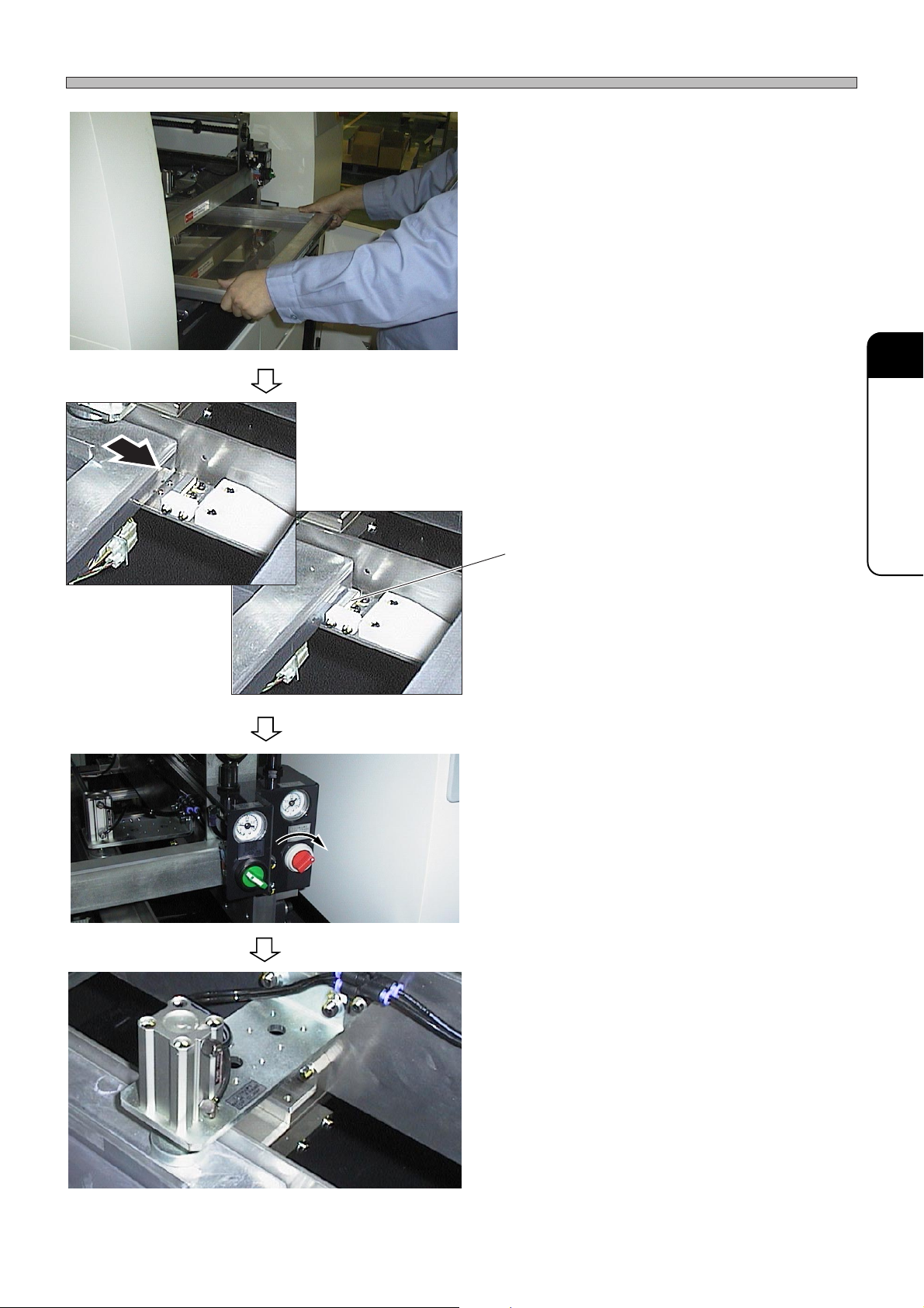
4. Check the direction, then insert mask.
∗ Be careful not to damage the lower side of
mask.
193C-037P
193C-032P
193C-033P
5. Draw the mask until it touches a
stopper at the right front side.
Stopper
6. Rotate the mechanical valve for mask
frame holder clockwise.
6
SETTING PRODUCTION
MATERIALS
193C-039P
193C-040P
193C-E-OMA06-A01-00
• The mask is fixed.
7. Make sure the mask is fixed firmly.
Page 6-3
Page 76
6-2 Supplying Solder
When you start production, check the printing direction of squeegee, then put the solder whose
quantity is specified by engineer onto mask by using spatula, etc.
∗ If solder is left as it is for hours, it dries up and becomes unavailable. So, supply solder just before
starting production.
The method of supplying solder during production varies depending on ON/OFF setting of
“AutoSolderSupply” of function switch and “whether or not the automatic solder feed unit (option) is
installed.”
This section describes how to supply solder during production.
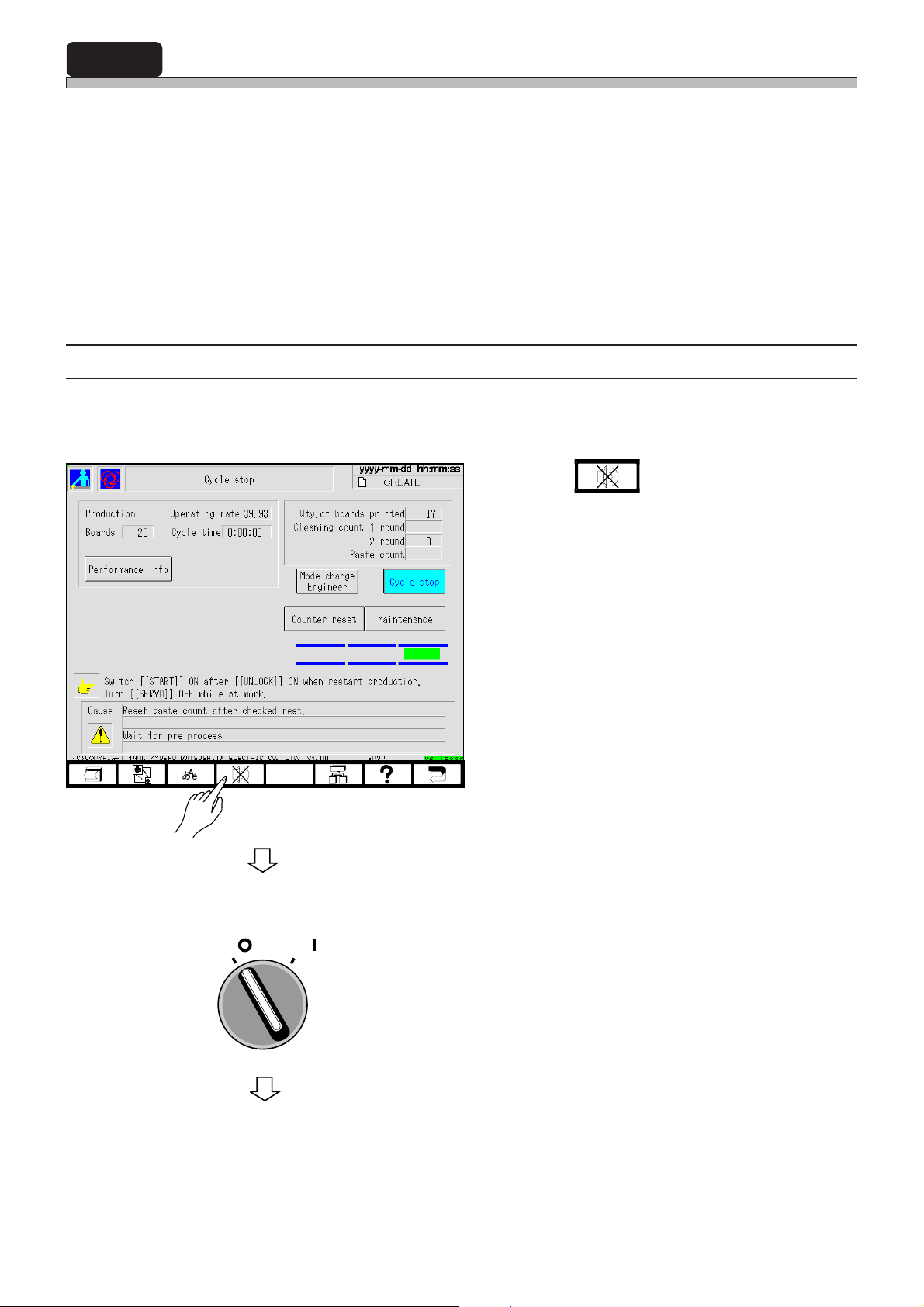
6-2-1 Case that “AutoSolderSupply” Is OFF
When “Paste count” is “0”, machine comes to a cycle stop with a buzzer. Supply solder in the
following procedures.
1. Press .
193C-EOp-PrCs-002
SERVO
OFF ( )
ON ( )
• The buzzer stops.
2. Turn OFF the servo switch on operat-
ing panel.
Page 6-4
To the next page
193C-E-OMA06-A01-01
Page 77
193C-AC02
Supplying Solder
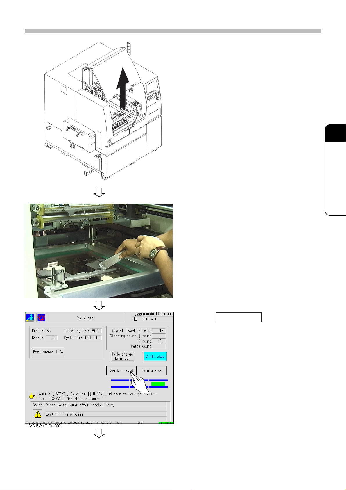
3. Open the front safety cover.
6
SETTING PRODUCTION
MATERIALS
4. Check the remaining quantity of
solder . If the solder is a little, supply it
manually checking the printing direction.
5. Press Counter reset .
193C-E-OMA06-A01-01
To the next page
Page 6-5
Page 78
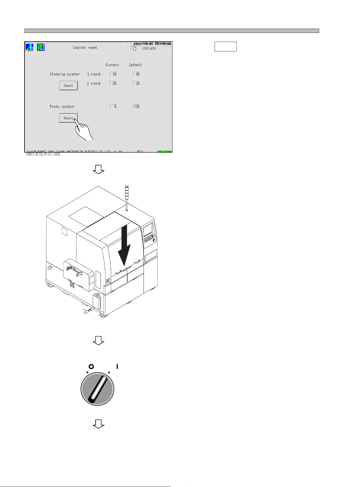
Supplying Solder
6. Press Reset .
• Paste count is reset.
193C-AA00
SERVO
OFF ( )
ON ( )
7. Close the front safety cover.
8. Turn ON the servo switch on operat-
ing panel.
Page 6-6
To the next page
193C-E-OMA06-A01-00
Page 79
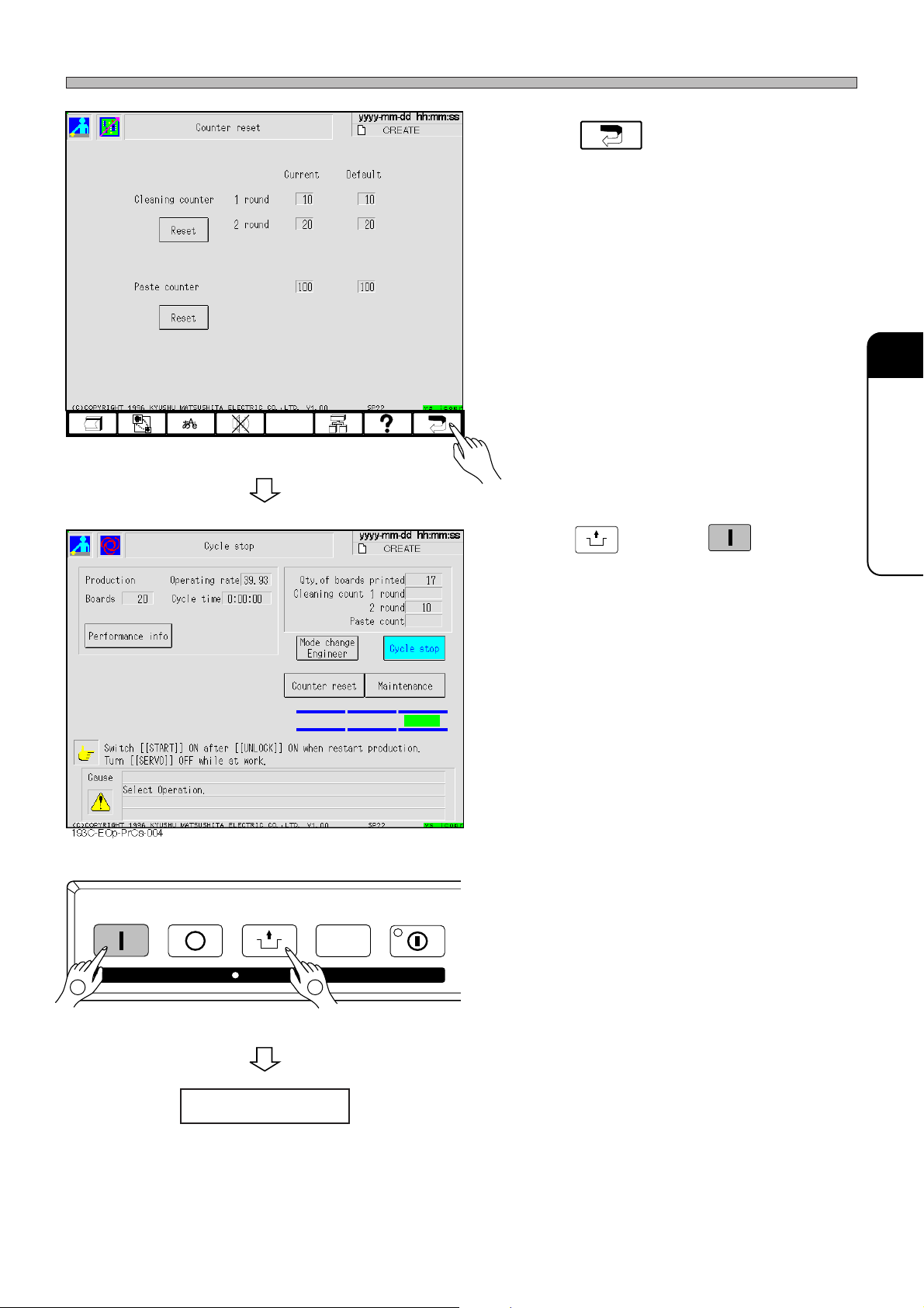
193C-EOp-PrCs-002
Supplying Solder
9. Press .
• The display returns to Cycle stop screen.
6
SETTING PRODUCTION
MATERIALS
STAR T
STOP
UNLOCK
STEP SELECT
UNLOCK
10. Press
and then
ing panel within 2 seconds.
START
on operat-
193C-E-OMA06-A01-01
KEY LOCK
Production resumes.
12
Page 6-7
Page 80
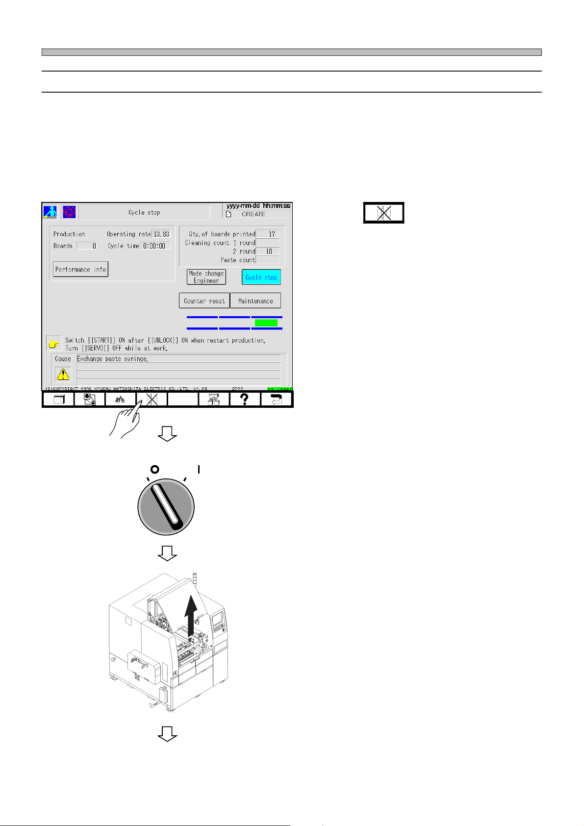
Supplying Solder
6-2-2 Case that “AutoSolderSupply” Is ON
When the automatic solder feed unit (option) is installed, turn ON “AutoSolderSupply” of function
switch.
When it is ON, the sensor of the holder of the automatic solder feed unit checks the quantity of
solder in syringe.
If the quantity of solder in syringe is decreased below the sense level of sensor, machine comes to
a cycle stop with a buzzer.
Supply solder in the following procedures.
1. Press .
• The buzzer stops.
193C-EOp-PrCs-003
SERVO
OFF ( )
ON ( )
2. Turn OFF the servo switch on operat-
ing panel.
3. Open the front safety cover.
Page 6-8
193C-AC02
To the next page
193C-E-OMA06-A01-01
Page 81
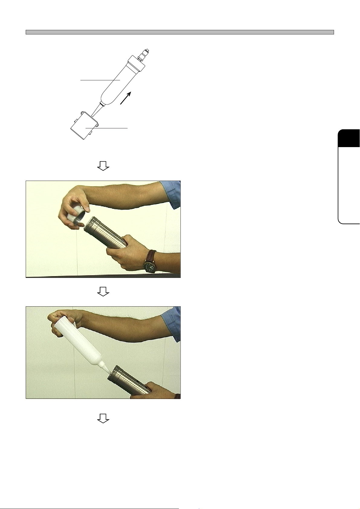
Syringe
Supplying Solder
4. Pull out syringe from holder.
Holder
153C-IL031
5. Remove the cap of the syringe.
6. Change cartridges.
6
SETTING PRODUCTION
MATERIALS
193C-E-OMA06-A01-00
* Remove the used cartridge from the syringe
and insert a new one.
To the next page
Page 6-9
Page 82
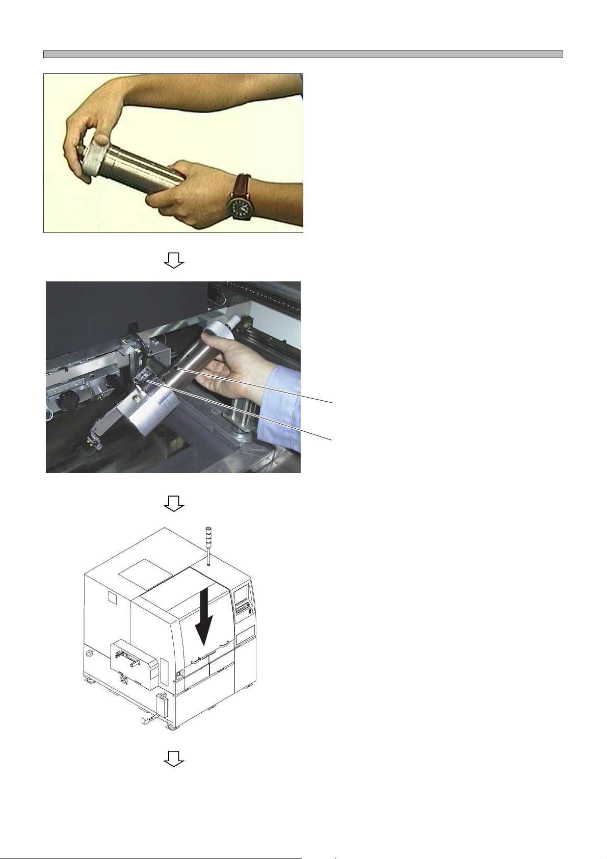
Supplying Solder
7. Fit the cap of the syringe.
8. Insert the syringe into the holder and
fit the tube.
∗ Insert it so that the hole will agree with the
position of sensor.
193C-034P
Hole
Sensor
9. Close the front safety cover.
193C-AA00
Page 6-10
To the next page
193C-E-OMA06-A01-00
Page 83
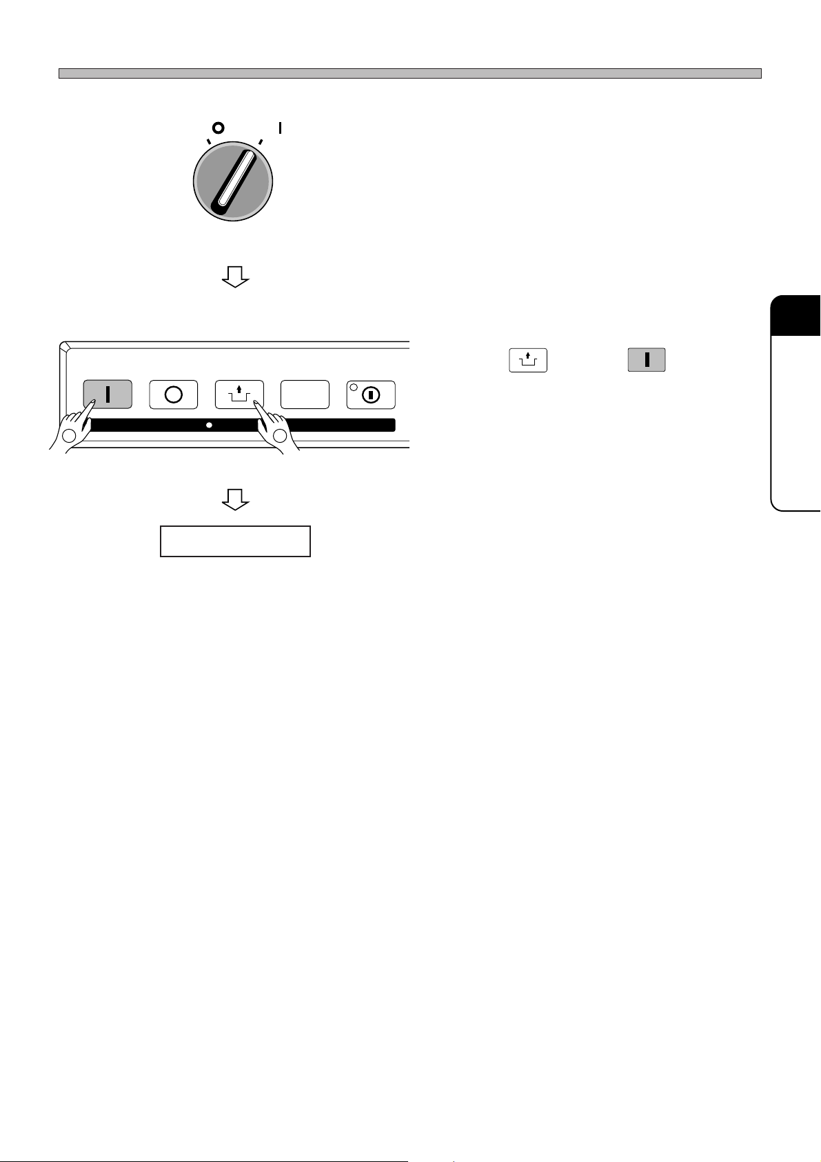
Supplying Solder
STAR T
OFF ( )
STOP
SERVO
ON ( )
UNLOCK
KEY LOCK
STEP SELECT
12
10. Turn ON the servo switch on operat-
ing panel.
UNLOCK
11. Press
and then
ing panel within 2 seconds.
START
on operat-
6
SETTING PRODUCTION
MATERIALS
Production resumes.
193C-E-OMA06-A01-00
Page 6-11
Page 84
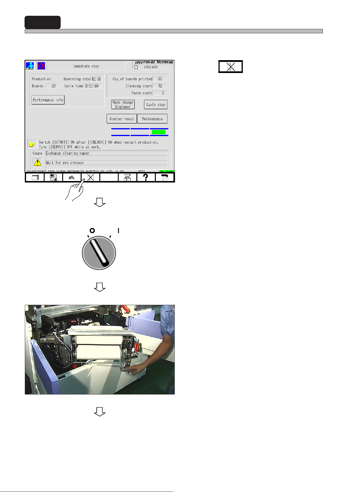
6-3 Supplying Cleaning Paper
If cleaning paper runs out, the following screen is displayed with a buzzer and machine comes to a
cycle stop.
193C-EOp-PrIs-002
1. Press .
• The buzzer stops.
SERVO
OFF ( )
ON ( )
2. Turn OFF the servo switch on operat-
ing panel.
3. Open the cover of cleaning area, then
draw out the cleaning unit.
Page 6-12
To the next page
193C-E-OMA06-A01-01
Page 85
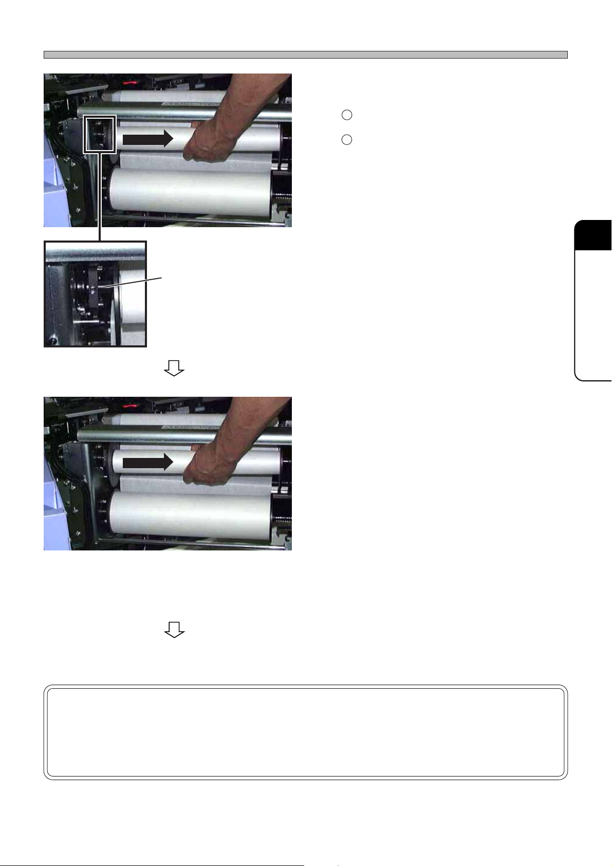
153C-006P
Move the paper tube untill it
separates from this projection.
Supplying Cleaning Paper
4. Remove the paper tubes of paper roll.
1 Move the paper tube of paper roll to the right.
2 After making sure the flange separates from
the projection at the left side, remove the paper
tube. (Remove both the paper tubes on the
take-up side and the supply side.)
∗ Do not dispose of the paper tube on the supply
side because it will be used as the paper tube
on the take-up side later.
6
SETTING PRODUCTION
MATERIALS
153C-007P
153C-006P
5. Fit the flanges to a new paper roll and
fit it on the supply side (lower side).
6. Fit the flanges to the paper tube re-
moved at the step 4) and fit it on the
take-up side (upper side).
7. Remove the cover of solvent nozzle
part.
∗ Remove the two screws, then remove the
cover.
To the next page
NOTICE
If the paper is not taken up properly because the paper tube fit to the flanges
on the take-up side races, stop using that paper tube and use the accompanying aluminum tube.
193C-E-OMA06-A01-01
Page 6-13
Page 86
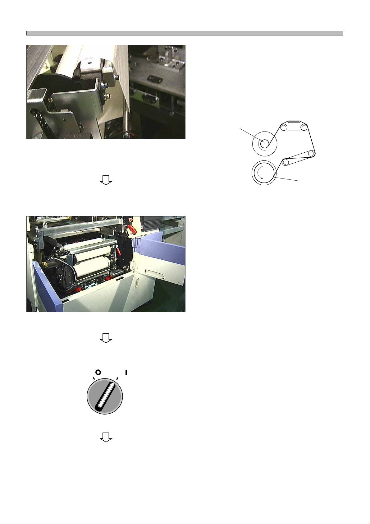
Supplying Cleaning Paper
8. Pass the paper as shown on the left,
then wind it around the take-up paper
tube two or three times.
• Before winding the paper, fix the tip of it to the
paper tube with a masking tape, etc. so that it
will not come off.
Paper tube
153C-IL012
New paper
9. Return the unit into the main body,
then close the cover of cleaning area.
Page 6-14
SERVO
OFF ( )
To the next page
ON ( )
10. Close the front and center safety
covers.
11. Turn ON the servo switch on operat-
ing panel.
193C-E-OMA06-A01-01
Page 87
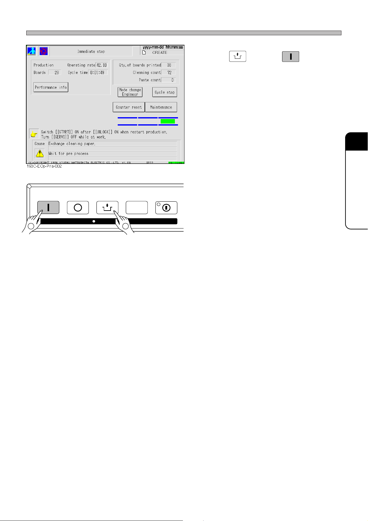
Supplying Cleaning Paper
STAR T
STOP
UNLOCK
KEY LOCK
STEP SELECT
12
12. Press
UNLOCK
and then
START
on operat-
ing panel within 2 seconds.
∗ If the paper runs out during cleaning, carry out
cleaning again, then resume production.
6
SETTING PRODUCTION
MATERIALS
193C-E-OMA06-A01-01
Page 6-15
Page 88
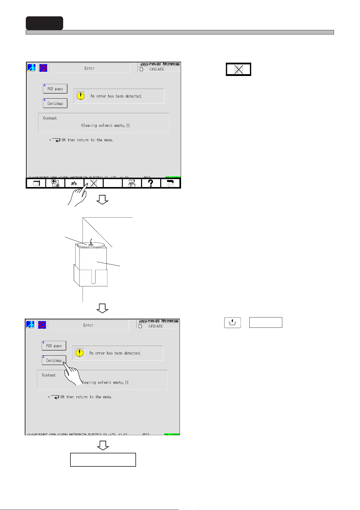
6-4 Supplying Cleaning Solvent
If cleaning solvent are running short, the following screen is displayed with a buzzer and machine
comes to a cycle stop.
1. Press .
• The buzzer stops.
Lid
Main body
Solvent tank
2. Open the lid of solvent tank, then
supply solvent.
•2 l of solvent can be contained.
∗ Use IPA or ethyl alcohol as the solvent.
(The mixture of IPA and ethyl alcohol is also
available.)
∗ Never use the solvent other than the above-
mentioned ones.
Otherwise, machine will be damaged.
UNLOCK
3. Press
• After the solvent is supplied, cleaning is
resumed.
+ Continue .
Page 6-16
Production resumes.
193C-E-OMA06-A01-01
Page 89
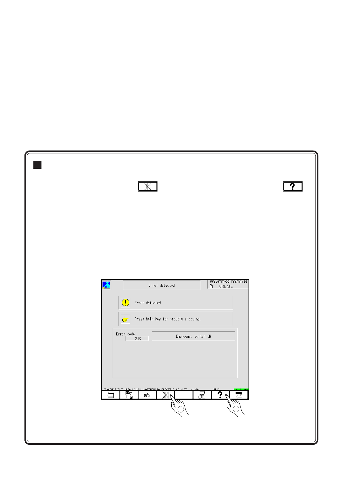
TROUBLESHOOTING
TROUBLESHOOTING
Solutions for Error
This section describes solving for errors.
Chapter 7
When the error happens, press
the touch panel or the error list on the maintenance manual, and carry out solutions.
7-1 Error Messages (Error list)
7-2 Check and Solutions
7-3 Input and Output Check of machine (Checking the sensor and movement of
movable part)
to stop the buzzer at fast. After that, see on
193C-E-OMA07-A01-01
433C-JOp-Er-001
1
2
Page 7-1
Page 90

7-1 Error Messages (Error List)
7-1-1 Errors during the Self-diagnosis
segasseMrorrE rorrEfosesuaC snoituloSdnakcehC
.nodenrutsihctiwsycnegremeehT
NOhctiwsycnegremE
FFOhctiwsovreS
porderusserpriA
.hgih
dnEnoitcudorPssecorPerP
neporevoC
nepOeegeeuqS
kcehCataD
noitceteDpirtlamrehT
.detcennocsid
.FFOdenrutsihctiwsovresehT
.elbuortasahhctiwsovresehT
.deppordsierusserpriaehT
.noitats-erpfoenihcam
.deneposirevocehT
detcennocsid
.deneposieegeeuqsehT
.tnerruc
siroelbuortasahhctiwsycnegremeehT
ootsinoitcetederusserpriafoeulavgnittesehT
ehtmorftnessilangisdnenoitcudorpehT
siroelbuortasahrevocfohctiwsehT
.detcennocsidsiroelbuortasah123dna023SL
.atadnoitcudorpnideretnesieulavlamronbaehT dna,”yfidomataD“ni”kcehcataD“tuoyrraC
revoehtstcetedrewolbehtrofhctiwslamrehtehT
.detcennocsidsiroelbuortasahnafgniloocehT
.rorrena
)0tiB:H0085(
.rorrena
)0tiB:H0085(
aPM 87.0ot aPM .
4.0otteS aPM .
.enihcam
.revocehtesolC
.rorrena
)5,4,3tiB:H0085(,)7tiB:H3905(
”tsujdaenihcaM“
.rorrena
)1,0tiB:H1905(
.noitarepo
.snafgniloocegnahC
.teserotdrawrofhctiwsycnegremeehtlluP
sitifisuhtiwtcatnocekamdnatupniehtkcehC
.NOotthgirehtothctiwsovresehtnruT
sitifisuhtiwtcatnocekamdnatupniehtkcehC
94.0foegnarehtnihtiwerusserpriaehtylppuS
noitats-erpfolangisdnenoitcudorpehtlecnaC
sitifisuhtiwtcatnocekamdnatupniehtkcehC
ni”esolc/nepoeegeeuqS“taeegeeuqsehtesolC
sitifisuhtiwtcatnocekamdnatupniehtkcehC
.eulavreporpehtretnenehtdnarorreehtkcehc
ehttratserdnalamrehtdeppirtehtlecnaC
-refeR
ecne
1-2-7
2-2-7
3-2-7
4-2-7
5-2-7
–
–
6-2-7
193C-023TE
xoBnaFrotoMrewoP
rosneserutarepmeT
noitidnocrevirD
elgnaeegeeuqS
ffoekarbsixatfiL
.detcennocsid
.)drawpu(
ffoekarbsixarednU
yalerytefaS
hcaeterusserP
.hgihootsierutarepmetehT
.rorrenasahrevirdovresehT .kcehctuptuoehttarorrerevirdehtteseR
.desserpsihctiwsycnegremeehT
.FFOdenrutsihctiwsovresehT
.eegeeuqsfoatadgnignahc
titahtkcehcdna,deloocnafgniloocehtroftiaW
.noitarepo
.detcennocsidsiroelbuortasahnafgniloocehT.snafgniloocegnahC
)2tiB:H3205(
gnitnirp(atadenihcamnidaeheegeeuqsehT
.enolautcaehtnitahtmorfsreffid)noitidnoc
.)drawpu(FFOdenrutsihctiwsneposixatfilehT
siroelbuortasahhctiwsneposixatfilehT
FFOdenrutsihctiwsnepoekarbsixaredlohehT
.detcennocsidsiroelbuortasahsixaredlohehT
.detcennocsidsiroelbuortasahyalerytefasehT
retfatuodeirractonsignihcaeterusserptnirpehT
foecnereffid±foelgnaeegeeuqsehtrof˚5
.atadenihcam
.rorrena
)2tiB:H2A05(
.rorrena
)3tiB:H2A05(
”.yfidomataD“ni
.hctiwsekarbeht)drawnwod(NOnruT
.)drawnwod(hctiwsekarbehtNOnruT
.suhtiwtcatnocekaM
ehtnihtiwsititahtoselgnaeegeeuqsehttsujdA
sitifisuhtiwtcatnocekamdnatupniehtkcehC
sitifisuhtiwtcatnocekamdna,tupniehtkcehC
.teserotdrawrofhctiwsycnegremeehtlluP
.NOebotthgirehtothctiwsovresehtnruT
7-2-7
ehttratserneht,erutarepmetreporpehtotsemoc
8-2-7
–
–
9-2-7
–
”hcaetataddorP“fo”gnihcaeterusserP“tuoyrraC
–
Page 7-2
193C-E-OMA07-A01-03
Page 91

7-1-2 Immediate Stop Error
Error Messages
segasseMrorrE rorrEfosesuaC snoituloSdnakcehC
rorrenoitingocerBCP
.deretne
rorretropsnartdraob.vnocF
.detcennocsid
rorretropsnartdraob.vnocR
.detcennocsid
rorrednetxeBCP
.mm5.0naht
.repapgninaelconsierehT
ytpmerepapgninaelC
.gninaelcroftnevlosonsierehT
.ytridsidraobehtroaremacnoitingocerehT
sitniopnoitingocerdraobfosetanidroocgnorW
.royevnoctnorfehtnosniamerdraobehT
eraroelbuortaevah242dna142HP
.royevnocraerehtnosniamerdraobehT
eraroelbuortaevah722dna522HP
eromybatadnideretsigermehtmorfsreffidB
.detcennocsidsiroelbuortasah732HP
-refeR
ecne
.noitisopreppotsehttapotstonseoddraobehT
.ezingocer-erdnagnihcniyb
ezingocer
.ylreporp
.rorrena
)2,1tiB:HB805(
.ylreporp
.rorrena
)7,5tiB:H9805(
dnaAstniopnoitingocerehtneewtebecnatsidehT
.egraltonsinoitaived–
.repapgninaelcehtteS
.rorrena
)7tiB:HA805(
.tnevlosehtylppuS
draobehttesdnahctiwsovresehtFFOnruT
draobehttesdnahctiwsovresehtFFOnruT
ehtfignitnirptuoyrracdna,yllausivtikcehC
noitisopkramnoitingocerehtotaremacehtevoM
-er,draobroaremacnoitingocerehtgninaelcretfA
01-2-7
.ezingocer-ersetanidroocreporpgniretneretfA
–
sitifisuhtiwtcatnocekamdnatupniehtkcehC
7
TROUBLESHOOTING
–
sitifisuhtiwtcatnocekamdnatupniehtkcehC
sitifisuhtiwtcatnocekamdnatupniehtkcehC
–
193C-024TE
potsytpmetnevlosgninaelC
)ksaM(noitceteDredloS
)egniryS(noitceteDredloS
.detcennocsidsiroelbuortasah612HP
.ksamehtnoredlosonsierehT
.detcennocsidsiroelbuortasah323HP
nielbaliava(.egnirysehtniredlosonsierehT
)tinuylppusredlosehtgnisu
.detcennocsidsiroelbuortasah223HP
.rorrena
sitifisuhtiwtcatnocekamdnatupniehtkcehC
)6tiB:H8805(
.ksamehtnoredlosehtylppuS
sitifisuhtiwtcatnocekamdnatupniehtkcehC
.rorrena
)3tiB:HB905(
segnirysegnahC
sitifisuhtiwtcatnocekamdnatupniehtkcehC
.rorrena
)2tiB:H1905(
–
–
–
193C-E-OMA07-A01-01
Page 7-3
Page 92

Error Messages
7-1-3 Emergency Stop Error
rorrE
edoc
7000NOhctiwsycnegremE
9000porderusserpriA
2100potsneporevoC
0200rorretsujdahtdiW
1001rorretropsnartBCP
3001
7001
1101tuoemitpueegeeuqsF
3101tuoemitpueegeeuqsR
6101
rorre
7101
rorre
8101rorrEgninoitisoPBCP.gnorwsiataddraoB
segasseMrorrE rorrEfosesuaC snoituloSdnakcehC
.nodenrutsihctiwsycnegremeehT
siroelbuortasahhctiwsycnegremeehT
noitcetederusserpriafoeulavgnittesehT
siroelbuortasahhctiwsrevocehT
.gnorwsiataddraobfo)W(ezisehT
.detcennocsidsiroelbuortasah141HP
tropsnartehtnosniamerdraobehT
rO(.tinodraobonsierehtroroyevnoc
foedisesreverehtottifsidraobehT
.detcennocsidsiroelbuortasah441HP
roelbuortaevah742dna,322,331HP
eraroelbuortaevah173,073LYC
htdiwroyevnoctfeL
tuoemiTtnemtsujda
htdiwroyevnocretneC
tuoemiTtnemtsujda
htdiwroyevnocthgiR
tuoemiTtnemtsujda
nwodelzzongninaelC
puelzzongninaelC
.detcennocsid
.deppordsierusserpriaehT
.hgihootsi
.deneposirevocehT
.detcennocsid
.tnirpot)W(ezis
).asreveciv
.ksam
.rorrenasahrevirdhtdiwehT
.detcennocsidera
.deppordsierusserpriaehT
.detcennocsid
.detcennocsid
.deppordsierusserpriaehT
eraroelbuortasah632,532SL
.detcennocsid
.deppordsierusserpriaehT
)0tiB:H0085(
4.0otteSaPM
.revocehtesolC
draobehtfotuotessinipredlohdraobehT
)1tiB:H3805(
)4tiB:H3805(
eraroelbuortaevah723,623,523,423SL
aPM.
.detcennocsideraroelbuortaevah371LV
aPM.
)7,6,5,4tiB:H1905(
)1,0tiB:H2105(
)6,5tiB:HA805(
)3tiB:H2005(
.teserotdrawrofhctiwsycnegremeehtlluP
.rorrenasitifisuhtiwtcatnocekamdnatupniehtkcehC
5.0foerusserpriaehtylppuS aPM8.0otaPM
.rorrenasitifisuhtiwtcatnocekamdnatupniehtkcehC
)5,4,3tiB:H0085(,)7tiB:H3985(
.tnirpot)W(ezisdraobehtnihtiwnipredlohdraobehtteS
.)W(ezisataddraobreporpehtretnE
.rorrenasitifisuhtiwtcatnocekamdnatupniehtkcehC
ehttupro,royevnocehtnodeniamerdraobehtevomeR
.noitisopdeificepsehttadraob
.ksamfoedisesreverehtmorfdraobehtevomeR
.rorrenasitifisuhtiwtcatnocekamdnatupniehtkcehC
.rorrenasitifisuhtiwtcatnocekamdnatupniehtkcehC
)3,1tiB:H3A05(,)5tiB:H2A05(
.rorrenasitifisuhtiwtcatnocekamdnatupniehtkcehC
)7tiB:HB805(,)3tiB:H9805(,)3tiB:H2805(
94.0foerusserpriaehtylppuS aPM87.0ot.aPM
.rorrenasitifisuhtiwtcatnocekamdnatupniehtkcehC
.rorrenasitifisuhtiwtcatnocekamdnatuptuoehtkcehC
94.0foegnarehttaerusserpriaehtylppuS aPM87.0ot
.rorrenasitifisuhtiwtcatnocekamdnatupniehtkcehC
.rorrenasitifisuhtiwtcatnocekamdnatuptuoehtkcehC
tesffoerusserpdraobehtroatadssenkcihtdraobkcehC
”.retemarapenihcaM“rof
94.0foegnarehttaerusserpriaehtylppuS aPM87.0ot
(1/2)
-refeR
ecne
1-2-7
3-2-7
5-2-7
–
–
–5001
–
–
–
2201rorrenigiroredlohBCP
3201revoaeraelbatnirP
8201esolcredloheegeeuqS
193C-025TE
Page 7-4
.tifoegnar
.detcennocsid
.detcennocsid
.detcennocsidsiroelbuortasah512SL
.detcennocsidsiroelbuortasah681LV
tnarelotehtrevosiatadnoitisoptnirP
.deppordsierusserpriaehT
aPM.
siroelbuortasah123,023SL
siroelbuortasah181,081LV
)5tiB:H8805(
)6tiB:H3005(
”.yfidom
94.0foegnarehttaerusserpriaehtylppuS aPM87.0ot
)1,0tiB:H1905(
)1,0tiB:H3005(
193C-E-OMA07-A01-02
.rorrenasitifisuhtiwtcatnocekamdnatupniehtkcehC
–
.rorrenasitifisuhtiwtcatnocekamdnatuptuoehtkcehC
ataD“ni”atadsoptnirP“ehtmorfeulavreporpehtretnE
–
.rorrenasitifisuhtiwtcatnocekamdnatupniehtkcehC
–
.rorrenasitifisuhtiwtcatnocekamdnatuptuoehtkcehC
Page 93
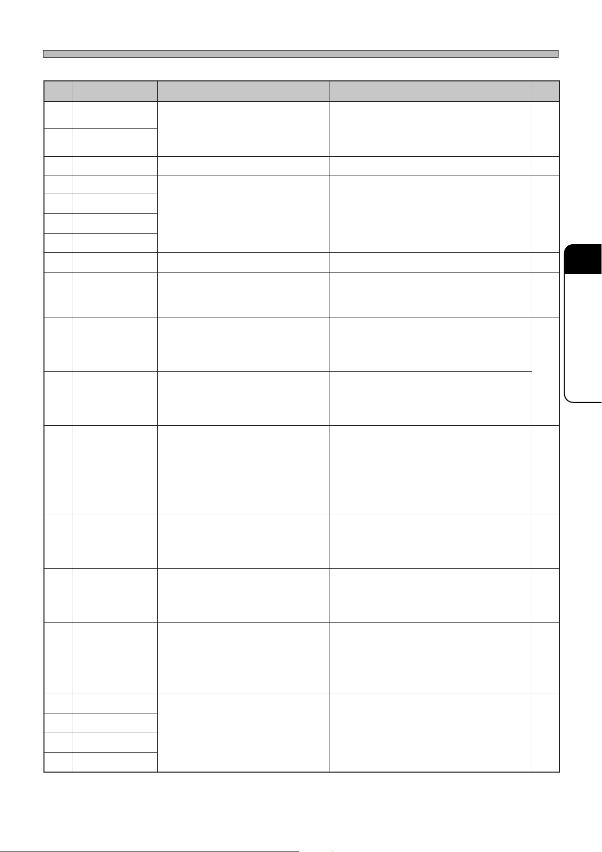
Error Messages
(2/2)
rorrE
edoc
8301
rorre
9301
rorre
6501nwodCD.eulavdeificepsehtnahtrewolsiegatlovCD.suhtiwtcatnocekaM–
0011GNtestinugninaelC
1011
rorre
2011
rorre
3011
rorre
9011rorreataderusserP
0111
rorrE
1111ffOekarBtfahSretfiL
2111
3111
θnurrevO)+(tfahS
4111
θnurrevO)-(tfahS
5111
6111rorrEmuucaVBCP
F→royevnoCR
7111
8111
C→royevnoCR
9111
1211
193C-026TE
ffOekarB
rorrE
rorrE
rorrE
segasseMrorrE rorrEfosesuaC snoituloSdnakcehC
nwodeegeeuqsF
nwodeegeeuqsR
noitisoptinugninaelC
elpuoctinugninaelC
dexiftinugninaelC
noitingoceretsaP
tfahSdrauGrednU
nruteRreppotSBCP
rorrEtropsnarT
royevnoCretneC
rorrEtropsnarT
rorrEtropsnarT
draob.vnocR
rorretropsnart
.detcennocsid
.nrettap
.)drawpu(
.detcennocsid
.)drawpu(FFO
.detcennocsid
.reppotsdraob
.noitisop
.noitisop
.sporderusserpriaehT
eraroelbuortaevah713dna613HP
.noitisopreporpehttatonsitinugninaelcehT
aevah532,232,132SL,332,032,721HP
.detcennocsideraroelbuort
tnarelotehtrevosierusserptnirptesehT
.erawdrahfoegnar
.detelpmocylreporpsinoitingocerredlosehT
thguatehtsatuodeirractonsigniredlosehT
FFOdenrutsihctiwsneposixatfilehT
siroelbuortasahhctiwsneposixatfilehT
denrutsihctiwsnepoekarbsixaredlohehT
siroelbuortasahsixaredlohehT
ehtgnisuninwodebottpeksireppotsehT
.detcennocsidsiroelbuortasah512SL
.detcennocsidsiroelbuortasah781LV
ehttasielbatY-XehTθ+nurrevosixa
.detcennocsidsiroelbuortasah531HP
ehttasielbatY-XehTθ-nurrevosixa
.detcennocsidsiroelbuortasah631HP
.pudekciptonsidraobehT
.sneppahegakaelriaehT
.detcennocsidsiroelbuortasah711HP
sierehtroroyevnocehtnosniamerdraobehT
).asrevecivrO(.tinodraobon
342,242,142,722,622,522,441,341HP
.detcennocsideraroelbuortaevah
87.0 aPM .
94.0foegnarehttaerusserpriaehtylppuS aPM ot
nasitifisuhtiwtcatnocekamdnatupniehtkcehC
.rorre
)7,6tiB:H0905(
.ylreporptinuehttesdnahctiwsovresehtFFOnruT
nasitifisuhtiwtcatnocekamdnatuptuoehtkcehC
.rorre
)6,5,3,2,1,0tiB:HA805(,)7tiB:H1805(
ataddorP“fognihcaeterusserptnirpehttuoyrraC
.eulavreporpehttesdna”,yfidomataD“ni”hcaet
gnihcaetnoitingocerredlosdnaksamehttuoyrraC
.niaga
tiylppusdna,ksamehtnoredlosdeniamerehtkcehC
.yrassecen
.hctiwsekarbeht)drawnwod(NOnruT
nasitifisuhtiwtcatnocekamdnatupniehtkcehC
.rorre
)2tiB:H2A05(
.hctiwsekarbeht)drawnwod(NOnruT
nasitifisuhtiwtcatnocekamdna,tupniehtkcehC
.rorre
)3tiB:H2A05(
94.0foegnarehttaerusserpriaehtylppuS aPMot
87.0aPM.
nasitifisuhtiwtcatnocekamdnatupniehtkcehC
.rorre
)5tiB:H8805(
nasitifisuhtiwtcatnocekamdnatuptuoehtkcehC
.rorre
)7tiB:H3005(
sixaatehtehtevomdnahctiwsovresehtFFOnruT
.dnahybnoitisopnurrevo)+(ehtmorf
nasitifisuhtiwtcatnocekamdnatupniehtkcehC
.rorre
)5tiB:H2805(
sixaatehtehtevomdnahctiwsovresehtFFOnruT
.dnahybnoitisopnurrevo)-(ehtmorf
nasitifisuhtiwtcatnocekamdnatupniehtkcehC
.rorre
)6tiB:H2805(
draobehtteserdna,hctiwsovresehtFFOnruT
.ylreporp
.tinumuucavehtnonoitisopmuucavriaehtrevoC
nasitifisuhtiwtcatnocekamdnatupniehtkcehC
.rorre
)7tiB:H0805(
nasitifisuhtiwtcatnocekamdnatupniehtkcehC
.rorre
)3,2,1tiB:HB805(,)7,6,5tiB:H9805(,)4,3tiB:H3805(
-refeR
ecne
–
–
7
–
TROUBLESHOOTING
–
9-2-7
–
–
–
–
.ylreporpdraobehttesdnahctiwsovresehtFFOnruT
–
193C-E-OMA07-A01-02
Page 7-5
Page 94
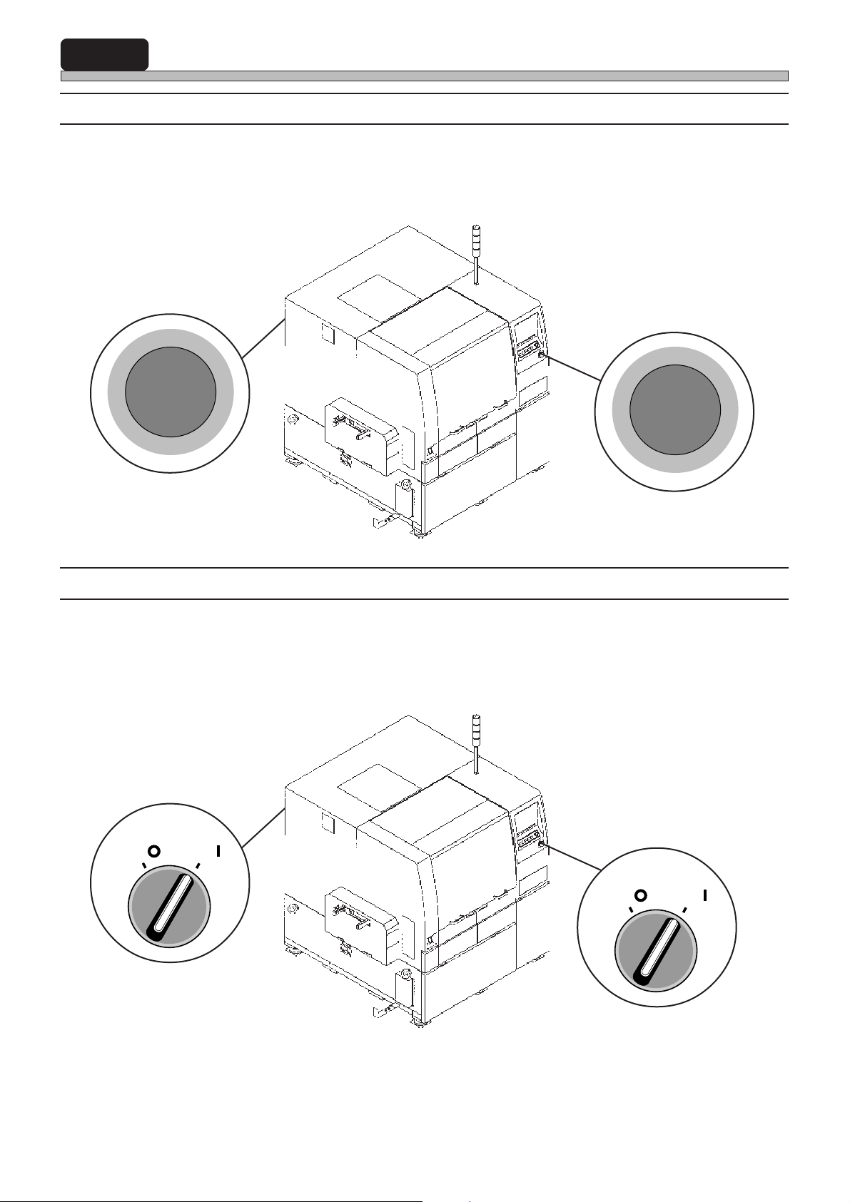
7-2 Check and Solutions
E
M
E
R
G
E
N
C
Y
S
T
O
P
7-2-1 Emergency Switch On
1. Resetting the emergency switch.
Pull the switch forward to reset.
G
E
R
N
C
Y
P
T
O
E
M
E
S
Front side of machine (1 point)
7-2-2 Servo Switch
1. Turn ON the servo switch.
Turn the switch to the right.
SERVO
OFF ( )
ON ( )
193C-AA00
Front side of machine (1 point)
SERVO
OFF ( )
ON ( )
Rear side of machine (1 point)
Page 7-6
193C-AA00
Operation panel on front side of machine
193C-E-OMA07-A01-02
Page 95
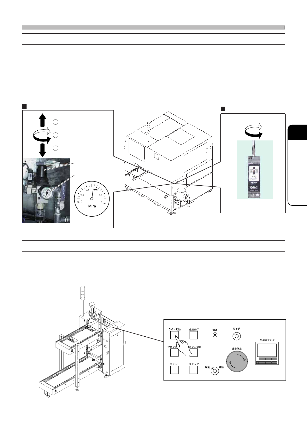
7-2-3 Air Pressure Drops
LINE
START
PROD.
END
PUT IN
MAGAZINE
RESET
STEP
TAKE OUT
MAGAZINE
POWER
MANU.
PITCH
EMERGENCY
PRODUCTION
COUNTER
R
S
E
T
E
R
S
E
T
E
1234
AUTO
1. Adjusting the air pressure
If the proper air pressure [more than 0.49 MPa to 0.78 MPa] is not supplied, adjust the pressure to
the specified one in the following order.
2. Setting the air pressure detection value
If the air pressure is not set to the specified one, [0.4 MPa], set it to the specified air pressure
detecting value in the following way.
Air pressure adjustment
1
Unlock
Check and Solutions
Air pressure adjustment
2
Adjust
3
Lock
Valve
Pressure gauge
193C-AB00
193C-007P
7-2-4 Pre Process Production End
1. Canceling the production end signal
As the production end signal is output from the front stocker of slotted magazine loader or stacking
magazine loader, press the LINE START switch to cancel the production end signal.
Adjust
3Y3C-089P
7
TROUBLESHOOTING
193C-E-OMA07-A01-02
Operation panel on top face
033C-PS006
Page 7-7
Page 96
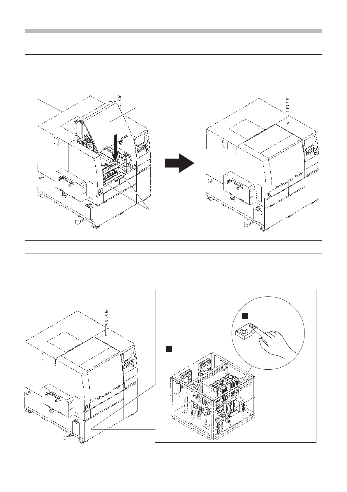
Check and Solutions
7-2-5 Cover Open
1. Closing the safety cover
Check that the safety cover indicating the error is not opened, and close it if it is opened.
Middle safety cover
Front safety cover
193C-AC00
Rear safety cover
7-2-6 Thermal Trip Detection
1. Resetting the thermal switch for the blower
Remove the front cover on the power box, and press the reset button. Make contact with us if the
same error is detected after resetting.
193C-AA00
Thermal switch
Power box
193C-009E
193C-AA00
Page 7-8
330DC0AB00
193C-E-OMA07-A01-01
Page 97
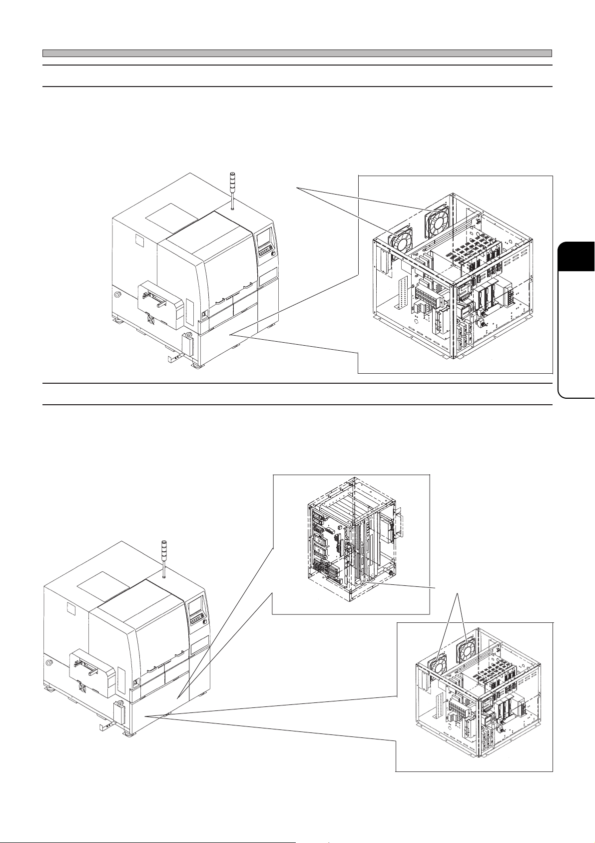
7-2-7 Power Box Fan Motor
1. Checking the movement of cooling fan
If the wind is not sent from the opening of cooling fan to the outside, the cooling fan may has a
trouble. Make contact with us for changing it.
Cooling fan
Check and Solutions
7
TROUBLESHOOTING
193C-AA00
7-2-8 Temperature Sensor
1. Checking the movement of cooling fan
If the wind is not sent from the opening of the cooling fan to the outside, it can be thought the
trouble or clogging of dust in the cooling fan. As for the trouble, make contact with us for changing
it, and clean around the fan for the clogging.
33T9C1AB00
330DC0AB00
Cooling fan
Reverse side of CPU box
193C-AA00
193C-E-OMA07-A01-01
330DC0AB00
Reverse side of power box
Page 7-9
Page 98
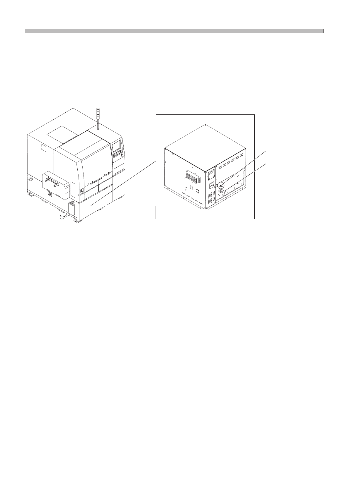
Check and Solutions
7-2-9 Lift Axis Brake off
Under Axis Brake off
1. Turning ON (downward) the brake switch
The switch at the lower position is ON.
Lift axis brake
Under axis brake
193C-AA00
330DC0AA00
Page 7-10
193C-E-OMA07-A01-01
Page 99
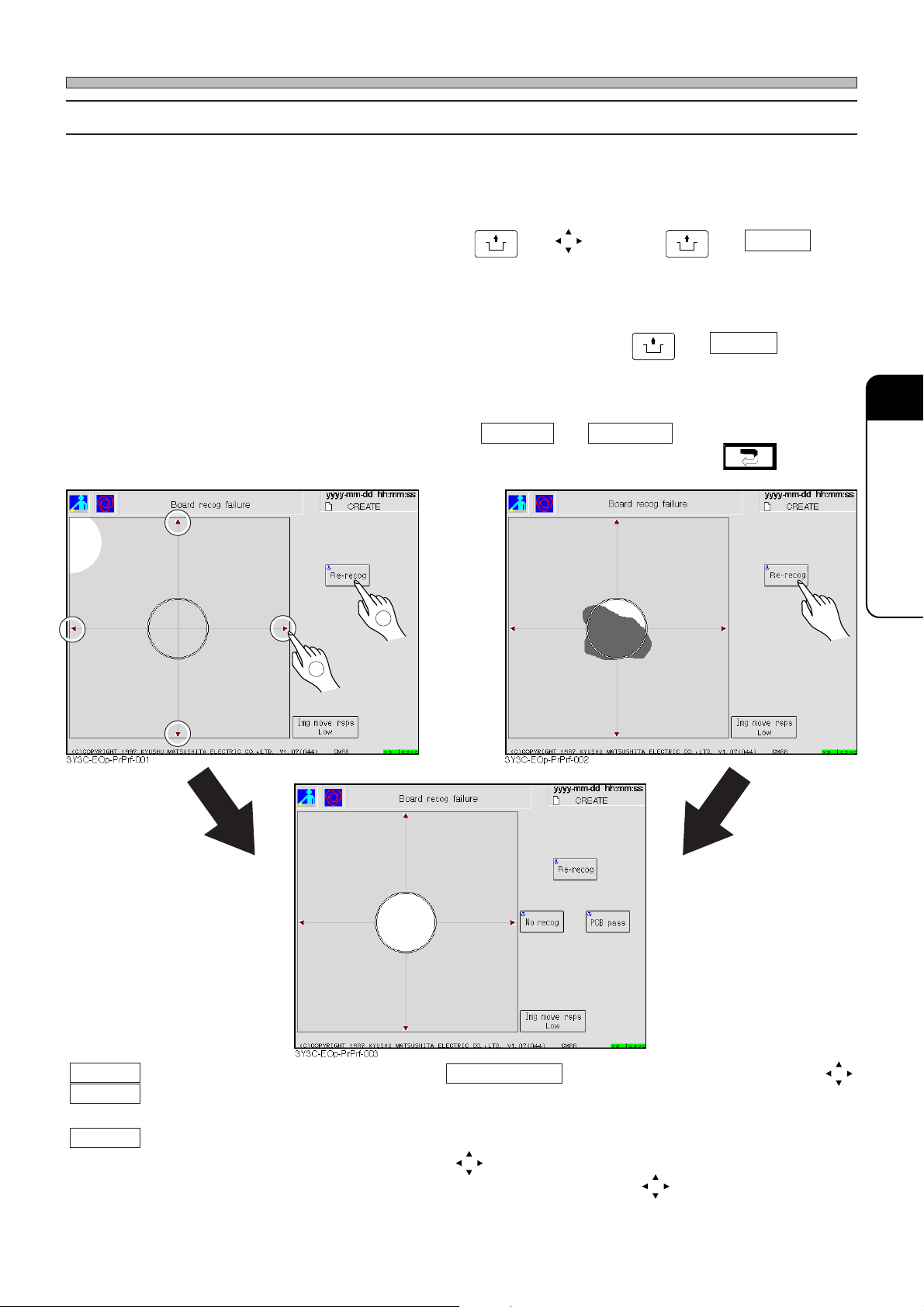
7-2-10 PCB Recognition Error
1. Moving the camera to the recognition mark position by inching and recognize again. (Fig. 1)
Check the error screen, and when the recognition mark is not at the center of recognition screen,
move the recognition mark to the center by
operation is restarted.
2. Re-recognizing the recognition camera or board after cleaning
Check the error screen, and clean the mark if it is dirty, then press
operation is restarted.
UNLOCK
and , and press
Check and Solutions
UNLOCK
and Re-recog . The
UNLOCK
and Re-recog . The
3. Re-recognizing after entering proper coordinates
∗ When the recognition error is found again, No recog and PCB board are displayed additionally.
Select either of them (Fig. 3). To quit automatic operation and teaching, press .
(Fig. 2)(Fig. 1)
2
1
(Fig. 3)
7
TROUBLESHOOTING
Re-recog The board recognition is carried out again.
No recog The next movement is carried out without
recognition.
Pass The recognition error board is passed
during the automatic operation.
193C-E-OMA07-A01-04
Img move rsps The moving distance of one pressing
is set.
Low : 0.01 mm, Middle : 0.1 mm,
High : 2.00 mm
(red arrow mark) The recognition screen moves to
the (red arrow mark) direction.
Page 7-11
Page 100
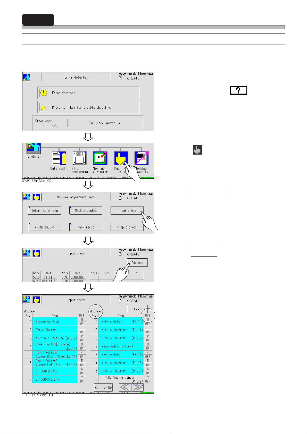
7-3 The Input and Output Check of Machine
7-3-1 Input Check after Error
The trouble in the sensor can be thought as one reason to make errors.
This section describes checking the proper input state (ON and OFF) of the sensor related to that
error.
1. Check the error message.
• Check solutions by the of the touch
panel or in the error message list in the mainte-
nance manual.
2. Return to the main menu.
193C-EOp-Er-001
193C-EEn-Ma-001
193C-EEn-MaIc-002
3. Press
• The machine adjustment screen appears.
Machine adj
.
4. Press Input check .
• The list screen of input check appears.
5. Press Address .
• The address screen of input check appears.
Page 7-12
6. Check that the bit (• • • • H : Bit •) of
address described in the solutions is
proper (ON and OFF).
• If the input state of sensor is not proper, a
trouble or disconnection can be thought. Make
contact with us for changing.
193C-E-OMA07-A01-01
 Loading...