

Panasonic SL-VMEL-Q Instruction Manual

INSTRUCTION MANUAL
VMEL-Q
Flexible Wire-saving Link System S-LINK V
Mitsubishi Electric Corportaion PLC MELSEC-Q Series
Bus Direct-connection Type S-LINK V Controller
SL-
MJE-SLVMELQ No.0071-18V

MEMO
1. INTRODUCTION
WARNING
Thank you very much for purchasing Panasonic products. Read this Instruction Manual carefully
and thoroughly for the correct and optimum use of this product. Kindly keep this manual in a convenient place for quick reference.
● Never use this product in a device for personnel protection.
● In case of using devices for personnel protection, use products which meet laws and standards, such
as OSHA, ANSI or IEC etc., for personnel protection applicable in each region or country.
● Before touching this product, remove any electrostatic charge that may be present on your body.
There is a danger of this product getting damaged due to the electrostatic charge.
2. CAUTIONS
Power supply
● This product has no short-circuit protective function. Use a power supply having a short-circuit
protective function (e.g. fuse, etc. ).
● Verify that the supply voltage variation is within the rating. Also, verify the voltage variation at
the end terminal of the transmission route, since voltage drop occurs depending on the diameter or the length of the transmission cable.
● If power is supplied from a commercial switching regulator, ensure that the frame ground (F.G.)
terminal of the power supply is connected to an actual ground.
● Do not use during the initial transient time after the power supply is switched ON. Transmission
is not performed when the system is in BUSY condition (at the time of turning the power ON or
setting the system).
● Make sure to use an isolation transformer for the DC power supply. If an auto-transformer (single winding transformer) is used, this product or the power supply may get damaged.
● In case a surge is generated in the power supply used, connect a surge absorber to the supply
and absorb the surge.
Wiring
● Do not run the wires together with high-voltage lines or power lines or put them in the same
raceway. This can cause malfunction due to induction.
● Make sure to carry out the installation and wiring in the power supply OFF condition.
● In order to reduce noise, make the wiring as short as possible.
● Always use the specied transmission cable.
● Take care wrong wiring will damage the product.
● Take care that if connect +24V-0V to 0V-G of this product by mistake, blown fuse of internal cir-
cuit protection will occur. The blown fuse cannot be restored.
Environment
● This product has been developed / produced for industrial use only.
● In case noise generating equipment (switching regulator, inverter motor, etc.) is used in the
vicinity of this product, connect the frame ground (F.G.) terminal of the equipment to an actual
ground.
● This product does not have a dust-proof or water-proof construction. Do not use it in a place
having excessive vapor, dust, etc. or a place where the product may be come in contact with
oil, water, chemicals or organic solvents. Furthermore, do not use it in an environment having
corrosive gas.
● Do not use the product in places where the ambient temperature or the humidity exceeds the
specications.
Terminal
● Do not tighten the screws with a torque exceeding the specications.
1
Others
For the details of MELSEC-Q, refer to “MELSEC-Q
The contents described in this manual are only about the
S-LINK V User’s Manual
● Please refer to “
● Any protective devices or safety circuits against system malfunction should be designed to be
external to the system.
● To use this product together with the PLC (programmable logic controller) manufactured by Mit-
subishi Electric Corporation and to conform to the requirements of the EMC order, observe the
following items.
(1) Install the system while referring to the “PLC User’s Manual” prepared by Mitsubishi Electric
Corporation.
(2) Be sure to put this product in a conductive box.
(3) Install a ferrite core to the cable (including the main line in
● There are some cases that even if the power indicators of other units are turned OFF when the
PLC is turned ON or OFF, the power indicator (POWER) of this product may not be turned OFF.
This is not a malfunction or an error.
S-LINK V User’s Manual
” for details of the system design.
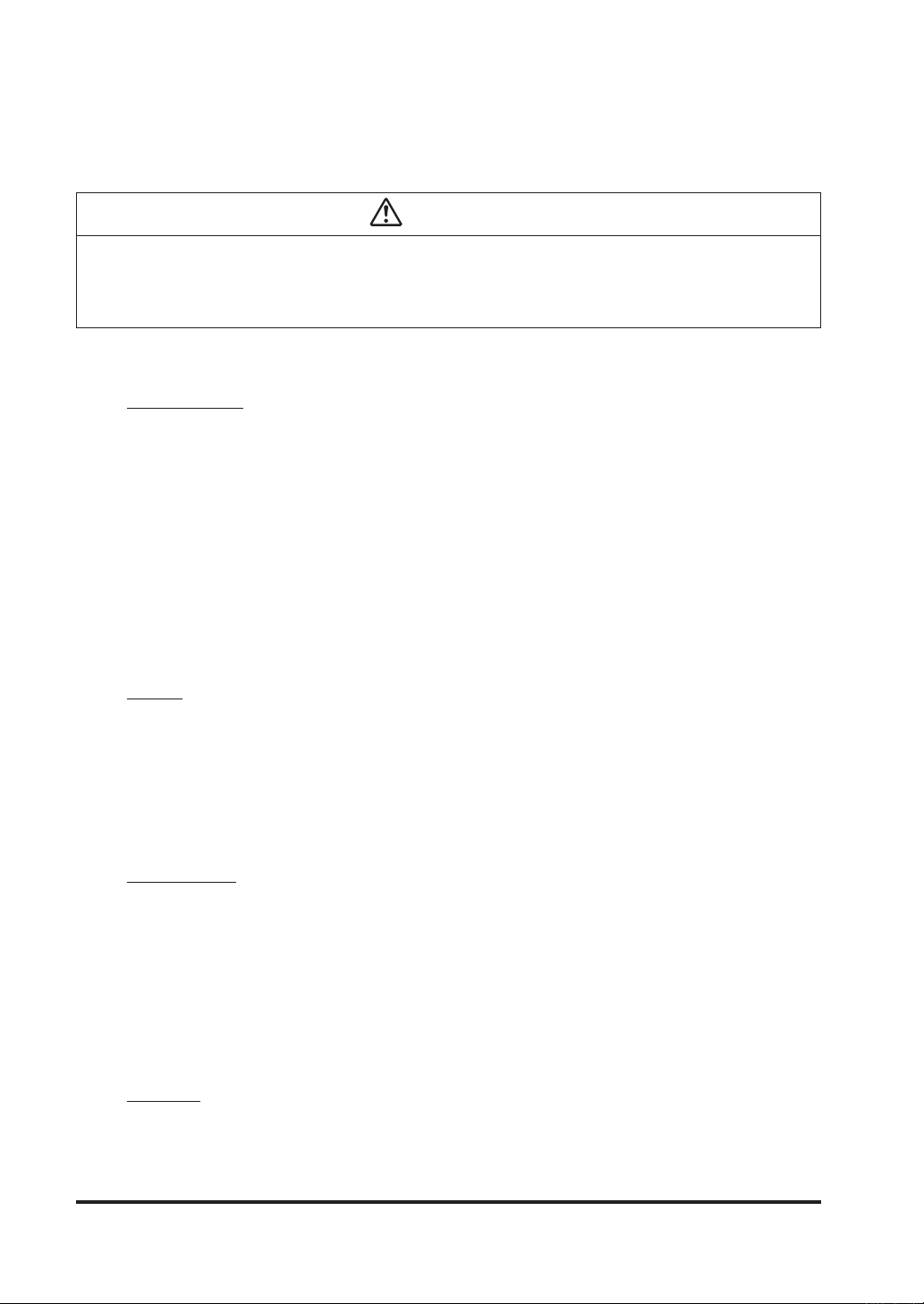
3. ExampleofSystemConguration
Following is an example of system conguration for
S-LINK V
Manual” prepared by Mitsubishi Electric Corporation.
setting and wiring of this product.
S-LINK V
unit.
system) if required.
Mitsubishi Electric Corporation
MELSEC-Q Series
For the details of each unit, refer to “
Wiring of S-LINK V system
.”
2
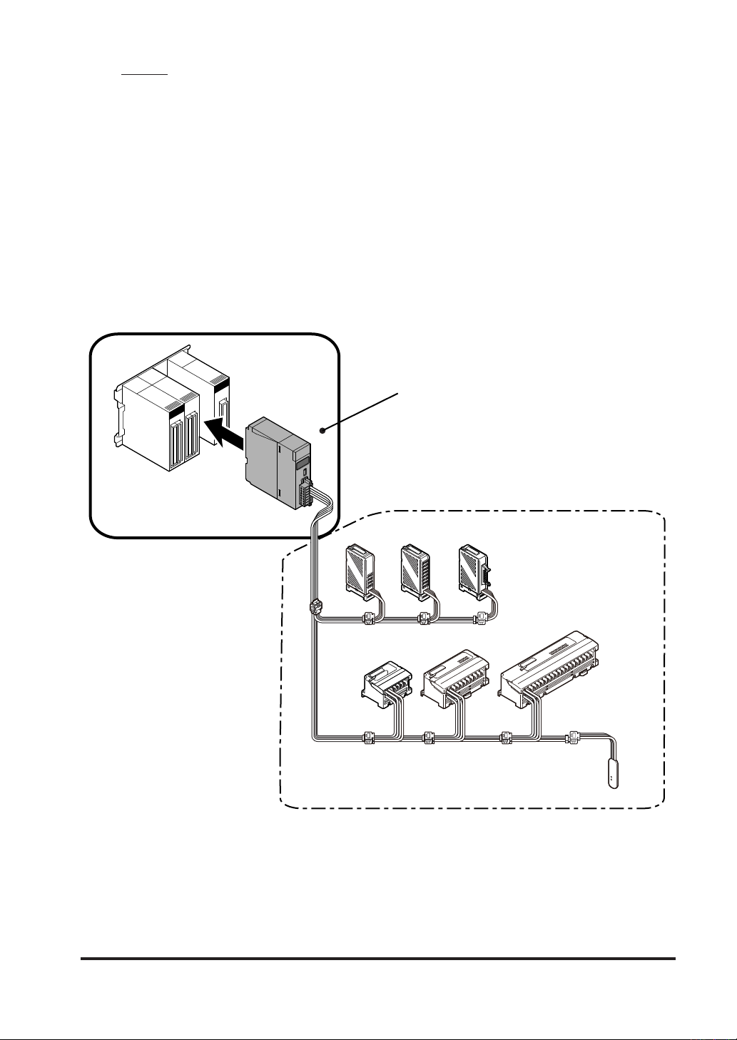
4. FUNCTIONAL DESCRIPTION
terminal block connector
6. Transmission mode
9. Power indicator (Green)
10. RUN indicator (Green)
4. SELECT keys
5. MODE selector switch
SL-VMEL-Q
POWER
RUN
CHECK
G
D
0
24
0
24
FG
SEND
ERRORRUN
HEX
ENTER
indicator (Green)
7. Error indicataor (Red)
1. Hexadecimal number display
mode indicataor (Green)
2. Address display (Red)
3. ENTER key
8. S-LINK V
3
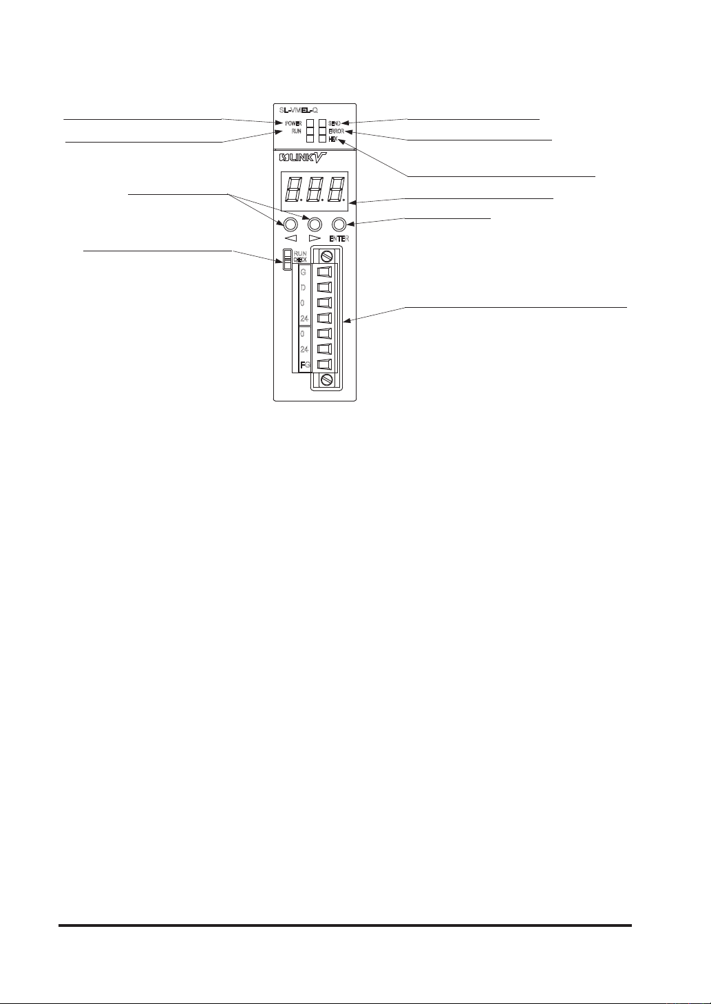
No. Designation Function
Mode
Mode
Mode
Hexadecimal number
1
display mode indicator
(Green)
2 Address display (Red)
Indicates the current display mode of the address display.
• ON: Hexadecimal number display mode is selected.
• OFF: The decimal number display mode is selected.
The displayed item depends on the mode (“RUN,” “CHECK,” or “CONFIG” mode).
Use the mode selector switch to switch the mode.
<RUN mode>
• Each transmission mode (3 modes in total) will be indicated by the following character,
and the LED of each character will sequentially light up just like rotating clockwise.
• If an error occurs, the error message will appear.
Note : After eliminating the cause of the error, press ENTER key and SELECT
keys (2 types of keys) at the same time.
<CHECK mode>
• The number of connected nodes will be displayed rst.
SELECT key is pressed, the recognized addresses will be displayed one after another.
Number of connected nodes:
Using the decimal or hexadecimal number, the number of I/O units' nodes
will be displayed.
Address:
Using the decimal or hexadecimal number, the addresses of the I/O units
will be displayed sequentially.
Note: In the hexadecimal number display mode, the hexadecimal number indi-
cator (green) will light up.
• If an error occurs, the number of nodes having the error and the error addresses will be displayed sequentially (for errors 3, 4, and 5).
The error message will disappear.
After that, each time
<CONFIG mode>
• Settings will be displayed sequentially. To switch the displayed setting, use SELECT key.
• When RUN mode is switched to CONFIG mode, dierent item will be displayed compared with the displayed item just after power-ON.
If setting the operation at PLC halt condition to transmission halt, and when the
PLC is halted, “ ” is displayed in RUN mode and CHECK mode, while each
item can be conrmed in CONFIG mode. In case setting the operation at PLC halt
condition to “transmission continued,” content of each item is displayed.
<RUN and CHECK modes>
3 ENTER key
4 SELECT keys
5 MODE selector switch Switches the mode (RUN, CHECK, or CONFIG mode).
Transmission mode
6
indicator (Green)
7 Error indicator (Red)
S-LINK V
8
connector
9 Power indicator (Green) Lights up when the power is supplied from the PLC to this product.
10 RUN indicator (Green)
terminal block
Press ENTER key to determine the set condition value.
In the system setting mode, press and hold ENTER key for 3 seconds or more,
then the system will be set.
Use these keys to switch the displayed item or set item. Also use these keys
to change the set condition value.
This indicator will blink during transmission (during the transmission signal is
being output). The indicator blinking cycle depends on the transmission mode.
(A mode: fast ↔ C mode: slow)
The indicator indicates the error status as follows:
• Lights up when an error occurs.
• Blinks when the cause of the error is eliminated.
• Turns OFF when operation is normal.
Receives +24V, 0V, and F.G. from the external power supply unit, and supplies
+24V, 0V, D, and G to the I/O units.
Lights up when this product is running (Xn0 = ON at the same time). Also
lights up when transmission with the CPU unit is started.
4
Base unit 1
Unit connector
2
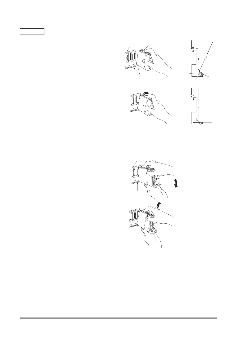
5. MOUNTING
Base unit
Unit
connector
Mounting
1. Insert the unit fixing projection of this
product into the unit fixing hole of the
base unit.
2.
Push the product in the direction of the
arrow, and t it on the base unit.
3. Check if the product is completely fitted
on the base unit.
Notes: 1) Make sure to insert the xing projection
Dismantling
1. Hold the product with both hands and
2. While pushing the hook, pull the product
3. While lifting up the product to the upper
Note : In case the product is mounted with
into the xing hole to mount the product. Take care that if you forcibly mount
the product without inserting the projection into the hole, connector of the
product and the base unit can break.
2) In case using the product in a place
having excessive vibration or shock,
mount the product on the base unit
with M3 (length 12mm) screws (please
arrange separately).
push the upper hook of the product until
the product stops.
to your side.
side, remove the xing projection of the
product from the xing hole.
screws, make sure to remove the screws
rst, and then remove the xing projection
from the unit xing hole. Take care that if
you forcibly remove the product from the
base unit, the product can break.
Base unit Unit
Unit fixing hole
Unit fixing hole
1
Unit fixing
projection
2
Unit fixing
projection
Unit fixing hole
Unit
3
5
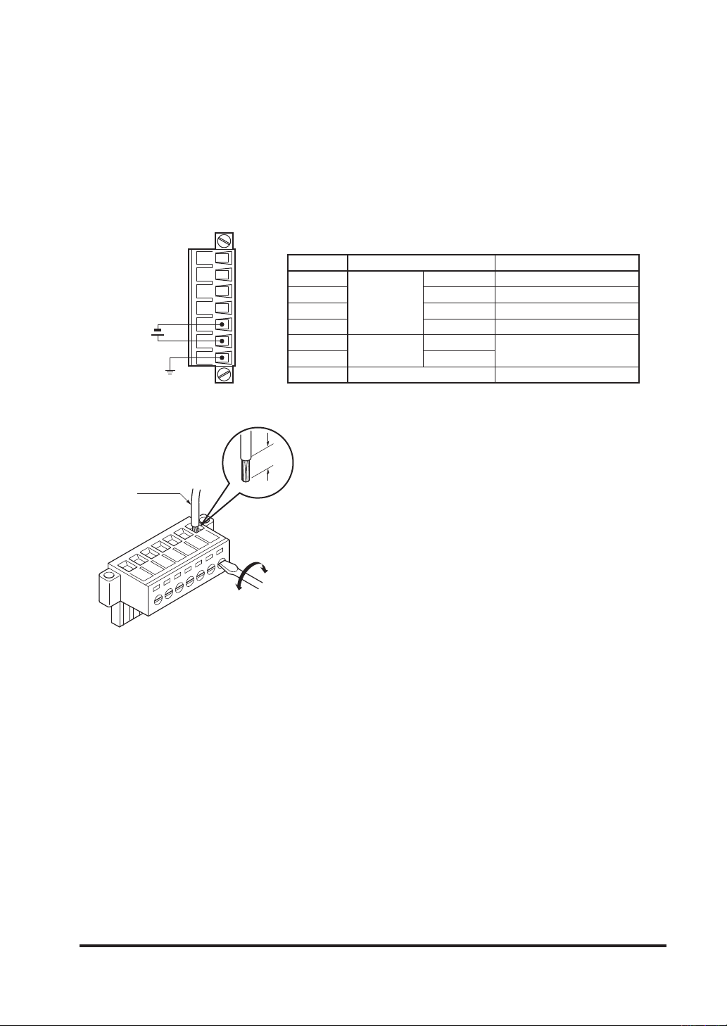
6. CONNECTION
24V DC
+10
- 5
Wire processing dimension
(Width = 3.8mm or less, thickness = 0.7mm or less)
● Take care that wrong wiring will damage the product.
● Do not short-circuit “0V” and “G” on the S-LINK V terminal block connector side.
● A large current may ow through the external power supply input, depending on the load.
Use wires having sucient current capacity. Further, when supplying power to the load from
this product, make sure not to exceed the allowable through current.
● Tighten the screws of the ange also, so that the terminal block connector does not come out.
The tightening torque should be 0.2N·m, or less.
Do not apply solder, etc., on the tips of the wires to be connected to the S-LINK V terminal
block connector. This can cause loosening of the screws, resulting in wire disconnection.
G
7
D
6
0V
5
24V
−
%
+
24V
4
0V
3
2
FG
1
No.
7
6
5
4
3
2
1
● Process and tighten the wires as follows.
7mm
Terminal block
Main line in
S-LINK V
system
Input
G
D
0V
+24V
0V
+24V
F.G.
Description
Black
White
Blue
Brown
External power input
Frame ground
Lead wire
Loosen
Tighten
<Tightening torque>
0.4N·m or less
Recommended tool: Small-sized flathead screwdriver
6

7. BuerMemory
ON / OFF data for each unit on S-LINK V system, error addresses, and number of connected
units on S-LINK V system are stored in buer memory within the product.
Buermemorycongurationofthisproduct
Address
K0
to
K31
K32 I/O control points FROM order only
K33 I/O setting 0 to 3 FROM order only
K34 S-LINK V I/O unit connected nodes FROM order only
K35
to
K66
K67 Number of nodes of error 3 FROM order only
K68
to
K99
K100 Number of nodes of error 4 FROM order only
K101
to
K132
K133 Number of nodes of error 5 FROM order only
K134
to
K165
K166
K167
K168
K169
K170
K171
K172
K173
K174
K175
K176
K177
K178
to
K184
Note: Set a date of CPU in the PLC to store dates that error 1 to 6 occurs.
I/O data of S-LINK V I/O unit (for 512 addresses)
S-LINK V system connected I/O unit address
Error 3 I/O unit address (for 512 units) FROM order only
Error 4 I/O unit address (for 512 units) FROM order only
Error 5 I/O unit address (for 512 units) FROM order only
Date that Error 1 occurs (month, day, time, minute)
(Note)
Date that Error 2 occurs (month, day, time, minute)
(Note)
Date that Error 3 occurs (month, day, time, minute)
(Note)
Date that Error 4 occurs (month, day, time, minute)
(Note)
Date that Error 5 occurs (month, day, time, minute)
(Note)
Date that Error 6 occurs (month, day, time, minute)
(Note)
Allocation FROM / TO order
Input: FROM order only
Output: TO order (FROM order can be
performed as well)
(for 512 units)
Program setting reading
TO order (FROM order can be performed as well)
FROM order only
FROM order only
FROM order only
FROM order only
FROM order only
FROM order only
FROM order only
7

1) I/O data of S-LINK V I/O unit
It is I/O data area of
In case of setting to input, bit corresponding to each address will be set to “1” when
input unit is ON. Read the input data in “FROM” order. (in case not in
mission, input data maintains the former states.)
In case of setting to output, when write “1” to corresponding bit of each
address, output of
I/O data of S-LINK V I/O unit
bit 15 14 13 12 11 10 9 8 7 6 5 4 3 2 1 0
K0 15 14 13 12 11 10 9 8 7 6 5 4 3 2 1 0
K1 31 30 29 28 27 26 25 24 23 22 21 20 19 18 17 16
K2 47 46 45 44 43 42 41 40 39 38 37 36 35 34 33 32
K3 63 62 61 60 59 58 57 56 55 54 53 52 51 50 49 48
K4 79 78 77 76 75 74 73 72 71 70 69 68 67 66 65 64
K5 95 94 93 92 91 90 89 88 87 86 85 84 83 82 81 80
K6 111 110 109 108 107 106 105 104 103 102 101 100 99 98 97 96
K7 127 126 125 124 123 122 121 120 11 9 118 117 11 6 115 114 11 3 112
K8 143 142 141 140 139 138 137 136 135 134 133 132 131 130 129 128
K9 159 158 157 156 155 154 153 152 151 150 149 148 147 146 145 144
K10 175 174 173 172 171 170 169 168 167 166 165 164 163 162 161 160
K11 191 190 189 188 187 186 185 184 183 182 181 180 179 178 177 176
K12 207 206 205 204 203 202 201 200 199 198 197 196 195 194 193 192
K13 223 222 221 220 219 218 217 216 215 214 213 212 211 210 209 208
K14 239 238 237 236 235 234 233 232 231 230 229 228 227 226 225 224
K15 255 254 253 252 251 250 249 248 247 246 245 244 243 242 241 240
K16 271 270 269 268 267 266 265 264 263 262 261 260 259 258 257 256
K17 287 286 285 284 283 282 281 280 279 278 277 276 275 274 273 272
K18 303 302 301 300 299 298 297 296 295 294 293 292 291 290 289 288
K19 319 318 317 316 315 314 313 312 311 310 309 308 307 306 305 304
K20 335 334 333 332 331 330 329 328 327 326 325 324 323 322 321 320
K21 351 350 349 348 347 346 345 344 343 342 341 340 339 338 337 336
K22 367 366 365 364 363 362 361 360 359 358 357 356 355 354 353 352
K23 383 382 381 380 379 378 377 376 375 374 373 372 371 370 369 368
K24 399 398 397 396 395 394 393 392 391 390 389 388 387 386 385 384
K25 415 414 413 412 411 410 409 408 407 406 405 404 403 402 401 400
K26 431 430 429 428 427 426 425 424 423 422 421 420 419 418 417 416
K27 447 446 445 444 443 442 441 440 439 438 437 436 435 434 433 432
K28 463 462 461 460 459 458 457 456 455 454 453 452 451 450 449 448
K29 479 478 477 476 475 474 473 472 471 470 469 468 467 466 465 464
K30 495 494 493 492 491 490 489 488 487 486 485 484 483 482 481 480
K31 511 510 509 508 507 506 505 504 503 502 501 500 499 498 497 496
Note: Do not write the data to address which is set to input.
will be ignored on
sion (refresh time).
S-LINK V
S-LINK V
S-LINK V
I/O unit which is connected to
output unit turns ON. Write the output data in “TO order.”
system and correct input data will be set after completion of transmis-
S-LINK V
system.
S-LINK V
S-LINK V
Written data is temporarily maintained, but it
system trans-
S-LINK V
(1: ON, 0: OFF)
output unit
8
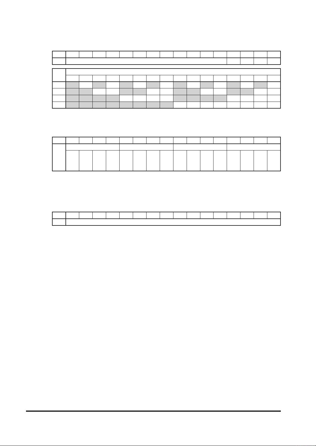
2) I/Ocontrolpoints
I/O control points are stored.
I/Ocontrolpoints
bit 15 14 13 12 11 10 9 8 7 6 5 4 3 2 1 0
K32 Unused (= 0) 3 2 1 0
Storage
place
512 480 448 416 384 352 320 288 256 224 192 160 128 96 64 32
bit 0 1 0 1 0 1 0 1 0 1 0 1 0 1 0 1 0
bit 1 1 1 0 0 1 1 0 0 1 1 0 0 1 1 0 0
bit 2 1 1 1 1 0 0 0 0 1 1 1 1 0 0 0 0
bit 3 1 1 1 1 1 1 1 1 0 0 0 0 0 0 0 0
I/O control points
3) I/O setting 0 to 3
I/O setting state of each address is stored.
I/O setting 0 to 3
bit 15 14 13 12 11 10 9 8 7 6 5 4 3 2 1 0
I/O setting 3 I/O setting 2 I/O setting 1 I/O setting 0
480
448
416
384
352
320
288
256
224
192
160
K33
to
511
to
479
to
447
to
415
to
383
to
351
to
319
to
287
to
255
to
223
to
191
128
to
159
(0: Input, 1: Output)
96
64
95
32
to
to
63
to
127
4) S-LINKVI/Ounitconnectednodes
Number of connected nodes of S-LINK V I/O units which are connected to S-LINK V system
are stored.
The storage value is from 0000 to 0100H (0 to 256).
NumberofconnectednodesofS-LINKVI/Ounits
bit 15 14 13 12 11 10 9 8 7 6 5 4 3 2 1 0
K34 Number of connected nodes of S-LINK V I/O units
0
to
31
9

5)S-LINKVsystemconnectedI/Ounitaddress
Connection states of
Bit corresponding to initial address of
S-LINK V systemconnectedI/Ounitaddress
bit 15 14 13 12 11 10 9 8 7 6 5 4 3 2 1 0
K35 15 14 13 12 11 10 9 8 7 6 5 4 3 2 1 0
K36 31 30 29 28 27 26 25 24 23 22 21 20 19 18 17 16
K37 47 46 45 44 43 42 41 40 39 38 37 36 35 34 33 32
K38 63 62 61 60 59 58 57 56 55 54 53 52 51 50 49 48
K39 79 78 77 76 75 74 73 72 71 70 69 68 67 66 65 64
K40 95 94 93 92 91 90 89 88 87 86 85 84 83 82 81 80
K41 111 11 0 109 108 107 106 105 104 103 102 101 100 99 98 97 96
K42 127 126 125 124 123 122 121 120 119 11 8 117 116 11 5 114 113 11 2
K43 143 142 141 140 139 138 137 136 135 134 133 132 131 130 129 128
K44 159 158 157 156 155 154 153 152 151 150 149 148 147 146 145 144
K45 175 174 173 172 171 170 169 168 167 166 165 164 163 162 161 160
K46 191 190 189 188 187 186 185 184 183 182 181 180 179 178 177 176
K47 207 206 205 204 203 202 201 200 199 198 197 196 195 194 193 192
K48 223 222 221 220 219 218 217 216 215 214 213 212 211 210 209 208
K49 239 238 237 236 235 234 233 232 231 230 229 228 227 226 225 224
K50 255 254 253 252 251 250 249 248 247 246 245 244 243 242 241 240
K51 271 270 269 268 267 266 265 264 263 262 261 260 259 258 257 256
K52 287 286 285 284 283 282 281 280 279 278 277 276 275 274 273 272
K53 303 302 301 300 299 298 297 296 295 294 293 292 291 290 289 288
K54 319 318 317 316 315 314 313 312 311 310 309 308 307 306 305 304
K55 335 334 333 332 331 330 329 328 327 326 325 324 323 322 321 320
K56 351 350 349 348 347 346 345 344 343 342 341 340 339 338 337 336
K57 367 366 365 364 363 362 361 360 359 358 357 356 355 354 353 352
K58 383 382 381 380 379 378 377 376 375 374 373 372 371 370 369 368
K59 399 398 397 396 395 394 393 392 391 390 389 388 387 386 385 384
K60 415 414 413 412 411 410 409 408 407 406 405 404 403 402 401 400
K61 431 430 429 428 427 426 425 424 423 422 421 420 419 418 417 416
K62 447 446 445 444 443 442 441 440 439 438 437 436 435 434 433 432
K63 463 462 461 460 459 458 457 456 455 454 453 452 451 450 449 448
K64 479 478 477 476 475 474 473 472 471 470 469 468 467 466 465 464
K65 495 494 493 492 491 490 489 488 487 486 485 484 483 482 481 480
K66 511 510 509 508 507 506 505 504 503 502 501 500 499 498 497 496
S-LINK V
I/O units which are memorized at system setting are stored.
S-LINK V
I/O unit will be set to “1.
S-LINK V
(1:
”
I/O unit is connected)
6) Number of nodes of error 3
Number of nodes of error 3 (error of recognized unit, disconnection or blown fuse) is stored.
Storage value is from 0000 to 0100H (0 to 256). In case error 3 does not occur or is eliminated, the past number of nodes of error 3 is stored (It is cleared when Y(n+1)A is turned ON).
Number of nodes of error 3
bit 15 14 13 12 11 10 9 8 7 6 5 4 3 2 1 0
K67 Number of nodes of error 3
10
 Loading...