

Page 1
Operating Instructions
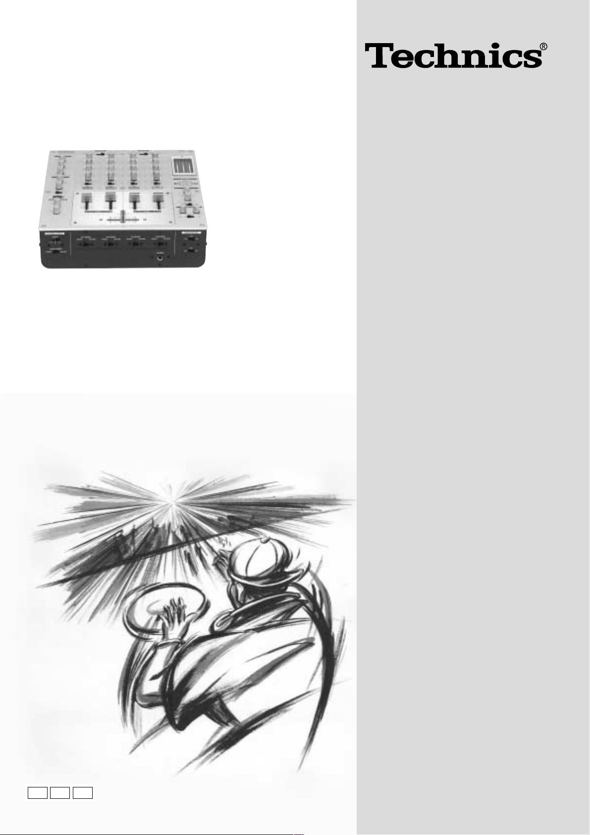
DJ Mixer
Model No.
The photograph shows the silver model.
SH-MZ1200
EB EP
GN
Note:
“EB” on the packaging indicates the United Kingdom.
Before connecting, operating or adjusting this product,
please read these instructions completely.
Please keep this manual for future reference.
RQT7231-B
Page 2

Dear customer
Supplied accessories
Thank you for purchasing this product.
For optimum performance and safety, please read these instructions
carefully.
Table of contents
Supplied accessories ................................................................... 2
Caution for AC Mains Lead ......................................................... 3
Safety precautions ....................................................................... 4
Main features ................................................................................ 4
Component part names ............................................................... 5
Connections .................................................................................. 7
Output side connections ............................................................ 7
Input side connections ............................................................... 8
Mixing (Basic operations) ........................................................... 9
Using the microphone .............................................................. 10
Recording and playing on external equipment ........................ 10
Additional mixing operations .................................................... 11
Adjusting the effect ................................................................... 11
Adjusting the monitor ................................................................ 11
Using play mode functions ....................................................... 12
Individually adjusting the left (L) and right (R) input ............... 12
Output separation (dual output separation) ............................ 12
Fader start function .................................................................... 13
Start using the channel fader ................................................... 13
Start using the cross fader ....................................................... 13
Block diagram ............................................................................. 14
Maintenance ................................................................................ 15
Troubleshooting guide............................................................... 15
Specifications ............................................................... Back page
Please check and identify the supplied
accessories.
For the United Kingdom only:
Use the numbers indicated in parentheses
when asking for replacements parts.
AC mains lead ........................... 1
F
or the United Kingdom (RJA0053-3X)
For Australia and New Zealand
(K2CJ2DA00008)
For others (RJA0019-2X)
Note
The included AC mains lead is for use with this unit only.
Do not use it with other equipment.
For United Kingdom and Republic of Ireland
www.panasonic.co.uk
(for UK customers only)
•
Order accessory and consumable items for your product with ease and confidence by telephoning
our Customer Care Centre Mon–Friday 9:00am–5:30pm.(Excluding public holidays.)
•
Or go on line through our Internet Accessory ordering application.
•
Most major credit and debit cards accepted.
•
All enquiries transactions and distribution facilities are provided directly by Panasonic UK Ltd.
•
It couldn’t be simpler!
Customer Care Centre
For UK customers: 08705 357357
For Republic of Ireland customers: 01 289 8333
Technical Support
For UK customers: 0870 1 505610
This Technical Support Hot Line number is for Panasonic PC software related products only.
For Republic of Ireland, please use the Customer Care Centre number listed above
for all enquiries.
For all other product related enquiries, please use the Customer Care Centre
numbers listed above.
2
RQT7231
Page 3
Caution for AC Mains Lead
Fuse
(5 ampere)
Fuse
(5 ampere)
Figure A
Figure B
CAUTION!
• DO NOT INSTALL OR PLACE THIS UNIT IN A
BOOKCASE, BUILT-IN CABINET OR IN ANOTHER
CONFINED SPACE. ENSURE THE UNIT IS WELL
VENTILATED. TO PREVENT RISK OF ELECTRIC SHOCK
OR FIRE HAZARD DUE TO OVERHEATING, ENSURE
THAT CURTAINS AND ANY OTHER MATERIALS DO
NOT OBSTRUCT THE VENTILATION VENTS.
•DO NOT OBSTRUCT THE UNIT’S VENTILATION
OPENINGS WITH NEWSPAPERS, TABLECLOTHS,
CURTAINS, AND SIMILAR ITEMS.
•DO NOT PLACE SOURCES OF NAKED FLAMES, SUCH
AS LIGHTED CANDLES, ON THE UNIT.
•DISPOSE OF BATTERIES IN AN ENVIRONMENTALLY
FRIENDLY MANNER.
WARNING:
TO REDUCE THE RISK OF FIRE, ELECTRIC SHOCK OR
PRODUCT DAMAGE, DO NOT EXPOSE THIS APPARATUS
TO RAIN, MOISTURE, DRIPPING OR SPLASHING AND
THAT NO OBJECTS FILLED WITH LIQUIDS, SUCH AS
VASES, SHALL BE PLACED ON THE APPARATUS.
This product may receive radio interference caused by
mobile telephones during use. If such interference is
apparent, please increase separation between the product
and the mobile telephone.
THIS UNIT IS INTENDED FOR USE IN MODERATE CLIMATES.
(For United Kingdom)
(“EB” area code model only)
For your safety, please read the following text carefully.
This appliance is supplied with a moulded three pin mains plug for
your safety and convenience.
A 5-ampere fuse is fitted in this plug.
Should the fuse need to be replaced please ensure that the
replacement fuse has a rating of 5-ampere and that it is approved
by ASTA or BSI to BS1362.
Check for the ASTA mark m or the BSI mark o on the body of the fuse.
If the plug contains a removable fuse cover you must ensure that it
is refitted when the fuse is replaced.
If you lose the fuse cover the plug must not be used until a
replacement cover is obtained.
A replacement fuse cover can be purchased from your local dealer.
CAUTION!
IF THE FITTED MOULDED PLUG IS UNSUITABLE FOR
THE SOCKET OUTLET IN YOUR HOME THEN THE FUSE
SHOULD BE REMOVED AND THE PLUG CUT OFF AND
DISPOSED OF SAFELY.
THERE IS A DANGER OF SEVERE ELECTRICAL SHOCK
IF THE CUT OFF PLUG IS INSERTED INTO ANY 13AMPERE SOCKET.
If a new plug is to be fitted please observe the wiring code as
stated below.
If in any doubt please consult a qualified electrician.
The socket outlet shall be installed near the equipment and
easily accessible or the mains plug or an appliance coupler
shall remain readily operable.
Although the AC power switch is in the “OFF” position, the
unit is not completely disconnected from the mains. Remove
the plug from the main electrical outlet if you will not be
using the unit for an extended period of time. Place the unit
so the plug can be easily removed.
IMPORTANT
The wires in this mains lead are coloured in accordance with the
following code:
Blue: Neutral, Brown: Live.
As these colours may not correspond with the coloured markings
identifying the terminals in your plug, proceed as follows:
The wire which is coloured Blue must be connected to the terminal
which is marked with the letter N or coloured Black or Blue.
The wire which is coloured Brown must be connected to the terminal
which is marked with the letter L or coloured Brown or Red.
WARNING: DO NOT CONNECT EITHER WIRE TO THE
EARTH TERMINAL WHICH IS MARKED WITH THE
LETTER E, BY THE EARTH SYMBOL
nn
n OR COLOURED
nn
GREEN OR GREEN/YELLOW.
THIS PLUG IS NOT WATERPROOF—KEEP DRY.
Before use
Remove the connector cover.
How to replace the fuse
The location of the fuse differ according to the type of AC mains
plug (figures A and B). Confirm the AC mains plug fitted and follow
the instructions below.
Illustrations may differ from actual AC mains plug.
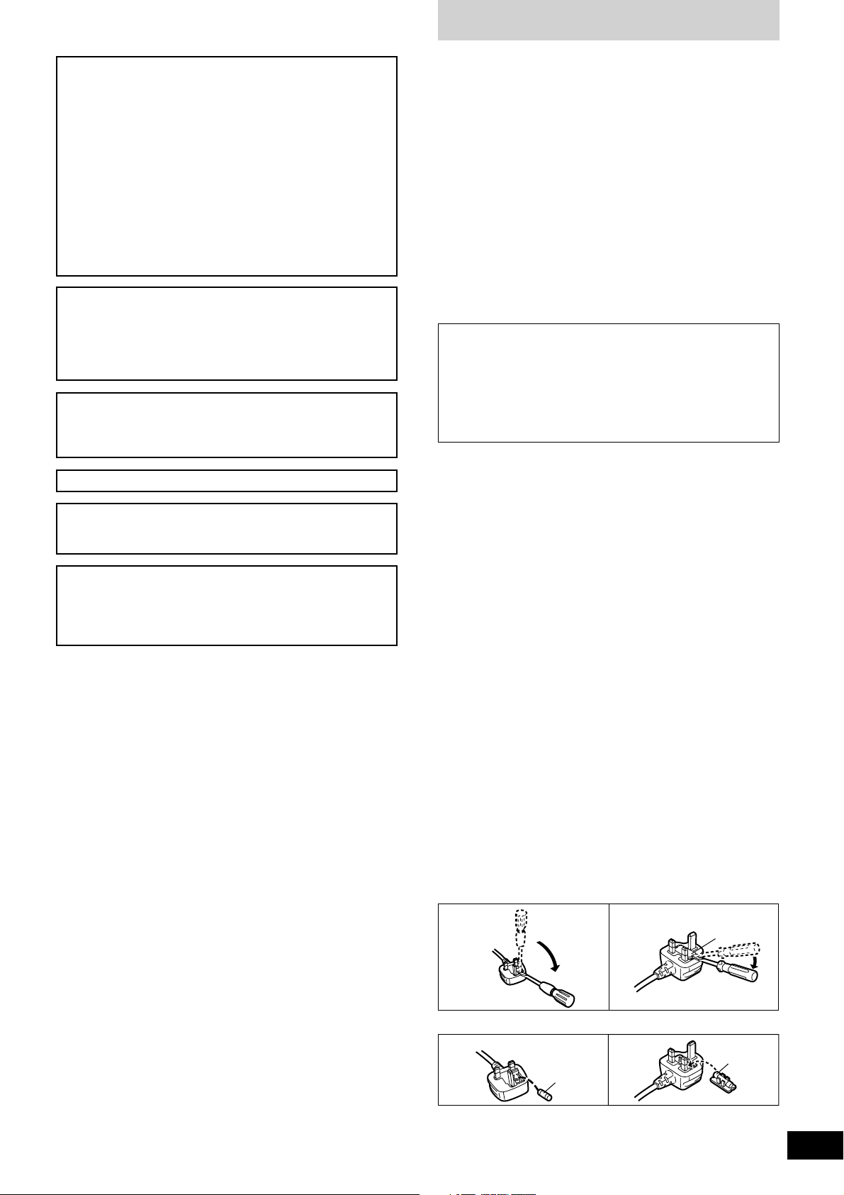
1. Open the fuse cover with a screwdriver.
Figure A
Figure B
Fuse cover
2. Replace the fuse and close or attach the fuse cover.
3
RQT7231
Page 4

Safety precautions
Main features
Placement
Set the unit up on an even surface away from direct sunlight, high
temperatures, high humidity, and excessive vibration. These conditions
can damage the cabinet and other components, thereby shortening
the unit’s service life.
Do not place heavy items on the unit.
Voltage
Do not use high voltage power sources. This can overload the
unit and cause a fire.
Do not use a DC power source. Check the source carefully when
setting the unit up on a ship or other place where DC is used.
AC mains lead protection
Ensure the AC mains lead is connected correctly and not damaged.
Poor connection and lead damage can cause fire or electric shock.
Do not pull, bend, or place heavy items on the lead.
Grasp the plug firmly when unplugging the lead. Pulling the AC
mains lead can cause electric shock.
Do not handle the plug with wet hands. This can cause electric
shock.
Foreign matter
Do not let metal objects fall inside the unit. This can cause electric
shock or malfunction.
Do not let liquids get into the unit. This can cause electric shock
or malfunction. If this occurs, immediately disconnect the unit from
the power supply and contact your dealer.
Do not spray insecticides onto or into the unit. They contain
flammable gases which can ignite if sprayed into the unit.
Service
Do not attempt to repair this unit by yourself. If sound is interrupted,
indicators fail to light, smoke appears, or any other problem that is not
covered in these operating instructions occurs, disconnect the AC
mains lead and contact your dealer or an authorized service center.
Electric shock or damage to the unit can occur if the unit is repaired,
disassembled or reconstructed by unqualified persons.
Extend operating life by disconnecting the unit from the power
source if it is not to be used for a long time.
Insertion of connector
Even when the connector is perfectly inserted, depending on the
type of inlet used, the front part of
the connector may jut out as shown
in the drawing.
However there is no problem using
the unit.
Approx. 6 mm
Appliance inlet
Connector
A 4 channel universal type DJ oriented DJ mixer providing new audio
performance and functional with the Technics SL-DZ1200 direct drive
digital turntable (Not included) hereinafter referred to as the digital
turntable.
Robust basic functions
Input-output features
•12 input terminals are available, 2 for CD/LINE input, 3 for LINE
input, 3 for PHONO input, 2 for microphone input and 2 for digital
input.
•Digital output, audio recording output, monitor output, headphone
output, master 1 and 2 output, and a pro-spec engineered XLR
terminal which all function independently.
•An EFFECT SEND, EFFECT RETURN terminals have also been
added for use with an external effector.
3 Band equalizer for sound-source level
•A HIGH, MID, LOW equalizer is provided for each channel. A wide
variety of possibilities are provided for sound as the attenuation
range is set to a high -24 dB (12 dB/oct).
Robust monitor features for play
•Monitoring of the desired channel can be done quickly now that a
CUE button has been added to each channel and to the effect
function.
•Using the MONITOR MIXING control knob you can mix the master
output and the channel selected with the CUE button. Using MONO
SPLIT MODE, you can monitor master output and the selected
channel split separately into the left and right channels.
Support for an external effector
•You can turn EFFECT on and off for each channel. Select PRE or
POST connection for the effector and adjust the SEND, RETURN
level control.
Digitally controlled fader components that are robust and
functional
•A C. FADER CURVE switch has been added to the cross fader to
provide 3 new types of cross fader curve settings.
•A reverse switch has been added for each channel fader and the
cross fader.
•Through the use of an engineered VCA control, volume can be
controlled with very little loss in audio quality using the channel
fader or cross fader.
•Reliability improvements have been made to the cross fader through
the adoption of optical cross fader circuits and a highly durable 45
mm stroke fader providing smooth operation.
Providing new audio performance using the channel
fader and cross fader
Use the channel fader to control the left (L) and right (R) channels
individually
•With the PLAY MODE function the selected channels can be
separated and the L or R volume can be controlled individually
using the channel fader.
Control the FRONT and REAR output for two channel output using
master 1, 2
•By turning the SEPARATE OUT switch to on, you can separate CH1
and CH2 output to the front and CH3 and CH4 output to the rear,
providing you with new sound field performance in combination with
the feature of being able to adjust the left (L) and right (R) channels
individually.
Linked play on the connected digital turntable
Real-time start and stop control using the fader
•You start and stop the digital turntable by operating the channel
fader or cross fader when connected to a digital turntable with a
control cable.
•A maximum of 2 digital turntables can be linked digitally through 2
digital inputs.
4
RQT7231
Page 5
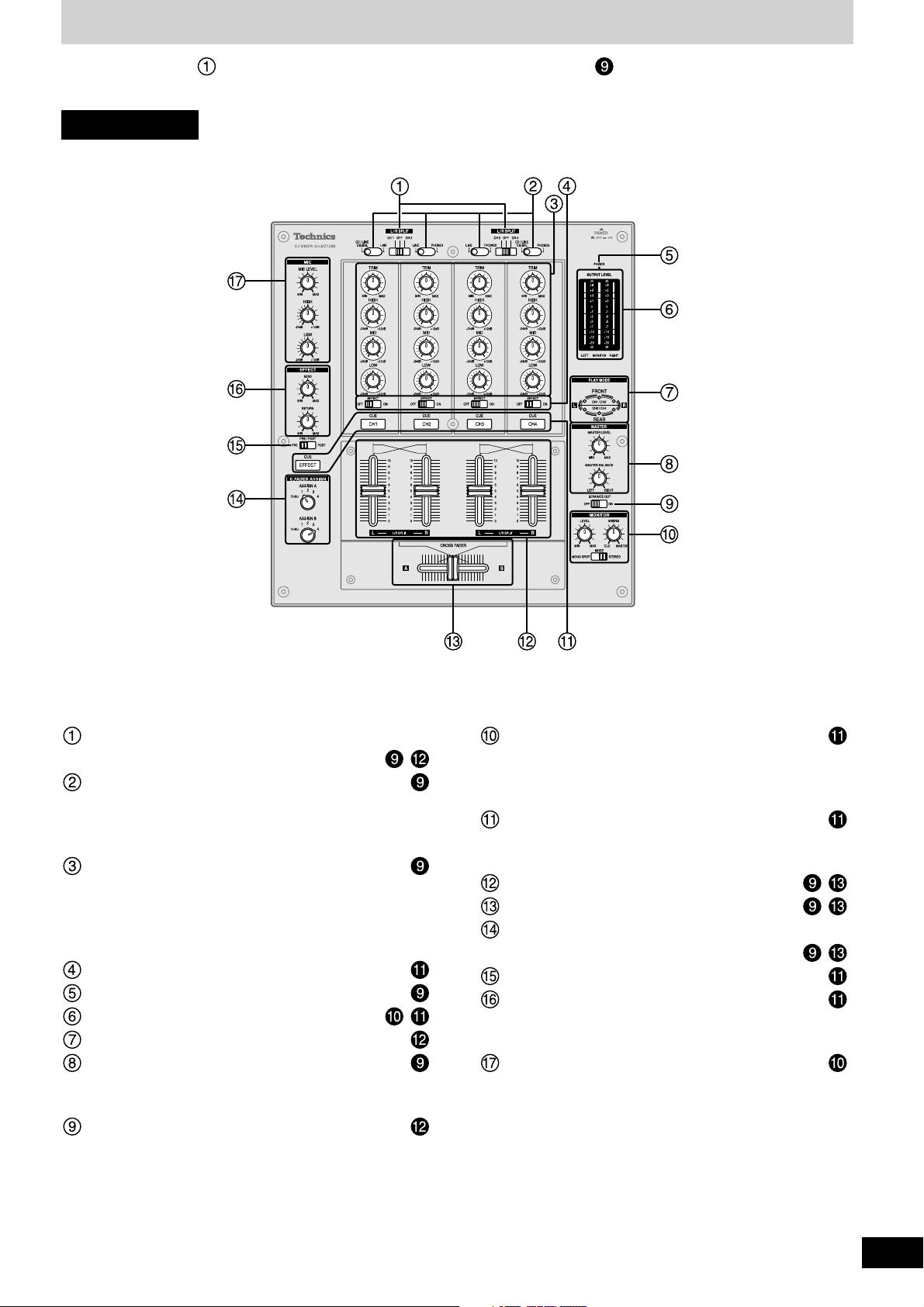
Component part names
The unshaded numbers etc, correspond to the numbered illustrations. The shaded numbers etc, are reference pages.
Control panel
Input switch for adjusting left and right input
individually (L/R SPLIT) ...................................
Input switch (CH1-CH4) ..........................................
CD/LINE DIGITAL: Line or CD input, Digital input
LINE: Line input
PHONO 1-3: Turntable phono input
Input control knob (CH1-CH4) ...............................
Input level control knob (TRIM)
High-tone input control knob (HIGH)
Mid-tone input control knob (MID)
Low-tone input control knob (LOW)
Channel effect (CH1-CH4) switch (EFFECT) ........
Power indicator lamp (POWER) ............................
Output level meter (OUTPUT LEVEL) ............ ,
Play mode lamp (PLAY MODE) ..............................
Master output control knob (MASTER) .................
Master level volume control knob (MASTER LEVEL)
Master balance control knob (MASTER BALANCE)
Output separation ON, OFF switch (SEPARATE OUT)
Monitor control knob (MONITOR)..........................
,
Monitor level volume control knob (LEVEL)
Monitor mixing control knob (MIXING)
Monitor mode switch (MODE)
Monitor select button-display lamp (CUE) ...........
CH1-CH4: CH1-CH4 monitor selector
EFFECT: Effector monitor selector
Channel fader (CH1 - CH4) .............................. ,
Cross fader (CROSS FADER) ......................... ,
Cross fader Assign A, B switch
(C. FADER ASSIGN) .........................................
Effector output switch (PRE/POST) ......................
Input-output effect control knob (EFFECT) ..........
Output effect control knob (SEND)
Input effect control knob (RETURN)
Microphone input control knob (MIC) ...................
Microphone level volume control knob (MIC LEVEL)
High-tone microphone control knob (HIGH)
Low-tone microphone control knob (LOW)
,
5
RQT7231
Page 6
Component part names
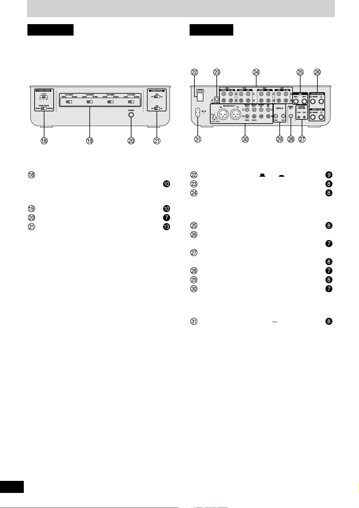
Front panel Rear panel
Cross fader curve control switch
(C.FADER CURVE) ..................................................
Curve switch (CURVE)
Cross fader operation switch (CROSS FADER)
Fader operation switch (CH1-CH4 FADER) ..........
Headphone terminal (PHONES) .............................
Fader start (ON, OFF) switch (FADER START) .....
Power button (POWER OFF ON) ...................
Turntable earth terminal (PHONO EARTH) ...........
Input terminal (CH1-CH4) .......................................
CD/LINE: CD or line terminal
LINE: Line terminal
PHONO 1-3: Turntable phono terminal
Microphone input terminal (MIC1, MIC2) ..............
Effector input-output terminal
(EFFECT RETURN, EFFECT SEND) ......................
Player control (CH1, CH4) terminal
(PLAYER CONTROL) ..............................................
Digital output terminal (DIGITAL OUT) ..................
Digital input (CH1, CH4) terminal (DIGITAL IN) ....
Output terminal .......................................................
Master out 1, 2 terminal (MASTER OUT)
Monitor out terminal (MONITOR OUT)
Rec terminal (REC OUT)
Power input terminal (AC IN ) ............................
6
RQT7231
Page 7
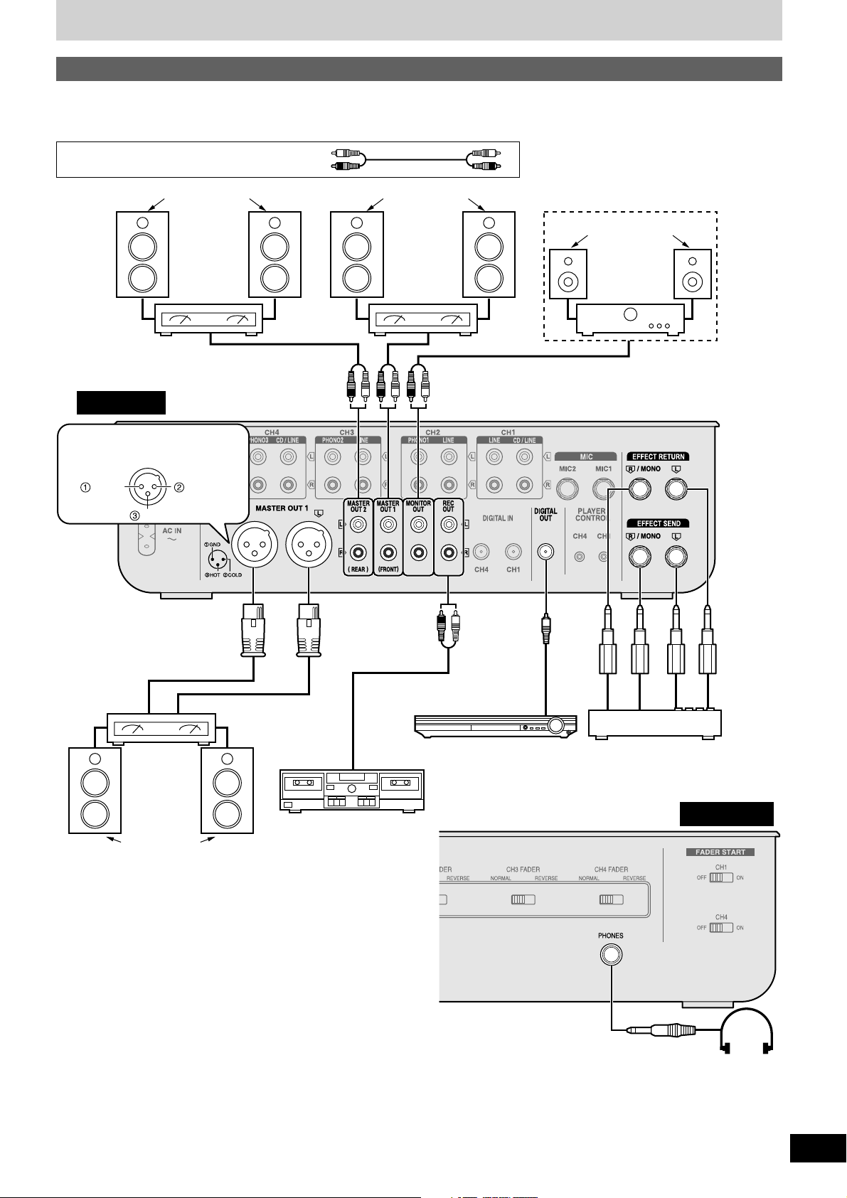
Connections
Output side connections
Connect the various equipment to the DJ mixer using stereo phono cables, connection cables and appropriate cables (Each sold separately).
When connecting, make sure to turn all equipment power off.
Stereo phono cables
Speakers
(Not included)
Amplifier
(Not included)
Rear panel
Connect when using an amplifier that
has XLR terminals. Terminal polarity is
indicated in the diagram below.
Cold (–)Ground
Hot (+)
White (L)
Red (R)
Speakers
(Not included)
Amplifier
(Not included)
Speakers
(Not included)
Monitor amplifier
(Not included)
Connection
cable
(Not included)
Type:
RCA coaxial
Amplifier
(Not included)
(XLR terminal
compatible)
Speakers
(Not included)
Cassette deck (Not included)
AV Control Receiver
(Not included)
Effector (Not included)
Connect if you want to use an
external effector or sampler etc.
to adjust the sound.
Type:
6.3 mm stereo
When using a monaural input effector
•Connect to the R/MONO terminal.
•The mixed left (L) and right (R) signal is output to the effector, and the left (L) and right (R) signal from the effector is input.
Type:
6.3 mm
monaural
Front panel
Headphone
(Not included)
When listening with headphones
•Turn down the volume using the MONITOR LEVEL control knob before connecting.
•Avoid listening for prolonged periods of time to prevent hearing damage.
7
RQT7231
Page 8

Connections
Connect for use with
the fader start function
( page 13)
Input side connections
Connect the DJ mixer and various equipment with stereo phono cables,
control cables and connection cables (Each sold separately).
Connect the AC mains lead after completing all the other
connections.
Direct drive digital turntable 2
(Not included)
Control cable
(Not included)
Type: 3.5 mm
stereo
CD player 2 (Not included)
Rear panel
Connection to the SH-MZ1200 rear panel PLAYER
CONTROL terminal
Only the separately sold direct drive digital turntable can be
operated.
Connecting to control terminals of other manufacturer’s products
may result in incorrect operation or other equipment problems.
Direct drive digital turntable 1
CD player 1 (Not included)
Control cable
(Not included)
Type: 3.5 mm
stereo
Type:
6.3 mm monaural
(Not included)
Microphone 2
(Not included)
Microphone 1
(Not included)
For the United Kingdom:
BE SURE TO READ THE CAUTION FOR THE AC MAINS LEAD ON PAGE 3 BEFORE CONNECTION.
Note
It is not necessary to connect a grounding wire if there is no grounding terminal or grounding wire on the turntable.
8
RQT7231
AC mains lead
(Included)
Connection cable (Not included)
Type: RCA coaxial
Household
mains socket
Grounding
wire
Turntable 3 (Not included) Turntable 2 (Not included) Turntable 1 (Not included)
Connection cable (Not included)
Type: RCA coaxial
Direct drive digital turntable
(Not included)
Direct drive digital turntable
(Not included)
Cassette deck (Not included)
Page 9

Mixing (Basic operations)
L/R SPLIT
LR
5 Use the channel fader to adjust the
volume
Select the CH2-CH4 source and adjust
volume and sound
(Same as instructions 3 - 5 indicated on the left)
6 When using the cross fader
Turn [ASSIGN A] and [ASSIGN B] to
select the input channel to assign
and
•Select different input channels using the ASSIGN A and
ASSIGN B switches.
If the same input channel is selected by both switches, the
volume will remain unchanged even when the cross fader is
operated.
•The channel selected with ASSIGN A is assigned to , the
channel selected with ASSIGN B is assigned to .
Unassigned channels are not output through the cross fader.
1-4: Assigned channels 1 to 4
THRU: When not using the cross fader
7 When using the cross fader
Use [CROSS FADER] to adjust the
mixing level
The mixing level of the source audio assigned to and is
adjusted by varying the position of the cross fader.
Press [POWER OFF ON]
The POWER lamp comes on after the power is turned on.
1 Turn [L/R SPLIT (CH1 CH2)] and [L/R
SPLIT (CH3 CH4)] to OFF
Select CH1 or CH2 input, CH3 or CH4 input to use the PLAY
MODE's (L) and (R) individual adjustment feature ( page 12).
2 Switch [SEPARATE OUT] to OFF
Turn on to activate the play mode SEPARATE OUT function
( page 12).
Using CH1 input
3 Switch the input switch (CD/LINE
DIGITAL, LINE) to select the source
When you select CD/LINE DIGITAL on CH1 or CH4, input can
be analogue input (CD/LINE CH1, CH4 input terminal) or digital
input (DIGITAL IN CH1, CH4 input terminal).
4 Turn [TRIM], [HIGH], [MID] and [LOW]
to adjust the input signal level and
sound
TRIM:
Adjusts the input signal level.
Turn to the right for higher sound level (to approximately +8 dB)
Turn to the left for lower sound level (to approximately –8 dB)
HIGH:
Adjusts the high tone input sounds. Sound is flat at the center
position.
Turn to the right to increase sound (to approximately +12 dB at 10 kHz)
Turn to the left to decrease sound (to approximately –24 dB at 10 kHz)
MID:
Adjusts the mid tone input sounds. Sound is flat at the center
position.
Turn to the right to increase sound (to approximately +12 dB at 1 kHz)
Turn to the left to decrease sound (to approximately –24 dB at 1 kHz)
LOW:
Adjusts the low tone input sounds. Sound is flat at the center
position.
Turn to the right to increase sound (to approximately +12 dB at 50 Hz)
Turn to the left to decrease sound (to approximately –24 dB at 50 Hz)
8 Turn [MASTER LEVEL] and [MASTER
BALANCE] to adjust the volume and
balance
Adjust the master output volume and left (L) and
right (R) balance.
•Input source audio from the selected channels CH1-CH4 is
mixed and output through the MASTER OUT 1 left (L) and
(R) terminals.
•Even if the MASTER LEVEL or the MASTER BALANCE is
changed the REC OUT or DIGITAL OUT output does not
change.
9
RQT7231
Page 10

Mixing (Basic operations)
Using the microphone
OUTPUT
LEVEL
meter
Changing the channel fader, cross fader operation
method
Use the channel fader switch to change the operation method for each
channel.
(e.g. using CH1) Switch [CH1 FADER] and [CROSS FADER]
NORMAL: Operation is as indicated on the panel
REVERSE: Operation is reverse as indicated on the panel
Changing the cross fader curve
Select from 1 of 3 types of cross fader startup curves.
Switch [CURVE]
Output level meter display
•The mixed left (L) and right (R) volume level of the selected channel
(CH1-CH4) is displayed in the LEFT and RIGHT columns of the
output level meter.
Display range: –20 to +8 dB
•Even if the MASTER LEVEL or MASTER BALANCE is changed
the OUTPUT LEVEL meter display does not change.
Turn [MIC LEVEL], [HIGH] and [LOW] to
adjust volume and sound
Adjusts the microphone volume and sound connected
to MIC 1 and MIC 2 terminals.
MIC LEVEL:
Adjusts the microphone volume (Attenuation: – ∞ to 0 dB)
HIGH:
Adjusts the high tone microphone sound. Sound is flat at the center
position.
Turn to the right to increase (to approximately +12 dB at 10 kHz)
Turn to the left to decrease (to approximately –24 dB at 10 kHz)
LOW:
Adjusts the low tone microphone sound. Sound is flat at the center
position.
Turn to the right to increase (to approximately +12 dB at 100 Hz)
Turn to the left to decrease (to approximately –24 dB at 100 Hz)
•Input of MIC 1 and MIC 2 is mixed and output through the MASTER
OUT 1 left (L) and right (R) terminals.
Recording and playing on external
equipment
You can record and play on externally
connected equipment.
Using the REC OUT terminal
The same source as MASTER OUT 1 is output.
Using the DIGITAL OUT terminal
The same digital signal source as MASTER OUT 1 is output.
Even if the MASTER LEVEL or the MASTER BALANCE is changed
the REC OUT or DIGITAL OUT output does not change and recording
or play remains unaffected.
Note
The channel fader and cross fader used with this unit are designed
for extended use however, depending on the way they are being used
(e.g. quick, repetitive movements such as Hip Hop transfer play,etc.)
replacement may be necessary.
•Contact your nearest dealer to have your channel fader and or
cross fader replaced.
•To the dealer:
The “Fader Replacement Instructions” are included with the
replacement product.
Replacement part number
Channel fader (Part No. REP3743A-S)
Cross fader (Part No. REP3742A-S)
10
RQT7231
Page 11

Additional mixing operations
Adjusting the monitor
OUTPUT
LEVEL
meter
Adjusting the effect
You can adjust the volume level and select the output point when
using an externally connected effector.
On the channel you have selected to use
effect output
1 Switch [EFFECT] to ON
Outputs to the external effector.
2 Switch [PRE/POST] and select the
output point
PRE: Outputs before the channel fader
POST: Outputs after the channel fader
3 Turn [SEND] to adjust the output level
Adjusts the output volume level sent to the external
effector.
4 Turn [RETURN] to adjust the input level
Adjusts the input volume level from the external
effector.
•An effect is applied to the input source sound and output to
the MASTER OUT 1 terminal.
Using output separation
When using output separation (dual output separation) ( page 12),
audio is output through the MASTER OUT 2 (REAR) terminal.
You can check the sound on the headphones etc. during play and cue
the channel you want to mix, and adjust the volume and check the
mixing sound.
Monitoring CH1
1 Press [CUE CH1] to turn on the monitor
sound
•The display lamp lights once the CUE button is pressed.
•Monitor sound from the selected channel is output to
PHONES (Headphones) and MONITOR OUT terminal.
•Mixed sound can be output by pressing multiple CUE buttons.
When using an effector ( left side of this page)
Press [CUE EFFECT] to turn on the
monitor sound
•Monitor EFFECT RETURN is output.
2 Select the input, adjust the input level,
sound, and adjust the volume with the
channel fader and cross fader
( page 9, Mixing, instructions 3 - 7)
3 Turn [MIXING] and adjust mixing
•Turn completely to the right for audio from the master output.
•Turn completely to the left for audio from the channel selected
with the CUE button.
•When the control knob is in the center position the audio
level of the master output and the channel selected with the
CUE button is half and half.
•The monitor volume level is displayed in the MONITOR
column of the output level meter.
4 Switch [MODE] and select the monitor
sound
You can select the monitor sound to be stereo or
split between the channel selected with CUE button
(L) and master (R).
Select MONO SPLIT and the monitor output will become
monaural, left (L) will output audio from the channel selected
with the CUE button, and the right (R) will output audio from
the master output channel.
5 Turn [LEVEL] to adjust the monitor
volume
•Even if the MASTER LEVEL and MASTER BALANCE is
changed the monitor sound does not change.
11
RQT7231
Page 12

Using play mode functions
Output separation
(dual output separation)
By turning the SEPARATE OUT function ON, you can output audio
through 2 separate channels, from MASTER OUT 1 (FRONT) and
from MASTER OUT 2 (REAR). You can adjust the left and right output
individually and use the cross fader for real time play.
PLAY MODE
lamp
Individually adjusting the left (L) and
right (R) input
Using the play mode function, by separating the left (L) and right (R)
selected input channel you can individually adjust the left (L) and right
(R) volume and sound.
1 Switch to either [L/R SPLIT (CH1 CH2)]
or [L/R SPLIT (CH3 CH4)] and select the
channel to adjust individually
The input of the selected channel is allocated to
the channel to be adjusted on the panel.
CH1 or CH2 input: Left (L) is input to CH1 on the panel, right
CH3 or CH4 input: Left (L) is input to CH3 on the panel, right
•The L or R PLAY MODE lamp of the selected channel lights.
•By selecting OFF, input becomes both channels without any
separation. The L or R PLAY MODE lamp doesn’t light.
(R) is input to CH2 on the panel.
(R) is input to CH4 on the panel.
(e.g.) MASTER OUT 1 (FRONT)
terminal:
For the front speaker
MASTER OUT 2 (REAR)
terminal:
For the rear speaker
[MASTER OUT 1]
L R
Venue
[MASTER OUT 2]
LR
Turn [SEPARATE OUT] ON
•CH1 and CH2 input is output from the MASTER OUT 1
(FRONT) and MASTER OUT 1 (XLR) terminal.
•CH3 and CH4 input is output from the MASTER OUT 2
(REAR) terminal.
•The FRONT and REAR PLAY MODE lamps light.
Using the cross fader
From Mixing on page 9, perform instructions 6-7.
While the cross fader is in NORMAL position
While ASSIGN A : 1 or 2, ASSIGN B : 3 or 4
When the cross fader is moved all the way toward :
Only the source audio assigned to is output from the MASTER
OUT 1 (FRONT) and MASTER OUT 1 (XLR) left (L) and right (R)
terminals.
When the cross fader is moved all the way toward :
Only the source audio assigned to is output from the MASTER
OUT 2 (REAR) left (L) and right (R) terminals.
When the cross fader is in the center position:
Source audio assigned to is output through the MASTER OUT 1
(FRONT) and MASTER OUT 1 (XLR) terminals, and source audio
assigned to is output through the MASTER OUT 2 (REAR) terminal.
Adjusting the input level and sound, and using the
channel fader to adjust the volume
From Mixing on page 9, perform instructions 4-5.
2 Adjusting left (L) and right (R) input
level and sound, and use the channel
fader to adjust the volume
( page 9, Mixing, instructions 4 - 5)
Adjusting the CH1 or CH2 level, sound, channel fader
Left (L) input: Use any of the CH1 knobs on the panel
Right (R) input: Use any of the CH2 knobs on the panel
Adjusting the CH3 or CH4 level, sound, channel fader
Left (L) input: Use any of the CH3 knobs on the panel
Right (R) input: Use any of the CH4 knobs on the panel
•Mixed source audio is output from the left (L) and right (R)
terminals of MASTER OUT 1.
Using the cross fader
From Mixing on page 9, perform instructions 6-7.
Select the same channel selected above in instruction 1 for
switching ASSIGN A and ASSIGN B.
Adjusting the master output volume and balance
From Mixing on page 9, perform instruction 8.
Adjusting the master output volume and balance
From Mixing on page 9, perform instruction 8.
Adjust the volume and left (L) and the right (R) balance of the MASTER
OUT 1 (FRONT), MASTER OUT 1 (XLR) and MASTER OUT 2 (REAR)
output.
Adjusting individually of left (L) and right (R) input
Perform instructions 1-2 on the left.
12
RQT7231
Page 13

Fader start function
You can start music play from the SL-DZ1200 direct drive digital turntable (not included) using the channel fader and cross fader by connecting the
digital turntables to CH1 and CH4. (A control cable is necessary for this connection.
page 8)
Start using the cross fader
When the digital turntable you want to control is connected to CH1
and the cross fader operation switch is set to NORMAL.
1 Turn [ASSIGN A] and select 1
2 Push [CROSS FADER] all the way in the
direction opposite the source you want
to start ( )
3 Switch [FADER START (CH1)] to ON
4 Slide [CROSS FADER] in the direction
opposite of instruction 2 when you want
to start play
•Play instantly begins from the digital turntable.
If you push the cross fader back to the original position after play on
the digital turntable has started, the digital turntable returns to the set
point and waits in the standby position.
Before use
•Turn [MODE] to TURNTABLE on the rear panel of the digital
turntables connected to CH1 and CH4.
•Set the auto cue point and cue point on the digital turntables
connected to CH1 and CH4, and standby at the set point.
Start using the channel fader
When the digital turntable you want to control is connected to CH1
and the channel fader operation switch is set to NORMAL.
•When individually adjusting the left (L) and right (R) input ( page
12), perform the following instructions simultaneously for the CH1
and CH2 channel faders on the panel.
1 Turn [ASSIGN A] and select any number
other than 1
•The channel fader will not start the digital turntable if 1 is
selected.
2 Push the channel fader all the way to
zero
3 Switch [FADER START (CH1)] to ON
4 Push the channel fader up when you
want to start play
•Play instantly begins from the digital turntable.
Alternate play of two digital turntables connected to CH1
and CH4
When the cross fader operation switch is set to NORMAL.
1 Turn [ASSIGN A] to select 1 and turn
[ASSIGN B] to select 4
2 Push [CROSS FADER] all the way in the
direction opposite the source you want
to start ( )
3 Switch [FADER START (CH1)] and
[FADER START (CH4)] to ON
4 Push [CROSS FADER] all the way in the
direction opposite of instruction 2
(towards ), when you want to start
play
•Play instantly begins from the digital turntable connected to
CH1. (At the same time, the digital turntable returns to the
set point when playing on CH4)
5 Push [CROSS FADER] all the way in the
direction opposite of instruction 4
(towards )
•Play instantly begins from digital turntable on CH4.
•Play on CH1 instantly returns to the set point.
If you push the channel fader back to the original position (zero) after
play on the digital turntable has started, the digital turntable returns to
the set point and waits in the standby position.
Note
While you are using the fader to start play, turning the unit off and on
may stop or start the digital turntable.
13
RQT7231
Page 14

Block diagram
CH FADER
CH1-CH4
MONITOR
LEVEL
RETURN
CUE
ON/OFF
CD/LINE
LINE PHONO
CH1-CH4
EFFECT PRE/POST
MASTER BAL.
MASTER
OUT 1 (XLR)
(BAL.OUT)
MASTER
OUT 2
(REAR)
MASTER
OUT 1
(FRONT)
REC OUT
DIGITAL
OUT
MASTER LEVEL
C.FADER
NORMAL/REV.
CROSS FADER
NORMAL/REV.
CH1-CH4
C.FADER
CURVE TYPE
PHONO EQ
LINE
LINE
CD/LINE
PHONO 1
DIGITAL
IN
CH1
DIGITAL
IN
CH4
CH2
CH3
CH1
TRIM
CH1-CH4
DAI
Receiver
DAC
HIGH/
MID/LOW
CH1-CH4
L/R
SPLIT
ON/OFF
L/R
SPLIT
ON/OFF
EFFECT
RETURN
MIC1
MIC2
MIC LEVEL
ANALOG SWITCH
ANALOG SWITCH
EFFECT MIX
CHANGE
PHASE
Master-Lch/
Cue-mix
Cue-Rch/
Master-mix
Cue-Lch
Master-Rch
EFFECT
SEND
PLAYER
CONTROL
BAL. AMP
MICRO
COMPUTER
EFFECT POST
CH1
CUE MIX
MASTER MIX
L ch
R ch
CH4
L
R/MONO
CH1
L ch
R ch
SEND
OUTPUT LEVEL METER
MONITOR
OUT
PHONES
R IN
OFF
ON
Pulse trans.
L IN
MONITOR IN
SEPARATE OUT ON:
MASTER OUT1: CH1/CH2
MASTER OUT2: CH3/CH4
SEPARATE OUT OFF:
MASTER OUT1: CH1/CH2/CH3/CH4
MASTER OUT2: NO OUTPUT
PHONO EQ
PHONO EQ
LINE
PHONO 2
PHONO 3
CD/LINE
CH4
L
R/MONO
MIC AMP
EFFECT PRE
CH4
CH3
CH2
CH2
CH1
LOW
HIGH
MIC EQ
L/R PLAY
MODE ASSIGN
C.FADER
ASSIGN A/B
V.C .A
AMP
V.C .A
AMP
V.C .A
AMP
V.C .A
AMP
CH3
CH4
DAI Trans.
MONO SPLIT
MIX LEVEL
MONITOR MIX
STEREO
ADC
L ch
R ch
FRONT
MIXER
REAR
MIXER
ONOFF
FADER START
CH1,CH4
EFFECT ON/OFF
SEPARATE
OUT
ON/OFF
CHANGE
PHASE (EFFECT)
DAI
Receiver
DAC
14
RQT7231
Page 15
Maintenance
To clean this unit, wipe with a soft, dry cloth.
•Never use alcohol, paint thinner, or benzine to clean this unit.
•Before using chemically treated cloth, read the instructions that came with the cloth carefully.
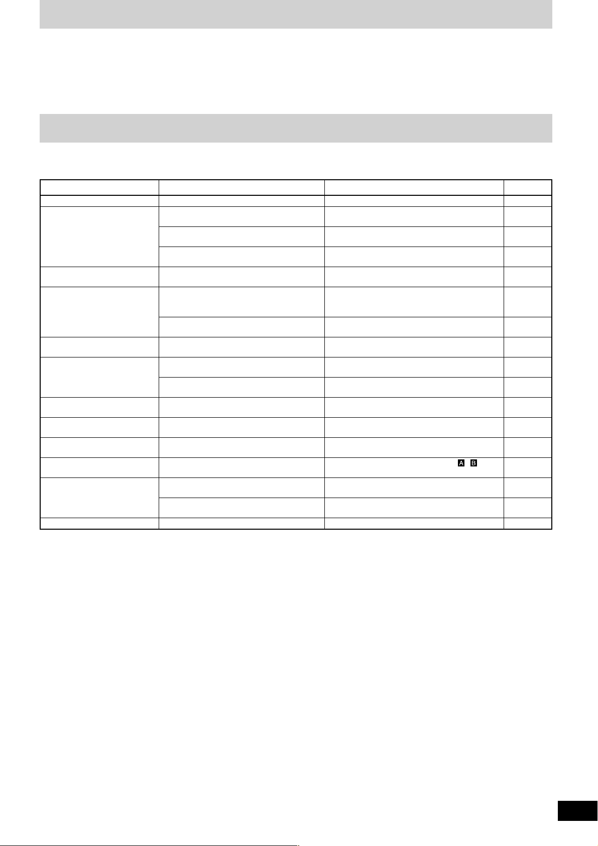
Troubleshooting guide
Before requesting service, make the below checks. If you are in doubt about some of the check points, or if the remedies indicated in the
chart do not solve the problem, consult your dealer for instructions.
Problem
No power.
No sound even when the
power is on.
The volume is low.
Left and right sound is
reversed.
Low hum or buzz is heard
during play.
Fader (control slider) does
not move smoothly.
Sound is distorted.
External effector's sound is
distorted.
Effect does not appear to be
working.
Fader operation is reversed.
Cannot use the cross fader.
Cannot start the digital
turntable with the fader.
Output is not separated.
Check
Has the power plug been disconnected?
Has the input switch been set to another
source?
Have any of the units been wrongly
connected?
Is the master level control or other volume
level controls at the MIN position?
Have you connected with the left and right
terminals reversed?
Is there a fluorescent light or other electrical
appliances, or are their power cables near
any of the connecting cables?
Has the turntable’s grounding wire been
disconnected?
Is one of the faders worn out?
Is the master volume level or monitor volume
level too high?
Is the input level too high?
Is the input level from the external effector
too high?
Is the EFFECT switch OFF?
Is the fader operation switch in the
REVERSE position?
Are the ASSIGN A and ASSIGN B switch
settings wrong?
Is the FADER START switch OFF?
Are the digital turntable and mixer connected
using a control cable?
Is the SEPARATE OUT switch OFF?
Action
Connect the power plug securely.
Check the source and set the control to the
proper position.
Connect the units properly.
Adjust the volume level controls correctly.
Connect the channels correctly.
Place the fluorescent light, other appliances or
their power cables as far away from the unit as
possible.
Connect the grounding wire securely.
Replace with a new fader.
Contact your nearest dealer.
Adjust the MASTER LEVEL or MONITOR LEVEL
control knobs.
Reduce the level by turning the TRIM control
knob.
Reduce the external effector's output level by
adjusting the SEND or RETURN control knob.
Turn the EFFECT switch ON for the channel to
be used.
Turn switch to the NORMAL position.
Select the input source assigned to , .
Turn ON the FADER START switch for the
channel to be used.
Use a control cable to connect the digital turntable
to the mixer.
Switch the SEPARATE OUT switch to ON.
Page Reference
8
9
7 - 8
9 - 10
7 - 8
—
8
10
9, 11
9
11
11
10
9
13
8
12
15
RQT7231
Page 16

Specifications
Input sensitivity/input impedance
PHONO (TRIM center) 2.5 mV/47 kΩ
LINE (TRIM center) 250 mV/10 kΩ
EFFECT RETURN 250 mV/47 kΩ
MIC 0.7 mV/1 kΩ
Rated output voltage/Output impedance
MASTER 1, 2 (RCA) 1 V/600 Ω
MASTER 1 (XLR) 1 V/600 Ω
MONITOR 1 V/1 kΩ
REC OUT 250 mV/1 kΩ
EFFECT SEND 250 mV/1 kΩ
Headphone output 30 mW/32 Ω
Frequency response
MASTER 1, 2 20 Hz to 20 kHz
REC OUT 20 Hz to 20 kHz
EFFECT RETURN 20 Hz to 20 kHz
MIC 20 Hz to 20 kHz
Digital audio input
Coaxial digital input
Compatible sampling rate 48 kHz/44.1 kHz/32 kHz (PCM)
Digital audio output
Coaxial digital output
Sampling rate 44.1 kHz (PCM)
Equalizer characteristics
CD/LINE/PHONO
LOW +12 dB, –24 dB (50 Hz)
MID +12 dB, –24 dB (1 kHz)
HIGH +12 dB, –24 dB (10 kHz)
MIC
LOW +12 dB, –24 dB (100 Hz)
HIGH +12 dB, –24 dB (10 kHz)
General
Power supply AC 230-240 V, 50 Hz
Power consumption 35 W
Dimensions (WxHxD) 300 mm x 103 mm x 330 mm
Mass 5.3 kg
Note
Specifications are subject to change without notice.
Mass and dimensions are approximate.
Matsushita Electric Industrial Co., Ltd.
Web Site : http://www.panasonic.co.jp/global/
En
RQT7231-B
M0404TK0
 Loading...