

Page 1
Operating Instructions
Mode d’emploi
Manual de Instrucciones
Multi-Scan Color Monitor
TU
Lüî
MODEL TX-D9S55
Panasonic*
TT)«M Operating Instructions are for urWts for saie and use in
the United States of America arid Canada only.
Read these Instructions completely before operating this display monitor.
Page 2
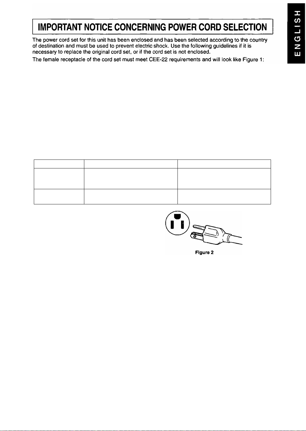
For the United States and Canada:
In the United States and Canada the male plug is a NEMA 5-15 style (Figure 2) and is UL listed and
CSA labelled. For units which are mounted on a desk or table, type SVT or SJT cord sets may be
used. For units which sit on the floor, only SJT type cord sets may be used. The cord set must be
selected according to the current rating for your unit. Please consult Table A for the selection criteria
for power cords used in the United States and Canada. (The cord set is marked with its Cord Type.)
For European Countries:
In Europe you must use a cord set which is appropriate for the receptacles in your country.
The cord set is HAR-Certified, and the mark 4 HAR k will appear on the outer sheath, or on
the insulation of one of the inner conductors.
If you have any questions concerning the proper power cord to use, please consult the dealer from
whom you have purchased your unit.
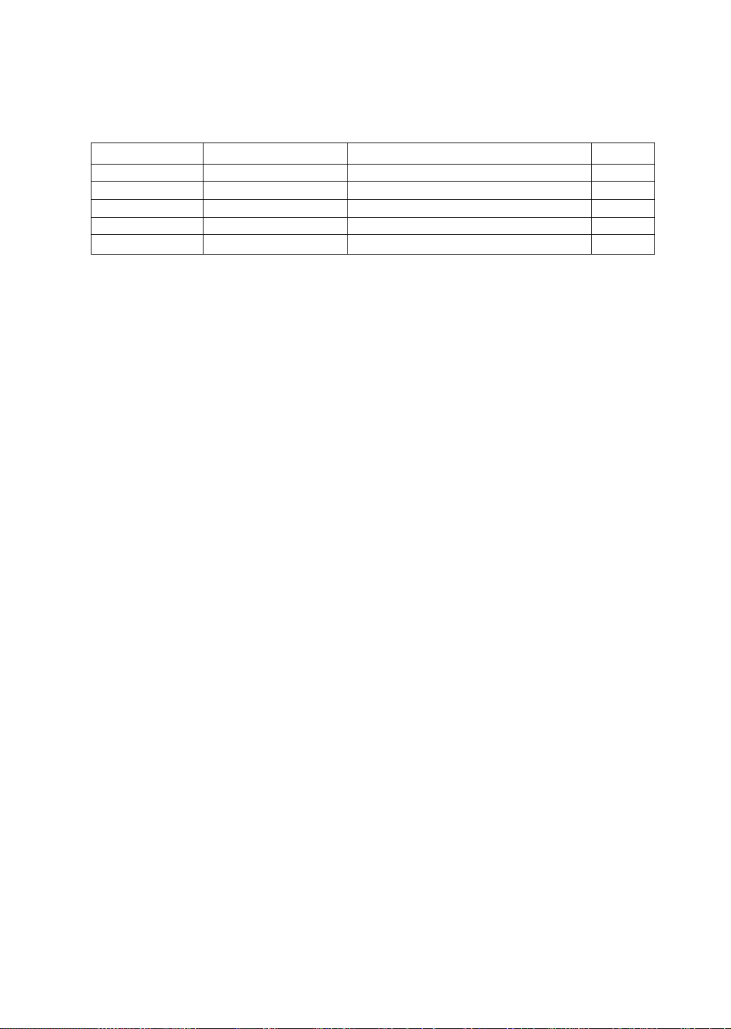
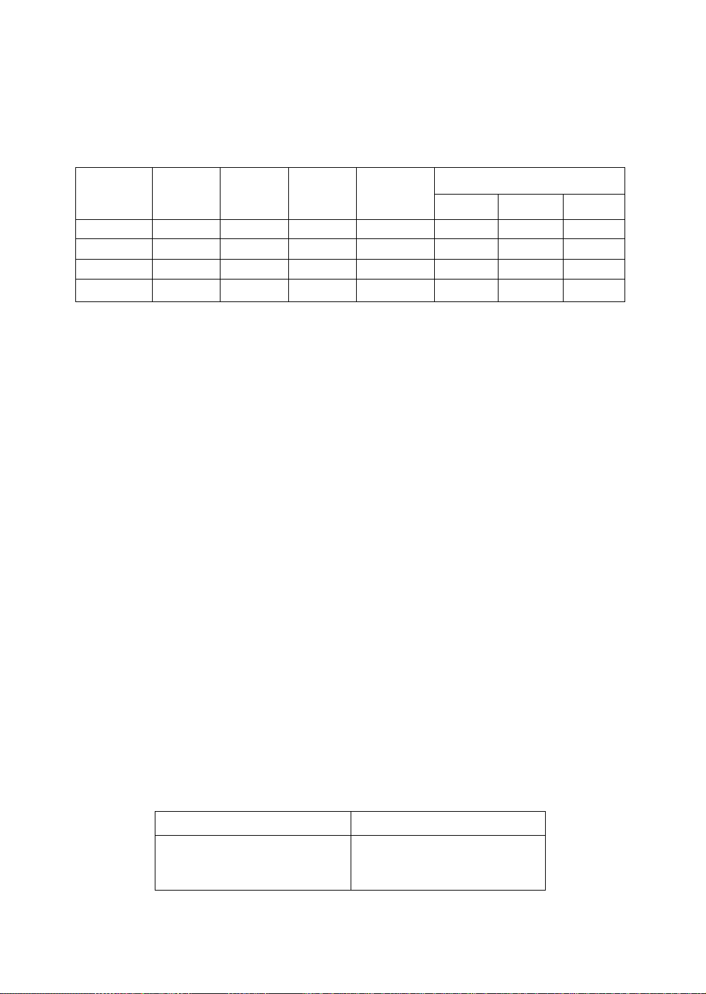
Table A
Cord Type Size of Conductors in Cord Maximum Current Rating of Unit
SJT
SVT
18 AWG
16 AWG
14 AWG
18 AWG
17 AWG 12 Amps
10 Amps
12 Amps
12 Amps
10 Amps
Figure 1
Federal Communications Commission Requirements
This equipment has been tested and found to comply with the limits for Class B digital devices,
pursuant to Part 15 of the FCC Rules. These limits are designed to provide reasonable protection
against harmful interference in a residential installation. This equipment generates, uses, and can
radiate radio frequency energy and, if not installed and used in accordance with the instructions, may
cause harmful interference to radio communications. However, there is no guarantee that interference
will not occur in a particular installation. If this equipment does cause harmful interference to radio or
television reception, which can be determined by turning the equipment off and on, the user is
encouraged to try to correct the interference by one or more of the following measures:
- Reorient or relocate the receiving antenna.
- Increase the separation between the equipment and receiver.
- Connect the equipment into an outlet on a circuit different from that to which the receiver is
connected.
- Consult the dealer or an experienced radio / TV technician for help.
FCC Warning:
To assure continued FCC compliance, the user must use the provided grounded power supply
cord and shielded interface cable with bonded ferrite cores. If BNC cable is going to be used,
use only shielded BNC (5) cable. Also, any unauthorized changes or modifications to this moni
tor would void the user’s authority to operate this device.
Page 3
CE Conformity
This device complies with the requirements of the EEC directive 89 / 336 / EEC as amended
by 92 / 31 / EEC and 93 / 68 / EEC Art. 5 with regard to “Electromagnetic compatibility” and
C€
TRANSIENT F/B #1 #3
LINE HARMONICS
#1 :Satisfies standards with no problems in performance and reliability.
#2 : Effects may appear temporarily on the screen but there will be no problem in reliability.
#3 : There is fear of the product breaking down.
#4 : If a signal cable other than that specified is used, it may be the cause of electromagnetic
Handle correctly in accordance with the instruction manual.
EMI: Electromagnetic Interference ESD : Electrostatic Discharge
RF : Radio Frequency F / B : Fast Burst
73 / 23 / EEC as amended by 93 / 68 / EEC Art. 13 with regard to “Safety".
Required item Relative to Standard Value Relative to those Exceeding Standard Value Remarks
EMI #1 -
ESD #2 #3
RADIATED RF #1 #3
#1
interference to peripheral devices.
To assure continued CE compliance the user must use the provided 1.5 m shielded video signal
cable with bonded ferrite cores at both ends of the cable.
-
Energy Star®
#4
-
-
-
-
As an Energy Star* partner, Panasonic Computer Peripheral Company has determined that
this product meets the Energy Star® guidelines for energy efficiency.
Notice for Germany
Note:
• For ergonomic reasons, it is recommend not to use blue characters on a dark background. Doing so may
produce insufficient contrast that could lead to eye strain.
German
HINWEIS:
• Aus ergonomischen Gründen wird empfohlen, die Grundfarbe Blau nicht auf dunklem Untergrund zu
verwenden (schlechte Erkennbarkeut, Augenbelastung bei zu geringem Zeichenkontrast wäre die Folge).
Notice for Japan
This is a Class B product based on the standard of the Voluntary Control Council for
Interference from Information Technology Equipment (VCCI). If this is used near a radio or
television receiver in a domestic environment, it may cause radio interference. Install and use
the equipment according to the instruction manual.
Japanese
(vccd <Dmmizmri<
aiißsi T? TIE utj at u ^ UTT $ Uo
Page 4

A A I Danger
To avoid the risk of severe electrical shock including death, do not remove covers
(or back) of monitor. No user serviceable parts are inside. Refer servicing to
qualified service personnei.
I
Warnings
To prevent risk of eiectric shock and possible fire:
Never place any object on the monitor, AC Power cord, or cause the cords to make
sharp bends, or otherwise do anything that can affect the integrity of the cords.
Always remove the line cord from the socket by holding the plug, not the cord.
Do not place anything containing any liquid (even a wet or damp cloth) on the
monitor as the introduction of fluids can create an electrical hazard. Do not expose
the monitor to rain or moisture.
Do not place the monitor with less than the recommended clearance (see
Precautions, 1 Installation Page 4). Do not block the ventilation openings with
anything. Do not insert any objects into the ventilation openings.
Customer’s Record
The serial number of this product is printed on its back cover label.
Note this serial number in the space provided and retain this booklet as a permanent record of
your purchase to aid in identification of the unit in the event of theft or loss.
Model number: TX-D9S55
Serial number:
Table of Contents
IMPORTANT NOTICE CONCERNING POWER CORD SELECTION
Federal Communications Commission Requirements
CE Conformity.........................................................................................................2
Energy Star®........................................................................................................2
Notice for Germany.................................................................................................2
Notice for Japan.................................................................................................... 2
Danger.....................................................................................................................3
Warnings................................................................................................................. 3
Customer’s Record..................................................................................................3
Table of Contents....................................................................................................3
Precautions 1) Installation.......................................................................................4
Precautions 2) Usage..............................................................................................4
Precautions 3) Product Care...................................................................................4
Features..................................................................................................................5
Specifications..........................................................................................................6
Installation...............................................................................................................7
Pin Assignment.......................................................................................................8
External View.......................................................................................................... 8
Operation.................................................................................................................9
Operation procedure
Adjustments...........................................................................................................10
Pedestal removal..................................................................................................13
Power Management System.................................................................................14
Memories...............................................................................................................14
Timing Specifications.............................................................................................15
Trouble Shooting...................................................................................................16
Technical Support
...............................................................................................
.................................................................................................
...........................................
.................
1
16
1
9
ALL PRODUCT / BRAND NAMES ARE TRADEMARKS OR REGISTERED TRADEMARKS OF THE RESPECTIVE HOLDERS.
© 1999 MATSUSHITA ELECTRIC INDUSTRIAL CO., LTD.
Page 5

Precautions
1) Installation
• Install the monitor in a well ventilated place. Avoid exposing to direct sunlight, a
heater, or any other heat source. Heat wilt adversely affect the cabinets and the parts
inside.
• Position the display unit so that the holes in the cabinet will not be blocked during use.
• Keep the display unit away from the kitchen, bathroom, washing machine, or other
sources of exposed to water, steam or moisture.
• In order to use the display unit safely, use only the supplied AC Power cord. The AC
Power cord must be used with a properly grounded and polarized power supply
socket. The AC Power cord supplied is for the USA (UL) and Canada (CSA) for use
with the display unit. For use in other countries, make sure the AC Power cord meets
the safety standards of the country.
• Place the AC Power cord where it will not be subject to stress.
• Use only Panasonic provided accessories or the exact equivalent.
2) Usage
• Pulling on the AC Power cord or VGA Signal Cable can damage the display unit
(monitor) and can cause the unit to fall and possibly cause personal injury.
• Receiving trouble.
If there is a television set or other display unit nearby, keep your display unit as far
away from it as possible. Mutual interference can cause image distortion or noise.
• Long exposure to rubber or vinyl products can stain the cabinet.
• Keep the monitor from physical shock when moving. Be careful of the Cathode Ray
Tube (CRT).
• Do not place anything on the monitor.
• Also take good care of the AC Power cord:
Do not place any objects on the AC Power cord. Do not attempt to extend, shorten or
tie it into a knot.
3) Product Care
• Prior to cleaning your display unit, disconnect the AC Power cord and the VGA Signal
Cable or BNC Cable from the display unit.
• Use a clean, soft, dry cloth to clean the outside of the monitor or the CRT surface.
If the monitor or CRT surface is very dirty, wet a clean, soft cloth with neutral
detergent (such as dishwashing detergent) and water, squeeze it tight until almost dry,
wipe the monitor or CRT surface with it, and finish by wiping with a clean dry cloth. Do
not use any solvents.
• Do not rub or strike the monitor with anything hard or harsh as this may scratch, mar
or damage the monitor permanently.
• Do not use a chemical duster or polish-cleaner because it can adversely affect the unit
and peel the paint coat.
Page 6

1) High Image Quality in a Shorter Length Package
• Panasonic PanaSync SL90i with a Short-Neck CRT 19" (18.0" / 45.7 cm Viewable Image Size) has image
quality that has to be seen to be believed. It has a 0.25 mm ultra tine dot pitch and up to 1600 x 1200
maximum resolution. The PanaSync SL90i produces sharp saturated color images with High Contrast and
Brightness that can be viewed over a wide viewing angle.
• Combined with optimized dynamic focusing circuitry, the Short-Neck CRT has improved beam landing
accuracy, focus, convergence, and lower raster distortion than a typical 19-inch CRT. This gives the
PanaSync SL90i a sharper, more uniform focus, especially in the corners of the screen, traditionally a focus
problem area. Crystal Pigment Phosphors and Advanced Invar Mask provide increased Contrast and
Brightness.
• PanaSync digital multi-scan 30 kHz to 97 kHz Horizontal and 50 Hz to 180 Hz Vertical scanning frequencies
can be automatically scanned. Eight timing selections have been preset at the factory and 20 user
programmable selections are provided.
2) Crystal Pigment Phosphors
• Crystal Pigment Phosphors provide increased brightness and contrast for the SL90i creating crisp colorful
images. Each grain of Crystal Pigment Phosphor is covered with a filter material of the same color to filter
external light.
3) Advanced INVAR Shadow Mask and Dark tint
• The Short-Neck CRT also features an Advanced INVAR Shadow Mask, which is manufactured with an
improved material and designed to be positioned closer to the screen glass. When combined with the Dark
tint of the screen, this results in a 10% overall increase in brightness, improved purity due to less
environmental movement, and better overall color uniformity.
4) New DQ-DAF^'^ Electron Gun with Super New OLF
• The new DQ-DAF (Double-Quadruple Dynamic Astigmatism and Focus) electron gun reduces the
degradation of the screen corner focus, realizing higher resolution. In addition, the super new OLF
(Overlapping Field) main lens for the SL90i creates a smaller spot size which contributes to sharper images.
5) Digital adjustment using on-screen Menu (OSM)
• The On-Screen Menu is available in five (5) languages. English, French, German, Italian or Spanish can be
selected. Custom adjustments can be made quickly and easily through the On-Screen Menu utilizing four
buttons on the front panel. The On-Screen Menu may be positioned in one of six locations on the Display
Screen. A Self-Test On-Screen display is provided with no signal input or an Error On-Screen Menu if the
Horizontal or Vertical Scanning frequencies are outside the specified range.
6) The SL90i is Plug & Play
• VESA® DDC^“ 1 / 2B compatible (Video Electronics Standards Association Display Data Channel). This
allows the SL90i to inform a compatible host of its capabilities that meet the Microsoft* / Intel® Plug & Play
Definition used by Windows® 95 and Windows® 98.
7) Self-test menu
• The display unit can be checked via the self-test menu displayed on the screen. This menu can be accessed
without a computer.
8) Environmentally Friendly
• The SL90i has a VESA® OPMS^“ power management circuit. When used with a DPMS™ compatible
graphics card, the power consumption of the SL90i can be reduced. This product conforms to the Energy
Star® program.
• All plastic parts are recyclable.
• Meets MPR II, TCO'92 and carries the CE mark.
9) Color Adjusting Function
• The White Reference Color Temperature is 9300K •+• 8 MPCD, 7500K, 6500K, 5000K, 9300K + 27 MPCD
or User Color which can be selected to adjust the red, green and blue signals of the monitor to match its
image to the output of a color printer.
10) Ergonomic Design
• Tilt & Swivel base with 90-degree pan to right or left and tilt angle of 13 degrees up a 4 degrees down.
• Advanced Anti-Glare, anti-Refection, Anti-Static screen coating.
Page 7
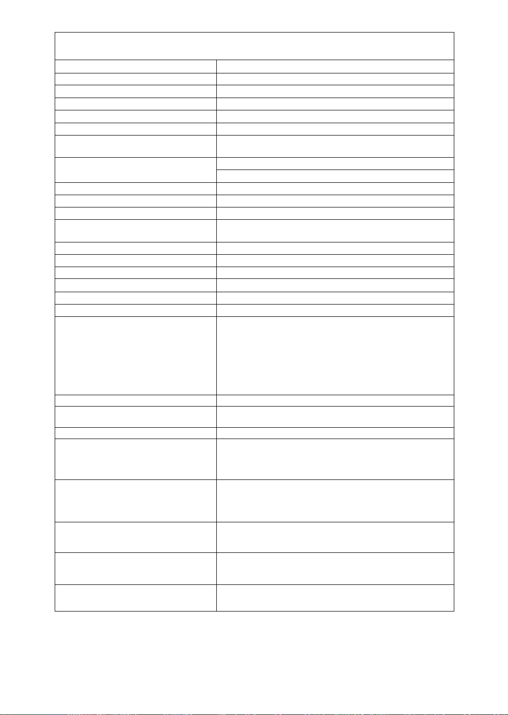
Specifications
CRT Size
Dot-pitch
Phosphor/Glass
Surface treatment
Input signals Video signaling
Signal level 0.7 Vp-p (without sync, signal), 1.0 Vp-p (with sync, signal)
Sync, signal
Frequency Range
Preset mode
Video Maximum Pixel Clock
Resolution
Viewable Image Size Factory preset
(H X V, Diagonal) Full scan (Typical)
Display Color
Connectors Video Signal
Power supply
Input power
Power consumption
Controls Front
On screen display
Tilt / swivel
Dimensions (W x H x D)
Weight (monitor only)
Approvals
Standard
Environmental conditions Operating
Storage
Windows® 95 / 98 Plug & Play
19" CRT (18.0“ / 45.7 cm Viewable Image Size) Flat Square
0.25 mm
RGB medium short persistence (Hi-EU RED), Crystal Pigment / Dark tint
B-AGRAS (Anti-Glare, anti-Reflective and Anti-Static) Coat
RGB analog
H / V separation (TTL level),Hd / V composition (TTL level),
Sync.-on-green
Horizontal Frequency: 30.0 kHz to 97.0 kHz
Vertical Frequency : 50.0 Hz to 180.0 Hz
1 preset and 7 resenration (See page 15)
202.5 MHz (typ.)
1,600 dots (H) X 1,200 lines (V) at 75 Hz*
13.86“ X 10.39", 17.3" Diagonal **
14.37" X 10.79“, 18.0" Diagonal **
Analog input, unlimited number of colors ***
15 pin mini D-Sub connector (female pins), BNC x 5
CEE 22 type 3-pin connector
100 to 240 VAC (50 or 60Hz)
125 W typ. / < 10 W stand-by, < 3 W sleep mode (See page 14)
Power ON / OFF, [a, a, B, [2] keys
Contrast, Brightness, Size & Pos. (Zoom, H. Position, H. Size,
V. Position, V. Size), Geometry (V. Pincushion, Side Pin. Bal.,
Trapezoid, Parallelogram, Top Corner, Bottom Corner, S-Curve 1,
S-Curve 2), Rotation (Tilt), Color Temp, (9300K + 8 MPCD, 7500K,
6500K, 5000K, 9300K + 27 MPCD, User), Recall, Video Level
/1 V), H. Moire, V, Moire, H.Convergence, V.Convergence,
(0.7 V
Linearity-C, Linearity-E, Language, OSD Position, Degauss, Signal,
Self-Test menu
13° up, 4° down, 90° each to right and left
17.6" X 17.9" X 16.3"
(448 mm x 454 mm x 415 mm)
20.5 kg (45.2 lbs)
UL1950, CSA 22.2 No.950, TUV / GS, CE / CISPR 22-B (EN55022),
NORDIC, FCC Class B, DHHS, HC, IC-B, VCCI Class B,
MPR II, TCO’92, Energy Star®,
ISO 9241-3 (Ergonomics) / -8 (Colors)
1 detachable signal cable for VGA, SVGA
1 detachable AC power supply cord
Tilt & Swivel base attached
Operating Instructions, Warranty card
Temperature 5 to 35‘C (41 to 95’F)
Humidity 5 to 90% (no condensation)
Altitude 10,000 ft
Temperature -20 to -t-60*C (-4 to 140° F)
Humidity 5 to 90% (no condensation)
Altitude 40,000 ft
VESA® DDC™ 1 / 2B meets Windows^ 95 / 98 Plug & Play
Requirements
Note:
• The on-screen image may flicker if the display is operated with the Vertical freq. under 60 Hz.
* This monitor may only be used in a commercial or industrial environment at resolutions above 1,600 x 1,200 at 75Hz.
" Depends on signal timing used, see page 15.
*** Number of colors depends on the Video Board used, memory installed, and RAMDAC {Random Access Memory
Digital to Analog Converter).
Specifications and design are subject to change without notice.
This product may be subject to export control regulations. Weight and dimensions shown are approximate.
Page 8
Installation
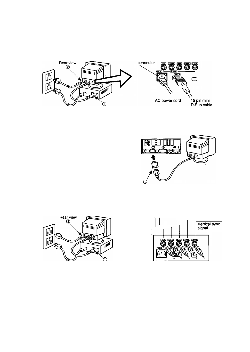
Connecting Procedures
Turn off your computer.
Connect the signal and power connectors as shown below.
Turn the monitor on, then turn on the computer.
A. IBM PS / 2 or compatible models
CEE22
(T) Connect the supplied 15 pin mini D-Sub cable to the monitor’s Port A.
Then connect the other end of the supplied 15 pin mini D-Sub cable to the computer's corresponding
15 pin mini D-Sub video connector.
(D First connect the supplied AC power cord to the CEE22 connector on the rear of the monitor.
Then connect the other end of the AC power cord to a grounded power outlet.
B. Apple computer
(T) Connect the supplied 15 pin mini D-Sub cable to the
monitor's Port A.
Then connect the other end of the supplied 15 pin mini
D-Sub cable to a UNIMAC-82D MAC adapter and the other
end of the MAC adapter the computers to the computer’s
corresponding 15 pin mini D-Sub video connector,
d) First connect the supplied AC power cord to the CEE22
connector on the rear of the monitor. Then connect the
other end of the AC power cord to a grounded power
outlet.
Panasonic MAC adapter
If your need an adapter and one is not provided by your dealer, call 1-800 PANASYS (1-800-726-2797).
— Caution:
To prevent the cable from coming loose, the cable connectors must be securely fastened with screws.
C. BNC connector signal computer
(D Connect the BNC signal cable (Not supplied) BNC connectors to the monitor’s Port B.
Then connect the other end of the BNC cable, usually a 15 pin mini D-Sub connector, to the computer’s
corresponding 15 pin mini D-Sub video connector.
(D First connect the supplied AC power cord to the CEE22 connector on the rear of the monitor.
Then connect the other end of the AC power cord to a grounded power outlet,
Blue video signal
Green video signal
or sync on green
Red video signal
Horizontal sync signal or
composite sync signal
4 Connection of AC Power Supply
If the AC power supply voltage is in the range 100 to 240 V, either 50 Hz or 60 Hz frequency can be used.
There is no AC 100 V / 240 V selector switch as selection is automatic.
Precaution:
• In order to use the display unit safely, use a power cord that Is properly grounded.
• AC plug cords for the following countries must be used as follows:
U.S.A
................
For use in other countries, make sure that the AC cord meets the safety standards of each country.
UL Canada
.............
* •
CSA
Page 9
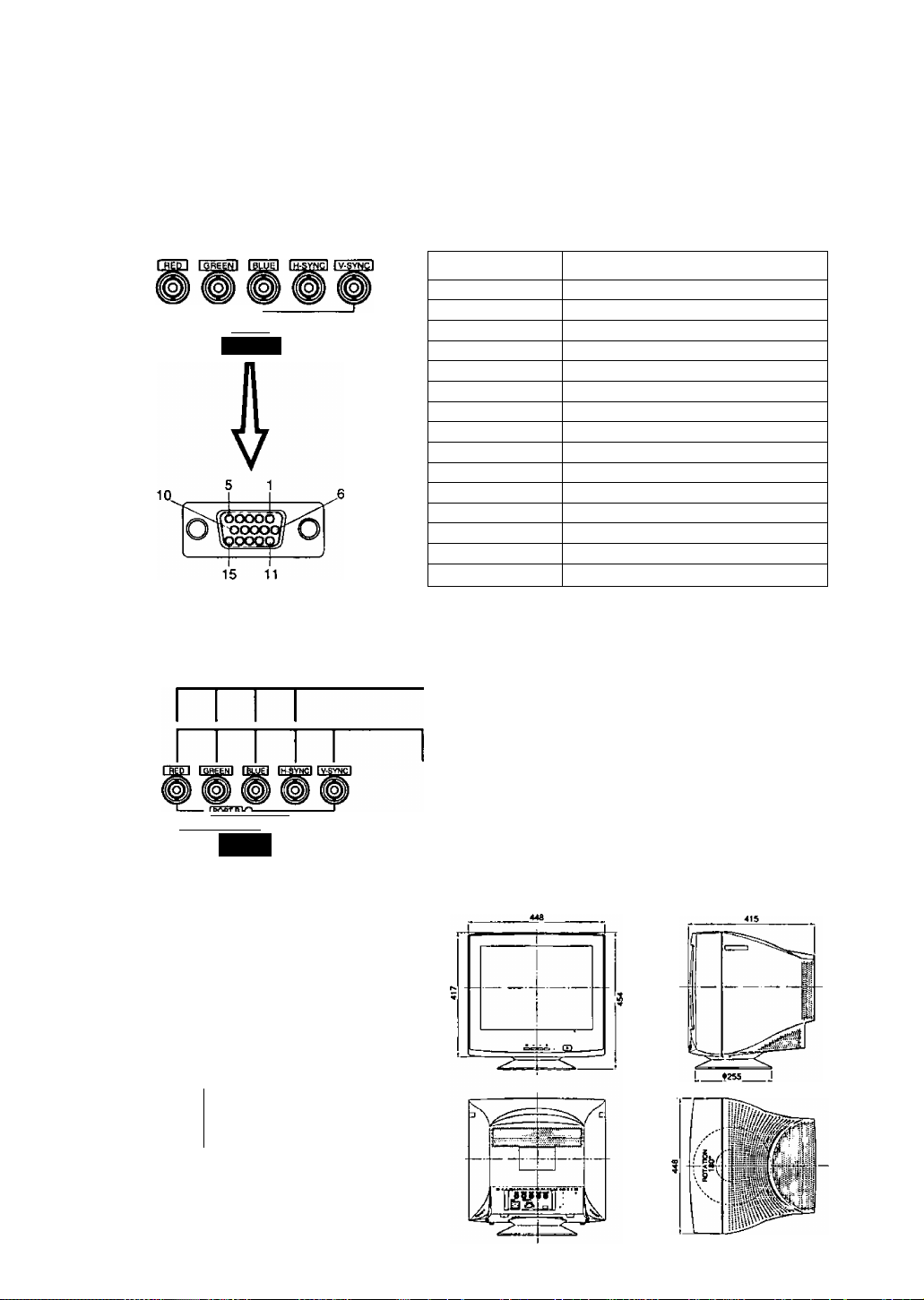
Pin Assignment
Follow the instructions below to connect the SL90i to a computer.
A. Signal connector: 15 pin mini D-Sub (PS / 2 or PC / AT compatible model)
Connect the signal cable to the 15 pin mini D*Sub connector on the dispiay unit.
B. Signal connector: 15 pin D-Sub (Apple computer)
Convert a MAC 15 pin D-Sub connector to a 15 pin mini D-Sub connector using a Panasonic MAC
adapter, and connect it to the 15 pin mini D-Sub connector on the dispiay unit.
< REAR PANEL >
-ITORTBK^
1>0RTA1
C. Signal connector; BNC connector
Pin assignments ot 15 pin mini D-Sub connector
Pin number Signal name
1 Red video signal
2 Green video signal
3 Blue video signal
4 Ground
5 Ground*
6 Ground for Red video signal
7 Ground for Green video signal
8 Ground for Blue video signal
9 Unused
10 Ground
11
12 SDA* (Bi-directional Data)
13
14
15
“VESA"s Display Data Channel (DDC) Standard
Sync on green system
Connect the signal cable to RED, GREEN (sync
ongreen) and BLUE BNC connectors.
Ground
Horizontal sync, signal
Vertical sync, signal
SCL* (Data Clock)
-(POflTBK>
I PORT *1
ME
External View
Dimensions
Width
Height
Depth
Base diameter
Height without stand
Pan / Tilt range
Up : 13 degrees
Down : 4 degrees
Left, right
: 90 degrees each
Composite sync system
Connect the signal cable to RED, GREEN, BLUE
and H-SYNC (H / V composite) BNC connectors.
Separate sync system
Connect the signal cable to RED, GREEN, BLUE
and H-SYNC and V-SYNC BNC connectors.
Note : If your computer's video output is over
110 MHz, it is recommended that it be
used with the BNC connectors.
448 mm (17.6")
454 mm (17.9")
415 mm (16.3")
<t>255 mm (<t>10.0")
417 mm (16.4")
8
Page 10
Operation
Basic operation
m
Displays main menu.
Exits menus.
(D
Selects menu item.
To scroll through menu item.
To adjust level of selected item.
Menu screen
The functions that can be adjusted for this unit are displayed as icons.
1) Press the [T] key to return to the menu screen.
2) This is modified by pressing the 3 and B keys at the front.
3) Press the [D key to enter the adjustment screen.
Contrast
o
s
o
iO
s
Rotation
H. Moira
Brightness Size & Pos. Geometry
Color Temp
V. Moire
S
p\
Contrast
Linearity-C Linearity-E Language
Degauss Signal
Recall
H. Convergence V. Convergence
Video Level
OSD
Position
Operation procedure
Horizontal position adjustment
1. Press the Q] key to display the menu.
2. Press the B key to select the Size & Pos. from
the menu screen.
Press the [H key to display the menu.
3. Press the [H key to select the H. Position.
4. Press the front 3 or B keys to reach the
desired condition.
5. Press the d] key to save the settings to memory
and complete the adjustments. Press the 0]
key once more to clear the menu screen.
(D < > [D
CZKZDCD
G) < > EJ
CZDCZDi
Q] < > E]
CD CD CD ca
(3 < > (D
Q < > ID
■a
o
o
[=i S
F\
3 *1^0
O C3
s a
P\
H. Position
50
E5
(7J
O
Contrast
È
Si ze & Pos.
iG
№i
to
Hms_a_L'iTE)
H. Position
70
a [PBeiriTgi
3 ^ ^ Q
O ® V
1^ H
FI «Hr
Size& Pos.
*o
®
Page 11

Adjustments
Adjustment menu
3 Contrast
Adjust the screen contrast to match the brightness level in the room.
Pressing the [U key toggles between brightness and contrast.
Direct operationi
Even if the menu screen does not appear, the contrast can be adjusted by pressing
the a or B key. If the a and B keys are pressed at the same time, the
maximum level (100) will be set.
Brightness : Adjust the brightness to match the brightness level in the room so that the level
will be easy to see.
Pressing the [U key toggles between contrast and brightness.
Note: If the a and B keys are pressed at the same time on the Brightness
adjustment screen, the standard level (50) will be set.
Size & Pos. ! Press the [D key to select the zoom / horizontal position / horizontal size / vertical
position / vertical size adjustments.
Press the [D key to save the adjustment.
Zoom
Both the horizontal and vertical size of the image can be adjusted at the same
time; however, the aspect ratio cannot be changed.
Press the a key to make the image smaller, the B key to make it larger.
H. Position ! The horizontal position of the image can be adjusted.
Press the a key to move it to the left, the B key to move it to the right.
H. Size ! The horizontal size of the image can be adjusted.
Press the a key to make the image smaller, the B key to make it larger.
Note: Setting the image in the center of the screen to start will make the
adjustment easier.
V. Position 1 The vertical position of the image can be adjusted.
Press the a key to make it downward, the B key to move it upward.
V. Size ! The vertical size of the image can be adjusted.
U]
Geometi7 : Press the [2] key to select the vertical pincushion / side pincushion balance /
o
___
Press the Q] key to save the adjustment.
Press the a key to make the image smaller, the B key to make it larger.
Note; Setting the image in the center of the screen to start will make the
adjustment easier.
trapezoid ,^arallelogram / Geometry 2 adjustments.
O V. Pincushion : The image can be corrected for barrel distortion.
Press the a key to decrease the Pin / Barrel distortion of the image,
the B key to increase it.
(i Side Pin. Bai. : It is possible to adjust the side pincushion balance to the left and right.
Press the 3 key to expand to the left of the image, the B key to
expand it to the right.
Trapezoid !The image can be corrected for trapezoidal distortion.
___
bottom edge narrower.
Press the 3 key to make the top edge narrower, the B key to make the
Parallelogram !The image can be corrected for parallelogram distortion.
Press the 3 key to collapse the parallelogram to the left, the B key
to collapse it to the right.
w w Geometry 2 ! Press the B key to change the sub OSD screen.
Press the [D key to select the Top Corner / Bottom Comer / S-Curve 1 /
S-Curve 2 adjustments.
O Top Corner I The image can be corrected for vertical pincushion distortion in the
top comer.
Bottom Corner ; The image can be corrected for vertical pincushion distortion in
o
S1 S-Curve 1
the bottom comer.
The image can be corrected for vertical pincushion distortion in the SCurve 1.
<=>
10
S2 S-Curve 2 ! The image can be corrected for vertical pincushion distortion in the S-
Page 12

Adjustments (Continued)
Acjjustment menu
tQi Rotation ! This control adjusts the evenness of the screen image relative to a horizontal line.
Note: If the 3 and B keys are pressed at the same time, the standard level
(50) will be set.
Ql Color Temp I It is possible to switch the whiteness of the image.
1) Press the H and B keys to select 1 (9300K + 8MPCD) / 2 (7500K) /
3 (6500K) / 4 (5000K) / 5 (9300K + 27MPCD) / 6 (User).
2) H] will be displayed at the bottom right-hand side of the on-screen
panel when 6 (User color) has been selected. Press the H] key on
the front operation area to enter the User color adjustment screen.
User : It is possible to adjust the whiteness of the image to suit personal
preference.
1) Select R (red), G (green), B (blue) with the \H key.
2) Adjust the color to match personal preference with a and B keys.
* As user colors cannot be recalled, take note of the set values
beforehand.
^ Recall: It is possible to return to the initial settings (the settings at the time of factory
shipment).
1) When the [D key (Yes) is pressed, the settings are recalled and the menu
screen returns. (Recall = return to initial settings (settings at time of factory
shipment))
2) When the [U key (No) is pressed, the menu screen returns without the settings
being recalled. (The settings return to what they were immediately before the
recall.)
If there are no operations performed for about 30 seconds, the screen goes off
without a recall.
Video Level : The video input signal level can be matched to the computer being used.
Either 0.7 V or 1.0 V can be selected with the [H (0.7 V /1 V) key.
Use 0.7 V under normal condition.
Moire reduction
Caution:
If the moire reduction is overcorrected, the picture quality (for example focus,
vertical line stability, etc.) will sometimes be affected.
Keep this adjustment within the range in which the picture quality is not affected.
H. Moire
Moire patterns are caused by interference of the CRT dot pitch and video
signal due to the resolution of the input signal, video pattern, etc., producing
patterns of horizontal stripes (Horizontal moire pattern) or vertical stripes
(Vertical moire pattern).
The moire correction circuit can be switched On and Off with the W key.
When the moire correction circuit is switched On with the ¡2} (On / Off) key, the
adjustment screen menu appears.
Adjust with the H and B keys so that the striped moire pattern is in its optimum
condition.
V. Moire
The moire correction circuit can be switched On and Off with the [H key.
When the moire correction circuit is switched On with the \J\ (On / Off) key, the
adjustment screen menu appears.
Adjust with the 3 and B keys so that the striped moire pattern is in its optimum
condition.
11
Page 13

Adjustments (Continued)
Adjustment menu
Convergence l convergence is affected by geomagnetism. Use this function when
These convergence adjustments should be made after monitor operation has
stabilized.
iHlHl H.ConV6rg©nCG ! Horizontal convergence of the image {color fringing) can be adjusted.
convergence error occurs after moving the monitor or changing the screen
angle.
Press [2] key to toggle between H.Convergence and V.Convergenmce.
Note: If the 3 and B keys are pressed at the same time on the
H.Convergence adjustment screen, the standard level (50) will be set.
Press the B key to move red to the right and blue to the left.
Press the 3 key to move red to the left and blue to the right.
V.Convergence Vertical convergence of the image (color fringing) can be adjusted.
Press d] key to toggle between V.Convergence and H.Convergence.
Note: If the 3 and B keys are pressed at the same time on the
V.Convergence adjustment screen, the standard level (50) will be set.
Press the B key to move red downwards and blue upwards.
Press the 3’key to move red upwards and blue downwards.
H Linearity-C : The image can be adjusted for vertical linearity in the center.
Press d] key toggle between Linearity-C and Linearity-E.
Note: It the 3 and B keys are pressed at the same time on the Lineahty-
C adjustment screen, the standard level will be set.
Press the B key to make the center linearity narrower.
Press the 3 key to make the center linearity wider.
B Linearity-E The image can be adjusted for vertical linearity in the edge.
Press [d key toggle between Linearity-E and Lineahty-C.
Note: It the 3 and B keys are pressed at the same time on the Linearity-
E adjustment screen, the standard level will be set.
Press the B key to make the bottom linearity wider.
Press the 3 key to make the top linearity wider.
Language : The language of the On-Screen Display can be selected from among
German, French, English, Italian and Spanish.
Select with the 3 or B key.
|08Df» OSD Position : It is possible to adjust the position and color that the on-screen panel
is to be displayed. The panel will rotate in a counter-clockwis direction
every time the [T] key is pressed.
jñ Degauss : Use this function to reduce the irregular colors in the image. The degaussing
operates for approximately five seconds after selection.
Use this function when irregular colors occur in the image after moving the
monitor or the changing the screen angle.
Note: Be informed that a continued use of this function cannot result in a
satisfactory effect. (Try to keep an interval of about 30 minutes or so between
operations.)
12
Page 14
Adjustments (Continued)
A(djustment menu
Signal ! Use the 3 and B keys to select either the rear panel input terminal port A
{Mini D-Sub type) or Port B (BNC) type.
This displays the input synchronization signal frequency.
Information on the input screen mode {resolution, horizontal and vertical
synchronization frequency) will be displayed on the display monitor. There are
occasions sometimes when some screen modes in use do not display any
resolution. Direct display allows this to be displayed on screen by pressing
the [H key even when the menu screen is not displayed.
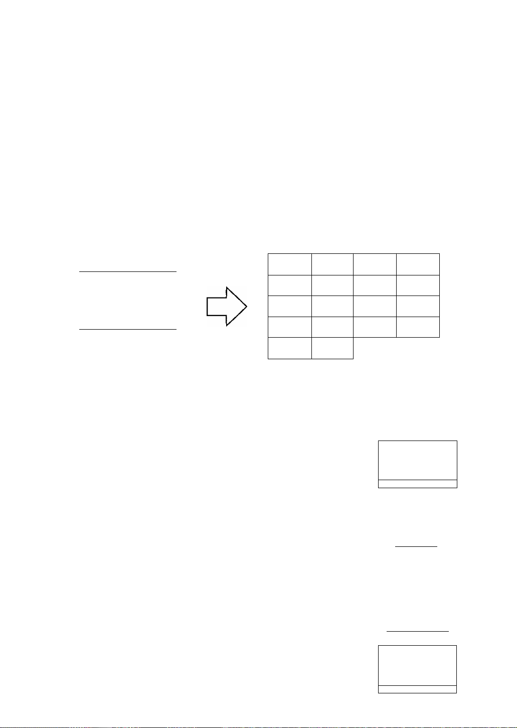
Self-Test menu (No Signal screen)
This display indicates that the monitor is operating normally. When one of the following
conditions occurs, press one of the 4 operation keys to call the appropriate display.
No Signal
fH —.—kHz
fV —Hz
Port ^ -O-
No signal {the computer is not connected,
the mains power to the computer is
disconnected or the input connector in
use may be deselected, see Page 13
Signal for instructions.)
The horizontal or vertical sync, signal are
outside of the permitted range (the value of
the horizontal sync, signal will be displayed
in red and the value of the vertical sync,
signal will be displayed in white.)
Error
fH 117.0kHz
fV 190.0 Hz
Port ^ -0-
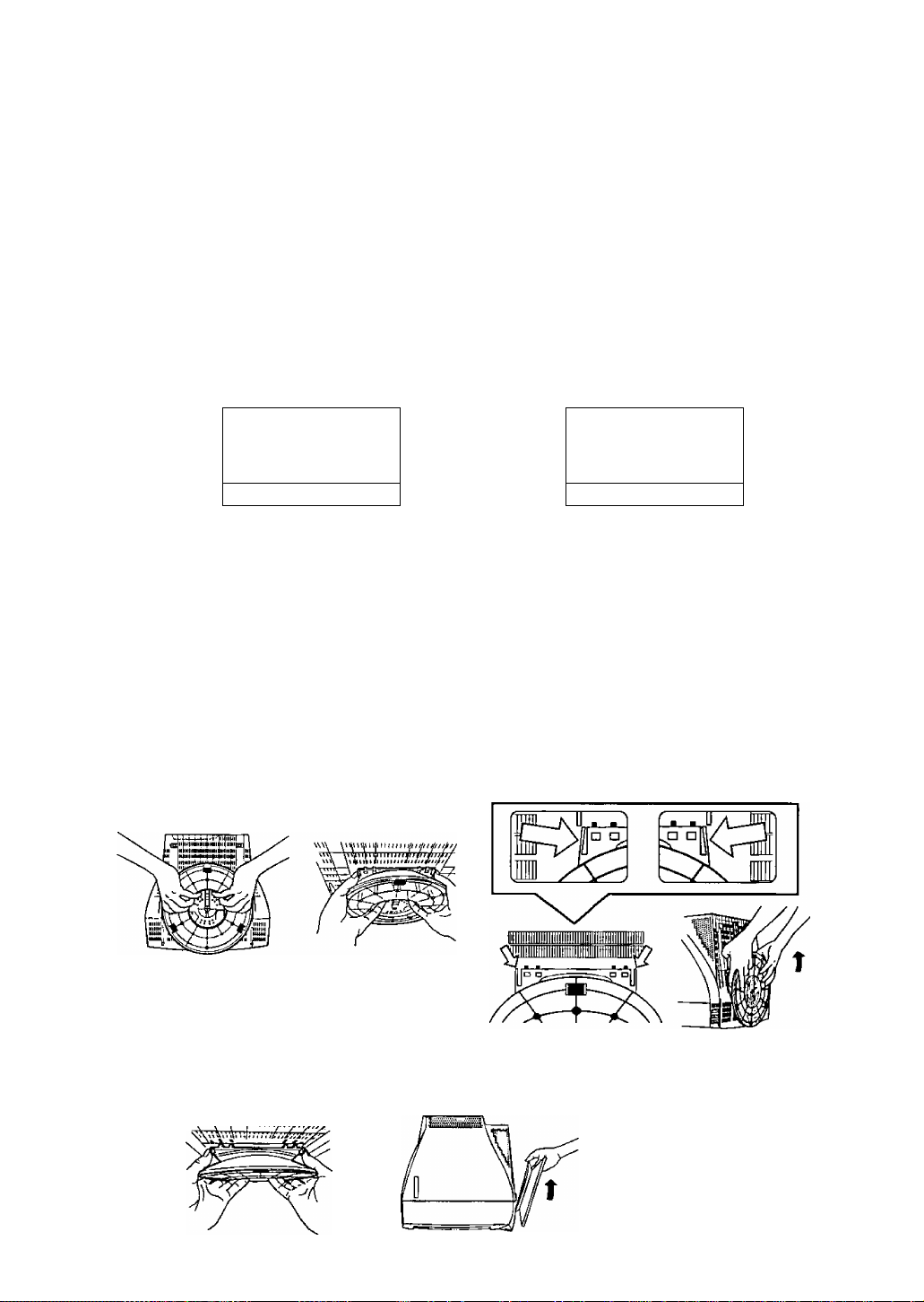
Pedestal removal
Observe the following instructions if the unit is to be used with the display stand removed.
Repeat this procedure in the reverse order if the display stand is to be reattached.
Lay the screen down onto a soft object (cushion,etc.) to avoid scratching.
Grasp the bottom of the display stand as
indicated in the illustration.
El Apply pressure with your fingers to the area
shown in the illustration and lift the stand
slightly in an upward direction.
This will release the lock.
□ Once the lock has been
released, remove your fingers
and firmly lift upwards at an
angle.
This will separate the
stand from the main
unit.
□ Place the unit on top of
the computer to be used
or on a tabletop.
Store the display stand in
the box or other receptacle
in which the computer was
purchased.
13
Page 15
Power Management System
This monitor conforms to the VESA® DPMS™ standard.
This function can suppress power consumption for the display unit.
The computer and video board being used must also conform to the VESA® DPMS™ standard.
* Consult the Operation Manuals for the hardware being used.
Modes change in response to input signals as indicated in the table below.
АРМ state
ON STATE
STAND-BY Black out Yellow
SUSPEND Black out Yellow
OFF STATE
АРМ : Advanced Power Management
Screen
status
Active Green Normal - ON ON ON
Black out Yellow < 3 Watts
LED color
Power
consumption
< 10 Watts < 3 sec. OFF OFF ON
< 10 Watts < 3 sec. OFF ON OFF
Recovery time
Video
< 20 sec.
Input signals
Horizontal
OFF OFF
Vertical
OFF
Caution
• Turn the monitor off when it is not to be used for a long time.
• How to release the system from the power management function
1) Read the Operation Manuals for the hardware you are using.
2) Press one of the (T|, Э, B, Ш keys on the front panel.
The No Signal screen appears, and the monitor side power management function is
released (only in OFF STATE).
Memories
This display has two types of memory to store the data sets that control the on-screen
image. The first type of memory is the Preset Memory which is set by the factory. The
second type is the User Memory which is set by the user. Both memories store the
Horizontal Size, Vertical Size, Horizontal Position, Vertical Position, Vertical Pincushion,
Side Pincushion Balance, Trapezoid, Parallelogram, Top Corner, Bottom Corner, S-Curve 1,
S-Curve 2, Video Level, Horizontal Moire, Vertical Moire, Linearity-C and Linearity-E
adjustments of the displayed image.
Preset Memory
There are 1 preset (7 reservation) timings that are set by the factory. The preset timing wiii automaticaiiy size
and center the image with video boards which use these timings. Please see page 15 for Timing Specifications.
User Memory
• There are 20 memory iocations that aiiow for user timing. The image size, position, geometric distortion are
adjusted by the user.
• If the User Memory is completely full, and a new set of data is saved, the oldest data set in the User Memory
will be deleted.
• The User Memory has priority over the Preset Memory.
• When the user timing is input, the Vertical, Horizontal frequencies and sync polarities of the signal are
compared with the previous data stored in memory. The input signal will be stored as a new data set if one of
its parameters is different from the previous stored one.
• The new input signal must have a frequency difference greater than that shown in the table below or a different
sync, polarity from that already stored. If the new timing data includes frequency changes greater than those
shown in the table below or sync, polarity changes, a new user memory setting will be stored. If the frequency
difference is smaller than that of the chart and the sync, polarities are the same, the existing settings will be
retained.
Horizontal frequency Vertical frequency
Low 30 kHz ± 0.4 kHz
to
Hi 97 kHz ±1.0 kHz
Low 50 Hz ± 0.6 Hz
to
Hi 180 Hz ±1.8 Hz
14
Please note if the timing does not meet the display specifications, the size and position adjustment may not
appear as desired. Be sure the horizontal and vertical timing are within the monitor specification range.
See page 15 for Timing Specifications, preset and reservation timing.
Page 16
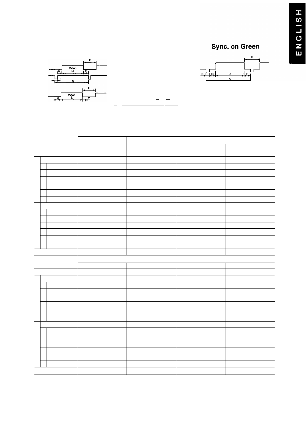
Timing Specifications
Separate Sync.
Preset timing* Reservation timing**
VESA1280x1024@85Hz
Dot clock
fH
A
H-Period
CO
F H-Blanking
c
О
H-Sync. width
В
N
C H-Back porch
о
X
D H-Active
E H-Front porch
fV
P
V-Period
U V-Blanking
Q V-Sync. width
О)
R V-Back porch
>
S V-Active
T
V-Front porch
Sync polarity (H / V) Positive / Positive Negative / Negative Positive / Positive
Dot clock 100.0000 MHz
fH
— A H-Period
F H-Blanking
c
о
В H-Sync. width
N
C H-Back porch
о
X
D
H-Active 11.520 us (1152 dots) 9.481 us (1280 dots) 8.466 us (1600 dots) 7.901 us (1600 dots)
E H-Front porch
fV
P V-Period
л
V-Blanking
U
V-Sync. width
Q
ф
R V-8ack porch
>
S V-Active 12.667 ms (870 lines) 12.804 ms (1024 tines) 13.714 ms (1200 lines) 12.800 ms (1200 lines)
T V-Front porch
Sync polarity (Н / V) Negative / Negative Positive / Positive
157.5000 MHz
91.146 kHz 31.469 kHz 53.674 kHz
10.971 us (1728 dots)
2.844 us ( 448 dots)
1.016 us { 160 dots) 3.813 us ( 96 dots) 1.138 us ( 64 dots) 1.016 us ( 96 dots)
1.422 us { 224 dots)
8.127 us (1280 dots)
0.406 us { 64 dots) 0.636 us ( 16 dots) 0.569 us ( 32 dots)
85.024 Hz 59.940 Hz 85.061 Hz 84.997 Hz
11.761 ms (1072 tines) 16.683 ms (525 lines) 11.756 ms (631 lines) 11.765 ms ( 808 lines)
0.527 ms ( 48 lines)
0.033 ms ( 3 lines) 0.064 ms ( 2 lines) 0.056 ms ( 3 lines)
0.483 ms ( 44 lines) 1.049 ms ( 33 lines) 0.503 ms ( 27 lines)
11.235 ms (1024 lines) 15.253 ms (480 lines)
0.011 ms{ 1 line ) 0.318 ms ( 10 lines) 0.019 ms ( 1 line ) 0.015 ms ( 1 line )
MAC 1152X870 ©75H2’*‘VESM280X1024 @75HzVESA1600X1200 @70HzVESA/UXGA1600X1200 075Hz
68.681 kHz 79.976 kHz 87.500 kHz 93.750 kHz
14.560 us (1456 dots) 12.504 US (1688 dots) 11.429 us (2160 dots)
3.040 us ( 304 dots)
1.280 us ( 128 dots) 1.067 US ( 144 dots) 1.016us( 192dots) 0.948 us ( 192 dots)
1.440 us ( 144 dots)
0.320 US ( 32 dots) 0.119us{ 16dots) 0.339 us ( 64 dots)
75.061 Hz 75.025 Hz 70.000 Hz 75.000 Hz
13.322 ms (915 lines) 13.329 ms (1066 lines) 14.286 ms (1250 lines) 13.333 ms (1250 lines)
0.655 ms ( 45 lines)
0.044 ms ( 3 lines) 0.038 ms ( 3 lines) 0.034 ms ( 3 lines) 0.032 ms { 3 lines)
0.568 ms ( 39 lines) 0.475 ms ( 38 lines) 0.526 ms { 46 lines) 0.491 ms ( 46 lines)
0.044 ms ( 3 lines) 0.013 ms ( 1 line ) 0.011 ms { 1 tine ) 0.011 ms { 1 line )
H / V Composite Sync.
—H VWeo
-------
~LT
Tn^innjj- ^ -ППППГ........... ............ ....... .......I Q I R| I S 11
VGA640X480 @60Hz
25.1750 MHz 56.2500 MHz 94.5000 MHz
31.778 US ( 800 dots) 18.631 us (1048 dots)
6.356 us ( 160 dots)
1.907 us ( 48 dots)
25.422 us ( 640 dots) 14.222 us( 800 dots)
1.430 ms ( 45 lines) 0.578 ms { 31 lines)
135.0000 MHz
3.022 us ( 408 dots) 2.963 us ( 560 dots) 2.765 us ( 560 dots)
1.837 us { 248 dots)
0.525 ms ( 42 lines)
4Л.
c-
U"
T' .1. Tj -Жтлп
VESA800X600 @85Hz VESA1024X768 ©85Hz
4.409 us ( 248 dots) 3.725 us ( 352 dots)
2.702 us( 152 dots) 2.201 us ( 208 dots)
11.179 ms (600 lines)
Reservation timing*'
1.608 us ( 304 dots) 1.501 us ( 304 dots)
0.571 ms ( 50 lines) 0.533 ms ( 50 lines)
Positive / Positive Positive / Positive
____
ППлЛЛг lil/lnnn^ 1—
14.561 us (1376 dots)
10.836 us (1024 dots)
0.508 us ( 48 dots)
0.582 ms ( 40 lines)
0.044 ms ( 3 lines)
0.524 ms ( 36 lines)
11.183 ms ( 768 lines)
189.0000 MHz 202.5000 MHz
10.667 us (2160 dots)
0.316 US ( 64 dots)
68.677 kHz
Positive / Positive
Note: All modes are Non-Interlaced.
* Factory Presets have exact size & centering.
" Factory Reservation have approximate size & centering.
*“ Requires the use of Optional Mac Adapter UN1MAC-82D.
15
Page 17

For safety, please observe the following points.
• When trouble occurs, turn the power OFF immediately and contact your dealer.
If smoke comes out of this unit or a bad odor or strange noise comes out, continuing to use
the unit can cause a fire or electrical shock. Turn the power OFF Immediately, unplug the
power cord from the outlet and contact your dealer.
A A
• Absolutely do not remove the rear cover.
There are parts at high voltage inside, so touching them can cause an electrical shock.
Leave inspection, adjustment and cleaning of the interior to your dealer.
• Do not put anything inside the casing.
If liquid or a foreign object should get inside accidentally, immediately turn the power OFF,
unplug the power cord from the outlet and contact your dealer. Continuing to use the unit can
cause a fire, electrical shock or breakdown of the unit.
If trouble occurs with the display unit, perform the following checks and take the indicated
action; if the trouble persists, please consult with your dealer.
Symptom Check
There is no display.
The image is too large or too small, or
it is displaced from the correct position.
power cord / plug
power switch
signal cable
The power saving function might
have acted (if so the pilot LED
will be yellow).
Check that the active input is
selected. See Page 13, Signal.
The mode is not registered.
Plug the power cord into the outlet correctly.
Press the power switch.
Connect the signal cable correctly.
Release the power saving function by operating
the mouse or keyboard.
For additional details please read the Operation
Manual of the hardware you are using.
Perform the desired settings and then save them
by waiting 20 seconds or pressing the Ш “Exif
key.
Action
□
The display color is abnormal.
(Example) The color is uneven or off-color.
The image distortion and or tilt is targe.
The background of the image is bright.
The background of the image is colored.
The character gets partially distorted.
The image is dark.
im ■
Characters cannot be seen dearly; the
image is too dark.
Is there something that produces
a magnetic field nearby?
(Examples) Television monitor,
another computer display unit,
speaker, etc.; was the orientation
of the monitor perhaps changed
while it was in use?
The computer in use is
Macintosh.
The signal output of the computer
in use IS improper.
Is the image signal level correctly
adjusted?
Is the brightness or contrast
adjustment turned all the way
down?
Remove the source of the magnetic field.
Perform degaussing.
Make sure your cable is correct.
Connect the signal connector correctly.
Try a different orientation.
Press the operating keys Ш and Ш together at
the same time. You can then adjust this unit with
the signal output of the computer. One more
pressing or execution of recall can cancel this
function.
* This function is effective for a specified
computer. If there is no problem in normal use,
avoid the use of this function.
Check the video signal level from the computer
and adjust it in the correct direction.
Adjust the brightness and contrast.
16
The screen size and position do not
change.
The front panel keys fail to operate. Are 2 or more keys being
If you have read the Operating Instructions and
tried the troubleshooting procedures and are
still having difficulty, please contact the dealer
from whom the unit was purchased.
You may also call the end user Technical
Support telephone number which is operational
twenty four (24) hours a day seven days a
week.
Is the input synchronization
signal within the operating
range?
operated at the same time?
To contact the Technical Support Group call:
1 -800-726-2797 (24 Hours a day)
To locate the Nearest Authorized Panasonic Service Center call:
1 -800-726-2797 (24 Hours a day )
To obtain Operating Instructions and Service Manuals call:
Phone : 1-800-833-9626 or 1-253-395-7343
Fax : 1-800-237-9080
(6:00 AM to 4:30 PM Pacific Time )
To locate the Nearest Sales Dealer call:
1-800-742-8086 (24 Hours a day )
To get the latest Windows* 95 / 98 Panasonic Monitor. INF Files call:
PanaTech BBS (201) 863-7845 (24 Hours a day )
You may also wish to see our world wide web pages at:
http://www.panasonic.com/alive
Check the video output mode from the computer,
and select a mode within the display unit
operating range.
For details, please read the Operation Manual of
the hardware you are using.
Operate only one key at a time.
Page 18

NOTICE IMPORTANTE CONCERNANT LE CHOIX DU CORDON D’ALIMENTATION
Le cordon d’alimentation de l’appareil se trouve dans l’emballage. Il a été sélectionné en fonction du
pays de destination et doit être utilisé pour éviter tout risque de choc électrique. Si l’on doit remplacer le
cordon d’origine, ou si le cordon ne se trouve pas dans l’emballage, observer les précautions suivantes.
Le receptacle femelle du cordon doit satisfaire aux normes CEE-22 et comporter les caractéristiques
présentées au Schéma 1.
Etas-Unis et Canada
Aux Etats-Unis ainsi qu’au Canada, la prise mâle est de type NEMA 5-15 (Schéma 2): elle est
mentionnée dans la liste UL et porte la mention CSA. En ce qui concerne les unités qui sont placées
sur une table ou sur un bureau, il est possible d’utiliser des cordons de type SVT ou SJT. Quant aux
unités qui sont placées à même te sol, seuls des cordons de type SJT peuvent être utilisés. Le choix
du cordon doit s’effectuer en fonction de l’ampérage de votre unité. Veuillez consulter le Tableau A
suivant les critères de selection des cordons d’alimentation utilisés aux Etats-Unis et au Canada. (Le
jeu de cordon est marqué du type du cordon.)
Pays européens:
En Europe, vous devez utiliser des cordon appropriés aux prises de votre pays. Les cordons
doivent être de marque 4 HAR ^ et celle-ci doit apparaître sur la gaine plastique externe ou
sur la partie isolante d’un des conducteurs internes.
Si vous avez des questions concernant le bon cordon à utiliser, vous êtes priés de consulter le
concessionnaire chez qui vous avez acheté votre appareil.
Tableau A
Type de cordon
SJT
SVT
Taille des conducteurs dans le cordon
18 AWG 10 Amps
16 AWG 12 Amps
14 AWG
18 AWG 10 Amps
17 AWG
Schéma 1
Ampérage maximum de l’unité
12 Amps
12 Amps
Conditions imposées par la commission fédérale des communications
L’appareil a été testé et jugé conforme aux limites des appareils numériques de classe B, aux termes
de la section 15 de la Réglementation FCC. Ces limites ont pour but d’assurer une protection
raisonnable contre les interférences parasites dans une installation résidentielle. Cet appareil
engendre, utilise et peut émettre une énergie radioélectrique et, s’il n’est pas installé et utilisé en
stricte conformité avec ces instructions, il peut provoquer des interférences parasites dans les
liaisons radiophoniques. Ceci ne garantit pas pour autant qu’une installation particulière n’émettra
aucune interférence. Si l'appareil engendre des interférences parasites avec la réception radio ou
télévision, ce qui pourra être déterminé et éteignant puis en rallumant l’appareil, il est conseillé à
l’utilisateur d’essayer de corriger les interférences en prenant l’une des mesures ci-dessous:
- Modifer l’orientation ou changer l’emplacement de l’antenne de réception.
- Eloigner davantage l’appareil du récepteur.
- Brancher l’appareil dans une prise d’un circuit différent de celui auquelle le récepteur est
raccordé.
- Demander l’aide de son agent ou d’un technicien radio / télévision qualifié.
Avertissement FCC:
Pour garantir une conformité constante à la Réglementation FCC, l’utilisateur devra utiliser un
cordon d’alimentation avec mise à la terre, et le câble d’interface vidéo blindé livré avec
l’appareil, avec tiges de ferrite incorporées. Si l’utilisateur prévoit d’utiliser un câble BNC, utiliser
exclusivement un câble BNC(5) blindé.
Par ailleurs, toute transformation ou modification non autorisée de l’appareil retirera à l’utilisateur
le droit d’utiliser ce moniteur vidéo.
17
Page 19

Conformité CE
Cet appareil est conforme aux exigences de la directive CEE 89 / 336 / CEE modifiée par
la directive 92 / 31/CEE et par l’article 5 de la directive 93 / 68 / CEE relative à la
C€
Interlérer>câ électromagnétique
Emission de radiofréquence
#1 : Satisfait aux normes sans problèmes de performance ni de fiabilité.
#2 : Des effets peuvent apparaître temporairement sur l'écran, mais il n’y aura pas de problème de
#3 : Risque de panne.
#4 : Si l’on utilise un câble de signal autre que celui spécifié, cela risque de provoquer un brouillage
Manipuler conformément aux instructions.
EMI : Perturbation électromagnétique ESD : Décharge électrostatique
RF : Radiofréquence F / B : Salve rapide
“compatibilité électronique”, et de la directive 73 / 23 / CEE modifiée par l’article 13 de la
directive 93 / 68 / CEE relative à la “Sécurité”.
Article exigé
Décharge électrostatique
Salve rapide transitoire
Harmoniques de ligne
fiabilité.
électromagnétique avec les périphériques.
Pour garantir une conformité CE continue, l'utilisateur devra utiliser le câble fourni, à savoir te câble
de signal vidéo blindé de 1,5 m avec âmes de ferrite assemblées aux deux extrémités du câble.
Par rapport aux valeurs standard
#1
#2 #3 -
#1
#1
#1
Par rapport â ceux dépassant les valeurs standard
-
#3
#3
-
Remarques
#4
-
-
-
ENERGY STAR
(g)
En sa qualité de partenaire d'ENEROv Star®, Panasonic Computer Peripheral Company a jugé
que ce produit respecte tes directive de rendement énergétique d’ENERcv Star®.
Notice pour rallemagne
REMARQUE :
0 Pour des raisons d'ergonomie, il est recommandé de ne pas utiliser la couleur bleue de base sur un fond
sombre (mauvaise reconnaissance, qui entraînerait une fatigue des yeux à cause du contraste insuffisant
des caractères).
Allemand
HINWEIS:
# Aus ergonomischen Gründen wird empfohlen, die Grundfarbe Blau nicht auf dunklem Untergrund zu
verwenden (schlechte Erkennbarkeut, Augenbetastung bei zu geringem Zeichenkontrast wäre die Folge).
Notice pour le japon
Cet appareil est classé dans la catégorie B, selon les normes définies par le Conseil de
contrôle volontaire sur les interférences (VCCI) de l’équipement pour la technologie
informatique. Utilisé à proximité d’un récepteur de radio ou de télévision dans les conditions
d’un domicile privé, il peut être à l’origine d’interférences des ondes radio. Installer et utiliser
l’appareil conformément aux instructions de la notice d’emploi.
18
Japonais
commit. (vcco
commit.
Page 20

A A [Panger
Pour éviter tout risque d’électrocution grave y compris de mort, ne pas retirer ies
couvercies (ni le dos) du moniteur. L*appareii ne renferme aucune pièce qui soit
réparabie par l’utiiisateur. Confier toute réparation à un personnel qualifie.
I
Avertissements
Pour éviter tout risque de choc électrique et de feu :
Ne Jamais rien poser sur le moniteur, le cordon d’alimentation secteur, veiller à ne pas trop
plier les cordons, et ne rien faire qui puisse affecter l’intégrité des cordons. Toujours
débrancher te cordon d’alimentation secteur de la prise en tirant sur la prise et non sur le
cordon proprement dit.
Ne pas poser de récipient renfermant des liquides (même un chiffon humecté de liquide)
sur le moniteur car ta pénétration de liquides pourrait être source de danger électrique. Ne
pas exposer le moniteur ni l’adaptateur secteur à la pluie ou à l’humidité.
Ne pas installer le moniteur sans respecter le jeu spécifié (voir les précautions, 1
Installation, Page 20). Ne pas boucher les orifices de ventilation. Ne pas insérer d’objets
dans les orifices de ventilation.
Renseignements à relever par le client
En cas de vol ou de perte, il est important de conserver le No. de série dans un dossier afin de
permettre l’identification. Noter le numéro de série dans l’espace prévu et conserver ce manuel à
titre de consignation permanente de l’achat. Il aidera à identifier l’appareil en cas de vol ou de perte.
Numéro de modèle
Numéro de série
TX-D9S55
Table des matières
NOTICE IMPORTANTE CONCERNANT LE CHOIX DU CORDON D'ALIMENTATION.17
Conditions imposées par la commission fédérale des communications
Conformité CE.........................................................................................................18
Energy Star®........................................................................................................18
Notice pour l’allemagne..........................................................................................18
Notice pour le japon................................................................................................18
Danger....................................................................................................................19
Avertissements........................................................................................................19
Renseignements à relever par le client..................................................................19
Table des matières.................................................................................................19
Mesures de précaution 1) Installation.....................................................................20
Mesures de précaution 2) Utilisation
Mesures de précaution 3) Soin du produit..............................................................20
Caractéristiques..................................................................................................... 21
Fiche technique...................................................................................................... 22
Installation...............................................................................................................23
Affectation des broches..........................................................................................24
Aspect extérieur.................................................................................................... 24
Fonctionnement......................................................................................................25
Procédure de fonctionnement.................................................................................25
Réglage...................................................................................................................26
Retrait du socle.......................................................................................................29
System de gestion d'énergie...................................................................................30
Mémoires................................................................................................................ 30
Spécifications de synchronisation..........................................................................31
En cas d’anomalie...................................................................................................32
Assistance technique..............................................................................................32
......................................................................
................
17
20
TOUS LES NOMS DE PRODUIT / MARQUE SONT DES MARQUES DE FABRIQUE OU DES MARQUES DÉPOSÉES DES DÉTENTEURS RESPECTIFS.
© 1999 MATSUSHITA ELECTRIC INDUSTRIAL CO., LTD.
19
Page 21

Mesures de précaution
1) Installation
• Installer le moniteur dans un endroit suffisamment aéré. Eviter toute exposition en
plein soleil et à des sources de chaleur {appareil de chauffage, etc.). La chaleur
aurait des conséquences néfastes sur les coffret et sur les pièces internes.
• Placer l’écran de façon que les orifices du coffret ne soient pas obstrués pendant le
fonctionnement.
• Eloigner l’écran des cuisines, salles de bains, lave-linge et autres sources d’eau, de
vapeur et d’humidité.
• Pour utiliser l’écran en toute sécurité, utiliser exclusivement le cordon d’alimentation
fourni. Le cordon d’alimentation secteur devra être branché dans une prise secteur
correctement mise à la terre et polarisée. Le cordon d’alimentation secteur fourni
convient pour un usage aux Etats-Unis (UL) et au Canada (CSA), et on l’utilisera
avec l’adaptateur secteur fourni avec l’écran. Pour les autres pays, bien utiliser un
cordon qui respecte les normes de sécurité du pays en question.
• Placer le cordon d’alimentation dans un endroit où il ne subira pas de contrainte.
• Utiliser exclusivement les accessoires Panasonic fournis, ou des équivalents exacts.
2) Utilisation
• Ne pas tirer sur le cordon d’alimentation secteur, le cordon d’alimentation CC ni le
câble de signal VGA car cela pourrait endommager l’écran (le moniteur), faire tomber
l’appareil et provoquer des blessures.
• Anomalies de réception
S’il y a un téléviseur ou un autre écran à proximité, éloigner l’écran le plus possible.
Les interférences mutuelles pourraient provoquer une distorsion des images ou des
parasites.
• Un contact prolongé avec des produits en caoutchouc ou en vinyle risque de tacher
le coffret.
• Lors du transport, protéger le moniteur contre les chocs. Faire attention au tube
cathodique.
• Ne rien poser sur le moniteur.
• Toujours faire attention au cordon d’alimentation.
Ne rien poser sur le cordon d’alimentation. Ne pas tenter de le rallonger, de le
raccourcir ni d’y faire des noeuds.
20
3) Soin du produit
• Avant de nettoyer le moniteur, débrancher le cordon d’alimentation secteur et le
câble de signal VGA du moniteur.
• Nettoyer l’extérieur du moniteur ou la surface de l’écran à l’aide d’un chiffon propre,
doux et sec. Si le moniteur ou la surface de l’écran sont très sales, humecter un
chiffon doux et propre de détergent neutre (par exemple un produit à vaisselle) et
d’eau, bien le tordre de façon qu’il soit presque sec, essuyer le moniteur ou la
surface de l’écran avec, puis les essuyer à nouveau avec un chiffon propre et sec.
Ne pas utiliser de solvants.
• Ne pas frotter ni heurter te moniteur avec quelque chose de dur ou de cassant car
cela pourrait le rayer, l’abtmer ou l’endommager irrémédiablement.
• Ne pas utiliser de chiffons chimiques ni de chiffons à cire car ils pourraient
endommager l’appareil et provoquer un enlèvement de la peinture.
Page 22

Caractéristiques
1) Haute qualité d’image sous un format plus court
• Le moniteur Panasonic PanaSync SL90i avec écran 19“ à plat (surface utile de visionnement de 18,0“/
45.7 cm) offre une qualité d'image qu’il faut voir pour y croire. Il possède un pas de masque ultra fin de
0,25 mm et une résolution maximale de 1600 x 1200. Le PanaSync SL90i à écran plat produit des image
couleur saturées nettes avec un haut niveau de contraste et de luminosité qui peuvent être visionnées sur
un grand angle de visionnement.
• Combiné aux circuits de mise au point dynamiques optimisés, l’écran plat offre une meilleure précision de
touche du faisceau, une meilleure convergence de mise au point et une plus faible distorsion de trame que
les écrans 19" classiques. Cela donne au PanaSync SL90i une mise au point plus nette et plus uniforme,
en particulier dans les coins de l'écran, qui posent généralement un problème de mise au point. Les cristaux
de phosphore pigmentés et le masque Invar de pointe contribuent à améliorer le contraste et la luminosité.
• Les fréquences horizontales de 30 kHz à 97 kHz et verticales de 50 Hz à 180 Hz de multi-balayage
numérique du PanaSync sont balayées automatiquement. Huit réglages de synchronisation ont été
présélectionnés en usine, et vingt peuvent être programmées par l'utilisateur.
2) Cristaux de phosphore Pigmentés
• Les cristaux de phosphore pigmentés renforcent la luminosité et le contraste du SL90i pour donner des
images couleur nettes. Chaque grain de cristal de phosphore pigmenté est recouvert d’une matériau filtrant
de la même couleur pour filtrer la lumière externe.
3) Masque image INVAR de pointe à teinte sombre
• L’écran plat possède également un masque image INVAR de pointe fabriqué dans un matériau amélioré et
disposé plus près du verre de l’écran. Combiné à la teinte sombre de l’écran, il donne une amélioration
d’ensemble de la luminosité de 10%, une meilleure pureté du fait de la réduction des mouvements de
l’environnement, et une meilleure uniformité d’ensemble des couleurs.
4) Nouveau canon à électrons DQ-DAF“ avec nouveau Super OLP
• Le nouveau canon à électrons DQ-DAF (Double-Quadruple Dynamic Astigmatism and Focus) réduit la
dégradation de la mise au point dans tes coins de l’écran, permettant une résolution supérieure. De plus, la
nouvelle lentille principale Super OLF (Overlapping Field) du SL90Í réalise une taille de point encore plus
petite, et donc des images plus nettes.
5) Réglage numérique par menu sur écran (OSM)
• Le menu sur écran existe en cinq (5) langues au choix : allemand, français, anglais, italien et espagnol. Les
réglages personnalisés s’effectuent rapidement et simplement avec le menu sur écran à l'aide de quatre
touches sur le panneau avant. Le menu sur écran peut être positionné dans l’un des six emplacements
disponibles, sur l’affichage. Un écran d’auto-diagnostic apparaît sans envoi de signal ou un menu sur écran
d’erreur si les fréquences de balayage horizontale et verticale se trouvent en dehors de la plage nominale.
6) Le SL90Í est compatible Plug & Play
• Compatible VESA* DDC™ 1 / 2B (Video Electronics Standards Association Display Data Channel). Ce
format permet au SL90I d’informer un serveur compatible de ses capacités respectant la définition
Microsoft*/ Intel* Plug & Play utilisée par Windows* 95 et Windows® 98.
7) Menu d’essai automatique
• Sans même avoir à brancher un ordinateur, le moniteur peut être vérifié en faisant apparaître le menu
d’essai automatique par l’intermédiaire des renseignements sur l’écran.
8) Respecte l’environnement
• Le SL90Í possède un circuit de gestion d’énergie VESA* DPMS™. S’il est utilisé avec une carte graphique
compatible DPMS^^, la consommation d’énergie du SL90Í sera réduite. Cet appareil respecte le programme
Energy Star®.
• Toutes les pièces en plastique sont recyclables.
• Respecte MPRll, TCO’92 et porte la marque CE.
9) Fonction de réglage couleur
• La température de couleur de référence du blanc est de 9300 K -h 8 MPCD, 7500 K, 6500 K, 5000 K, 9300
K -t- 27 MPCD, ou la couleur utilisateur peut être sélectionnée pour le réglage des signaux du rouge, du vert
et du bleu du moniteur de façon à faire correspondre l'image à la sortie d’une imprimante couleur.
10) Design ergonomique
• Socle orientable avec angle de réglage horizontal de 90 degrés vers la gauche et vers la droite, et angle de
réglage vertical de 13 degrés vers le haut et de 4 degrés vers le bas.
• Revêtement d’écran anti-éblouissement, anti-réflexion et anti-statique de pointe
21
Page 23

Fiche technique
Tube à rayons Taille
cathodiques Ecrat de point
Phosphore / Verre
Traitement de surface
Signaux d’entrée Signaux vidéo
Niveau de signal
Synchronisation de
signal
Limites de fréquence admissible
Mode prémémorisé
Vidéo Horlog de pixel maximum
Résolution
Zone utile du moniteur Préréglage usine
(H X V, diagonale) Balayage total (typ.)
Palette de couleurs affichées;
Prises Signal Miniprise à 15 broches D-Sub (femelle), BNC x 5
Alimentation
Alimentation
Cosommation
Commandes En Façade
Affichage sur l’écran
Inclinaison/pivotement
Dimensions (L x H x P):
Poids (moniteur seulement)
Homologation UL1950, CSA 22.2 No.950, TÜV / GS, CE / CISPR 22-B (EN55022),
Accessoires standard
Conditions ambiantes
En service Température
Taux d’humidité
Altitude
En stockage Tempe rature
Taux d’humidité
Altitude
Windows® 95 / 98 Plug & Play
Remarque:
• L’image sur l’écran risque de scintiller stle le moniteur est mis en service-selon u ne fréquence verticale inférieure à
60 Hz.
* Ce moniteur ne peut être utilisé que dans un environnement commercial ou industrie! à une résolution supérieure à
1.600x1.200 75 Hz.
** Suivant le signal de synchronisation qui est utilisé, se reporter à la page 31.
"* Le nombre de couleurs dépend de la carte vidéo utilisée et de la mémoire installée et du RAMDAC (convertisseur
numérique-analogique convertisseur de mémoire vive).
Les spécifications et la conception sont sujettes à modification sans préavis pour des raisons d’amélioration.
Ce produit peut être soumis à une réglementation de contrôle des exportations.
Ecran carré plat de 19 pouces (surface de visionnement de 18,0"/45,7 cm)
0,25 mm
Pigment de Cristal à persistance courte RVB (HI-EU Rouge) / Teinte sombre
Revêtement B-AGRAS (anti-éblouissant, anti-réfléchissant, antistatique)
Analogiques RVB
0,7 Vcc (sans signal de synchronisation), 1,0 Vcc (avec signal de synchronisation)
Séparation H / V (niveau TTL), H / V composite (niveau TTL),
Synchronisation sur le vert
Fréquence horizontale: 30,0 kHz à 97,0 kHz
Fréquence verticale: 50,0 Hz à 180,0 Hz
1 préréglés, 7 réservations (Voir page 31 )
202,5 MHz (typ.)
1.600 points (H) X 1.200 lignes (V) / 75 Hz*,
352 X 264 mm, diagonale 439 mm**
365 X 274 mm, diagonale 457 mm**
Entrée analogique, nombre illimité de couleurs**
Prise à 3 broches de type CEE 22
Courant alternatif 100 à 240 V (50 ou 60 Hz)
125 W typ / xattente 10 W, < mode dB dormir 3 W (Voir page 30)
Interrupteur d’alimentation Louches D], H, B, [H
Contraste, Luminosité, Cadrage (Zoom, Position H., Taille H.,
Position V., Taille V.), Géométrie (Coussin V., Adj. Coussin,
Trapezoidal, Pararellogra., Coin Sup., Coin Inf., Correc. SI,
Correo. S2), Rotation (Inclinaison), Tempera. Col. (9300K +
8MPCD, 7500K, 6500K, 5000K, 9300K -H 27MPCD, Perso.),
Valeurs Usine, Niveau Vidéo (0,7 V /1 V), Moiré H., Moiré V.,
Covergence H, Convergence V, Lin, Centre, Lin. Bord, Langue,
OSD Position, Demagnetis., Signal, Monitor Self-Test
En retevage 13" en abaissement 4" vers la droite 90"
448 mm X 454 mm x 415mm
20,5 kg (45.2 Ibs)
NORDIC, FCC Class B, DHHS, HC, IC-B, VCCI Class B,
MPR II, TCO’92, Energy StaH®,
ISO 9241 -3 (Ergonomics) / -8 (Colors)
1 câble de signal fixe pour VGA, SVGA
1 cordon d’alimentation secteur amovible
Socle orientable fourni.
Notice d’instructions, carte de garantie.
5"C à -t-35"C
5 à 90% (sans condensation)
3000 mètres
-20 à -t-60"C
5 à 90% (sans condensation)
12000 mètres
VESA® DDC^“ 1 / 2 B
(Satisfait aux exigences Plug & Play de Windows® 95 / 98.)
22
Page 24

Procédures de branchement
Mettre l'ordinateur hors tension.
Raccorder les connecteurs de signal et d’alimentation comme indiqué cidessous.
Mettre le moniteur, puis l’ordinateur sous tension.
A. Modèles IBM PS / 2 ou PC / ATcompatibles
Ф Raccorder le câble à miniprise à 15 broches D-Sub fourni au port A du moniteur.
Puis, raccorder l’autre extrémité du câble à miniprise à 15 broches D-Sub fourni au connecteur
vidéo à miniprise à 15 broches D-Sub correspondant de l’ordinateur.
Ф Raccorder tout d’abord le cordon d’alimentation secteur fourni au connecteur CEE22 au dos du
moniteur. Puis, raccorder l’autre extrémité du cordon d’alimentation secteur à une prise secteur
avec mise à la terre.
Connecteur CEE22
B. Ordinateur Apple
Ф Raccorder le câble à miniprise à 15 broches D-Sub fourni
au port A du moniteur.
Puis, raccorder l’autre extrémité du câble à miniprise à 15
broches D-Sub fourni à l’adaptateur MAC UNIMAC-82D et
l’autre extrémité de l’adaptateur MAC au connecteur vidéo à
miniprise à 15 broches D-Sub correspondant de l’ordinateur.
® Raccorder tout d’abord le cordon d'alimentation secteur fourni
au connecteur CEE22 au dos du moniteur. Puis, raccorder J
l’autre extrémité du cordon d’alimentation secteur à une prise Г
secteur avec mise à la terre. ф
Adaptateur MAC Panasonic
Si l’on a besoin d’un adaptateur et qu’il n’en est pas livré, appeler le 1-800 PANASYS (1-800-726-2797)
Attention:
Pour éviter que le câble ne se débranche, fixer solidement les connecteurs de câble à l’aide des vis.
D-Sub
C. Lorsque le connecteur de signaux est un connecteur BNC
Face arrière
® Raccorder le câble de signal BNC (non fourni) aux connecteurs BNC du port B du moniteur.
Puis, raccorder l'autre extrémité du câble BNC, généralement avec miniprise à 15 broches D-Sub,
au connecteur vidéo à miniprise à 15 broches D-Sub correspondant de l’ordinateur,
d) Raccorder tout d’abord le cordon d’alimentation secteur fourni au connecteur CEE22 au dos du
moniteur. Puis, raccorder l’autre extrémité du cordon d’alimentation secteur à une prise secteur
avec mise à la terre.
[ Signal vidéo bleu
Signal vidéo vert
ou sync vert
Signal vidéo rouge
Signal de synchronisation horizontale ou
signal de synchronisation composée.
Signal de
synchronisation verticale
4Raccordement de l’alimentation secteur
Si la tension de l’alimentation secteur est comprise dans la plage de 100 V à 240 V, on pourra utiliser ta
fréquence de 50 Hz ou de 60 Hz. Il n’y a pas de sélecteur CA 100 V / 240 V, la sélection étant automatique.
— Mesures de précaution:
Utiliser un cordon d’alimentation secteur doté d’un fil de terre approprié pour avoir la certitude d’utiliser le
moniteur vidéo en toute sécurité.
• La fiche du cordon d’alimentation secteur pour les pays ci-dessous doit être utilisée comme suit:
Quand l’appareil est appelé à fonctionner dans d’autres pays, il convient de vérifier que le cordon d’alimentation
secteur utilisé est bien conforme aux normes imposées dans chacun des pays.
Etats-Unis
.........
UL Canada
....................
CSA
23
Page 25

Affectation des broches
Se conformer aux instructions ci-dessous pour raccorder le SL90i à un ordinateur.
A. Prise de signal: Miniprise à 15 broches D-Sub (modèles PS / 2 ou PC / AT compatibles)
Raccorder le câble de liaison de signal à la miniprise à 15 broches D-5ub au moniteur.
B. Prise de signal: Prise à 15 broches D-Sub (Ordinateur Apple)
Convertir une prise à 15 broches D-Sub MAC en mini-prise à 15 broches D-Sub en utilisant un
adaptateur Mac Panasonic, et la raccorder à la miniprise à 15 broches D-Sub du moniteur vidéo.
< Panneau arrière >
Affectation des broches de la miniprises à 15 broches D-Sub
Numéro de broche
1 Signal vidéo du rouge
2 Signal vidéo du vert
3 Signal vidéo du bleu
4 Masse
5 Masse*
6
7 Masse du signal vidéo du vert
8 Masse du signal vidéo du bleu
9
10 Masse
11
12 SDA* (Données bi-directionnelles)
13
14
15 SCL* (Données d’horloge)
*: Normes DDC (Display Data Channel) de “VESA”
Masse du signal vidéo du rouge
Libre
Masse
Signal de synchronisation horizontale
Signal de synchronisation verticale
Nom du signal
C. Lorsque le connecteur de signaux
est un connecteur BNC
A titre de référence:
Si la sortie vidéo de votre ordinateur est supérieure à
110MHz, il est recommandé d’utiliser un connecteurs BNC.
Aspect extérieur
Dimensions
Largeur
Hauteur 454 mm
Profondeur 415 mm
Diamètre du socle : è 255 mm
Hauteur sans le socle 417 mm
Limites d’angle de balayage panoramique/
d’inclinaison
Vers le haut
Vers le bas
Vers la gauche,
la droite
448 mm
13“
4“
90° dans les deux sens
•Lorsque le système de signalisation est un système
sync, sur vert.
Connecteur les câbles de signaux aux connecters ROUGE
VERT (Sync, sur vert), BLUE et BNC
•Lorsque le système de signalisation est un système
composé.
Connecter les câbles de signaux aux connecters ROUGE,
VERT, BLUE, H-SYNC (compose H / V) et BNC
•Lorsque le système de signalisation est un système
séparé.
Connecter les câbles de signaux aux connecters ROUGE,
VERT, BLUE, H-SYNC et V-SYNC
24
Page 26

Fonctionnement
Fonctionnement de base
□
Faire apparaîtte le menu principal. Sortir des menus.
Sélectionner les éléments du menus.
Pour sed’eplacer parmi les options du menu. Pour effectuer le réglage l’option choisie.
Ecran menu
Les fonctions qu’il est possible de régler sur cet appareil sont affichées sous forme d’icônes.
1) Appuyer sur la touche □ pour faire apparaître l’écran menu.
2) Sélectionner une icône en appuyant sur les touches S et B.
3) Appuyer sur la touche H] pour entrer dans l’écran de réglage.
-Si»
O
m
B §î3*
y\
Co nt
B
O
raste
Contraste Luminosité Cadrage
a
îO
m
Rotation Tempera.Col.
Moiré H. Moiré V.
Lin. Centre
Demagnetis.
Lin.Bord Langue
Signal
Valeurs Usine
Convergence H Convergence V
Géométrie
Niveau Vidéo
OSD
Position
Procédure de fonctionnement
Réglage de la position horizontale
1. Appuyer sur la touche Q] pour afficher le menu.
2. Appuyer sur la touche B pour sélectionner Cadrage. Œl < > E
sur l’écran de menu. Appuyer sur la touche [U pour
afficher le menu.
3. Appuyer sur la touche [U pour sélectionner
Position H..
4. Appuyer sur les touches 3 ou B du panneau avant □ < > E
pour obtenir l’état voulu.
5. Appuyer sur la touche D] pour enregistrer les
réglages en mémoire et mettre fin au réglage.
Appuyer à nouveau sur la touche [D pour effacer
l’écran de menu.
H <1 > 0
CD CD CD
QD < > E
CD CD CD Cæ3
(D < > E
BD s O
O fij ^ le
»tA#« @
m ^ fi
p\
Contraste
3
■¡Îï' O
O
St ™ îO
^ Ë
[=1 B fi
Cadrage
Position H .
50 ■■HZZI
a [Q] S Q DQ ■ E
Position H.
70
a piBiginjiE
3 -ïî£- Ë£|
O
St ™ îO
ûAâ
TMT
^ Ë
B fi
F\
Cadrage
O
25
Page 27

Réglage
Menu de réglage
Э Contraste
Régler le contraste de l’écran en fonction de la luminosité de la pièce.
Appuyer sur la touche [U pour commuter alternativement entre la luminosité et le contraste.
Réglage direct
Même si le menu n'apparaît pas, le contraste pourra être réglé par pression de la tou
che 3 ou B. Si l'on appuie simultanément sur les touches 3 et B, le réglage
s'effectue au niveau maximale (100).
Luminosité : Régler la luminosité en fonction de la luminosité de la pièce de façon que l’écran soit
facile à voir.
Appuyer sur ta touche Е] pour commuter alternativement entre le contraste et la luminosité.
Remarque: Si Гоп appuie simultanément sur les touches 3 et B à l’écran de réglage
de la iuminosité, le réglage s'effectue au niveau standard (50).
Cadrage I Appuyer sur la touche S pour corriger la zoom / position horizontale / largeur de ligne /
position verticale / hauteur d’image.
Appuyer sur la touche Ш pour mettre fin au réglage.
Zoom : Il est possible de régler simultanément la taille horizontale et la taille verticale de l’image.
Toutefois, le rapport d'image ne pourra pas être modifié.
Appuyer sur la touche 3 pour rétrécir l’image, et sur la touche B pour l’agrandir.
D
H Taille H.
Position H. 1 Permet de régler la position horizontale de l’écran.
Appuyer sur ta touche 3 pour déplacer l’image vers ta gauche, et sur la touche
B pour la déplacer vers la droite.
Il est possible de régler la largeur de ligne.
Appuyer sur la touche 3 pour rétrécir l'image, et sur la touche B pour l’agrandir.
Remarque: Ce réglage s’effectuera plus facilement si l’on commence par placer
l’image au milieu de l’écran.
Position V. ; Il est possible de régler la position verticale de l’image.
Appuyer sur la touche 3 pour déplacer l’image vers le bas, et sur 1a touche B
pour la déplacer vers le haut.
Ш Taille V.
O Géométrie
O Coussin V.
: Il est possible de régler la hauteur de l’image.
Appuyer sur la touche 3 pour rétrécir l’image, et sur la touche B pour l’agrandir.
Remarque: Ce réglage s’effectuera plus facilement si l’on commence par placer l’image
au milieu de l’écran.
Appuyer sur la touche E] pour corriger la distorsion en coussin vertical / balance du
coussin latéral / distorsion trapézoïdale / distorsion parallélogramme / Géométrie 2.
Appuyer sur la touche D] pour mettre fin au réglage.
Il est possible de corriger la distorsion en barillet de l’image.
Appuyer sur la touche 3 pour réduire la distorsion en Coussin / Barillet de la
frame, sur la toush B pour l’agrandir.
( T Adj. Coussin : Il est possible de régler la balance du coussin latéral sur la gauche ou sur la droite.
Appuyer sur la touche 3 pour élargir l’image vers la gauche, et sur la touche B
pour élargir l’image vers la droite.
f~\ Trapezoidal ! Il est possible de corriger la distorsion trapézoïdale de l’image.
Appuyer sur la touche 3 pour rétrécir le bord supérieur, et sur la touche B pour
rétrécir le bord inférieur.
ZI7 Parallelogra. 1 H est possible de corriger la distorsion parallélogramme de l'image.
^ ^ Géométrie 2 ! Appuyer sur la touche B pour modifier l’affichage â l’écran secondaire.
~ ^ Appuyer sur la touche [D pour corriger la Coin Sup. / Coin Inf. / Correc. SI / Correc. S2.
1 f Coin Sup. 1 II est possible de corriger ta distorsion en coussin verticale dans le coin supérieur
J i Coin Inf. ! Il est possible de corriger la distorsion en coussin verticale dans le coin bas de l’image.
Appuyer sur la touche 3 pour incliner 1e parallélogramme vers la gauche, et
sur la touche B pour l’incliner vers ia droite.
de l'image.
26
S1 Correc. S1 : Il est possible de corriger la distorsion en coussin verticale dans le Correc. SI de
S2 Correc. S2
Il est possible de corriger la distorsion en coussin verticale dans le Correc. S2 de
l’image.
Page 28

Réglage (suite)
Menu de réglage
O; Rotation : Permet de régler l’inclinaison de l’image sur l’écran.
Remarque: Si l’on appuie simultanément sur les touches Я et B, le réglage
s’effectue au niveau standard (50).
ГЯ Tempera. Col. : Il est possible de régler le blanc de l'image.
1) Appuyer sur les touches Э et B pour sélectionner 1 (Э300К +
8MPCD) / 2 (7500K) / 3 (6500K) / 4 (5000K) / 5 (Э300К + 27MPCD) /
6 (Perso.).
2) Si l’on sélectionne 6 (Perso.), [Ц apparaît en bas et à droite de
l’affichage sur écran. Appuyer sur la touche [H de commande avant
pour passer à l'écran de réglage de la couleur utilisateur.
Perso. : Il est possible de régler le blanc de l'image en fonction de ses préférences.
1) Sélectionner R (rouge), V (vert) ou B (bleu) à l’aide de la touche Ш.
2) Régler la couleur de son choix à l’aide des touches Я et B.
* La couleur utilisateur ne pouvant pas être rappelée, noter la valeur
de réglage au préalable.
Valeurs Usine
Il est possible de ramener les paramètres à leur valeur initiale (les réglages
du mode préréglé).
1) Lorsqu’on appuie sur la touche Œl (Oui), les réglages sont rappelés et
l'écran de menu revient. (Rappeler = ramener les paramètres à leur
valeur initiale (tes réglages du mode préréglé))
2) Lorsqu’on appuie sur ta touche [U (Non), l’écran de menu revient sans
que les réglages ne soient rappelés. (Les paramètres reviennent aux
réglages précédant juste le rappel.)
Si aucune opération n’est effectuée dans les 30 secondes environ,
l’écran disparaît sans rappel.
il® Niveau Vidéo ; Le niveau du signal d’entrée vidéo pourra être réglé de façon à t'adapter à
l’ordinateur utilisé.
Sélectionner soit 0,7 V, soit 1,0 V, à l'aide de la touche (U (0.7 V /1 V).
Normalement, utiliser 0,7 V.
Réduction de moiré
Précaution:
Si le moirage est sur-corrigé, la qualité de l’image (par exemple mise au point, stabilité
de ligne verticale, etc.) risque d’en souffrir.
Maintenir ce réglage au sein de la plage où la qualité d’image n’en souffre pas.
Les effets de moirage sont provoqués par des interférences entre
l’espacement des points du tube cathodique et le signal vidéo pour des r
aisons de résolution du signal d’entrée, schéma vidéo, etc., qui
engendrent l’apparition de barres horizontales (moirage horizontal)
Moiré H. I Le circuit de correction du moirage pourra être actié ou désactivé à l'aide de la
touche Ш
Lorsque le circuit de correction du moirage est activé avec la touche [2] (Mar / Arret),
le menu de réglage apparait.
Effectuer le réglage à l’aide des touches Я et B de façon que les barres de moirage
soient réduites au minimum.
-кЦ Moiré V. I Le circuit de correction du moirage pourra être actié ou désactivé à l’aide de la
touche d].
Lorsque te circuit de correction du moirage est activé avec la touche [Ц (Mar / Arret),
le menu de réglage apparait.
Effectuer le réglage à l’aide des touches Я et B de façon que les barres de moirage
soient réduites au minimum.
27
Page 29

Réglage (suite)
Menu de réglage
Convergence
Effectuer ces réglages de convergence une fois que le fouctionnement du
moniteur s'est stabilisé.
La convergence est sensible au géomagnétisme. Utiliser cette fonction quand il se
produit une erreur de convergence après un déplacement du moniteur ou une
modification de l'angle de l’écran.
w Convergence H ! La convergence horizontale de l’image (franges des couleurs) peut être
réglée.
Appuyer sur la touche [H pour passer de Convergence H à Converegence V.
Remarque: Si l’on appuie simultanément sur les touches 9 et Ë à
l’écran de la convergence H, le réglage s’effectue au niveau standard
(50).
Une pression sur la touche H déplace te rouge vers la droite et le bleu vers la
gauche.
Une pression sur la touche H déplace le rouge vers la gauche et le bleu vers la
droite.
Ш Conergence V ; La convergence verticale de l’image (franges des couleurs) peut être réglée.
Appuyer sur la touche [T| pour passer de Convergence V à Converegence H.
Remarque: Si l'on appuie simultanément sur les touches Э et B à l’écran
de la convergence V, le réglage s’effectue au niveau standard (50).
Une pression sur la touche B déplace le rouge vers le bas et 1e bleu vers
le haut.
Une pression sur la touche Я déplace le rouge vers le haut et le bleu vers
le bas.
H Lin. Centre
Il est possible de corri^r la linéarité verticale au centre de l’image.
Appuyer sur la toucheTI] pour passer de Un. Centre à Lin. Bord.
Remarque: Si l’on appuie simultanément sur les touches 9 et B à l’écran de
la Un. Centre, le réglage s’effectue au niveau standard.
Appuyer sur la touiche B pour rétrécir la linéarité centrale.
Appuyer sur la touiche H pourélargir la linéarité centrale.
28
Lin. Bord I II est possible de corri^r la linéarité verticale au bord de l’image.
Appuyer sur la touchell] pour passer de Lin. Bord à Lin. Centre.
Remarque: Si l’on appuie simultanément sur les touches Я et B à l’écran de la
Lin. Bord, te réglage s’effectue au niveau standard.
Appuyer sur la touche B pour élargir la linéarité du bas.
Appuyer sur la touche Я pour élargir la linéarité du supérieur.
Langue ! Il est possible de sélectionner cinq langues au choix pour l’affichage sur écran :
allemand, français, anglais, italien ou espagnol.
Effectuer la sélection avec les touches Я ou B.
OSD Position Il est possible de régler remplacement et ta couleur du panneau à afficher
à l’écran. Le panneau tourne en sens inverse des aiguilles d’une montre
chaque fois qu’on appuie sur la touche H].
/\ Demagnetis. ! Cette fonction permet de réduire les irrégularités de couleur de l’image. La
démagnétisation prend environ cinq secondes après la sélection.
Utiliser cette fonction lorsque des couleurs irrégulières apparaissent sur
l’image après te déplacement du moniteur et te réglage de l’angle de l’écran.
Remarque: Noter qu’une utilisation continuelle de cette fonction ne pourra
pas donner de résultats satisfaisants. (Essayer de maintenir un intervalle de
30 minutes environ entre chaque opération.)
Page 30

Réglage (suite)
Menu de réglage
Signal ! Utiliser la touches 9 et B pour séletionner le port A (type miniprise D-Sub) ou le port
B (type BNC) sur les prises d’entrée du panneau arrière.
Affiche la fréquence du signal de synchronisation d’entrée.
Les données du mode d'écran d’entrée (résolution, fréquence de synchronisation
horizontale et verticale) s’affichent sur le moniteur.
Il est possible que les modes d’écran ne s’affichent pas tous à toutes les résolutions.
Les opérations directes permettent d'afficher ces données sur l’écran en appuyant sur
la touche (U, même si l’écran de menu n’est pas affiché.
Monitor Self-Test (écran Signal Absent)
Cet affichage indique que le moniteur fonctionne normalement.
Lorsque l’une des anomalies suivantes se produit, appuyer sur l’une des 4 touches du panneau
avant pour rappeler l’affichage voulu.
Signal Absent
fH —.—kHz
fV —.— Hz
Port ^ -0-
Pas de signal (l'ordinateur n’est pas
raccordé, l’alimentation secteur est
débranché au niveau de l’ordinateur, ou le
connecteur d’entrée utilisé est peut-être
désélectionné. Voir les instructions page 29
Signal.)
Le signal de synchronisation horizontale ou
verticale se trouve en dehors de la plage
admissible (la valeur du signal de
synchronisation horizontale s’affiche en rouge
et celle du signal de synchronisation verticale
s’affiche en blanc).
Erreur
fH 117.0kHz
fV 190.0 Hz
Port ^ -O-
Retrait du socle
Suivre les instructions ci-dessous si l’appareil doit être utilisé avec le socle de l’écran retiré.
Pour fixer à nouveau le socle de l’écran, procéder dans le sens inverse.
Poser l’écran à plat sur un objet mou (coussin, etc.) pour éviter de le rayer.
I
Tenir le fond du socle de l’écran comme
indiqué sur le schéma.
r:
ÎIH
iïï:: Il fl
J lU liy
□ Appuyer avec les doigts sur la section
indiquée sur le schéma et soulever
légèrement le socle vers le haut. Ceci libère
le verrouillage.
Une fois le verrouillage libéré,
retirer les doigts et soulever
fermement vers le haut et à
angle.
Ceci sépare le socle
de l'appareil principal.
□ Mettre l’appareil sur
l’ordinateur ou sur un
bureau.
Ranger le socle du moniteur
dans le carton ou tout autre
emballage dans lequel
l’ordinateur a été livré.
29
Page 31

System de gestion d’énergie
Ce moniteur vidéo est conforme à la norme VESA® DPMS™.
Cette fonction permet de réduire la consommation d’énergie de l’écran.
L’ordinateur et la carte vidéo devront également être conformes à la norme VESA® DPMS™.
* Pour le fonctionnement, voir les manuels de l’utilisateur du matériel utilisé.
Le mode change en fonction des signaux d’entrée, comme indiqué dans le tableau ci-dessous.
Elat АРМ
ON STATE
STAND-BY
SUSPEND
OFF STATE
АРМ : Advanced Power Management (Gestion d'énergie de pointe)
Etat d’écran
Actif Vert
Coupure
Coupure
Coupure
Couleur de
DEL
Jaune
Jaune
Jaune
Consommation
normal
< 10 Watts < 3 sec.
< 10 Watts < 3 sec.
< 3 Watts < 20 sec.
Temps de
rétablissement
-
Signaux d’entrée
Vidéo
Marche
Arrêt
Arrêt
Arrêt
Horizontaux
Verticaux
Marche
Arrêt Marche
Marche Arrêt
Arrêt Arrêt
Marche
Attention
• Eteindre le moniteur quand on ne s’en sert pas pendant longtemps.
• Pour désactiver la fonction d’économie d’énergie
1) Lire les manuels de l’utilisateur du matériel utilisé.
2) Appuyer sur l’une des touches Ш, Э, B, Ш du panneau avant.
L’écran Signal Absent apparaît, et la fonction d’économie d’énergie sur le côté
moniteur vidéo est désactivée (uniquement en état arrêt).
Mémoires
Ce moniteur vidéo possède deux sortes de mémoire de stockage de groupe de données.
Ces données contrôlent l’image d’affichage sur l’écran. Le premier type de mémoire est
une mémoire de préréglage qui est préchargée en usine. Le deuxiè me type de mémoire
est une mémoire utilisateur qui est préchargée par l’utilisateur.
Les deux mémoires contrôlent les réglages position horizontale, de largeur de ligne,
position verticale, hauteur d’image, distorsion en coussin latérale, balance du coussin
latéral, distorsion trapézoïdale, distorsion en parallélogramme de l’image affichées.
Mémoire de préréglage
Il existe 1 (7 synchronisations de résevation) types de réglages de préréglage préchargés en usine. Le
préréglage ajuste automatiquement la taille et le centrage avec les cartes vidéo utilisant ce type de
synchronisation. Se reporter à la page 31 en ce qui concerne les caractéristiques de synchronisation.
Mémoire utilisateur
• Il existe 20 emplacements de mémoire permettant à l'utilisateur d'introduire des synchronisations de son
choix.
• Si la mémoire utilisateur est entièrement utilisée et que de nouvelles synchronisations sont enregistrées, les
anciennes données de synchronisation antérieurement enregistrées dans la mémoire utilisateur seront
automatiqueemnt supprimées.
• La mémoire utilisateur a priorité sur la mémoire de préréglage.
• Quand des données de synchronisation sont chargées dans la mémoire utilisateur, les fréquences verticale,
horizontale et de synchronisation du signal sont comparées avec les données qui sont actuellement
conservées en mémoire. Le signal d'entrée sera mis en mémoire en tant que groupe de nouvelles données
quand un des paramètres est différent des données antérieurement chargées en mémoire.
• Le nouveau signal d’entrée devra avoir une différence de fréquence supérieure à celle du tableau ci-dessous
ou une polarité de synchronisation différente de celle mémorisée.
Si les nouvelles données de synchronisation comprennent des différences de fréquence supérieures à celles
du tableau cidcssous ou un changement de la polarité de synchronisation, un nouveau réglage utilisateur sera
mémorisé. Si la différence de fréquence est inférieure à celle du tableau et que les polarités de
synchronisation sont tes mêmes, les réglages existants seront conservés.
Fréquence horizontale
Basse 30 kHz ± 0.4 kHz
to
Haute 97 kHz ±1.0 kHz
Veuillez notei que si la synchronisation n’est pas conforme aux spécifications du moniteur vidéo, il se peut
que les réglages de taille et de position ne puissent pas être effectués comme voulu.
Vérifier que les synchronisations horizontale et verticale qui sont décrites dans la fiche technique sont
conformes aux spécifications du moniteur vidéo. Référez-vous à la page 31 pour les spécifications do
synchronisation, préréglages et synchronisations de réservation.
Fréquence verticale
Basse 50 Hz ± 0.6 Hz
to
Haute 180 Hz ± 1.8 Hz
30
Page 32

Spécifications de synchronisation
Synchronisation séparée
Synchronisation horizontai / verticaie composite
video
“LT
^
■+Д s—.4*1^
1Г
y-------------- тлрллл ^-hnrinr
Préréglage de syncfironisation'
VESA1280x1024 @85Hz
Horloge de point
fH
B
te
A
H-Période
O
F
H-Durée de suppression
B H-Duéedesjindrotisaini
à
ж
C H-Palier arrière
g
D
H-Active 8,127 us (1280 points)25,422 us ( 640 points)
€
&
E H-Palier avant
CO
O)
fV 85,024 Hz 59,940 Hz
P
V-Période 11,761 ms (1072 lignes) 16,683 ms ( 525 lignes)
>
U V-Duiée de suppression
c
V-Durée de syndiraisation
Q
1
R
V-Palier arrière
■g
■5
S V-Active
C
T
V-Palier avant
Polarité de syratuonisation (H / V)
157,5000 MHz
91,146 kHz
10,971 us {1728 points)
2,844 us { 448 points) 6,356 us ( 160 points)
1,016us( 160points)
1,422 us ( 224 points)
0,406 US ( 64 points)
0,527 ms ( 48 lignes)
0,033 ms ( 3 lignes)
0,463 ms ( 44 lignes)
11,235 ms (1024 lignes)
0,011 ms ( 1 ligne ) 0,318 ms ( 10 lignes)
Positive / Positive
MAC 1152x870 @75Hz***VESA1280X1024 @75Hz
Horloge de point
fH
£3
A H-Période
O
F H-Durédesippression
g
B H-Durée de syncknsaliQr
Ë
C H-Palier arrière
ë
D
H-Active
E H-Palier avant
CO
O
fV
B.
P V-Période
?
U V-Duréedesippression
c
.g
V-DutéedesyndmiseliDn
Q
C
R V-Palier arrière
e
S V-Active
>>
to T V-Palier avant
P(Mé de syiichrariisatitin {H / V)
100,0000 MHz 135,0000 MHz
68,681 kHz
14,560 us (1456 points)
3,040 us ( 304 points)
1,280 us ( 128 points)
1,440 us ( 144 points) 1,837 us ( 248 points)
11,520 us (1152 points)
0,320 us ( 32 points)
75,061 Hz 75,025 Hz 70,000 Hz 75,000 Hz
13,322 ms ( 915 lignes)
0,655ms( 45 lignes) 0,525 ms ( 42 lignes)
0,044ms( 3 lignes)
0,566ms( 39 lignes)
12,667ms( 870 lignes) 12,804 ms (1024 lignes)
0,044ms{ 3 lignes)
Négative / Négative
-D
_______________
........................
VGA640X480 @60Hz
25,1750 MHz
31,469 kHz
31,778 us ( 800 points)
3,813 us ( 96 points)
1,907 us ( 48 points)
0,636 us { 16 points)
1,430 ms ( 45 lignes)
0,064 ms ( 2 lignes)
1,049 ms ( 33 lignes)
15,253 ms ( 480 lignes)
Négative / Négative
79,976 kHz 87,500 kHz 93,750 kHz
12,504 us (1688 points)
3,022 us { 408 points) 2,963 us ( 560 points) 2,765 us ( 560 points)
1,067 us { 144 points) 1,016 us ( 192 points)
9,481 us (1280 points) 8,466 us (1600 points)
0,119 us ( 16 points) 0,339 us { 64 points)
13,329 ms (1066 lignes) 14,286 ms (1250 lignes)
0,038 ms ( 3 lignes) 0,034 ms ( 3 lignes)
0,475 ms { 38 lignes)
0,013 ms ( 1 ligne ) 0,011 ms ( 1 ligne )
Positive / Positive Positive / Positive
Synchronisation sur le vert
4-Ц
J \Tid0L
_________________
innft I
Synchronisation de réservation**
;:h
-Жтлп
Synchronisation de réservation**
VESA800X600 @85Hz
56,2500 MHz
53,674 kHz
18,631 us (1048 points)
4,409 us { 248 points)
1,138 us { 64 points)
2,702 US { 152 points)
14,222 us ( 800 points)
0.569 us ( 32 points)
85,061 Hz 84,997 Hz
11,756 ms { 631 lignes)
0,578 ms ( 31 lignes)
0,056 ms ( 3 lignes)
0,503 ms ( 27 lignes)
11,179 ms { 600 lignes)
0,019 ms { 1 ligne )
Positive / Positive
VESA1600x1200 @70Hz
189,0000 MHz
11,429 US (2160 points)
1,606 us ( 304 points)
0,571 ms { 50 lignes)
0,526 ms ( 46 lignes)
13,714 ms (1200 lignes)
4-^4
_____
nnntt"'iMnnrtì-
VESA1024X768 @85Hz
94,5000 MHz
68,677 kHz
14,561 us (1376 points)
3,725 us ( 352 points)
1,016 us ( 96 points)
2,201 us ( 208 points)
10,836 us (1024 points)
0,508 us ( 48 points)
11,765 ms ( 808 lignes)
0,582 ms ( 40 lignes)
0,044 ms ( 3 lignes)
0,524 ms ( 36 lignes)
11,183 ms ( 768 lignes)
0,015 ms ( 1 ligne )
Positive / Positive
VESA/UXGA1600X1200 ©75Hz
202,5000 MHz
10,667 us (2160 points)
0,948 us ( 192 points)
1,501 us { 304 points)
7,901 us (1600 points)
0,316 us ( 64 points)
13,333 ms (1250 lignes)
0,533 ms{ 50 lignes)
0,032 ms ( 3 lignes)
0,491 ms( 46 lignes)
12,800 ms(1200 lignes)
0,011 ms( 1 ligne)
Positive / Positive
Remarque: Tous les modes sont non entrelacés.
*Les préréglages usine ont une dimension et un centrage exacts.
“Les réservations usine ont une dimension et un centrage approximatifs.
“*Nécessite l’adaptateur MAC en option UNIMAC-82D.
31
Page 33

A des fins de sécurité, observer les points suivants.
• Si une anomalie se produit, mettre immédiatement l’appareil hors tension et
contacter son agent.
Si de la fumée sert de l’appareil, qu'il dégage urte mauvaise odeur ou qu’il fait un dréle de bruit, on risque de
provoquer un tej ou un choc électrique si l%n continue à utiliser rapparei). Mettre immédiatement l’appareil hors
tension, débrancher le cordon d’alimentation de la prise secteur et contacter son agent.
• Ne jamais retirer le couvercle arrière.
L’appareil renferme des pièces sous haute tension, et Ton risque de s’électrocuter si on les touche. Confier toute
operation d’inspection, reglage et nettoyage de l’intérieur du coftret à son agent.
• Ne rien insérer à l'intérieur du coffret.
Si un liquide ou un corps étranger venaient à pénétrer accidentellement è l’intérieur de l'appareil, mettre
immédiatemmtl l'appareil hors tension, débrancher la cordon d’alimentation de ta prise secteur et contacter son
agent. Si l’on continue à utiliser l’appareil, on risque de provoquer un feu, un choc électrique ou une panne.
indiquées ; si l'anomalie persiste, consulter son revendeur.
;î.
Symptôme
Rien n’apparaît sur
l’écran du moniteur.
L’image est trop grande ou trop petite, ou elle
est décalée par rapport à la position correcte.
Vérification Correction
Cordon / fiche d’alimentation
Interrupteur d’alimentation
Câble de signal
La fonction d’économie d’énergie est
peut-être entrée en service (si oui, la
diode électroluminescente est allumée
en jaune).Vérifier si l’entrée active est
sélectionnée. Voir page 29, Signal.
Le mode n’a pas été sauvegardé.
Brarxther correctement le cordon d'alimentation dans la
prise secteur.
Appuyer sur l’interrupteur d’alimentation.
Libérer ta fonction d'économie d'énergie en actionnant le
clavier ou la souris.
Utiliser la souris ou le clavier.
Pour les détails complémentaires, voir le manuel de
l’utilisateur du matériel utilisé.
Effectuer les réglages voulus et les enregistrer en
attendant 20 secondes ou appuyant sur la touche Q]
‘Exit'.
O □
Les couleurs obtenues sur l’écran sont
anormales.
(Exemple) Ecart de couleur, ombrage de
couleur
L’image est grandement déformée ou irtclinée.
lY a-t-ll une source de magnétisme à
proximité?
(Exemple) Ecran de télévision, écran
d’un autre ordinateur, haut-paiieur,
etc,: le moniteur vidéo a-t-il été
réorienté alors qu’il était en marche?
Eloigner la source de magnétisme.
Effectuer une démagnétisation.
Veiller à ce que le cable soit correct.
Raccorder la prise de signal correctement.
Essayer une autre orientation.
corrections
Le tond de l’image est brillant.
Le tond de l’Image est coloré.
Les caractères sont partiellement déformés.
L'image est sombre.
L’ordinateur utilisé est un Macintosh.
Le signal envoyé par l’ordinateur est
incorrect.
Appuyer simuftanément sur la touche [j] et sur la touche
[2}. On pourra ensuite régler l’appareil à l’aide du signal
envoyé par l’ominateur. Pour annuler la torrction,
ai^uyer une nouvelle fois ou effectuer un rappel.
' Cette fonction est effective pour un ordinateur donné.
S'il n’y a pas de problème en temps normal, éviter
d’utiliser cette fonction.
Щ] ■
Les caractères ne sont pas nets; l’écran est
trop sombre.
La taille et ta position de Hmage ne changent
pas.
Les touches du panneau avant ne
fonctionnent pas.
Le niveau du signal d’entrée vidéo est-il
réglé correctement?
La luminosité ou le contraste sont-ils
réglés au minimum?
Le signal de synchronisation d’entrée
se trouve-t-il dans la plage admissible?
Deux touches de commande ou plus
ont-elles été actionnées en même
temps?
Assistance technique (E-U uniquement)
Si vous avez lu cette notice et esayé de suivre les
recommandations du guide de dépannage et que
cela n’a pas permis d'obtenir le résultat escompté
et que vous êtes toujours en difficulté, veuillez
prendre contact avec le revendeur chez qui vous
avez fait l’achat de l'appareil.
Vous avez également la possibilité d'appeler
l’assistance technique utilisateur, qui est à votre
disposition 24 heures sur 24, sept jours par
semaine.
Pour vous mettre en rapport avec le groupe d'assistance technique,
adressez-vous à:
1 -800-726-2797 {24 heures sur 24)
Pour trouver le centre de dépannage Panasonic agréé le plus proche
de votre domicile, adressez-vous à:
1-800-726-2797 (24 heures sur 24)
Pour obtenir le mode d’emploi et le manuel d'entretien, appelez;
Téléphone ; 1 -800-833-9626 ou 1 -253-395-7343
Télécopie : 1-800-237-9080
(de 6h00 à 16h30, heures du Pacifique)
Pour connaître le représentant le plus proche, appelez;
1-800-742-8086 (24 heures sur 24)
Pour obtenir les tout derniers fichiers INF du moniteur Panasonic
Windows* 95 / 98, appelez ;
PANATECH BBS (201 ) 863-7845 (24 heures sur 24)
ou sur Internet; http;//www.panasocic.com/alive
Vérifier le niveau du signal de sortie vidéo de l’ordinateur
et effectuer le réglage dans le sens voulu.
Régler la luminosité et le contraste.
Vérifier la mode de sortie vidéo de l’ordinateur, et
sélectionner un mode compris dans la plage d’utilisation
admissible du moniteur vidéo.
Pour les délais, voir le manuel de l’utilisateur du matériel
utilisé.
Actionner une seule louche à ta lois.
32
Page 34

AVISO IMPORTANTE RESPECTO A LA SELECCION DEL CABLE DE SUMINISTRO ELECTRICO
El cable de alimentación incluido con esta unidad ha sido seleccionado de acuerdo con el país de
destino, y deberá utilizarse para evitar descargas eléctricas. Cuando sea necesario reemplazar el
cable de atimenteción original, o cuando no esté incluido, utilice las guías siguientes.
El receptáculo hembra del cable debe cumplir los requerimientos CEE-22 y se verá como aparece
en la Figura 1.
Para Los Estados Unidos Y Canadá
En los Estados Unidos y en Canadá el conector macho es estilo NEMA 5-15 {Figura 2), está listado
UL y etiquetado CSA. Para las unidades que están montadas sobre un escritorio o sobre una mesa,
debe usarse el cable tipo SVT o SJT. Para unidades que están sobre el piso, sólo se debe usar el
cable tipo SJT. El cable debe ser seleccionado de acuerdo al tipo de voltaje de su unidad. Consulte
en la Tabla A los criterios de selección de los cables de suministro eléctrico usados en los Estados
Unidos y en Canadá. (El juego de cables está marcads con su tipo de cables.)
Para Los Países Europeos:
En Europa debe usar el cable apropiado al receptáculo usado en su país. El cable es HAR
Certificado y la marca 4 HAR ^ aparecerá en el forro externo o en la cubierta aislante de uno
de los conductores internos.
Si tiene dudas acerca del cable apropiado que se debe usar, consulte la tienda donde adquirió su
unidad.
Tabla A
Tipo de cable
SJT 16AWG 12 Amps
4VT
Tamaño de los conductores del cable Máximo voltaje de acuerdo a la unidad
18AWG 10 Amps
14AWG 12 Amps
18 AWG 10 Amps
17 AWG 12 Amps
Figura 1
Requisitos de la Comisión Federal de Comunicaciones
Este equipo ha sido probado y se ha encontrado que cumple con tos límites para dispositivos
digitales de Clase B, de acuerdo con la Parte 15 de las normas de la FCC. Estos límites han sido
diseñados para proporcionar una protección razonable contra interferencias perjudiciales en una
instalación residencial. Este equipo genera, utüiza, y puede radiar energía de radiofrecuencia y, si
no se instala y utiliza de acuerdo con las instrucciones, puede causar interferencias perjudiciales en
las radiocomunicaciones. Sin embargo, no existe ninguna garantía de que tales interferencias no se
produzcan en una instalación particular. Si este equipo causa interferencias perjudiciales, lo que
podrá determinarse desconectando y volviendo a conectar su alimentación, se ruega que el usuario
corrija las interferencias tomando una o más de las medidas siguientes:
- Reorientación o reubicación de la antena receptora.
- Aumento de la separación entre el equipo y el receptor.
- Conexión del equipo a un tomacorriente diferente del utilizado por el receptor.
- Solicitud de ayuda al proveedor o a un técnico de radio / televisión experimentado.
Advertencia de la FCC:
Para estar en todo momento de acuerdo con las normas de la FCC, el usuario deberá conectar a
tierra el cable de alimentación de CA y el cable de interfaz apantallado con núcleos de ferrite
instalados. Si va a utilizarse un cable BNC, utilice solamente un cable BNC(5) apantallado.
Además, cualquier cambio o modificación de este monitor no autorizado puede invalidar la
autorización para utilizar este dispositivo.
33
Page 35

Conformidad con la CEE
Este dispositivo está de acuerdo con los requisitos de la directriz 89 i 336 / EEC de la CEE
enmendada por 92 / 31 / EEC y 93 / 68 / EEC Art, 5 en relación con la “compatibilidad
C€
Descargas electrostáticas de radiofrecuencia
#1 : Cumple las normas sin problemas en cuanto a rendimiento y fiabilidad.
#2 : Es posible que en la pantalla aparezcan efectos temporales, pero no supondrán ningún problema en
#3 : Es posible que el producto esté averiado.
#4 : Si utilizase un cable de señal diferente al especificado, podrían producirse interferencias
Maneje correctamente de acuerdo con el manual de instrucciones.
EMI; Interferencia electromagnética ESD : Descarga electrostática
RF : Radiofrecuencia F / B: Ráfaga rápida
electromagnética", y 73 / 23 / EEC enmendada por 93 / 68 / EEC Art. 13 en relación con la
“Seguridad”.
hem roquorído
imsrie rancias electromasnétícas
Radiofrecuencia radiada
Ráfagas rápidas transitorias
Arrnónicas de línea
cuanto a fiabilidad.
electromagnéticas en dispositivos periféricos.
Para asegurar la conformidad con las normas de la CEE, el usuario deberá utilizar el cable de señal
de vídeo apantallado de 1,5 m con núcleos de ferrita fijados en ambos extremos suministrado.
Maneje correctamente de acuerdo con el manual de instrucciones.
En relación con los valores estándar
#1
#2
#1
#1
#1
En relación ООП los valores que sorepasen los estándar
-
#3
#3
#3
-
ENERGY STAR
Observaciones
#4
-
-
-
-
Como miembro de Energy Star® partner, Panasonic Computer Pheripheral Company se ha
propuesto que este producto cumpla con las normas de Energy Star® para el uso eficiente de
la energía.
Aviso para Alemania
NOTA:
Ф Por razones ergonómicas, le recomendamos que no utilice el azul como color básico sobre un fondo
obscuro {podría ver mal la pantalla y cansar su ojos con caracteres de poco contraste).
Alemán
HINWEIS:
Ф Aus ergonomischen Gründen wird empfohlen, die Grundfarbe Blau nicht auf dunklem Untergrund zu
verwenden (schlechte Erkennbarkeut, Augenbelastung bei zu geringem Zeichonkontrast wäre die Folge).
Aviso para Japón
Éste es un producto de Clase B basado en las normas del Consejo de Control Voluntario para
Interferencias de Equipos de Tecnología de Información (VCCI). Sí se utiliza cerca de un
receptor de radio o de televisión en un ambiente domésticó puede causar interferencias
radioeléctricas. Instálelo y utilícelo de acuerdo conn el manual de Instrucciones.
Japonés
ciDgsii. (vccd
¿'7яв1шшжйи-ст. eroseli. saam-cffiffl-rsetísMtuTH
34
й»1йвд»|=ао TI uu® y »Oí cttг i'.
Page 36

A A I Peligro
Para evitar el riesgo de descargas peligrosas, que podrían conducir a la muerte,
no quite las cubiertas (tapa posterior) del monitor. En el interior del mismo no
existen piezas que el usuario pueda reparar.
Advertencias
Para evitar el riesgo de descargas eléctricas y la posibilidad de incendios:
No coloque ningún objeto sobre el monitor ni el cable de alimentación de CA, no
doble demasiado los cables, ni haga nada que pueda afectar la integridad de
dichos cabies. Para desconectar ei cable de alimentación, tire del enchufe, no
tire nunca del propio cable.
No coloque nada que contenga líquidos (incluyendo paños húmedos) sobre el
monitor, ya que la introducción de líquidos podría crear el riesgo de descargas
eléctricas. No exponga el monitor a la lluvia ni a la humedad.
No coloque el monitor sin dejar el espacio recomendado (consulte
Precauciones, 1 Instalación, de la página 36). No bloquee las aberturas de
ventilación. No inserte ningún objeto en las aberturas de ventilación.
Anotaciones del cliente
El número de serie de este producto está ubicado en su tapa trasera. Asegúrese de anotar el número de
serie de este aparato en el espacio correspondiente y guarde este tolleto como un
registro permanente de su adquisición para ayudar la su identificación en el caso de robo o de pérdida.
Modelo de número: TX-D9S55
Número de serie :
Indice
AVISO IMPORTANTE RESPECTO A LA SELECCION DEL CABLE DE SUMINISTRO ELECTRICO .... 33
Requisitos de la Comisión Federal de Comunicaciones
Conformidad con la CEE.........................................................................................34
Energy Star®........................................................................................................34
Aviso para Alemania...............................................................................................34
Aviso para Japón.....................................................................................................34
Peligro.....................................................................................................................35
Advertencias.......................................................................................................... 35
Anotaciones del cliente...........................................................................................35
índice.......................................................................................................................35
Precauciones 1) Instalación....................................................................................36
Precauciones 2) Utilización.....................................................................................36
Precauciones 3) Cuidado del producto...................................................................36
Características.........................................................................................................37
Especificaciones......................................................................................................38
Instalación............................................................................................................. 39
Asignación de patillas..............................................................................................40
Vista Exterior...........................................................................................................40
Funcionamiento......................................................................................................41
Procedimiento de operación...................................................................................41
Ajustes.....................................................................................................................42
Desmontaje del pedestal.........................................................................................45
Sistema de control de energía................................................................................46
Memorias.................................................................................................................46
Especificaciones de sincronización
En caso de problemas.............................................................................................48
Apoyo técnico..........................................................................................................48
TODOS LOS NOMBRES DE PRODUCTOS & FABRICANTES SON MARCAS COMERCIALES O REGISTRADAS DE
LOS FABRICANTES RESPECTIVOS.
© 1999 MATSUSHITA ELECTRIC INDUSTRIAL CO., LTD.
........................................................................
........................................
33
47
35
Page 37

Precauciones
1) Instalación
• Instale el monitor en un lugar bien ventilado. Evite exponerlo a la luz solar directa,
aparatos de calefacción, o cualquier otra fuente de calor. El calor dañaría la caja y los
componentes internos.
• Coloque el monitor de forma que los orificios de su caja no queden bloqueados
cuando lo utilice.
• Mantenga el monitor alejado de la cocina, el baño, la lavadora, y demás lugares que
puedan estar expuestos al agua, la vapor, y la humedad.
• Para utilizar con seguridad el monitor, use solamente el cable de alimentación de CA
suministrado. El cable de alimentación de CA deberá utilizarse en un tomacorriente
polarizado adecuadamente conectado a tierra. El cable de alimentación suministrado
con este monitor es para EE.UU. (UL) y Canadá (CSA). En otros países, cerciórese
de que dicho cable de alimentación satisfaga las normas de seguridad del país.
• Coloque el cable de alimentación de forma que no pueda quedar sometido a
esfuerzos.
• Utilice solamente accesorios suministrados por Panasonic u otros exactamente
equivalentes.
2) Utilización
• Si empujase el cable de alimentación de CA o el cable de señal VGA podría dañar el
monitor y hacer que la unidad se cayese, o incluso causar heridas.
• Problemas de recepción
Si hay un televisor u otro monitor cerca de esta unidad, aléjela lo más posible. Las
interferencias mutuas podrían causar distorsión de las imágenes o ruido.
• La exposición prolongada a productos de caucho o vinilo podría manchar la caja.
• Proteja el monitor contra golpes cuando lo traslade. Tenga cuidado con el tubo de
rayos catódicos (TRC).
• No coloque nada sobre el monitor.
• Cuide también el cable de alimentación.
No coloque ningún objeto sobre el cable de alimentación. No intente acortar ni atarlo.
36
3) Cuidado del producto
• Antes de limpiar el monitor, desconecte el cable de alimentación de CA y el cable de
señal del monitor.
• Para limpiar el exterior de la unidad o la superficie del tubo de rayos catódicos, utilice
un paño suave y seco. Si el monitor o la superficie del tubo de rayos catódicos están
muy sucios, humedezca un paño limpio en una solución poco concentrada de
detergente (p. ej., detergente para vajilla), estrújelo hasta que quede prácticamente
seco, frote la pantalla o la superficie del tubo de rayos catódicos, y por último frótelo
con un paño seco. No utilice disolventes.
• No frote ni golpee el monitor con objetos duros ya que podría rayarlo o dañarlo
permanentemente.
• No utilice disolventes ni ceras porque podría dañar la unidad y despegar el
revestimiento de pintura.
Page 38

1) Gran calidad de imágenes en un paquete más corto
• El monitor PanaSync SL90i Panasonic con tubo de rayos catódicos de cuello corto de 19" (tamaño de
imagen visible de 18,0" / 45,7 cm) imágenes que hay que ver para poder creer. Posee un paso de puntos
ultrafino de 0,25 mm, y una resolución máxima de hasta 1.600 x 1.200. El PanaSync SL90 i corto produce
imágenes nítidas de color saturado con gran contraste y brillo que pueden observarse con un amplío ángulo
de visión.
• Combinado con un circuito de enfoque dinámico optimizado, el tubo de rayos catódicos de cuello corto ha
mejorado la precisión de incidencia del haz, convergencia de enfoque, y menor distorsión de formato de la
imagen que cualquier tubo de rayos catódicos de 19 pulgadas típico. Esto hace que el PanaSync SL90I
ofrezca un enfoque más uniforme, especialmente en las esquinas de la pantalla, que son tradicionalmente
áreas con problemas de enfoque. Los fósforos de pigmentos de cristal y la avanzada máscara de invar
proporcionan mejor contraste y brillo.
• Las frecuencias de multiexploración digital del PanaSync, de 30 kHz a 97 kHz horizontal y 50 H^ a 180 Hz
vertical, pueden seleccionarse automáticamente. En la fábrica se han preajustado ocho selecciones, y el
usuario puede programar otrs 20.
2) Fósforos de Pigmentos de Cristal
• Los fósforos de pigmentos de cristal proporcionan más brillo y contraste al SL90 i para crear imágenes
nítidas y coloridas. Cada grano de fósforo de pigmento de cristal está cubierto con un material de filtro del
mismo color para filtrar la luz externa.
3) Máscara de sombra de invar avanzada y matiz obscuro
• El tubo de rayos catódicos de cuello corto se caracteriza también por una máscara de sombra de invar
avanzada, fabricada con material mejorado y diseñada para colocarse más cerca del vidrió de la pantalla:
Cuando se combina con la característica de matiz obscuro de la apntalla, el resultado es un aumento global
del 10% en el brillo, mejora de la pureza debido a la reducción del movimiento ambiental, y mejor
uniformidad de los colores en general.
4) Nuevo cañón electrónico DQ-DAF™ con OLF supernuevo
• El nuevo cañón electrónico DQ-DAF (astigmatismo y enfoque dinámicos de cuádruple doble) reduce la
degradación del enfoque en las esquinas de la pantalla, ofreciendo mayor resolución. Además, el
supernuevo objetivo principal OLF (campo de solapamiento) para el SL90i crea un tamaño de puntos más
pequeño, lo que contribuye a obtener imágenes más nítidas.
5) Ajuste digital utilizando un menú en pantalla (OSM)
• El menú en pantalla está disponible en cinco (5) idiomas. Usted podrá seleccionar entre alemán, francés,
inglés, italiano, o español. El menú en pantalla podrá ubicarse en una de seis posiciones de la pantalla.
Cuando no entre señal aparecerá una visualización en pantalla de autocomprobación, o si las frecuencias
de exploración horizontal y vertical se desvían del margen especificado, aparecerá un menú en pantalla de
error.
6) SL90Í de tipo Plug & Play
• Compatible con VESA* DDC^“ 1 / 2B (Canal de datos de visualización de la Asociación de Normas
Electrónicas de Vídeo). Esto permite al SL90i notificar a un PC su capacidad de satisfacer la definición de
Microsoft*/ Intel® Plug & Play utilizada por Windows* 95 y Windows* 98.
7) Menú de autocomprobación
• Esta unidad puede comprobarse a través del menú de autocomprobación visualizado en la pantalla. Usted
puede lograr acceso a este menú sin necesidad de utilizar una computadora personal.
8) Consciente del medio ambiente
• El SL90Í posee un circuito de administración de energía VESA* DPMS^“. Cuando utilice una tarjeta de
gráficos compatible con DPMS, el consumo del SL90Í podrá reducirse. Este producto está de acuerdo con
el programa Energy Star®.
• Todas las partes de plástico son reciclables.
• Está de acuerdo con MPR II, TCO'92, y lleva la marca CE.
9) Función de ajuste del color
• La temperatura de color de referencia del blanco es de 9300K+8 MPCD, 7500K, 6500K, 5000K, 9300K+27
MPCD o podrá seleccionarse el color de usuario para ajustar las señales del rojo, el verde, y el azul del
monitor para acoplar su imagen con la salida de una impresora en color.
10) Diseño ergonòmico
• Base regulable con 90 grados de giro a izquierda y derecha, y un ángulo de inclinación de 13 grados hacia
arriba y de 4 grados hacia abajo.
• Revestimiento avanzado de la pantalla antideslumbrante, antirreflector, y antíestátíco.
37
Page 39

Especificaciones
Tubo de rayos Tamaño
catódicos Paso de puntos
Fósforos / Vidrio
Tratamiento de la superficie
Señal de entrada Señalización de vídeo
Nivel de la señal
Señal de
sincronización
Margen de frecuencias permisible
Modo de preajuste
Vídeo
Definición
Tamaño tñsible de la imagen Preajuste de fábrica
(H X V, diaqonal) Exploración completa (típica)
Colores de visualizadón
Conectores Señal
Fuente de alimentación
Tensión de entrada de alimentación
Consumo de energía
Controles Panel frontal
Visualizadón en pantalla
Inclinación/giro
Dimensiones : altura x anchura x fondo
Peso (monitor solamente)
Normas
Accesorios 1 cable de señal fino para VGA, SVGA
Condiciones ambientales
Funcionamiento Temperatura
Humedad
Altitud
Almacenamiento Temperatura
Humedad
Altitud
Windows* 95 / 98 Plug & Play
Pantalla con tubo de rayos catódicos de 19' (tamaña de la imagen visible de 18,0 pulgadas / 45,7 cm] plana
0,25 mm
Pigmentos de Cñstal de persistencia media a corta de RGB (Hi-EU Rojo} / Matiz obscuro
Revestimento B-AGRAS (antideslumbrador, antirreflector y antiestático)
RVB analógica
0,7 Vp-p (sin señal de sincronización), 1,0 Vp-p (con señal de sincronización)
H / V separadas (nivel TTL), H / V compuestas (nivel TTL),
sincronización con el verde
Frequencia horizontal: 30,0 kHz a 97,0 kHz
Frequencia vertical: 50,0 Hz a 180,0 Hz
1 preajuste y 7 reservas (Consulte la página 47)
202,5 MHz (típica)
1.600 puntos (H) X 1.200 líneas (V) / 75 Hz
352 X 264 mm, 439 mm. Diagonal**
365 X 274 mm, 457 mm. Diagonal**
Entrada analógica, número ilimitado de colores***
Miniconector D-Sub de 15 contactos (contactos hembra), BNC x 5
Conector de 3 contactos tipo CEE 22
10OV a 240V CA (50 / 60Hz)
125 W, típica / < 10 W en espera, < 3 W en el modo de reserva (consulte la página 46)
Tecla de conexión / desconexión de la alimentación ON / OFF, B, 9, B, ÍU
Contraste, Brillo, Tmño/ Posic (Zoom, Posición H., Tamaño H.,
Posición V., Tamaño V.), Geometría (Cojín V., Bal Efe Cojín,
Trapezoidal, Paralelogramo., Esquinas Sup., Esquinas Inf.,
Curva-Si, Curva-S2), Rotación (Inclinación), Temp De Color
(9300K + 8 MPCD, 7500K, 6500K, 5000K, 9300K + 27 MPCD.
Uso), Repetir, Nivel Video (0,7 V /1 V), H. Moiré, V. Moiré,
Converg. Hor, Converg. Ver, Linealidad-C, ünealidad-E,
Lenguaje, OSD Postclon, Demagnetizar, Señal, Self-Test
13° hacia arriba, 4° hacia abajo, y 90° hacia la derecha y la izquierda
448 mm x 454 mm x 415mm
20,5 kg (45.2 Ibs)
UL1950, CSA 22.2 No.950, TÜV / GS, CE / CISPR 22-B (EN55022),
NORDIC, FCC Class B, DHHS, HC, IC-B, VCCI Class B,
MPR II, TCO’92, Energy StafI®,
ISO 9241-3 (Ergonomics) / -8 (Colors)
1 cable de alimentación de CA desconectable
Base inclinable y giratoria fijada
Manual de instrucciones. Tarjeta de garantía
5 a 35°C
5 a 90% (sin condensación)
3.000 metros
-20 a -I-60X
5 a 90% (sin condensación)
12.000 metros
VESA* DDC™ 1 / 2B
(Cumple los requisitos de Plug & Play de Windows* 95 / 98)
Notas;
• La imagen en pantalla puede parpadear si utiliza el monitor con una frecuencia vertical inferior a 60 Hz.
* Este monitor solamente podrá utilizarse en un entorno comercial o industrial con definiciones superiores a 1.600 x
1.200, 75 Hz.
“ Sección sobre el sincronismo de señales, consulte la página 47.
El número de colores dependerá de la tarjeta de vídeo utilizada, la memoria instalada, y el RAMDAC (Convertidor
digitaLanatógico de la memoria de acceso aleatorio).
Las especificaciones y el diseño están sujetos a cambio sin previo aviso.
Este producto puede estar sujeto a las normas de control de exportación.
Los valores de peso y dimensiones indicados son aproximados.
38
Page 40

Instalación
^Procedimientos de conexión
Desconecte la alimentación de su PC.
Conecte los conectores de señal y de alimentación como se muestra a continuación.
Conecte la alimentación del monitor y después ta de su PC.
A. Modelos compatibles con ÍBM PS / 2 o PC / AT
alimentación miniconector D-Sub
de CA de 15 contactos
® Conecte el cable con miniconector D-Sub de 15 contactos al puerto A del monitor.
Después conecte el otro extremo del cable con miniconector D-Sub de 15 contactos al miniconector
D-Sub de vídeo de 15 contactos correspondiente de su PC.
(D En primer lugar conecte el cable de alimentación de CA al conector CEE22 de la parte posterior
del monitor. Después conecte el otro extremo de dicho cable de alimentación de CA a un
tomacorriente con puesta a tierra.
B. Computadora Apple
® Conecte el cable con miniconector D-Sub de 15 contactos
al puerto A del monitor.
Después conecte el otro extremo del cable con
miniconector D-Sub de 15 contactos al adaptador para
MAC UNIMAC-82D, y el otro extremo del adaptador para
MAC al miniconector D-Sub de vídeo de 15 contactos
correspondiente de su MAC.
CD En primer lugar conecte el cable de alimentación de CA al
conector CEE22 de la parte posterior del monitor.
Después conecte el otro extremo de dicho cable de
alimentación de CA a un tomacorriente con puesta a tierra.
Adaptador Panasonic para MAC
Si necesita un adaptador, y su proveedor no lo tiene, llame a 1-800 PANASYS (1-800-726*2797).
Précaution:---------------------------------------------------------------------------------------------------------
Para evitar que el cable se afloje, los conectores de dichos cables deberán estar bien fijados con tomillos.
C. Conector de señal BNC de la computadora
[ Señal de vídeo del azul
Señal de vídeo del verde o
de sincronismo con el verde
I Señal de vídeo del rojo
(D Conecte el cable de señal BNC (no suministrado) al conector BNC del puerto A de su PC
Después conecte el otro extremo del cable BNC, normalmente con miniconector D-Sub de 15
contactos al miniconector D-Sub de vídeo de 15 contactos correspondiente de su PC.
(D En primer lugar conecte el cable de alimentación de CA al conector CEE22 de la parte posterior
del monitor. Después conecte el otro extremo de dicho cable de alimentación de CA a un
tomacorriente con puesta a tierra.
Señal de sincronismo horizontal o
señal de sincronismo compuesto
^Conexión del cable de alimentación de CA
Sí la tensión de alimentación está dentro del margen de 100 a 240 V, podrá utilizar la frecuencia de
50 o 60 Hz. No existe selector de tensión de 100 / 240 V CA.
— Précaution;-----------------------------------------------------------------------------------------------------------------
• Para utilizar con seguridad este monitor, use un cable con conexión adecuada a tierra.
• Los cables con enchufe de CA para los países siguientes deberán utilizarse como se índica a continuación;
Para otros países, cerciórese de que el cable de alimentación cumpla las normas de seguridad de los mismos.
EE.UU...............UL Canadá
....................
CSA
39
Page 41

Asignación de patillas
Para conectar el SL90i a una computadora, siga las instrucciones indicadas a continuación.
A. Conector de señal: Miníconector D-Sub de 15 contactos (modelo compatible con PS / 2 o
PC / AT)
Conecte el cable de señal al miníconector D-Sub de 15 contactos del monitor.
B. Conector de señal: D-Sub de 15 contactos (Computadora Apple)
Convierta un conector D-Sub de 15 contactos Mac en un miníconector D-Sub de 15 terminales
utilizando un adaptador MAC de Panasonic, y conéctelo al miníconector D-Sub de 15 contactos
del monitor.
< PANEL POSTERIEUR > Asignación de los contactos de miniconector D-Sub de
15 contactos
Nombre de la señal
Masa para la señal de vídeo del azul
Masa
SDA* (Datos bidireccionales)
C. Conector de señal: Conector BNC
Número de contacto
1 Señal de vídeo del rojo
2 Señal de vídeo del verde
3 Señal de vídeo del azul
4 Masa
5 Masa*
6 Masa para la señal de vídeo del rojo
7 Masa para la señal de vídeo del verde
8
9 No se utiliza
10
11 Masa
12
13
14 Señal de sincronización vertical
15 SCL* (Reloj de datos)
Normas de canal de catos de visualizaclón (DDC) de VESA
Sistema de sincronismo en el verde
Conecte el cable de señal a tos conectores BNC RED
GREEN (sincronismo con el verde) y BUJE.
Señal de sincronización horizontal
Vista exterior
Dimensiones
Anchura 448 mm
Altura ; 454 mm
Fondo 415 mm
Diámetro de la base : Ó 255 mm
Altura sin la base 417 mm
Margen de giro / inclinación
hacia arriba : 13 grados
hacia abajo : 4 grados
hacia la izquierda ; 90 grados a cada
y derecha lado
Sistema de sincronismo compuesto
Conecte el cable de señal a los conectores BNC RED,
GREEN, BLUE, y H-SYNC (señal H / V compuesta).
Señal de sincronismo separado
Conecte el cable de señal a los conectores BNC RED,
GREEN, BLUE, H-SYNC, y V-SYNC.
Nota: Si la salida de vídeo de su computadora es
superior a 110 MHz, le recomendamos utilizar
el conectors BNC.
—
frfgjtrr
J3 Д|
40
Page 42

Funcionamiento
Operación básica
Ш
Para hacer que se
CDCipiCipi
visualice el menú
principal.
Para salir de menús.
Selecciona los
elementos del menú.
Para mover el cursor por el menú principal.
Para ajustar el nivel del ítem seleccionado.
Pantalla de menú
Las funciones que puedan ajustarse para esta unidad se visualizarán como iconos.
1) Presione la tecla U] para hacer que aparezca la pantalla del menú.
2) Seleccione un icono presionando tas teclas 9 y B.
3) Presione la tecla [D para entrar en la pantalla de ajuste.
Tmño / Posic
Converg. Ног Converg. Ver
Geometría
OSD
Posición
-JÓ-
o
SI
В H
4^0
Я
Со nt rast e
и O
o
Ю
|0SDp
Contraste BríliO
Rotación
H. Moiré V.Moiró
LJnearidad-C Linearidad-E Lenguaje
Desmagnetizar
Temp De Color Repetir Nivel Video
Señai
Procedimiento de operación
Ajuste de la posición horizontal
1. Presione la tecla [B para hacer que se
visualice el menú.
2. Presione la tecla B para seleccionar Tmño /
Posic de la pantalla del menú.
Presione la tecla [H para hacer que se
visualice el menú.
3. Presione la tecla \J} para seleccionar la
Posición H..
4. Presione las teclas 9 o B frontales hasta
llegar a ia condición deseada.
5. Para almacenar tos ajustes en la memoria y
finalizarlos, presione la tecla Ш. Para
borrar la pantalla del menú, vuelva a
presionar la tecla Ш-
Ш < > (U
□ C3CZD
Ш < > ID
Ш < > m
ZDCDCn
Ш <i > (D
Ш < > (H
JCDCnCZI
3CZI
Ю Ш
o o ^ Ю
Ф -41 и
Я
Contraste
•ií£- ЁЙ П
Э
o
1S5 ^
-41 S
H ?£
s
я
Tmñ o/P os C
Posición H .
50
Posición H.
70
ra íSi s Q m:E]
Э
O
Ф -4^
m
я
c:? i0
Tmño/
Ж
Ы
?t
Posic
O
m
еЬ*
Ю
o
m
41
Page 43

Ajustes
Menú de ajuste
3 Contraste ! Ajuste el contraste de la pantalla de acuerdo con el nivel de brillo de la sala.
Presionando la tecla H], podrá cambiar entre el brillo y el contraste.
I Operación directa ]
Aunque no aparezca la pantalla del menú, podrá ajustar el contraste presionando la tecla
a o B. Si presiona simultáneamente las teclas a y B, se ajustará al nivel máximo (100).
rj- Brillo I Ajuste el brillo de acuerdo con el nivel de iluminación de la sala de forma que el nivel sea fácil de ver.
ffli Tmño / Posic I Presione la tecla IB para cambiar los ajustes de zoom / posición horizontal / tamaño
Presionando la tecla {H, podrá cambiar entre el contraste y el brillo.
Nota: Si presiona simultáneamente las teclas a y B en la pantalla de ajuste del brillo, se
ajustará el nivel estándar (50).
horizontal / posición vertical / tamaño vertical.
Presione la tecla [D para almacenar el ajuste.
Zoom
El tamaño, tanto horizontal como vertical, de la imagen podrá ajustarse a la vez.
Sin embargo, la relación de aspecto no podrá cambiarse.
Presione la tecla 9 para hacer que la imagen se vuelva más pequeña, y la tecla B para
hacer que se vuelva más grande.
Posición H. ! Para ajustar la posición horizontal de la imagen.
Presione la tecla 9 para desplazarla hacia la izquierda, y la tecla B para desplazarla
hacia la derecha.
Q Tamaño H. ! Para ajustar el tamaño horizontal de la imagen.
Presione la tecla 9 para hacer que la imagen se vuelva más pequeña, y la tecla B
para hacer que se vuelva más grande.
Nota: Si coloca primero la imagen en el centro de la pantalla, el ajuste del tamaño
resultará más fácil.
[B] Posición V. ; Para ajustar la posición vertical de la imagen.
Presione la tecla 9 para moverla hacia abajo, y la tecla B para moverla hacía arriba.
m Tamaño V. ! Para ajustar el tamaño vertical de la imagen.
Presione la tecla 9 para hacer que la imagen se vuelva más pequeña, y la tecla B
para hacer que se vuelva más grande.
Nota: Si coloca primero la imagen en el centro de la pantalla, el ajuste del tamaño
resultará más fácil.
Geometría ! Presione la tecla [H para cambiar los ajustes de cojín vertical / trapecio / paralelogramo /
" " Geometría 2.
Presione la tecla [U para almacenar el ajuste.
TT Cojín V. I Para corregir la distorsión en tonel.
Presione la tecla 9 para reducir la distorsión en Cojin / Tonel de la imagen, y la tecla B
para aumentarla.
42
r~T Bal Efe Cojin ! Usted podrá ajustar el equilibrio del cojín lateral hacia la izquierda y la derecha.
Presione la tecla 9 para ampliar la parte izquierda de la imagen, y la tecla B
para ampliar la parte derecha.
O Trapezoidal ! Para corregir la distorsión trapezoidal de la imagen.
Presione la tecla 9 para estrechar el borde superior, y la tecla B para estrechar
el borde inferior.
AT Paralelogramo ! Para corregir la distorsión de paralelogramo de la imagen.
Presione la tecla 9 para comprimir el paralelogramo hacía la izquierda, y la
tecla B para comprimirlo hacia la derecha.
p w Geometría 2 ! Presione la tecla B para cambiar la pantalla OSO secundaría.
Presione la tecla [E para cambiar los ajustes de Esquinas Sup. / Esquinas Inf. /
Curva-Si /Curva-S2.
EU Esquinas Sup. La distorsión en cojín vertical de la imagen en la esquina superior.
J i Esquinas Inf. I La distorsión en cojín vertical de la imagen en la esquina parte inferior.
51 Curva-S1 ! La distorsión en cojín vertical de la imagen en la Curva-Si,
52 Curva-S2 ! La distorsión en cojín vertical de la imagen en la Curva-S2.
Page 44

Ajustes (Continuación)
Menú de ajuste
Oi Rotación : Utilice esto para ajustar la inclinación de la imagen en la pantalla.
Nota: Si presiona ia tecla a y B en el nivel estándar (50).
Temp De Color ; Usted podrá cambiar ia blancura de la imagen.
1) Presione las teclas a y E para seleccionar 1 (9300K + 8MPCD) / 2
(7500K) / 3 (6500K) / 4 (5000K) / 5 (9300K + 27MPCD) / 6 (Uso).
2) Cuando seleccione 6 (Uso), en la parte inferior derecha de la
pantalla se visualizará [1]. Presione la tecla [1] del área de operación
frontal para entrar en la pantalla de ajuste del color de usuario.
Uso: Usted podrá ajustar la blancura de la imagen de acuerdo con sus gustos
Repetir *. Usted podrá volver a tos ajustes iniciales (ajustes del modo preajustado).
-0
1) Si presiona la tecla H] (Si), se invocarán los ajustes, y volverá a la pantalla del
menú.
(Invocación = vuelta a los ajustes iniciales (ajustes del modo preajustado))
2) Si presiona la tecla [D (No), volverá a la pantalla del menú sin que se invoquen
ajustes.
(Los ajustes volverán a los existentes inmediatamente antes de la invocación.)
Si no realiza ninguna operación durante unos 30 segundos, la pantalla
desaparecerá sin invocación.
personales.
1) Seleccione R (rojo), V (verde), y B (azul) con la tecla H].
2) Ajuste el color de acuerdo con sus gustos utilizando las teclas 9 y B.
* Como los colores de usuario no podrán invocarse, anote antes
los valores ajustados.
ji© Nivel Video ! Para acoplar el nivel de la señal de entrada de vídeo con la computadora que
esté utilizándose.
Con la tecla [H (0.7V / IV) podrá seleccionarse 0,7 V o, 1,0 V,
En condiciones normales, utilice 0,7 V.
Reducción de muaré
Precaución:
Si corrige demasiado la reducción de muaré, la calidad de la imagen (por ejemplo,
enfoque estabilidad de las líneas verticales, etc.) se verá afectada a veces.
Mantenaga este ajuste dentro del margen en el que no se vea afectada la calidad de la
imagen.
Los patrones de muaré los causan las interferencias del paso de puntos
del tubo de rayos catódicos y la señal de vídeo debido a la definición de
la señal de entrada, el patrón de vídeo, etc, que producen patrones de
rayas horizontales (patrón de muaré horizontal) o verticales (patrón de
muaré vertical).
H. Moiré * El circuito de corrección de muaré puede conectar y desconectarse con la tecla [H.
Cuando se conecte el circuito de corrección de muaré con la tecla S (On / Off),
aparecerá el menú de la pantalla de ajuste.
Ajuste con las teclas 9 y B hasta que el patrón de muaré de rayas adquiera
las condiciones óptimas.
V. Moiré ! El circuito de corrección de muaré puede conectar y desconectarse con la tecla [2].
Cuando se conecte el circuito de corrección de muaré con la tecla Ü] (On / Off),
aparecerá el menú de la pantalla de ajuste.
Ajuste con las teclas 9 y B hasta que el patrón de muaré de rayas adquiera
las condiciones óptimas.
43
Page 45

Ajustes (Continuación)
Menú de ajuste
Convergencia I Le convergencia se verá aletada por el magnetismo terrestre. Utilice esta funcón cuando se
Estos ajustes de convergencia deberán realizarse después de que la operación
del monitor se haya setabilizado.
Щ Converg. Hor
Converg. Ver
H Linealidad-C
produzca error de convergencia después de haber movido monitor o de haber cambiado e!
ángulo de la pantalla.
! La convergencia horizontal de la imagen (alteracióncromática de
borde) podrá ajustarse.
Presione la tecla Ш para cambiar Converg. Hor y Converg. Ver.
Nota: Si presiona las teclas Э y Ё al mismo tiempo en la pantalla
de ajuste de convergencia horizontal, se ajustará el nivel estándar (50).
Presione la tecla В para mover el rojo hacia la derecha y el azul hacia
la Izquierda.
Presione la tecla Э para mover el rojo hacia la izquierda y el azul hacia
la derecha.
I La convergencia vertical de la imagen (alteracióncromática de borde)
podrá ajustarse.
Presione la tecla Ц] para cambiar Converg. Ver y Converg. Hor.
Nota: Si presiona las teclas Я y В al mismo tiempo en la pantalla de
ajuste de convergencia vertical, se ajustará el nivel estándar.
Presione la tecla В para mover el rojo hacia abajo y el azul hacia arriba.
Presione la tecla Э para mover el rojo hacia la arriba y el azul hacia abajo.
La linealidad vertical del centro de la imagen podrá ajustarse.
Presione la tecla Ш para cambiar Linealidad-C y ünealidad-E.
Nota: Si presiona las teclas Э y В al mismo tiempo en la pantalla de
ajuste de Lineatidad-C, se ajustará el nivel estándar.
Presione la tecla В para estrechar la linealidad del centro.
Presione la tecla Э para ampliar la linealidad del centro.
El Linearidad-E
La linealidad vertical del centro de la imagen podrá ajustarse.
Presione la tecla (H para cambiar ünealidad-E y Linealidad-C.
Nota: Si presiona las teclas 3 y B al mismo tiempo en la pantalla de ajuste
de Linealidad-E, se ajustará el nivel estándar.
Presione la tecla B para ampliar la linealidad del parte inferior.
Presione la tecla 3 para ampliar la linealidad del superior.
Lenguaje : El idioma de visualización en pantalla podrá elegirse entre alemán, francés, inglés,
italiano, y español.
Selecciónelo con las teclas 3 o B.
OSD Posición Usted podrá ajustar la ubicación y el color de visualización de los menús
en pantalla. Cada vez que presione la tecla [D, la posición girará hacia la
izquierda.
Jñ Desmagnetizar
utilice esta función para reducir los colores irregulares de la imagen. La
desmagnetización funcionará durante aproximadamente cinco segundos
después de haberla seleccionado.
Utilice esta función cuando aparezcan colores irregulares en la imagen
después de haber movido el monitor o de haber cambiado el ángulo de
orientación del monitor.
Nota: Tenga en cuenta que la utilización continuada de esta función no
resultará necesariamente en un efecto satisfactorio. (Pruebe a dejar un
intervalo de 30 minutos más o menos entre las operaciones.)
44
Page 46

Ajustes (Continuación)
Menú de ajuste
Señal ! Utilice la teclas 9 y El para seleccionar el conector de entrada del panel posterior A
(tipo mini D-Sub) o el B (tipo BNC).
Aquí se visualizará la frecuencia de la señal de sincronización de entrada.
En el monitor se visualizará la información sobre el modo de pantalla de entrada
(definición horizontal y frecuencia de sincronización vertical). Las operaciones directas
le permitirán hacer que esto se visualice en la pantalla presionando la tecla [I] incluso
aunque no esté visualizándose la pantalla del menú. Es posible que a veces, en
algunos modos de pantalla, no se visualice ninguna definición.
Self-Test (Pantalla Sin Señal)
Esta pantalla indica que el monitor está funcionando normalmente.
Cuando ocurra una de las condiciones siguientes, presione una de las 4 teclas del panel
frontal para invocar la visualización apropiada.
Sin Señal
fH —.—kHz
fV —Hz
Port ^ -©■
No hay señal (la computadora no está
conectada, hay interrupción de corriente
eléctrica o no está seleccionado el
conector de entrada en uso; consulte las
instrucciones de Señal en la página 45).
La señal de sincronismo horizontal o vertical
está fuera del margen permitido (el valor de
la señal de sincronismo horizontal se
visualizará en rojo, y el valor del
sincronismo horizontal en blanco).
Error
fH 117.0kHz
fV 190.0 Hz
Port ^ ■©•
Desmontaje del pedestal
Para utilizar la unidad con el pedestal para monitor extraído, siga las instrucciones indicadas a
continuación. Para instalar el pedestal, realice este procedimiento en orden inverso.
Coloque el monitor sobre su pantalla en un objeto suave (cojín, etc.) a fin de evitar rayarla.
B Sujete la parte inferior del pedestal para
monitor como se indica en la ilustración.
B Presione con los dedos el área mostrada en
la ilustración y levante ligeramente hacia
arriba el pedestal para monitor. Esto hará
que el pedestal se desenganche.
□ Después de haber desenganchado el
pedestal, quite los dedos y tire
firmemente hacia arriba con cierto
ángulo.
Esto hará que el
pedestal se separe
del monitor.
B Coloque la unidad sobre
la computadora o sobre
una mesa.
Guarde el soporte del
visualizador en la caja u
otro embalaje de compra
original de la computadora.
45
Page 47

Sistema de control de energia
Este monitor está de acuerdo con tas normas VESA® DPMS™.
Esta función reducirá el consumodel monitor.
La computadora y la tarjeta de vídeo que estén utilizándose deberán estar también de
acuerdo con las normas VESA® DPMS™.
*Con respecto a la operación, consulte los manuales de instrucciones del hardware que
esté utilizando.
Los modos cambiarán en respuesta a las señales de entrada como se indica en la tabla
siguiente.
Estado de
АРМ
ON STATE
STAND-BY
SUSPEND
OFF STATE
АРМ : Advanced Power Management (Control de energía avanzado)
Estado de la
pantalla
Con vtsualizackXi
Sin visualizadón
Sin visualización
Sin visuallzadón
Color del
LED
Verde Normal
Amarillo
Amarillo < 10 vatios < 3 seg No Sí No
Amarillo < 3 vatios < 20 seg
Consumo
de energía
< 10 vatios
Tiempo de
retorno
< 3 seg
-
Señales de entrada
Vídeo
Sí Sí Sí
No No Sí
No No No
Sincninizaddn
horizontal
Sincronización
vwtlcaJ
Precaución
• Cuando no vaya a utilizar el monitor duante murcho tiempo, desconecte su alimentación.
• Forma de desactivar la función de control de energía.
1) Consulte los manuales de instrucciones del hardware que esté utilizando.
2) Presione una de las teclas □, Я, B, Ш del panel frontal. Aparecerá la pantalla Self-Test
(Pantalla Sin Señal) y se desactivará la función de control de energía del lado del
monitor (solamente en OFF STATE).
Memorias
Este monitor posee dos tipos de memoria para almacenar los juegos de datos que
controlan la imagen de la pantalla. El primer tipo de memoria es la memoria preajustada
en fábrica. El segundo tipo es la memoria de usuario, que él puede ajustar. Ambas
memorias almacenan los ajustes de posición horizontal, tamaño horizontal, posición
vertical, tamaño vertical, cojín lateral, equilibrio de cojín, trapecio, y paralelogramo.
Memoria preajustada
Hay 1 sincronización preajustada (7 reservas) en fábrica. La sincronización preajustada ajustará el tamaño de
la imagen y la centrará automáticamente con tarjetas de vídeo que utilicen esta sincronización. Con respecto a
las especificaciones de sincronización, consulte la página 47,
Memoria de usuario
• Para la sincronización de usuario existen 20 ubicaciones de memoria. El usuario podrá ajustar el tamaño, la
posición, y de distorsión geométrica de la imagen,
• Si la memoria de usuario está completamente llena y almacena nuevos datos, tos más antiguos se borrarán
de dicha memoria.
• Cuando introduzca la sincronización de usuario, las frecuencias vertical y horizontal y las polaridades de
sincronización de las señales se compararán con los datos previamente almacenados en la memoria. Si los
datos de sincronización nuevamente introducidos incluyen cambios de frecuencia más grandes que los
mostrados en la tabla siguiente, o cambios de polaridad de sincronización, el nuevo ajuste se almacenará en
la memoria de usuario. Si la diferencia de frecuencia es inferior a la de la tabla, y las polaridades de
sincronización son iguales, se mantendrán los ajustes existentes.
Frequencia horizontal
Baja 30 kHz ± 0.4 kHz
to
Alta 97 kHz ± 1.0 kHz
Tenga en cuenta que si el valor de sincronización no cumple las especificaciones del monitor, el ajuste del
tamaño y la posición pueden no aparecer en la forma deseada. Cerciórese de que la sincronización horizontal
y la vertical estén dentro del margen de especificación del monitor. Con respecto a las especificaciones de
temporización, el preajuste, y temporízación de reserva, consulte la página 47.
Frequencia vertical
Baja 50 Hz ± 0.6 Hz
to
Alta 180 Hz ± 1.8 Hz
46
Page 48

Especificaciones de sincronización
Sincronización separada Sincronización compuesta H / V Sincronización en ei verde
—video L
hS4-
~LT
1ЛПГШП
------2-------
4-
3-
Jnm_nnJ,ÍlLv&
JUB |,q.i.ñ.i, s .[.T.i
Sincronización preajustada*
VESA1280X1024 @85Hz
Reloj de puntos
fH
A
H-Período 10,971us(1728 puntos) 31,778 US ( 800 puntos)
H-Supresión
F
C
O
В
ISÍ
Н-*лйш*яшисво
H-Umbra! posterior1,422us ( 224 puntos)
C
o
I
D
H-Activación 8,127us{1280 puntos) 25,422 US ( 640 puntos)
H-Umbral frontal
EJ
fV 85,024 Hz
P
V-Período
V-Supresión
u
'í^
V-klшde9I(:шзaйn0,033ms ( 3 líneas)
Q
Ф
R
V-Umbral posterior0,483ms { 44 líneas) 1,049ms ( 33 líneas)
>
V-Activación
S
T
V-Umbral frontal 0,011ms{ 1 línea )
Polaridad de smcranizaoún (H / V)
Reloj de puntos
fH 68,681 kHz
H-Período
A
F
H-Supresión
C
O
В 1,280us( 128 puntos)
N
H-Umbral posterior
c
o
X
H-Activación 11,520us (1152 puntos)
D
E H-Umbrat frontal
fV
P
V-Período
"5
V-Supresión
U
Q 0,044ms ( 3 líneas)
k.
Ф
R
V-Umbral posterior0,568ms ( 39 líneas)
>
V-Activación
s
T
V-Umbral frontal 0,044ms ( 3 líneas)
Polaridad de sincfoniiación (H / V)
157,5000 MHz
91,146 kHz
2,844us ( 448 puntos) 6,356 US ( 160 puntos)
1,016us( 160 puntos)
0,406us( 64 puntos)
ll,76lms (1072líneas)
0,527ms { 48 líneas) 1,430ms ( 45 líneas)
11,235ms (1024 líneas)
Positiva / Positiva Negativa / Negativa
MAC1152X870 @75Hz***VESA1280X1024 @75Hz
100,0000 MHz
14,560us (1456 puntos) 12,504us (1688 puntos)
3,040us( 304 puntos)
1,440US( 144 puntos)
0,320us( 32 puntos) 0,119us{ 16puntos)
75,061 Hz
13,322ms( 915 líneas)
0,655ms ( 45 líneas) 0,525 ms ( 42 líneas] 0,571 ms( 50 líneas)
12,667ms ( 870 líneas)
Negativa / Negativa Positiva / Positiva
VGA640X480 @60Hz
25,1750 MHz
31,469 kHz 53,674 kHz
3,813us( 96 puntos)
1,907us{ 48 puntos)
0,636 US ( 16 puntos)
59,940 Hz
16,683 ms (525 líneas)
0,064ms ( 2 líneas)
I5,253ms ( 480 líneas)
0,318ms { 10 líneas)
135,0000 MHz
79,976 kHz
3,022us( 408 puntos) 2,963 US ( 560 puntos)
1,067us( 144 puntos)
1,837us( 248 puntos)
9,481 US (1280 puntos)
75,025 Hz
13,329 ms(1066 líneas)
0,038 ms ( 3 líneas) 0,034 ms ( 3 líneas)
0,475 ms ( 38 líneas)
12,804 ms (1024 líneas) 13,714 ms(1200 líneas)
0,013 ms( 1 línea)
Sincronización de reserva**
VESA800X600 @85Hz
56,2500 MHz
18,631 US (1048 puntos)
4,409 US (248 puntos)
1,138 US ( 64 puntos) 1,016 US ( 96 puntos)
2,702 US (152 puntos)
14,222 US (800 puntos) 10,836 US (1024 puntos)
0,569 US { 32 puntos)
85,061 Hz 84,997 Hz
11,756ms ( 631 líneas)
0,578 ms ( 31 líneas)
0,056ms ( 3 líneas)
0,503ms ( 27 líneas)
11,179ms (eoolíneas)
0,019ms ( 1 línea ) 0,015 ms ( 1 línea )
Positiva / Positiva
Sincronización de reserva**
VESA1600X1200 ©70H2
189,0000 MHz
87,500 kHz 93,750 kHz
11,429 US (2160 puntos)
1,016 US ( 192 puntos)
1,608 US ( 304 puntos)
8,466 US (1600 puntos)
0,339 US ( 64 puntos)
70,000 Hz
14,286 ms(1250 líneas)
0,526 ms { 46 líneas) 0,491 ms ( 46 líneas)
0,011 ms{ 1 línea)
Positiva / Positiva
VÉSA1024X768 ®85Hz
94,5000 MHz
68,677 kHz
14,561 US (1376 puntos)
3,725 US ( 352 puntos)
2,201 us{ 208 puntos)
0,508 US ( 48 puntos)
11,765ms( 808 líneas)
0,582ms ( 40 líneas)
0,044ms ( 3 líneas)
0,524 ms ( 36 líneas)
11,183ms ( 768 líneas)
Positiva / Positiva
VESAÍUXGA1600x1200©75Hz
202,5000 MHz
10,667 US (2160 puntos)
2,765 US { 560 puntos)
0,946 US ( 192 puntos)
1,501 us( 304 puntos)
7,901 US (1600 puntos)
0,316 us( 64 puntos)
75,000 Hz
13,333 ms (1250 líneas)
0,533 ms ( 50 líneas)
0,032 ms ( 3 líneas)
12,800ms (1200 líneas)
0,011ms( 1 línea )
Positiva / Positiva
Nota; Todos los modos son sin entrelazamiento.
* Los preajustes de fábrica poseen tamaño y centrado exactos.
** La reserva de fábrica posee tamaño y centrado aproximados,
*** Requiere la utilización de un adaptador para MAC UNIMAC-82D.
47
Page 49

Рог motivos de seguridad, tenga en cuenta los puntos siguientes.
• Cuando ocurra algún problema, desconecte inmediatamente la alimentación y
póngase en contacto con su proveedor
Si sale humo o mal olor de esta unidad, o si produce ruidos extraños, el continuar utilizándola podría causar un
incendia o descargas eléctricas. Desconecte inme^diatamente la alimentación, desenchufe el cable de
alinrentación del tomacorriente, y póngase en contacto con su proveedor.
• No expga nunca la cubierta posterior.
En el interior existen partes con atta tensión, y si las locase recibiría una descarga eléctrica. Encargue la
inspección, el ajuste, y la limpieza del interior a su proveedor.
• No inserte nada en el Interior.
Si algún líquido u objeto extraño entra accidentalmente en el interior, desconecte inmediatamente ta alimentación,
desenchufe el cable de elimentaciún del tomacorriente. y póngase en contacto con su proveedor. El continuar
utilizando la unidad podrfa causar un incendio, descargas eléctricas, o averías en la misma.
Si occurre algún problema con el monitor, realice las comprobaciones siguientes, y tome las medidas indicadas.
SI el problema persiste, póngase en contacto con su proveedor.
Síntoma Comprobación Medida
No hay visua-lización.
La imagen es dema-siado grande o
demasiado pequeña, o esta desplazada da la
posición correcta.
Cable / enchufe de alimentación
Interruptor de alimentación
Cable de señal
Es posible que se haya activado la
función de ahorro de energfa (si es asi,
el LED indicador estará encendido en
amarillo).
Verífkiue que está selecciortada la
entrada activa. Véase página 45, Señal.
El modo no está registrado. Realice los ajustes deseados y después almacénelos
Enchufe el cable de alimentación correctamente en el
tomacorriente.
Presione el interruptor de alimentación.
Conecte correctamente el cable de señal.
Desactive la función de ahorro de energía.
Accione el ratón o el teclado.
Con respecto a los detalles adicionales, lea el Manual de
1пе1гиссюпе& del han^are que esté utilizando.
esperando 20 segundos o presiorrando la tecla Ш 'Exit'.
O □
El color de vísuali-zacíón es anormal.
(Ejemplo) El color es desigual o con ortas.
La Imagen está muy distorsionada o inclinada.
□ □
El fondo de la imagen es brillante.
El fondo de la imagen está coloreado.
Los caracteres se distorsionan parcialmente.
InmJ
i h h
Los caracteres rto se ven claramente, la
imagen es demasiado obscura.
¿Hay algo que produce un campo
magnético cerca?
(Ejemplos) Televisor, monitor, otra
unidad de visualizacíón para
computadora, altavoz, etc.
¿Cambió la orientación del monitor
mientras lo estaba utílizartdo?
La computadora utilizada es
Macintosh.
La señal de salida de la computadora
utilizada es inadecuada.
¿Es correcto el nivel de la señal de
entrada de video?
¿Están los niveles de brillo y con-traste
ajustados al mínimo?
Elimíne la fuente del campo magnético.
Realice ta desmagnetización.
Utilice un cable de señal con la disposición de contactos
correcta.
Conecte correctamente el conector de señal.
Pruebe una orientación diferente.
Presione simultáneamente tas tedas de operación Ш y
Ш. Usted podrá ajustar esta unidad con ta señal de
saldia de la computadora. Usted podrá cancelar esta
fundón volviendo a presíonartas o a invocar los ajustes
anteriores.
* Esta función será efectiva para una computadora
espedficada. Si no existen problemas durante la
utilización normal, evite utilizar esta función.
Compruebe el nivel de la señal de video desde la
computadora y ajústelo en el sentido corredo.
Ajuste el brillo y el contraste.
rm w
48
El tamaño y la posición de la Imagen no
cambian.
Las teclas del panel frontal no funcionan. ¿Ha presionado 2 o más tocias al
¿Está la señal de sincronización de
entrada dentro de su margen de
operación?
mismo tiempo?
Apoyo técnico (ЕЕ. UU. solamente)
Si después de haber leído este manual y de haber
intentado los procedimientos de solución de
problemas, sigue teniendo dificultades, póngase
en contacto con el establecimiento de adquisición
de este producto.
También puede llamar al número de teléfono de
apoyo técnico al usuario, que está las veinticuatro
(24) horas del día, y los siete días de la semana a
su disposición.
Para ponerse en contacto con el grupo de apoyo técnico, llamea :
1-800-726-2797 (24 horas al día)
Para localizar al centro de reparaciones autorizado por Panasonic más
cercano, llame a;
1-800-726-2797 (24 horas al día)
Para obtener los manuales de instrucciones y de sen/icío, llame a:
Phone 1 1-800-833-9626 o 1-253-395-7343
Facsímil ; 1 -800-237-9080
(6:00 AM a 4:30 PM, hora dal Pacifico)
Para localizar a un proveedor cercano, llame a:
1-800-742-8086 (24 horas al día)
Para obtener los últimos archivos para monitores de Panasonic para
Windows* 95 / 98, llame a:
PANATECH BBS (201) 863-7845 (24 horas ai día)
o a Internet:
Compruebe el modo de salida de video desde la
computadora, y seleccione un modo dentro del margen
de operación de ta unidad de visuali-zación.
Con respecto a los detalles, consulte el Manual de
instmcdones del hardware que esté utilizando.
UtíNce una sofá tecla cada vez. Utilice una sola tecla cada
vez.
http://www.panasonic.com/alive
Page 50

Page 51

Panasonic Computer Peripheral Company
Division of Panasonic Communications & Systems Company
A Unit of Matsushita Electric Corporation of America
Two Panasonic Way, Secaucus, New Jersey 07094
TQBE0343
S9205KO
 Loading...