

Page 1
Safety Control Unit
SF-C21
Instruction Manual
WUME-SFC21-4
2016.1
panasonic.net/id/pidsx/global
Page 2

(MEMO)
© Panasonic Industrial Devices SUNX Co., Ltd. 20162
Page 3

Thank you for purchasing Panasonic Industrial Devices SUNX’s Safety Control Unit
SF-C21
.
Please read this instruction manual carefully and thoroughly for the correct and optimum use of
this device.
Kindly keep this manual in a convenient place for quick reference.
This device is a safety control unit for machines.
This manual is for the personnel who have undergone suitable training, have knowledge of
safety of machines and knowledge of electricity (are electric workers or have knowledge equivalent to that of the workers), and
● who are responsible for the introduction of this device,
● who design the system using this device,
● who install and connect this device,
● who manage and operate a plant using this device, and
● who are qualied and responsible for each of the phases of design, manufacture, installation,
operation, maintenance or disposal.
Please fully understand “Safety Standards” introduced in this instruction manual and properly
handle the equipment with paying attention to the safety.
Notes
1) All the contents of this instruction manual are the copyright of the publishers, and may not
be reproduced (even extracts) in any form by any electronic or mechanical means (including
photocopying, recording, or information storage and retrieval) without permission in writing
from the publisher.
2) The contents of this instruction manual may be changed without prior notice for further improvement of the device.
3) Though we have carefully drawn up the contents of this instruction manual, if there are any
aspects that are not clear, or any error that you may notice, please contact our local Panaso-
nic Industrial Devices SUNX ofce of the nearest distributor.
4) English and Japanese are original instructions.
5) Windows is a registered trademark of U.S. Microsoft Corporation and other countries.
6) All other companies and product names are trademarks or registered trademarks of their respective companies.
© Panasonic Industrial Devices SUNX Co., Ltd. 2016 3
Page 4

CONTENTS
Chapter 1 Introduction ······································································ 7
1-1 Attention Marks ············································································7
1-2 Safety Precautions ·······································································7
1-3 Applicable Standards / Regulations ··················································9
1-4 Conrmation of Packed Contents ····················································9
Chapter 2 Before Using This Device ···················································10
2-1 Features··················································································· 10
2-2 Part Description ········································································· 12
2-3 Terminal Arrangement ································································· 13
2-4 Conrming Product Information ····················································· 14
2-4-1 Version-related Information ·······················································14
2-5 Mounting ·················································································· 15
2-5-1 Installing Direction ··································································15
2-5-2 Installation Space ···································································16
2-5-3 Installation to and Removal from a DIN Rail ·································18
2-5-4 Installing the Unit Directly in a Control Panel Using Screws ············· 19
2-5-5 Installation Environment ··························································· 19
2-6 Wiring ······················································································ 20
2-6-1 Power Supply Unit ··································································20
2-6-2 I/O Circuit Diagrams ································································ 21
2-6-3 Connecting to the Terminal Block ···············································23
2-6-4 Connection of Safety Devices ···················································24
Chapter 3 Functions ········································································25
3-1 Safety Input ·············································································· 25
3-1-1 Contact Input Mismatch Allowable Time ······································25
3-2 Control Output ··········································································· 26
3-2-1 Response Time ······································································26
3-3 Auxiliary Output ·········································································26
3-4 Interlock (Reset) ········································································ 27
3-4-1 Overall Reset·········································································27
3-4-2 Partial Reset··········································································28
3-5 Releasing Lockout ······································································ 29
3-6 External Device Monitor ······························································ 30
3-7 Test Input ················································································· 30
3-8 MODBUS Communication (Non-safety) ·········································· 31
3-8-1 MODBUS RTU Specication ·····················································31
3-8-2 Wiring Example ······································································ 32
3-8-3 Function Code ·······································································33
3-8-4 Error Codes···········································································33
3-8-5 Address Map ·········································································34
3-8-6 Message Format ····································································35
3-8-7 Function Code ·······································································36
3-9 USB Communication ·································································· 38
3-10 Logic Selection Function ···························································· 39
3-11 OFF Delay Time Selection Function·············································· 47
© Panasonic Industrial Devices SUNX Co., Ltd. 20164
Page 5

3-12 Logic Settings by Software Tool ··················································· 48
3-13 Logic Manual Stop / Start Function ··············································· 49
Chapter 4 Setting of Logics ·······························································50
4-1 Types and Settings of Logics ························································ 50
4-1-1 Factory Setting·······································································50
4-2 Preparation for Logic Setting ························································ 51
4-2-1 Turning ON the Power ·····························································51
4-2-2 Portions Used in Settings ·························································51
4-3 Operation in RUN Mode and the Display ········································· 52
4-3-1 Operation and Display During Normal Operation ··························· 52
4-3-2 Display When an Error Occurs ··················································53
4-4 Setting of Logics and OFF Delay Time ············································ 54
4-4-1 Flowchart of Logic and OFF Delay Time ······································54
4-4-2 Operation Procedure for Setting Logic and OFF Delay Time ············55
4-5 Change Password ······································································ 61
4-5-1 Flowchart of Change Password ················································· 61
4-5-2 Operation Procedure for Change Password ·································62
Chapter 5 Software Tool ···································································67
5-1 System Conguration ·································································· 67
5-2 Required System Specications ···················································· 68
5-2-1 Operating System ··································································· 68
5-2-2 PC Specications ···································································68
5-3 Installation ················································································ 68
5-4 Uninstallation ············································································ 68
5-5 Connection of this Device and a PC ··············································· 69
5-5-1 Connection to “Monitor Mode” ···················································69
5-5-2 Connection to “Transfer Mode” ··················································70
5-5-3 Setting to “Monitor Mode” after the End of Transfer ························71
5-5-4 Disconnection of this Device from a PC ······································· 71
5-5-5 Initialization of this Device ························································71
5-6 Startup and End of Software Tool ·················································· 72
5-6-1 Startup Software Tool ······························································72
5-6-2 End of Software Tool ·······························································74
5-7 New / Save / Print of a File ··························································· 75
5-7-1 Create New File ·····································································75
5-7-2 Open Sample Logic ································································77
5-7-3 Open a Recent File ································································· 79
5-7-4 Upload Logic from this Device ··················································· 81
5-7-5 Saving a File ·········································································82
5-7-6 Download Logic to Device ························································84
5-7-7 Print·····················································································86
5-8 Each Part Name of the Software Tool and Basic Operation ················· 87
5-9 Creating and Editing a Logic, and Saving a File and Transferring it to this
Device ····················································································· 89
5-9-1 Creating and Editing Logic ·······················································89
5-9-2 Saving a Logic File and Transferring it to this Device ·····················89
5-10 Create a Logic ········································································· 90
5-10-1 Create a Logic ·····································································90
© Panasonic Industrial Devices SUNX Co., Ltd. 2016 5
Page 6

5-10-1-1 Set Input Lock ······················································· 90
5-10-1-2 Set Control Block 1 ················································91
5-10-1-3 Create a Circuit ·····················································91
5-10-2 Example of a Logic Using Control Block 1 / 2 ······························ 93
5-10-3 Example of a Logic Using Control Block 1 / 2 / 3 ·························94
5-11 Select Input ············································································· 95
5-11-1 Types of Inputs ·····································································95
5-11-2 Setting of Contact Input Mismatch Allowable Time ·······················96
5-11-3 Input Filter Time Setting ··························································97
5-12 Select Control ·········································································· 98
5-13 Interlock block ······································································· 100
5-14 Auxiliary Output Block ····························································· 101
5-15 Mode switching block ······························································ 102
5-15-1 Mode Switching ·································································· 102
5-15-2 Simulation Mode ································································· 102
5-16 Output Setting, OFF Delay and ON Delay Setting ························· 104
5-17 Detailed Settings (Muting) ························································ 104
5-18 Logic Display Edit ··································································· 105
5-19 Verify Files on the Device and PC ·············································· 105
5-20 Conguration Check ······························································· 106
5-21 Highlighting OFF ···································································· 107
5-22 Device Information ·································································· 107
5-22-1 General ············································································ 107
5-22-1-1 Change Password ··············································· 107
5-22-1-2 Initialize Settings ················································· 108
5-22-1-3 Initialize Password ··············································· 108
5-22-2 Conguration Log ································································ 109
5-22-3 Error Log··········································································· 109
5-23 Communication Settings ·························································· 110
5-24 Monitor ··················································································111
5-25 Help····················································································· 112
5-25-1 Language ·········································································· 112
5-25-2 Manual ············································································· 11 2
5-25-3 Version Information ····························································· 112
Chapter 6 Maintenance ·································································· 113
6-1 Daily Inspection ······································································· 113
6-2 Periodic Inspection (Every Six Months) ········································· 113
6-3 Inspection after Maintenance of this Device ··································· 114
Chapter 7 Troubleshooting ······························································ 115
Chapter 8 Specications / Dimensions ·············································· 117
8-1 Specications ·········································································· 117
8-2 Dimensions ············································································· 120
Chapter 9 Others ·········································································· 121
9-1 Glossary················································································· 121
9-2 CE Marking Declaration of Conformity ·········································· 122
© Panasonic Industrial Devices SUNX Co., Ltd. 20166
Page 7

1-1 Attention Marks
Chapter 1 Introduction
This instruction manual employs the following attentions marks “
depending on the degree of the danger to call operator’s attention to each particular action.
Read the following explanation of these marks thoroughly and observe these notices without
fail.
WARNING
CAUTION
<Reference>
Note that items described in “
tions.
Be sure to observe these important items described.
If you ignore the advice with this mark, death or serious injury could result.
If you ignore the advice with this mark, injury or material damage could result.
It gives useful information for better use of this device.
CAUTION
” may lead to serious results, depending on situa-
WARNING
,” “
CAUTION
1-2 Safety Precautions
■ Use this device as per its specications. Do not modify this device since its functions and ca-
pabilities may not be maintained and it may malfunction.
■ This device has been developed / produced for industrial use only.
■ Use of this device under the following conditions or environments is not presupposed. Please
consult us if there is no other choice but to use this device in such an environment.
1) Operating this device under conditions or environments not described in this manual.
2) Using this device in the following elds: nuclear power control, railroad, aircraft, auto mo-
biles, combustion facilities, medical systems, aerospace development, etc.
■ In case of installing this device to a particular machine, follow the safety regulations in regard
to appropriate usage, mounting (installation), operation and maintenance. The users including the installation operator are responsible for the introduction of this device.
■ Note that this device may be damaged if it is subject to a strong shock (if it is dropped onto
the oor, for example).
■ Use this device by installing suitable protection equipment as a countermeasure for failure,
damage, or malfunction of this device.
■ Before using this device, check whether the device performs properly with the functions and
capabilities as per the design specications.
■ In case of disposal, dispose this device as an industrial waste.
”
© Panasonic Industrial Devices SUNX Co., Ltd. 2016 7
Page 8

Introduction
WARNING
Machine designer, installer, employer and operator
♦
●
The machine designer, installer, employer and operator are solely responsible to ensure that all ap-
plicable legal requirements relating to the installation and the use in any application are satised and
all instructions for installation and maintenance contained in the instruction manual are followed.
●
Whether this device functions as intended to and systems including this device comply with safety
regulations depends on the appropriateness of the application, installation, maintenance and operation. The machine designer, installer, employer and operator are solely responsible for these items.
Engineer
♦
● The engineer would be a person who is appropriately educated, has widespread knowl-
edge and experience, and can solve various problems which may arise during work, such
as a machine designer, or a person in charge of installation or operation etc.
Operator
♦
●
The operator should read this instruction manual thoroughly, understand its contents, and perform
operations following the procedures described in this manual for the correct operation of this device.
● In case this device does not perform properly, the operator should report this to the person
in charge and stop the machine operation immediately. The machine must not be operated
until correct performance of this device has been conrmed.
Environment
♦
● Do not use a mobile phone or a radio phone near this device.
● This device starts the performance after 2 seconds from the power ON. Have the control
system started to function with this timing.
● Do not install this device in the following environments.
1) The device is exposed to direct sunlight
2) Dew condensation may occur due to sudden changes in temperature
3) The ambient air contains corrosive or ammable gas
4) There is a high level of dust, metallic dust, or salt content
5)
The device may be exposed to organic solvents such as benzene, thinner, or alcohol and/or strong alkaline substances such as ammonia or caustic soda, or any such substances exist in the ambient air
6) The device may be directly exposed to vibration or impact or to water drops
7)
The device may be exposed to interference from nearby high-voltage lines, high-voltage equipment, power wires, motor equipment, an amateur radio station or other transmitter, or a device with large switching
surges (the device must be placed at a distance of 100mm or greater from any interference sources)
Wiring
♦
● Do not work on (connect or remove etc.) the device while the power is ON. Failure to fol-
low this precaution could result in an electric shock.
● All electrical wiring should conform to the regional electrical regulations and laws. The wir-
ing should be done by engineer(s) having the special electrical knowledge
● Do not run the wires together with high-voltage lines or power lines or put them in the
same raceway. This can cause malfunction due to induction.
● Do not control the device only at one control output.
Maintenance
♦
● When replacement parts are required, always use only genuine supplied replacement
parts. Do not use a third-party part because doing so could cause the device to malfunction, possibly resulting in a death or serious injury.
●
The periodical inspection of this device must be performed by an engineer having the special knowledge.
● After maintenance or adjustment, and before starting operation, test this device following
the procedure specied in “
● Clean this device with a clean cloth. Do not use any volatile chemicals.
Others
♦
● Never modify this device. Failure to follow this precaution may cause the device to mal-
function, possibly resulting in a death or serious injury.
Chapter 6 Maintenance
.”
© Panasonic Industrial Devices SUNX Co., Ltd. 20168
Page 9
Introduction
1-3 Applicable Standards / Regulations
This device complies with the following standards / regulations.
<EU Directives>
EU Machinery Directive 2006/42/EC
EMC Directive 2004/108/EC (Valid until April 19, 2016)
EMC Directive 2014/30/EU (Valid from April 20, 2016)
RoHS Directive 2011/65/EU
<European Standards>
EN 55011, EN 61000-6-2, EN 62061 (SILCL3)
EN ISO 13849-1: 2008 (Up to category 4, PLe)
<International Standards>
IEC 61131-2, IEC 61010-2-201, ISO 13849-1: 2006 (Up to category 4, PLe)
IEC 61508-1 to 7 (SIL3), IEC 62061 (SILCL3)
<Japanese Industrial Standards (JIS)>
JIS B 3502, JIS B 9705-1 (Up to category 4, PLe), JIS C 0508 (SIL3)
<Standards in US / Canada>
UL 61010-1, CAN/CSA C22.2 No.61010-1
UL 61010-2-201, CAN/CSA C22.2 No.61010-2-201, UL 1998
Regarding EU Machinery Directive, a Notied Body, TÜV SÜD, has certied with the type examination certicate.
With regard to the standards in US/Canada, a NRTL, TÜV SÜD has certied for CTÜVUS Mark.
<Reference>
The conformity to JIS for this device has been evaluated by ourselves.
The CTÜVUS mark “ ” indicates that this device conforms to NRTL certication (such as UL) in
the US and CSA certication in Canada.
This device conforms to the EMC Directive and the Machinery Directive. The mark on the main
body indicates that this device conforms to the EMC Directive.
WARNING
For the safety of the overall system and the conformity to the standards applicable in each region
or country in which this device is installed, take actions on the customer's own responsibility.
1-4 Conrmation of Packed Contents
SF-C21
□
□ Quick Instruction Manual (Japanese, English, Chinese) 1 pc. each language
1 pc.
© Panasonic Industrial Devices SUNX Co., Ltd. 2016 9
Page 10
Chapter 2 Before Using This Device
2-1 Features
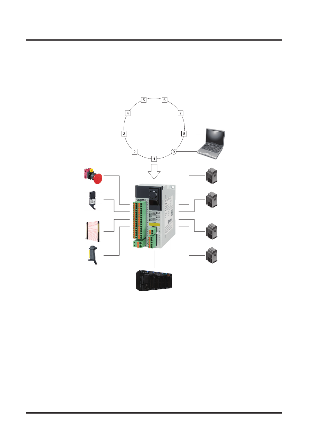
This device is a safety control unit. This device has eight built-in preset logics that can deal with
various safety systems. The logics can also be set (customizable logics).
The preset logics and customizable logics have acquired related international standards.
Selecting logics and connecting safety devices can construct various safety circuits.
Safety certied
Logic selection
• Fixed (1 to 8)
• Customization (0)
PC
Safety device
Monitor communication
(Non-safety)
SF-C21
PLC
Logic
setting
Contactor
(1) Selecting preset logics and connecting various safety devices
This device incorporates eight preset logics supporting basic applications and one customizable logic that can be set freely.
(2) Easy setting of software tool and customizable logic
Customizable logics can easily be set in PC by using a software tool.
(3) Acquisition of safety certication
This unit is a safety control unit that has acquired IEC 61508 (SIL3) and ISO 13849-1 (Up to
category 4, PLe).
(4) Safety categories 2, 3, and 4 available
Selecting logics and connecting various types of safety devices can construct systems available for Categories 2, 3, and 4 of ISO 13849-1.
© Panasonic Industrial Devices SUNX Co., Ltd. 201610
Page 11

Features
(5) Limiting of system space
More system space can be saved compared with a system using safety relay.
(6) Improvement of wiring work efciency
Adopting a removal terminal block can reduce man-hours for wiring and prevent improper
wiring when this device is replaced.
(7) Fail safe function
If a failure occur inside this device, the self-diagnosis function can detect the failure and turn
OFF the output.
(8) Enhancement of failure diagnosis
Failures, including those of safety devices in connection is diagnosed by using test pulse
(monitoring of cross short fault). In addition, self-diagnosis, e.g., memory diagnosis and circuit diagnosis, is performed.
(9) Installation according to use applications
35mm width DIN rail or M4 round head screw (length: 12mm or more) is available for installation.
© Panasonic Industrial Devices SUNX Co., Ltd. 2016 11
Page 12
Part Description
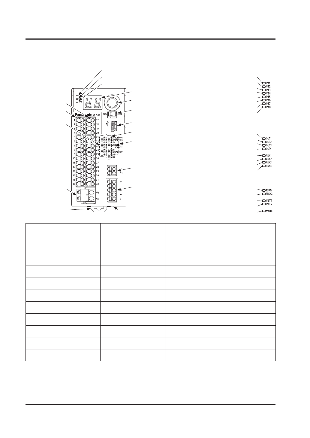
2-2 Part Description
Logic selection indicator (Orange)
Delay selection indicator (Orange)
Password selection indicator (Orange)
7-segment indicator (Red)
Terminal block for
I/O 2
Terminal block for
I/O 1
Indicator A
Terminal block for
external power
supply
DIN rail stopper
Indicator name Display Operation
Logic selection indicator (Orange) LOG
Delay selection indicator (Orange)
Password selection indicator
(Orange)
7-segment indicator (Red) -
Input 1 to 8 indicator (Orange)
Output 1 to 4 indicator (Green) OUT1, OUT2, OUT3, OUT4
Auxiliary output 1 to 4 indicator
(Orange)
Operation indicator (Green) RUN
Setting indicator (Orange) PROG
Interlock 1 / 2 indicator (Yellow) INT1, INT2
Muting indicator (Orange) MUTE
DEL
PAS
IN1, IN2, IN3, IN4, IN5, IN6,
IN7, IN8
AUX1, AUX2, AUX3, AUX4
Rotary switch
Mode selector switch
USB connector (miniB)
Indicator B
Indicator C
Terminal block for
internal power supply
Terminal block for RS-485
DIP switch for RS-485
[Indicator A]
Input 1 indicator (Orange)
Input 2 indicator (Orange)
Input 3 indicator (Orange)
Input 4 indicator (Orange)
Input 5 indicator (Orange)
Input 6 indicator (Orange)
Input 7 indicator (Orange)
Input 8 indicator (Orange)
[Indicator B]
Output 1 indicator (Green)
Output 2 indicator (Green)
Output 3 indicator (Green)
Output 4 indicator (Green)
Auxiliary output 1 indicator (Orange)
Auxiliary output 2 indicator (Orange)
Auxiliary output 3 indicator (Orange)
Auxiliary output 4 indicator (Orange)
[Indicator C]
Operation indicator (Green)
Setting indicator (Orange)
Interlock 1 indicator (Yellow)
Interlock 2 indicator (Yellow)
Muting indicator (Orange)
When logic is selected: lights up in orange
Other cases: turn OFF
When OFF delay is selected: lights up in orange
Other cases: turn OFF
When password is selected: lights up in orange
Other cases: turn OFF
Selected logic / OFF delay mode is displayed.
In lockout state, display of error is displayed.
Input at ON state: lights up in orange
When input turns OFF: turns OFF
When output at ON state: lights up in green
When output at OFF state: turns OFF
When output at ON state: lights up in orange
When output at OFF state: turns OFF
When normal operation is performed: lights up in green
When setting operation: turns OFF
When setting operation: lights up in orange
When normal operation: turns OFF
When interlock is effective: lights up in yellow
When interlock is ineffective: turns OFF
When output at ON state: lights up in orange
When output at OFF state: turns OFF
© Panasonic Industrial Devices SUNX Co., Ltd. 201612
Page 13
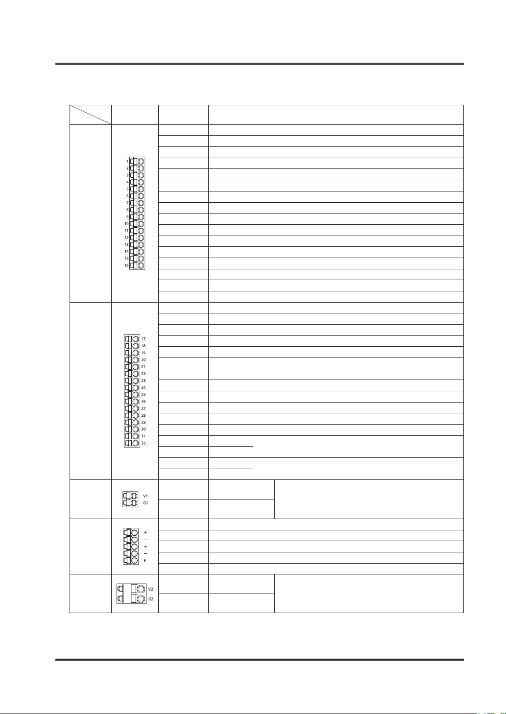
2-3 Terminal Arrangement
Terminal Arrangement
Terminal
dimensions
Terminal block for I/O 1
Terminal block for I/O 2
Terminal
block for in-
ternal power
supply
Terminal block
for RS-485
Terminal
block for ex-
ternal power
supply
Terminal No.
1 IN1 Safety input 1
2 T1 Safety input 1 / test output
3 IN2 Safety input 2
4 T2 Safety input 2 / test output
5 IN3 Safety input 3
6 T3 Safety input 3 / test output
7 IN4 Safety input 4
8 T4 Safety input 4 / test output
9 MUTE1 Muting indicator output 1_1
10 NC Not connected
11 INT11 Reset input 1 / test output
12 INT12 Reset input 1
13 AUX1 Auxiliary output 1
14 AUX2 Auxiliary output 2
15 AUX3 Auxiliary output 3
16 AUX4 Auxiliary output 4
17 IN5 Safety input 5
18 T5 Safety input 5 / test output
19 IN6 Safety input 6
20 T6 Safety input 6 / test output
21 IN7 Safety input 7
22 T7 Safety input 7 / test output
23 IN8 Safety input 8
24 T8 Safety input 8 / test output
25 MUTE2 Muting indicator output 1_2
26 NC Not connected
27 INT21 Reset input 2 / test output
28 INT22 Reset input 2
29 OUT1
30 OUT2
31 OUT3
32 OUT4
- V1 24V
- G1 0V
- + Transmission line (+)
- - Transmission line (−)
- + Transmission line (+)
- - Transmission line (−)
- E Terminal station setting
- V2 24V
- G2 0V
Terminal
name
Function
Control output 1
Control output 2
Power supply for safety input
Power supply for control output
Power supply for auxiliary output
When a device (such as light curtain) requiring power supply to inputs is connected, power is
supplied from internal power supply. This device does not operate when power is supplied from
external power supply.
© Panasonic Industrial Devices SUNX Co., Ltd. 2016 13
Page 14
Conrming Product Information
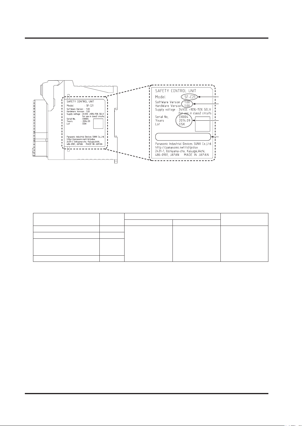
2-4 Conrming Product Information
The product information on this device can be conrmed on the nameplate on the side of the
product.
Model No.
Product version
Manufacturing
information
Standard mark of
conformity is shown.
2-4-1 Version-related Information
The versions of
SF-C21
software and software tool “
Congurator SF-C
” have been changed
due to addition / change of functions.
The added / changed functions are supported by the versions shown in the table below.
Function
Input lter Added
Dedicated exit muting Added
Sequential muting (Allowable
time difference in muting
input)
Logic display edit Added
Note: The setting range has been changed. The setting range in Ver. 1.00 is the same as that for parallel muting.
Added /
changed
Changed
(Note)
SF-C21
Ver. 2.00 and newer Ver. 2.00 and newer
Compatible version
software
Congurator SF-C
Remarks
Settings cannot be
made unless the
function is supported
by both software versions.
© Panasonic Industrial Devices SUNX Co., Ltd. 201614
Page 15
2-5 Mounting
WARNING
● Do not touch the terminals while power is turned ON. Doing so may cause an electric shock.
● Be careful to prevent entry of foreign materials, such as chip and wire scrap into this device.
Otherwise, this could cause re, failure or malfunction.
● Do not disassemble or modify this device. Doing so could cause failure, malfunction, injury, or
re. When this device is repaired or modied by other than us, this device will not be covered by
our guarantee.
CAUTION
● Do not touch the conductive parts of this device directly. Doing so could cause malfunction or
failure of this device.
● Do not drop or apply strong impact on the case of this device, which is made of resin.
Doing so could cause damage to it.
● Fix this device with the DIN rail or screws securely.
● Install this device on a at surface.
Installing it on an uneven surface applies excessive force to internal parts, resulting in a failure.
● In case of disposal, dispose this device as an industrial waste.
2-5-1 Installing Direction
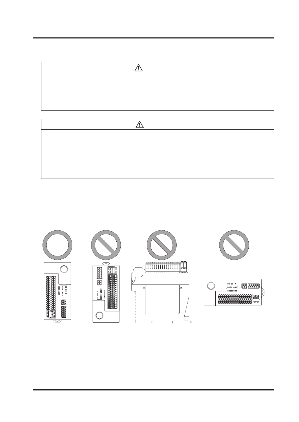
Mounting
When installing this device, make sure that it is correctly oriented. The device must be installed
vertically with its indicators and terminal blocks facing the operator side in order to ensure heat
dissipation.
Installed in vertically
reversed orientation
Horizontally installed Sideways installed
© Panasonic Industrial Devices SUNX Co., Ltd. 2016 15
Page 16
Mounting
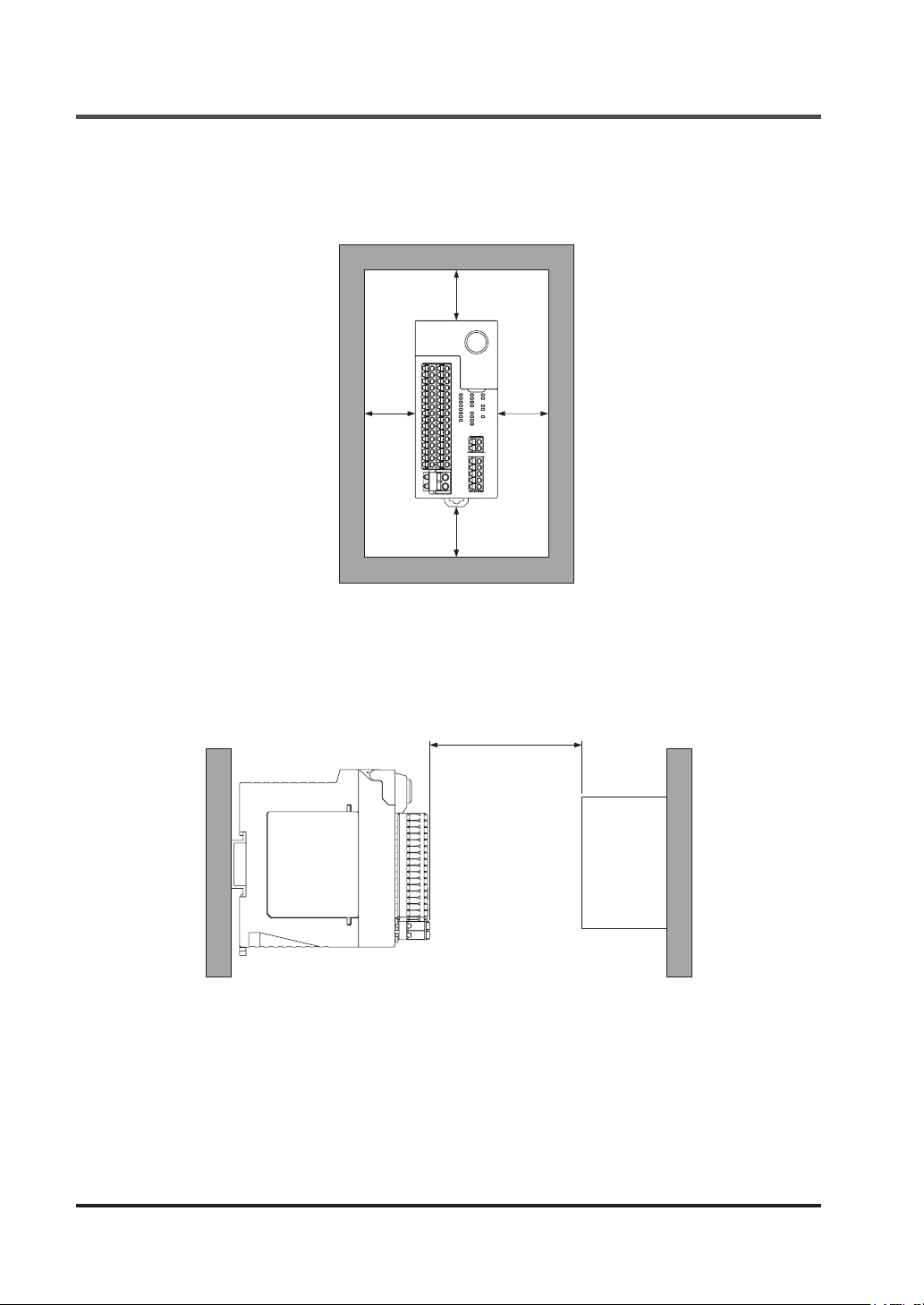
2-5-2 Installation Space
In addition, make sure that the device's upper, lower, left, and right surfaces are spaced by
50mm or more from surrounding objects such as other devices and wiring ducts.
50mm or more
50mm
or more
50mm
or more
50mm or more
Do not install the unit above devices which generate heat such as heaters, transformers or large
scale resistors.
In order to eliminate any effects from noise emission, power wires and electromagnetic devices
should be kept at 100mm or more away from the surfaces of the device. When installing the unit
behind the doors of the control board, be especially careful to secure clearances as above.
100mm or more
SF-C21 Other devices
© Panasonic Industrial Devices SUNX Co., Ltd. 201616
Page 17
Mounting
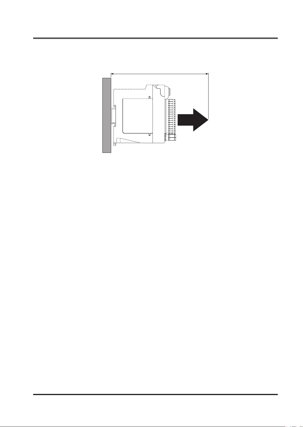
To connect the software tool and cables, keep a space of 170mm or more away from the installation surface of this device.
170mm or more
SF-C21
© Panasonic Industrial Devices SUNX Co., Ltd. 2016 17
Page 18
Mounting
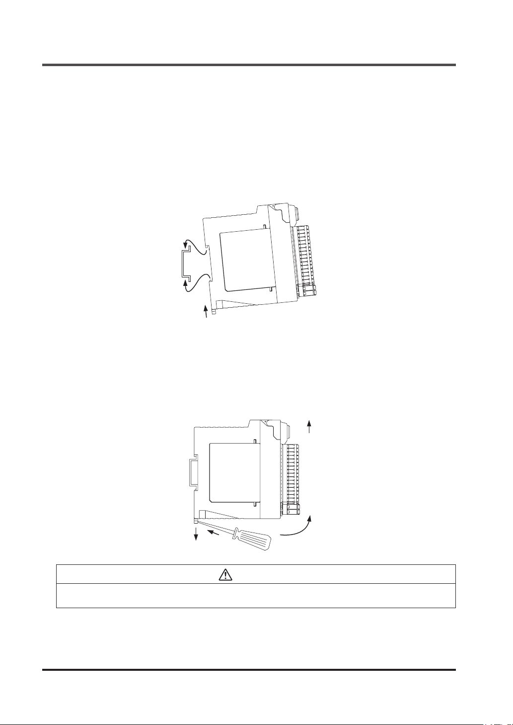
2-5-3 Installation to and Removal from a DIN Rail
Compatible DIN rail models (based on JIS C 2812)
- TH35-7.5Al or TH35-7.5Fe
<Installing>
Step 1 Press in the DIN rail stopper.
Step 2 Fit the nail on the opposite side of the DIN rail stopper with the DIN rail.
Step 3 Fit the DIN rail stopper side of the unit with the DIN rail by pressing it in.
2
3
1
<Removing>
Step 1 Insert the at-head screwdriver into the groove in the DIN rail stopper.
Step 2 Draw out the DIN rail stopper.
Step 3 Push up the control unit toward the opposite side of the DIN rail stopper.
Step 4 Remove the control unit by pulling its lower side while maintaining it in the pushed-up
position (step 3).
3
2
1
4
CAUTION
Do not attempt to pull the control unit without rst drawing out the DIN rail stopper or the nail will
break.
© Panasonic Industrial Devices SUNX Co., Ltd. 201618
Page 19
Mounting
2-5-4 Installing the Unit Directly in a Control Panel Using Screws
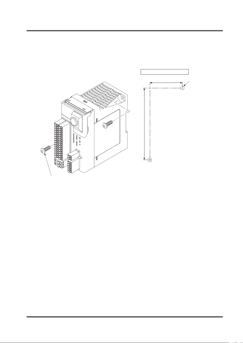
The unit can be installed directly in a control panel by means of M4 pan head screws (length:
12mm or more) (purchase separately). The machine screws should be tightened with a torque
of 1.2N•m or less.
Mounting hole nished size (Unit: mm)
37
82
M4
M4 pan head screws (length: 12mm or more)
2-5-5 Installation Environment
For the installation environment, refer to “
Use the unit as per its specications.
● Installation place: The unit is designed for use in a control panel.
● Ambient temperature: -10 to +55°C
● Ambient humidity: 30 to 85% RH (No dew condensation)
● Pollution degree: 2
● Overvoltage category: II or lower
● Usable altitude: 2,000m above sea level or lower
8-1 Specications
.”
© Panasonic Industrial Devices SUNX Co., Ltd. 2016 19
Page 20
Wiring
2-6 Wiring
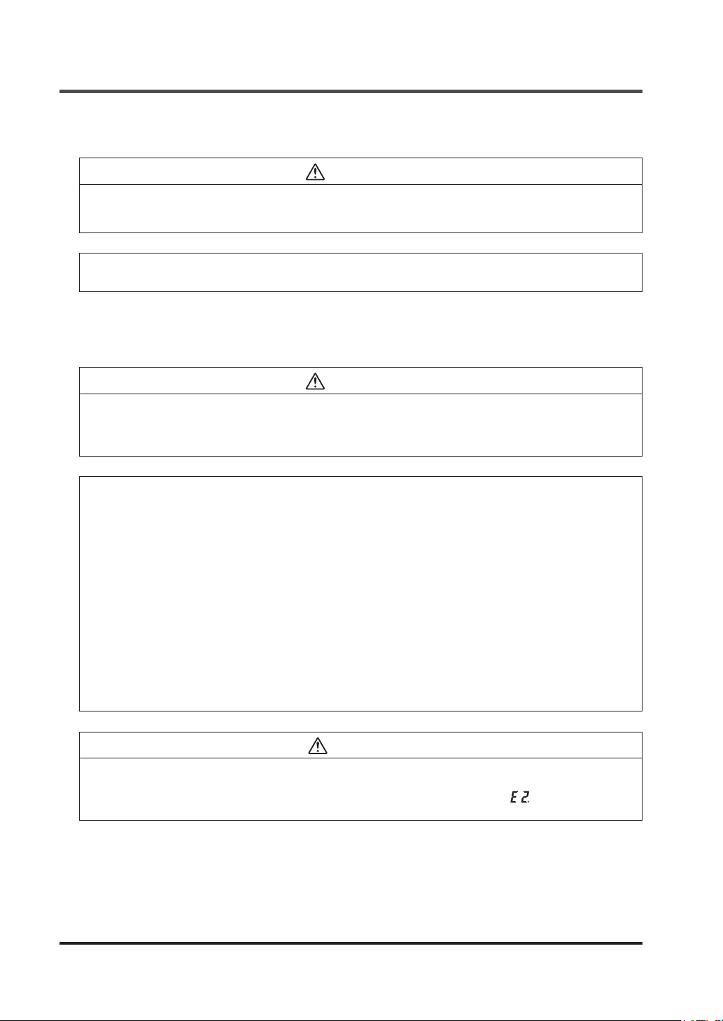
WARNING
Take countermeasure against the system to be applied for this device so as not to carry out the
dangerous performance caused by the earth failure.
Failure to do so could cause invalid for the system stop, resulting in death or serious injury.
<Reference>
Use a safety relay unit or an equivalent control circuit in safety for control output 1 / 2.
2-6-1 Power Supply Unit
WARNING
Wire correctly using a power supply unit which conforms to the laws and standards of the region
where this device is to be used.
If the power supply unit is non-conforming or the wiring is improper, it can cause damage or
malunction of this device.
<Reference>
A specialist who has the required electrical knowledge should perform the wiring.
The power supply unit must satisfy the conditions given below.
1) Power supply unit authorized in the region where this device is to be used.
2) Power supply unit SELV (safety extra low voltage) / PELV (protected extra low voltage)
conforming to EMC Directive and Low-voltage Directive (In case CE Marking conformity
is required.)
3) Power supply unit conforming to the Low-voltage Directive and with an output of 100VA
or less.
4) The frame ground (F.G.) terminal must be connected to ground when using a commercially available switching regulator.
5) Power supply unit with an output holding time of 20ms or more.
6) In case a surge is generated, take countermeasures such as connecting a surge absorber to the origin of the surge.
7) Power supply unit corresponding to CLASS 2 (In case CTÜVUS Mark conformity is required.)
CAUTION
When turning ON the power supply to this device, turn ON the external power supply within 30
sec. after the internal power supply is turned ON, or turn ON the external power supply rst. Delay
in power ON to the external power supply locks out this device, displaying “ ” in the 7-segment
indicator (red).
© Panasonic Industrial Devices SUNX Co., Ltd. 201620
Page 21
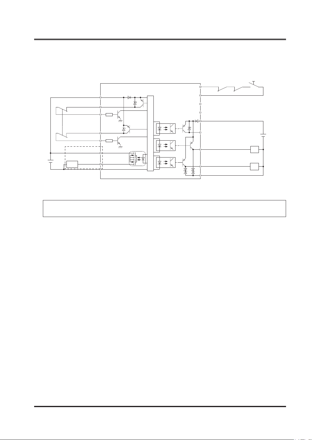
2-6-2 I/O Circuit Diagrams
<Example: In case of using manual reset mode and external device monitor>
Wiring
INT11
KA
KB
V1
T1 (3, 5, 7)
IN1 (3, 5, 7)
4.7kΩ
T2 (4, 6, 8)
IN2 (4, 6, 8)
*1
MUTE1
+
−
*1: Wired when muting function and override function are used.
Load
MUTE2
4.7kΩ
G1
Main circuit
INT12
INT21
INT22
V2
AUX1, 2, 3, 4
OUT1(3)
OUT2(4)
G2
<Reference>
KA, KB: External device (Forced guided relay, magnetic contactor, monitored valve, etc.)
Reset
+
−
KA
KB
© Panasonic Industrial Devices SUNX Co., Ltd. 2016 21
Page 22
Wiring
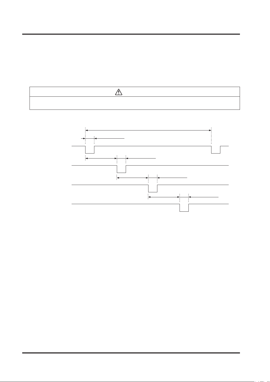
<Output waveform [control output ON]>
When control output is turned ON, this device performs self-diagnosis of the output circuit.
The output is turned into OFF status periodically. (Refer to the gure below.)
When the OFF signal is fed back, this device judges the output circuit as normal.
When the OFF signal is not fed back, this device judges either the output circuit or wiring as error, and the control output maintains OFF status.
CAUTION
Perform the wiring with paying attention to the input response time of the machine to be connected to this device, since the OFF signal of this device might cause malfunction.
<Timing chart>
Approx. 18ms
Approx. 200μs
Control output 1
(OUT1)
Control output 1
(OUT2)
Control output 2
(OUT3)
Control output 2
(OUT4)
ON
OFF
ON
OFF
ON
OFF
ON
OFF
Approx. 4.5ms
Approx. 200μs
Approx. 4.5ms
Approx. 200μs
Approx. 4.5ms
Approx. 200μs
© Panasonic Industrial Devices SUNX Co., Ltd. 201622
Page 23
Wiring
2-6-3 Connecting to the Terminal Block
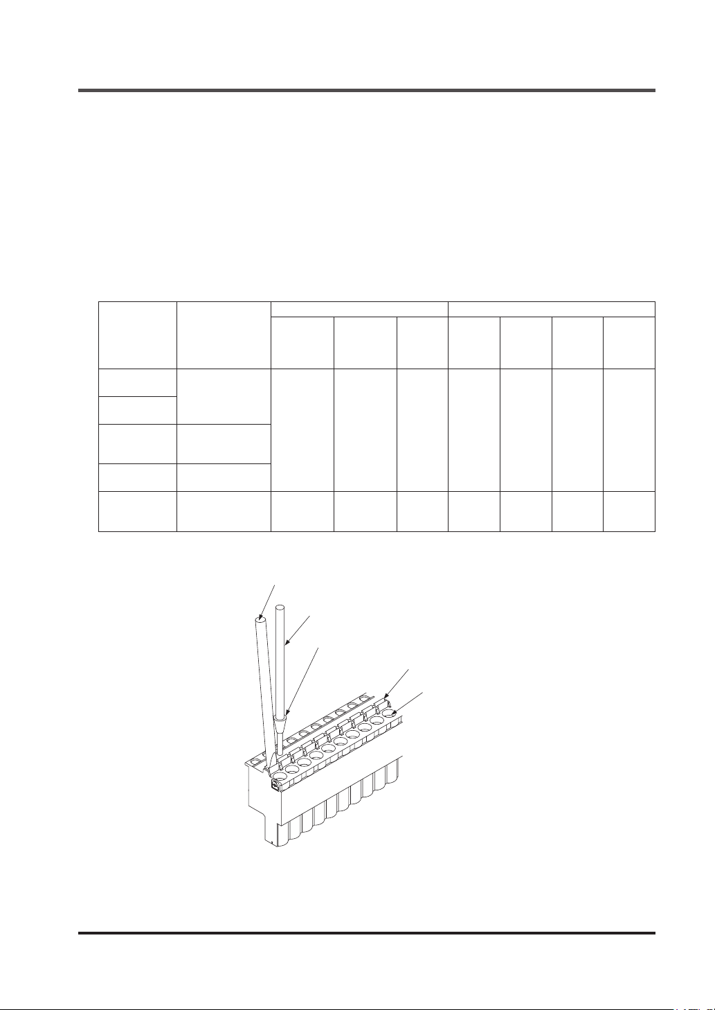
● When connecting to the terminal block, insert a solid wire or a twisted wire (lead wire) with a
ferrule (rod) terminal, as shown in the gure below, into the hole till it stops. (Ferrule terminals
are not included in the product package.)
● The wire is locked when it is properly inserted. However, do not to pull the wire with an ex-
cessive force or the cable may break.
● When connecting a twisted wire (lead wire) without using a ferrule terminal, insert the wire to
the innermost of the connecting hole while pressing the release button.
● To remove the wire, draw it out while pressing the release button.
For a solid wire or a twisted wire (lead wire) to be used, refer to the table below.
Ferrule terminal Solid wire / twisted wire
Terminal block
name
Terminal block
for I/O 1
Terminal block
for I/O 2
Terminal block
for internal
power supply
Terminal block
for RS-485
Terminal block
for external
power supply
<Terminal block> Manufactured by Phoenix Contact
Terminal block
model No.
FMC 1,5/16-ST-3,5
FMC 1,5/2-ST-3,5
FMC 1,5/5-ST-3,5
FKC 2,5/2-ST 0.25-2.5 0.25-2.5 10 0.2-2.5 0.2-2.5 24-12 10
With an insulation sleeve
(mm2)
0.25-0.75 0.25-1.5 10 0.2-1.0 0.2-1.5 24-16 10
Without an
insulation
sleeve
(mm2)
Terminal
length
(mm)
Solid wire
(mm2)
Twisted
wire
(mm2)
AWG
Stripped
wire length
(mm)
Flat-head screwdriver
Lead wire
Ferrule terminal
Release button
Insertion hole
© Panasonic Industrial Devices SUNX Co., Ltd. 2016 23
Page 24

Wiring
2-6-4 Connection of Safety Devices
When wiring between this device and safety devices, perform the following two points at this
device to make the wiring satisfy the conditions dened in category 3 or 4.
● Duplication of I/O wires
● Implementation of self-diagnosis function (using test pulse) (excluding semiconductor output
devices such as light curtain)
The functions (input, output, auxiliary output, and reset) of this device are automatically set by
selecting preset logic.
Customizable logic can be created by changing preset logic in part or in whole by using the
software tool. Arbitrary logics, independent of preset logic, can also be created as customizable
logics.
<Reference>
Logics changed by the software tool or arbitrary logics created cannot be transferred to this device
if their safety cannot be retained.
© Panasonic Industrial Devices SUNX Co., Ltd. 201624
Page 25
Chapter 3 Functions
3-1 Safety Input
This device incorporates eight safety inputs. Safety inputs are comprised of four (duplex) input
blocks.
● Input block 1: IN1 / IN2
● Input block 2: IN3 / IN4
● Input block 3: IN5 / IN6
● Input block 4: IN7 / IN8
The following diagnoses are carried out by setting input blocks:
Setting With / without diagnosis (method)
2NC contact input
PNP semiconductor input
1NO / 1NC contact input
1NC contact input Without diagnosis
Devices as shown below can be connected.
● 2NC, 1NO / 1NC, or 1NC contact output type switch
● PNP transistor output sensor or switch
With diagnosis (The input devices connected to this device are diagnosed to
detect earth fault, short fault to +V, or cross short fault.)
Without diagnosis (The input devices themselves, connected to this device,
detect earth fault, short fault to +V, or cross short fault for their own outputs.)
With diagnosis (The input devices connected to this device are diagnosed to
detect earth fault, short fault to +V, or cross short fault.)
<Major connectable devices>
● Emergency stop switch
● Door switch (including non-contact type)
● Light curtain
● Laser scanner
● Two-hand operation switch
● Enable switch
● Key selector switch
3-1-1 Contact Input Mismatch Allowable Time
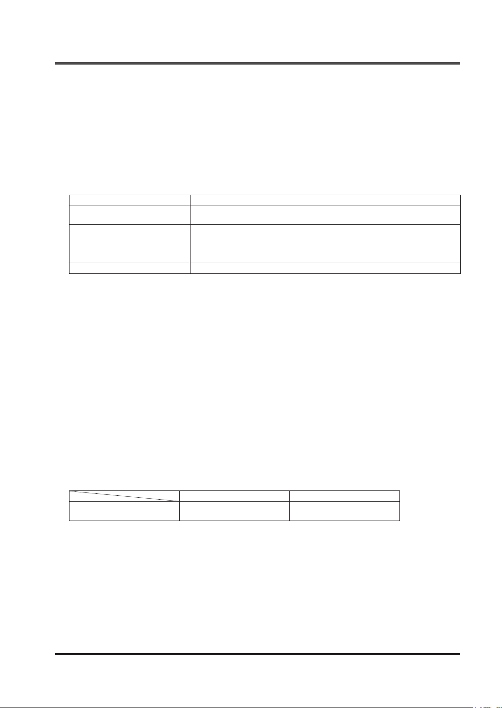
If the safety input is 2NC or 1NO / 1NC, this device simultaneously monitors ON side of two
safety inputs of one system (“closed” status in the case of door switch). OFF side (“open” status
in the case of door switch) cannot be monitored.
Settable range Initial setting
Input mismatch allowable time
0 (unlimited) to 60 sec.
(in units of 0.1 sec.)
1 sec.
© Panasonic Industrial Devices SUNX Co., Ltd. 2016 25
Page 26

Functions
3-2 Control Output
This device is equipped with two independent systems (4 outputs = 2 systems × duplication) for
control outputs (PNP semiconductor outputs).
● Control output 1: OUT1 / OUT2
● Control output 2: OUT3 / OUT4
• When safe: ON status
• When not safe / When locked out: OFF status
In the same system, two outputs perform the same operation.
3-2-1 Response Time
The maximum response time of this device is as follows:
● OFF response (ON status → OFF status): 10ms or less
● ON response (OFF status → ON status): 100ms or less
3-3 Auxiliary Output
This device is equipped with four auxiliary outputs as non-safety monitor outputs. In the case of
selecting preset logic, the setting is as follows:
AUX1 Negative logic of OUT1 / OUT2
AUX2 Negative logic of OUT3 / OUT4
AUX3 Reset trigger output
AUX4 Lockout output
Each auxiliary output operation can be changed to the following output operation by using the
software tool.
For details, refer to “
● Positive logic output or negative logic output of OUT1 / OUT2
● Positive logic output or negative logic output of OUT3 / OUT4
● Output A / B / C / D of diagnosis results of input block 1 / 2 / 3 / 4
● Output E / F / G of diagnosis results of internal logical circuit
● Reset trigger output
● Lockout output
● Muting indicator output
● Monitor output of IN1 to 8
● Normally OFF
Chapter 5 Software Tool
.”
© Panasonic Industrial Devices SUNX Co., Ltd. 201626
Page 27
Functions
3-4 Interlock (Reset)
CAUTION
When the safety input condition of this device is satised, the control outputs turned into ON status in the case of auto reset setting. To prevent unexpected startup of the machine, secure safety
for the overall system.
The reset function of this device is set by selection of preset logic and wiring.
The software tool is available for selecting the overall reset or partial reset. For partial reset,
manual reset or auto reset is selectable.
3-4-1 Overall Reset
Overall reset: preset logic No.1, 2, 3, 6, 7, and 8
The outputs of two systems of this device are reset by one operation.
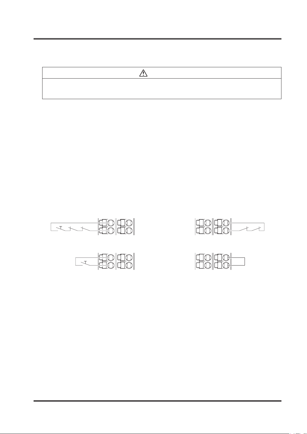
● Manual reset : Momentary type switch is connected to between INT11 and INT12.
Resetting operation can be performed by switching the switch contact from
“Close” to “Open.”
● Auto reset : INT21-INT22 is short-circuited.
If between INT21 and INT22 is not short-circuited when power is turned ON, manual reset is
automatically selected.
<Overall reset (manual start)>
INT11
INT12
With external device monitor
INT11
INT12
Without external device monitor
INT21
INT22
INT21
INT22
<Overall reset (auto start)>
INT11
INT12
With external device monitor
INT11
INT12
Without external device monitor
INT21
INT22
INT21
INT22
© Panasonic Industrial Devices SUNX Co., Ltd. 2016 27
Page 28
Functions
3-4-2 Partial Reset
Partial reset: Preset logic Nos. 4 and 5
Each of the outputs of two systems of this device is reset individually.
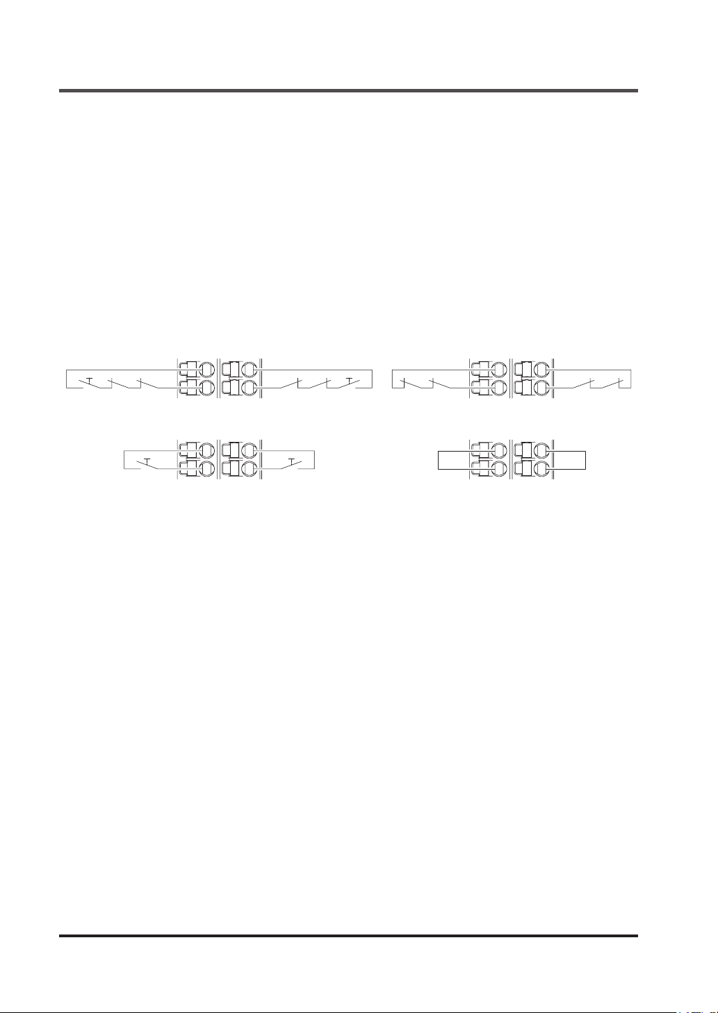
At three time of partial reset, INT11-INT12 and INT21-INT22 function are reset terminal for output control 1 (OUT1 / 2) and reset terminal for output control 2 (OUT3 / 4), respectively.
The Preset logic of this device sets manual reset. Change to auto reset can be made using software tool.
● Manual reset : Momentary type switch is connected to between INT11 and INT12 and be-
tween INT21 and INT22. Resetting operation can be performed by switching
the switch contact from Close to Open.
● Auto reset : Short-circuit is made between INT11 and INT12 and between INT21 and
INT22.
<Partial reset (manual start)>
INT11 INT21
INT12 INT22
With external device monitor
INT11 INT21
INT12 INT22
Without external device monitor
<Partial reset (auto start)>
INT11 INT21
INT12 INT22
With external device monitor
INT11 INT21
INT12 INT22
Without external device monitor
© Panasonic Industrial Devices SUNX Co., Ltd. 201628
Page 29
Functions
3-5 Releasing Lockout
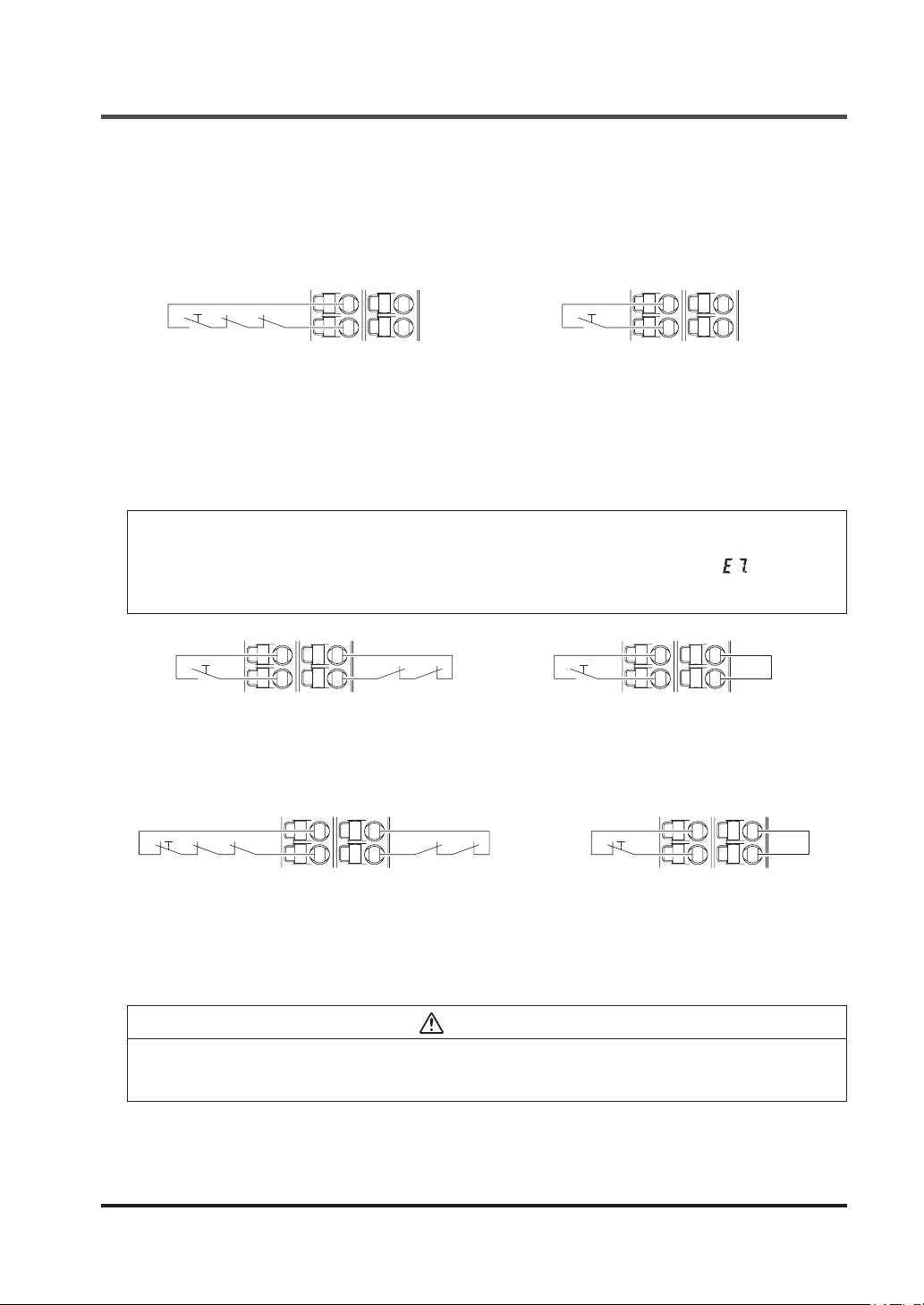
Lockout is always released after source of error has been removed.
Lockout is released by manually operating the switch connected to between INT11 and INT12.
● Overall reset (manual start) : The reset switch functions as a lockout release switch.
Switching the switch from “Close” to “Open” can release lockout.
INT11
INT12
With external device monitor
INT21
INT22
INT11
INT12
Without external device monitor
INT21
INT22
● Overall reset (auto start) : Momentary type switch is connected to between INT11 and
INT12.
When this device is put in lockout status, the switch functions as
a lockout release switch.
Switching the switch from “Close” to “Open” can release lockout.
<Reference>
When INT11-INT12 and INT21-INT22 are simultaneously “Closed” during overall reset (auto
start), “Reset input circuit error” turns this device into lockout status. In this case, “ ” appears in
7-segment indicator (red).
In this case, release lockout by operating the switch again to switch “Close” to “Open.”
INT11 INT21
INT12 INT22
With external device monitor
INT11 INT21
INT12 INT22
Without external device monitor
● Partial reset (auto start) : Alternate type switch is connected to between INT11 and INT12.
Switching “from Open to Close to Open” can release lockout.
After the release of lockout, set the switch to “Close.”
INT11 INT21
INT12 INT22
With external device monitor
INT11 INT21
INT12 INT22
Without external device monitor
After the release of lockout, the operation is performed as follows:
● Manual reset : Manual reset turns the control output into ON status.
● Auto reset : Auto reset turns the control output into ON status.
CAUTION
When the safety input condition of this device is satised, release of lockout turns the control output into ON status in the case of auto reset setting. To prevent unexpected startup of the machine,
secure safety for the overall system.
© Panasonic Industrial Devices SUNX Co., Ltd. 2016 29
Page 30
Functions
3-6 External Device Monitor
Operation status of the external devices connected to the control output of this device is monitored.
The NC contacts of the external devices are connected in series between INT11 and INT12 and
between INT21 and INT22.
Refer to “
3-4 Interlock (Reset)
3-5 Releasing Lockout
” and “
”.
3-7 Test Input
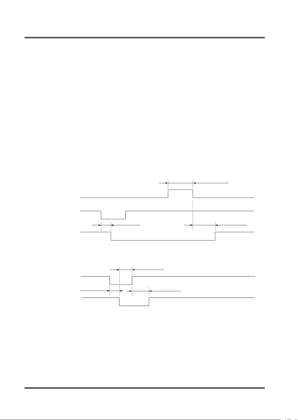
This is used for “Check” required in control category 2 of ISO 13849-1.
When test input is effective, the control output is turned into OFF status.
This function is not incorporated into preset logic. This function is used for setting with the software tool. Refer to “
The switch for 1NC contact or PNP semiconductor output (normally set to ON) is connected.
● Contact “Close” or output ON : Test input invalid
● Contact “Open” or output OFF : Test input valid
<Manual reset>
Reset
Closed
5-11-1 Types of Inputs
Open
”.
150ms to 4 sec.
Test input
Control output
1 / 2
<Auto reset>
Test input
Control output
1 / 2
Closed
Open
ON
OFF
Closed
Open
ON
OFF
10ms or less
10ms or less 100ms or less
10ms or more
100ms or less
© Panasonic Industrial Devices SUNX Co., Ltd. 201630
Page 31
Functions
3-8 MODBUS Communication (Non-safety)
WARNING
Communication information is not available for safety control.
Using MODBUS RTU protocol, PLC, etc., can obtain monitor information (safety input status,
control output status, error information, error description, and error log) from this device.
Master station (PLC, etc.) issues a command (command message) to the slave station (this device), and the slave station makes a response (response message) according to the command.
For this device, up to eight units can be connected as slave stations.
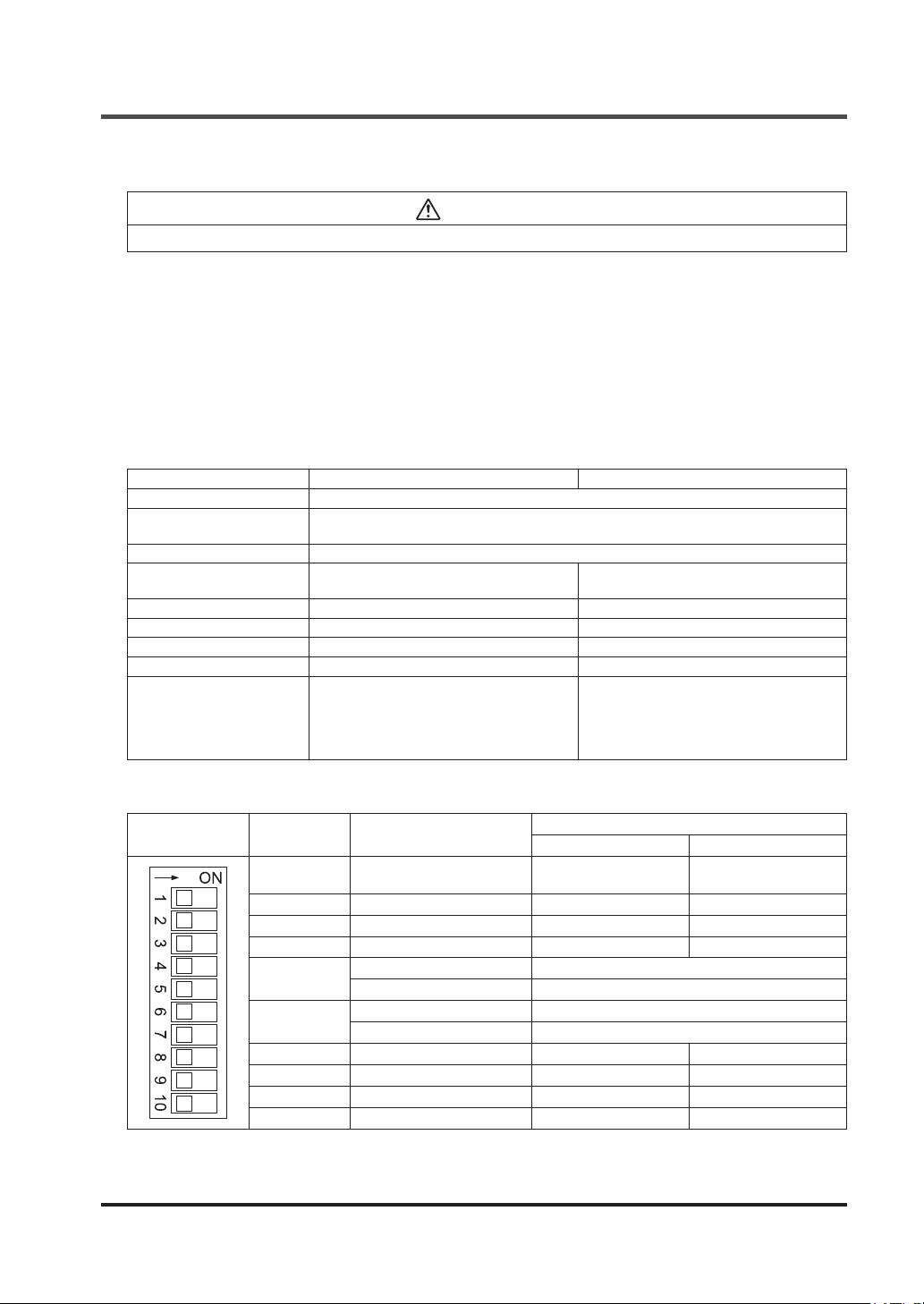
The communication settings are congured by using DIP switches for RS-485 on the bottom of
this device or software tool.
3-8-1 MODBUS RTU Specication
Item Setting range Factory default
Interface RS-485
Maximum transmission
distance
Data length 8 bits
Communication preference
setting
Parity bit presence With or without With
Parity bit type Odd / even Odd
Stop bit 1 bit / 2 bits 1 bit
Communication address 1 to 247 1
Baud rate
Either DIP switches take or software tool
takes precedence
9,600 bps
19,200 bps
38,400 bps
57,600 bps
115,200 bps
100m
DIP switches take precedence
9,600 bps
Settings by DIP switches for RS-485 (all OFF at factory setting)
DIP switches
DIP switches
No.
1
2 Parity bit presence With Without
3 Parity bit type Odd Even
4 Stop bit 1 2
5
6
7 Baud rate 9,600 bps 19,200 bps
8 Unused - -
9 Unused - -
10 Unused - -
Setting item
Communication preference
setting
Communication address 1 SW5: OFF, SW6: OFF
Communication address 2 SW5: ON, SW6: OFF
Communication address 3 SW5: OFF, SW6: ON
Communication address 4 SW5: ON, SW6: ON
OFF ON
DIP switches take
precedence
© Panasonic Industrial Devices SUNX Co., Ltd. 2016 31
Input status
Software tool takes
precedence
Page 32
Functions
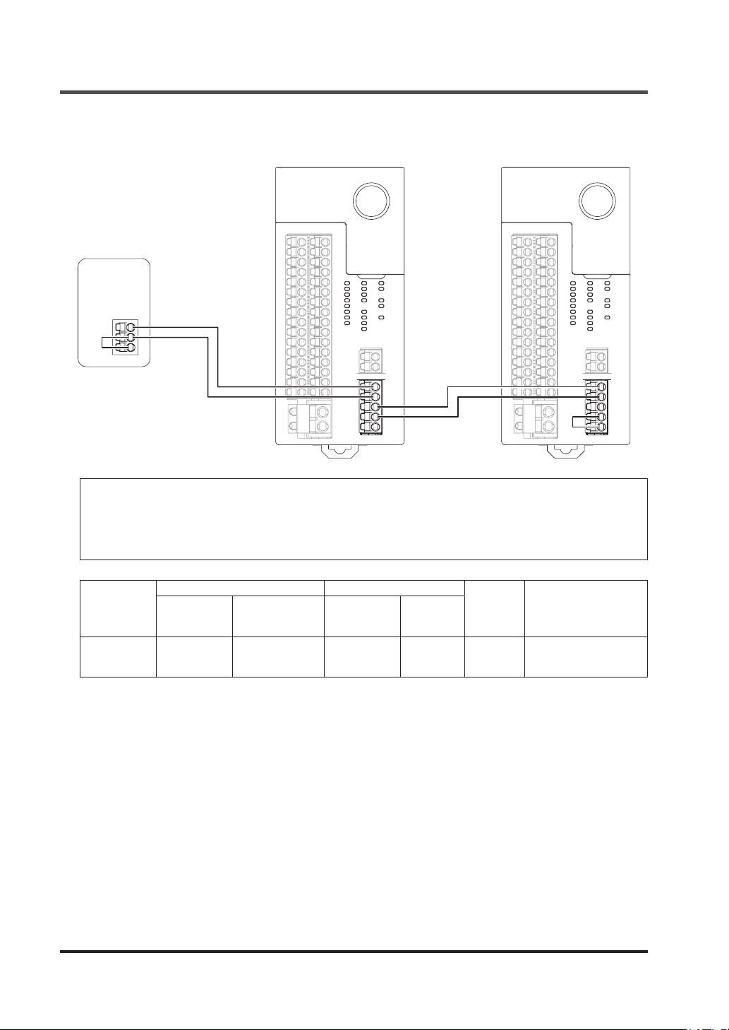
3-8-2 Wiring Example
MODBUS
RTU master
E
SF-C21
+
-
+ +
+
-
-
E
SF-C21
-
-
E
<Reference>
● When the device is used as a terminal station, short-circuit the - terminal and E terminal
● Use shielded twisted pair cables.
● The transmission line cables (shielded cables) should be connected in a crossover fashion and
grounded at one end.
+
Classication
Shielded
twisted pair
Conductor Insulator
Size
2
0.5 mm
(AWG 20) or
more
Resistance
value
(At 20°C)
Up to 33.4 Ω/km Polyethylene Up to 0.5
Material
Thickness
(mm)
© Panasonic Industrial Devices SUNX Co., Ltd. 201632
Cable
diameter
(mm)
Approx.
7.8
Applicable cable
example
Hitachi Cable, Ltd.
KPEV-S0.5 mm2×1P
Belden Inc. 9207
Page 33
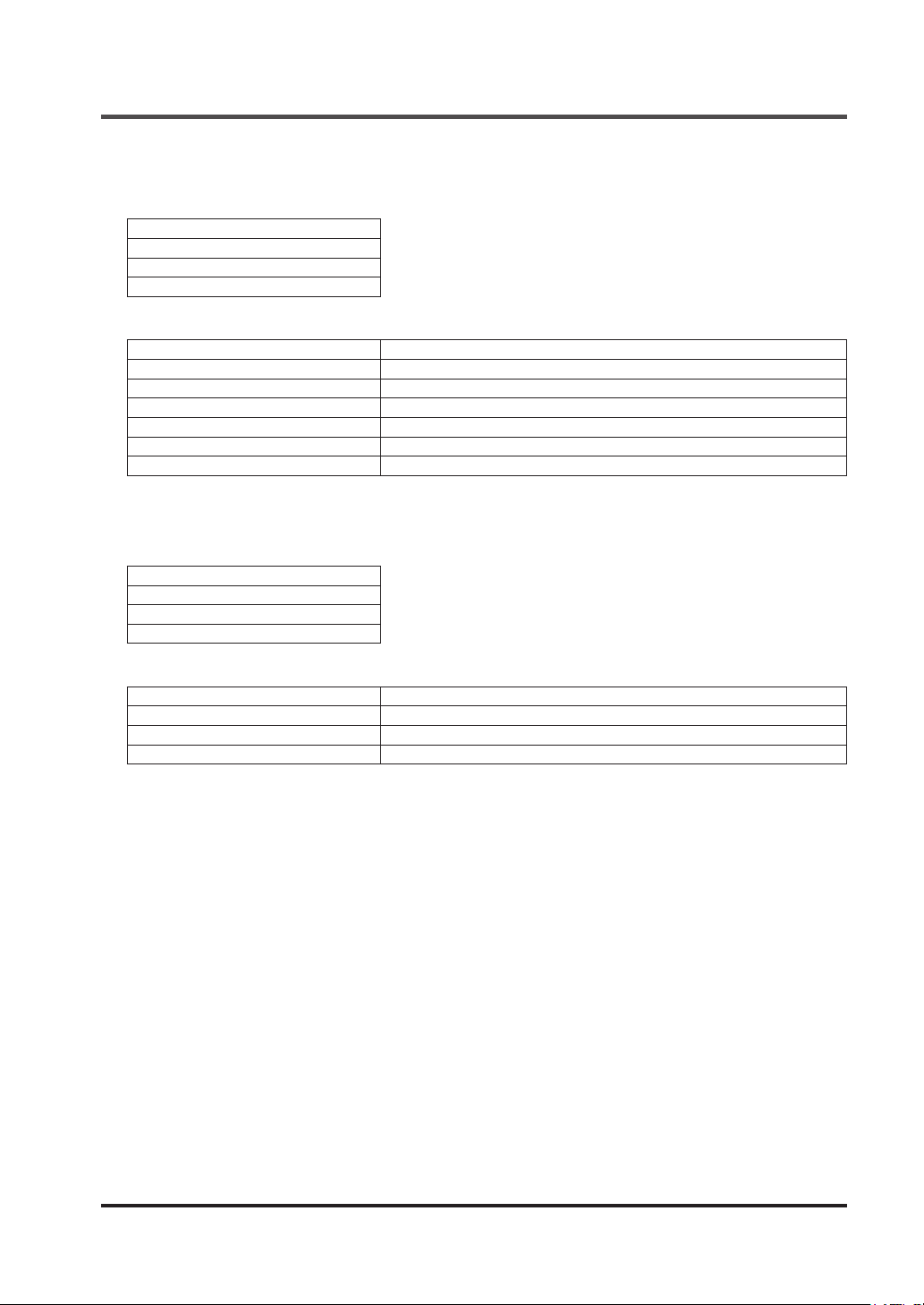
3-8-3 Function Code
Conguration of communication data
Ofce No.
Function code
Data
CRC-16
Function code
Function code Function
0x01 Reading coil (output) status
0x02 Reading relay (input) status
0x03 Reading holding register
0x81 Error in reading coil (output) status
0x82 Error in reading relay (input) status
0x83 Error in reading holding register
3-8-4 Error Codes
Conguration of communication data
Ofce No.
Function code
Error code
CRC-16
Functions
Error code
Error code Description
0x01 Function code error
0x02 Address error
0x03 Data quantity error
© Panasonic Industrial Devices SUNX Co., Ltd. 2016 33
Page 34
Functions
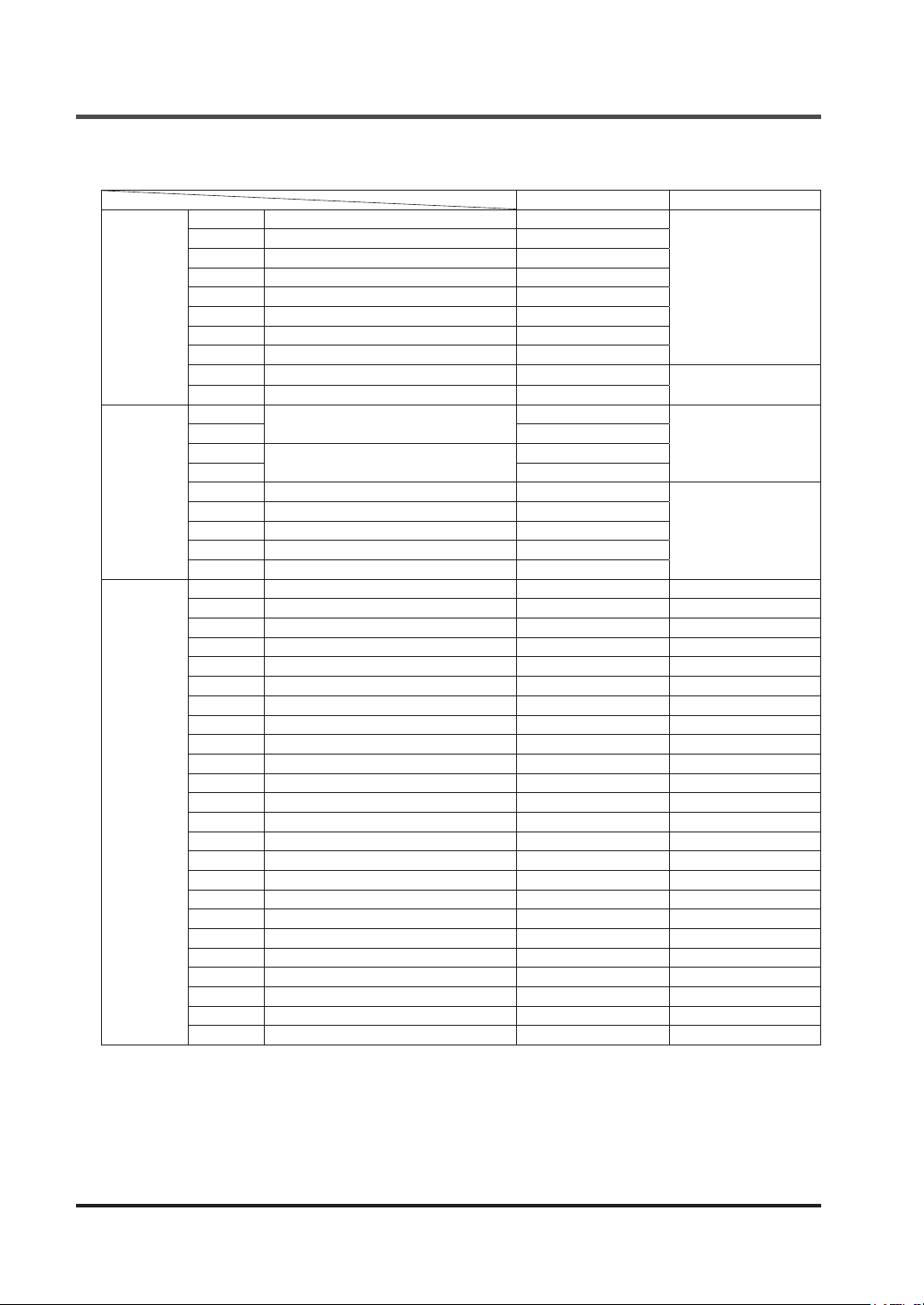
3-8-5 Address Map
IN1 Safety input 1 0x0000
IN2 Safety input 2 0x0001
IN3 Safety input 3 0x0002
IN4 Safety input 4 0x0003
Input
Output
Holding
register
IN5 Safety input 5 0x0004
IN6 Safety input 6 0x0005
IN7 Safety input 7 0x0006
IN8 Safety input 8 0x0007
INT1 Reset input 1 0x0010
INT2 Reset input 2 0x0011
OUT1
OUT2 0x1001
OUT3
OUT4 0x1003
AUX1 Auxiliary output 1 0x1010
AUX2 Auxiliary output 2 0x1011
AUX3 Auxiliary output 3 0x1012
AUX4 Auxiliary output 4 0x1013
MUTE Muting indicator output 0x1014
IN1/2 Input block 1
IN3/4 Input block 2
IN5/6 Input block 3
IN7/8 Input block 4
LOGIC1 Control block 1
LOGIC2 Control block 2
LOGIC3 Control block 3
ER1 Lockout history (Latest)
ER2 Lockout history (1 save ago)
ER3 Lockout history (2 saves ago)
ER4 Lockout history (3 saves ago)
ER5 Lockout history (4 saves ago)
LR1 Logic No. history (Latest)
LR2 Logic No. history (1 save ago)
LR3 Logic No. history (2 saves ago)
LR4 Logic No. history (3 saves ago)
LR5 Logic No. history (4 saves ago)
DR1 OFF delay No. history (Latest)
DR2 OFF delay No. history (1 save ago)
DR3 OFF delay No. history (2 saves ago)
DR4 OFF delay No. history (3 saves ago)
DR5 OFF delay No. history (4 saves ago)
RRQ Reset request status
MUT Muting condition satisfaction status
Control output 1
Control output 2
Bit address Word address
0x0000
0x0001
0x1000
0x1002
-
-
-
-
-
-
-
-
-
-
-
-
-
-
-
-
-
-
-
-
-
-
-
-
0x0100
0x0101
0x1000
0x1001
0x1002
0x1003
0x1100
0x1101
0x1102
0x1200
0x1201
0x1202
0x1203
0x1204
0x1300
0x1301
0x1302
0x1303
0x1304
0x1400
0x1401
0x1402
0x1403
0x1404
0x2000
0x2001
© Panasonic Industrial Devices SUNX Co., Ltd. 201634
Page 35
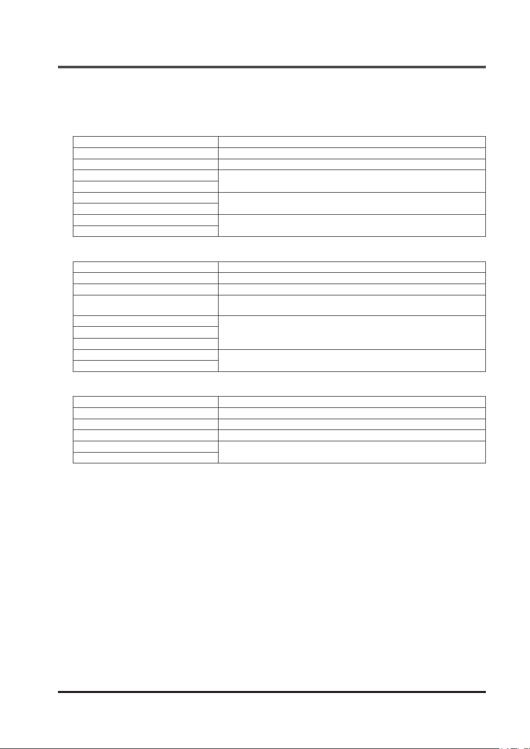
3-8-6 Message Format
Function code: 0x01
●
<Command>
Data Description
Ofce No.
Function code 0x01
Reading start address (H)
Reading start address (L)
Read number (H)
Read number (L)
CRC-16 (H)
CRC-16 (L)
<Response during normal operation>
Data Description
Ofce No.
Function code 0x01
Number of bytes of communication
data
Data 1 to be read
…
Data n to be read
CRC-16 (H)
CRC-16 (L)
SF-C21
Bit address to read data from
Quantity of data to be read
Message error judgment data
SF-C21
Number of bytes of communication data
Data to be read
Message error judgment data
Functions
equipment address
equipment address
<Response during abnormal operation>
Data Description
Ofce No.
Function code 0x81
Error code Error code
CRC-16 (H)
CRC-16 (L)
SF-C21
Message error judgment data
equipment address
© Panasonic Industrial Devices SUNX Co., Ltd. 2016 35
Page 36
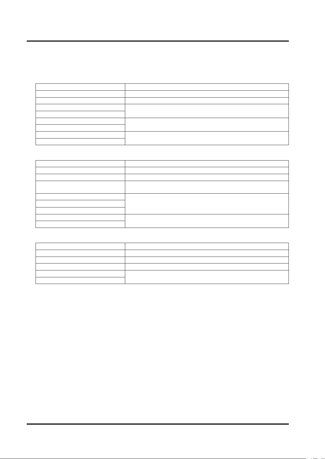
Functions
3-8-7 Function Code
Function code: 0x02
●
<Command>
Data Description
Ofce No.
Function code 0x02
Reading start address (H)
Reading start address (L)
Read number (H)
Read number (L)
CRC-16 (H)
CRC-16 (L)
<Response during normal operation>
Data Description
Ofce No.
Function code 0x02
Number of bytes of communication
data
Data 1 to be read
…
Data n to be read
CRC-16 (H)
CRC-16 (L)
SF-C21
Bit address to read data from
Quantity of data to be read
Message error judgment data
SF-C21
Number of bytes of communication data
Data to be read
Message error judgment data
equipment address
equipment address
<Response during abnormal operation>
Data Description
Ofce No.
Function code 0x82
Error code Error code
CRC-16 (H)
CRC-16 (L)
SF-C21
Message error judgment data
equipment address
© Panasonic Industrial Devices SUNX Co., Ltd. 201636
Page 37
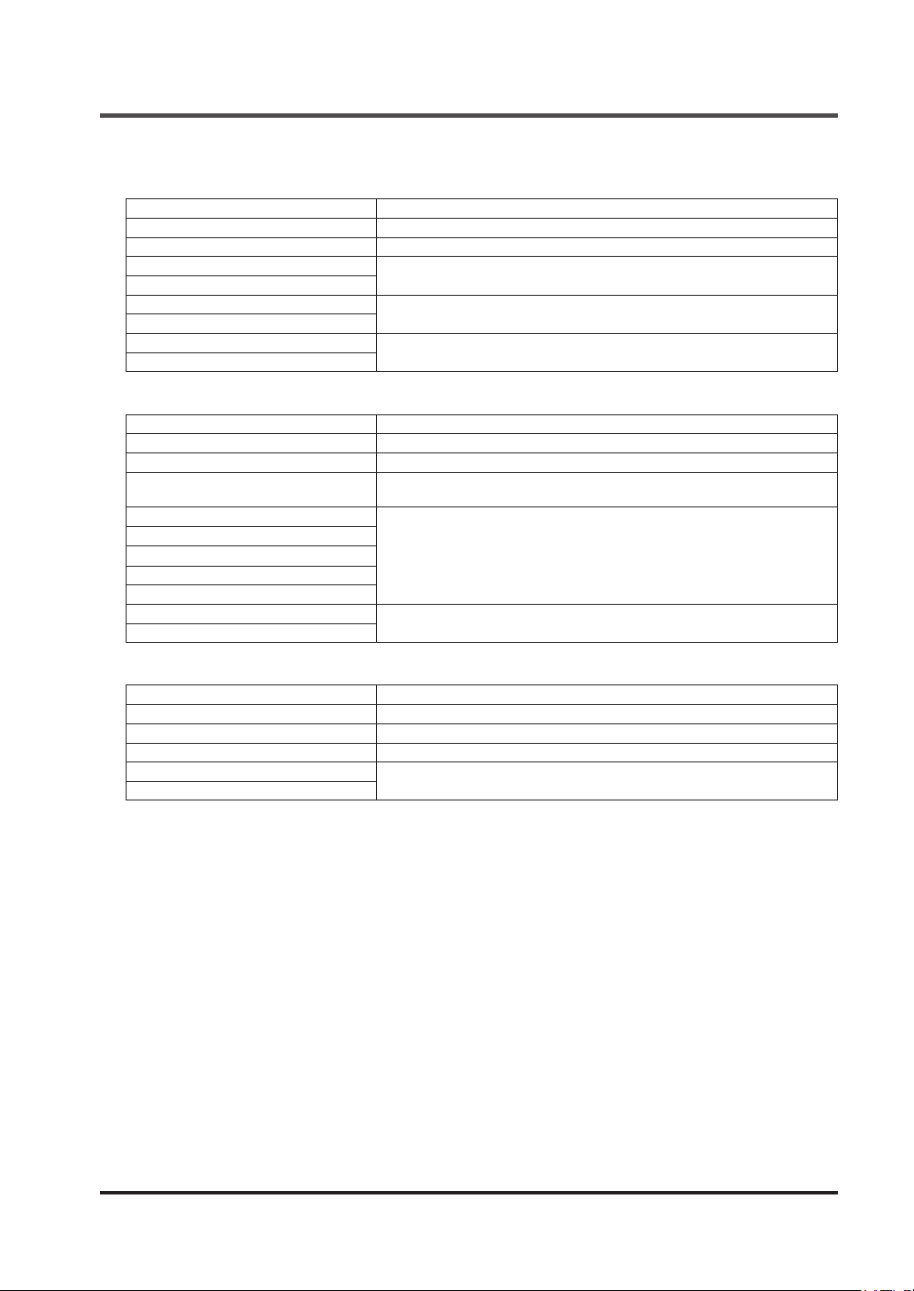
Function code: 0x03
●
<Command>
Data Description
Ofce No.
Function code 0x03
Reading start address (H)
Reading start address (L)
Read number (H)
Read number (L)
CRC-16 (H)
CRC-16 (L)
SF-C21
Word address to read data from
Quantity of data to be read
Message error judgment data
<Response during normal operation>
Data Description
Ofce No.
Function code 0x03
Number of bytes of communication
data
Data 1 to be read (H)
Data 1 to be read (L)
Data n to be read (H)
Data n to be read (L)
…
CRC-16 (H)
CRC-16 (L)
SF-C21
Number of bytes of communication data
Data to be read
Message error judgment data
Functions
equipment address
equipment address
<Response during abnormal operation>
Data Description
Ofce No.
Function code 0x83
Error code Error code
CRC-16 (H)
CRC-16 (L)
SF-C21
Message error judgment data
equipment address
© Panasonic Industrial Devices SUNX Co., Ltd. 2016 37
Page 38

Functions
3-9 USB Communication
CAUTION
Connections to this device via USB are assumed to include temporary connections for e.g., logic
settings and diagnoses.
Constant connections via USB are not allowed.
When this device is connected to PC via a USB cable, various information of this device can be
transmitted and received by using the software tool “
Congurator SF-C
.”
For details, refer to “
Chapter 5 Software Tool
.”
© Panasonic Industrial Devices SUNX Co., Ltd. 201638
Page 39
Functions
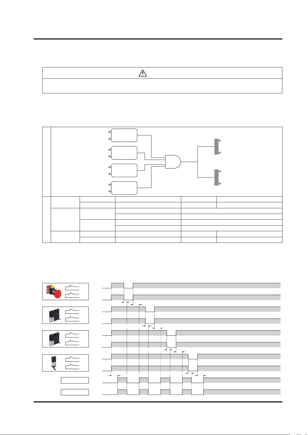
3-10 Logic Selection Function
WARNING
For the safety of the overall system and the conformity to the standards applicable in each region
or country in which this device is installed, take actions on the customer's own responsibility.
This device incorporates eight preset logics and one customizable logic. The preset logics and
customizable logics comply with related international standards.
<No.1. Overall stop control>
Logic diagram
Input
Control
output
Auxiliary
output
Description of settings
IN1
IN2
IN3
IN4
IN5
IN6
IN7
IN8
IN1 / IN2 2NC contact input IN5 / IN6 2NC contact input
IN3 / IN4 2NC contact input IN7 / IN8 2NC contact input
OUT1 / 2
OUT3 / 4
AUX1 Negative logic of OUT 1 / 2 AUX3 Reset trigger
AUX2 Negative logic of OUT 3 / 4 AUX4 Lockout
2NC
2NC
AND
2NC
2NC
Interlock Overall reset
OFF delay 0 sec. (Note 1)
Interlock Overall reset
OFF delay 0 sec. (Note 2)
Notes: 1) Fixed at 0 sec.
2) Time can be selected using this device. For details, refer to “
Function
.”
<Timing chart>
When auto reset is set
●
OUT1/2
OUT3/4
Closed
IN1
Open
T1
IN2
Closed
T2
Open
10ms or less
Closed
IN3
Open
T3
IN4
Closed
T4
Open
Closed
IN5
Open
T5
IN6
Closed
T6
Open
Closed
IN7
Open
T7
IN8
Closed
T8
Open
ON
OFF
ON
OFF
10ms or less
100ms or less
10ms or less
100ms or less
100ms or less
10ms or less
OUT1
OUT2
OUT3
OUT4
3-11 OFF Delay Time Selection
100ms or less100ms or less
© Panasonic Industrial Devices SUNX Co., Ltd. 2016 39
Page 40
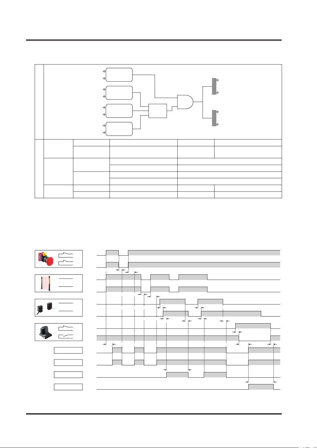
Functions
[No.2: Parallel muting control]
Logic diagram
IN1
IN2
IN3
IN4
IN5
IN6
IN7
IN8
2NC
PNP semicon-
ductor input × 2
(equivalence)
Muting input
(equivalence)
Override input
AND
P-MUTE
IN1 / IN2 2NC contact input IN5 / IN6 Muting input (equivalence)
Input
Control
output
Auxiliary
Description of settings
output
IN3 / IN4
OUT1 / 2
OUT3 / 4
AUX1 Negative logic of OUT 1 / 2 AUX3 Reset trigger
AUX2 Negative logic of OUT 3 / 4 AUX4 Lockout
PNP semiconductor input × 2
(equivalence)
Interlock Overall reset
OFF delay 0 sec. (Note 1)
Interlock Overall reset
OFF delay 0 sec. (Note 2)
IN7 / IN8 Override input
Notes: 1) Fixed at 0 sec.
2) Time can be selected using this device. For details, refer to “
Function
.”
<Timing chart>
When auto reset is set
●
Closed
IN1
Open
T1
IN2
Closed
T2
Open
OUT1/2
OUT3/4
MUTE
OVERRIDE
10ms or less
ON
IN3
OFF
T3
IN4
ON
T4
OFF
ON
IN5
OFF
T5
IN6
ON
T6
OFF
Closed
IN7
Open
T7
IN8
Closed
T8
Open
ON
OFF
ON
OFF
ON
OFF
ON
OFF
10ms or less
Allowable tolerance of 0.03 to 3 sec.
100ms or less
100ms or less
100ms or less
10ms or less 10ms or less
Muting status
OUT1
OUT2
OUT3
OUT4
3-11 OFF Delay Time Selection
Allowable tolerance of 0.03 to 3 sec.
0.05 sec. or less0.05 sec. or less
1 sec. or less
3 sec. + 0.05 sec. or less
10ms or less
Override status
Note: Regarding the muting / override settings, refer to the factory default settings shown in “
tings by Software Tool
.”
© Panasonic Industrial Devices SUNX Co., Ltd. 201640
3-12 Logic Set-
Page 41
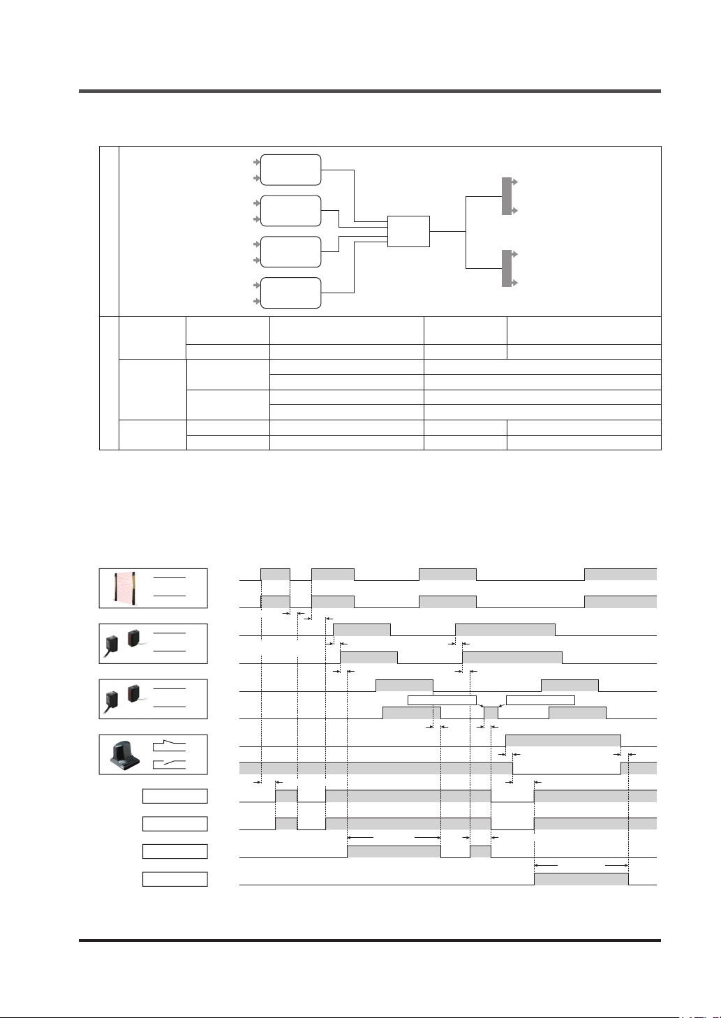
[No.3. Sequential muting control]
PNP semicon-
IN1
ductor input × 2
IN2
(equivalence)
IN3
Muting input
(equivalence)
IN4
IN5
Muting input
(equivalence)
Logic diagram
Input
IN6
IN7
IN8
IN1 / IN2
Override input
PNP semiconductor input × 2
(equivalence)
IN3 / IN4 Muting input (equivalence) IN7 / IN8 Override input
Control
output
Auxiliary
Description of settings
output
OUT1 / 2
OUT3 / 4
AUX1 Negative logic of OUT 1 / 2 AUX3 Reset trigger
AUX2 Negative logic of OUT 3 / 4 AUX4 Lockout
Interlock Overall reset
OFF delay 0 sec. (Note 1)
Interlock Overall reset
OFF delay 0 sec. (Note 2)
Notes: 1) Fixed at 0 sec.
2) Time can be selected using this device. For details, refer to “
Function
.”
S-MUTE
IN5 / IN6 Muting input (equivalence)
Functions
OUT1
OUT2
OUT3
OUT4
3-11 OFF Delay Time Selection
<Timing chart>
When auto reset is set
●
ON
IN1
OFF
T1
IN2
ON
T2
OFF
10ms or less
ON
IN3
OFF
OUT1/2
OUT3/4
MUTE
OVERRIDE
T3
IN4
T4
IN5
T5
IN6
T6
IN7
T7
IN8
T8
ON
OFF
ON
OFF
ON
OFF
Closed
Open
Closed
Open
ON
OFF
ON
OFF
ON
OFF
ON
OFF
Allowable tolerance of
0.03 to 288,000 sec.
100ms or less
Note: Regarding the muting / override settings, refer to the factory default settings shown in “
tings by Software Tool
.”
100ms or less
Allowable tolerance of 0.03 to 288,000 sec.
0.05 sec. or less0.05 sec. or less
Intrusion of obstacles Removal of obstacles
10ms or less
10ms or less
Muting statusMuting status
1 sec. or less
3 sec. + 0.05 sec. or less
Override status
10ms or less
3-12 Logic Set-
© Panasonic Industrial Devices SUNX Co., Ltd. 2016 41
Page 42

Functions
[No.4. Partial stop control 1]
Logic diagram
Input
Control
output
IN1 / IN2 2NC contact input IN5 / IN6 2NC contact input
IN3 / IN4 2NC contact input IN7 / IN8 2NC contact input
OUT1 / 2
OUT3 / 4
Auxiliary
Description of settings
output
IN1
IN2
IN3
IN4
IN5
IN6
IN7
IN8
AUX1 Negative logic of OUT 1 / 2 AUX3 Reset trigger
AUX2 Negative logic of OUT 3 / 4 AUX4 Lockout
2NC
AND
2NC
2NC
AND
2NC
Interlock Partial reset (manual start)
OFF delay 0 sec. (Note 1)
Interlock Partial reset (manual start)
OFF delay 0 sec. (Note 2)
Notes: 1) Fixed at 0 sec.
2) Time can be selected using this device. For details, refer to “
Function
.”
<Timing chart>
Manual reset (standard setting)
●
Closed
IN1
Open
T1
IN2
Closed
T2
IN3
T3
IN4
T4
IN5
T5
IN6
T6
IN7
T7
IN8
T8
INT11/12 (Reset)
INT21/22 (Reset)
OUT1/2
OUT3/4
Open
Closed
Open
Closed
Open
Closed
Open
Closed
Open
Closed
Open
Closed
Open
150ms to 4 sec.
Closed
Open
Closed
Open
100ms or less
ON
OFF
ON
OFF
10ms or less
10ms or less
150ms to 4 sec.
100ms or less
100ms or less
10ms or less
150ms to 4 sec.
100ms or less
OUT1
OUT2
OUT3
OUT4
3-11 OFF Delay Time Selection
10ms or less
150ms to 4 sec.
150ms to 4 sec.
100ms or less
© Panasonic Industrial Devices SUNX Co., Ltd. 201642
Page 43
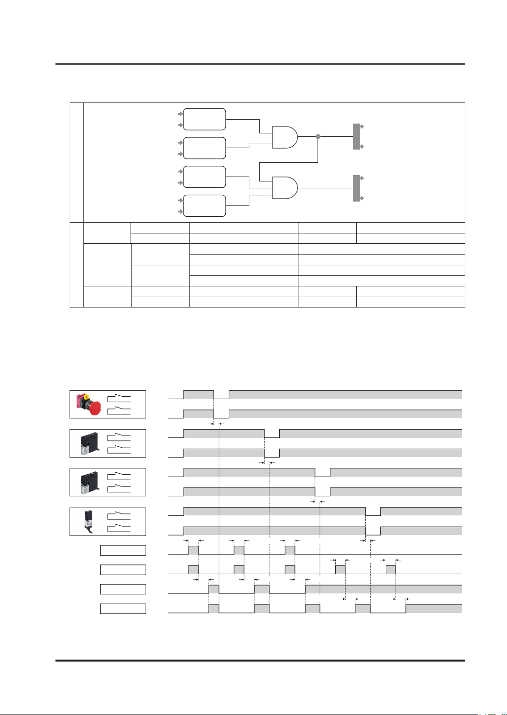
[No.5. Partial stop control 2]
Functions
Logic diagram
Input
Control
output
IN1 / IN2 2NC contact input IN5 / IN6 2NC contact input
IN3 / IN4 2NC contact input IN7 / IN8 2NC contact input
OUT1 / 2
OUT3 / 4
Auxiliary
Description of settings
output
IN1
IN2
IN3
IN4
IN5
IN6
IN7
IN8
AUX1 Negative logic of OUT 1 / 2 AUX3 Reset trigger
AUX2 Negative logic of OUT 3 / 4 AUX4 Lockout
2NC
AND
2NC
2NC
AND
2NC
Interlock Partial reset (manual start)
OFF delay 0 sec. (Note 1)
Interlock Partial reset (manual start)
OFF delay 0 sec. (Note 2)
Notes: 1) Fixed at 0 sec.
2) Time can be selected using this device. For details, refer to “
Function
.”
<Timing chart>
Manual reset (standard setting)
●
Closed
IN1
Open
T1
IN2
Closed
T2
IN3
T3
IN4
T4
IN5
T5
IN6
T6
IN7
T7
IN8
T8
INT11/12 (Reset)
INT21/22 (Reset)
OUT1/2
OUT3/4
Open
Closed
Open
Closed
Open
Closed
Open
Closed
Open
Closed
Open
Closed
Open
150ms to 4 sec.
Closed
Open
Closed
Open
100ms or less
ON
OFF
ON
OFF
10ms or less
10ms or less
150ms to 4 sec.
100ms or less
10ms or less
150ms to 4 sec.
100ms or less
100ms or less
OUT1
OUT2
OUT3
OUT4
3-11 OFF Delay Time Selection
10ms or less
150ms to 4 sec.
150ms to 4 sec.
100ms or less
© Panasonic Industrial Devices SUNX Co., Ltd. 2016 43
Page 44
Functions
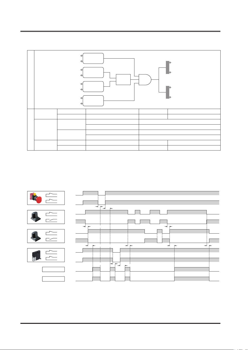
[No.6. Two-hand control]
Logic diagram
Input
Control
output
IN1 / IN2 2NC contact input IN5 / IN6 1NO / 1NC contact input
IN3 / IN4 1NO / 1NC contact input IN7 / IN8 2NC contact input
OUT1 / 2
OUT3 / 4
Auxiliary
Description of settings
output
IN1
IN2
IN3
IN4
IN5
IN6
IN7
IN8
AUX1 Negative logic of OUT 1 / 2 AUX3 Reset trigger
AUX2 Negative logic of OUT 3 / 4 AUX4 Lockout
2NC
1NO/1NC
1NO/1NC
2NC
Twohand
control
AND
Interlock Overall reset
OFF delay 0 sec. (Note 1)
Interlock Overall reset
OFF delay 0 sec. (Note 2)
Notes: 1) Fixed at 0 sec.
2) Time can be selected using this device. For details, refer to “
Function
.”
<Timing chart>
When auto reset is set
●
Closed
IN1
Open
T1
IN2
Closed
T2
Open
OUT1/2
OUT3/4
10ms or less
Closed
IN3
Open
T3
IN4
Closed
T4
Open
Closed
IN5
Open
T5
IN6
Closed
T6
Open
Closed
IN7
Open
T7
IN8
Closed
T8
Open
ON
OFF
ON
OFF
Within 0.5 sec. Within 0.5 sec.
Within 100ms
10ms or less
Within 100ms
10ms or less
Within 100ms
OUT1
OUT2
OUT3
OUT4
3-11 OFF Delay Time Selection
Within 100ms
10ms or less
© Panasonic Industrial Devices SUNX Co., Ltd. 201644
Page 45
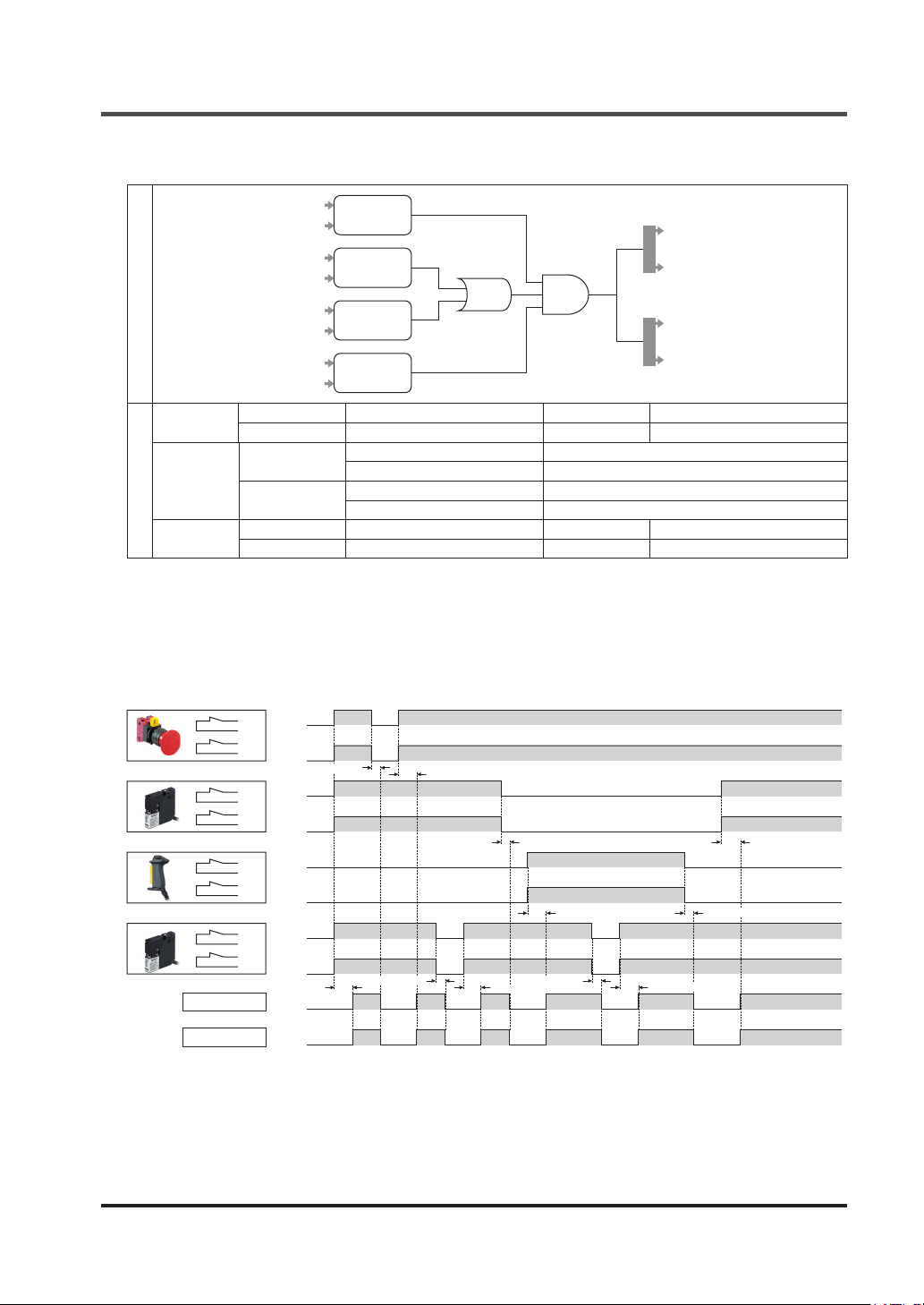
[No.7. OR control]
Functions
Logic diagram
Input
Control
output
IN1 / IN2 2NC contact input IN5 / IN6 2NC contact input
IN3 / IN4 2NC contact input IN7 / IN8 2NC contact input
OUT1 / 2
OUT3 / 4
Auxiliary
Description of settings
output
IN1
IN2
IN3
IN4
IN5
IN6
IN7
IN8
AUX1 Negative logic of OUT 1 / 2 AUX3 Reset trigger
AUX2 Negative logic of OUT 3 / 4 AUX4 Lockout
2NC
2NC
ANDOR
2NC
2NC
Interlock Overall reset
OFF delay 0 sec. (Note 1)
Interlock Overall reset
OFF delay 0 sec. (Note 2)
Notes: 1) Fixed at 0 sec.
2) Time can be selected using this device. For details, refer to “
Function
.”
<Timing chart>
When auto reset is set
●
Closed
IN1
Open
T1
IN2
Closed
T2
Open
OUT1/2
OUT3/4
IN3
T3
IN4
T4
IN5
T5
IN6
T6
IN7
T7
IN8
T8
Closed
Open
Closed
Open
Closed
Open
Closed
Open
Closed
Open
Closed
Open
100ms or less
ON
OFF
ON
OFF
10ms or less
10ms or less
100ms or less
10ms or less
10ms or less
100ms or less
100ms or less
OUT1
OUT2
OUT3
OUT4
3-11 OFF Delay Time Selection
100ms or less
10ms or less
100ms or less
© Panasonic Industrial Devices SUNX Co., Ltd. 2016 45
Page 46
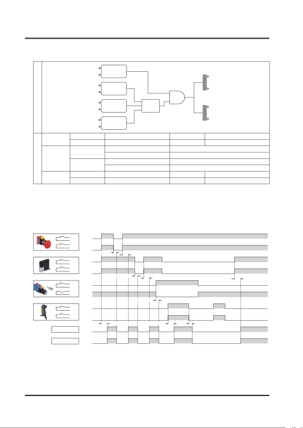
Functions
[No.8. Operation mode selection control]
Logic diagram
Input
Control
output
IN1 / IN2 2NC contact input IN5 / IN6 Key selector input
IN3 / IN4 2NC contact input IN7 / IN8 2NC contact input
OUT1 / 2
OUT3 / 4
Auxiliary
Description of settings
output
IN1
IN2
IN3
IN4
IN5
IN6
IN7
IN8
AUX1 Negative logic of OUT 1 / 2 AUX3 Reset trigger
AUX2 Negative logic of OUT 3 / 4 AUX4 Lockout
2NC
2NC
Key selector
input
2NC
AND
Input
select
Interlock Overall reset
OFF delay 0 sec. (Note 1)
Interlock Overall reset
OFF delay 0 sec. (Note 2)
Notes: 1) Fixed at 0 sec.
2) Time can be selected using this device. For details, refer to “
Function
.”
<Timing chart>
When auto reset is set
●
Closed
IN1
Open
T1
IN2
Closed
T2
Open
OUT1/2
OUT3/4
10ms or less
Closed
IN3
Open
T3
IN4
Closed
T4
Open
Closed
IN5
Open
T5
IN6
Closed
T6
Open
Closed
IN7
Open
T7
IN8
Closed
T8
Open
ON
OFF
ON
OFF
10ms or less
100ms or less 100ms or less
100ms or less
100ms or less
10ms or less
OUT1
OUT2
OUT3
OUT4
3-11 OFF Delay Time Selection
100ms or less
10ms or less
© Panasonic Industrial Devices SUNX Co., Ltd. 201646
Page 47
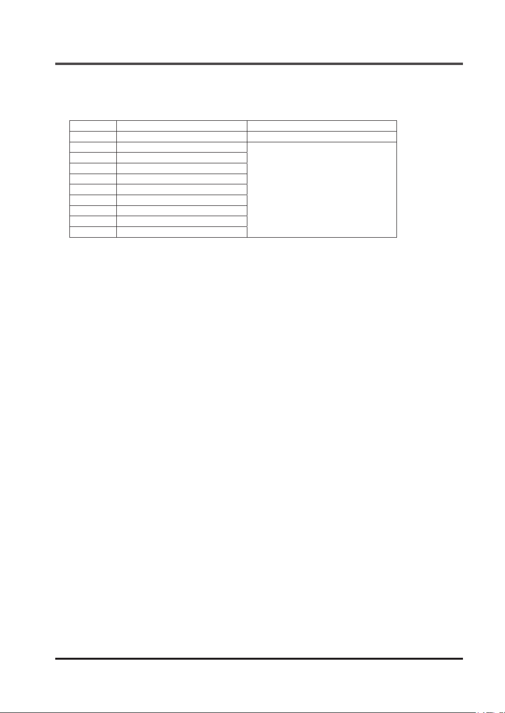
3-11 OFF Delay Time Selection Function
The OFF delay times that this device can set are as follows:
No. OFF delay time Stop category
0 0 sec. 0
1 0.1 sec.
2 0.5 sec.
3 1 sec.
4 2 sec.
5 5 sec.
6 10 sec.
7 15 sec.
8 30 sec.
9 60 sec.
Note: Only OUT3 / 4 can be set with this device.
Functions
1
© Panasonic Industrial Devices SUNX Co., Ltd. 2016 47
Page 48
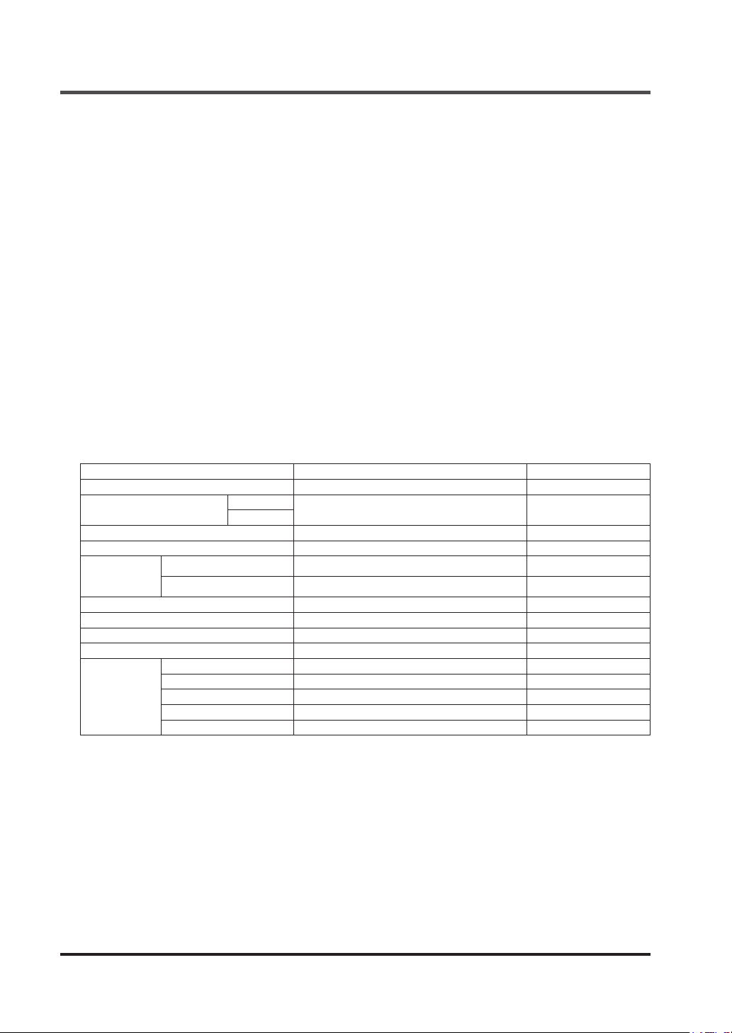
Functions
3-12 Logic Settings by Software Tool
The software tool is available to change the settings of the following items. When logics are set,
control output 1 / 2 maintains OFF status. For details, refer to “
<Setting item>
● Input mode
● Logic setting
● Output mode (OFF delay, reset)
● Auxiliary output mode
<Detailed setting item>
● Input mismatch allowable time
● Input lter time
● ON delay time
● Allowable time difference in muting input
● Muting duration
● Exit-only muting time
● Muting input condition
● Override duration
● MODBUS (RS-485) communication conditions (Baud rate, parity bit presence, parity bit type,
stop bit, and communication address)
Chapter 5 Software Tool
.”
Item Setting range
Input mismatch allowable time 0 (unlimited) to 60 sec. (in units of 0.01 sec.) 1 sec.
Input lter time
ON delay time 0 to 5,940 sec. (in units of 0.1 sec.) 0 sec.
OFF delay time 0 to 60 sec. (in units of 0.1 sec.) 0 sec.
Allowable time
difference in
muting input
Muting duration 0 (unlimited) to 5,940 sec. (in units of 1 sec.) 5,940 sec.
Exit-only muting time (Note 2) 1 to 4 sec. (in units of 0.1 sec.) 0 sec.
Muting input condition No priority/A priority/B (D) Priority No priority
Override duration 1 to 600 sec. (in units of 1 sec.) 60 sec.
RS-485
communication
condition
Notes: 1) Preset logic is xed.
2) This setting in only for parallel muting.
Parallel muting 1 to 10 sec. (in units of 1 sec.) 3 sec.
Sequential muting
Baud rate 9,600 bps to 115,200 bps 9,600 bps
Parity bit presence Without / With With
Parity bit type Odd / even Odd
Stop bit 1 bit / 2 bits 1 bit
Communication address 1 to 247 1
ON - OFF
OFF - ON
0 to 1 sec. (in units of 0.01 sec.) 0 sec.
0 (unlimited) to 288,000 sec. (in units of 1 sec.)
Factory default (Note 1)
288,000 sec.
Factory settings of customizable logics are invalid.
© Panasonic Industrial Devices SUNX Co., Ltd. 201648
Page 49

3-13 Logic Manual Stop / Start Function
The logics of this device can be stopped and started manually.
The logics of this device are stopped according to the procedure below.
Step 1 Switch the mode selector switch to the “PROG” side.
Step 2 Press the rotary switch.
The logics of this device are started according to the procedure below.
Step 1 Switch the mode selector switch to the “RUN” side.
Step 2 Press the rotary switch.
Functions
© Panasonic Industrial Devices SUNX Co., Ltd. 2016 49
Page 50
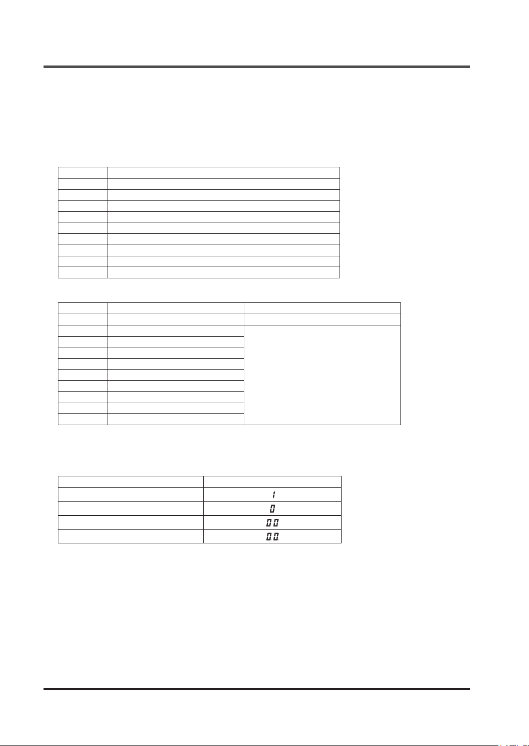
Chapter 4 Setting of Logics
4-1 Types and Settings of Logics
For this device, logic Nos. 0 to 9 and nine types of OFF delay time can be specied.
With logic No. 0 specied, the logic is customizable. This device must be connected to a PC to
make settings with a software tool.
Logics corresponding to Nos. are shown in the table below.
No. Logic
0 Customizable logic
1 Overall stop control
2 Parallel muting control
3 Sequential muting control
4 Partial stop control 1
5 Partial stop control 2
6 Two-hand control
7 OR control
8 Operation mode selection control
OFF delay times and stop categories corresponding to Nos. are shown in the table below.
No. OFF delay time Stop category
0 0 sec. 0
1 0.1 sec.
2 0.5 sec.
3 1 sec.
4 2 sec.
5 5 sec.
6 10 sec.
7 15 sec.
8 30 sec.
9 60 sec.
1
4-1-1 Factory Setting
Factory setting of this device is as shown in the table below.
Item Factory setting
Logic
OFF delay time No.
Password 1
Password 2
© Panasonic Industrial Devices SUNX Co., Ltd. 201650
Page 51
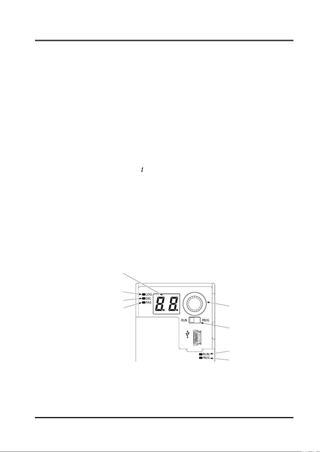
Preparation for Logic Setting
4-2 Preparation for Logic Setting
Preset logic can be set by using this device and power supply only. At the time of setting, devices do not have to be connected to the input section or output section.
Connect power supplies (24V DC and 0V) to the terminal block for internal power supply and
the terminal block for external power supply in this device.
If power is supplied to either one of them, this device will not operate.
4-2-1 Turning ON the Power
Conrm that the mode selector switch is turned to the “RUN” side (left side: factory setting) and
then turn ON the power. The diagnosis function of this device carries out initial diagnosis, turning ON and OFF the indicators one by one.
After the end of initial diagnosis, the operation indicator (green) lights up.
If a terminal block is connected only to the power supply, auxiliary output indicator 1 / 2 / 4 (orange) and interlock indicator 1 / 2 (yellow) light up.
The other indicators turn OFF.
Pressing the rotary switch displays “ ” (factory setting) in the 7-segment indicator (red), turning
ON the logic selection indicator (orange).
4-2-2 Portions Used in Settings
The following indicators and switches are used for preset logic settings.
● 7-segment indicator (Red)
● Logic selection indicator (Orange)
● Delay selection indicator (Orange)
● Password selection indicator (Orange)
● Operation indicator (Green)
● Setting indicator (Orange)
● Rotary switch
● Mode selector switch
7-segment indicator (Red)
Logic selection indicator (Orange)
Delay selection indicator (Orange)
Password selection indicator (Orange)
© Panasonic Industrial Devices SUNX Co., Ltd. 2016 51
Rotary switch
Mode selector switch
Operation indicator (Green)
Setting indicator (Orange)
Page 52
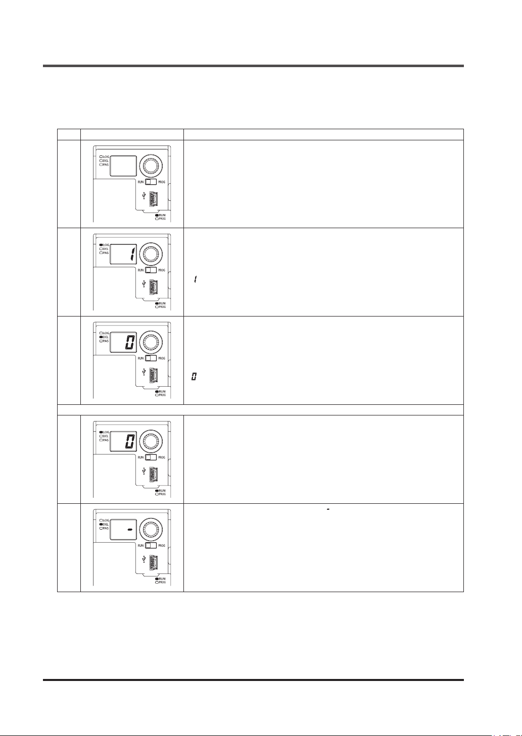
Operation in RUN Mode and the Display
4-3 Operation in RUN Mode and the Display
4-3-1 Operation and Display During Normal Operation
Step
Status of indicators and switches
1
2
3
Mode selector switch: RUN side
Operation indicator (green): Lights up
The power saving function of this device turns OFF the 7-segment indicator
(red) 3 sec. after power ON, the end of initial diagnosis, or nal operation.
Press the rotary switch.
The logic No. currently set is displayed in the 7-segment indicator (red).
Logic selection indicator (orange) lights up.
“ : Overall stop control” is set at factory.
Rotate the rotary switch.
The currently set No. for OFF delay time is displayed in the 7-segment indicator (red).
Delay selection indicator (orange) lights up.
“ : 0 sec.” is set at factory.
Description
Rotating the rotary switch returns to No.1.
Logic No. 0 is customizable logic.
To use customizable logic, this device must be connected to a PC to make
settings by a software tool.
4
5
Refer to “
Selecting logic No. 0 always displays “ ” in the 7-segment indicator (red) as
the OFF delay time.
Chapter 5 Software Tool
”.
© Panasonic Industrial Devices SUNX Co., Ltd. 201652
Page 53
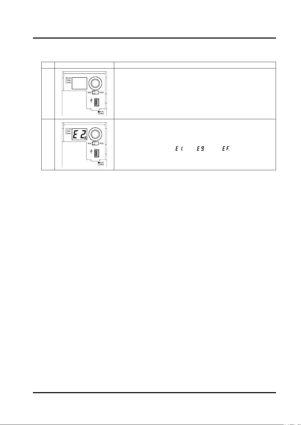
Operation in RUN Mode and the Display
4-3-2 Display When an Error Occurs
Step
Status of indicators and switches
Mode selector switch: RUN side
Operation indicator (green): Lights up
During normal operation
1
2
The power saving function of this device turns OFF the 7-segment indicator
(red) 3 sec. after power ON, the end of initial diagnosis, or nal operation.
Occurrence of abnormality (Example: internal failure, two inputs short-circuit-
ed, etc.)
If an error occurs, an error code is displayed in the 7-segment indicator (red),
and dots blink.
Either one of error codes “ ” to “ ” and “ ” is displayed in the
7-segment indicator (red).
For the error codes, refer to “
Description
Chapter 7 Troubleshooting
”.
© Panasonic Industrial Devices SUNX Co., Ltd. 2016 53
Page 54
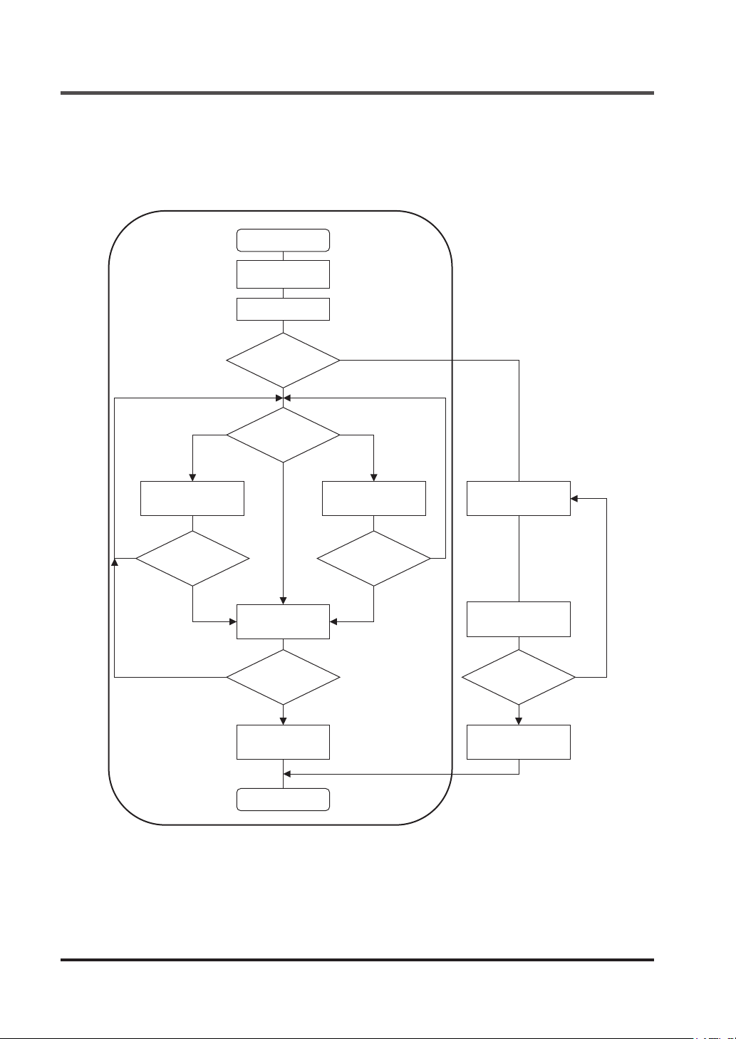
Setting of Logics and OFF Delay Time
4-4 Setting of Logics and OFF Delay Time
4-4-1 Flowchart of Logic and OFF Delay Time
Logic and OFF delay time are set according to the ow in the gure below.
PROG mode
Indicator ON
conrmation
Password entry
Select set mode
Select
operation
setting
YES
Set logic
Return to Select
operation setting
NO NO
Conrm
operation setting
YES YES
Return to Select
operation setting
NO NO
Write / conrm
operation setting
End of setting
Set OFF delay
time
Return to Select
operation setting
Set password
YES
Conrm Password
Return to Set
password
Write / conrm
password
© Panasonic Industrial Devices SUNX Co., Ltd. 201654
Page 55
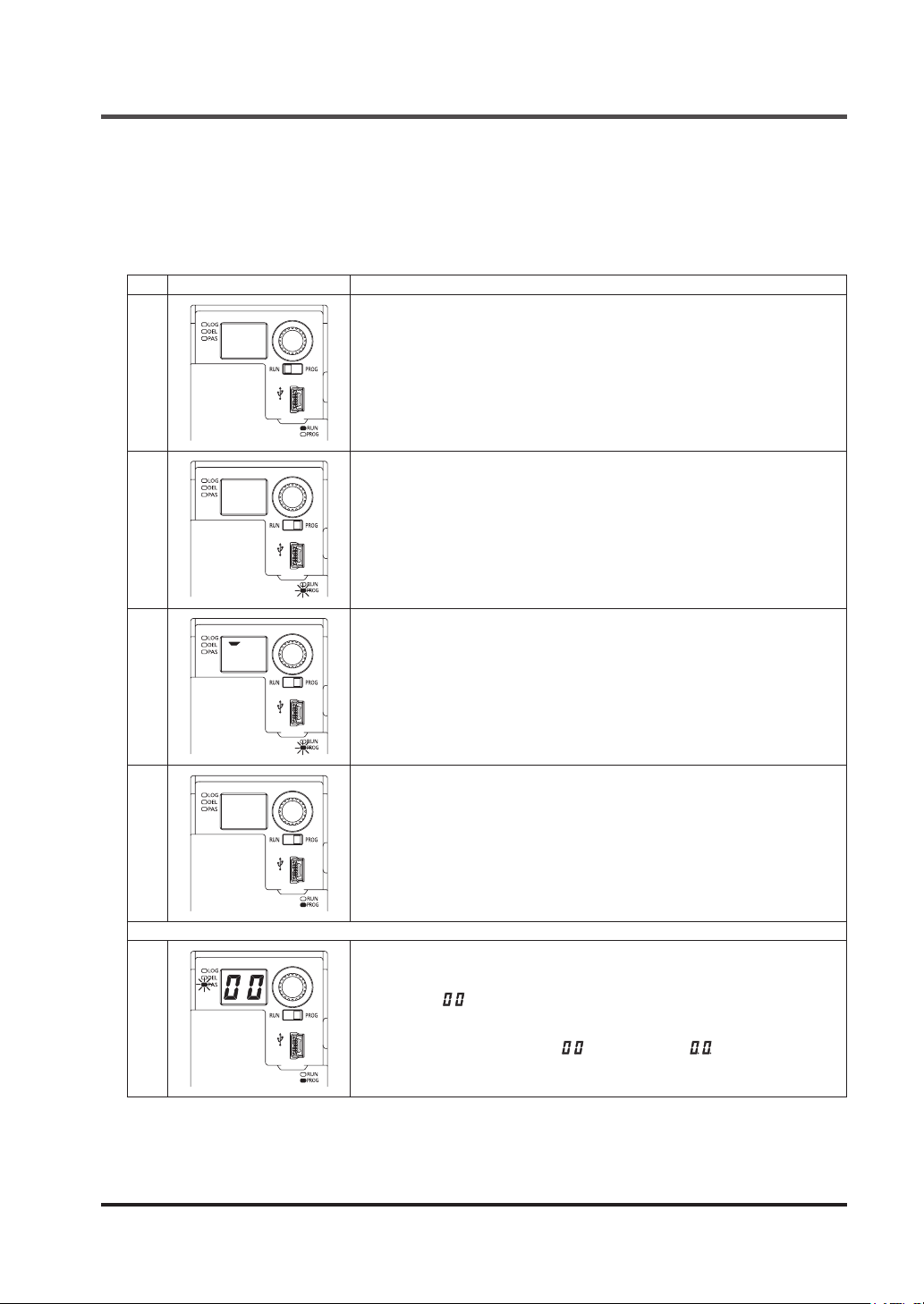
Setting of Logics and OFF Delay Time
4-4-2 Operation Procedure for Setting Logic and OFF Delay Time
Procedure for setting logic and OFF delay time in this device is described below.
To stop setting logic and OFF delay time before Step 23 in the table below, turn the mode selector switch to the “RUN” side, and the settings will be canceled. After Step 24 or later, the settings cannot be canceled.
Step
Status of indicators and switches
1
2
Mode selector switch: RUN side
Operation indicator (green): Lights up
The power saving function of this device turns OFF the 7-segment indicator
(red) 3 sec. after power ON, the end of initial diagnosis, or nal operation.
Switch the mode selector switch to the “PROG” side.
This device transitions to “PROG mode.”
The operator indicator (green) turns OFF.
The setting indicator (orange) blinks.
This device automatically transitions to “Indicator ON conrmation.”
Description
Individual segments of the 7-segment indicator (red) light up one by one.
3
4
5
Check for an error code displayed in the 7-segment indicator (red).
Press the rotary switch.
The setting indicator (orange) status changes from blinking to lighting up.
Press the rotary switch.
Transition to “Enter password.”
Password selection indicator (orange) blinks.
Password 1 “ ” is displayed in the the 7-segment indicator (red).
Enter password 1 and password 2.
At factory, password 1 is set to “ ”, password 2, “ ”.
© Panasonic Industrial Devices SUNX Co., Ltd. 2016 55
Page 56
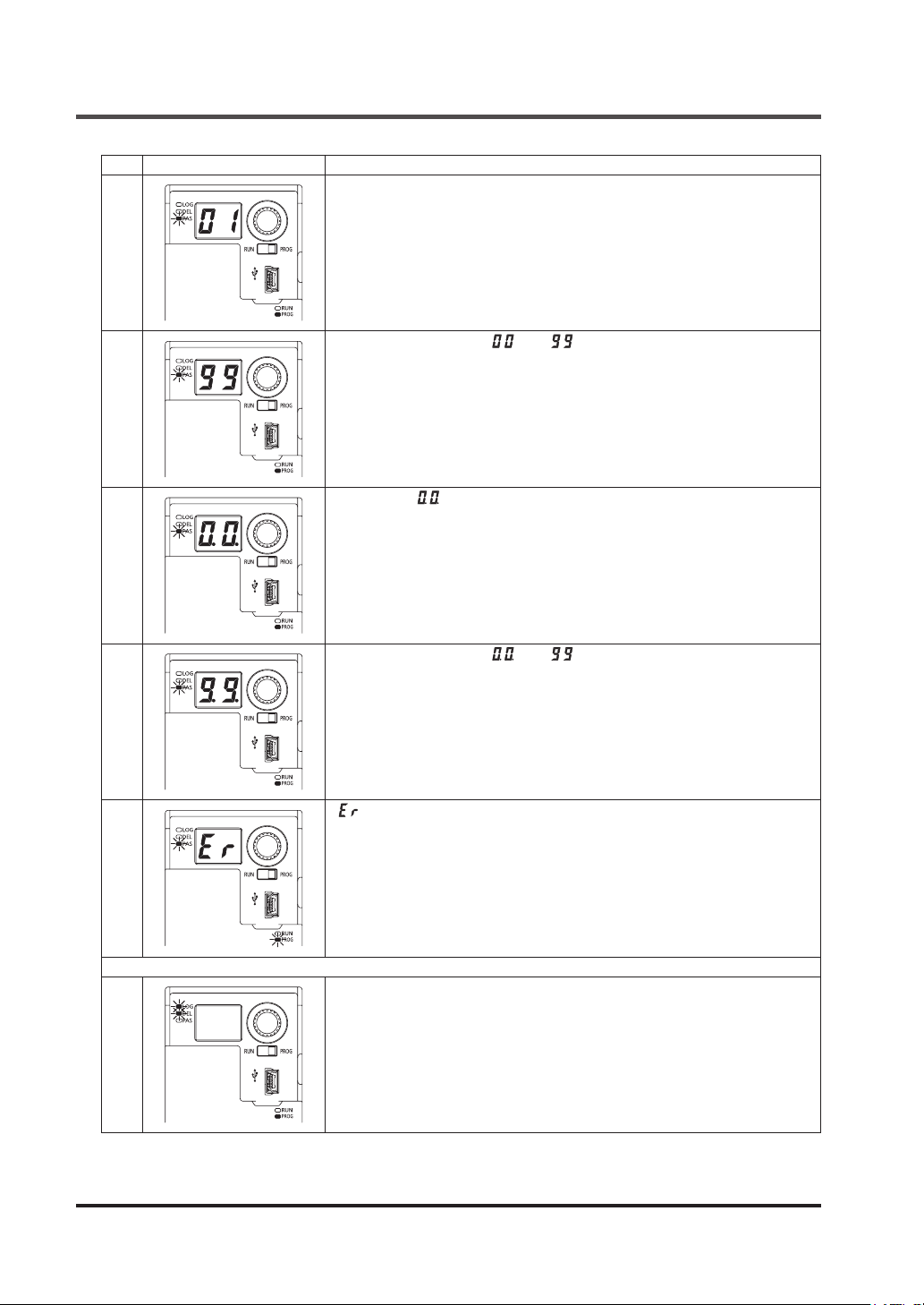
Setting of Logics and OFF Delay Time
Step
Status of indicators and switches
Select password.
Select a number by rotating the rotary switch.
6
Select password 1 from “ ” to “ ”.
Determine password 1 by pressing the rotary switch.
7
Password 2 “ ” is displayed in the the 7-segment indicator (red).
Select password 2.
Similarly, select a number by rotating the rotary switch.
8
Description
10
11
Select password 2 from “ ” to “ ”.
Determine the password 2 by pressing the rotary switch.
• When password 1 and password 2 are correct, proceed to Step 11.
9
• When password 1 or 2 is incorrect, proceed to Step 10.
“ ” is displayed in the 7-segment indicator (red).
Pressing the rotary switch returns to Step 5.
Enter the password again.
Transition to “Select setting mode.”
Password selection indicator (orange) turns OFF.
The logic selection indicator (orange) and delay selection indicator (orange)
blink.
Pressing the rotary switch proceeds to Step 13.
© Panasonic Industrial Devices SUNX Co., Ltd. 201656
Page 57
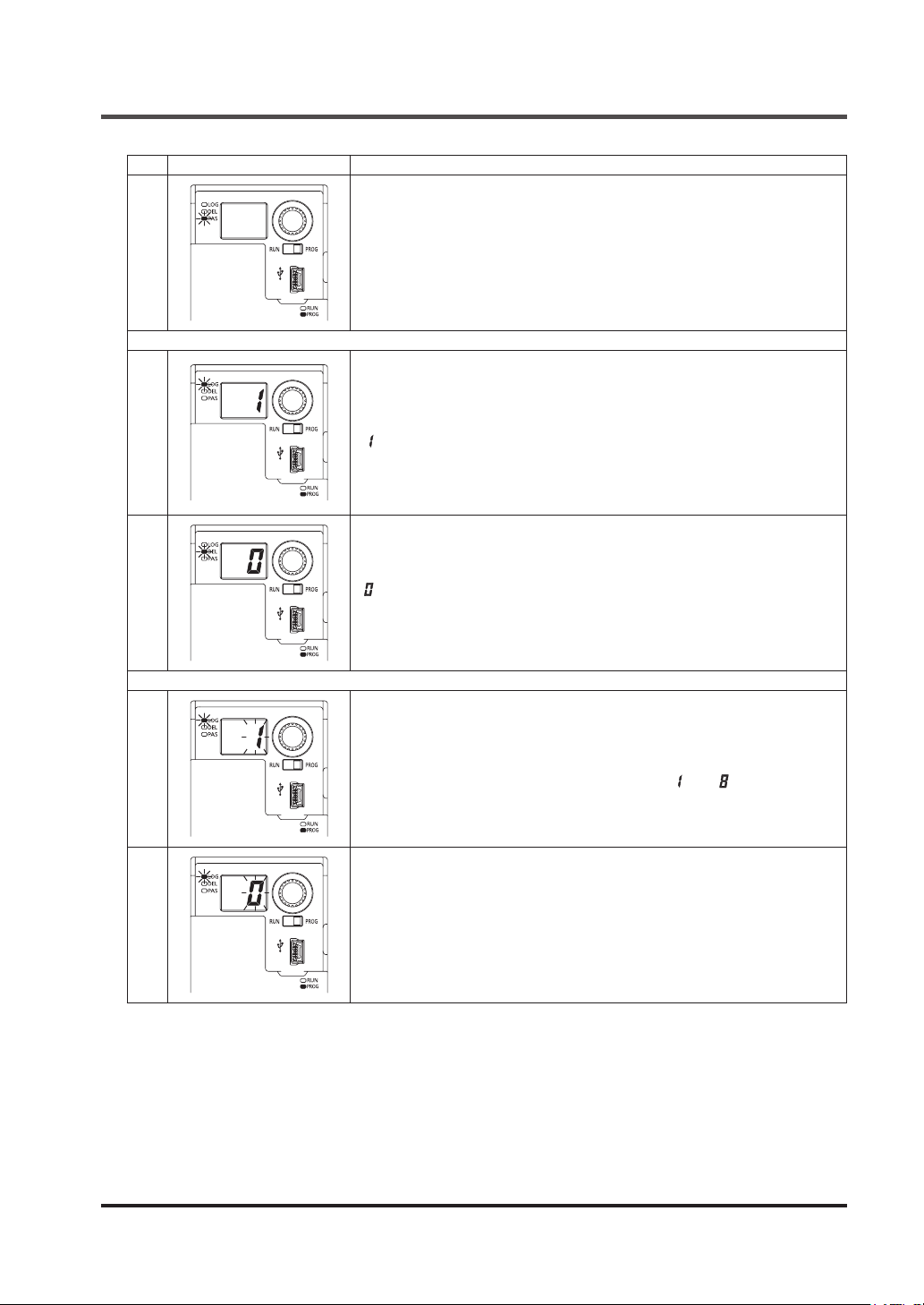
Step
Status of indicators and switches
12
13
Setting of Logics and OFF Delay Time
Description
Rotating the rotary switch blinks the password selection indicator (orange).
Rotate the rotary switch further to return to Step 11.
Transition to “Select operation setting.”
The logic No. currently set is displayed in the 7-segment indicator (red).
Logic selection indicator (orange) blinks.
“ : Overall stop control” is set at factory.
Rotating the rotary switch proceeds to Step 14.
Pressing the rotary switch proceeds to Step 15.
Holding down the rotary switch proceeds to Step 21.
The currently set No. for OFF delay time is displayed in the 7-segment indicator (red).
Delay selection indicator (orange) blinks.
14
15
16
“ : 0 sec.” is set at factory.
Rotating the rotary switch returns to Step 13.
Pressing the rotary switch proceeds to Step 18.
Holding down the rotary switch proceeds to Step 21.
Transition to “Set logic.”
The logic No. currently set is displayed in the 7-segment indicator (red) and
blinks.
Rotate the rotary switch to select Logic No. from “ ” to “ ”.
Logic No. 0 is customizable logic.
To use customizable logic, this device must be connected to a PC to make
settings by a software tool.
Refer to “
If Logic No. 0 is selected, “Set OFF delay time” cannot be selected. OFF delay time for Logic No. 0 is changed with a software tool.
Chapter 5 Software Tool
.”
© Panasonic Industrial Devices SUNX Co., Ltd. 2016 57
Page 58
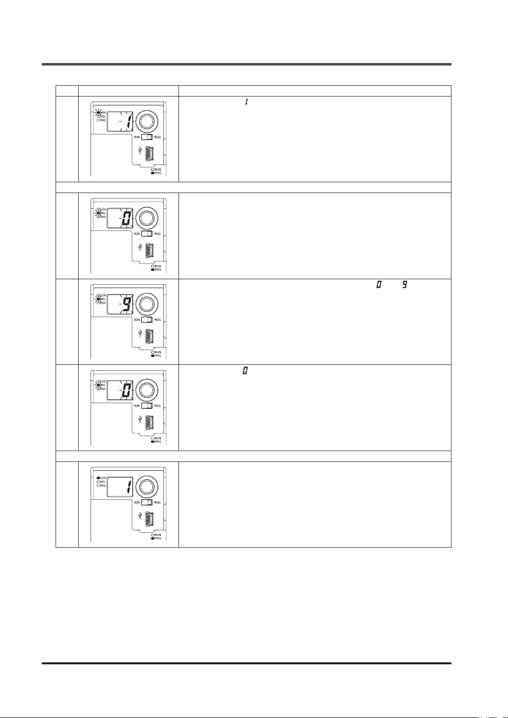
Setting of Logics and OFF Delay Time
Step
Status of indicators and switches
As an example, “ ” is selected.
Press the rotary switch for the determination and return to Step 13.
Holding down the rotary switch determines the selection and then returns to
17
18
19
Step 21.
Transition to “Set OFF delay time.”
The current No. for OFF delay time is displayed in the 7-segment indicator
(red) and blinks.
Rotate the rotary switch to select OFF delay time from “ ” to “ ”.
Description
20
21
As an example, “ ” is selected.
Press the rotary switch for the determination and return to Step 14.
Holding down the rotary switch determines the selection and then returns to
Step 21.
Transition to “Conrm operation setting.”
Logic No. is displayed in the the 7-segment indicator (red).
Rotate the rotary switch.
© Panasonic Industrial Devices SUNX Co., Ltd. 201658
Page 59
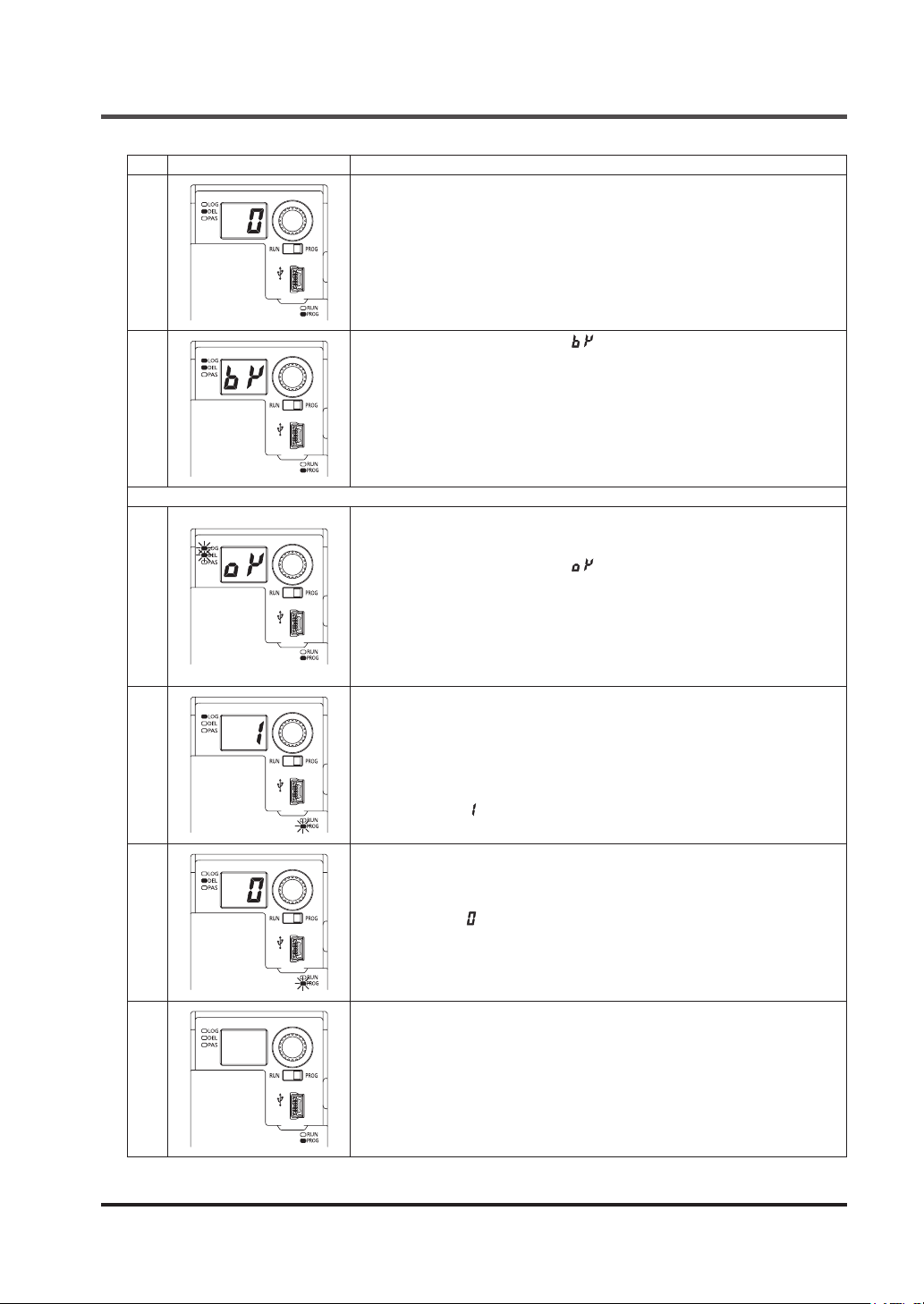
Step
Status of indicators and switches
22
Setting of Logics and OFF Delay Time
Description
The No. for OFF delay time is displayed in the 7-segment indicator (red).
• When the selected logic and OFF delay time are conrmed, hold down the
rotary switch to proceed to Step 24.
• If either or both of the logic or OFF delay time differ from those selected,
rotate the rotary switch.
In the 7-segment indicator (red), “ ” indicating “Back” is displayed.
The logic selection indicator (orange) and delay selection indicator (orange)
light up.
23
24
25
26
Pressing the rotary switch returns to Step 13.
Select logic and OFF delay time again.
Holding down the rotary switch changes the display to that shown in the illustration at left.
In the 7-segment indicator (red), “ ” indicating “OK” is displayed.
The logic selection indicator (orange) and delay selection indicator (orange)
blink.
Transition to “Write / conrm operation setting.”
The logic and OFF delay time set in this device have been changed.
Releasing the hand from the rotary switch proceeds to the next step.
After the end of write operation, logic No. and No. for OFF delay time are
alternately displayed in the 7-segment indicator (red).
A logic No. is shown in the illustration at left.
Logic selection indicator (orange) lights up.
As an example, “ ” is selected.
No. for OFF delay time is shown in the illustration at left.
Delay selection indicator (orange) lights up.
As an example, “ ” is selected.
After conrming operation setting, press the rotary switch.
Transition to “Quit setting mode.”
27
© Panasonic Industrial Devices SUNX Co., Ltd. 2016 59
Page 60
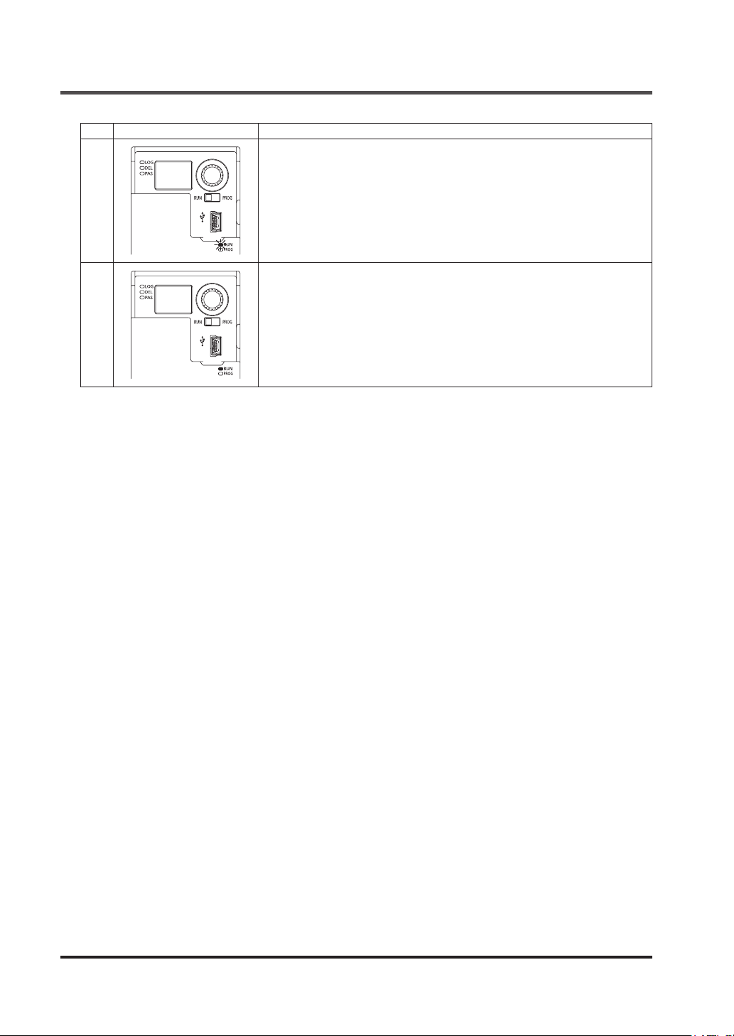
Setting of Logics and OFF Delay Time
Step
Status of indicators and switches
Switch the mode selector switch to the “RUN” side.
The operation indicator (green) blinks.
Description
28
29
Press the rotary switch.
The operation indicator (green) status changes to lighting up.
This device transitions to “RUN” status.
© Panasonic Industrial Devices SUNX Co., Ltd. 201660
Page 61
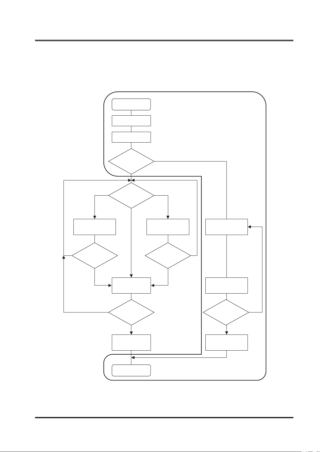
4-5 Change Password
4-5-1 Flowchart of Change Password
Password is changed according to the owchart below.
Set mode
Indicator ON
conrmation
Password entry
Select set mode
Select
operation
setting
Change Password
Set logic
YES YES
Return to Select
operation setting
NO NO
Conrm Set
operation setting
YES YES
Return to Select
operation setting
NO NO
Write / conrm
operation setting
End of setting
Set OFF delay
time
Return to Select
operation setting
Set password
Conrm password
Return to Set
password
Write / conrm
password
© Panasonic Industrial Devices SUNX Co., Ltd. 2016 61
Page 62
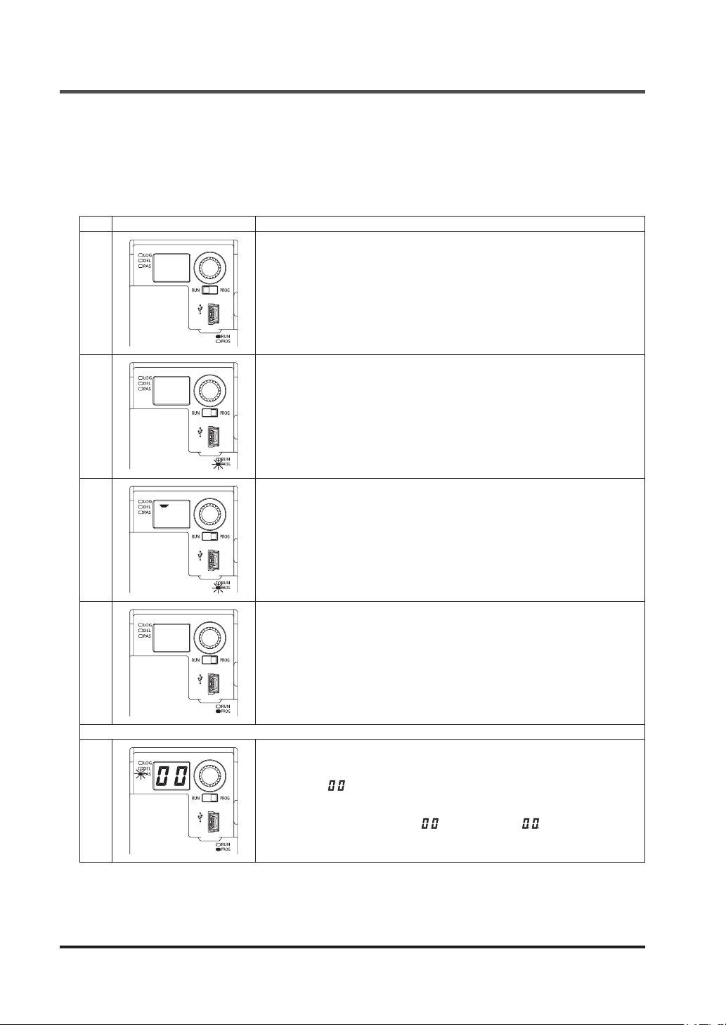
Change Password
4-5-2 Operation Procedure for Change Password
The procedure for changing the password (password 1 / 2) set in this device is described below.
To stop changing the password before Step 19 in the table below, turn the mode selector switch
to the “RUN” side, and the operation for change password will be canceled. After Step 20 or later, the operation cannot be canceled.
Step
Status of indicators and switches
1
2
Mode selector switch: RUN side
Operation indicator (green): Lights up
The power saving function of this device turns OFF the 7-segment indicator
(red) 3 sec. after power ON, the end of initial diagnosis, or nal operation.
Switch the mode selector switch to the “PROG” side.
This device transitions to “PROG mode.”
The operation indicator (green) turns OFF.
The setting indicator (orange) blinks.
This device automatically transitions to “Indicator ON conrmation.”
Description
Individual segments of the 7-segment indicator (red) light up one by one.
3
4
5
Check for an error code displayed in the 7-segment indicator (red).
Press the rotary switch.
The setting indicator (orange) status changes from blinking to lighting up.
This device transitions to “PROG mode.”
Press the rotary switch.
Transition to “Enter password.”
Password selection indicator (orange) blinks.
Password 1 “ ” is displayed in the the 7-segment indicator (red).
Select password 1 and password 2.
At factory, password 1 is set to “ ”, password 2, “ ”.
© Panasonic Industrial Devices SUNX Co., Ltd. 201662
Page 63
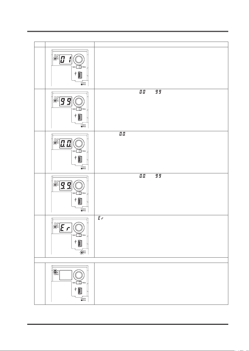
Step
Status of indicators and switches
6
7
8
Change Password
Description
Select password 1.
Select a number by rotating the rotary switch.
Select password 1 from “ ” to “ ”.
Determine password 1 by pressing the rotary switch.
Password 2 “ ” is displayed in the the 7-segment indicator (red).
Select password 2.
Similarly, select a number by rotating the rotary switch.
10
11
Select password 2 from “ ” to “ ”.
Determine password 2 by pressing the rotary switch.
When password 1 and password 2 are correct, proceed to Step 11.
9
When password 1 or 2 is incorrect, proceed to Step 10.
“ ” is displayed in the 7-segment indicator (red).
Pressing the rotary switch returns to Step 5.
Enter the password again.
Transition to “Select setting mode.”
Password selection indicator (orange) turns OFF.
The logic selection indicator (orange) and delay selection indicator (orange)
blink.
© Panasonic Industrial Devices SUNX Co., Ltd. 2016 63
Page 64
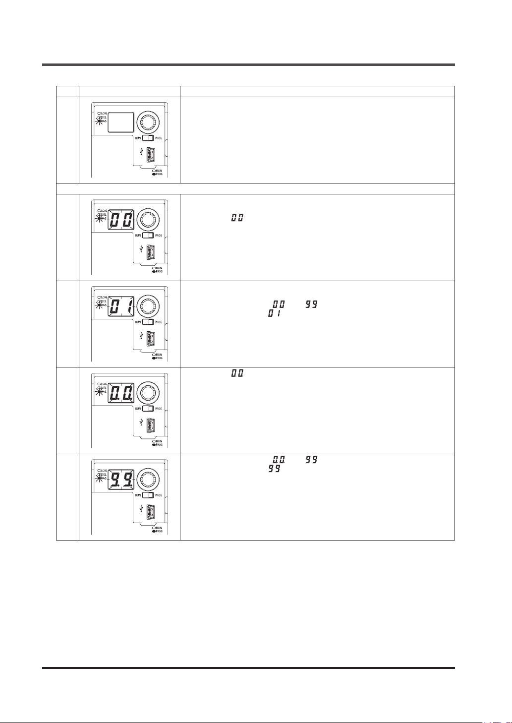
Change Password
Step
Status of indicators and switches
12
13
14
Description
Rotating the rotary switch blinks the password selection indicator (orange).
Press the rotary switch.
Transition to “Set password.”
Password 1 “ ” is displayed in the the 7-segment indicator (red).
Set password 1.
Select a number by rotating the rotary switch.
Select password 1 from “ ” to “ ”.
As an example, select “ ” for password 1 and then determine it by pressing the rotary switch.
15
16
Password 2 “ ” is displayed in the the 7-segment indicator (red).
Set password 2.
Similarly, select a number by rotating the rotary switch.
Select password 2 from “ ” to “ ”.
As an example, select “ ” for password 2 and then determine it by pressing the rotary switch.
© Panasonic Industrial Devices SUNX Co., Ltd. 201664
Page 65
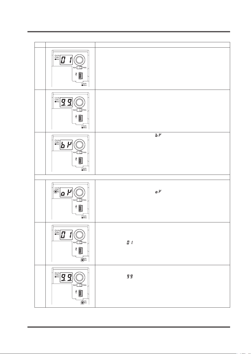
Step
Status of indicators and switches
17
18
19
Change Password
Description
Transition to “Conrm password.”
Display password 1.
Rotate the rotary switch.
Display password 2.
When the selected password is correct, hold down the rotary switch to proceed to Step 20.
If the selected password is incorrect, rotate the rotary switch.
In the 7-segment indicator (red), “ ” indicating “Back” is displayed.
Pressing the rotary switch returns to Step 13.
Set passwords 1 and 2 again.
20
21
22
Holding down the rotary switch changes the display to that shown in the illustration at left.
In the 7-segment indicator (red), “ ” indicating “OK” is displayed.
Password selection indicator (orange) blinks.
Transition to “Write / conrm password.”
The passwords of this device have been changed.
Releasing the hand from the rotary switch proceeds to the next step.
After the end of write operation, password 1 and password 2 are alternately
displayed in the 7-segment indicator (red).
Password 1 is shown in the illustration at left.
As an example, “ ” is shown.
Password 2 is shown in the illustration at left.
As an example, “ ” is shown.
After conrming password 1 and password 2, press the rotary switch.
© Panasonic Industrial Devices SUNX Co., Ltd. 2016 65
Page 66
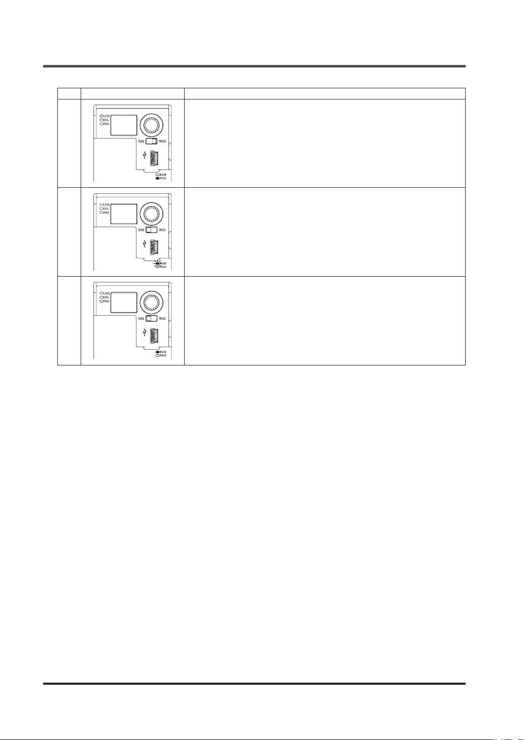
Change Password
Step
Status of indicators and switches
23
Description
Transition to “Quit setting mode.”
Switch the mode selector switch to the “RUN” side.
The operation indicator (green) blinks.
24
25
Press the rotary switch.
The operation indicator (green) status changes to lighting up.
This device transitions to “RUN” status.
© Panasonic Industrial Devices SUNX Co., Ltd. 201666
Page 67
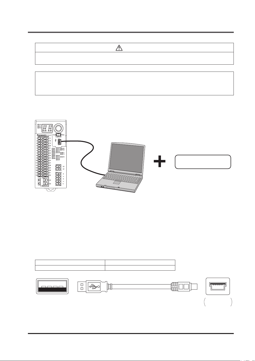
Chapter 5 Software Tool
CAUTION
Connections to this device via USB are assumed to include temporary connections for e.g., settings and diagnoses. Constant connections via USB are not allowed.
<Reference>
.”
SF-C21
software and software tool
The available functions vary depending on the version of
Congurator SF-C
“
For details, refer to “
.”
2-4-1 Version-related Information
5-1 System Conguration
2. USB cable
3. PC
1. Software tools
1. Software tool “Congurator SF-C”
Exclusive for this device.
It is used for logic settings, diagnoses, and preparation of documents.
The software tool is downloadable at our website.
URL: http://www3.panasonic.biz/ac/j/dl_center/software/index.jsp?c=search
In addition to “Narrow down by Part No. / Model No. format”, use “
SF-C21
” for searching.
2. USB cable
Use a USB cable available in the market.
Type of cable Length
USB 2.0 cable (A: miniB) 3m or less
USB A type (male)‒ USB miniB type (5 pin, male)(On the side of PC) On the side
© Panasonic Industrial Devices SUNX Co., Ltd. 2016 67
of this device
Page 68

Software Tool
5-2 Required System Specications
Operation of the software tool “
Conrm that the system in use satises the conditions and all the devices required have been
prepared.
Congurator SF-C
” requires the following environment.
5-2-1 Operating System
Microsoft Windows Vista (32 bit / 64 bit), Windows 7 (32 bit / 64 bit), Windows 8 (32 bit / 64 bit),
Windows 8.1 (32 bit / 64 bit).
The user to be logged in must be specied as “Administrator” or “Power User”.
5-2-2 PC Specications
Hardware specications recommended by Windows.
Fixed disk: Free space of 200 MB or more
USB port
5-3 Installation
Double-click downloaded “ConguratorSF-C_v***”.
Install the program according to the instruction of the installation program.
This installation program requires two installations: installation of software tool and installation
of USB driver for this device.
If a warning message for Windows, e.g., “User account control” or “Publisher of the driver software cannot be veried”, may be displayed before the completion of installation, such a message does not cause any problem. Proceed to the next step.
Installing the USB driver is completed automatically when this device is connected to the PC.
5-4 Uninstallation
Uninstall the following 2 items:
Step 1 Congurator SF-C
Step 2 Windows Driver Package - SF-C20(usbser) Ports(11/15/2007 **)
Select “
Start
Control Panel
” → “
Program and Features
” → “
© Panasonic Industrial Devices SUNX Co., Ltd. 201668
”, and then uninstall them.
Page 69
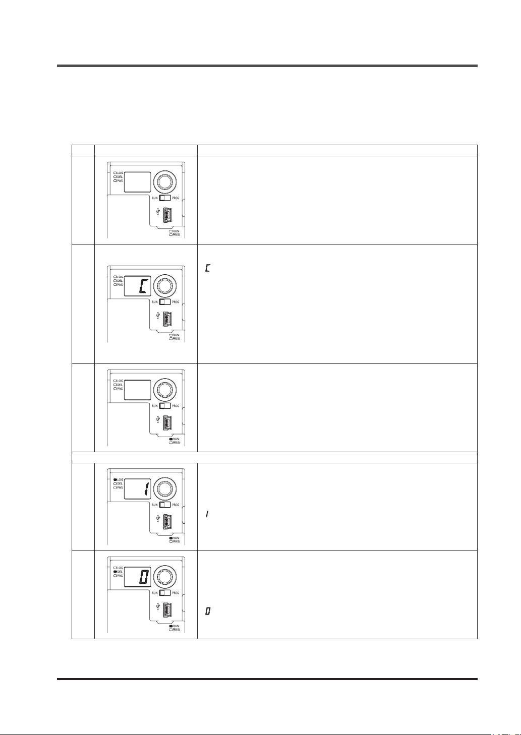
Connection of this Device and a PC
5-5 Connection of this Device and a PC
5-5-1 Connection to “Monitor Mode”
To recognize this device by connecting it to a PC, perform the following procedure:
Step
Status of indicators and switches
1
Power: OFF
Mode selector switch: RUN side
With the internal power supply and external power supply turned OFF, connect this device with a PC via the USB cable.
Turn ON the power supply.
“ ” is displayed in the 7-segment indicator (red).
All the other indicators turn OFF.
Description
2
3
4
5
*: If an error message, for example, “Your USB device is not recognized,” is
displayed in the PC, plug and unplug the USB connector, or turn ON the
power supply again. This prevents displaying the message.
Press the rotary switch.
*: If the connection is made for the rst time, press the rotary switch after the
completion of USB driver installation.
The device enters “Monitor mode.”
The operation indicator (green) lights up.
In “Monitor mode,” the software tool is used to read data from and monitor
this device.
“Monitor mode” prevents writing data into this device.
When writing data into this device, refer to Procedure “
“Transfer Mode”
Press the rotary switch.
The logic No. currently set is displayed in the 7-segment indicator (red).
Logic selection indicator (orange) lights up.
“ : Overall stop control” is set at factory.
Rotate the rotary switch.
The currently set No. for OFF delay time is displayed in the 7-segment indicator (red).
Delay selection indicator (orange) lights up.
“ : 0 sec.” is set at factory.
”.
5-5-2 Connection to
Rotating the rotary switch returns to No.1.
The procedure above is enabled either before or after the activation of the software tool that is
described in the next section.
© Panasonic Industrial Devices SUNX Co., Ltd. 2016 69
Page 70
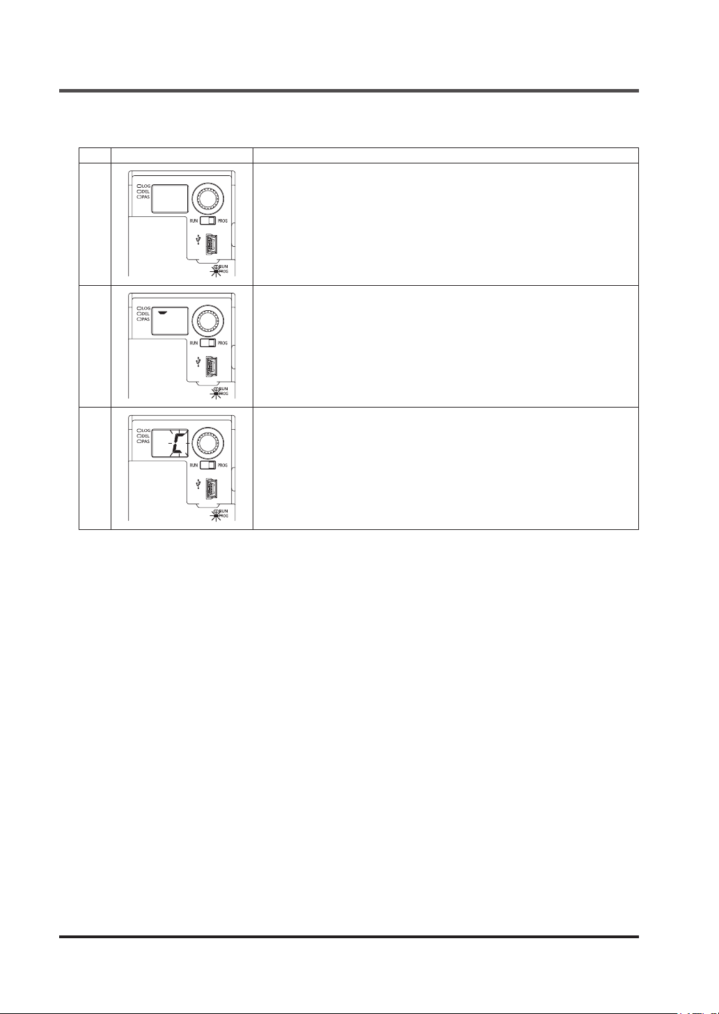
Connection of this Device and a PC
5-5-2 Connection to “Transfer Mode”
Step
Status of indicators and switches
When this device is put in “Monitor mode,” turn the mode selector switch to
the “PROG” side.
The operation indicator (green) turns OFF.
1
The setting indicator (orange) blinks.
This device automatically transitions to “Indicator ON conrmation.”
Individual segments of the 7-segment indicator (red) light up one by one.
Description
2
3
Check for an error code displayed in the 7-segment indicator (red).
Press the rotary switch.
The device enters “Transfer mode.”
“Transfer mode” disables setting operation on the side of this device.
The software tool is used, for example, to transfer customizable logic to this
device and change password.
“Transfer mode” puts all control outputs in OFF status.
© Panasonic Industrial Devices SUNX Co., Ltd. 201670
Page 71
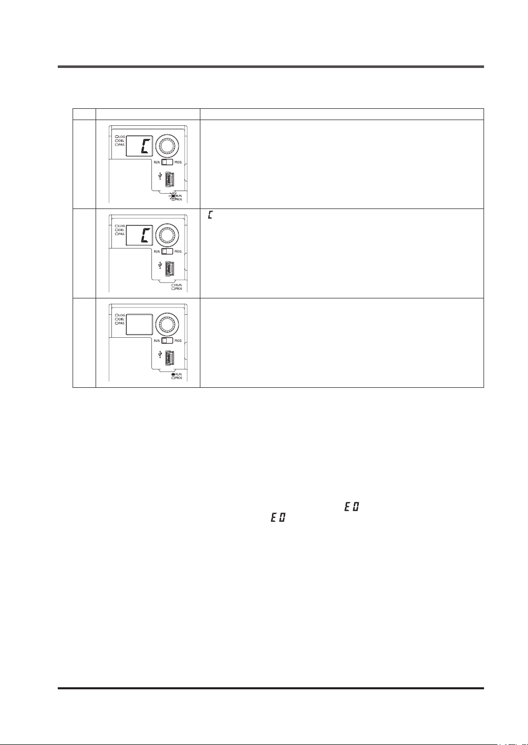
Connection of this Device and a PC
5-5-3 Setting to “Monitor Mode” after the End of Transfer
Step
Status of indicators and switches
1
2
When this device is put in “Transfer mode,” turn the mode selector switch to
the “RUN” side.
The operation indicator (green) blinks.
Press the rotary switch.
“ ” is displayed in the 7-segment indicator (red).
All the other indicators turn OFF.
Press the rotary switch.
The device enters “Monitor mode.”
The operation indicator (green) lights up.
Description
3
In “Monitor mode,” the software tool is used to read data from and monitor
this device.
“Monitor mode” prevents writing data into this device.
When writing data into this device again, refer to Procedure “
Connection to “Transfer Mode”
”.
5-5-2
5-5-4 Disconnection of this Device from a PC
When the USB cable is unplugged from this device, it can be disconnected from the PC.
The USB cable can be unplugged except when “logic is being transferred” by the software tool.
When the mode selector switch is turned to the “RUN” side after the USB cable is unplugged,
pressing the rotary switch has this device perform normal operation.
5-5-5 Initialization of this Device
Unplugging the USB cable during writing operation displays “ ” in the 7-segment indicator
(red), putting it in the lockout status. When “ ” is displayed, connect this device to the PC
again and initialize it by referring to “
5-22-1-2 Initialize Settings
”.
© Panasonic Industrial Devices SUNX Co., Ltd. 2016 71
Page 72
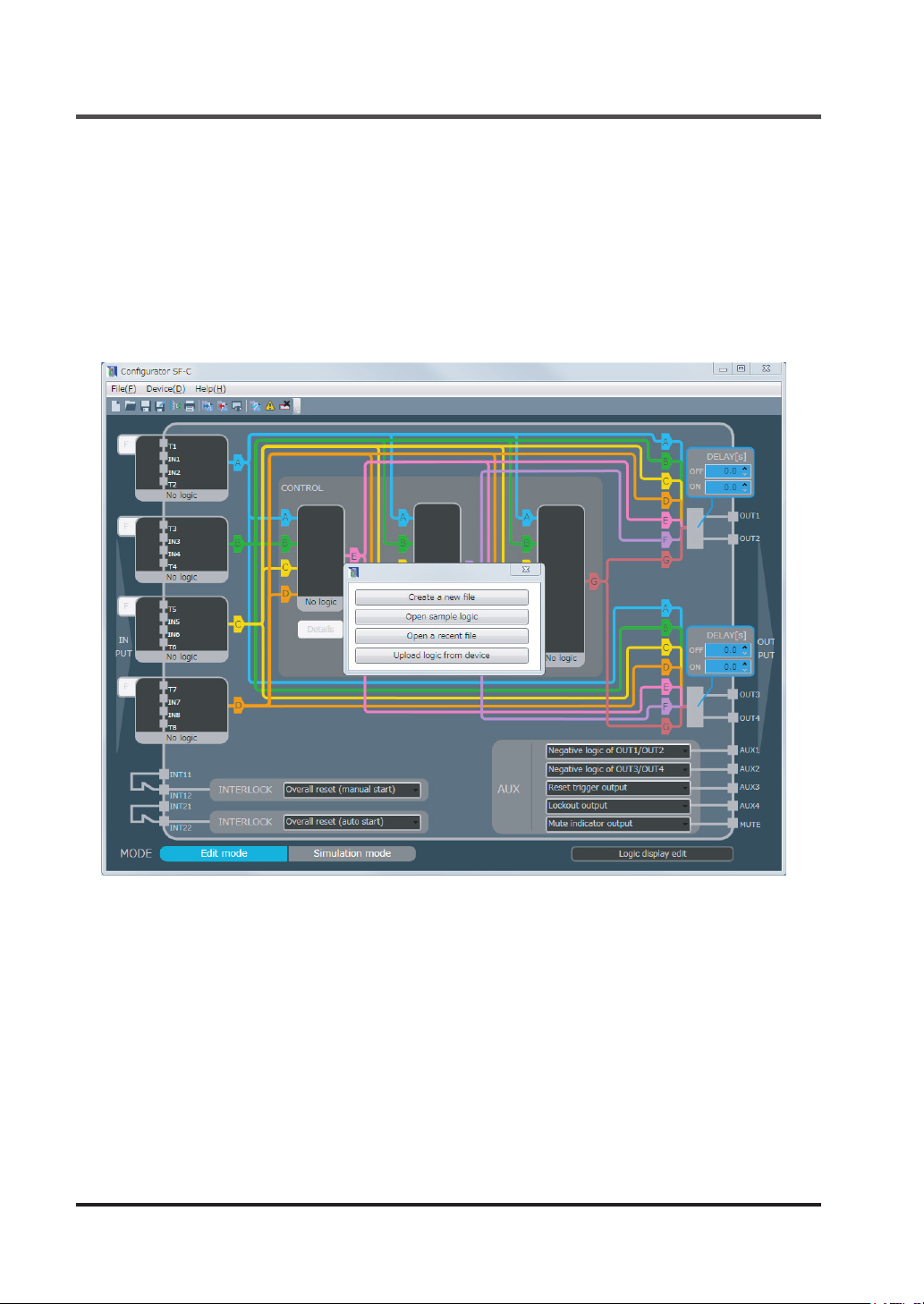
Startup and End of Software Tool
5-6 Startup and End of Software Tool
5-6-1 Startup Software Tool
Startup the software tool “
Step 1 Click the “Start” button in Windows.
Step 2 From All Programs, go to “Panasonic-ID SUNX Safety” and “Congurator SF-C” in or-
der, and then select Congurator SF-C.
Step 3 Starting up the software tool “
tion menu.
Congurator SF-C
Congurator SF-C
” according to the procedure below.
” displays the main menu and selec-
From the selection menu, select one of the following four operations:
● Create a new le
● Open sample logic
● Open a recent le
● Upload logic from device
© Panasonic Industrial Devices SUNX Co., Ltd. 201672
Page 73
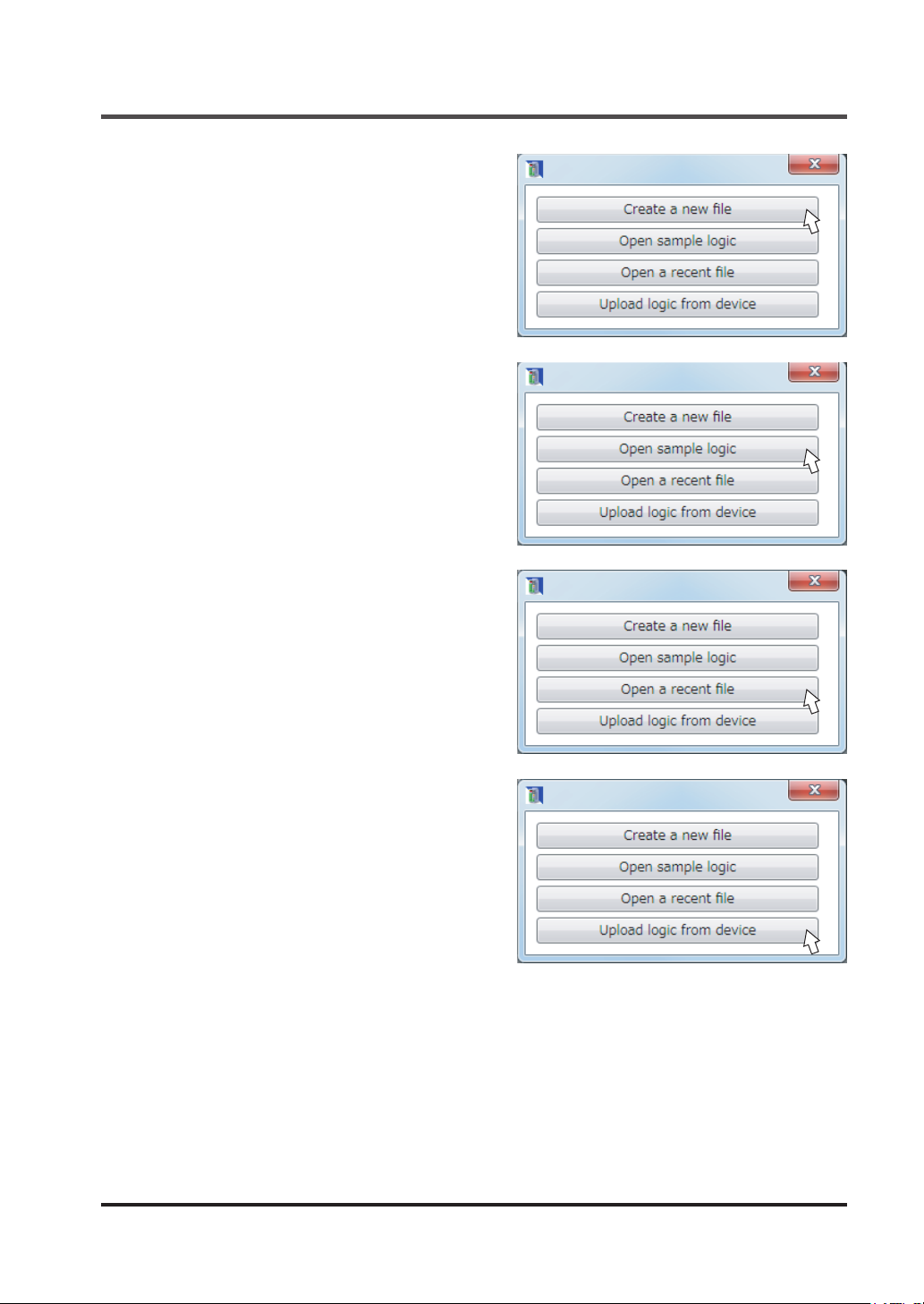
■ To Create a new le
Pressing “
menu disappear, making the main screen clear.
Free logics can be created.
■ To Open sample logic
Pressing “
“Open sample logic” screen. Eight preset logics
provided to this device can be used as sample
logics.
Select one from preset logics No.1 to No.8.
Sample logics are revised to create logics.
■ To Open les saved
Pressing “
“Open le” screen. Select a le to be opened.
Create a new le
Open sample logic
Open a recent file
” has the selection
” displays the
” displays the
Startup and End of Software Tool
■
To obtain a logic from this device in connection
Pressing “
munication with this device, acquiring a logic.
© Panasonic Industrial Devices SUNX Co., Ltd. 2016 73
Upload logic from device
” starts com-
Page 74
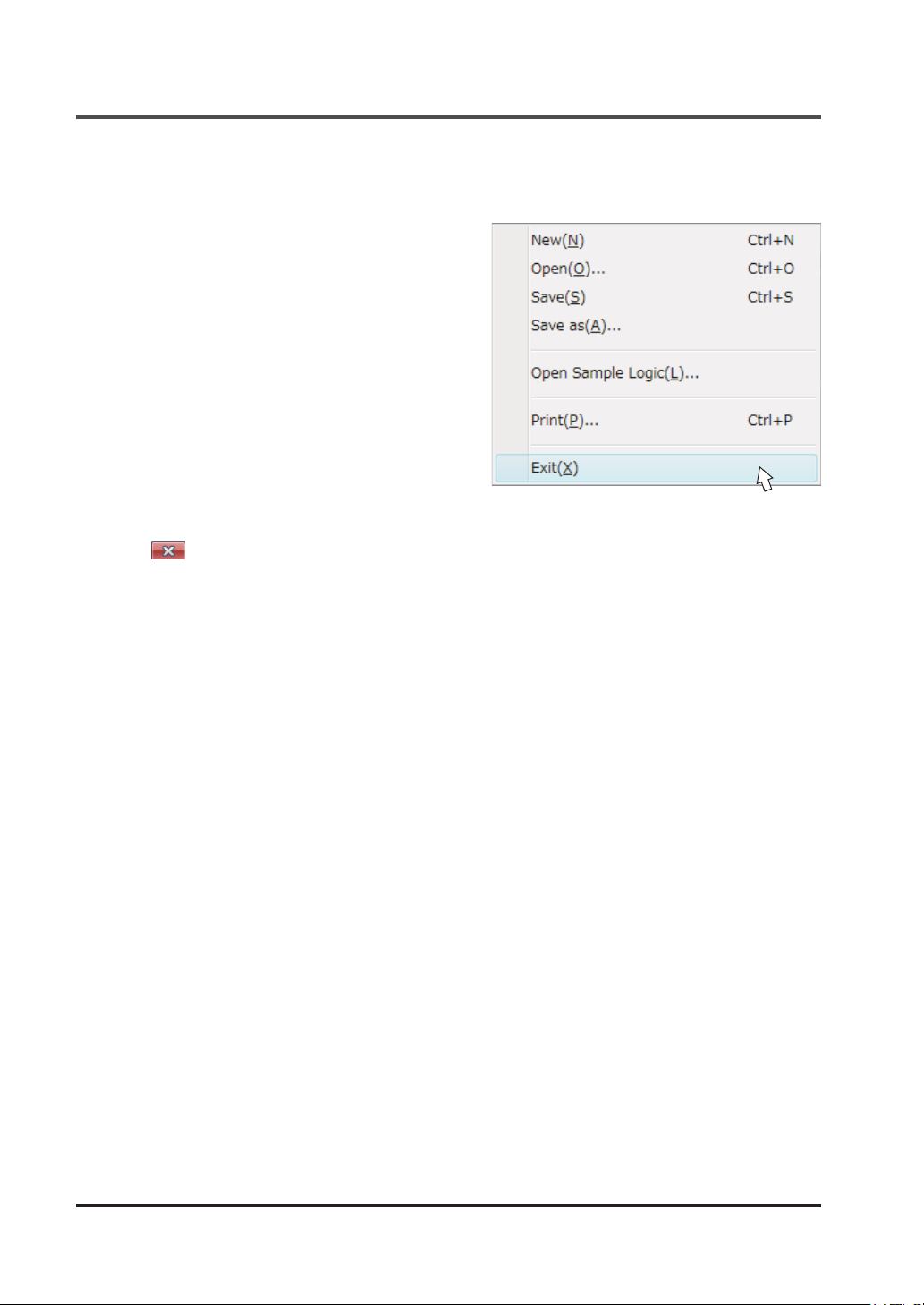
Startup and End of Software Tool
5-6-2 End of Software Tool
To exit the software tool, follow one of the methods below.
<Method 1>
From the menu bar, select “
Exit (X)
“
<Method 2>
Click at the upper right corner of the
screen.
”.
File (F)
” and then
© Panasonic Industrial Devices SUNX Co., Ltd. 201674
Page 75
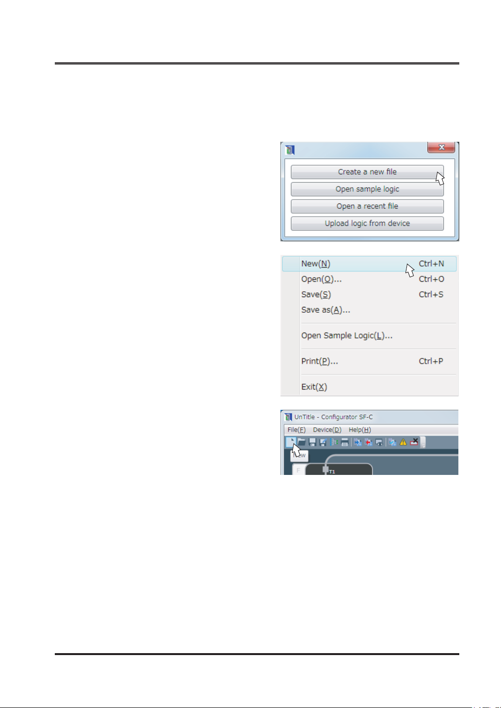
5-7 New / Save / Print of a File
5-7-1 Create New File
New les are created by using one of the following methods.
<Method 1>
When the software tool starts up, select “
a new le
<Method 2>
From the menu bar, select “
New (N)
“
”.
File (F)
”.
Create
" and then
New / Save / Print of a File
<Method 3>
New
Click “
© Panasonic Industrial Devices SUNX Co., Ltd. 2016 75
” icon on the toolbar.
Page 76
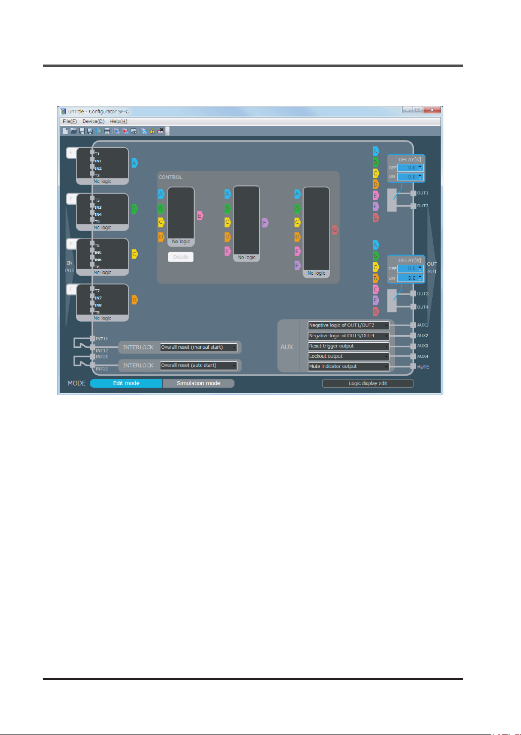
New / Save / Print of a File
When a new le is created according to one of the methods, the main screen is made clear.
© Panasonic Industrial Devices SUNX Co., Ltd. 201676
Page 77
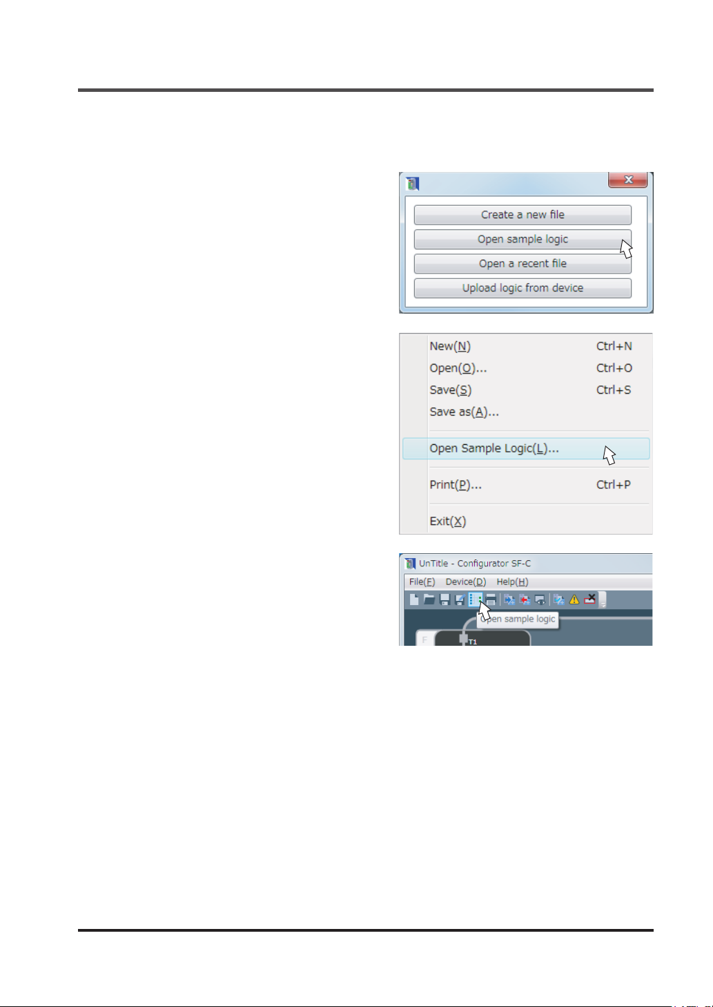
New / Save / Print of a File
5-7-2 Open Sample Logic
Open sample logic is performed according to one of the following methods.
<Method 1>
When the software tool starts up, select “
sample logic
<Method 2>
From the menu bar, select “
Open sample logic (L)
“
”.
File (F)
”.
Open
” and then
<Method 3>
Click the “
bar.
© Panasonic Industrial Devices SUNX Co., Ltd. 2016 77
Open sample logic
” icon on the tool-
Page 78
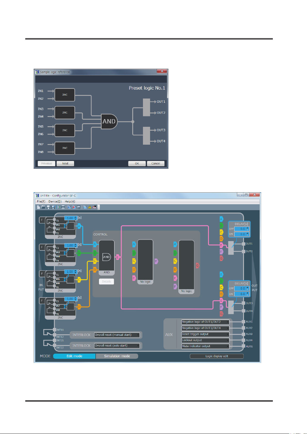
New / Save / Print of a File
When “
and then press “OK”.
The logic is displayed in the main screen.
Open sample logic
” is displayed, select a logic with the “
Previous
” and “
Next
” button,
© Panasonic Industrial Devices SUNX Co., Ltd. 201678
Page 79
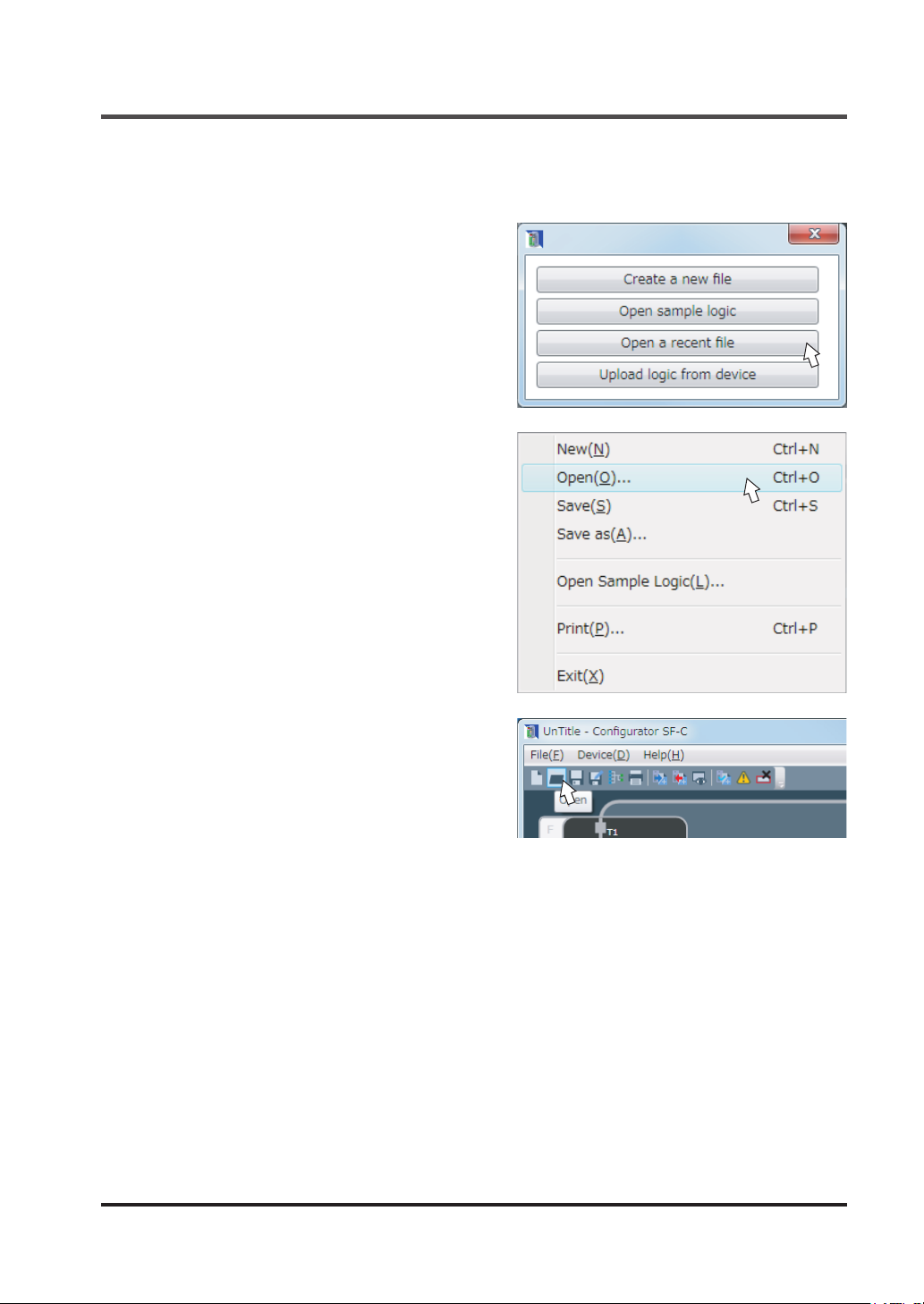
New / Save / Print of a File
5-7-3 Open a Recent File
Existing les are opened by using one of the following methods.
<Method 1>
When the software tool starts up, select “
recent le
<Method 2>
From the menu bar, select “
Open (O)
“
”.
File (F)
”.
Open a
” and then
<Method 3>
Open
Click “
© Panasonic Industrial Devices SUNX Co., Ltd. 2016 79
” icon on the toolbar.
Page 80
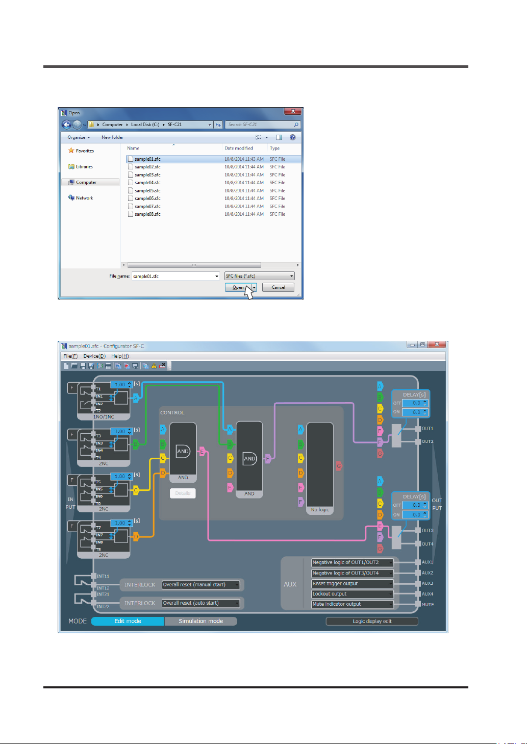
New / Save / Print of a File
When the le selection diagram is displayed, select a le and click “
Opening the le displays a logic in the main screen.
Open (O)
”.
© Panasonic Industrial Devices SUNX Co., Ltd. 201680
Page 81
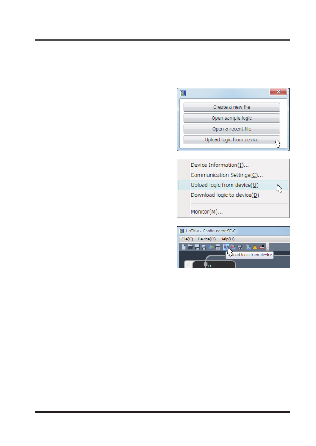
New / Save / Print of a File
5-7-4 Upload Logic from this Device
To obtain logics from this device, one of the following methods is performed.
Connect this device with a PC according to procedure “
<Method 1>
When the software tool starts up, select “
logic from device
<Method 2>
From the menu bar, select “
Upload logic from device (U)
then “
<Method 3>
Click the “
the toolbar.
Upload logic from device
”.
Device (D)
Upload
” and
”.
” icon on
5-5-1 Connection to “Monitor Mode”
”.
© Panasonic Industrial Devices SUNX Co., Ltd. 2016 81
Page 82
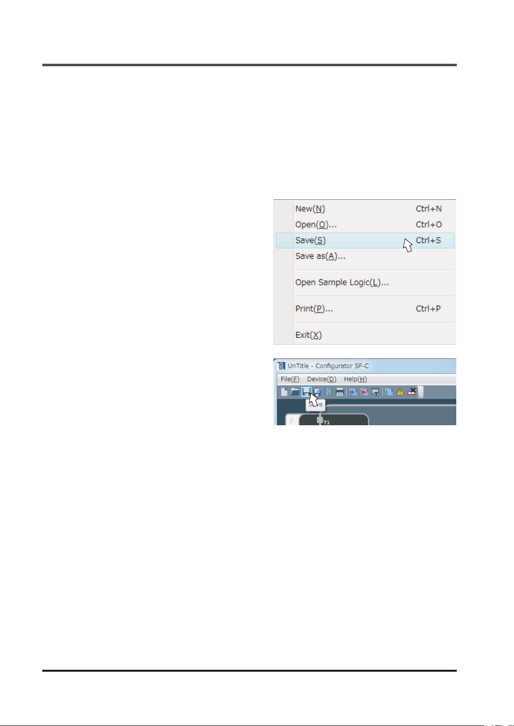
New / Save / Print of a File
5-7-5 Saving a File
Save a logic, to be displayed in the main screen, in the PC as a le.
The le format of the les to be created is specied to be le name “.sfc”.
Select “Save” to save a file to the same file, and select “Save as” to save under a new file
name.
■ Save
Files are saved by one of the following methods:
<Method 1>
From the menu bar, select “
Save (S)
“
”.
File (F)
” and then
<Method 2>
Click the “
Save
” icon on the toolbar.
© Panasonic Industrial Devices SUNX Co., Ltd. 201682
Page 83
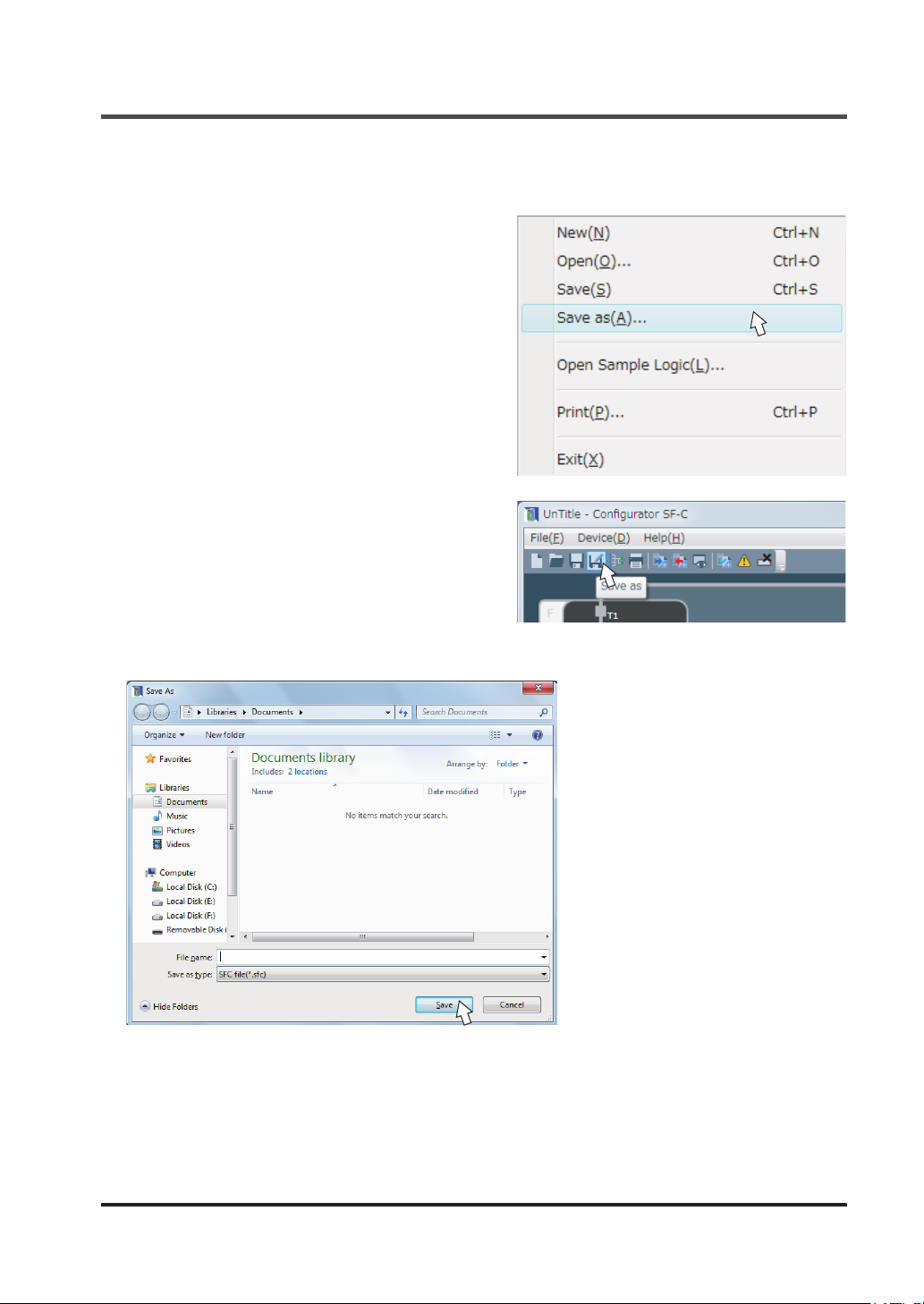
New / Save / Print of a File
■ Save as
Files are saved under new le names by one of the following methods:
<Method 1>
From the menu bar, select “
Save as (A)
“
<Method 2>
Click the “
”.
Save as
” icon on the toolbar.
File (F)
” and then
Specify a place to save the le and the le name, and click “
Save (S)
”.
© Panasonic Industrial Devices SUNX Co., Ltd. 2016 83
Page 84
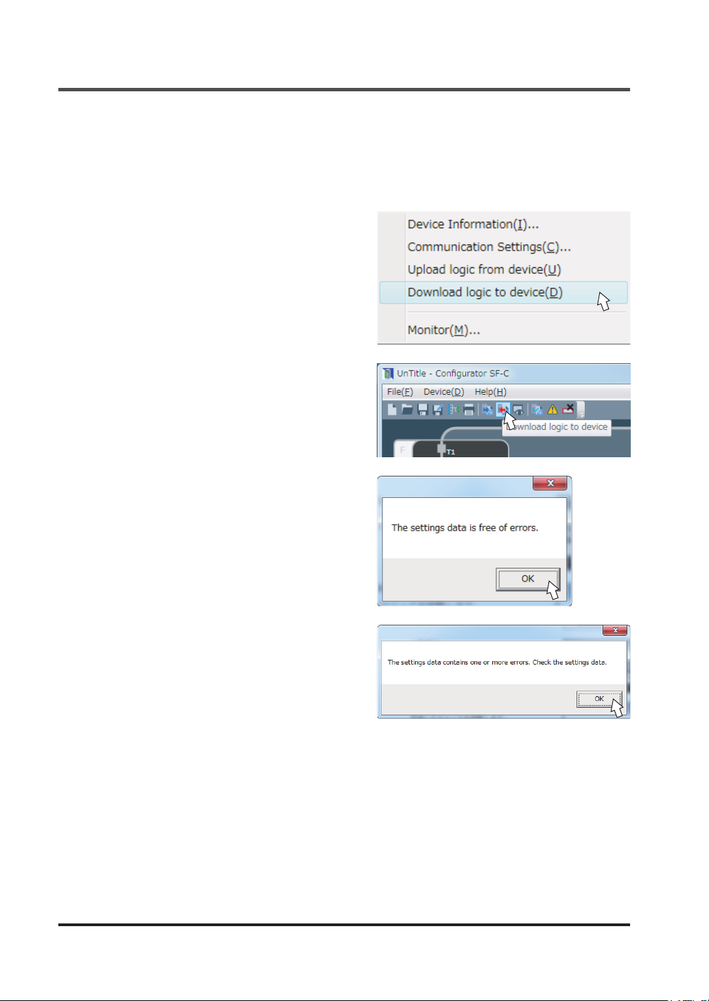
New / Save / Print of a File
5-7-6 Download Logic to Device
Logic is transferred to this device according to the following procedure:
Connect this device to the PC according to the procedures “
Mode”
Step 1
<Method 1>
From the menu bar, select “
Download logic to device (D)
then “
<Method 2>
Click the “
the toolbar.
Step 2 Diagnosing logic
Diagnose the logic created.
This shows a display without error.
Click “OK” and proceed to the next step.
5-5-2 Connection to “Transfer Mode”
” and “
Device (D)
”.
Download logic to device
”.
” and
” icon on
5-5-1 Connection to “Monitor
This shows a display with some error in the logic
created.
Click “OK” to return to the main screen, and then
correct the logic.
The place of an error is highlighted in a red
frame in the main screen.
© Panasonic Industrial Devices SUNX Co., Ltd. 201684
Page 85
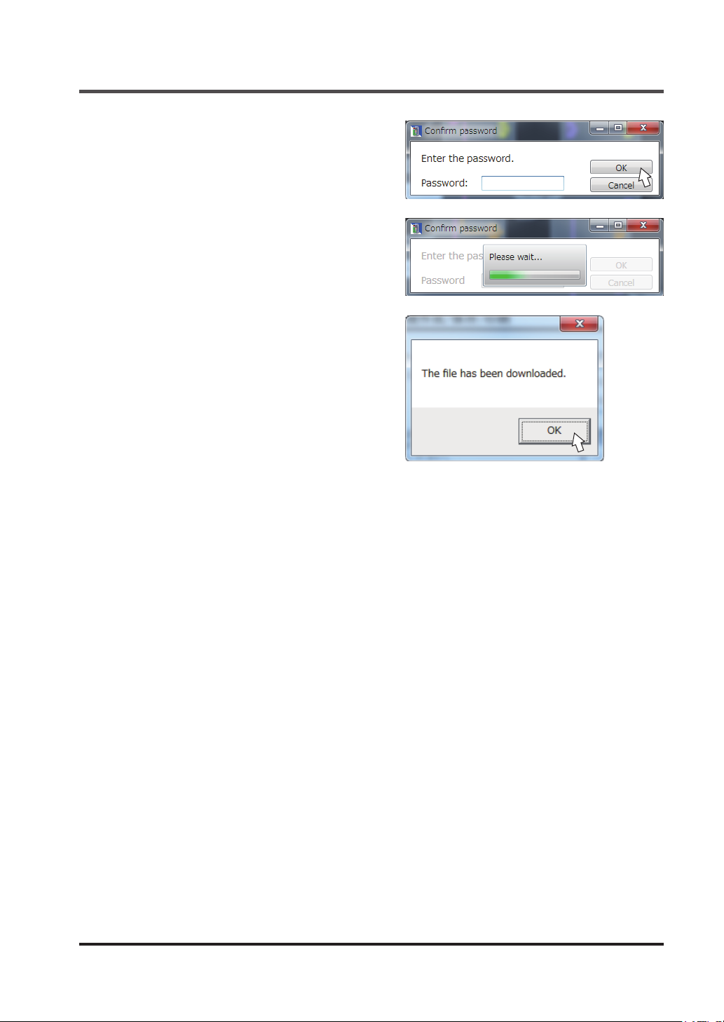
Step 3 Completion of entry and transfer of
password
Enter the password and click “OK”.
Logic is being transferred.
While being transferred, do not remove the USB
cable, or do not turn OFF the power supply.
The le has been downloaded.
Click “OK”.
New / Save / Print of a File
According to the procedures “
“Monitor Mode” after the End of Transfer
5-5-4 Disconnection of this Device from
and “
a PC
”, return this device to the monitor mode
and remove the USB cable.
5-5-3 Setting to
”
© Panasonic Industrial Devices SUNX Co., Ltd. 2016 85
Page 86
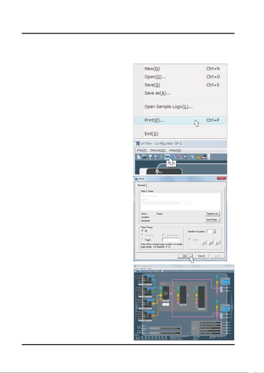
New / Save / Print of a File
5-7-7 Print
Logic is printed by one of the following methods:
<Method 1>
From the menu bar, select “
Print (P)
“
<Method 2>
Click the “
”.
Print
” icon on the toolbar.
File (F)
” and then
When the print dialog is displayed, select a
printer and perform printing.
Preview is displayed on the backside of the
dialog box. The contents can be confirmed
before printing.
© Panasonic Industrial Devices SUNX Co., Ltd. 201686
Page 87
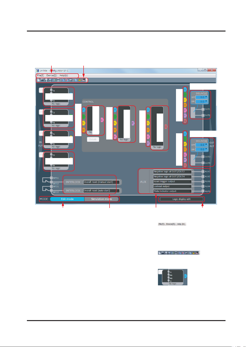
Each Part Name of the Software Tool and Basic Operation
5-8 Each Part Name of the Software Tool and Basic Operation
The main screen of the software tool is comprised of the following elements:
Menu bar
Input block 1
Input block 2
Input block 3
Input block 4
Toolbar
Connection tab 1
Control block 1
Connection tab 2
Control block 2
Connection tab 3
Control block 3
Output block 1
Connection tab 4
Output block 2
Connection tab 5
Mode switching block
Interlock block
Auxiliary output block Logic edit block
■ Menu bar
All the operations and functions of the software tool are
prepared in a menu format according to various applications.
■ Toolbar
Frequently used functions are displayed with icons.
■ Input block
Input devices are selected, and input mismatch time, etc.,
are set.
Clicking the input block opens “Input select”.
© Panasonic Industrial Devices SUNX Co., Ltd. 2016 87
Page 88
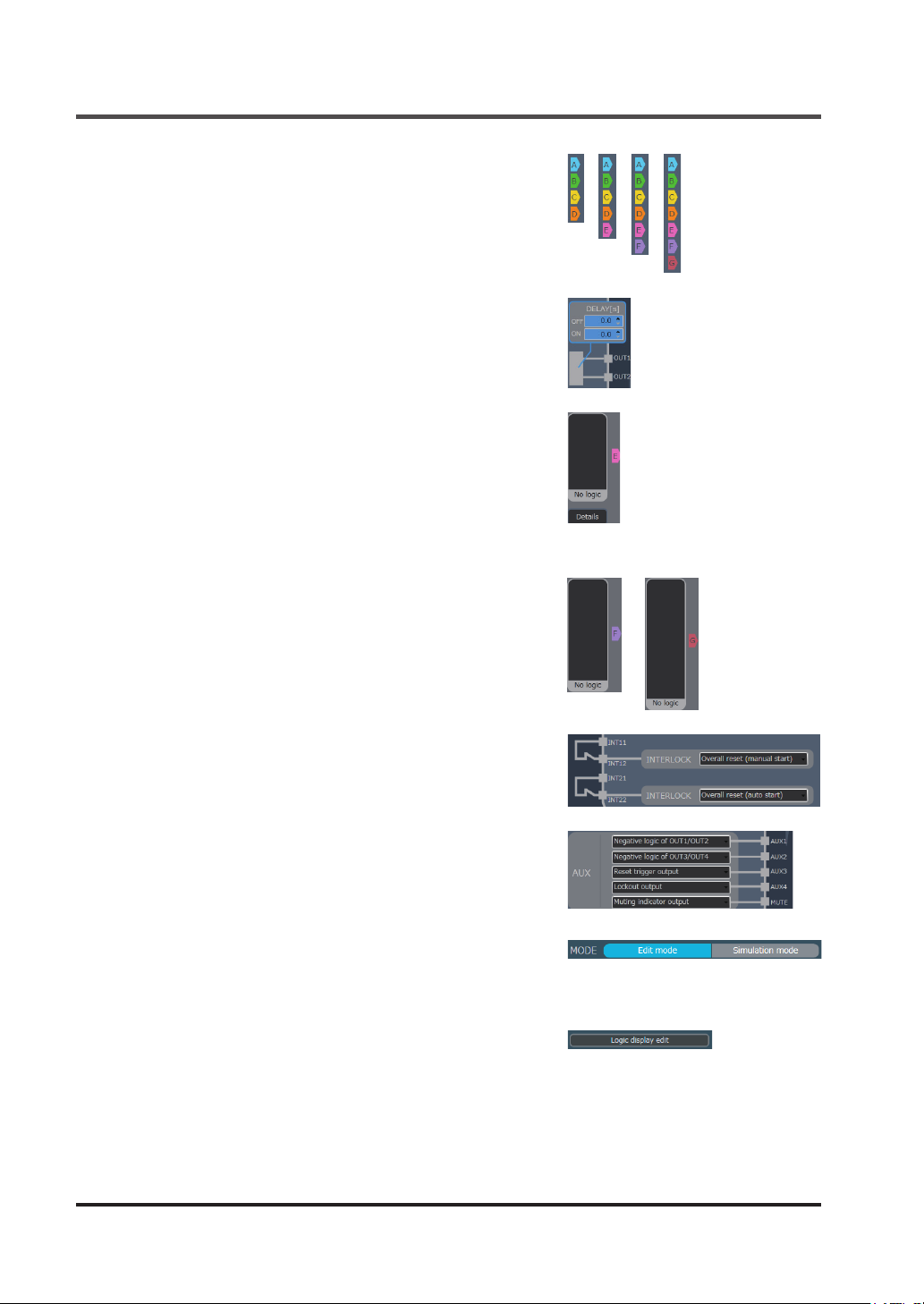
Each Part Name of the Software Tool and Basic Operation
■ Connection tab
Clicking this tab connects a circuit.
■ Output block
ON delay time and OFF delay time for control output are
set.
■ Control block 1
Required control is selected from from AND, OR, parallel
muting control, sequential muting control, two-hand control, and input select.
Selecting parallel muting control or sequential muting control activates detailed settings, allowing required detailed
items to be set in muting.
■ Control block 2 / 3
Required logic is selected from AND, OR and no logic.
■ Interlock block
Overall reset, partial reset (manual start) and partial reset
(auto start) are carried out.
■ Auxiliary output block
Settings of auxiliary output can be changed. The results of
the monitoring of input devices, internal logic, etc., are set
as auxiliary output.
■ Mode switching block
Switching is performed between edit mode and simulation
mode.
■ Logic edit block
Display of customizable logic No. is set.
© Panasonic Industrial Devices SUNX Co., Ltd. 201688
Page 89

Creating and Editing a Logic, and Saving a File and Transferring it to this Device
5-9 Creating and Editing a Logic, and Saving a File and Transferring it to
this Device
5-9-1 Creating and Editing Logic
The following methods are available to create and edit logic.
■ Creating a new logic
A logic is created according to “
■ Open and edit a logic according to Open sample logic
Sample logic is opened and edited according to “
When a logic uses “Parallel muting,” “Sequential muting,” “Two-hand control,” and “Input select,”
editing an applicable logic by opening it is easier than by creating a new logic.
■ Open a recent le and edit it
When a logic has already been created, open a recent le and edit it according to “
a Recent File
■ Obtain a logic from this device and edit it
According to “
this device, and edit it.
”.
5-7-4 Upload Logic from this Device
5-7-1 Create New File
5-7-2 Open Sample Logic
”.
”.
5-7-3 Open
”, obtain the logic, which is being used in
5-9-2 Saving a Logic File and Transferring it to this Device
■ Saving a logic in the PC
After a logic is created and edited, it is saved in the PC as a le according to “
File
”.
■ Transfer a logic to this device
After a logic is created and edited, it is transferred to this device according to “
Logic to Device
”.
5-7-5 Saving a
5-7-6 Download
© Panasonic Industrial Devices SUNX Co., Ltd. 2016 89
Page 90
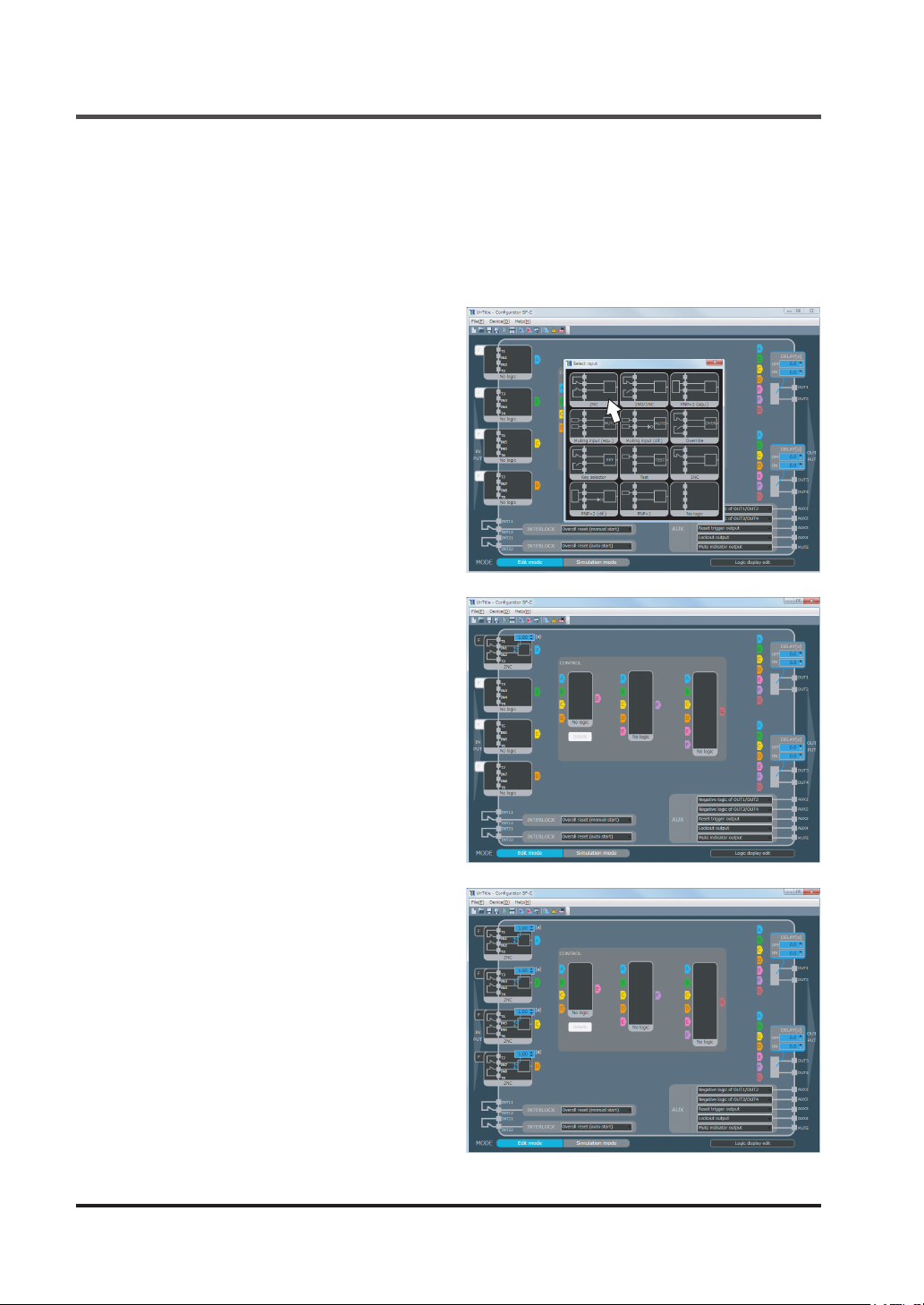
Create a Logic
5-10 Create a Logic
5-10-1 Create a Logic
As an example, sample logic No.1 is created from the new screen.
5-10-1-1 Set Input Lock
Click input block 1 and open “Input select”.
2NC
Click “
Selected “2NC” is set in input block 1.
” at the upper left portion.
Similarly set input blocks 2, 3 and 4.
Set all input blocks to “2NC”.
© Panasonic Industrial Devices SUNX Co., Ltd. 201690
Page 91
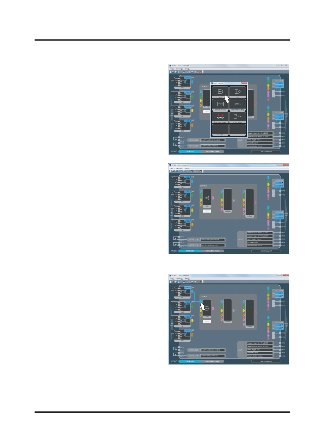
5-10-1-2 Set Control Block 1
Click control block 1 and open “Select control”.
AND
Click “
Selected “AND” is set in control block 1.
” at the upper left portion.
Create a Logic
5-10-1-3 Create a Circuit
Click “A” of connection tab 1 to connect it to
A of input block 1.
© Panasonic Industrial Devices SUNX Co., Ltd. 2016 91
Page 92
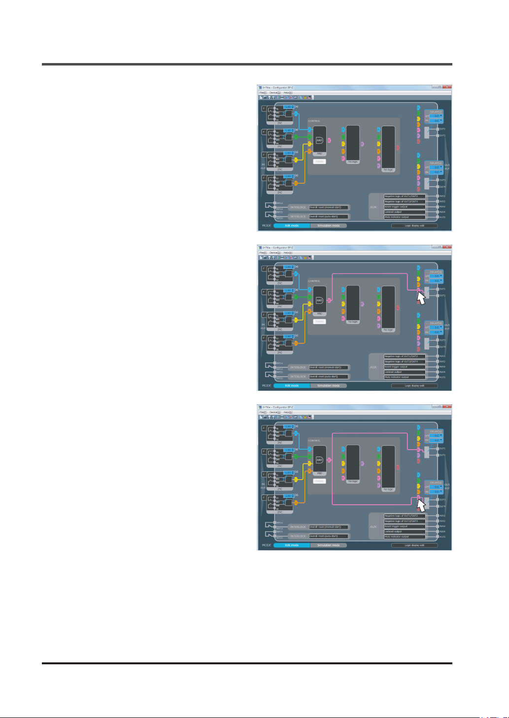
Create a Logic
Similarly click “B” of connection tab 1 to
connect it to B of input block 2. Click “C” to
connect it to C of input block 3. Click “D” to
connect it to D of input block 4.
Click “E” of connection tab 4 to connect it to
E of connection tab 1.
Click “E” of connection tab 5 to connect it to
E of connection tab 1.
Sample logic No.1 is created completely.
© Panasonic Industrial Devices SUNX Co., Ltd. 201692
Page 93
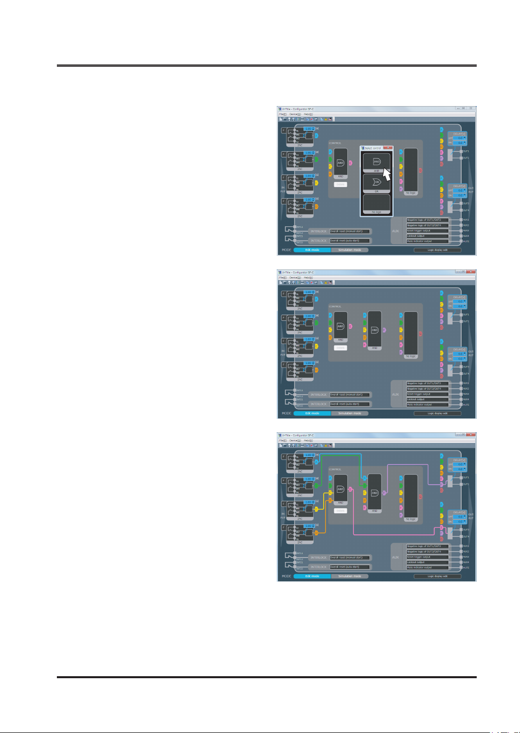
5-10-2 Example of a Logic Using Control Block 1 / 2
Click control block 2 and open “Select control”.
AND
Click “
Selected “AND” is set in control block 2.
”.
Create a Logic
● Click “C” of connection tab 1 to connect it
to C of input block 3. Click “D” to connect it
to D of input block 4.
● Click “A” of connection tab 2 to connect it
to A of input block 1. Click “B” to connect it
to B of input block 2.
● Click “F” of connection tab 4 to connect it
to F of connection tab 2.
● Click “E” of connection tab 5 to connect it
to E of connection tab 1.
The following logic is created.
● Output block 1 outputs the AND of input
blocks 1 and 2.
● Output block 2 outputs the AND of input
blocks 3 and 4.
© Panasonic Industrial Devices SUNX Co., Ltd. 2016 93
Page 94
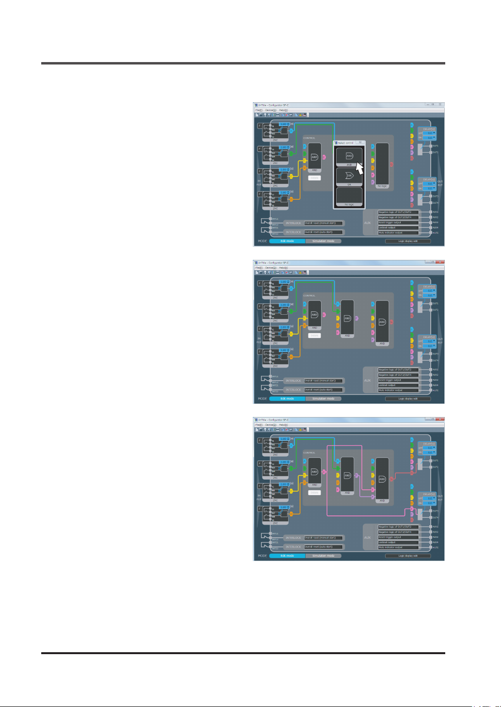
Create a Logic
5-10-3 Example of a Logic Using Control Block 1 / 2 / 3
For the creation of a logic of control block
1/2, refer to “
Using Control Block 1 / 2
Click control block 3 and open “Select control”.
AND
Click “
Selected “AND” is set in control block 3.
5-10-2 Example of a Logic
”.
”.
Click the following portions to perform wiring.
● Click “E” of connection tab 3 to connect it
to E of connection tab 1. Click “F” to connect it to F of connection tab 2.
● Click “G” of connection tab 4 to connect it
to G of connection tab 3.
● Click “E” of connection tab 5 to connect it
to E of connection tab 1.
The following logic is created.
● Output block 1 outputs the AND of control
blocks 1 and 2.
● Output block 2 outputs the AND of input
blocks 3 and 4.
© Panasonic Industrial Devices SUNX Co., Ltd. 201694
Page 95
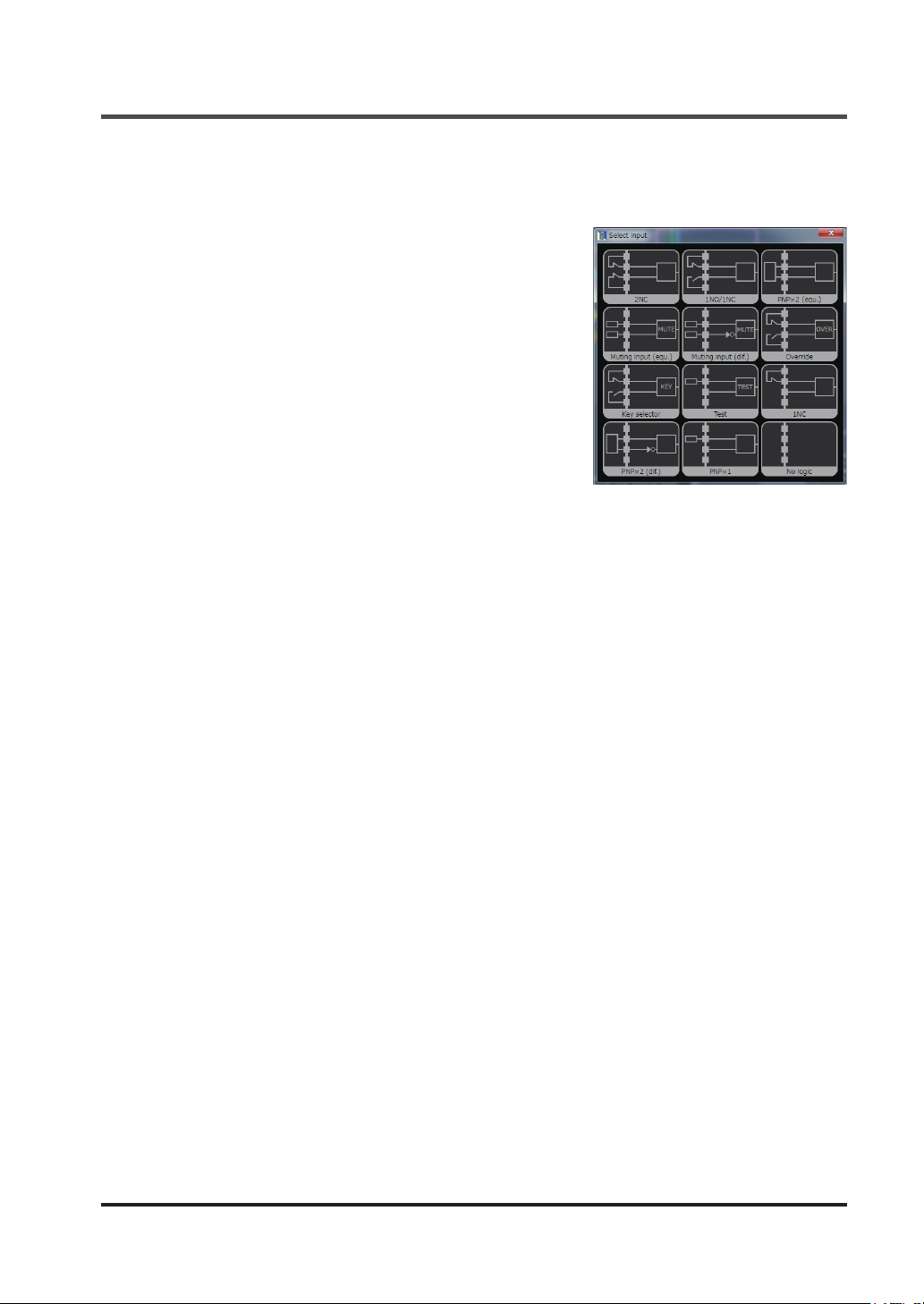
Input Select
5-11 Select Input
5-11-1 Types of Inputs
■ 2NC
Used to connect the safety device of 2NC contact output.
■ 1NO / 1NC
Used to connect safety device of 1NO / 1NC contact output.
■ PNP×2 (equ.)
Used to connect safety devices (PNP semiconductor output × 2). The safety device to be used is a type that turns
“ON-OFF” two outputs simultaneously.
■ Muting input (equ.)
Used as an input of mute sensor when it is selected as “Parallel muting” or “Sequential muting”
in control block 1.
This connects two mute sensors (equ.), each of which has two NO contacts or output [PNP
semiconductor output].
When “Sequential muting” is set in control block 1, both “Muting input (equ.)” and “Muting input
(dif.)” cannot be used at a time.
■ Muting input (dif.)
Used as the input of mute sensor when it is selected as “Parallel muting” or “Sequential muting”
in control block 1.
This connects two mute sensors (dif.), each of which has NO and NC contacts or output [PNP
semiconductor output].
When “Sequential muting” is set in control block 1, both “Muting input (equ.)” and “Muting input
(dif.)” cannot be used at a time.
■ Override
Used as the input of override switch when it is selected as “Parallel muting” or “Sequential muting” in control block 1.
Connects a momentary type switch for 1NO / 1NC contact.
■ Key selector
Used as the input of key selector switch when “Input select” is selected in control block 1.
Connects an alternate type key switch (with a forced breaking contact) for 1NO / 1NC.
■ Test
When test input is effective, the control output is turned into OFF status.
The switch for 1NC contact or PNP semiconductor output (normally set to ON) is connected.
● Contact “Close” or output ON : Test input invalid
● Contact “Open” or output OFF : Test input valid
The input block with this input selected is not connected to connection tab, control block, or output block. If connected, the input block is judged to be erroneous by the software tool.
© Panasonic Industrial Devices SUNX Co., Ltd. 2016 95
Page 96
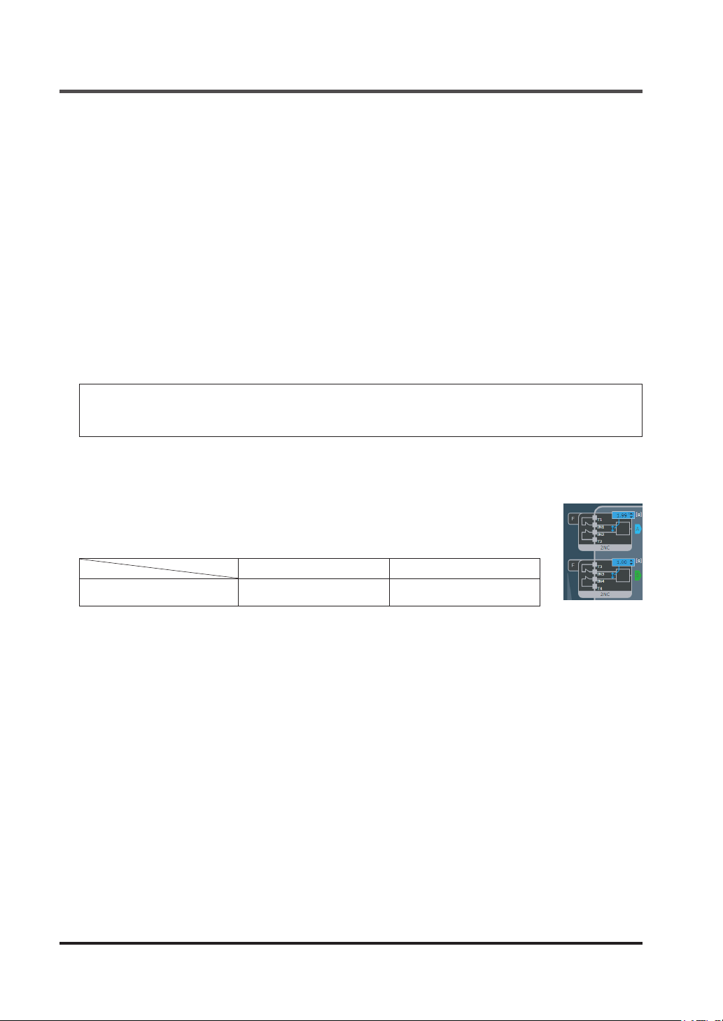
Input Select
■ 1NC
Used to connect the safety device of 1NC contact output. In this case, the category of the sys-
tem including this device is specied to be category 2 or less.
■ PNP×2 (dif.)
Used to connect safety devices (PNP semiconductor output × 2). The safety device to be used
is a type that turns “ON-OFF” two outputs alternately.
■ PNP×1
Used to connect a safety device (PNP semiconductor output × 1). In this case, the category of
the system including this device is specied to be category 2 or less.
■ No logic
If the number of safety devices in connection is less than 4, they are used for unused input
block. If a safety device is connected, the operation is not reected.
<Reference>
For the connectable input blocks, and combinations of them with control blocks, refer to “
Conguration Check
”.
5-20
5-11-2 Setting of Contact Input Mismatch Allowable Time
Setting “2NC” or “1NO / 1NC” in the input block displays a small blue window.
Mismatch allowable time is set between two inputs by using up-down arrows in
the input block or by direct entry.
Settable range Initial setting
Input mismatch allowable time
0 (unlimited) to
60 sec. (in units of 0.01 sec.)
1 sec.
© Panasonic Industrial Devices SUNX Co., Ltd. 201696
Page 97
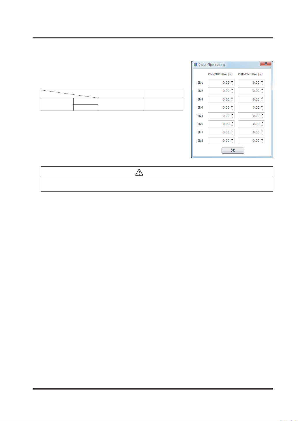
Input Select
5-11-3 Input Filter Time Setting
Clicking “F” in the input block opens “Input lter time.”
Input lter time for ON to OFF and OFF to ON is set for the
prevention of erratic operations caused by input chattering
and noise.
Settable range Initial setting
Input lter time
ON - OFF
OFF - ON
0 to 1 sec.
(in units of 0.01 sec.)
0 sec.
CAUTION
If the input lter time (ON - OFF) is set, the OFF response time for control output becomes "10ms
+ input lter time (ON - OFF)" or less.
© Panasonic Industrial Devices SUNX Co., Ltd. 2016 97
Page 98
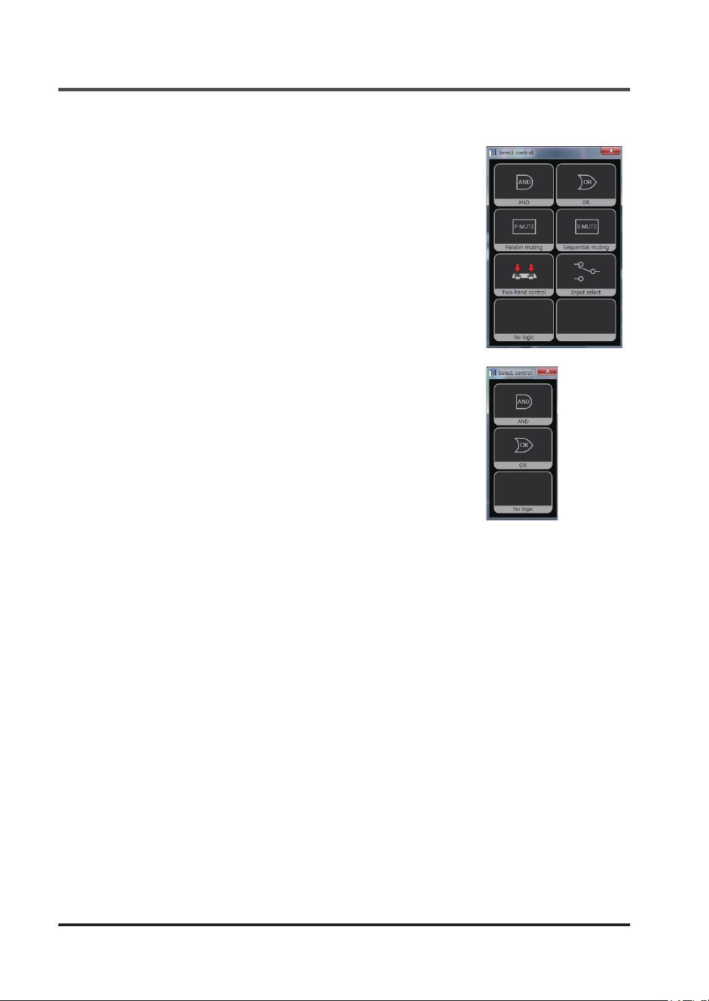
Select Control
5-12 Select Control
Selectable control in control block 1 / 2 / 3
■ AND
“AND” of inputs connected to the control block is output.
Two or more inputs are connected.
The input blocks in which muting input (equ.), muting input (dif.),
override, key selector or test has been set cannot be connected.
■ OR
“OR” of inputs connected to the control block is output.
■ No logic
Selected when the control block is unused.
Selectable control only in control block 1
■ Parallel muting
Used when “Parallel muting” is performed.
In the connected muting input block, the IN with the smaller number is set as muting input A,
and the IN with the larger number is set as muting input B.
If input block 3 is set and connected as a muting input, IN5 becomes muting input A and IN6 becomes muting input B.
■ Sequential muting
Used when “Sequential muting” is performed.
In the two connected muting input blocks, INs are set as muting input A, muting input B, muting
input C and muting input D in the ascending order of the IN number.
If input blocks 2 and 3 are set and connected as muting inputs, IN3 becomes muting input A,
IN4 becomes muting input B, IN5 becomes muting input C, and IN6 becomes muting input D.
When “Sequential muting” is selected, both “Muting input (equ.)” and “Muting input (dif.)” cannot
be used for input block at a time.
© Panasonic Industrial Devices SUNX Co., Ltd. 201698
Page 99

Select Control
■ Two-hand control
Used to congure Two-hand control devices of ISO 13851 (JIS B9712).
■ Select input
When output, state is switched between the two input blocks.
Three input blocks are connected to control blocks, and one of them is specied to be “key selector”.
If input block 2 and input block 4 are set as inputs to be selected and input block 3 is set and
connected to the key selector input, input block 2 is selected when IN5 is OFF and IN6 is ON
and input block 4 is selected when IN5 is ON and IN6 is OFF.
<Reference>
For the connectable input blocks, and combinations of them with control blocks, refer to “
Conguration Check
”.
5-20
© Panasonic Industrial Devices SUNX Co., Ltd. 2016 99
Page 100

Interlock Block
5-13 Interlock block
Reset operation of this device is set.
Click and select the interlock block.
The combinations of overall resets and partial resets are
unavailable.
● Overall reset
● Partial reset (auto start) + Partial reset (auto start)
● Partial reset (auto start) + Partial reset (manual start)
● Partial reset (manual start) + Partial reset (auto start)
● Partial reset (manual start) + Partial reset (manual start)
■ Overall reset
The outputs of two systems of this device are reset by one operation.
● Manual reset : Momentary type switch is connected to between INT11 and INT12.
Switching the switch contact from “Closed to Open” performs reset operation.
● Auto reset : Short-circuit is generated between INT21 and INT22.
If INT21-INT22 is not short-circuited when power is turned ON, manual reset is automatically
selected.
■ Partial reset
Each of the outputs of two systems of this device is reset individually.
● Manual reset : Momentary type switch is connected to between INT11 and INT12 and be-
tween INT21 and INT22. Switching the switch contact from “Closed to Open”
performs reset operation.
● Auto reset : Short-circuit is generated between INT11 and INT12 and between INT21 and
INT22.
Also refer to “
3-4 Interlock (Reset)
”.
© Panasonic Industrial Devices SUNX Co., Ltd. 2016100
 Loading...