

Page 1
Setup Guide
Operating Instructions
DVD Stereo System
STEP
STEP
STEP
Model No.
SC-NC9
SC-NC6
Positioning the speakers
Connecting the speakers
Television, antenna and AC mains lead connections
STEP
STEP
EB
The remote control
QUICK SETUP
Once all the connections are completed, kindly read
the Operations Guide for playback operations.
RQTX0073-B
Page 2
2
RQTX0072
30
o
12 0
o
30
o
(S B -W NC 9)
(S B -P S9 )
(S B -P S9 )
(S B -P F9 /
SB - PF 6)
(S B -P F9 /
SB - PF 6)
(S B -P C9 )
Simple setup
SC-NC9
SC-NC9
STEP
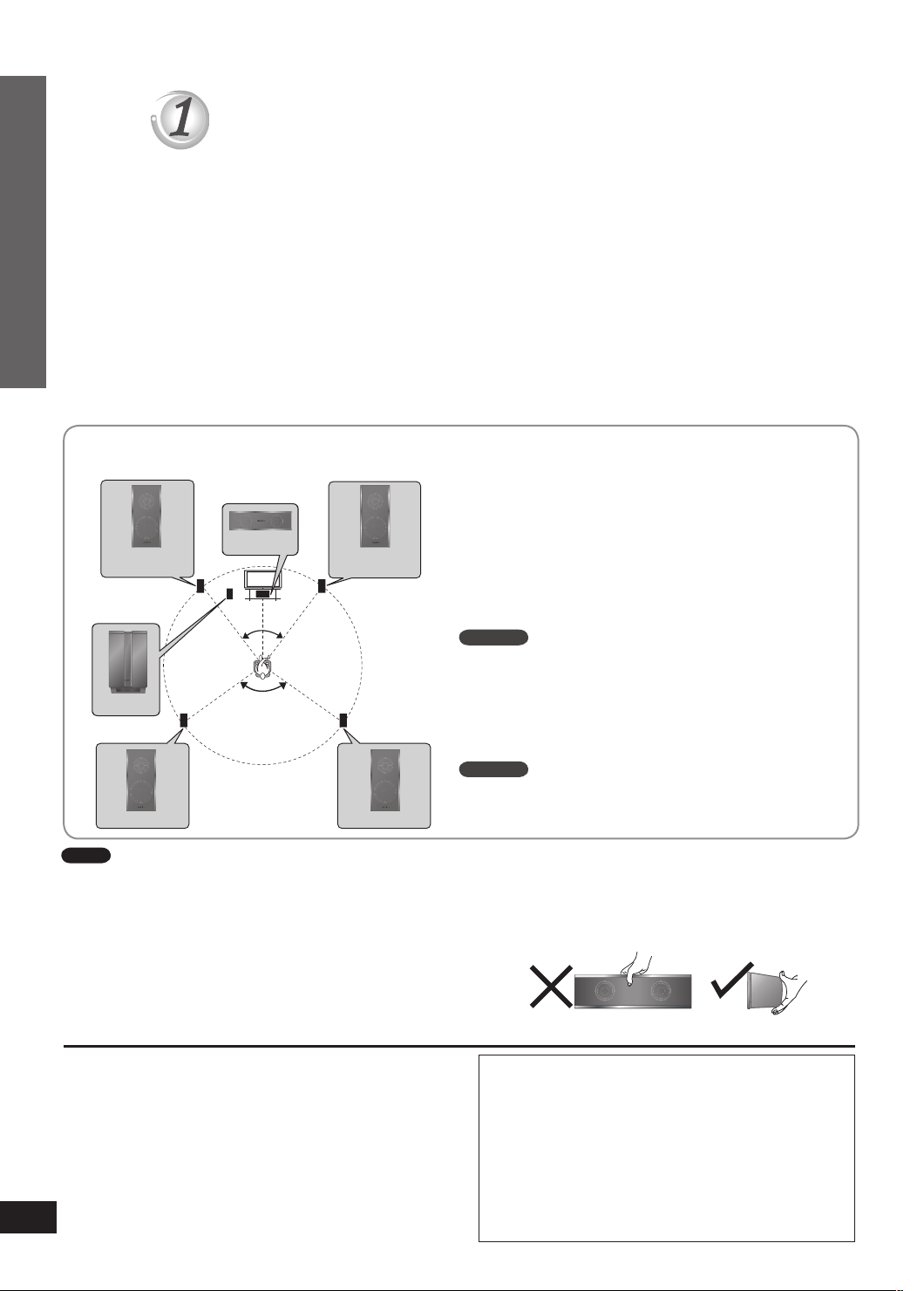
Positioning the speakers
Positioning for best effect
How you set up your speakers can affect the bass and the sound field. Note the following points.
Place speakers on flat secure bases.
•
Placing speakers too close to floors, walls, and corners can result in excessive bass. Cover walls and windows
•
with a thick curtain.
Keep your speakers at least 10 mm away from the system for proper ventilation.
•
The angles in the diagrams are approximate.
•
Left and right speakers are interchangeable, but front and surround speakers are not.
•
Use only the supplied speakers
Using other speakers can damage the unit and sound quality will be negatively affected.
•
Set the speakers up on an even surface to prevent them from falling. Take proper precautions to prevent the
•
speakers from falling if you cannot set them up on an even surface.
Place the front, center, and surround speakers at approximately the same distance from the seating position.
Front speakers
Speakers are designed identically so that no left or
right channel orientation is necessary.
Subwoofer
Place on either side of the television, on the floor or a
sturdy shelf to reduce vibration.
Leave about 30 cm from the television.
Center speaker
Do not place the center speaker directly on the
television as vibration may cause it to fall or disrupt the
picture.
Place it on a rack or shelf.
Front speaker
Step 1: Positioning the speakers
Subwoofer
(left)
Center speaker
Front speaker
(right)
Surround
speaker
(left)
Surround
speaker
(right)
Note
You can damage your speakers and shorten their useful life if
•
you play sound at high levels over extended periods.
Reduce the volume in the following cases to avoid damage.
•
When playing distorted sound.
–
When the speakers emit strange noises (howling) from a
–
record player, noise from FM broadcasts, or continuous
signals from an oscillator, test disc, or electronic instrument.
When adjusting the sound quality.
–
When turning the unit on or off.
–
If irregular colouring occurs on your television
The front and center speakers are designed to be used
close to a television, but the picture may be affected with
some televisions and setup combinations.
If this occurs, turn the television off for about 30
minutes.
The television’s demagnetizing function should correct
the problem.
If it persists, move the speakers further away from the
television.
Surround speakers
Place on the side of or slightly behind the seating area.
Caution
Do not touch the front netted area of the speakers.
Hold by the sides.
Example: Center speaker
Caution
Use the speakers only with the recommended
•
system. Failure to do so can damage this unit
and speakers, and can cause fire. Consult a
qualified service person if damage occurs or if
a sudden change in performance is apparent.
Do not attempt to attach these speakers
•
to walls using methods other than those
described in this manual.
Page 3
RQTX0072
3
30
o30o
(S B -P F9 )
(S B -P F9 )
(S B -W NC 9)
(S B -P C9 )
(S B -P S9 )
(S B -P S9 )
Speaker installation options
30 - 35 mm
5 - 7 mm
3.0 - 4.0 mm
7.5 - 9.4 mm
220 mm
SC-NC9
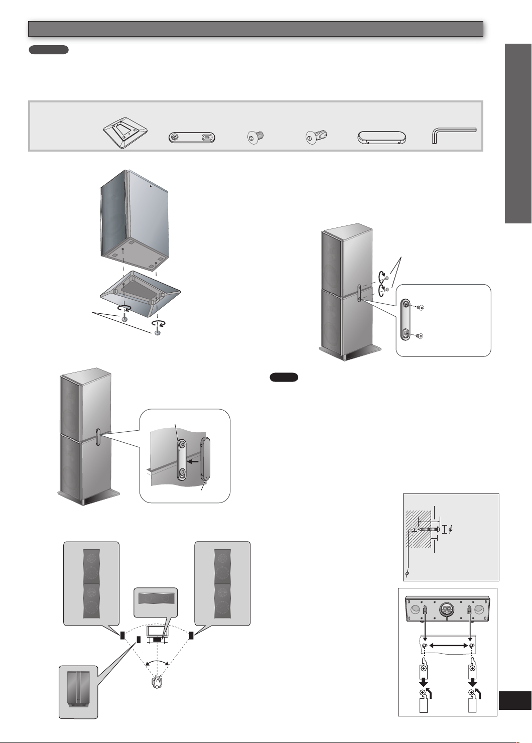
Assemblying the speakers for Bi-Amp TS mode
■
To enjoy better sound quality in Bi-Amp TS mode (➡ Refining the sound quality: Fi Mode, page 34, Operations
Guide), stack the surround speakers on the front speakers.
Supplied
2 Base stands
accessories
6 Metal
brackets
screws
4 Long
screws
6 Side lock
cover
1 Allen key12 Short
Simple setup
Attach the base stands to the front speakers.
1
Front speaker
Base stand
Long screws
Tighten
securely
Push and click the side lock cover to the
4
fastened metal bracket.
Metal bracket
Place the surround speakers on the front
2
speakers.
Fasten the metal bracket with the screws at the
3
right, left and back of the speakers.
Surround
speaker
Front
speaker
Note
If you play 5.1 channel sources in this stack up assembly,
use Bi-Amp TS mode or Party – Stereo mode to enjoy
better sound effect.
Short screws
Tighten
securely
Face the
protruding
portion of
the metal
bracket to the
speakers.
Step 1: Positioning the speakers
Positioning the speakers for Bi-Amp TS mode
■
Surround speaker
front speaker (left)
(left) on top of
Center speaker
Subwoofer
Side lock cover
Surround
speaker (right)
on top of front
speaker (right)
Attaching to a wall
■
You can attach the center
speakers to a wall.
Drive a screw (not
1
included) into the wall.
Fit the hole securely
2
onto the screw(s).
The wall or pillar on which
the speaker is to be attached
should be capable of
supporting 10 kg per screw.
Consult a qualified building
contractor when attaching the
speaker to a wall. Improper
attachment may result in
damage to the wall and
speaker.
Page 4

4
RQTX0072
AM
AN
T
EXTLOOP
FMANT
(75
)
AC IN
EXT
LOL
LOP
+
-
TO
SB-WNC9
SUB-WOOFER
)
(3
TO
SB-PF9
FRONT
)
(3
R L
SPEAKERS
FRONT (R)
FRONT (L)
SUBWOOFER
AC IN
AM
AN
T
EXT
LOOP
FMANT
(75
)
SPEAKERS
+
-
TO
SB-WNC9
SUB-WOOFER
)
(3
TO
SB-PC9
CENTER
)
(3
TO
SB-PF9
FRONT
)
(3
R
L
TO
SB-PS9
SURROUND
)
(3
R
L
SURROUND
Lch
SURROUND
Lch
FRONT
Rch
FRONT
Rch
2
FRONT
Lch
2
FRONT
Lch
CENTER
5
5
CENTER
FRONT (R)
3
3
1
1
6
SUB
WOOFER
SUB
WOOFER
SURROUND
Rch
SURROUND
Rch
4
4
6
SUBWOOFER
SURROUND (R)
SURROUND
(L)
FRONT (L)
CENTER
4
4
DNUORRUS
h
cR
hcR
D
NUORRU
S
4
4
DNUORR
US
hc
R
hcR
DNUORRUS
3
3
hcL
hc
L
D
NU
ORR
US
DNUORRU
S
3
3
hcL
hc
L
DNUORRUS
DNUORRU
S
2
2
hcR
hcR
TNORF
TN
ORF
2
2
h
c
R
h
cR
TNORF
T
NORF
6
6
REFOOW
BU
S
BUS
R
EFOOW
6
6
REFOOW
BUS
BUS
R
EFOOW
1
1
hc
L
hcL
T
NORF
TNORF
1
1
h
c
L
h
cL
T
NORF
TNORF
5
5
RETNEC
RETNE
C
5
5
RETNEC
RETNEC
STEP
SC-NC9
SC-NC9
Simple setup
Supplied
accessories
SC-NC9
Connecting the speakers
Speaker cables
Front (2 x 1.5 m)
•
Subwoofer (1 x 2.5 m)
•
Center (1 x 2 m)
•
Surround (2 x 7 m)
•
Insert the
wire fully.
+: Red
–: Black
1 Speaker cable sticker
Attach the speaker
•
cable stickers to make
connection easier
Speaker cable sticker
Note
Be careful not to cross (short-circuit) or
reverse the polarity of the speaker wires
as doing so may damage the speakers.
Step 2: Connecting the speakers
This unit
SC-NC6
Insert the wire fully.
+: Red
–: Black
+: Red
–: Black
Insert the
wire fully.
This unit
Insert the wire fully.
+: Red
–: Black
+: Red
–: Black
Insert the
wire fully.
Page 5

RQTX0072
5
T
VI
T
REC OUT
A
UX
-
TO
SB-WNC
9
SUB-WOOFE
R
Ω)
(3
TO
SB-PC9
CENTE
R
Ω)
(3
TO
SB-PF9
FRONT
Ω)
(3
S VIDEO
OU
T
AM
ANT
PEAKER
S
EXTLOOP
FMANT
(75
ΩΩ)
FMANT
(75
ΩΩ)
AC IN AC IN
VIDEO OUT
VIDEO IN
Click!
STEP
Television, antenna and AC mains lead connections
AC mains lead Video cableFM indoor
Supplied
AM loop
antenna
antenna
accessories
Connect the AC mains lead after all other connections are complete.
•
Conserving power
The unit consumes a small amount of power (approx. 0.9 W) even when it is in standby mode. To save power
when the unit is not to be used for a long time, unplug it from the household mains socket. You will need to
reset some memory items after plugging in the unit.
AM loop antenna
■
Stand the antenna up on its base.
VIDEO OUT terminal
Place the antenna where reception is the best.
Keep loose antenna cord away from other
wires and cords.
■
Do not connect the unit through
a video cassette recorder,
because the picture may not be
displayed correctly due to copy
FM indoor antenna
■
Affix this end of the antenna
where reception is best.
guard protection.
Turn the television off before
•
connecting, and refer to
the television's operating
Adhesive tape
instructions.
Video cable
(included)
Simple setup
AC mains lead
To household
mains socket
BE SURE TO READ THE CAUTION FOR AC MAINS LEAD ON PAGE 2
OF THE OPERATIONS GUIDE BEFORE CONNECTION.
Insertion of connector
Even when the connector is perfectly inserted,
depending on the type of inlet used, the front
Appliance inlet
Connector
part of the connector may jut out as shown
in the drawing. However there is no problem
using the unit.
Approx. 3.5 mm
Television
While pushing,
insert the wire fully.
Step 3: Television, antenna and AC mains lead connections
Page 6

6
RQTX0072
Other television connections
S VIDEO
OU
T
VIDEO OUT
COMPONENT
VIDEO OUT
Y
P
B
P
R
REC OUT
AUX
R L
A
A
T
7
5
+
AV
AV OUT
-
TO
SB-WNC9
SUB-WOOFE
R
Ω)
(3
TO
B-P9
ENTER
T
)
TO
SB-PF
9
FRON
T
Ω)
(3
TO
SB-PS9
SURROUND
Ω)
(3
AV IN
AV OUT
SC-NC9
-
-
Do not connect the unit through a video cassette recorder, because the picture may not be displayed correctly
•
due to copy guard protection.
Turn the television off before connecting, and refer to the television's operating instructions.
•
Simple setup
Connecting a television with HDMI terminal
■
Note
It is recommended that you use Panasonic’s
•
HDMI-compatible
television
HDMI cable
(not included)
Back of
this unit
Use the HDMI connection to enjoy higher quality audio
and video with a single cable (➡ Glossary, HDMI, page
41, Operations Guide).
Do not use the SCART cable when you use the
•
HDMI cable for the connection.
When HDMI cable is connected, there will be no
•
video output from SCART and component video out
terminal of this unit.
Set “Video Mode” to “On” and “Audio Output” to “On”
•
(➡ “HDMI” tab, page 29, Operations Guide).
Set “Video Output Mode” (➡ Picture Menu, page 24,
•
Operations Guide).
HDMI cable.
[Recommended part number: RP-CDHG15 (1.5
m), RP-CDHG30 (3.0 m), RP-CDHG50 (5.0 m),
etc.]
Non-HDMI-compliant cables cannot be utilized.
•
Using the VIERA Link “HDAVI ControlTM”
If your Panasonic television is an HDMI control
compatible television, you can operate your
television synchronizing with home-theatre
operations or vice versa (➡ Using the VIERA Link
“HDAVI ControlTM”, page 37, Operations Guide).
Make the audio connection (➡ page 38,
•
Operations Guide) when you use “HDAVI
Control” function.
Connecting a television with SCART (AV) terminal
■
Television
Step 3: Television, antenna and AC mains lead connections
Scart cable (not included)
To listen to the sound from the television, select the
•
appropriate audio out (example: Monitor) on the
television.
Sound from the television
Press [EXT-IN] (➡ page 39) to select the “AV” audio
•
input.
To improve picture quality, you can change the video signal output from
the SCART (AV) terminal from “RGB” to either “S-Video” or “Video” to
suit the type of television you are using.
Select “S-Video/YPbPr” or “Video/YPbPr” from QUICK SETUP
•
(➡ page 12, Operations Guide).
Set “Video Mode” to “Off” (➡ HDMI” tab, page 29, Operations Guide).
•
This connection will also enable you to play audio from your television
•
through your stereo system (➡ Using other equipment, page 39,
Operations Guide).
Do not use the HDMI cable when you use the scart cable for the
•
connection.
Back of this
unit
Page 7

RQTX0072
7
S VIDEO
OU
T
V
IDEO OU
T
COMPONENT
VIDEO OUT
Y
P
B
P
R
EC
OUT
AUX
R L
A
T
A
+
AV
AV OUT
S VIDEO
OU
T
S-VIDEO
IN
Using an S VIDEO OUT terminal
VIDEO OUT
COMPONENT
VIDEO OUT
Y
P
B
P
R
COMPONENT
VIDEO IN
PR
PB
Y
■
Television
S Video cable
Back of this unit
(not included)
The S VIDEO terminal achieves a more vivid picture than the VIDEO OUT
terminal by separating the chrominance (C) and luminance (Y) signals. (Actual
results depend on the television.)
Using a COMPONENT VIDEO OUT terminal
■
Television
Back of this unitVideo cable
(not included)
The COMPONENT VIDEO OUT terminals can be used for either interlace
or progressive output and provide a purer picture than the S VIDEO OUT
terminal. Connection using these terminals outputs the colour difference signals
(PB/PR) and luminance signal (Y) separately in order to achieve high fidelity in
reproducing colours.
The description of the component video input terminals depends on the
•
television or monitor (e.g. Y/PB/PR,Y/B- Y/R-Y, Y/CB/CR). Connect to terminals of
the same colour.
Simple setup
Step 4: The remote control
To enjoy progressive video
Connect to a progressive output compatible television.
•
1. Set “Video Mode” to “Off” (➡ “HDMI” tab, page 29, Operations Guide)
2. Set “Video Output Mode” to “480p” or “576p”, and then follow the instructions
on the menu screen (➡ Picture Menu, page 24, Operations Guide).
STEP
The remote control
Do not:
■
Remote control
Insert this
side first when
closing
Insert so the poles (+ and – )
•
match those in the remote control.
Do not use rechargeable type
•
batteries.
Batteries
R6/LR6, AA
Press on the
tab to open
mix old and new batteries.
•
use different types at the same time.
•
heat or expose to flame.
•
take apart or short circuit.
•
attempt to recharge alkaline or manganese batteries.
•
use batteries if the covering has been peeled off.
•
Mishandling of batteries can cause electrolyte leakage which
can severely damage the remote control.
Remove the batteries if the remote control is not going to be
used for a long period of time. Store in a cool, dark place.
Use
■
Aim at the remote control sensor (➡ page 14, Operations
Guide), avoiding obstacles, at a maximum range of 7 m
directly in front of the unit.
Step 3: Television, antenna and AC mains lead connections /
Page 8

DVD/CD
STEP
SC-NC9
SC-NC6
SC-NC9
SC-NC6
SC-NC6
, turn the
^
unit on/off
CLOCK/
TIMER
e, r, w, q
ENTER
QUICK SETUP
Turn on the television and select the appropriate video input on the
television to suit the connection for the unit.
1 2 3
(Press and hold)
,
DVD/CD
q
,
Power ON. Select “DVD/CD”. Display the QUICK
SETUP screen.
4 5 6
Select
/REW ,
u, 2
■
Menu Language
Choose the language for these menus
and the on-screen messages.
TV Type
Select to suit the type of television.
TV Aspect
Choose the setting to suit your
television and preference.
Video Out (AV/Component)
Choose the video signal format to
be output from the SCART (AV) and
Component terminal.
/FF
i, 1
Details of settings
Boxed items are the factory settings in the above diagram.•
RETURN
Confirm
Select the option
from the screen.
English • Français • Español • Deutsch
•
Italiano • Nederlands • Svenska • Polski
•
Standard (Direct View TV)
•
CRT Projector • LCD TV/Projector
•
Projection TV • Plasma TV
•
4:3 : Regular aspect television
•
16:9 : Widescreen television
•
Video/YPbPr : Video and YPbPr
•
S-Video/YPbPr : S-Video and YPbPr
•
RGB/No Output : RGB only
•
Press to finish
QUICK SETUP.
Press to exit.
Matsushita Electric Industrial Co., Ltd.
Web Site: http://panasonic.net
En
RQTX0073-B
H0307VT0
 Loading...