

Operating Instructions
Home Theater Audio System
Model No.
SC-HTX500
.
Dear customer
Thank you for purchasing this product.
For optimum performance and safety, please read these instructions carefully.
Before connecting, operating or adjusting this product, please read the instructions
completely.
Please keep this manual for future reference.
Note
Model number suffix “EB” denotes UK model.
EB
VQT2R75
Caution for AC Mains Lead
Safety precautions
For your safety, please read the following text carefully.
This appliance is supplied with a moulded three pin mains
plug for your safety and convenience.
A 5-ampere fuse is fitted in this plug.
Should the fuse need to be replaced please ensure that
the replacement fuse has a rating of 5-ampere and that it is
approved by ASTA or BSI to BS1362.
Before use
Check for the ASTA mark or the BSI mark on the
body of the fuse.
If the plug contains a removable fuse cover you must
ensure that it is refitted when the fuse is replaced.
If you lose the fuse cover the plug must not be used until a
replacement cover is obtained.
A replacement fuse cover can be purchased from your local dealer.
CAUTION!
IF THE FITTED MOULDED PLUG IS UNSUITABLE FOR THE
SOCKET OUTLET IN YOUR HOME THEN THE FUSE SHOULD BE
REMOVED AND THE PLUG CUT OFF AND DISPOSED OF SAFELY.
THERE IS A DANGER OF SEVERE ELECTRICAL SHOCK IF THE
CUT OFF PLUG IS INSERTED INTO ANY 13-AMPERE SOCKET.
If a new plug is to be fitted please observe the wiring code as stated below.
If in any doubt please consult a qualified electrician.
IMPORTANT
The wires in this mains lead are coloured in accordance
with the following code:
Blue: Neutral, Brown: Live.
As these colours may not correspond with the coloured markings
identifying the terminals in your plug, proceed as follows:
The wire which is coloured Blue must be connected to the terminal
which is marked with the letter N or coloured Black or Blue.
The wire which is coloured Brown must be connected to the terminal
which is marked with the letter L or coloured Brown or Red.
Caution for AC Mains Lead / Safety precautions
WARNING: DO NOT CONNECT EITHER WIRE TO THE EARTH
TERMINAL WHICH IS MARKED WITH THE LETTER E, BY THE
EARTH SYMBOL OR COLOURED GREEN OR GREEN/YELLOW.
THIS PLUG IS NOT WATERPROOF–KEEP DRY.
Before use
Remove the connector cover.
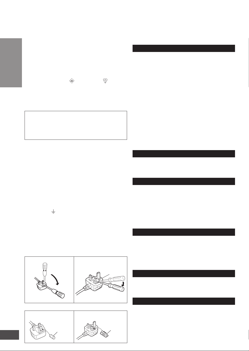
How to replace the fuse
The location of the fuse differ according to the type of AC mains plug
(figures A and B). Confirm the AC mains plug fitted and follow the
instructions below. Illustrations may differ from actual AC mains plug.
1. Open the fuse cover with a screwdriver.
Figure A
2. Replace the fuse and close or attach the fuse cover.
Figure A
2
VQT2R75
Fuse
(5 ampere)
Figure B
Figure B
Fuse cover
Fuse
(5 ampere)
Placement
Set the system up on an even surface away from direct
sunlight, high temperatures, high humidity, and excessive
vibration. These conditions can damage the system and
other components, thereby shorten the system’s service life.
Do not hang from or climb on the system. This may result in
serious injury.
Place the television properly on the system. Use the Fallprevention belt to prevent the television from falling over
and causing serious damage or injury.
Do not place items heavier than the recommended weight
on the system or the shelves.
Be careful not to get hit by the protruded TV.
When you use a stand with a rotating function, install it so it
does not protrude from the top plate of the system and do
not put hands or objects within the rotation range.
When you use a stand with a rotating function, install the system
keeping the distance from the wall so the TV does not hit the wall.
Do not apply oil on the casters (wheels).
Be careful not to catch your fingers when installing the system.
Do not insert your toe into the opening at the bottom of the
system when moving or installing the system.
Voltage
Do not use high voltage power sources. This can overload
the system and cause a fire.
Do not use a DC power source. Check the source carefully when
setting the system up on a ship or other place where DC is used.
AC mains lead protection
Ensure the AC mains lead is connected correctly and not
damaged. Poor connection and lead damage can cause a fire or
electric shock. Do not pull, bend, or place the system on the lead.
Grasp the plug firmly when unplugging the lead. Do not
move the system if AC mains lead is still connected to socket
outlet. Pulling the AC mains lead can cause electric shock.
Do not handle the plug with wet hands. This can cause electric shock.
Remove AC mains plug from socket outlet when not using
for a long period.
Foreign matter
Do not let metal objects fall inside the system. This can
cause electric shock or malfunction.
Do not let liquids get into the system. This can cause electric
shock or malfunction. If this occurs, immediately disconnect
the system from the AC mains lead and contact your dealer.
Do not spray insecticides onto or into the system. They contain
flammable gases which can ignite if sprayed into the system.
Glass shelf
Protect the board from scratching.
Do not touch the board if they crack. Consult your dealer for
immediate replacement.
Do not damage the glass or make an impact on it.
Service
Do not attempt to repair this system by yourself. If sound is
interrupted, indicators fail to light, smoke appears, or any other
problem that is not covered in these instructions occurs, disconnect
the AC mains lead and contact your dealer or an authorized service
centre. Electric shock or damage to the system can occur if the system
is repaired, disassembled or reconstructed by unqualified persons.
Extend operating life by disconnecting the system from the
AC mains if it is not to be used for a long time.
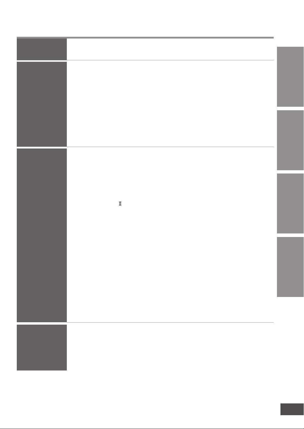
Table of contents
Before use
Connection
Play
Caution for AC Mains Lead ...........2
Safety precautions ........................2
Installing and
assembling the system
Home Theater connections
Basic connections ......................... 11
Connecting equipment with HDMI
terminal (TV, DVD recorder, etc.)
Connecting equipment without HDMI
terminal (DVD player, VCR, etc.) ..........12
Connecting STB, etc. with HDMI
terminal ...................................................13
.. 7
..11
... 12
Enjoying TV, movies
and music ....................14
Enjoying sound field effects ......... 15
Sound effects ................................... 15
Sound mode
Dolby Virtual Speaker ................... 15
Dolby Pro Logic
Cancelling the sound effects ............ 15
Clear Sound Reproduction
from the direction of the TV screen
(CLEAR-MODE DIALOG) ................ 15
You can enjoy dynamic surround effect
even when the sound volume level is low
(WHISPER-MODE SURROUND)
Using the VIERA Link “HDAVI
Control™” ....................................16
Changing this system’s
settings .........................................18
Basic operations ............................ 18
Power saving mode (Eco mode)
“OFF/ON” setting .............................. 19
Adjusting sound quality
(Bass/Treble) .................................... 19
.................................... 15
.......................... 15
......... 15
Supplied accessories ....................4
Control guide .................................5
Checking speaker output ............13
Checking audio output
with a test signal ............................ 13
Checking the subwoofer volume with
the test signal ................................... 13
Adjusting the volume balance of right
and left front speakers ...................... 19
VIERA Link “HDAVI Control” “OFF/ON”
setting
............................................... 19
Fixing the TV audio input to the
optical digital input ............................ 19
Switching the input automatically to
STB, etc. .......................................... 20
Setting when images arrive later than
audio ................................................ 20
Switching between dual sounds ....... 20
Clear audio at low volume ................ 20
Setting when the beginning of a CD
track is cut ........................................ 20
Factory settings (Reset) ................... 21
To prevent other Panasonic
equipment from operating with this
system’s remote control ................... 21
Convenient functions ..................21
Muting ............................................. 21
Displaying current status .............. 21
Before useConnectionPlay
and other
information
Troubleshooting
Specifications ..............................22
Troubleshooting
and other
information
Digital audio signals supported
by this system
Maintenance .................................23
Troubleshooting guide ................24
....................................
23
Error messages ...........................26
3
VQT2R75
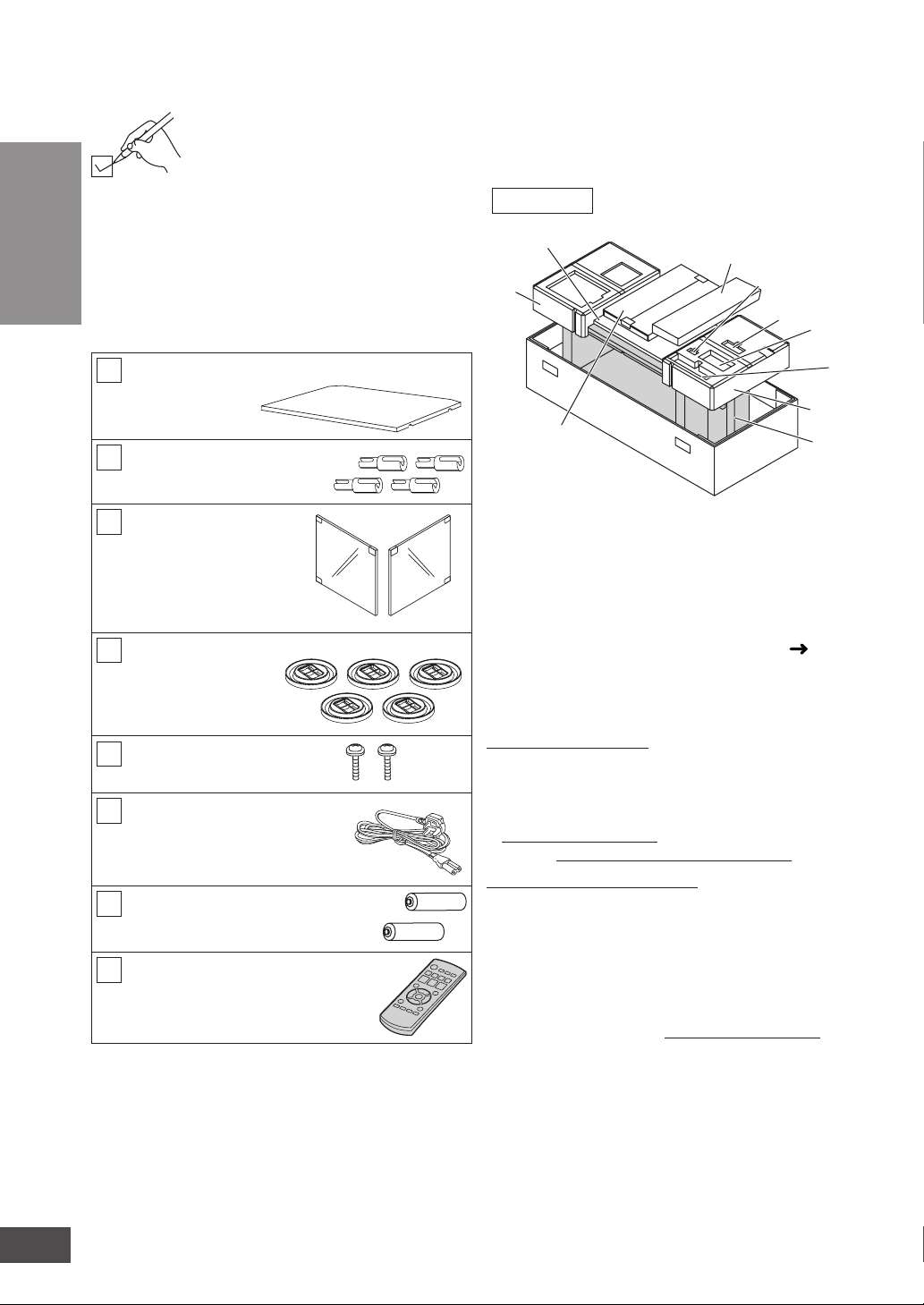
Supplied accessories
Please check and identify the supplied accessories.
Use numbers indicated in parentheses when asking
for replacement parts.
(Product numbers correct as of January 2010. These
may be subject to change.)
Before use
Keep the screws and the shelf holders out of reach of
children to prevent swallowing.
1 Shelf
[RFA3072]
4 Shelf holders
[RMRX0095-H]
Supplied accessories
2 Glass doors
(1 for right and 1 for left)
Left side [RXQ1809]
Right side [RXQ1857]
Left side Right side
5 Caster trays
[TBLB3008]
2 Screws
[XTW4+16JFJK]
1 AC mains lead
[K2CZ3YY00005]
2 Batteries
(R6, AA)
1 Remote control
[N2QAYB000527]
Packing plan
7
6✽1
8
1System 2AC mains lead
3Caster trays, Screws, Shelf holders
4Remote control 5Batteries
6Cushion
7Shelf
8Glass door
•
Use 6✽1 and 6✽2 to remove casters. (
6
5
4
3
2
6✽2
1
page
7)
Sales and Support Information
Customer Care Centre
• For customers within the UK: 0844 844 3852
• For customers within the Republic of Ireland:
01 289 8333
• Visit our website for product information
www.panasonic.co.uk
• E-mail: customer.care@panasonic.co.uk
Direct Sales at Panasonic UK
• For customers: 0844 844 3856
Order accessory and consumable items for your product
•
with ease and confidence by phoning our Customer
Care Centre
Monday-Thursday 9:00am-5:30pm,
Friday 9:30am-5:30pm (Excluding public holidays).
• Or go on line through our Internet Accessory
ordering application at www.pas-europe.com.
• Most major credit and debit cards accepted.
• All enquiries transactions and distribution facilities
are provided directly by Panasonic UK Ltd.
• It couldn’t be simpler!
• Also available through our Internet is direct
shopping for a wide range of finished products,
take a browse on our website for further details.
4
VQT2R75
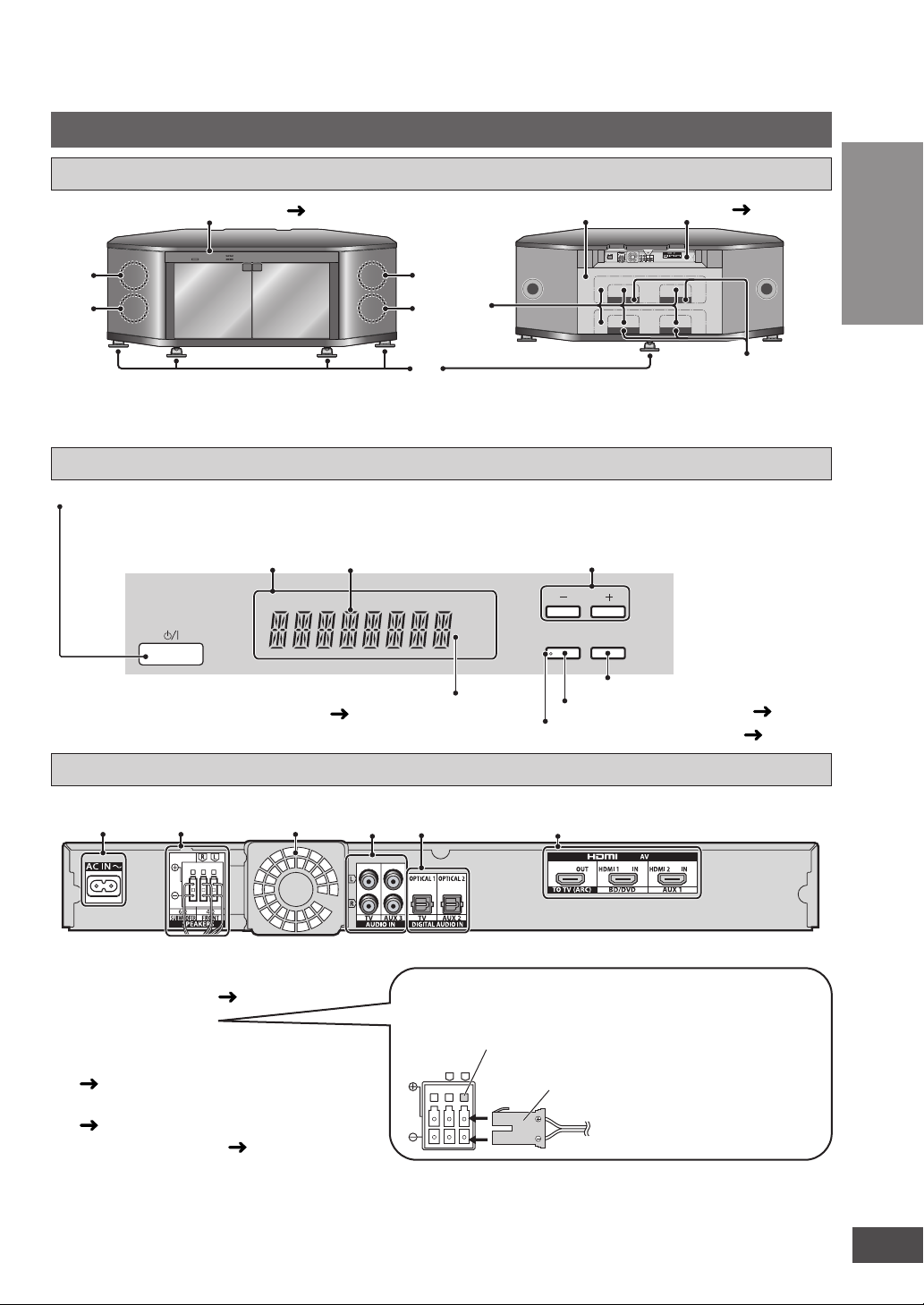
Control guide
This system
Front view/Rear view
Front view Rear view
Control panel (
1
3
below)
2
3
6
4
5
Amplifi er ( below)
OPTICAL1OPTICAL2
7
1Front speaker (left) 2Front speaker (right) 3Subwoofer 4Caster/Caster trays 5Rear panel
6Cut-outs 7Openings
Control panel
Standby/on switch (8)
Press to switch the unit from on to standby mode or vice versa. In standby mode, the unit
is still consuming a small amount of power.
Display
General display
When the surround digital signal is being input or
the sound effects are being used
( page 15)
SRD
Lights on when using “CLEAR-MODE DIALOG” ( page 15)
For adjusting volume
VOLUME
DIALOG
INPUT
SELECTOR
CLEAR-MODE
“INPUT SELECTOR” switch
For using “CLEAR-MODE DIALOG” ( page 15)
Before use
Control guide
Amplifi er
12 345 6
1AC input terminal ( page 11)
2Speaker terminals
3Exhaust hole (Cooling fan)
4AUDIO IN terminals (Analogue)
(
pages 11, 12)
5DIGITAL AUDIO IN terminals
(
pages 12, 13)
6 HDMI AV terminals (
page 12)
Speaker terminals
If the connectors become disconnected, refer to the
illustration below for connection.
Terminal
block
L
R
Connector
The connectors and terminals
are colour-coded and can only
be inserted in one direction.
Insert each connector into the
terminal of the same colour until
it clicks in position.
5
VQT2R75

Control guide
Remote control (This manual explains the operations mainly using the remote control.)
Standby/on button (
Test signal output (
Before use
For using “CLEAR-MODE
DIALOG” (
For using “WHISPER-MODE
SURROUND” (
For displaying the current status/
Control guide
Entering setup mode
(
pages 18 to 21)
For selecting or cancelling Dolby
Virtual Speaker, Dolby Pro Logic and
sound mode (
page 15)
page 14)
page 13)
page 15)
page 15)
Inserting the batteries
Press on the tab to open.
(R6/LR6, AA)
Insert so the poles (( and ))
match those in the remote control.
Use manganese batteries or
alkaline batteries.
Input selector (page 14)
For adjusting speaker output
( page 13)
For adjusting the volume
(
pages 13, 14)
Muting (
page 21)
Making adjustment and settings/
confirming settings
(
pages 18 to 21)
For returning to the previous menu
(
page 18)
• Do not mix old and new batteries.
• Do not use different types of batteries at the same time.
• Do not take apart or short circuit.
• Do not attempt to recharge alkaline or manganese batteries.
• Do not use batteries if the covering has been peeled off.
• Do not heat or expose to flame.
•
Do not leave the batteries in an automobile exposed to direct
sunlight for a long period of time with doors and windows closed.
Mishandling of batteries can cause electrolyte leakage which can
severely damage the remote control.
Remove the batteries if the remote control is not going to be
used for a long period of time. Store them in a cool, dark place.
6
VQT2R75
CAUTION
Danger of explosion if battery is incorrectly replaced. Replace only with the same or equivalent type
recommended by the manufacturer. Dispose of used batteries according to the manufacturer’s instructions.
Using the remote control
Control panel
Within 7 meters at the
front (The remote
controlling range varies
according to the angles.)
The distance and the angles
are approximate.
Remote control
signal sensor
Transmission
window
CLEAR-MODE
DIALOG
VOLUME
INPUT
SELECTOR
30°30°
Note
• Do not place an object between the signal sensor and the remote
control.
• Do not expose the signal sensor to the direct sunlight or the strong light
of a fluorescent lamp.
• Keep the transmission window and the system’s sensor free from dust.
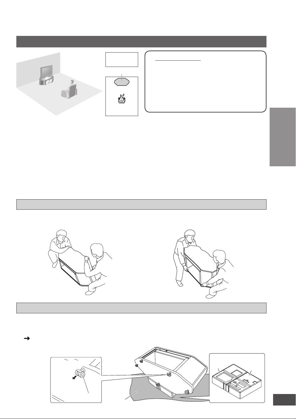
Installing and assembling the system
cloth, etc
Installation
Setup
example
This system
• Take adequate measures to prevent the TV from
falling down. Make sure to set the caster trays
when the casters are attached.
• You can install this system so that it is flush with
the wall at the back. (Depending on the depth of
equipment to install or the type of cable, installing
this system flush with the wall may be impossible.)
• Do not place in front of curtains as they may
obstruct the system’s exhaust hole.
• If the surface of the wooden floor is soft, the caster
mark may remain.
How to lift the system
1 Tilt the system forward slightly then place your
hand under the bottom of the back side.
• At least 2 people are necessary for
lifting up the system.
• Use a phillips-head screwdriver.
(Do not use an electric screwdriver.)
• Avoid unstable places. Choose a flat
location for installation.
• Handle the glass doors with enough
care.
• Do not put anything but a TV on the top board of
this system.
Do not put the following things in particular.
x Putting a hot thing may leave the mark and it
may not come off.
x If you put a vase with water in it and when it falls
down, the water may splash over this system
and this can cause malfunction.
2 Place your other hand under the bottom of the
front side and lift the system up keeping it
horizontal.
Connection
Back side
Front side
Removing casters
• Remove the casters on soft floor materials
(i.e. thick-piled carpet, etc.).
• To remove the casters, place the cushions
(
indicated with 6✽1 and 6✽2 on page 4,
packing plan) used at both ends of packaging, and
place this system with its back side facing down on
them.
(Bottom plate)
Hold and pull
Caster
Soft
• Do not put anything on and in the system when
removing casters. (You do not need to remove the
amplifier and speakers as they are fixed.)
Front side
Cushion
6✽1
6✽
Installing and assembling the system
2
7
VQT2R75
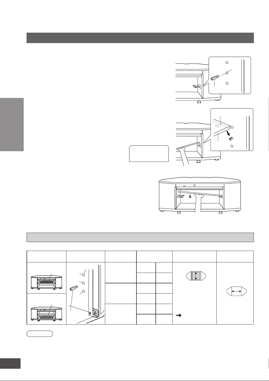
Installing and assembling the system
Shelf assembly
Remove the tape fixing the glass holder and open the glass holder.
Insert 2 shelf holders (supplied) into
1
the dowel holes on one side.
Insert the shelf (supplied) with a
2
slope and set it adjusting the shelf
groove on the shelf holders.
• When inserting the shelf, tilt upward the side
of shelf where the shelf holders have been
Connection
3
inserted.
(Shelf)
Holding the shelf, insert 2 shelf
holders into the dowel holes on the
other side as well. Set the shelf
horizontally.
• The height of the shelf can be adjusted at 3
different levels (high, middle, low).
• Change the positions of holes for the shelf
holder to adjust the height of shelf.
• When you do not install the shelf, keep the
shelf holders in a safe place.
Back
Front
Dowel hole
Shelf holder
Groove (Under the shelf)
Shelf
About equipment stored on the shelf
Installing and assembling the system
Dowel hole
position
Dowel hole
High
Middle
Low
Shelf
holder
8
VQT2R75
Setting position
Upper shelf A
Lower shelf B
Note
• Do not put equipment weighing more than 12 kg on the upper shelf A and lower shelf B.
• Refer to pages 11 to 13 for connections with other equipment.
• Image interference may occur if you put recording equipment on the shelf (Upper shelf A). Put it on the base board
(Lower shelf B) if this occurs.
• Depending on the equipment to install, the cables may not be connected. To install the equipment, adjust the height of the shelf
to the position where the cables can come out from the cut-outs.
Shelf holder
position
High
Middle
Low
Height of
compartment
A
B
A
B
A
B
95
147
125
117
155
87
Maximum depth for
storing equipment
(Upper view)
If the depth of
equipment to install
is 280 mm or more,
remove the cut-out
(large window).
(
340
page 9)
unit (mm)
Width of
compartment
580
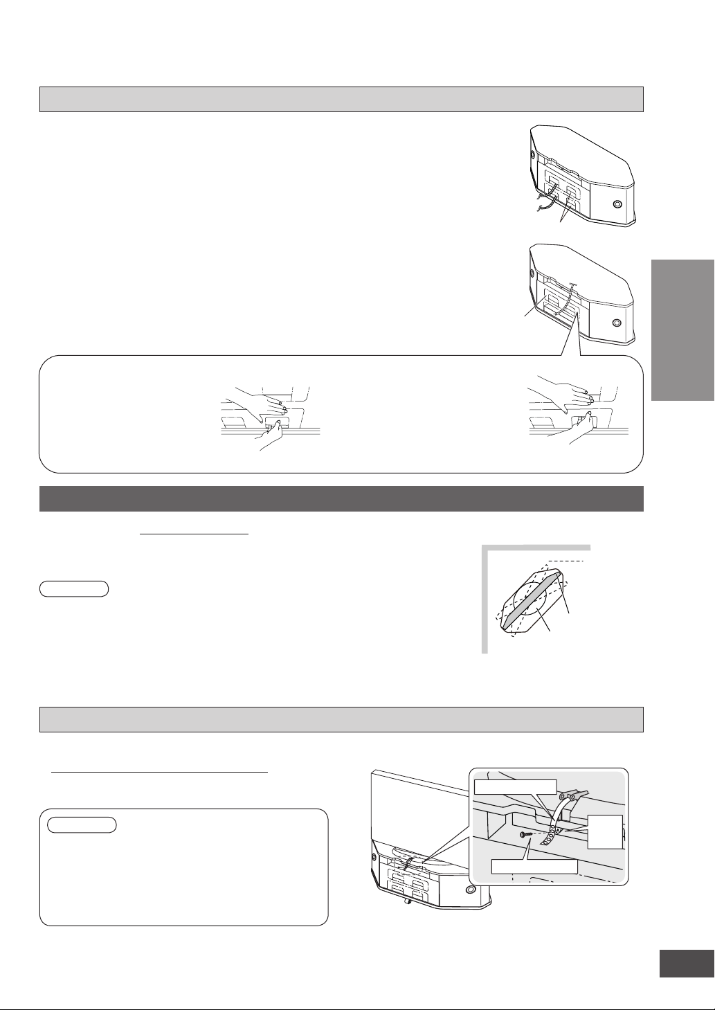
Taking out cables (Refer to the operating instructions of equipment as well.)
After installing equipment in the system, pull out
(Rear view)
the cables from the openings of the rear panel.
In the following cases, remove the cut-outs. This will
Openings
strain the connection parts and may cause malfunction.
• When the cables are too thick to pull out
Remove the small windows.
• When the depth of equipment to install is 280 mm or more
Remove the large windows.
To remove the small window
Insert your hand into the
opening as illustrated, press
the center of small window
with your thumb and pull out
To remove the large window
After removing the small window,
insert your hand as illustrated,
press along the dotted line with
your thumb and
pull out the panel.
Cut-outs
the panel.
• Hold the rear panel with the other hand so it does not bend while removing.
Installing the television (Please also refer to the television’s operating instructions.)
Recommended : 42V inches or less
Place the TV stand in the center of the top board of the system.
Note
• Do not put equipment weighing more than 80 kg on the top board.
• Lift the television when placing it on the system. Dragging it may damage the top board.
(For details, refer to the television’s operating instructions.)
• When you use a stand with a rotating function, keep distance away from the wall so the TV
does not hit the wall.
• This system is not magnetically shielded. Do not use with a CRT-based television.
(Upper view of the setup)
Wall
Arrange the
stand so the
TV does not
hit the wall
when rotated.
TV
Stand
Connection
Installing and assembling the system
Fall-prevention measure for TV
Fixing to the system
• Make sure to use the supplied screw to attach
the fall-prevention belt (supplied with a TV) as
illustrated at right.
Note
• If the fall-prevention belt is not supplied with the TV,
consult with your supplying dealer for advice.
• Do not over-tighten the screws to avoid damaging the
fixing holes.
• For attaching the fall-prevention belt to the TV, follow the
operating instructions for the TV.
(Setup example)
Fall-prevention belt
Prepared
screw
hole
Screw (supplied)
The illustration is an example.
The shape may differ from the actual product.
9
VQT2R75
 Loading...