

Panasonic S*C09*3E8, S*C12*9E8, S*C16*9E8 Installation Manual
ENGLISH ................ 1
ESPAÑOL ............. 32
ITALIANO ..............63
Installation Manual
AIR-TO-WATER HEATPUMP INDOOR UNIT
S*C09*3E8, S*C12*9E8, S*C16*9E8
Required tools for Installation Works
1 Phillips screw driver
2 Level gauge
3 Electric drill
4 Spanner
5 Pipe cutter
6 Reamer
7 Knife
8 Gas leak detector
9 Measuring tape
10 Megameter
11 Multimeter
12 Torque wrench
SAFETY PRECAUTIONS
Read the following “SAFETY PRECAUTIONS” carefully before installation.
•
Electrical work must be installed by a licensed electrician. Be sure to use the correct rating and main circuit for the model to be installed.
•
The caution items stated here must be followed because these important contents are related to safety. The meaning of each indication
•
used is as below. Incorrect installation due to ignoring of the instruction will cause harm or damage, and the seriousness is classifi ed by the
following indications.
Please leave this installation manual with the unit after installation.
•
WARNING
CAUTION
The items to be followed are classifi ed by the symbols:
Carry out test run to confi rm that no abnormality occurs after the installation. Then, explain to user the operation, care and maintenance as
•
stated in instructions. Please remind the customer to keep the operating instructions for future reference.
This indication shows the possibility of causing death or serious injury.
This indication shows the possibility of causing injury or damage to properties only.
Symbol with white background denotes item that is PROHIBITED from doing.
Symbol with dark background denotes item that must be carried out.
42 N•m (4.2 kgf•m)
65 N•m (6.5 kgf•m)
ENGLISH
WARNING
Do not use unspecifi ed cord, modifi ed cord, joint cord or extension cord for power supply cord. Do not share the single outlet with other electrical
appliances. Poor contact, poor insulation or over current will cause electrical shock or fi re.
Do not tie up the power supply cord into a bundle by band. Abnormal temperature rise on power supply cord may happen.
Keep plastic bag (packaging material) away from small children, it may cause suffocation.
Do not use pipe wrench to install refrigerant piping. It might deform the piping and cause the unit to malfunction.
Do not purchase unauthorized electrical parts for installation, service, maintenance and etc.. They might cause electrical shock or fi re.
Do not modify the wiring of Indoor Unit for installation of other components (i.e. heater, etc). Overloaded wiring or wire connection points may
cause electrical shock or fi re.
Do not add or replace refrigerant other than specifi ed type. It may cause product damage, burst and injury etc.
Do not use joint cable for Indoor / Outdoor Unit connection cable. Use specifi ed Indoor / Outdoor Unit connection cable, refer to instruction 6
CONNECT THE CABLE TO THE INDOOR UNIT and connect tightly for Indoor / Outdoor Unit connection. Clamp the cable so that no external
force will be acted on the terminal. If connection or fi xing is not perfect, it will cause heat up or fi re at the connection.
For electrical work, follow local wiring standard, regulation and this installation instruction. An independent circuit and single outlet must be used.
If electrical circuit capacity is not enough or defect found in electrical work, it will cause electrical shock or fi re.
For water circuit installation work, follow to relevant European and national regulations (including EN61770) and local plumbing and building
regulation codes.
Engage dealer or specialist for installation. If installation done by the user is defective, it will cause water leakage, electrical shock or fi re.
This is a R410A model, when connecting the piping, do not use any existing (R22) pipes and fl are nuts. Using such same may cause abnormally
•
high pressure in the refrigeration cycle (piping), and possibly result in explosion and injury. Use only R410A refrigerant.
Thickness for copper pipes used with R410A must be 0.8mm or more. Never use copper pipes thinner than 0.8mm.
•
It is desirable that the amount of residual oil is less than 40mg/10m.
•
When install or relocate Indoor Unit, do not let any substance other than the specifi ed refrigerant, e.g. air etc. mix into refrigerant cycle (piping).
Mixing of air etc. will cause abnormal high pressure in refrigeration cycle and result in explosion, injury etc.
ACXF60-03130
1
4
1
Install according to this installation instructions strictly. If installation is defective, it will cause water leakage, electrical shock or fi re.
Install at a strong and fi rm location which is able to withstand the set’s weight. If the strength is not enough or installation is not properly done, the
set will drop and cause injury.
ENGLISH
This equipment is strongly recommended to be installed with Residual Current Device (RCD) on-site according to the respective national wiring
rules or country–specifi c safety measures in terms of residual current.
During installation, install the refrigerant piping properly before run the compressor. Operation of compressor without fi xing refrigeration piping and
valves at opened condition will cause suck-in of air, abnormal high pressure in refrigeration cycle and result in explosion, injury etc.
During pump down operation, stop the compressor before remove the refrigeration piping. Removal of refrigerant piping while compressor is
operating and valves are opened will cause suck-in of air, abnormal high pressure in refrigerant cycle and result in explosion, injury etc.
Tighten the fl are nut with torque wrench according to specifi ed method. If the fl are nut is over tightened, after a long period, the fl are may break
and cause refrigerant gas leakage.
After completion of installation, confi rm there is no leakage of refrigerant gas. It may generate toxic gas when the refrigerant contacts with fi re.
Ventilate the room if there is refrigerant gas leakage during operation. Extinguish all fi re sources if present. It may cause toxic gas when the
refrigerant contacts with fi re.
Only use the supplied or specifi ed installation parts, else, it may cause unit vibrate loose, water leakage, electrical shock or fi re.
The unit is only for use in closed water system. Utilization in an open water circuit may lead to excessive corrosion of water piping and risk of
incubating bacteria colonies, particularly Legionella, in water.
If there is any doubt about the installation procedure or operation, always contact the authorized dealer for advice and information.
Select a location where in case of water leakage, the leakage will not cause damage to other properties.
When installing electrical equipment at wooden building of metal lath or wire lath, in accordance with electrical facility standard, no electrical
contact between equipment and building is allowed. Insulator must be installed in between.
Any work carried out on the Indoor Unit after removing any panels which is secured by screws, must be carried out under the supervision of
authorized dealer and licensed installation contractor.
This unit must be properly earthed. The electrical earth must not be connected to a gas pipe, water pipe, the earth of lightening rod or a telephone.
Otherwise there is a danger of electrical shock in the event of an insulation breakdown or electrical earth fault in the outdoor unit.
Do not install the Indoor Unit at place where leakage of fl ammable gas may occur. In case gas leaks and accumulates at surrounding of the
unit, it may cause fi re.
Do not release refrigerant during piping work for installation, re-installation and during repairing a refrigeration parts. Take care of the liquid
refrigerant, it may cause frostbite.
Do not install this appliance in a laundry room or other high humidity location. This condition will cause rust and damage to the unit.
CAUTION
Make sure the insulation of power supply cord does not contact hot part (i.e. refrigerant piping) to prevent from insulation failure (melt).
Do not apply excessive force to water pipes that may damage the pipes. If water leakage occurs, it will cause fl ooding and damage to other
properties.
Select an installation location which is easy for maintenance.
Carry out drainage piping as mentioned in installation instructions. If drainage is not perfect, water may enter the room and damage the furniture.
Power supply connection to Indoor Unit.
Power supply point should be in easily accessible place for power disconnection in case of emergency.
•
Must follow local national wiring standard, regulation and this installation instruction.
•
Strongly recommended to make permanent connection to a circuit breaker.
•
- Power Supply 1: Use approved 20A 4-poles circuit breaker with a minimum contact gap of 3.0mm.
- Power Supply 2: Use approved 15/16A 2-poles circuit breaker with a minimum contact gap of 3.0mm. (Only applicable for S*C09*3E8)
Use approved 20A 4-poles circuit breaker with a minimum contact gap of 3.0mm. (Only applicable for S*C12*9E8/S*C16*9E8)
Ensure the correct polarity is maintained throughout all wiring. Otherwise, it will cause electrical shock or fi re.
After installation, check the water leakage condition in connection area during test run. If leakage occurs, it will cause damage to other properties.
Installation work.
It may need two or more people to carry out the installation work. The weight of Indoor Unit might cause injury if carried by one person.
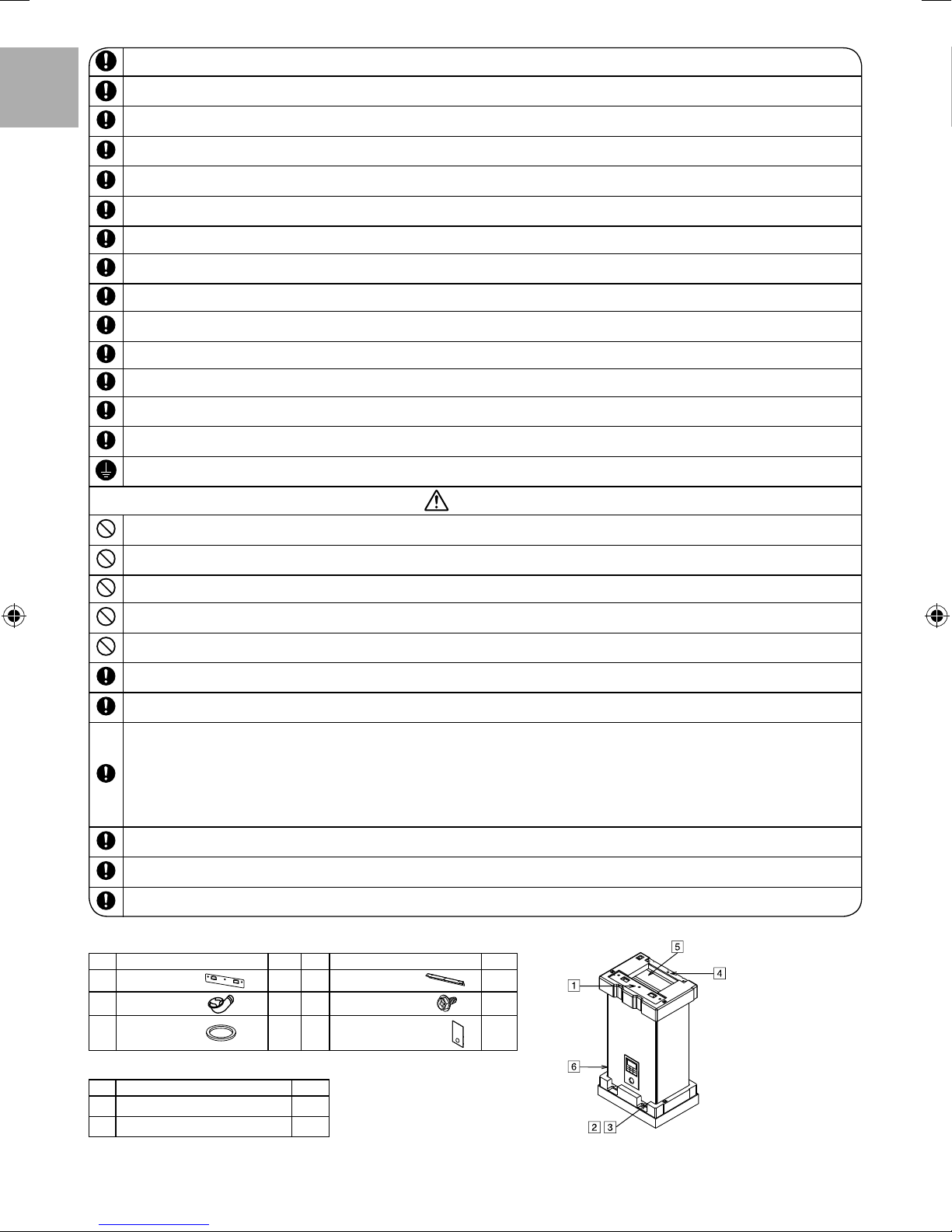
Attached Accessories
No. Accessories part Qty. No. Accessories part Qty.
Installation plate
1
Drain elbow
2
Packing
3
1
1
1
Installation plate
4
Screw
5
Remote Controller Cover
6
or
1
3
1
Optional Accessories
No. Accessories part Qty.
Optional PCB (CZ-NS4P)
7
Network Adaptor (CZ-TAW1)
8
2
1
1
Field Supply Accessories
No. Part Model Specifi cation Maker
2-way valve kit
i
*Cooling model
3-way valve kit
ii
iii
Room thermostat
iv Mixing valve - 167032 AC230V Caleffi
v
Pump
vi Buffer tank sensor - PAW-A2W-TSBU - -
vii
Outdoor sensor
viii
Zone water sensor
ix
Zone room sensor
x
Solar sensor
It is recommended to purchase the fi eld supply accessories listed in above table.
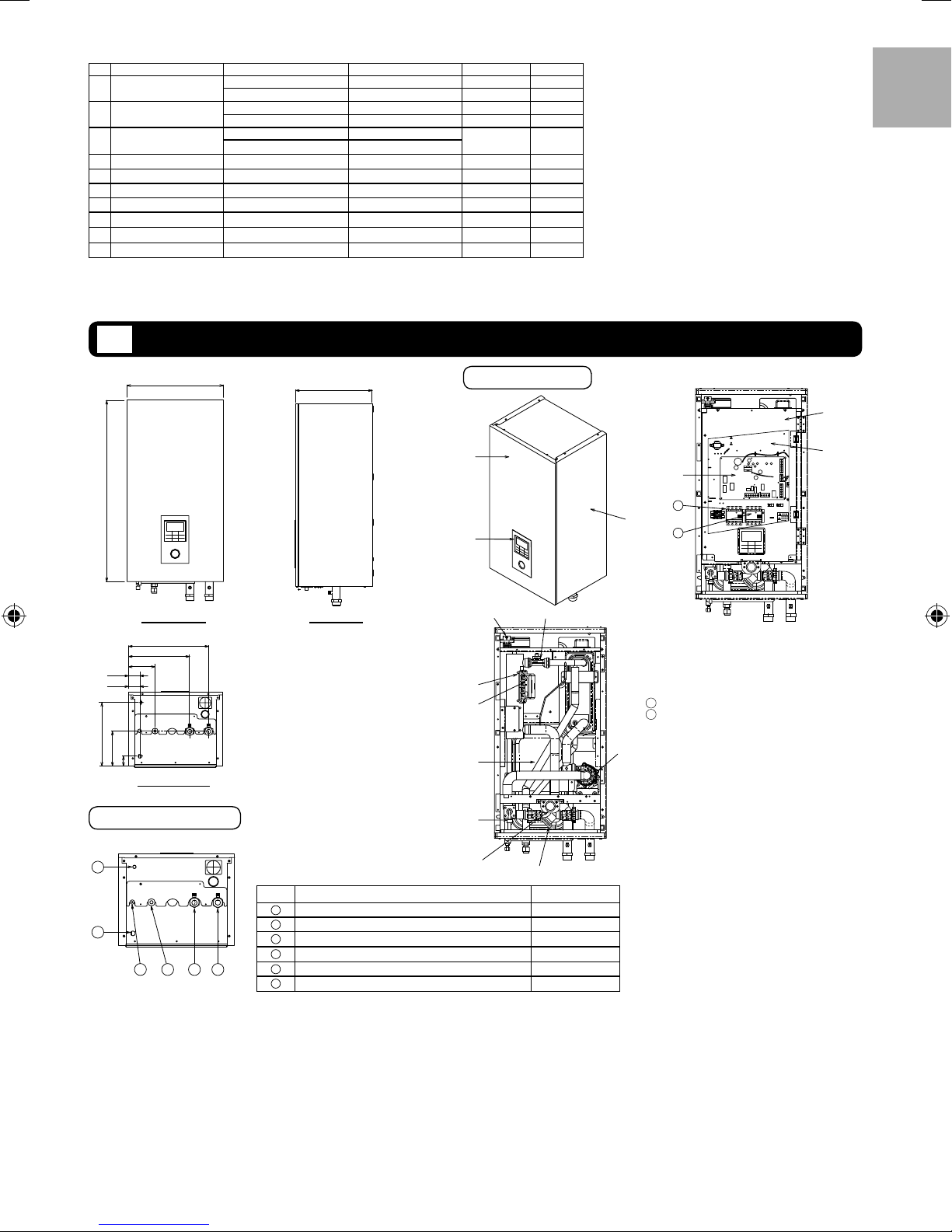
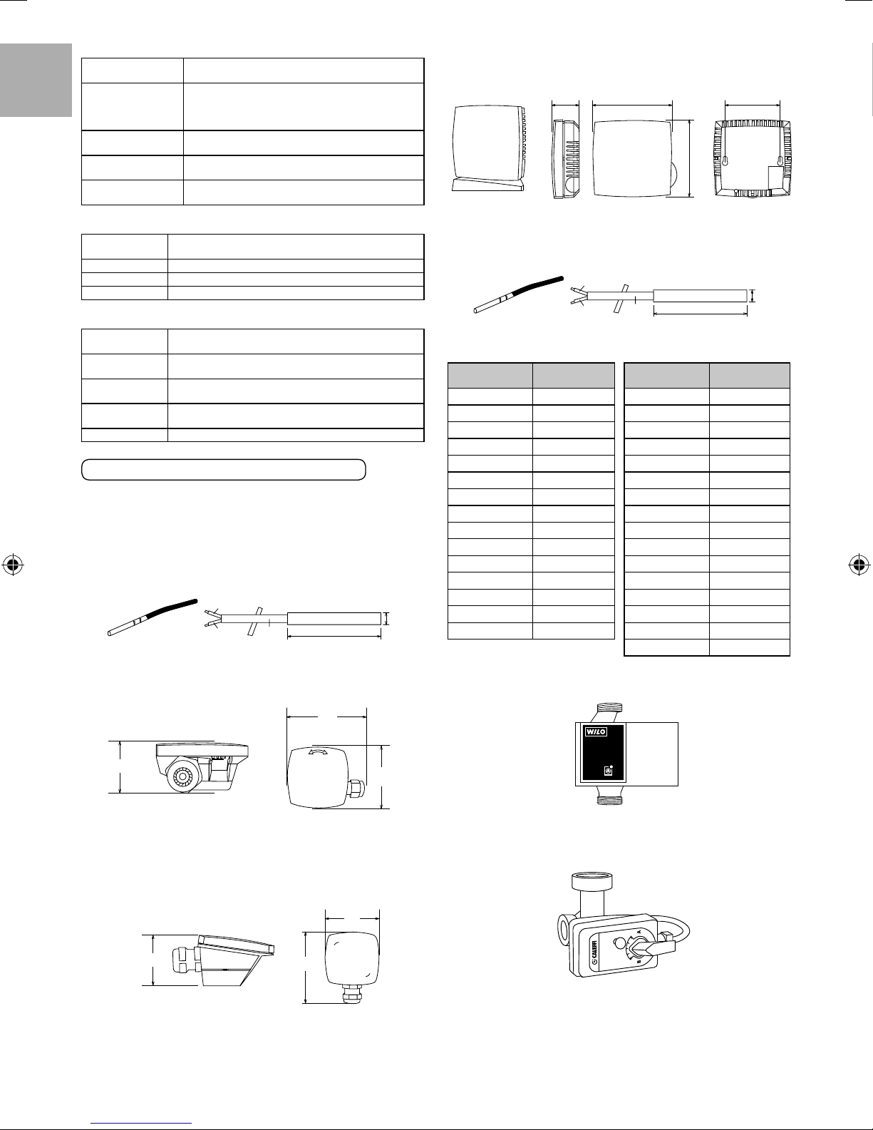
DIMENSION DIAGRAM
1
Electromotoric Actuator SFA21/18 AC230V Siemens
2-port Valve VVI46/25 - Siemens
Electromotoric Actuator SFA21/18 AC230V Siemens
3-port Valve VVI46/25 - Siemens
Wired PAW-A2W-RTWIRED
Wireless PAW-A2W-RTWIRELESS
- Yonos 25/6 AC230V Wilo
- PAW-A2W-TSOD - -
- PAW-A2W-TSHC - -
- PAW-A2W-TSRT - -
- PAW-A2W-TSSO - -
AC230V -
ENGLISH
500
892
FRONT VIEW
427
326.5
141.5
62
58.5
285
153
53
BOTTOM VIEW
Pipe Position Diagram
f
e
a b c d
340
SIDE VIEW
Letter Pipe Description Connection Size
a
Refrigerant liquid 5/8-18UNF
b
Refrigerant gas 7/8-14UNF
c
Water outlet
d
Water inlet
e
Drain water hole -
f
Pressure relief valve drainage
Main Components
1
3
9
0
a
b
c
d
8
e
R 1¼"
R 1¼"
3/8"
4
5-1
2
f
5-2
Cabinet front plate
1
Cabinet side plate (2 pieces)
2
Remote controller
3
PCB
4
3 Phase RCCB/ELCB (Main Power)
5-1
Single Phase RCCB/ELCB (Booster Heater)
5-2
for S*C09*3E8
3 Phase RCCB/ELCB for S*C12*9E8,
S*C16*9E8
Control board cover
6
Control board
7
Flow sensor
8
Air purge valve
9
Backup heater
0
Overload protector (4 pieces)
a
Expansion vessel
b
Pressure relief valve
c
Water pressure gauge
d
Water fi lter
e
Water pump
f
6
7
3
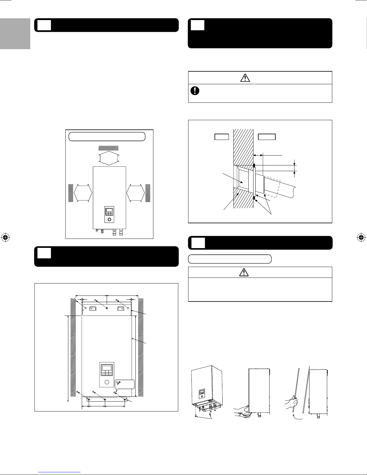
SELECT THE BEST LOCATION
2
There should not be any heat source or steam near the unit.
A place where air circulation in the room is good.
ENGLISH
A place where drainage can be easily done.
A place where noice prevention is taken into consideration.
Do not install the unit near the door way.
Ensure the spaces indicated by arrows from the wall, ceiling,
fence or other obstacles.
Recommended installation height for indoor unit shall be at least
800 mm.
Must install on a vertical wall.
When install electrical equipment at wooden building of metal
lath or wire lath, according to electrical facility technical standard,
no electrical contact between equipment and building is allowed.
Insulator must be installed in between.
Do not install the unit at outdoor. This is designed for indoor
installation only.
TO DRILL A HOLE IN THE
4
WALL AND INSTALL A
SLEEVE OF PIPING
1. Insert the piping sleeve to the hole.
2. Fix the bushing to the sleeve.
3. Cut the sleeve until it extrudes about 15 mm from the wall.
CAUTION
When the wall is hollow, please be sure to use the sleeve
for tube assembly to prevent dangers caused by mice biting
the connection cable.
4. Finish by sealing the sleeve with putty or caulking compound at
the fi nal stage.
Wall
Required space for installation
100 mm
or more
100 mm
or more
HOW TO FIX INSTALLATION
3
100 mm
or more
PLATE
The mounting wall is strong and solid enough to prevent it from
More than 375 More than 375
≥1556 from
ground
vibration
(Unit in mm)
WallWall
55
Installation
plate
1
Indoor Unit
body
756
Indoor Outdoor
15 mm
Sleeve for tube
assembly
Approx. 5 - 7 mm
Bushing for tube assembly
ø70 mm through hole
INDOOR UNIT INSTALLATION
5
Putty or caulking compound
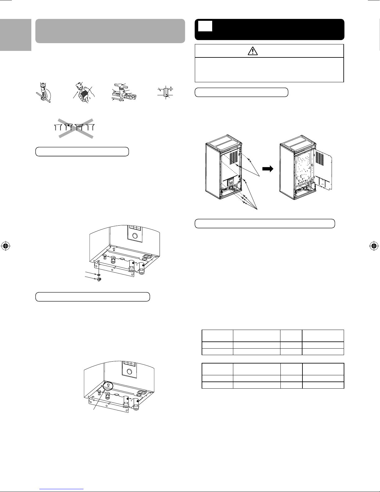
Access to Internal Components
WARNING
This section is for authorized and licensed electrician/water
system installer only. Work behind the front plate secured by
screws must only be carried out under supervision of qualifi ed
contractor, installation engineer or service person.
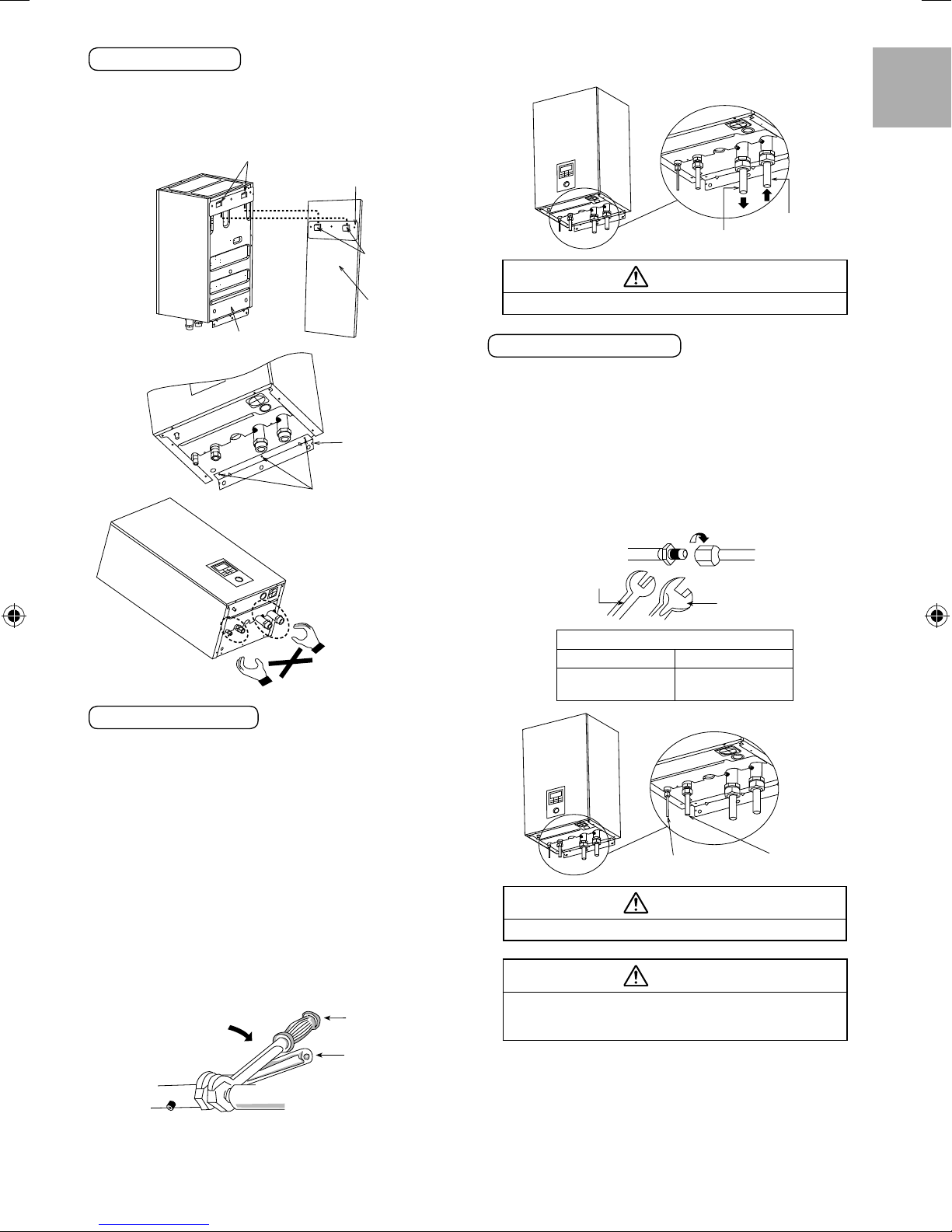
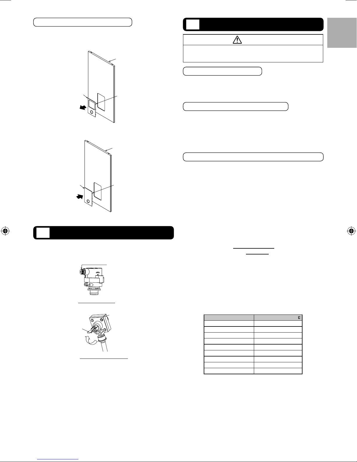
Please follow the steps below for take out front plate. Before
removing the front plate of indoor unit, always switch off all power
supply (i.e. indoor unit power supply, heater power supply and Tank
Unit power supply).
1. Remove the 2 mounting screws which located at bottom of the
front plate.
2. Gently pull the lower section of the front plate towards you to
remove the front plate from left and right hooks.
3. Hold the left edge and right edge of front plate to lift up front
plate from hooks.
Hook
Bolt size M8
200
16070
The centre of installation plate should be at more than 375 mm at
right and left of the wall.
The distance from installation plate edge to ground should more
than 1556 mm.
Always mount the installation plate horizontally plate by aligning the
•
marking thread and using a level gauge.
Mount the installation plate on the wall with 6 sets of plug, bolt and
•
washer (all non-supply) with size M8.
4
Installation
plate
4
Screws
Lift up
Install the indoor unit
1. Engage the slots on the indoor unit to the hooks of installation
plate 1. Ensure the hooks are properly seated on the installation
plate by moving it left and right.
2.
Fix the screws 5 to the holes on the hooks of installation plate 4,
as illustrated below.
Slots
Installation plate
1
Hooks
Wall
After installation, check the water leakage condition in connection
•
area during test run.
Water Inlet
Water Outlet
CAUTION
Do not over tighten, over tightening cause water leakage.
ENGLISH
Indoor unit back
Installation plate
Screws
5
Note: Do not lift the
Indoor Unit by holding the
refrigerant and water pipes
to prevent damage of the
pipes.
4
Water piping installation
The minimum requirement of water in the system is 50 litres. If
•
this value could not be achieved, please install additional buffer
tank (fi eld supply).
Water inlet and water outlet in indoor unit are used for connection
•
to water circuit. Please request a licensed technician to install this
water circuit.
This water circuit must comply with all relevant European and
•
national regulations, i.e. IEC/EN 61770.
Be careful not to deform the piping to excessive force when doing
•
piping connection job.
Use Rp 1¼" nut for both water inlet and outlet connection and
•
clean all pipings with tap water before connecting to the indoor unit.
Cover the pipe end to prevent dirt and dust when inserting it
•
through a wall.
Choose proper sealer which can withstand the pressures and
•
temperatures of the system.
If an existing tank is to be connected to this indoor unit, ensure the
•
pipes are clean before water pipe installation is carried out.
Be sure to use two spanners to tighten the connection. Tighten the
•
nuts with torque wrench: 117.6N•m.
Torque wrench
Spanner
Indoor unit
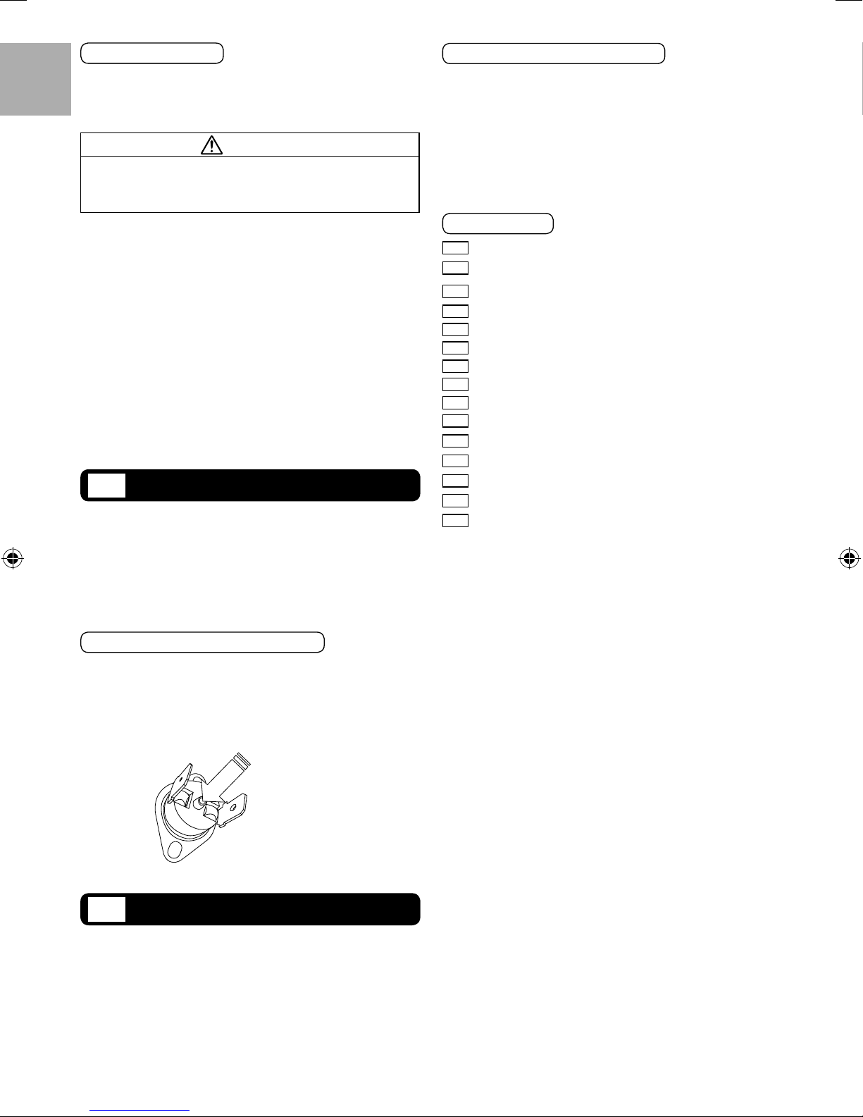
Refrigerant pipe installation
1. Please make fl are after inserting fl are nut (located at joint portion
of tube assembly) onto the copper pipe. (In case of using long
piping)
2. Do not use pipe wrench to open refrigerant piping. Flare nut
may be broken and cause leakage. Use proper spanner or ring
wrench.
3. Connect the piping:
Align the center of piping and suffi ciently tighten the fl are nut
•
with fi ngers.
Be sure to use two spanners to tighten the connection.
•
Further tighten the fl are nut with torque wrench in specifi ed
torque as stated in the table.
Spanner or
Wrench
Torque wrench
Piping size (Torque)
Gas Liquid
ø15.88mm (5/8")
[65 N•m]
Liquid Refrigerant Pipe
ø9.52mm (3/8")
[42 N•m]
Gas Refrigerant Pipe
CAUTION
Do not over tighten, over tightening cause water leakage.
CAUTION
Please take extra precaution when open the control board
cover 6 and control board 7 for indoor unit installation and
servicing. Failure to do so may cause injury.
If non-brass metallic piping is used for installation, make sure to
•
insulate the pipes to prevent galvanic corrosion.
Make sure to insulate the water circuit pipes to prevent reduction
•
of heating capacity.
5
CUTTING AND FLARING
THE PIPING
ENGLISH
1.
Please cut using pipe cutter and then remove the burrs.
2.
Remove the burrs by using reamer. If burrs is not removed, gas leakage
may be caused. Turn the piping end down to avoid the metal powder
entering the pipe.
3.
Please make fl are after inserting the fl are nut onto the copper pipes.
Pipe
Reamer
Point down
1. To cut 2. To remove burrs 3. To fl are
Improper fl aring
Inclined Surface
damaged
Cracked Uneven
Clamp handle
thickness
Drain elbow and hose installation
Fix the drain elbow 2 and packing 3 to the bottom of indoor unit,
•
as shown in below illustration.
Use inner diameter 17 mm drain hose in the market.
•
This hose must to be installed in a continuosly downward direction
•
and in a frost-free environment.
Guides this hose’s outlet to outdoor only.
•
Do not insert this hose into sewage or drain pipe that may generate
•
ammonia gas, sulfuric gas, etc.
If necessary, use hose clamp to further tighten the hose at drain
•
hose connector to prevent leakage.
Water will drip from this hose, therefore the outlet of this hose must
•
be installed in an area where the outlet cannot become blocked.
Packing
Drain elbow
3
2
Pressure Relief Valve Drainage Pipework
Connect a drain hose to the pressure relief valve hose outlet.
•
This hose must to be installed in a continuosly downward direction
•
and in a frost-free environment.
Guides this hose’s outlet to outdoor only.
•
Do not insert this hose into sewage hose or cleaning hose that may
•
generate ammonia gas, sulfuric gas, etc.
If necessary, use hose clamp to further tighten the hose at drain
•
hose connector to prevent leakage.
Water will drip from this hose, therefore the outlet of this hose must
•
be installed in an area where the outlet cannot become blocked.
Pressure relief valve
hose outlet
Handle
Bar
When properly fl ared, the internal surface
of the fl are will evenly shine and be of even
thickness. Since the fl are part comes into
contact with the connections, carefully check
the fl are fi nish.
Yoke
Core
Red arrow mark
Bar
0 – 0.5 mm
Copper
pipe
CONNECT THE CABLE TO
6
THE INDOOR UNIT
WARNING
This section is for authorised and licensed electrician only. Work
behind the Control Board Cover 6 secured by screws must
only be carried out under supervision of qualifi ed contractor,
installation engineer or service person.
Open the Control Board Cover 6
Please follow the steps below to open control board cover. Before
opening the control board cover of indoor unit, always switch off all
power supply (i.e. indoor unit power supply, heater power supply
and Tank Unit power supply).
1. Remove the 6 mounting screws at the control board cover.
2. Swing the control board cover to the right hand side.
Screws
Screws
Fixing of Power Supply Cord and Connecting Cable
1. Connecting cable between Indoor Unit and Outdoor Unit shall be
approved polychloroprene sheathed 4 x 1.5 mm
type designation 60245 IEC 57 or heavier cord.
Ensure the colour of wires of Outdoor Unit and the terminal
•
no. are the same to the Indoor Unit respectively.
Earth wire shall be longer than other wires as shown in the
•
fi gure for the electrical safety in case of the slipping out of the
cord from the Holder (Clamper).
2. An isolating device must be connected to the power supply
cable.
Isolating device (disconnecting means) should have minimum
•
3.0 mm contact gap.
Connect the approved polychloroprene sheathed power
•
supply 1 cord and power supply 2 cord and type designation
60245 IEC 57 or heavier cord to the terminal board, and to
the other end of the cord to isolating device (Disconnecting
means). See below table for cable size requirement.
For model S*C09*3E8
Power Supply
Cord
1 5 x minimum 1.5 mm
2 3 x minimum 1.5 mm2 15/16A 30mA, 2P, type AC
For model S*C12/16*9E8
Power Supply
Cord
1 5 x minimum 1.5 mm
2 5 x minimum 1.5 mm220A 30mA, 4P, type AC
3. To avoid the cable and cord being damaged by sharp edges, the
cable and cord must be passed through a bushing (located at
the bottom of Control Board) before terminal board. The bushing
must be used and must not be removed.
Cable Size
Cable Size
Isolating
Devices
2
20A 30mA, 4P, type A
Isolating
Devices
2
20A 30mA, 4P, type A
2
fl exible cord,
Recommended
RCD
Recommended
RCD
6
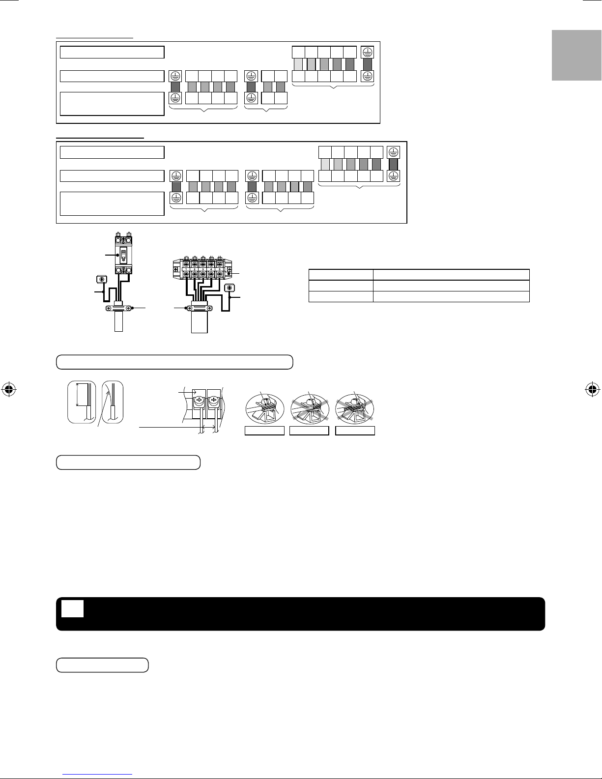
For model S*C09*3E8
ENGLISH
Terminal on the outdoor unit 1 2345
Colour of wires (Connecting cables)
Terminal on the indoor unit LA1LA2LA3N LN 12345
(Power Supply Cord)
Terminals on the isolating device
from power supply (Disconnecting
means)
Main Power Supply
or Main + Backup
Heater Power Supply
LA1LA2LA3N LN
Power Supply 1
Booster Heater
Power Supply
Power Supply 2
Indoor unit/Outdoor unit
connection
For model S*C12/16*9E8
Terminal on the outdoor unit 1 2345
Colour of wires (Connecting cables)
Terminal on the indoor unit LA1LA2LA3N LB1LB2LB3N 12345
(Power Supply Cord)
Terminals on the isolating device
from power supply (Disconnecting
means)
RCCB/ELCB
*1
(Clamper)
Main Power Supply
LA1LA2LA3N LB1LB2LB3N
Power Supply 1 Power Supply 2
Holder
Booster + Backup
Heater Power Supply
Terminal Board
*1
Indoor unit/Outdoor unit
connection
Terminal screw Tightening torque cN•m {kgf•cm}
M4 157~196 {16~20}
M5 196~245 {20~25}
*1 - Earth wire must be longer than other cables for safety reasons
Power Supply Cord
Connecting Cable
WIRE STRIPPING AND CONNECTING REQUIREMENT
Wire stripping
10 ± 1mm
No loose strand
when insert
Indoor/outdoor
connecting
terminal board
5mm or
more
(gap between
wires)
Conductor
fully insert
ACCEPT PROHIBITED
Conductor
over insert
Conductor not
fully insert
PROHIBITED
CONNECTING REQUIREMENT
For S*C09*3E8
The equipment’s Power Supply 1 complies with IEC/EN 61000-3-2.
•
The equipment’s Power Supply 1 complies with IEC/EN 61000-3-3 and can be connected to current supply network.
•
The equipment’s Power Supply 2 complies with IEC/EN 61000-3-2.
•
The equipment’s Power Supply 2 complies with IEC/EN 61000-3-11 and shall be connected to suitable supply network, with the following
•
maximum permissible system impedance Z
2 is connected only to a supply of that impedance or less.
= 0.426 at the interface. Please liaise with supply authority to ensure that the Power Supply
max
For S*C12*9E8/S*C16*9E8
The equipment’s Power Supply 1 complies with IEC/EN 61000-3-2.
•
The equipment’s Power Supply 1 complies with IEC/EN 61000-3-3 and can be connected to current supply network.
•
The equipment’s Power Supply 2 complies with IEC/EN 61000-3-2.
•
The equipment’s Power Supply 2 complies with IEC/EN 61000-3-3 and can be connected to current supply network.
•
INSTALLATION OF REMOTE CONTROLLER AS ROOM
7
THERMOSTAT
Remote Controller 3 mounted to the Indoor Unit can be moved to the room and serve as Room Thermostat.
•
Installation Location
Install at the height of 1 to 1.5 m from the fl oor (Location where average room temperature can be detected).
•
Install vertically against the wall.
•
Avoid the following locations for installation.
•
1. By the window, etc. exposed to direct sunlight or direct air.
2. In the shadow or backside of objects deviated from the room airfl ow.
3. Location where condensation occurs (The Remote Controller is not moisture proof or drip proof.)
4. Location near heat source.
5. Uneven surface.
Keep distance of 1 m or more from the TV, radio and PC. (Cause of fuzzy image or noise)
•
7
Remote Controller Wiring
Indoor unit
ENGLISH
Remote Controller wiring
(fi eld supply)
No polarity
•
Remote Controller
Terminal for Remote Controller wiring
Remote Controller cable shall be (2 x min 0.3 mm²), of double
•
insulation PVC-sheathed or rubber sheathed cable. Total cable
length shall be 50 m or less.
Be careful not to connect cables to other terminals of Indoor Unit
•
(e.g. power source wiring terminal). Malfunction may occur.
Do not bundle together with the power source wiring or store in the
•
same metal tube. Operation error may occur.
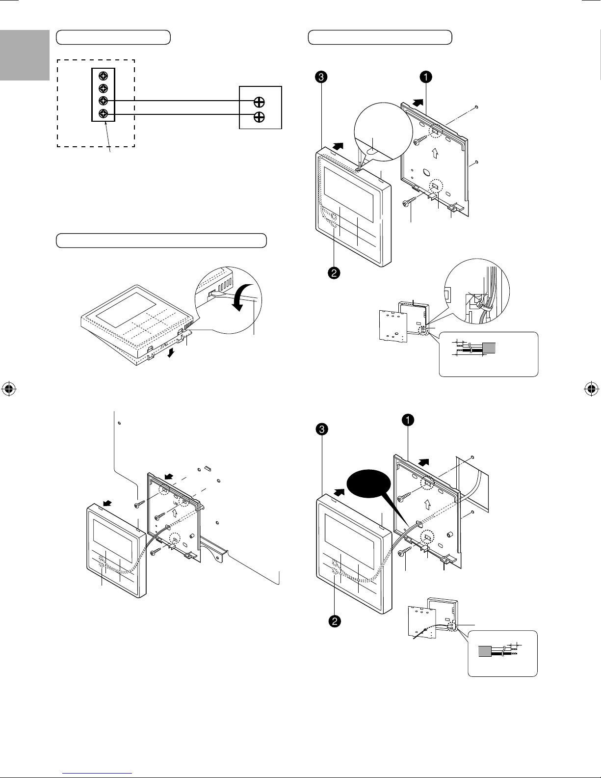
Remove The Remote Controller From Indoor Unit
1. Remove the top case from the bottom case.
Insert the
driver and
slightly turn.
Flat-blade
Bottom
case
2. Remove the wiring between Remote controller and Indoor Unit
terminal. Remove the bottom case from the Control board cover
by loosening the screws. (3 pieces)
screwdriver
Mounting The Remote Controller
For exposed type
Preparation: Make 2 holes for screws using a driver.
Mount the top case.
Align the claws of the top
•
case and then align the claws
of the bottom case.
1
2
Cut here with
a nipper and
remove the burr
with a fi le.
Claw (2 places)
Screw
(fi eld supply)
Connect the remote control
wiring
Arrange the wires along the groove
•
of the case.
Bottom case
(Back side)
For embedded type
Preparation: Make 2 holes for screws using a driver.
Mount the top case.
Align the claws of the top
•
case and then align the claws
of the bottom case.
Mount the bottom case to
the wall.
UP
Hole for screw
Claw (2 places)
(fi eld supply)
Pass through
the hole
Remote controller terminal board
Top case
(Back side)
Remove the coating. Approx. 6 mm
Remove the sheath. Approx. 180 mm.
Make sure the wiring connection is in the
correct direction.
Mount the bottom case
to the wall.
Pass the wire through the hole
•
in the centre of the bottom case.
Wall to which
the remote
controller is
fi xed
Clamper
Claw
(2 places)
Disconnect the
Remote controller
wiring
8
Avoid the wire
being caught.
Claw (2 places)
Screw
(fi eld supply)
Connect the remote
control wiring
UP
Hole for
screw
Bottom case
(Back side)
Claw (2 places)
Top case
(Back side)
Remote controller
terminal board
Remove the coating.
Approx. 6 mm
Make sure the wiring
connection is in the correct
direction.
Replace The Remote Controller Cover
Replace the existing Remote controller cover with Remote controller
•
cover 6 to close the hole left after remove the Remote controller.
1. Release the Remote controller cover’s hooks from behind the
front plate.
Front plate
RECONFIRMATION
9
WARNING
Be sure to switch off all power supply before performing each of
the below checkings. Before obtaining access to terminals, all
supply circuits must be disconnected.
ENGLISH
Existing Remote
controller cover
2. Press from front to fi x the Remote controller cover 6 on the
front plate.
Remote
controller
cover
6
CHARGING THE WATER
8
Make sure all the piping installations are properly done before
•
carry out below steps.
1. Turn the plug on the Air Purge Valve 9 outlet anticlockwise by
one complete turn from fully closed position.
Air purge valve
2. Set the Pressure Relief Valve c level “DOWN”.
Lever
Turn up
Pressure relief valve
3. Start fi lling water (with pressure more than 0.1 MPa (1 bar)) to
the Indoor Unit via water inlet. Stop fi lling water if the free water
fl ow through Pressure Relief Valve drain hose.
4. Turn ON the power supply and make sure Water Pump f is
running.
5. Check and make sure no water leaking at the tube connecting
points.
Hook (6 places)
Front plate
Hook (6 places)
Plug (turn
anticlockwise by
one complete turn)
9
Pressure relief
valve
c
c
CHECK WATER PRESSURE
Water pressure should not lower than 0.05 MPa (with inspects the
Water Pressure Gauge d). If necessary add tap water into Tank
Unit. Refer to Tank unit installation instruction for details on how to
add water.
*(0.1 MPa = 1 bar)
CHECK PRESSURE RELIEF VALVE c
Check for correct operation of Pressure Relief Valve c by turning
•
on the lever to become horizontal.
If you do not hear a clacking sound (due to water drainage), contact
•
your local authorized dealer.
Push down the lever after fi nish checking.
•
In case the water keeps drained out from the unit, switch off the
•
system, and then contact your local authorized dealer.
EXPANSION VESSEL b PRE PRESSURE CHECKING
[Lower limit water volume of the system]
Please ensure the capacity of the circulating water of the total
system including the capacity of the indoor unit is more than 50 L.
If the water capacity is insuffi cient, during deice operation, the water
temperature is lowered and the water will freeze in the system’s
component leading to product failure.
[Upper limit water volume of the system]
The indoor unit has a build-in Expansion Vessel with 10 L air
capacity and initial pressure of 1 bar.
Total amount of water in the system should be below 260 L.
If the total amount of water is more than 260 L, please add
expansion vessel (fi eld supply).
The expansion vessel capacity required for the system can be
calculated from the formula below.
V =
V : Required gas volume <expansion vessel volume L>
Vo
: System total water volume <L>
з
: Water expansion rate 5 60˚C = 0.0171
P1 : Expansion tank fi lling pressure = (100) kPa
P
: System maximum pressure = 300 kPa
2
- ( ) Please confi rm at actual place
- The gas volume of the sealed type expansion vessel is presented by <V>.
It’s advised to add 10% margin for required gas volume of calculation.
Water expansion rate table
Water temperature (°C) Water expansion rate
10 0.0003
20 0.0019
30 0.0044
40 0.0078
50 0.0121
60 0.0171
70 0.0228
80 0.0291
90 0.0360
[Adjustment of the initial pressure of the expansion vessel when
there is a difference in installation height]
If the height difference between the indoor unit and the highest
point of the system water circuit (H) is more than 7m, please adjust
the initial pressure of the expansion vessel (Pg) according to the
following formula.
з
x
Vo
98 +
P
98 +
1
P
2
1 -
Pg= (H*10+30) kPa
9
CHECK RCCB/ELCB
Ensure the RCCB/ELCB set to “ON” condition before check RCCB/
ELCB.
Turn on the power supply to the Indoor Unit.
ENGLISH
This testing could only be done when power is supplied to the
Indoor Unit.
WARNING
Be careful not to touch parts other than RCCB/ELCB test button
when the power is supplied to Indoor Unit. Else, electrical shock
may happen. Before obtaining access to terminals, all supply
circuits must be disconnected.
Push the “TEST” button on the RCCB/ELCB. The lever would turn
•
down and indicate “0”, if it functions normal.
Contact authorized dealer if the RCCB/ELCB malfunction.
•
Turn off the power supply to the Indoor Unit.
•
If RCCB/ELCB functions normal, set the lever to “ON” again after
•
testing fi nish.
This product contains fl uorinated greenhouse gasses.
Refrigerant type : R410A (GWP=2088)
Amount : For SXC09*3E8/SXC12*9E8 2.85 kg (5.9508 ton CO
For SXC16*9E8 2.90 kg (6.0552 ton CO
For SDC09*3E8/SDC12*9E8/SDC16*9E8 2.55kg (5.3244
(The amount do not include the additional refrigerant when
refrigerating piping length extended. Please refer to adhered label
on outdoor unit for exact amount of refrigerant used and actual
tonnes of CO
1. Fill up the Tank Unit with water. For details refer to Tank Unit
2. Set ON to the Indoor Unit and RCCB/ELCB. Then, for control
3. For normal operation, pressure gauge d reading should be in
4. After test run, please clean the Water Filter Set e. Reinstall it
equivalent)
ton CO
equivalent)
2
equivalent.)
2
10
TEST RUN
installation instruction and operation instruction.
panel operation please refers to air-to-water heatpump operation
instruction.
between 0.05 MPa and 0.3 MPa.
after fi nish cleaning.
equivalent)
2
Maintenance for Water Filter Set e
1. Turn OFF power supply.
2. Set the two valves for the Water Filter Set e to “CLOSE”.
3. Take off the clip, then gently pull out the mesh. Beware of small
amount water drain out from it.
4. Clean the mesh with warm water to remove all the stain. Use
soft brush if necessary.
5. Reinstall the mesh to the Water Filter Set e and set back the
clip on it.
6. Set the two valves for the Water Filter Set e to “OPEN”.
7. Turn ON power supply.
CHECK ITEMS
Is there any gas leakage at fl are nut connections?
Has the heat insulation been carried out at fl are nut
connection?
Is the connecting cable fi xed to terminal board fi rmly?
Is the connecting cable clamped fi rmly?
2
Is the earth wire connection properly done?
Is water pressure higher than 0.05 MPa?
Is the pressure relief valve c operation normal?
Is the RCCB/ELCB operation normal?
Is the Indoor Unit properly hooked to the installation plate?
Is the power supply voltage within the rated voltage range?
Is there any abnormal sound?
Is the heating operation normal?
Is the thermostat operation normal?
Is the remote controller 3 LCD operation normal?
Is the Indoor Unit water leak free on test run?
RESET OVERLOAD PROTECTOR a
Overload Protector a serves the safety purpose to prevent the
water over heating. When the Overload Protector a trip at high
water temperature, take below steps to reset it.
1. Take out the cover.
2. Use a test pen to push the centre button gently in order to reset
the Overload Protector a.
3. Fix the cover to the original fi xing condition.
11
•
MAINTENANCE
In order to ensure safety and optimal performance of the unit,
seasonal inspections on the unit, functional check of RCCB/ELCB,
fi eld wiring and piping have to be carried out at regular intervals. This
maintenance should be carried out by authorized dealer. Contact
dealer for scheduled inspection.
Use test pen to push
this button for reset
Overload protector a.
10
APPENDIX
1
Variation of system
This section introduces variation of various systems using Air-To-Water Heatpump and actual setting method.
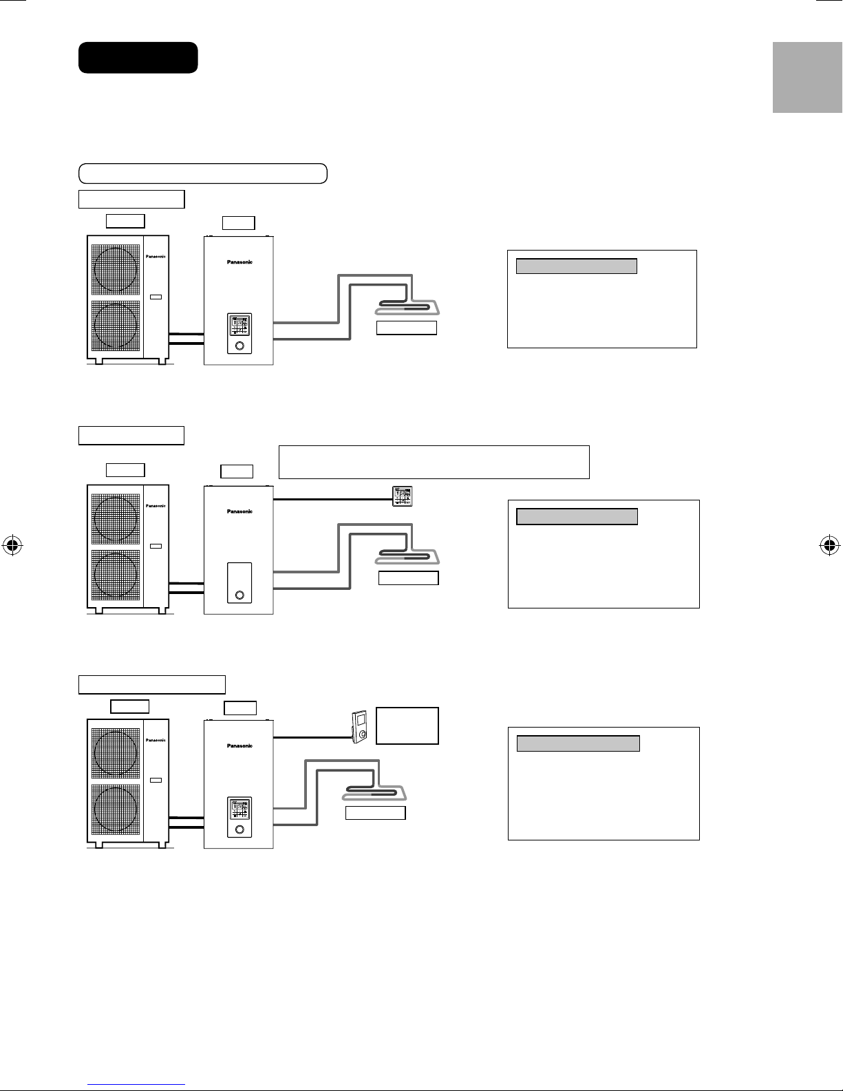
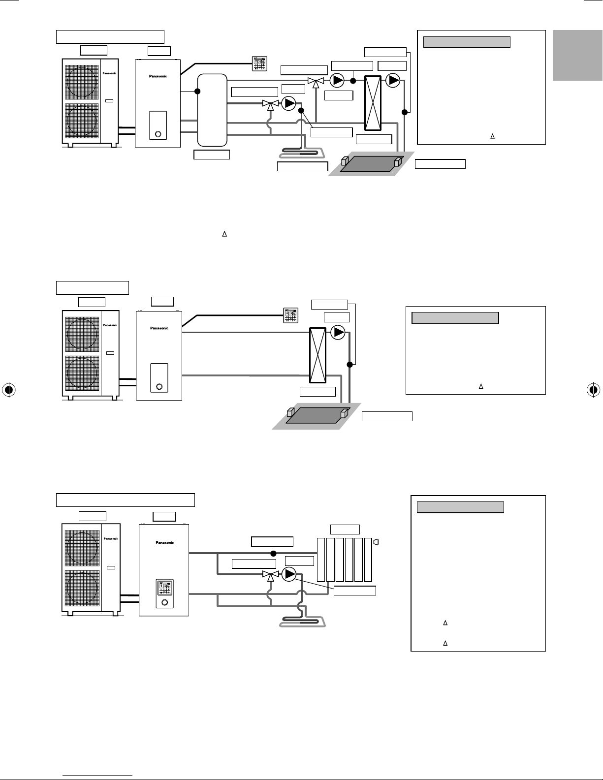
1-1 Introduce application related to temperature setting.
Temperature setting variation for heating
1. Remote Controller
Outdoor
Connect fl oor heating or radiator directly to the indoor unit.
Remote controller is installed on indoor unit.
This is the basic form of the most simple system.
2. Room Thermostat
Outdoor
Indoor
Indoor
Setting of remote controller
Installer setting
System setup
Optional PCB connectivity - No
Floor heating
Indoor unit receive Room Thermo signal (ON/OFF) from Remote controller
to control HP and circulation pump.
There is a build-in thermistor in the remote controller.
Zone & Sensor:
Water temperature
ENGLISH
Setting of remote controller
Installer setting
System setup
Optional PCB connectivity - No
Floor heating
Zone & Sensor:
Connect fl oor heating or radiator directly to the indoor unit.
Remove remote controller from indoor unit and install it in the room where fl oor heating is installed.
This is an application that uses remote controller as Room Thermostat.
3. External Room Thermostat
Outdoor
Indoor
Room
Thermostat
(Field supply)
Floor heating
Setting of remote controller
Installer setting
System setup
Optional PCB connectivity - No
Zone & Sensor:
Connect fl oor heating or radiator directly to indoor unit.
Remote controller is installed on indoor unit.
Install separate external Room Thermostat (fi eld supply) in the room where fl oor heating is installed.
This is an application that uses external Room Thermostat.
Room thermostat
Internal
Room thermostat
(External)
11
4. Room Thermistor
ENGLISH
Outdoor
Indoor
Indoor unit compare between room temperature and setting temperature
on the Remote controller to control HP and circulation pump.
Max: 30m
Thermistor
Floor heating
Connect fl oor heating or radiator directly to indoor unit.
Remote controller is installed on indoor unit.
Install separate external room thermistor (specifi ed by Panasonic) in the room where fl oor heating is installed.
This is an application that uses external room thermistor.
There are 2 kinds of circulation water temperature setting method.
Direct: set direct circulation water temperature (fi xed value)
Compensation curve: set circulation water temperature depends on outdoor ambient temperature
In case of Room thermo or Room thermistor, compensation curve can be set.
In this case, compensation curve is shifted according to the thermo ON/OFF situation.
(Example) If room temperature increasing speed is;
•
very slow shift up the compensation curve
very fast shift down the compensation curve
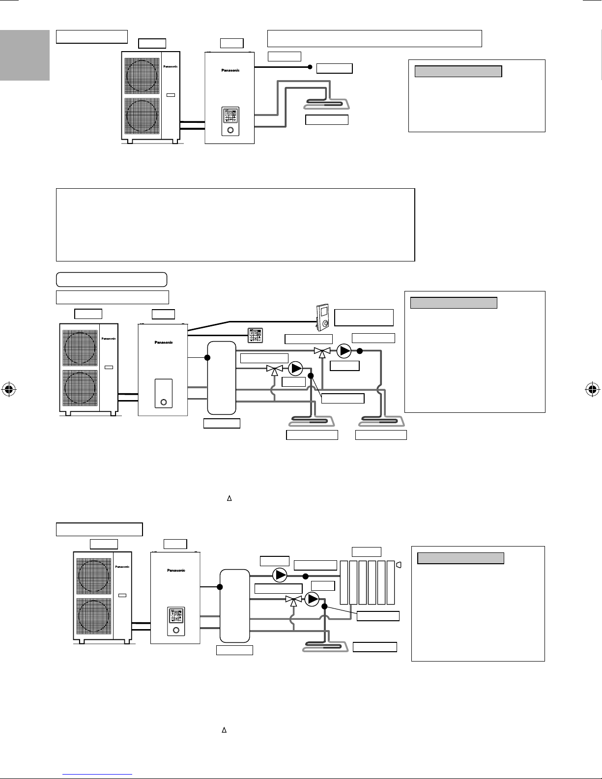
Examples of installations
Setting of remote controller
Installer setting
System setup
Optional PCB connectivity - No
Zone & Sensor:
Room thermistor
Floor heating 1 + Floor heating 2
Outdoor
Indoor
Mixing valve 2
Mixing valve 1
Pump 1
Buffer tank
Room Thermostat
(fi eld supply)
Thermistor 2
Pump 2
Thermistor 1
Floor heating 2Floor heating 1
Connect fl oor heating to 2 circuits through buffer tank as shown in the fi gure.
Install mixing valves, pumps and thermistors (specifi ed by Panasonic) on both circuits.
Remove remote controller from indoor unit, install it in one of the circuit and use it as Room Thermostat.
Install external Room Thermostat (fi eld supply) in another circuit.
Both circuits can set circulation water temperature independently.
Install buffer tank thermistor on buffer tank.
It requires connection setting of buffer tank and
T temperature setting at heating operation separately.
This system requires optional PCB (CZ-NS4P).
Floor heating + Radiator
Outdoor
Indoor
Pump 2
Mixing valve 1
Radiator
Thermistor 2
Pump 1
Thermistor 1
Setting of remote controller
Installer setting
System setup
Optional PCB connectivity - Yes
Zone and Sensor - 2 Zone system
Zone 1:Sensor
Room thermostat
Internal
Zone 2:Sensor
Room
Room thermostat
Setting of remote controller
Installer setting
System setup
Optional PCB connectivity - Yes
Zone and Sensor - 2 Zone system
Zone 1:Sensor
Water temperature
(External)
Connect fl oor heating or radiator to 2 circuits through buffer tank as shown in fi gure.
Install pumps and thermistors (specifi ed by Panasonic) on both circuits.
Install mixing valve in the circuit with lower temperature among the 2 circuits.
(Generally, if install fl oor heating and radiator circuit at 2 zones, install mixing valve in fl oor heating circuit.)
Remote controller is installed on indoor unit.
For temperature setting, select circulation water temperature for both circuits.
Both circuits can set circulation water temperature independently.
Install buffer tank thermistor on buffer tank.
It requires connection setting of buffer tank and
This system requires the optional PCB (CZ-NS4P).
Mind that if there is no mixing valve at the secondary side, the circulation water temperature may get higher than setting temperature.
12
Buffer tank
Floor heating
T temperature setting at heating operation separately.
Zone 2:Sensor
Room
Water temperature
Floor heating + Swimming pool
Outdoor
Indoor
Buffer tank
Mixing valve 1
Mixing valve 2
Pump 1
Thermistor 1
Floor heating 1
Thermistor 2
Pump 2
Thermistor 3
Pump 3
Heat EXT
Setting of remote controller
Installer setting
System setup
Optional PCB connectivity - Yes
Zone and Sensor - 2 Zone system
Zone 1:Sensor
Room thermostat
Zone 2
Swimming pool
Swimming pool
Internal
T
Connect fl oor heating and swimming pool to 2 circuits through buffer tank as shown in fi gure.
Install mixing valves, pumps and thermistors (specifi ed by Panasonic) on both circuits.
Then, install additional pool heat exchanger, pool pump and pool sensor on pool circuit.
Remove remote controller from indoor unit and install in room where fl oor heating is installed. Circulation water temperature of fl oor heating
and swimming pool can be set independently.
Install buffer tank sensor on buffer tank.
It requires connection setting of buffer tank and
T temperature setting at heating operation separately. This system requires the optional
PCB (CZ-NS4P).
Must connect swimming pool to “Zone 2”.
If it is connected to swimming pool, operation of pool will stop when “Cooling” is operated.
Swimming pool only
Outdoor
Indoor
Thermistor
Heat EXT
Pump
Setting of remote controller
Installer setting
System setup
Optional PCB connectivity - Yes
Zone and Sensor - 1 Zone system
Zone :Swimming pool
T
ENGLISH
This is an application that connects to the swimming pool only.
Connects pool heat exchanger directly to indoor unit without
Swimming pool
using buffer tank.
Install pool pump and pool sensor (specifi ed by Panasonic) at secondary side of the pool heat exchanger.
Remove remote controller from indoor unit and install in room where fl oor heating is installed.
Temperature of swimming pool can be set independently.
This system requires the optional PCB (CZ-NS4P).
In this application, cooling mode cannot be selected. (not display on remote controller)
Simple 2 zone (Floor heating + Radiator)
Outdoor
Indoor
Thermistor 1
Mixing valve
Radiator
Pump 2
Thermistor 2
This is an example of simple 2 zone control without using buffer tank.
Built-in pump from indoor unit served as a pump in zone 1.
Install mixing valve, pump and thermistor (specifi ed by Panasonic) on zone 2 circuit.
Please be sure to assign high temperature side to zone 1 as temperature of zone 1 cannot be adjusted.
Zone 1 thermistor is required to display temperature of zone 1 on remote controller.
Circulation water temperature of both circuits can be set independently.
(However, temperature of high temperature side and low temperature side cannot be reversed)
This system requires the optional PCB (CZ-NS4P).
Setting of remote controller
Installer setting
System setup
Optional PCB connectivity - Yes
Zone and Sensor - 2 Zone system
Zone 1:Sensor
Water temperature
Zone 2:Sensor
Room
Water temperature
Operation setup
Heat
T for heating ON – 1°C
Cool
T for cooling ON – 1°C
(CAUTION)
Thermistor 1 does not affect operation directly. But error happens if it is not installed.
•
Please adjust fl ow rate of zone 1 and zone 2 to be in balance. If it is not adjusted correctly, it may affects the performance.
•
(If zone 2 pump fl ow rate is too high, there is possibility that no hot water fl owing to zone 1.)
Flow rate can be confi rmed by “Actuator Check” from maintenance menu.
13
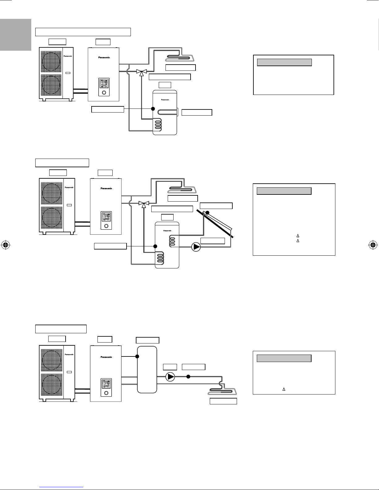
1-2. Introduce applications of system that uses optional equipment.
DHW (Domestic Hot Water) Tank connection
ENGLISH
Outdoor
Indoor
Floor heating
3-way valve for tank
Tank
Tank thermistor
Booster heater
This is an application that connects the DHW tank to the indoor unit through 3-way valve.
DHW tank’s temperature is detected by tank thermistor (specifi ed by Panasonic).
Tank + Solar connection
Outdoor
Indoor
Tank thermistor
Floor heating
3-way valve for tank
Tank
Solar thermistor
Solar pump
Setting of remote controller
Installer setting
System setup
Optional PCB connectivity - No
Tank connection - Yes
Setting of remote controller
Installer setting
System setup
Optional PCB connectivity - Yes
Tank connection - Yes
Solar connection - Yes
DHW tank
Antifreeze
Hi limit
T turn ON
T turn OFF
This is an application that connects the DHW tank to the indoor unit through 3-way valve before connect the solar water heater to heat up
the tank. DHW tank’s temperature is detected by tank thermistor (specifi ed by Panasonic). Solar panel’s temperature is detected by solar
thermistor (specifi ed by Panasonic).
DHW tank shall use tank with built-in solar heat exchange coil independently.
Heat accumulation operates automatically by comparing the temperature of tank thermistor and solar thermistor.
During winter season, solar pump for circuit protection will be activated continuously. If does not want to activate the solar pump operation,
please use glycol and set the anti-freezing operation start temperature to -20°C.
This system requires optional PCB (CZ-NS4P).
Buffer tank connection
Outdoor
Indoor
Buffer tank
Pump
Thermistor
Floor heating
Setting of remote controller
Installer setting
System setup
Optional PCB connectivity - Yes
Buffer Tank connection - Yes
T for buffer tank
This is an application that connects the buffer tank to the indoor unit.
Buffer tank’s temperature is detected by buffer tank thermistor (specifi ed by Panasonic).
This system requires optional PCB (CZ-NS4P).
14

Buffer tank + Solar
Outdoor
Indoor
Buffer tank
Solar pump
Mixing valve
Solar thermistor
Pump
Floor heating
Thermistor
Setting of remote controller
Installer setting
System setup
Optional PCB connectivity - Yes
Buffer Tank connection - Yes
T for buffer tank
Solar connection - Yes
Buffer tank
Antifreeze
Hi limit
T turn ON
T turn OFF
This is an application that connects the buffer tank to the indoor unit before connecting to the solar water heater to heat up the tank.
Buffer tank’s temperature is detected by buffer tank thermistor (specifi ed by Panasonic).
Solar panel’s temperature is detected by solar thermistor (specifi ed by Panasonic).
Buffer tank shall use tank with built-in solar heat exchange coil independently.
During winter season, solar pump for circuit protection will be activated continuously. If does not want to activate the solar pump operation,
please use glycol and set the anti-freezing operation start temperature to -20°C.
Heat accumulation operates automatically by comparing the temperature of tank thermistor and solar thermistor.
This system requires optional PCB (CZ-NS4P).
Boiler connection
Outdoor
Indoor
Buffer tank
ENGLISH
Boiler
Mixing
valve
Pump
Thermistor
Floor heating
Setting of remote controller
Installer setting
System setup
Optional PCB connectivity - Yes
Bivalent - Yes
Turn ON: outdoor temp
Control pattern
This is an application that connects the boiler to the indoor unit, to compensate for insuffi cient capacity by operate boiler when outdoor
temperature drops & heat pump capacity is insuffi cient.
Boiler is connected parallel with heat pump against heating circuit.
There are 3 modes selectable by remote controller for boiler connection.
Besides that, an application that connects to the DHW tank’s circuit to heat up tank’s hot water is also possible.
(Operation setting of boiler shall be responsible by installer.)
This system requires optional PCB (CZ-NS4P).
Depending on the settings of the boiler, it is recommended to install buffer tank as temperature of circulating water may get higher. (It must
connect to buffer tank especially when selecting Advanced Parallel setting.)
WARNING
Panasonic is NOT responsible for incorrect or unsafe situation of the boiler system.
CAUTION
Make sure the boiler and its integration in the system complies with applicable legislation.
Make sure the return water temperature from the heating circuit to the indoor unit does NOT exceed 55°C.
Boiler is turned off by safety control when the water temperature of the heating circuit exceed 85°C.
2
How to fi x cable
Connecting with external device (optional)
All connections shall follow to the local national wiring standard.
•
It is strongly recommended to use manufacturer-recommended parts and accessories for installation.
•
For connection to main PCB 4
•
Two-way valve shall be spring and electronic type, refer to “Field Supply Accessories” table for details. Valve cable shall be (3 x min 1.5 mm2),
1.
of type designation 60245 IEC 57 or heavier, or similarly double insulation sheathed cable.
* note: - Two-way Valve shall be CE marking compliance component.
2. Three-way valve shall be spring and electronic type. Valve cable shall be (3 x min 1.5 mm2), of type designation 60245 IEC 57 or heavier,
3. Room thermostat cable must be (4 or 3 x min 0.5 mm2), of type designation 60245 IEC 57 or heavier cord, or similarly double insulation
4. Maximum output power of booster heater shall be ≤ 3 kW. Booster heater cable must be (3 x min 1.5 mm2), of type designation 60245 IEC
- Maximum load for the valve is 9.8VA.
or similarly double insulation sheathed cable.
* note: - Shall be CE marking compliance component.
- It shall be directed to heating mode when it is OFF.
- Maximum load for the valve is 9.8VA.
sheathed cable.
57 or heavier.
15
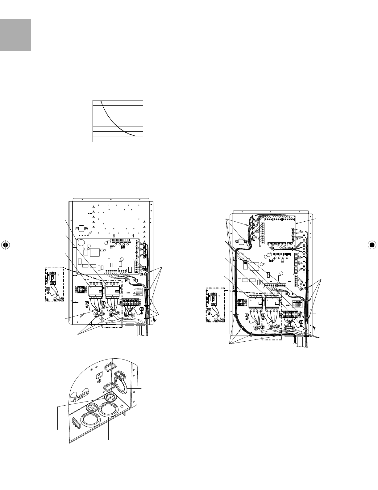
5. Extra pump cable shall be (2 x min 1.5 mm²), of type designation
60245 IEC 57 or heavier.
6. Boiler contact cable shall be (2 x min 0.5 mm²), of type
designation 60245 IEC 57 or heavier.
7. External control shall be connected to 1-pole switch with min
ENGLISH
3.0 mm contact gap. Its cable must be (2 x min 0.5 mm
2
), double
insulation layer of PVC-sheathed or rubber-sheathed cable.
* note: - Switch used shall be CE compliance component.
- Maximum operating current shall be less than 3A
rms
8. Tank sensor shall be resistance type, please refer to Graph 7.1 for
the characteristic and details of sensor. Its cable shall be (2 x min
2
0.3 mm
), double insulation layer (with insulation strength of min
30V) of PVC-sheathed or rubber-sheathed cable.
Tank Sensor Resistance Vs Temperature
16000
14000
12000
10000
8000
6000
4000
Resistance
2000
0
-30 -20 -10 0 10 20 30
Tank sensor characteristic
˚C
9. Room sensor zone 1 cable shall be (2 x min 0.3 mm²) double
insulation layer of PVC-sheathed or rubber-sheathed.
10. Outdoor air sensor cable shall be (2 x min 0.3 mm²) double
insulation layer of PVC-sheathed or rubber-sheathed.
11. Tank OLP cable must be (2 x min 0.5 mm
2
), double insulation
layer of PVC-sheathed or rubber-sheathed cable.
Main PCB 4
Power Supply 2
RCCB/ELCB
Power Supply 1
RCCB/ELCB
Bind optional
cables with
these bands
For connection to optional PCB
•
7
1. By connecting optional PCB, 2 Zone temperature control can
be achieved. Please connect mixing valves, water pumps and
thermistors in zone 1 and zone 2 to each terminals in optional
PCB.
Temperature of each zone can be controlled independently by
remote controller.
2.
.
designation 60245 IEC 57 or heavier.
Pump zone 1 and zone 2 cable shall be (2
x min 1.5 mm²), of type
3. Solar pump cable shall be (2 x min 1.5 mm²), of type designation
60245 IEC 57 or heavier.
4. Pool pump cable shall be (2 x min 1.5 mm²), of type designation
60245 IEC 57 or heavier.
5. Room thermostat zone 1 and zone 2 cable shall be (4 x min
0.5 mm²), of type designation 60245 IEC 57 or heavier.
6. Mixing valve zone 1 and zone 2 cable shall be (3 x min 1.5 mm²),
of type designation 60245 IEC 57 or heavier.
7. Room sensor zone 1 and zone 2 cable shall be (2 x min 0.3 mm²),
double insulation layer (with insulation strength of minimum 30V)
of PVC-sheathed or rubber-sheathed cable.
8. Buffer tank sensor, pool water sensor and solar sensor cable
shall be (2 x min 0.3 mm²), double insulation layer (with insulation
strength of minimum 30V) of PVC-sheathed or rubber-sheathed
cable.
9. Water sensor zone 1 and zone 2 cable shall be (2 x min 0.3 mm²),
double insulation layer of PVC-sheathed or rubber-sheathed cable.
10. Demand signal cable shall be (2 x min 0.3 mm²), double insulation
layer of PVC-sheathed or rubber-sheathed cable.
11. SG signal cable shall be (3 x min 0.3 mm²), double insulation layer
of PVC-sheathed or rubber-sheathed cable.
12. Heat/Cool switch cable shall be (2 x min 0.3 mm²), double insulation
layer of PVC-sheathed or rubber-sheathed cable.
13. External compressor switch cable shall be (2 x min 0.3 mm²),
double insulation layer of PVC-sheathed or rubber-sheathed cable.
Bind all
optional cables
with these
bands
Bind optional
cables with
these bands
Power Supply 2
RCCB/ELCB
Power Supply 1
RCCB/ELCB
Optional
PCB 7
Bind optional
cables with
these bands
For S*C09*3E8
Indoor terminal
for connecting
cables
Holder (Clamper)
For S*C12/16*9E8
How to guide the optional cables and power supply cord
(view without internal wiring)
Optional cables:
3-way valve
•
cable
2-way valve cable
•
Room thermostat zone
•
1 cable
Booster heater cable
•
Extra pump cable
•
Boiler contact cable
•
16
Power Supply 1 cord
•
Power Supply 2 cord
•
Indoor Unit/Outdoor Unit Connecting cable
•
Bind optional
cables with
these bands
Optional cables:
External control
•
cable
Tank sensor cable
•
Room sensor
•
zone 1
Outdoor air sensor
•
cable
Tank OLP cable
•
Remote controller
•
cable
For S*C09*3E8
Bind all optional
cables with these
bands
For S*C12/16*9E8
How to guide the optional cables and power supply cord
(view without internal wiring)
Indoor
terminal for
connecting
cables
Holder (Clamper)
Optional cables:
3-way valve cable
•
2-way valve cable
•
Booster heater cable
•
Extra pump cable
•
Boiler contact cable
•
Optional cables:
Pump zone 1 cable
•
Pump zone 2 cable
•
Solar pump cable
•
Pool pump cable
•
Room thermostat zone 1 cable
•
Room thermostat zone 2 cable
•
Mixing valve zone 1 cable
•
Mixing valve zone 2 cable
•
Optional cables:
External control cable
•
Tank sensor cable
•
Outdoor air sensor cable
•
Tank OLP cable
•
Remote controller cable
•
Room sensor zone 1 cable
•
Room sensor zone 2 cable
•
Buffer tank sensor cable
•
Pool sensor cable
•
Water sensor zone 1 cable
•
Water sensor zone 2 cable
•
Demand signal cable
•
Solar sensor cable
•
SG signal cable
•
Heat/Cool switch cable
•
External Compressor switch cable
•
from optional PCB
Power Supply 1 cord
•
Power Supply 2 cord
•
Indoor Unit/Outdoor
•
Unit Connecting cable
from optional
PCB
Terminal screw on PCB Maximum tightening torque cN•m {kgf•cm}
M3 50 {5.1}
M4 120 {12.24}
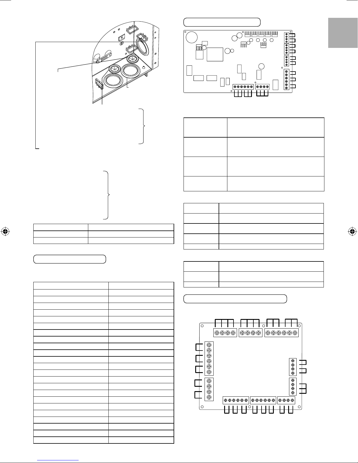
Connection of the main PCB
H C N LC O N C O N
3-way
valve
Optional
Thermostat 1
2-way
valve
Signal inputs
L N =AC230V, Heat, Cool=Thermostat heat, Cool
Optional Thermostat
OLP for booster
heater
External control
Remote controller
terminal
It does not function when using the optional
PCB
Dry contact Vcc-Bit1, Vcc-Bit2 open/short
(System setup necessary)
It is connected to the safety device (OLP) of
DHW tank.
Dry contact Open=not operate, Short=operate
(System setup necessary)
Able to turn ON/OFF the operation by external
switch
Connected (Please use 2 cores wire for relocation
and extension. Total cable length shall be 50m
or less.)
Outputs
3-way valve
2-way valve
Extra pump
Booster heater
AC230V N=Neutral Open, Close=direction (For
circuit switching when connected to DHW tank)
AC230V N=Neutral Open, Close (Prevent water
circuit pass through during cooling mode)
AC230V (Used when indoor unit pump capacity is
insuffi cient)
AC230V (Used when using booster heater in DHW
tank)
Boiler contact Dry contact (System setup necessary)
OLP for booster
heater
Zone 1 room sensor
Outdoor air sensor
Tank sensor
External control
Remote controller
Boiler contact
Extra pump
Booster heater
ENGLISH
Connecting Cables Length
When connecting cables between Indoor Unit and external devices,
the length of the said cables must not exceed the maximum length
as shown in the table.
External device Maximum cables length (m)
Two-way valve 50
Three-way valve 50
Mixing valve 50
Room thermostat 50
Booster heater 50
Extra pump 50
Solar pump 50
Pool pump 50
Pump 50
Boiler contact 50
External control 50
Tank sensor 30
Room sensor 30
Outdoor air sensor 30
Tank OLP 30
Buffer tank sensor 30
Pool water sensor 30
Solar sensor 30
Water sensor 30
Demand signal 50
SG signal 50
Heat/Cool switch 50
External compressor switch 50
Thermistor inputs
Zone 1 room
sensor
Outdoor air
sensor
PAW-A2W-TSRT It does not work when using
the optional PCB
AW-A2W-TSOD (Total cable length shall be 30m
or less)
Tank sensor Please use Panasonic specifi ed part
Connection of Optional PCB (CZ-NS4P)
Pool
water
Zone 2
water
sensor
Mixing
valve 1
Zone 1
water
sensor
Demand
signal
Pool
Pump
Solar
Pump
Error
signal
Zone 1
Pump
Zone 2
Pump
Optional
Thermostat 2
Zone 2
room
sensor
Zone 1
room
sensor
Optional
Thermostat 1
Buffer
Tank
sensor
sensor
Mixing
valve 2
N O CN O CL N Cool Heat L N Cool Heat
Solar
sensor
Ext.
comp.
SW
Heat/
Cool
SW
Vcc
Bit1
Bit2
SG
signal
17
Signal inputs
Optional Thermostat
ENGLISH
SG signal
Heat/Cool SW
External comp.SW
Demand signal
L N =AC230V, Heat, Cool=Thermostat heat, Cool
terminal
Dry contact Vcc-Bit1, Vcc-Bit2 open/short
(System setup necessary)
Switching SW (Please connect to the 2 contacts
controller)
Dry contact Open=Heat, Short=Cool (System
setup necessary)
Dry contact Open=Comp.ON, Short=Comp.OFF
(System setup necessary)
DC 0~10V (System setup necessary)
Please connect to the DC 0~10V controller.
Outputs
Mixing valve
Pool pump AC230V
Solar pump AC230V
Zone pump AC230V
AC230V N=Neutral Open, Close=mixture direction
Operating time: 30s~120s
Thermistor inputs
Zone room
sensor
Buffer tank
sensor
Pool water
sensor
Zone water
sensor
Solar sensor PAW-A2W-TSSO
PAW-A2W-TSRT
PAW-A2W-TSBU
PAW-A2W-TSHC
PAW-A2W-TSHC
Recommended External Device Specifi cation
This section explains about the external devices (optional)
•
recommended by Panasonic. Please always ensure to use the
correct external device during system installation.
For optional sensor.
•
1. Buffer tank sensor: PAW-A2W-TSBU
Use for measurement of the buffer tank temperature.
Insert the sensor into the sensor pocket and paste it on the
buffer tank surface.
2. Zone water sensor: PAW-A2W- TSHC
Use to detect the water temperature of the control zone.
Mount it on the water piping by using the stainless steel metal
strap and contact paste (both are included).
Dimensions (mm)
Dimensions (mm)
blue
brown
black
40
93
Ø6
4. Room sensor: PAW-A2W- TSRT
Install the room temperature sensor to the room which requires
room temperature control.
Dimensions (mm)
86
86
6030
5. Solar sensor: PAW-A2W-TSSO
Use for measurement of the solar panel temperature.
Insert the sensor into the sensor pocket and paste it on the solar
panel surface.
Dimensions (mm)
blue
brown
black
40
Ø6
6. Please refer to the table below for sensor characteristic of the
sensors mentioned above.
Temperature
(°C)
30 5.326 150 0.147
25 6.523 140 0.186
20 8.044 130 0.236
15 9.980 120 0.302
10 12.443 110 0.390
5 15.604 100 0.511
0 19.70 90 0.686
-5 25.05 80 0.932
-10 32.10 70 1.279
-15 41.45 65 1.504
-20 53.92 60 1.777
-25 70.53 55 2.106
-30 93.05 50 2.508
-35 124.24 45 3.003
-40 167.82 40 3.615
For optional pump.
•
Power supply: AC230V/50Hz, <500W
Resistance
(k
Ω
)
Temperature
(°C)
35 4.375
Resistance
(kΩ)
Recommended part: Yonos 25/6: made by Wilo
35
3. Outdoor sensor: PAW-A2W-TSOD
If the installation location of the outdoor unit is exposed to direct
sunlight, the outdoor air temperature sensor will be unable to
measure the actual outdoor ambient temperature correctly.
In this case, optional outdoor temperature sensor can be fi xed
at a suitable location to more accurately measure ambient
temperature.
Dimensions (mm)
46
18
70
For optional mixing valve.
•
Power supply: AC230V/50Hz (input open/output close)
Operating time: 30s~120s
Recommended part: 167032: made by Caleffi
70
93
WARNING
This section is for authorized and licensed electrician/water system
installer only. Work behind the front plate secured by screws must only be
carried out under supervision of qualifi ed contractor, installation engineer
or service person.
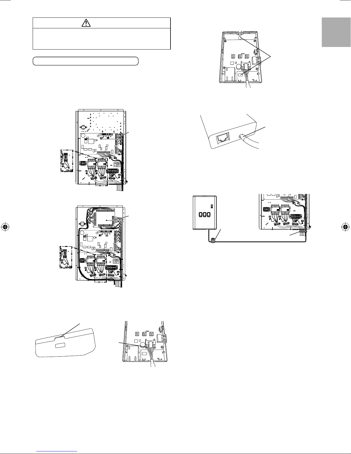
3. On the wall near the Indoor Unit, attach the adaptor by
screwing screws through the holes in the back cover.
ENGLISH
Network Adaptor 8 Installation (Optional)
1. Open the Control Board Cover 6, then connect the cable
included with this adaptor to the CN-CNT connector on the
printed circuit board.
Pull the cable out of the Indoor Unit so that there is no pinching.
•
If an optional PCB has been install in the Indoor Unit, connect
•
the CN-CNT connector to Optional PCB 7.
Connection examples: H series
CN-CNT cable
For S*C09*3E8
For S*C12/16*9E8
Without Optional PCB
CN-CNT cable
Screws
4. Pull the CN-CNT cable through the hole in the bottom of the
adaptor and re-attach the front cover to the back cover.
CN-CNT cable
(Take care not to
pinch the cable)
5. Use the included cord clamp to fi x the CN-CNT cable to the
wall.
Pull the cable around as shown in the diagram so that external
forces cannot act on the connector in the adaptor.
Furthermore, on the Indoor Unit end, use the included cable tie
to fi x the cables together.
For S*C09*3E8
For S*C12/16*9E8
With Optional PCB
2. Insert a fl at head screwdriver into the slot on the top of the
adaptor and remove the cover. Connect the other end of the
CN-CNT cable connector to the connector inside the adaptor.
Slot
Connector
Cord clamp
Cable tie
19
3
System installation
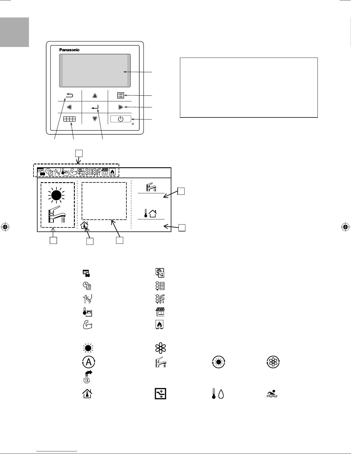
3-1. Remote Controller Outline
ENGLISH
1
Name Function
A
B
C
D
GFE
A: Main screen Display information
B: Menu Open/Close main menu
C: Triangle (Move) Select or change item
D: Operate Start/Stop operation
E: Back Back to previous item
F: Quick Menu Open/Close Quick menu
G: OK Confi rm
10:34am, Mon
40˚c
24
c
˚
2
Name Function
1: Function icon Display set function/status
2: Mode Display set mode/current status of mode
3
4
Holiday mode Demand control
Weekly timer Room heater
Quiet mode Tank heater
Remote controller room
thermostat
Powerful mode Boiler
Heating Cooling
18˚c
5
6
Solar
Auto Hot water supply Auto heating Auto cooling
Heat pump operating
3: Temp setting
4: Display Heat temp Display current heating temperature (it is set temperature when enclosed by line)
5: Display tank temp Display current tank temperature (it is set temperature when enclosed by line)
6: Outdoor temp Display outdoor temp
20
Set room temp
Compensation
curve
Set direct water
temp
Set pool temp

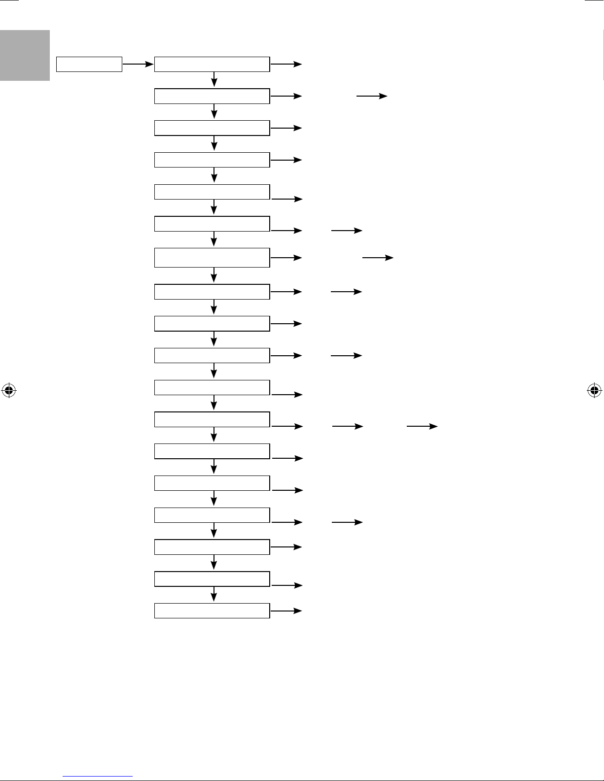
First time of power ON (Start of installation)
ENGLISH
Initialization
Initializing.
«
Start
«
Language
ENGLISH
FRANCAIS
DEUTSCH
ITALIANO
Select Confi rm
«
12:00, Mon
When power is ON, fi rstly initialization
screen appears (10 sec)
17:26, Wed
When initialization screen ends, it turns
to normal screen.
12:00, Wed
When any button is pressed, language
setting screen appears.
(CAUTION) If initial setting is not
performed, it does not go into menu.
Set language & confi rm
Clock format
24h
am/pm
Select Confi rm
Set time display & confi rm
«
Date & time
Year/Month/Day Hour : Min
2015
/ 01 / 01
Select Confi rm
Set YY/MM/DD/Time & confi rm
«
Start
Press menu, select Installer setup
«
12:00, Mon
12:00, Mon
12 : 00
17:26, Wed
When language is set, setting screen of
time display appears (24h/am/pm)
YY/MM/DD/Time setup screen appears
Back to initial screen
Main Menu
System check
Personal setup
Service contact
Installer setup
Select Confi rm
Confi rm to go into Installer setup
«
17:26, Wed
21
3-2. Installer Setup
1
System setup Optional PCB connectivity Yes/No
ENGLISH
2
Zone & Sensor
3
Heater capacity Capacity select
4
Anti freezing Yes/No
5
Tank connection
6
Only when the selection for optional PCB is Yes
Buffer Tank connection
7 Only when the selection for Tank connection is Yes
Tank heater
8
Base pan heater
9
Alternative outdoor sensor Yes/No
Only when the selection for optional PCB is Yes
1 Zone/2 Zone Zone settings
Yes/No
Yes/No T setup
External/Internal Heater ON time setup
Yes/No A / B
10
Bivalent connection
11
External SW
12
Only when the selection for optional PCB is Yes
Solar connection
13
Only when the selection for optional PCB is Yes
External Error signal
Yes/No Bivalent setup
Yes/No
Yes/No Tank setup Solar setup
Yes/No
14 Only when the selection for optional PCB is Yes
Demand control
15
Only when the selection for optional PCB is Yes
SG ready
Yes/No
Yes/No Capacity setup
16 Only when the selection for optional PCB is Yes
External Compressor SW Yes/No
17
Circulation liquid
18
Only when the selection for optional PCB is Yes
Water/glycol
Heat-Cool SW Yes/No
22
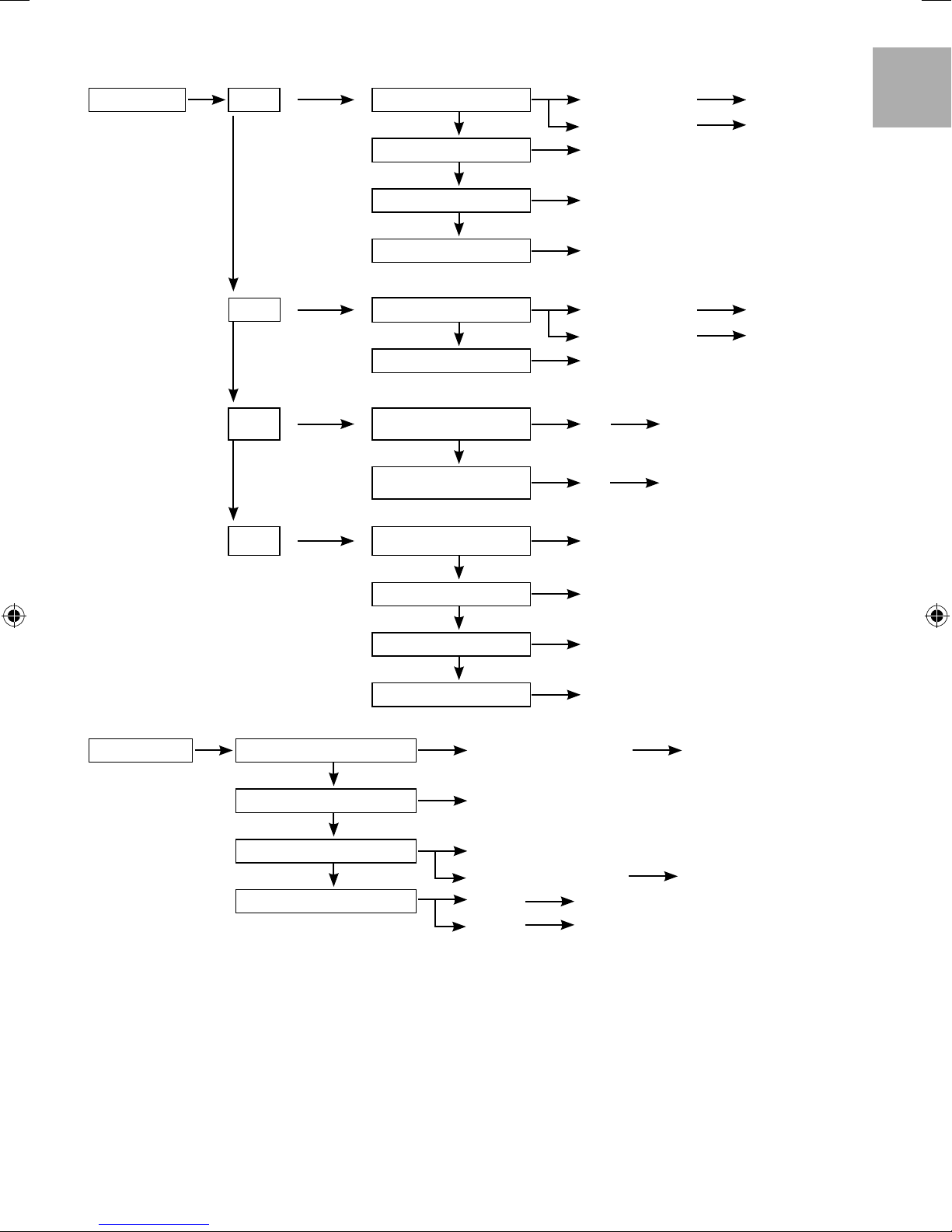
19
Operation setup Heat Water temp. for heating ON Compensation curve
20
Outdoor temp. for heating OFF
21
Direct Direct temp. setup
Heating OFF Temp. setup
T for heating ON T for heating setup
22
Outdoor temp. for heater ON
O/D temp for heater ON setup
Compensation
curve setup
ENGLISH
Cooling model only
23 (Display only if Cool exist, or else skip)
Cool Water temp. for cooling ON Compensation curve
24
Cooling model only
25
Auto
26
Only when the
selection for Tank
is Yes
27
Tank Floor operation time (max.) Max. operation time for Heat & Cool mode setup
28
29
30
31
Service setup Pump maximum speed
Compensation
curve setup
T for Cooling ON
Outdoor temp. for
(Heat to Cool)
Outdoor temp. for
(Cool to Heat)
Direct Direct temp. setup
T for cooling setup
Heat Cool change temp. setup
Cool Heat change temp. setup
Tank heat up time (max.) Max. operation time for Tank mode setup
Tank re-heat temp. Tank re-heat temp. setup
Sterilization Sterilization day and temp. and time setup
Pump maximum speed setup Air purge
32
Pump down Pump down ON / OFF
33
Dry concrete ON (Dry concrete)
34
Service contact
Edit (Dry concrete schedule) Day and temp. setup
Contact 1 Name and Tel No. setup
Contact 2
Name and Tel No. setup
23
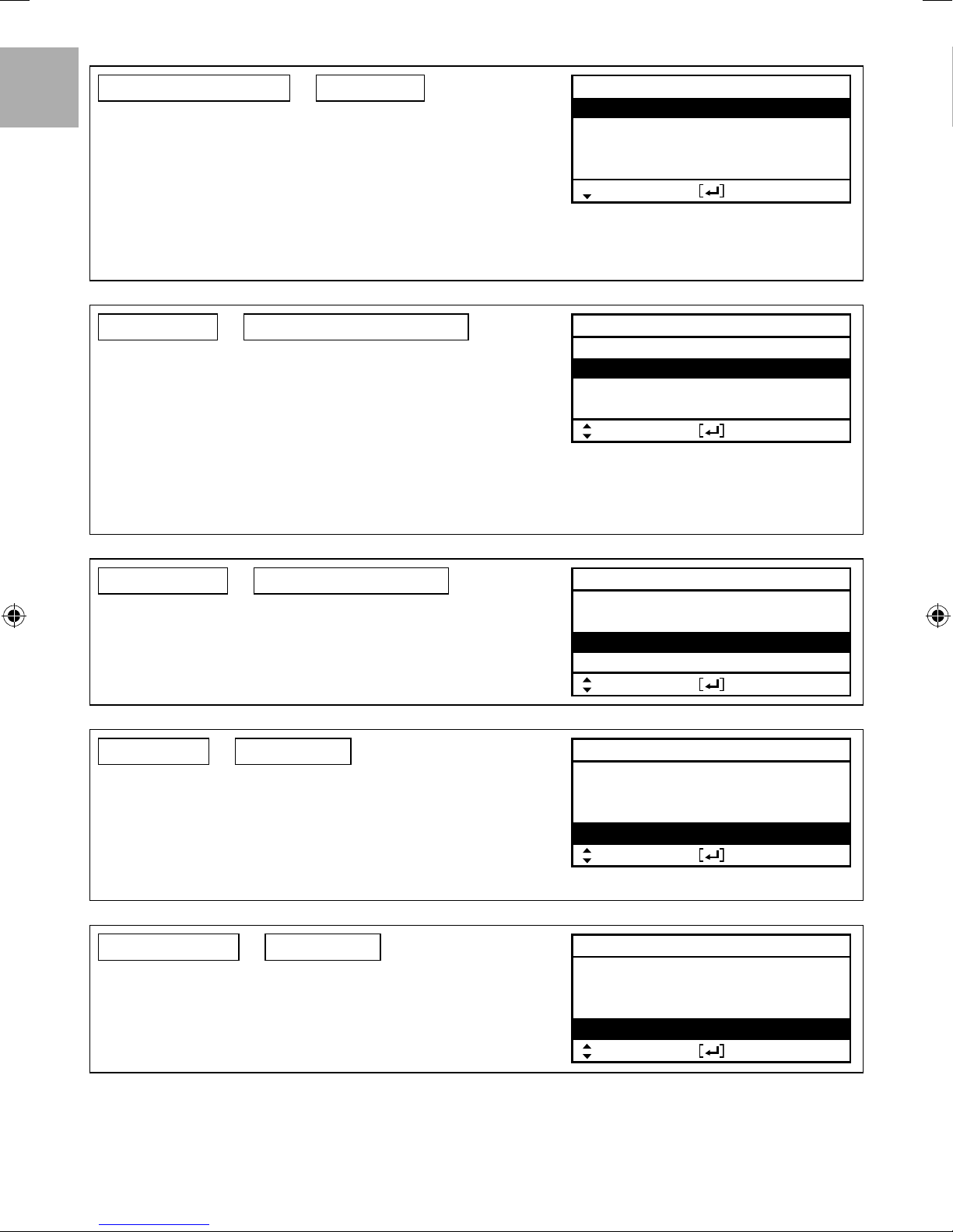
3-3. System Setup
1. Optional PCB connectivity
ENGLISH
If function below is necessary, please purchase and install optional PCB.
Please select Yes after installing optional PCB.
2-zone control
•
Pool
•
Buffer tank
•
Solar
•
External error signal output
•
Demand control
•
SG ready
•
Stop heat source unit by external SW
•
2. Zone & Sensor
If no Optional PCB connectivity
Select sensor of room temperature control from the following 3 items
1 Water temperature (circulation water temperature)
2 Room thermostat (Internal or External)
3 Room thermistor
When there is Optional PCB connectivity
1 Select either 1 zone control or 2 zone control.
If it is 1 zone, select either room or pool, select sensor
If it is 2 zone, after select sensor of zone 1, select either room or pool for zone
2, select sensor
(CAUTION) In 2 zone system, pool function can be set at zone 2 only.
Initial setting: Room and Water temp.
Initial setting: No
System setup
Optional PCB connectivity
Zone & Sensor
Heater capacity
Anti freezing
Select Confi rm
System setup
Optional PCB connectivity
Zone & Sensor
Heater capacity
Anti freezing
Select Confi rm
17:26, Wed
17:26, Wed
3. Heater capacity
If there is built-in Heater, set the selectable heater capacity.
(CAUTION) There are models which cannot select heater.
4. Anti freezing
Operate anti-freezing of water circulation circuit.
If select Yes, when the water temperature is reaching its freezing temperature, the
circulation pump will start up. If the water temperature does not reach the pump
stop temperature, back-up heater will be activated.
(CAUTION) If set No, when the water temperature is reaching its freezing
temperature or below 0°C, the water circulation circuit may freeze and
cause malfunction.
5. Tank connection
Select whether it is connected to hot water tank or not.
If set Yes, it becomes setting that uses hot water function.
Hot water temperature of tank can be set from main screen.
Initial setting: Depend on model
Initial setting: Yes
Initial setting: No
System setup
Optional PCB connectivity
Zone & Sensor
Heater capacity
Anti freezing
Select Confi rm
System setup
Optional PCB connectivity
Zone & Sensor
Heater capacity
Anti freezing
Select Confi rm
System setup
Zone & Sensor
Heater capacity
Anti freezing
Tank connection
Select Confi rm
17:26, Wed
17:26, Wed
17:26, Wed
24
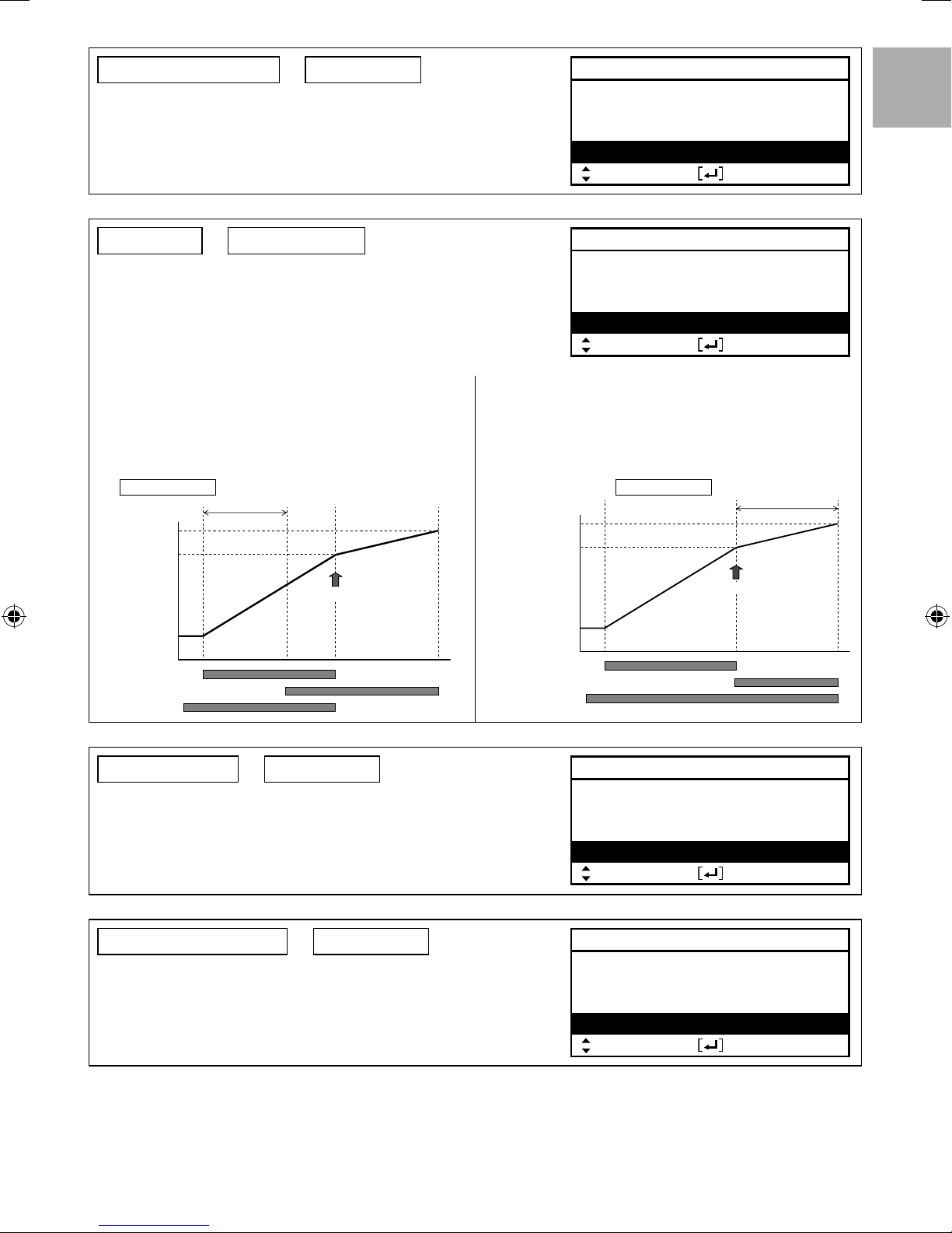
6. Buffer Tank connection
Initial setting: No
Select whether it is connected to buffer tank for heating or not.
If buffer tank is used, please set Yes.
Connect buffer tank thermistor and set, T (T use to increase primary side temp
against secondary side target temp).
(CAUTION) Does not display if there is no Optional PCB.
If the buffer tank capacity is not so large, please set larger value for T.
System setup
Heater capacity
Anti freezing
Tank connection
Buffer tank connection
Select Confi rm
ENGLISH
17:26, Wed
7. Tank heater
Initial setting: Internal
Select to use either built-in heater or external heater as heater for hot water tank.
If heater is installed on tank, please select External.
(CAUTION) Does not display if there is no tank for hot water supply.
Please set “Tank heater” to “ON” in the “Function setup” from remote controller
when using heater to boil the tank.
External A setting which is using booster heater installed on
Internal A setting which is using backup heater of indoor unit to
DHW tank to boil the tank.
The permissible heater capacity is 3kW and below.
The operation to boil the tank with heater is as below.
The operation to boil the tank with heater is as below.
In addition, be sure to set suitable “Tank heater: ON
time”
For 65°C setting
Tank temp.
ON time
65
53
HP thermo OFF
HP
Booster heater
Pump
Tank temp.
HP
Backup heater
Pump
System setup
Anti freezing
Tank connection
Buffer tank connection
Tank heater
Select Confi rm
boil the tank.
65
53
17:26, Wed
For 65°C setting
A
HP thermo OFF
8. Base pan heater
Initial setting: No
Select whether Base pan heater is installed or not.
If set Yes, select to use either heater A or B.
A: Turn on Heater when heating with defrost operation only
B: Turn on Heater at heating
9. Alternative outdoor sensor
Set Yes if outdoor sensor is installed.
Controlled by optional outdoor sensor without reading the outdoor sensor of heat
pump unit.
Initial setting: No
System setup
Tank connection
Buffer tank connection
Tank heater
Base pan heater
Select Confi rm
System setup
Buffer tank connection
Tank heater
Base pan heater
Alternative outdoor sensor
Select Confi rm
17:26, Wed
17:26, Wed
25
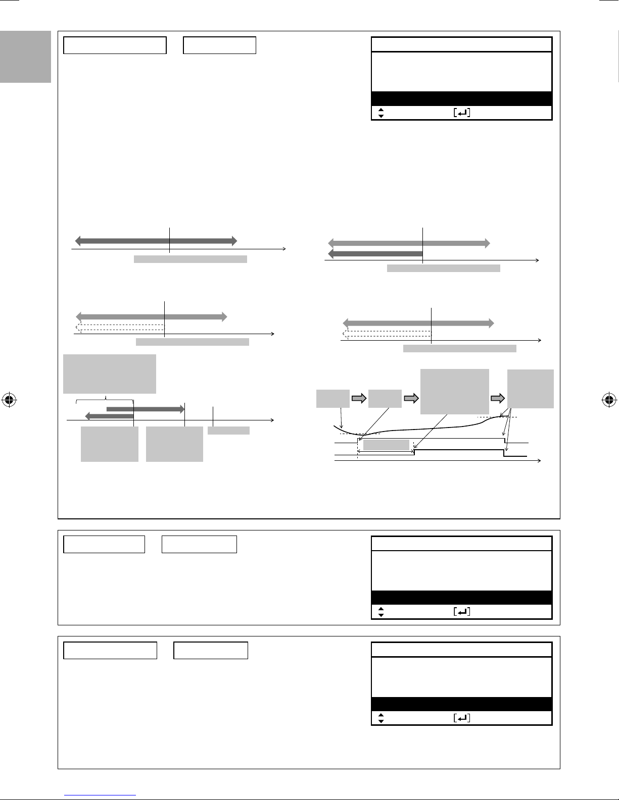
10. Bivalent connection
Initial setting: No
System setup
Tank heater
Set if heat pump linked with boiler operation.
ENGLISH
Connect the start signal of the boiler in boiler contact terminal (main PCB).
Set Bivalent connection to YES.
After that, please begin setting according to remote controller instruction.
Boiler icon will be displayed on remote controller top screen.
Base pan heater
Alternative outdoor sensor
Bivalent connection
Select Confi rm
There are 3 different modes in the boiler operation. Movement of each modes are shown below.
1 Alternative (switch to boiler operation when drops below setting temperature)
2 Parallel (allow boiler operation when drops below setting temperature)
3 Advanced Parallel (able to slightly delay boiler operation time of parallel operation)
When the boiler operation is “ON”, “boiler contact” is “ON”, “_”(underscore) will be displayed below the boiler icon.
Please set target temperature of boiler to be the same as heat pump temperature.
When boiler temperature is higher than heat pump temperature, zone temperature cannot be achieved if mixing valve is not installed.
This product only allows one signal to control the boiler operation. Operation setting of boiler shall be responsible by installer.
Alternative mode
operate boiler only
operate heat pump only
Outdoor temp.
-10°C (setting from remote controller)
Parallel mode
operate boiler and heat
pump simultaneously
operate heat pump only
-10°C (setting from remote controller)
Advanced Parallel mode
For heating
operate boiler and heat
pump simultaneously
-10°C (setting from remote controller)
Although heat pump operates
but water temperature does
not reach this temperature for
more than 30 mins (setting
from remote controller)
Boiler temp. ON
= Setting -8°C
(setting from
remote controller)
operate heat pump only
AND
Boiler temp. OFF
= Setting -2°C
(setting from
remote controller)
Outdoor temp.
Circulation water temp.
Setting temp
Tank temp.
Tank
temp.
Heat
pump
Boiler
Lowering
For DHW tank
operate boiler and heat
pump simultaneously
Heat pump
thermo ON
Boiling initial
temp.
30 min (setting from
remote control)
operate heat pump only
-10°C (setting from remote controller)
AND
If actual tank temp. does
not achieve the setting
temp. within 30min
(setting from remote
controller), the boiler
turn ON
In Advanced Parallel mode, setting for both heating and tank can
be made simultaneously. During operation of “Heating/Tank” mode,
when each time the mode is switched, the boiler output will be
reset to OFF. Please have good understanding on the boiler control
characteristic in order to select the optimal setting for the system.
17:26, Wed
Outdoor temp.
Outdoor temp.
When tank
temp. is
achieved, both
operations
stop
Tank setting
temp.
time
11. External SW
Initial setting: No
Able to turn ON/OFF the operation by external switch.
12. Solar connection
Initial setting: No
Set when solar water heater is installed.
Setting include items below.
1 Set either buffer tank or DHW tank for connection with solar water heater.
2 Set temperature difference between solar panel thermistor and buffer tank or
DHW tank thermistor to operate the solar pump.
3 Set temperature difference between solar panel thermistor and buffer tank or
DHW tank thermistor to stop the solar pump.
4 Anti-freezing operation start temperature (please change setting based on usage of glycol.)
5 Solar pump stop operation when it exceeds high limit temperature (when tank temperature exceed designated temperature (70~90°C))
26
System setup
Base pan heater
Alternative outdoor sensor
Bivalent connection
External SW
Select Confi rm
System setup
Alternative outdoor sensor
Bivalent connection
External SW
Solar connection
Select Confi rm
17:26, Wed
17:26, Wed
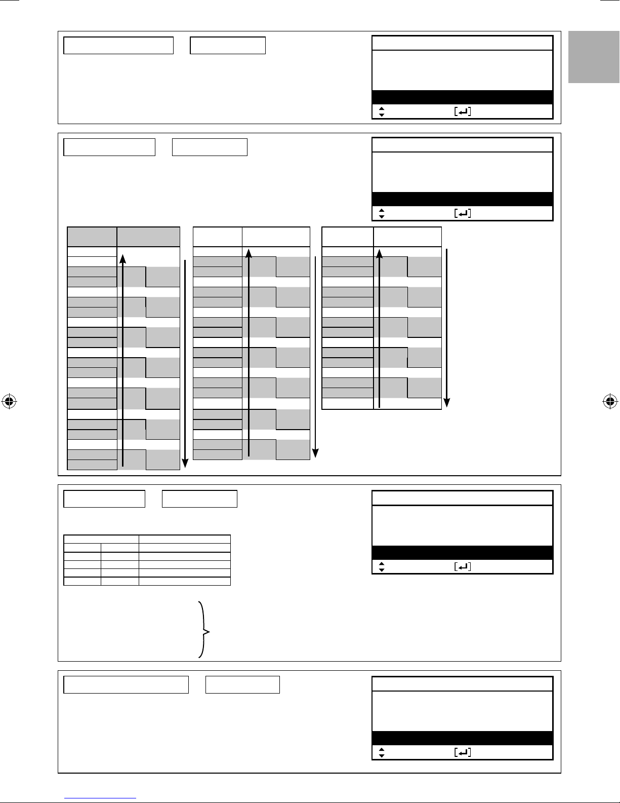
13. External Error Signal
Initial setting: No
Set when external error display unit is installed.
Turn on Dry Contact SW when error happened.
(CAUTION) Does not display when there is no Optional PCB.
When error occurs, error signal will be ON.
After turn off “close” from the display, error signal will still remain ON.
System setup
Bivalent connection
External SW
Solar connection
External error signal
Select Confi rm
ENGLISH
17:26, Wed
14. Demand control
Initial setting: No
Set when there is demand control.
Adjust terminal voltage within 1 ~ 10 V to change the operating current limit.
(CAUTION) Does not display when there is no Optional PCB.
Analog input
[v]
0.0
0.1 ~ 0.6 4.2
0.7
0.8 4.4 ~ 4.6 45 7.9 ~ 8.1 80
0.9 ~ 1.1 10 4.7
1.2
1.3 4.9 ~ 5.1 50 8.4 ~ 8.6 85
1.4 ~ 1.6 15 5.2
1.7
1.8 5.4 ~ 5.6 55 8.9 ~ 9.1 90
1.9 ~ 2.1 20 5.7
2.2
2.3 5.9 ~ 6.1 60 9.4 ~ 9.6 95
2.4 ~ 2.6 25 6.2
2.7
2.8 6.4 ~ 6.6 65 9.9 ~ 100
2.9 ~ 3.1 30 6.7
3.2
3.3 6.9 ~ 7.1 70
3.4 ~ 3.6 35 7.2
3.7
3.8
Rate
[%]
not activate
not
10
activate
15 10
20 15
25 20
30 25
35 30
40 35
Analog input
[v]
Rate
[%]
Analog input
[v]
3.9 ~ 4.1 40 7.4 ~ 7.6 75
4.3 7.8
4.8 8.3
5.3 8.8
5.8 9.3
6.3 9.8
6.8
7.3
45 40
50 45
55 50
60 55
65 60
70 65
75 70
7.7
8.2
8.7
9.2
9.7
*A minimum operating current is applied on each model for
protection purpose.
*0.2 voltage hysteresis is provided.
* The value of voltage after 2nd decimal point are cut off.
System setup
External SW
Solar connection
External error signal
Demand control
Select Confi rm
Rate
[%]
80 75
85 80
90 85
95 90
100 95
17:26, Wed
15. SG ready
Initial setting: No
Switch operation of heat pump by open-short of 2 terminals.
Setting belows are possible
SG signal Working pattern
Vcc-bit1 Vcc-bit2
Open Open Normal
Short Open Heat pump and Heater OFF
Open Short Capacity 1
Short Short Capacity 2
Capacity setting 1
- Heating capacity ___%
- DHW capacity ___%
Capacity setting 2
- Heating capacity ___%
- DHW capacity ___%
16. External Compressor SW
Set when external compressor SW is connected.
SW is connected to external devices to control power consumption, ON signal will
stop compressor’s operation. (Heating operation etc. are not cancelled).
(CAUTION) Does not display if there is no Optional PCB.
If follow Swiss standard power connection, need to turn on DIP SW of main unit
PCB. ON/OFF signal used to ON/OFF tank heater (for sterilization purpose)
Set by SG ready setting of remote controller
Initial setting: No
System setup
Solar connection
External error signal
Demand control
SG ready
Select Confi rm
System setup
External error signal
Demand control
SG ready
External compressor SW
Select Confi rm
17:26, Wed
17:26, Wed
27
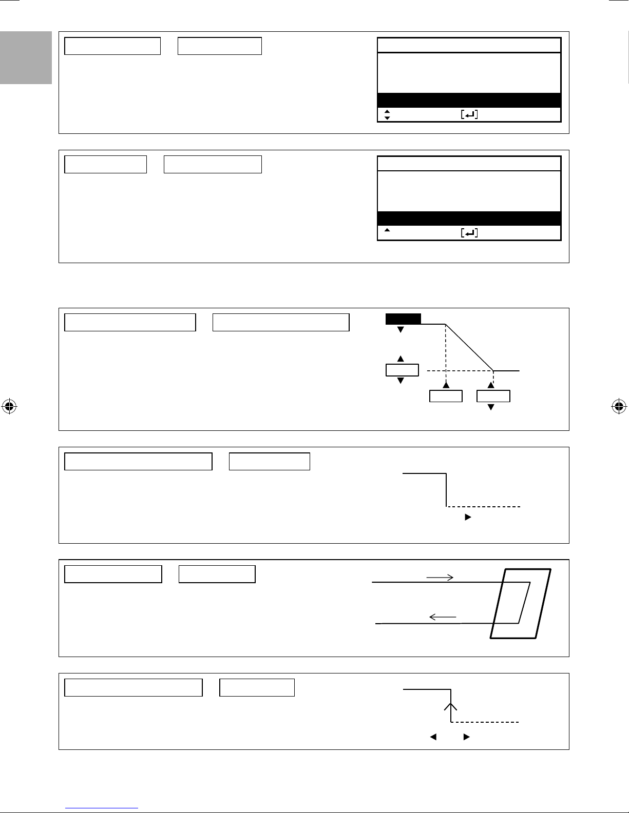
17. Circulation Liquid
Set circulation of heating water.
ENGLISH
There are 2 types of settings, water and anti-freeze function.
(CAUTION) Please set glycol when using anti-freeze function.
It may cause error if setting is wrong.
Initial setting: Water
System setup
Demand control
SG ready
External compressor SW
Circulation liquid
Select Confi rm
17:26, Wed
18. Heat-Cool SW
Able to switch (fi x) heating & cooling by external switch.
(Open)
: Fix at Heating (Heating +DHW)
(Short) : Fix at Cooling (Cooling +DHW)
(CAUTION) This setting is disabled for model without Cooling.
(CAUTION) Does not display if there is no Optional PCB.
Timer function cannot be used. Cannot use Auto mode.
Initial setting: Disable
3-4. Operation Setup
Heat
19. Water temp. for heating ON
Set target water temperature to operate heating operation.
Compensation curve: Target water temperature change in conjunction with
outdoor ambient temperature change.
Direct: Set direct circulation water temperature.
In 2 zone system, zone 1 and zone 2 water temperature can be set separately.
Initial setting: compensation curve
System setup
SG ready
External compressor SW
Circulation liquid
Heat-Cool SW
Select Confi rm
55°C
Hot water temperature
35°C
Decide temperature
of 4 points as shown
in diagram
-5°C
15°C
compensation curve
17:26, Wed
Outdoor
temperature
20. Outdoor temp. for heating OFF
Set outdoor temp to stop heating.
Setting range is 5°C ~ 35°C
21. T for heating ON
Set temp difference between out temp & return temp of circulating water of
Heating operation.
When temp gap is enlarged, it is energy saving but less comfort. When the
gap gets smaller, energy saving effect gets worse but it is more comfortable.
Setting range is 1°C ~ 15°C
22. Outdoor temp. for heater ON
Set outdoor temp when back-up heater starts to operate.
Setting range is -15°C ~ 20°C
User shall set whether to use or not to use heater.
Initial setting: 5°C
Initial setting: 24°C
Initial setting: 0°C
ON
24°C
Out
Return
Out — Return = 1°C ~ 15°C
ON
0°C
OFF
OFF
28
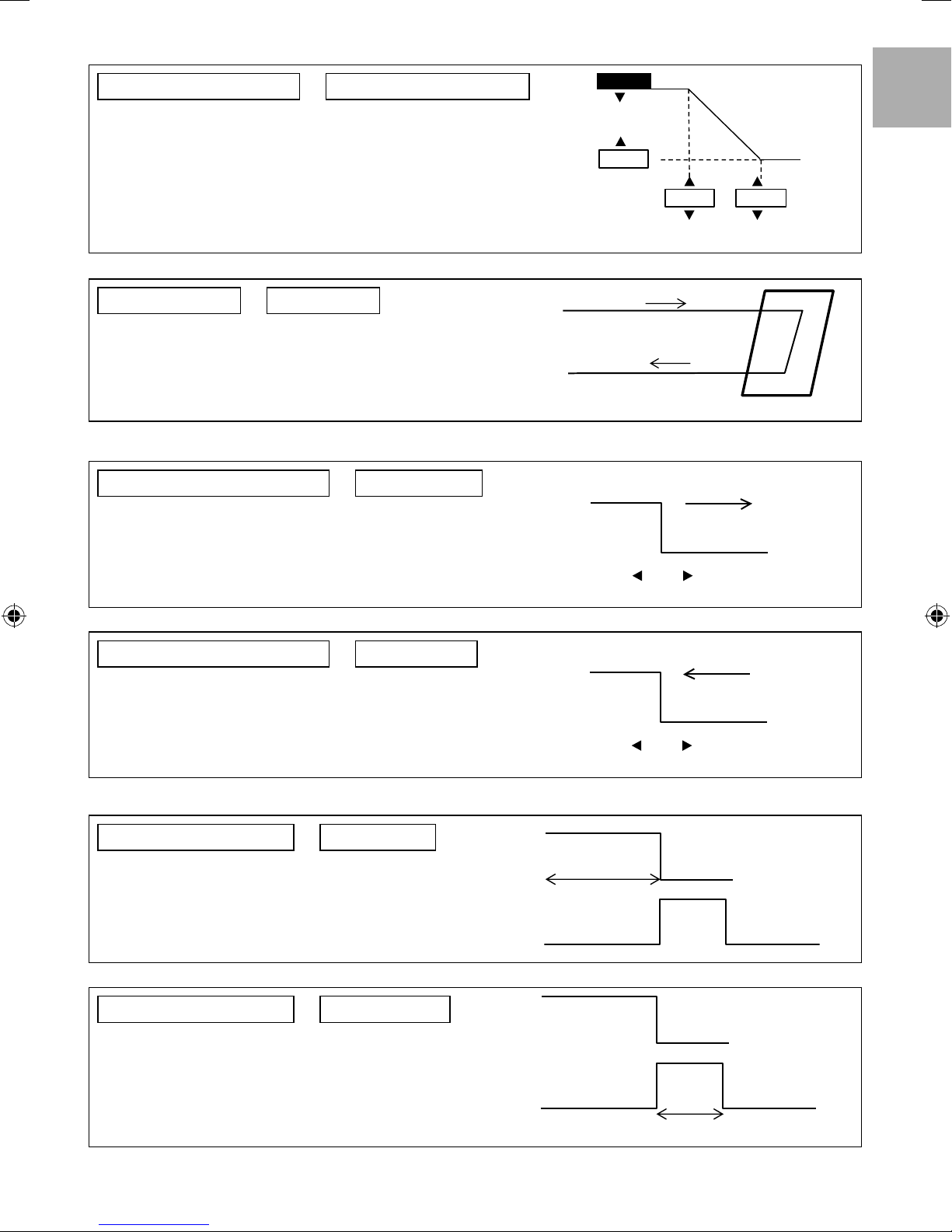
Cool
23. Water temp. for cooling ON
Set target water temperature to operate cooling operation.
Compensation curve: Target water temperature change in conjunction with
outdoor ambient temperature change.
Direct: Set direct circulation water temperature.
In 2 zone system, zone 1 and zone 2 water temperature can be set separately.
Initial setting: compensation curve
20°C
5°C
20°C 30°C
compensation curve
ENGLISH
24. T for cooling ON
Set temp difference between out temp & return temp of circulating water of
Cooling operation.
When temp gap is enlarged, it is energy saving but less comfort. When the
gap gets smaller, energy saving effect gets worse but it is more comfortable.
Setting range is 1°C ~ 15°C
Auto
25. Outdoor temp. for (Heat to Cool)
Set outdoor temp that switches from heating to cooling by Auto setting.
Setting range is 5°C ~ 25°C
Timing of judgement is every 1 hour
26. Outdoor temp. for (Cool to Heat)
Set outdoor temp that switches from Cooling to Heating by Auto setting.
Setting range is 5°C ~ 25°C
Timing of judgement is every 1 hour
Initial setting: 5°C
Initial setting: 15°C
Initial setting: 10°C
Out
Return
Return — Out = 1°C ~ 15°C
Heat
Heat
Outdoor temp. rising
Cool
15°C
Outdoor temp. dropping
Cool
10°C
Tank
27. Floor operation time (max)
Set max operating hours of heating.
When max operation time is shortened, it can boil the tank more frequently.
It is a function for Heating + Tank operation.
28. Tank heat up time (max)
Set max boiling hours of tank.
When max boiling hours are shortened, it immediately returns to Heating
operation, but it may not fully boil the tank.
Initial setting: 8h
Heat
30min ~ 10h
Tank
Initial setting: 60min
Heat
Tank
5min ~ 4h
29
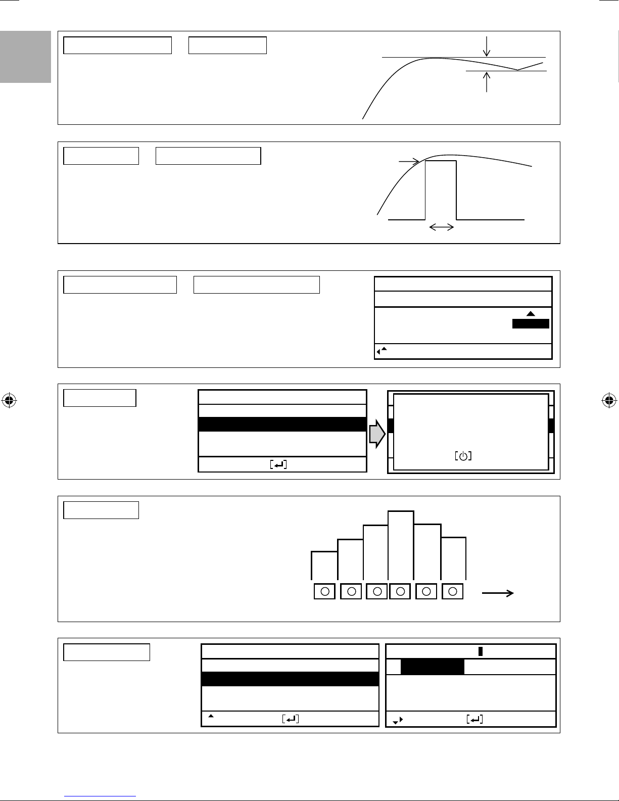
29. Tank re-heat temp.
Set temp to perform reboil of tank water.
ENGLISH
(When boiled by heat pump only, (51°C – Tank re-heat temp) shall become
max temp.)
Setting range is -12°C ~ -2°C
Initial setting: -8°C
-12°C ~ -2°C
30. Sterilization
Set timer to perform sterilization.
1 Set operating day & time. (Weekly timer format)
2 Sterilization temp (55~75°C If use back-up heater, it is 65°C)
3 Operation time (Time to run sterilization when it reached setting temp
5min ~ 60min)
User shall set whether to use or not to use sterilization mode.
Initial setting: 65°C 10min
3-5. Service Setup
31. Pump maximum speed
Normally setting is not necessary.
Please adjust when need to reduce the pump sound etc.
Besides that, it has Air Purge function.
32. Pump down
Operate pump down operation
Initial setting: Depend on model
Service setup
Pump down:
ON
17:26, Wed
②
① ③
Service setup
Flow rate Max. Duty Operation
88:8 L/min 0xCE
Select
Service setup
Pump down:
Pump down operation
in progress!
ON
17:26, Wed
Air Purge
17:26, Wed
33. Dry concrete
Operate concrete curing operation.
Select Edit, set temp for every stage (1~99 1 is for 1 day).
Setting range is 25~55°C
When it is turned ON, dry concrete starts.
When it is 2 zone, it dries both zones.
34. Service contact
Able to set name & tel no. of contact
person when there is breakdown
etc. or client has trouble. (2 items)
Service setup
Service contact:
Select Confi rm
Confi rm
Contact 1
Contact 2
45°C
40°C 40°C
35°C 35°C
30°C
123
17:26, Wed
Contact-1: Bryan Adams
A B C D E F G H I J K L M N O P Q R
S T U V W X Y Z a b c d e f g h i
j k l m n o p q r s t u v w x y z
OFF
Confi rm
56
4
ABC/ abc 0-9/ Other
Select Enter
Stage
30
 Loading...